Tamiya TRF 501X WE Project
Page 1: Assembly
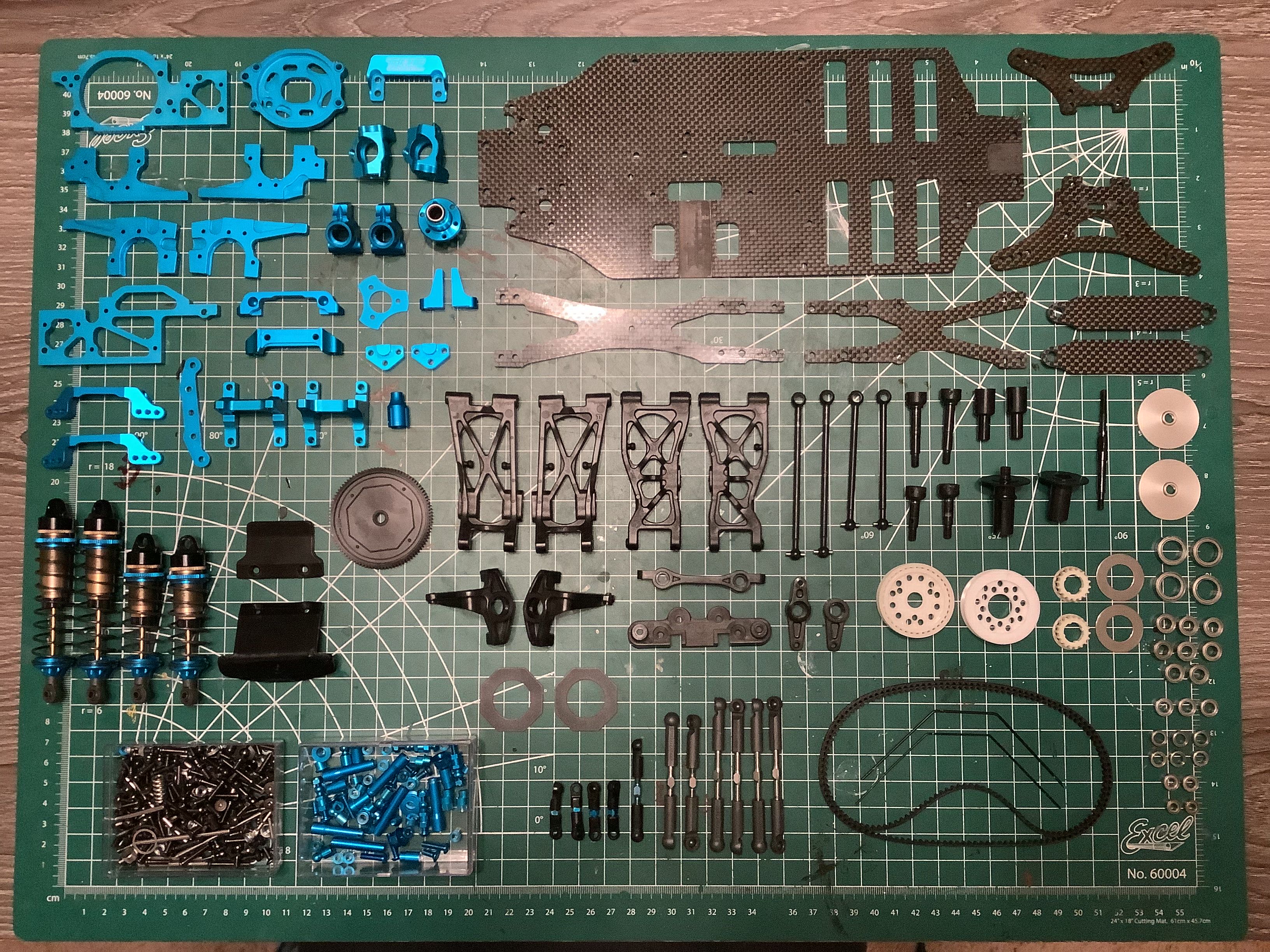
The model arrived assembled so the first thing I did was to disassemble
everything down to the last nut and bolt (shocks excepted). Given
the special nature of the model, and because I wanted to see what I was
dealing with, I decided to knoll out the parts as shown. One issue
with buying a model that has already been built versus one that is new
in the box is the possibility that the previous owner has changed
things. That certainly turned out to be the case here. Some
changes are upgrades I'll keep, and others I'll revert back to the
original design intent.
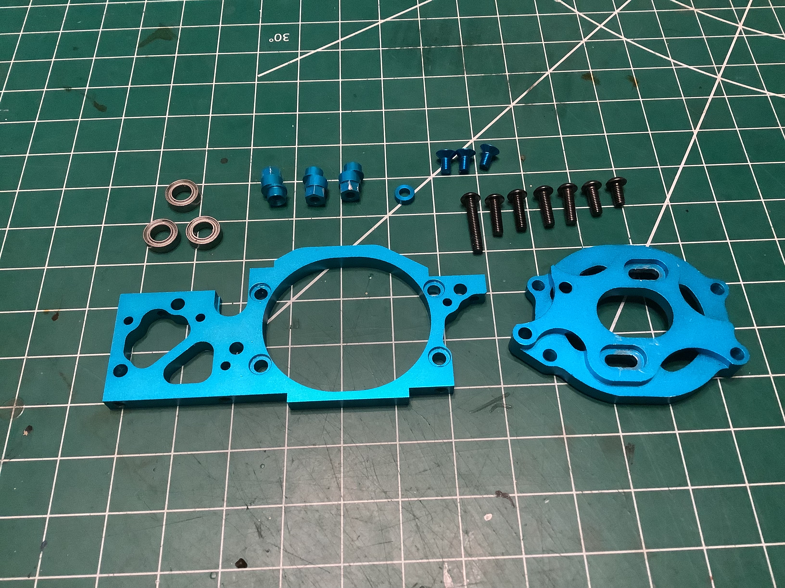
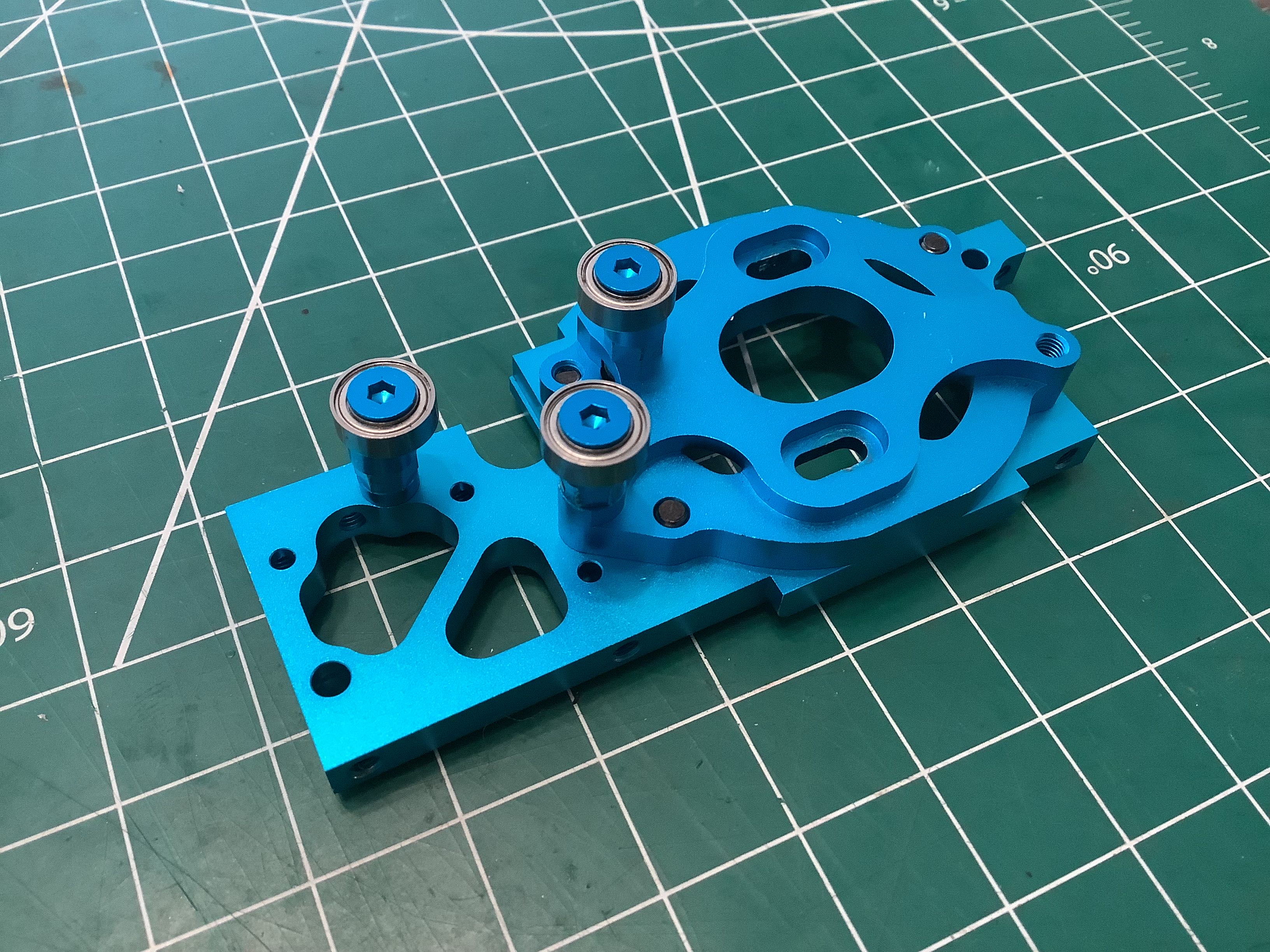
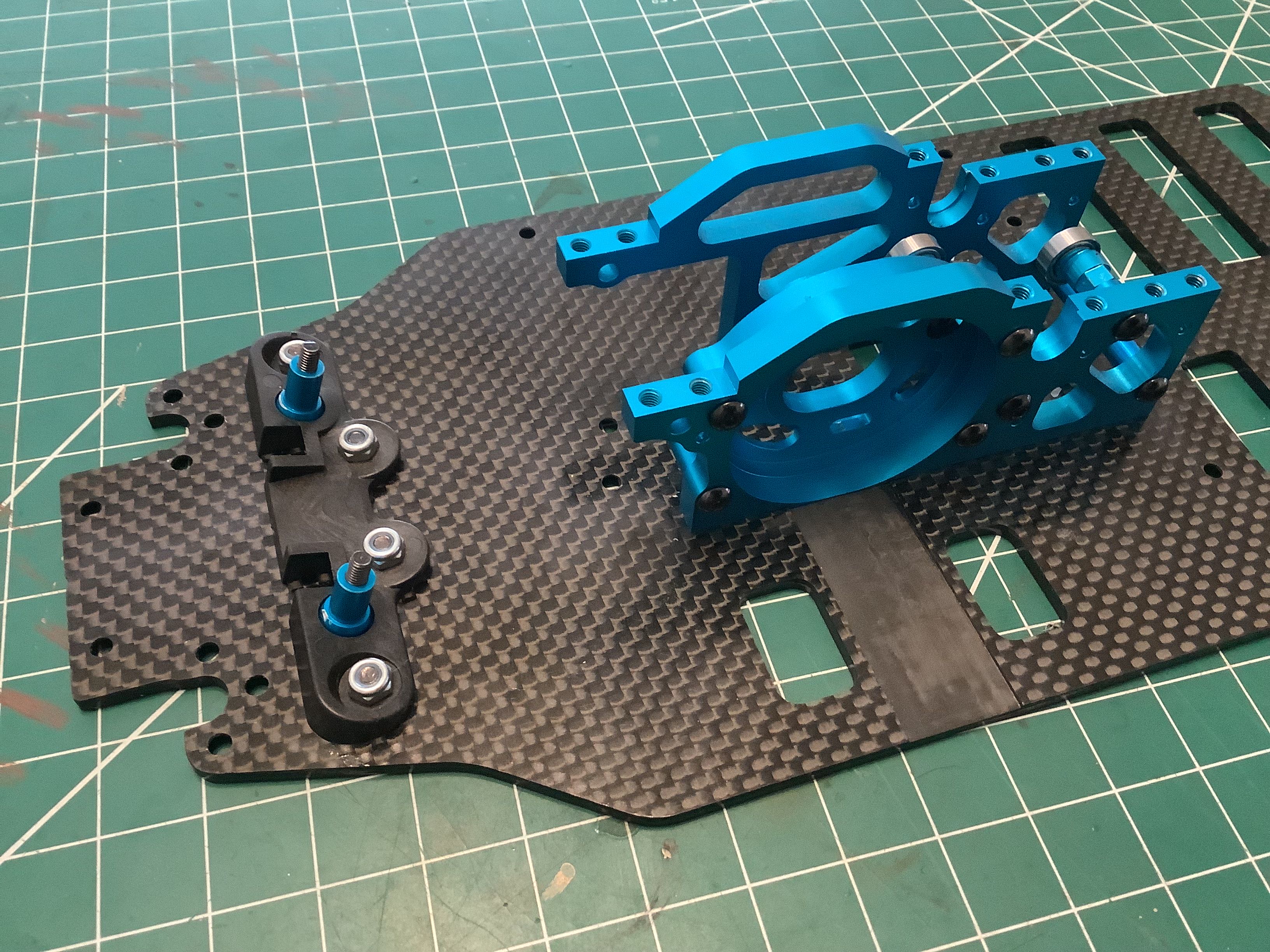
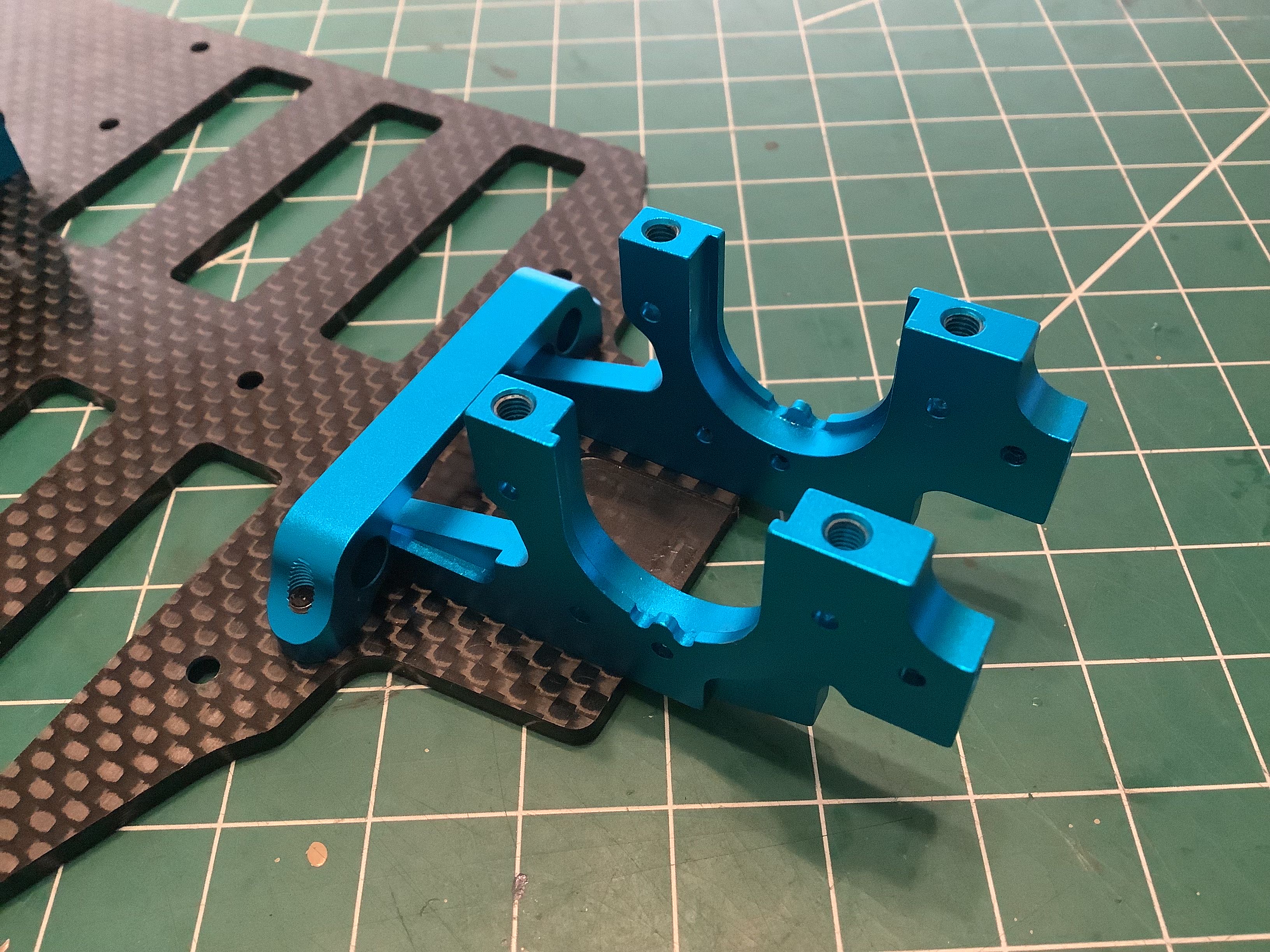
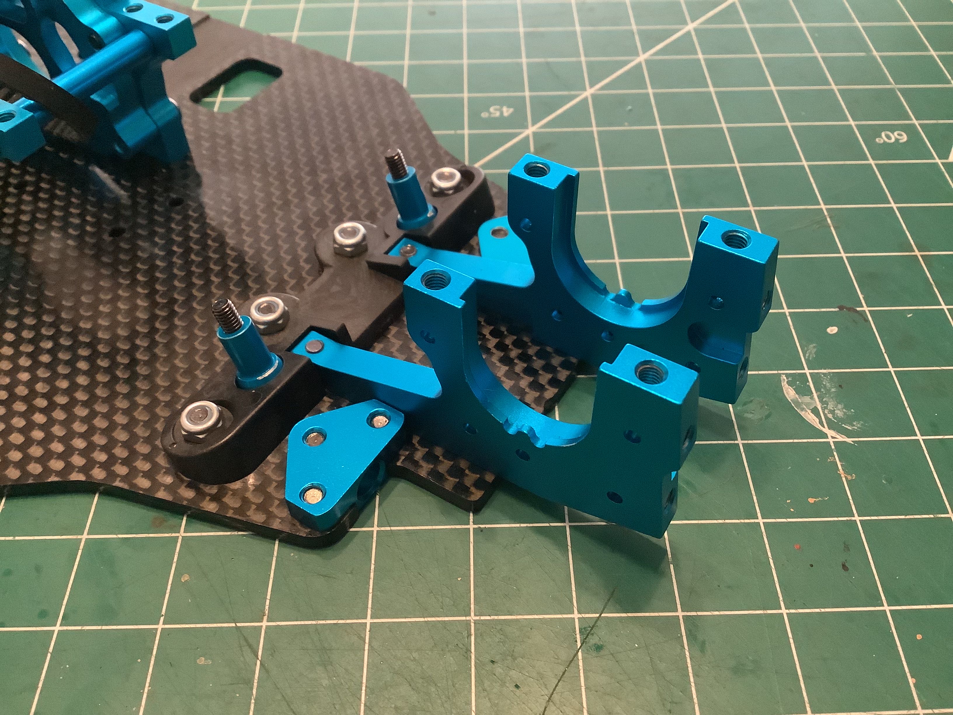
The left photo shows the parts for the first
half of the center bulkhead which also serves as a motor mount. There are 3
bearing posts which serve to guide the belts and keep them from
slapping. The original posts were straight and could not be
adjusted. The new posts (on the right) are cam shaped so you can
adjust their radial position by rotating the posts.
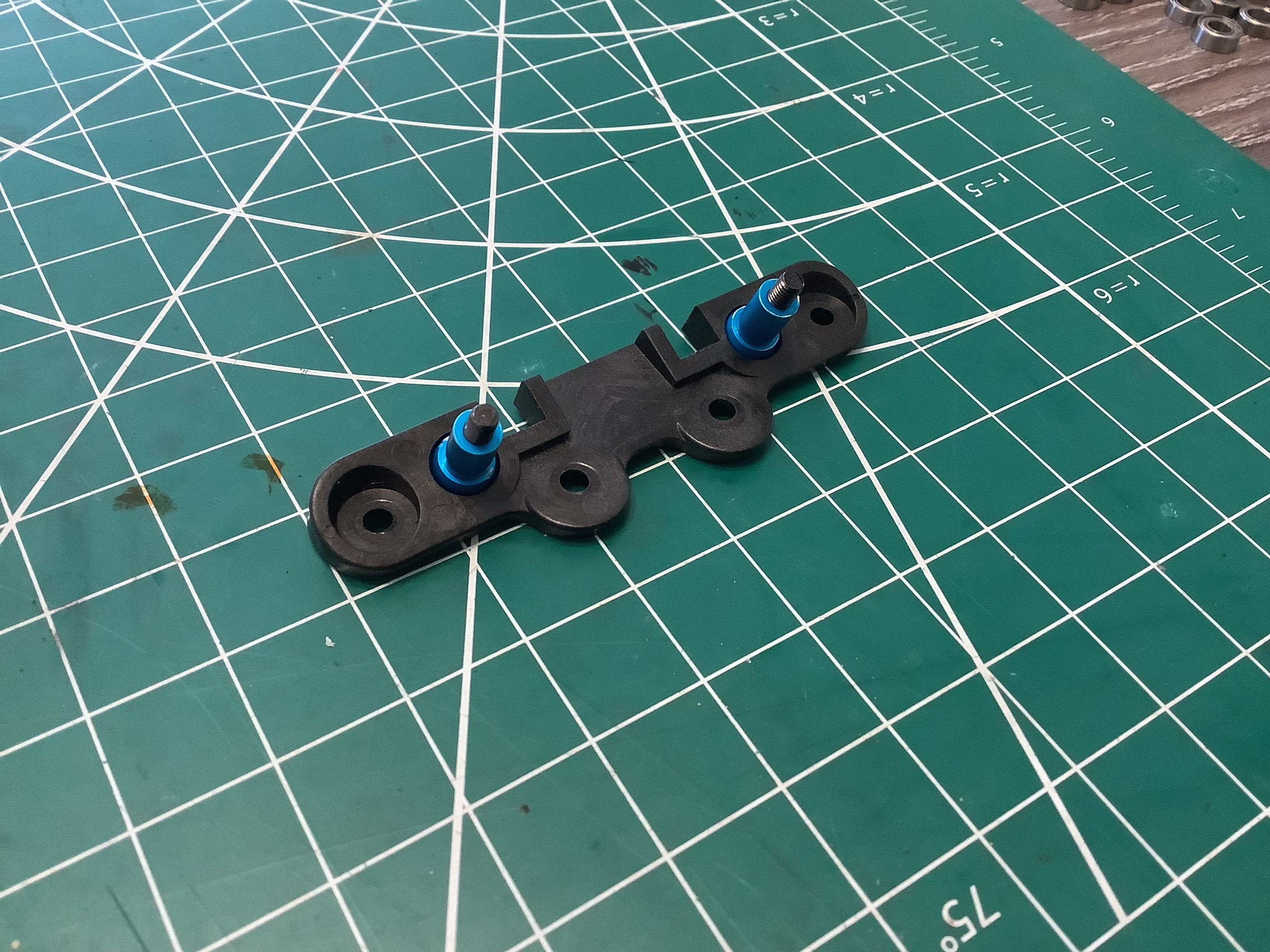
A set of blue aluminum steering posts attach to an angled plate.
There is no kick-up angle for the front axle on this flat carbon
chassis, but the steering posts are still tilted back slightly.
The right hand photo shows both sides of the center bulkhead attached to
the chassis plate. At this point there is only a single standoff
connecting the two sides. There will be a laterally mounted
motor.
Note the groove on the chassis plate which will allow the motor to sit
as low as possible.
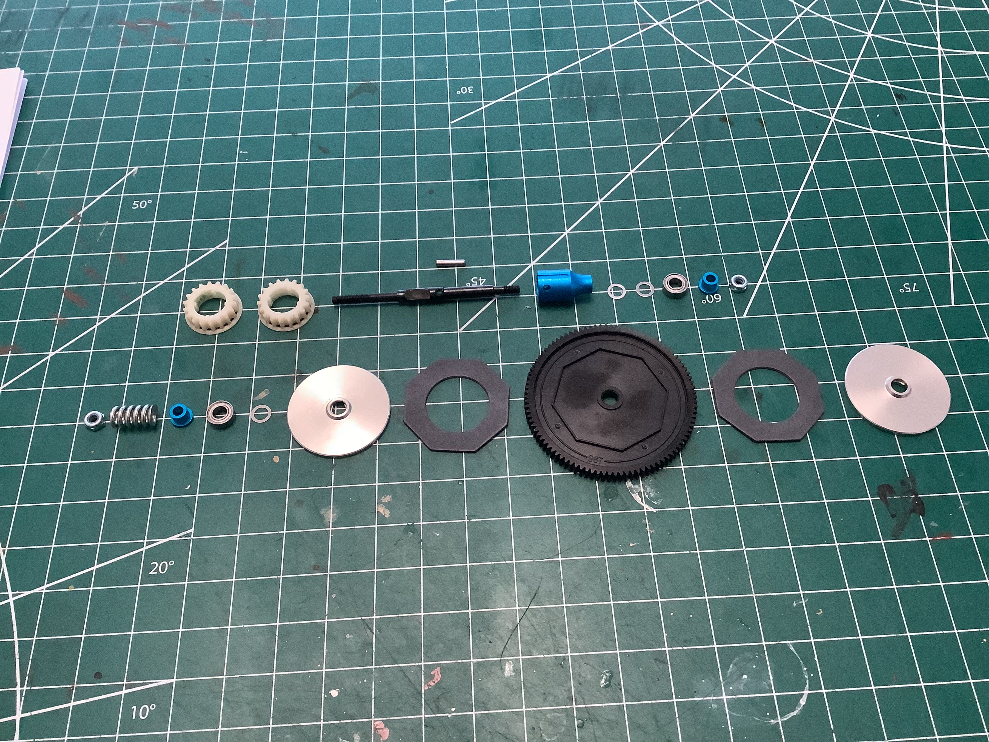
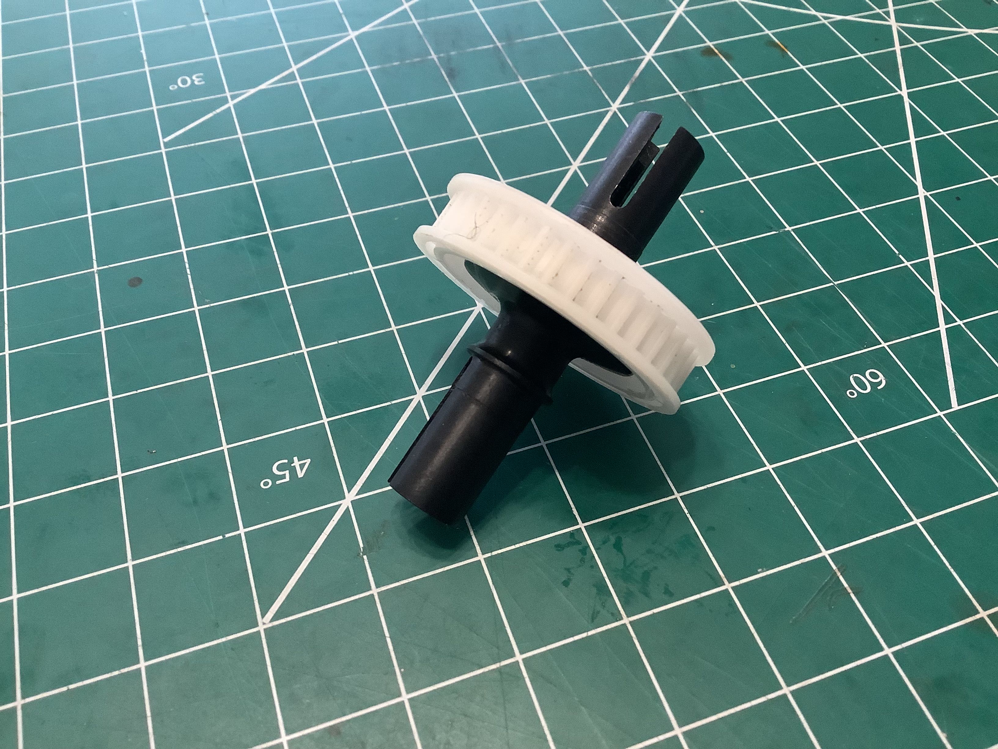
The picture on the left shows the stack of parts that will make up the
slipper clutch. The clutch is integrated with the spur gear, and
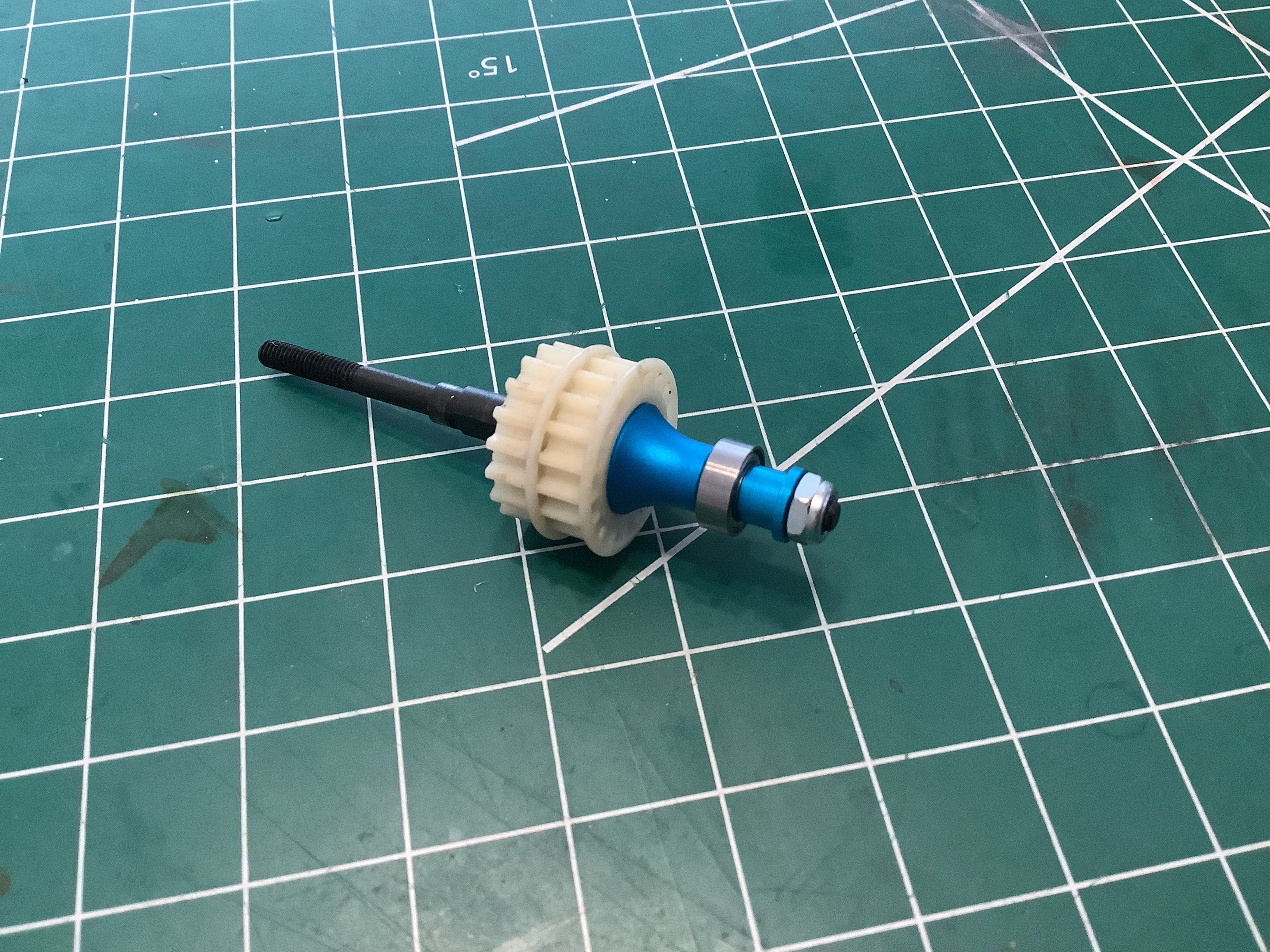
the other end of the shaft contains the drive pulleys (right). The
original TRF501X used 16 tooth pulleys, but the World Edition changes
these to 18 tooth which will serve to increase the speed of the
buggy. The slipper pads are also apparently upgraded on the World
Edition compared to the original, but I can't tell what is different
about
them. I suppose they are intended to last longer.
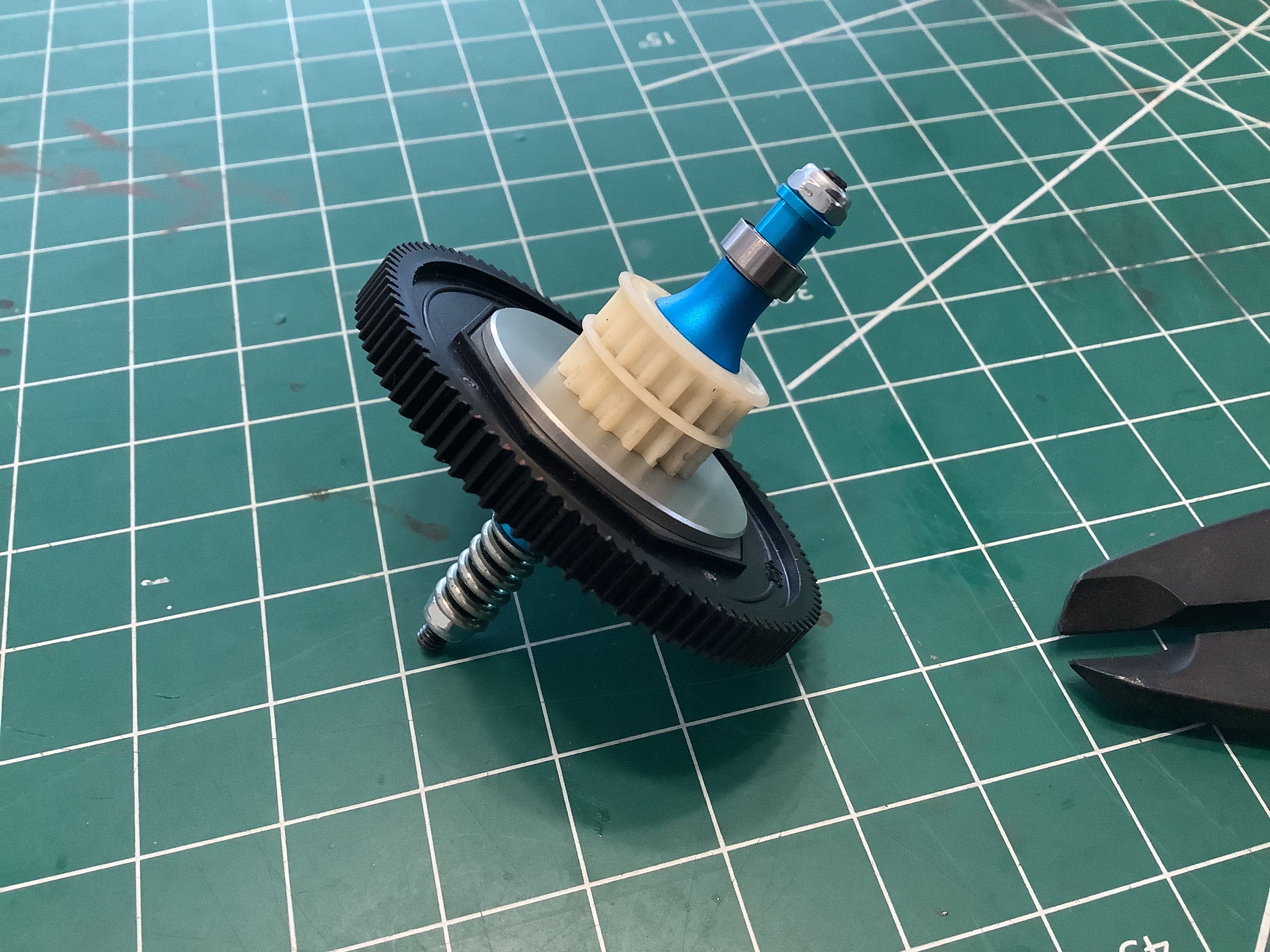
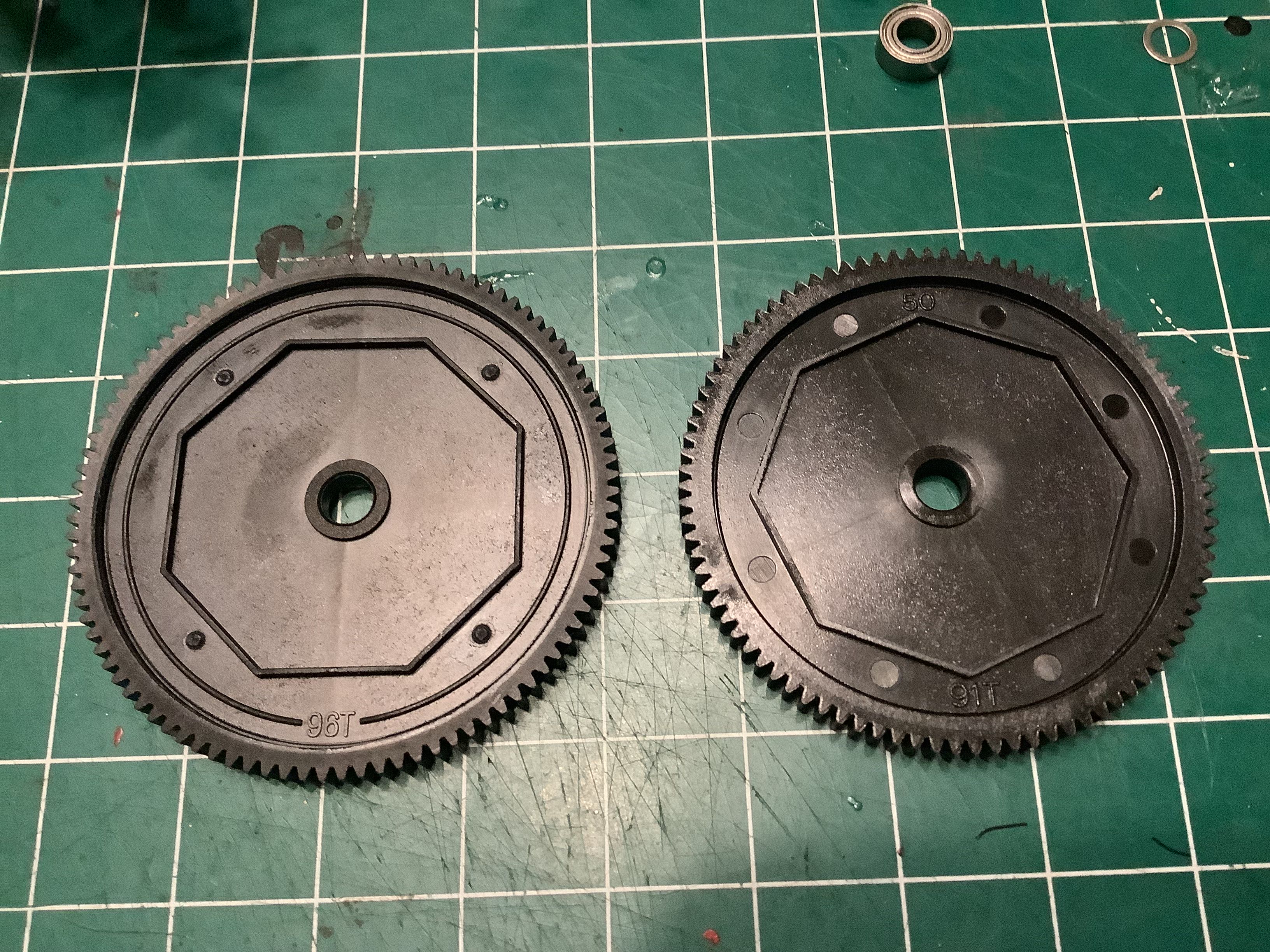
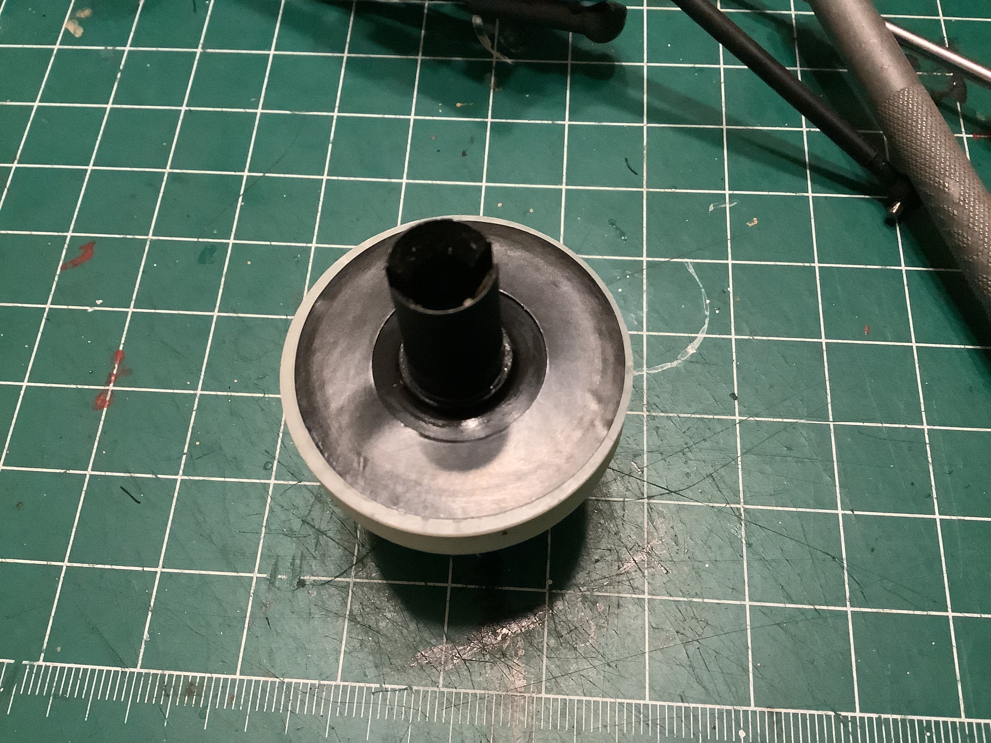
Here is the completed slipper assembly. The original TRF501X used a
48p spur gear with 96 teeth. The World Edition changes this to 91
teeth which will make for more speed. My copy, which had already
been built by someone else, came with the 96T spur so I replaced it
later to stay with the spirit of the special edition. The slightly
different sizes are compared on the right. This kit uses 48p spur
and pinion gears, not the metric 0.6 mod which is unusual for a Tamiya
kit. This is presumably to be consistent with standard racing
pinions.
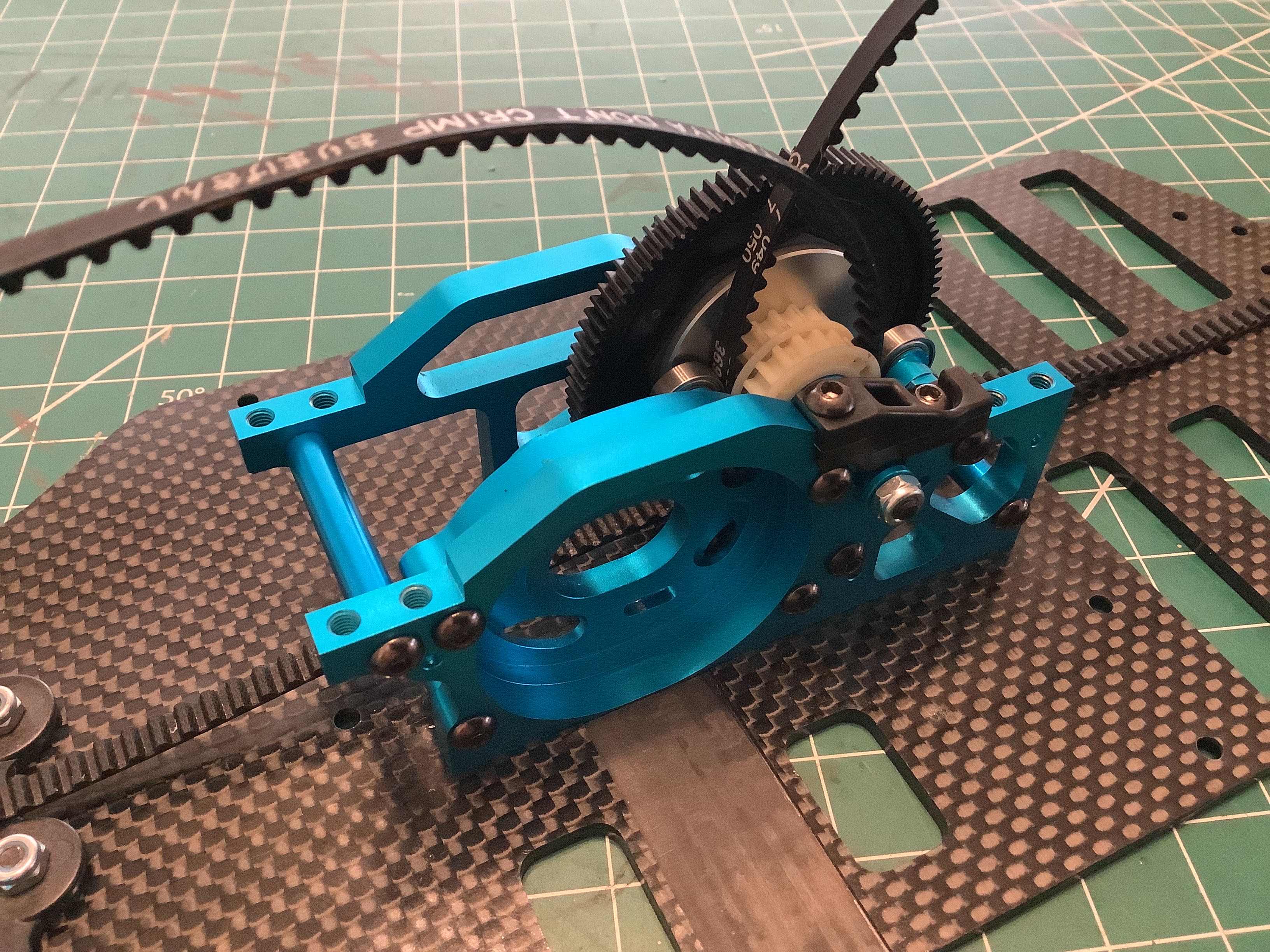
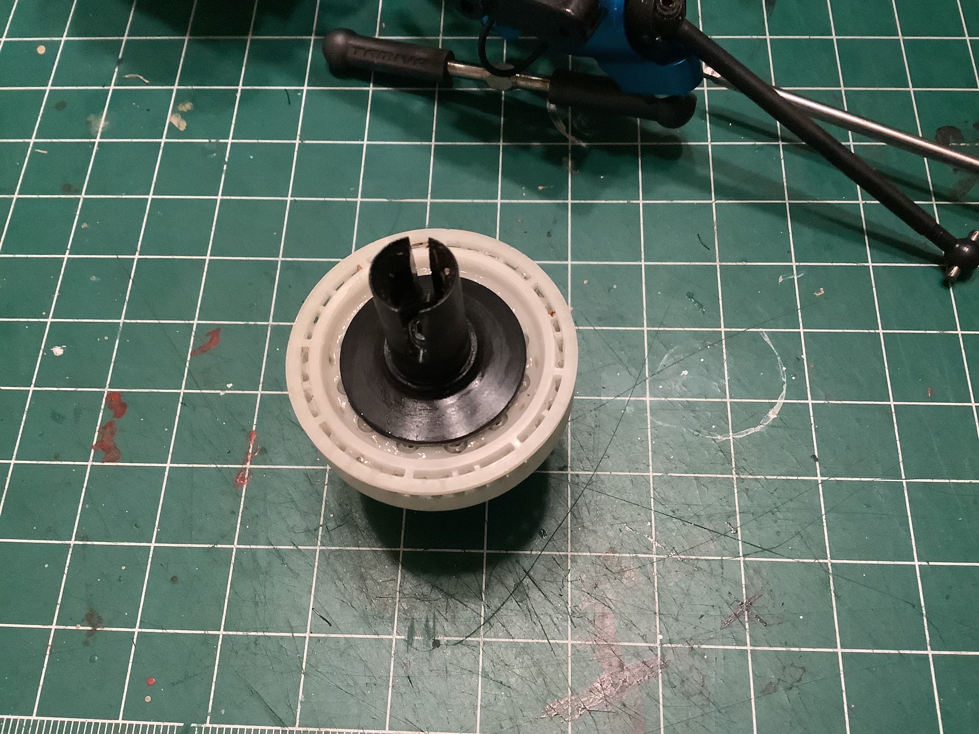
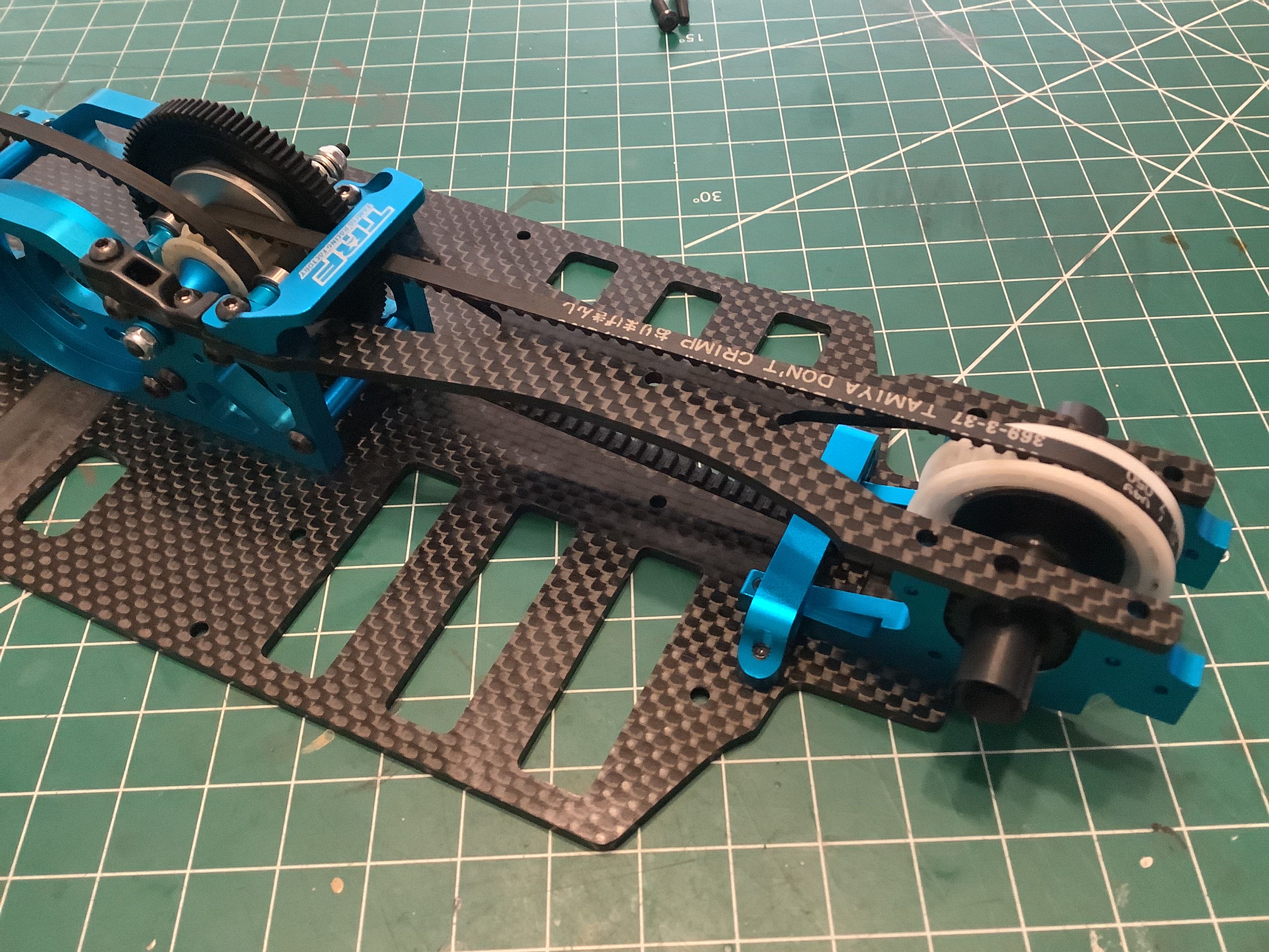
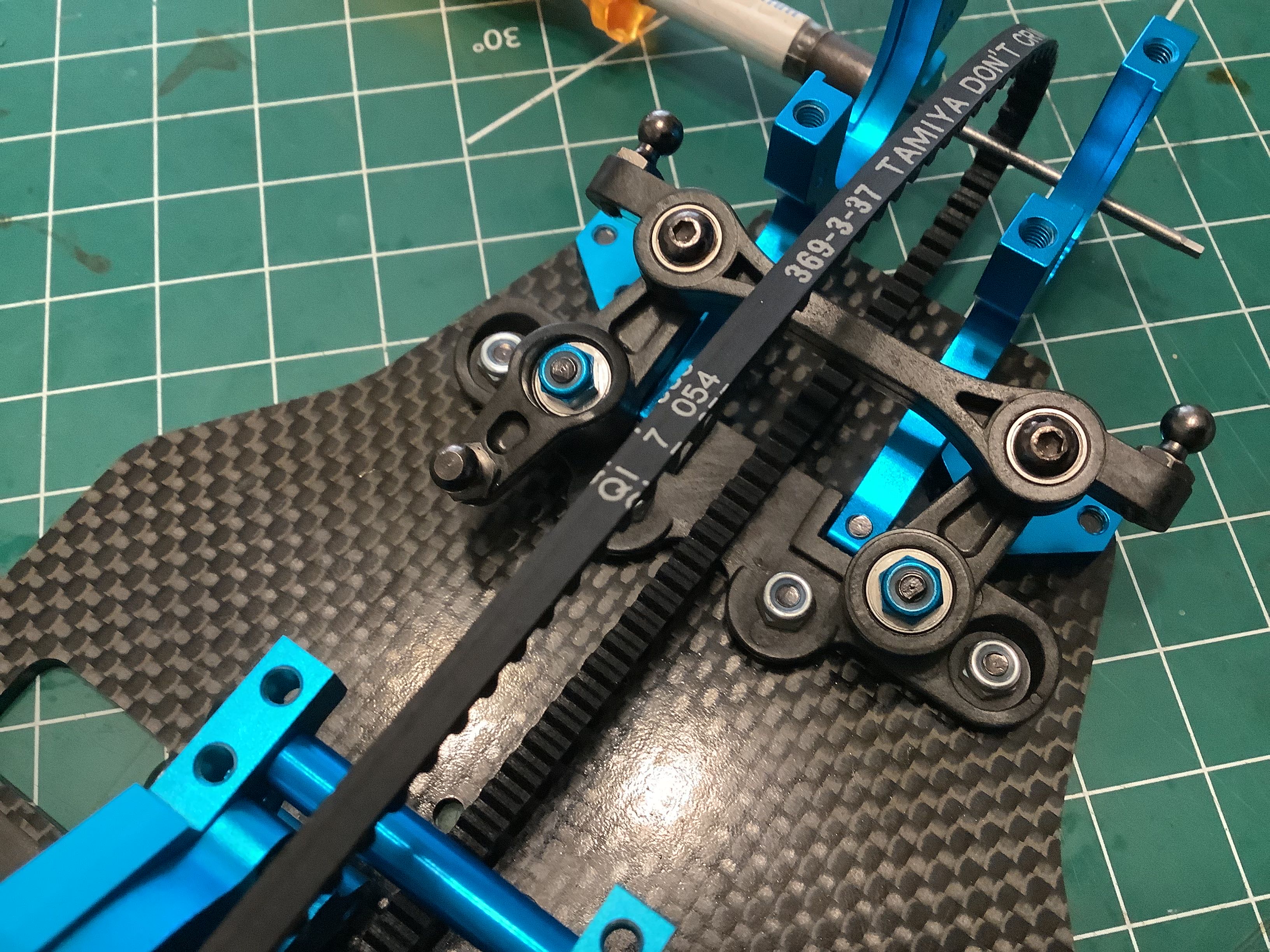
Here I've installed the slipper assembly which requires that the equal
length front and rear belts also be installed. A pair of plastic
bearing caps hold the shaft in place. This is a good time to
adjust the cams which guide the belts.
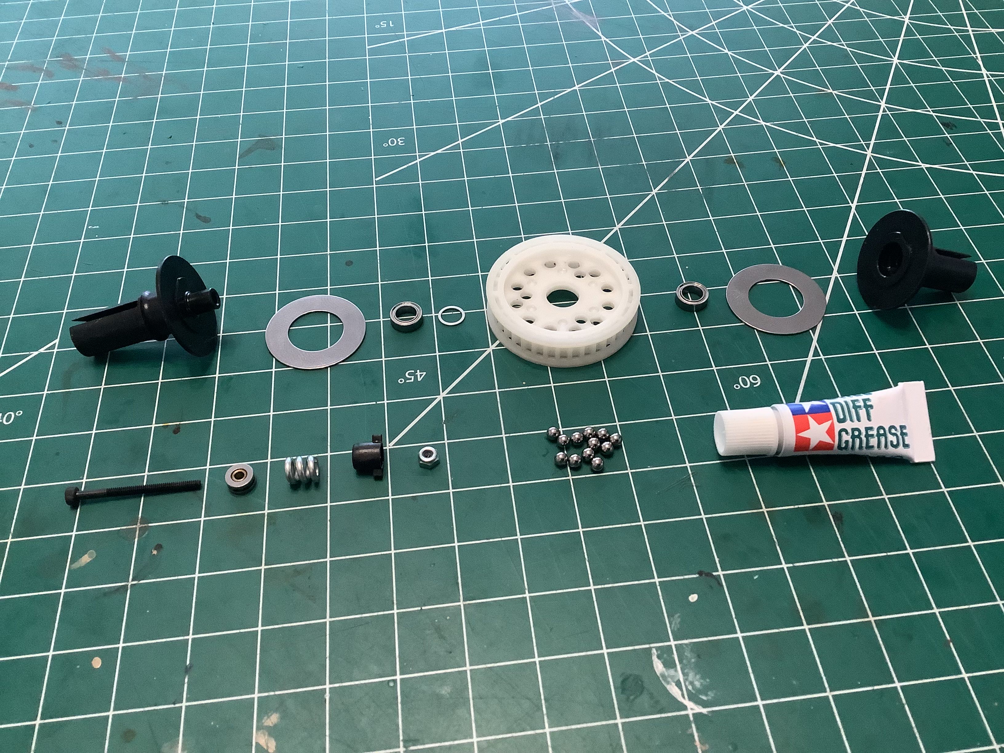
Now I'll build the ball differential. On the original 501X the
front and rear differentials were not the same. The front used a
35T pulley and the rear used a 36T pulley resulting in about a 3%
overdrive of the front axle. Both pulleys integrated a ball
differential with 8ea 3mm balls. The World Edition increases the
ball count to 12 for more strength and standardizes on 37T pulleys both
front and rear, eliminating the overdrive. The overall gear ratio
changed from 12.7:1 to 11.0:1 (assuming a 17T pinion) for 15% more speed from the same motor
rpm.
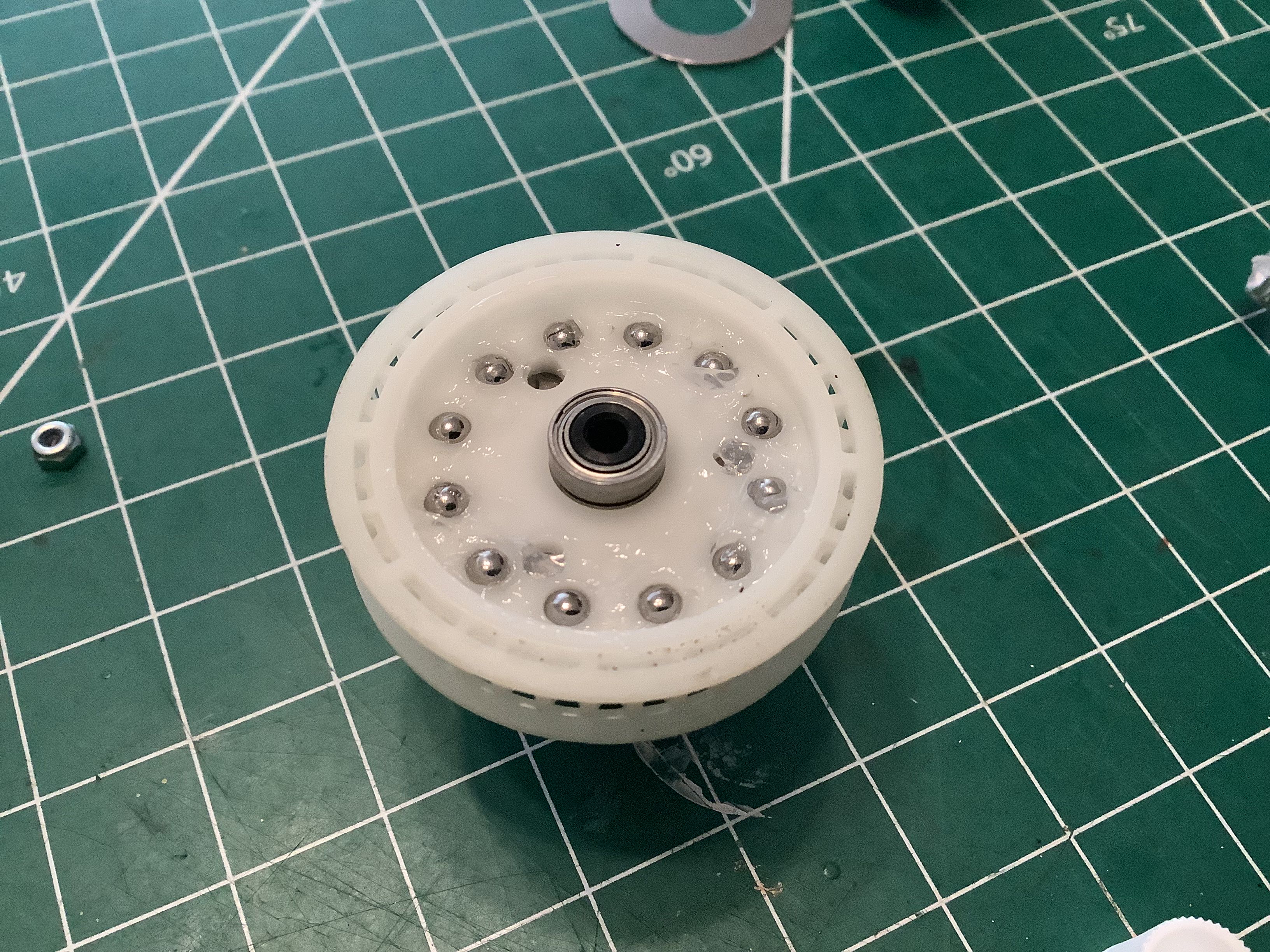
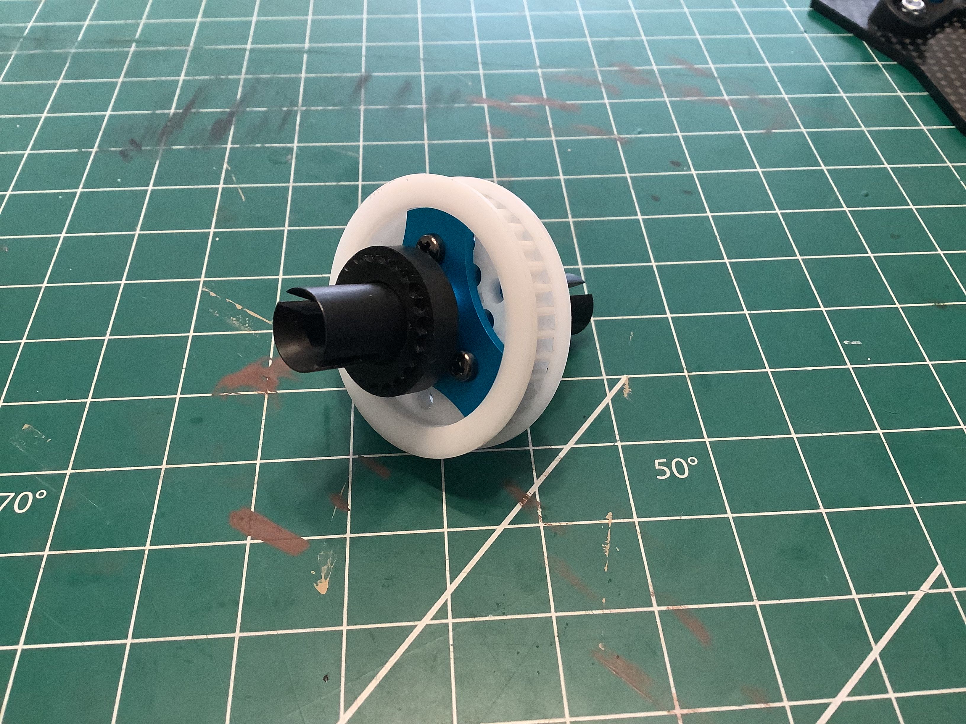
Here is the completed rear ball differential with drive cups
installed. Note that the drive cup is much longer on one side than
the other. This is to offset the pulley from the center of the
bulkhead so it will align with the belt.
I came back later to add these dust shields to the ball
differential. The standard design leaves the balls quite exposed,
especially for an off-road buggy. The addition of the shields
should tend to keep dust and dirt from sticking to the diff
grease. These really should have been included in the baseline
kit; they cost almost nothing.
Now the rear aluminum bulkheads can be installed along with the lower
suspension mount. These attach to the chassis plate with a total
of 6 countersunk screws installed from below. On the right I've
installed the differential into
the rear bulkhead. The rear belt spans between the pulleys. There
are two plastic caps which capture the bearings of the slipper, so in
theory only these and the aluminum stiffener need to be removed to
access the slipper for maintenance. Things are somewhat more
complicated in the rear. The rear upper carbon deck sits over the
top of the differential bearings, so the ball differential cannot be
removed without first removing the upper deck. This design was
changed on the 502 by shortening the upper deck to allow for easier diff
access.
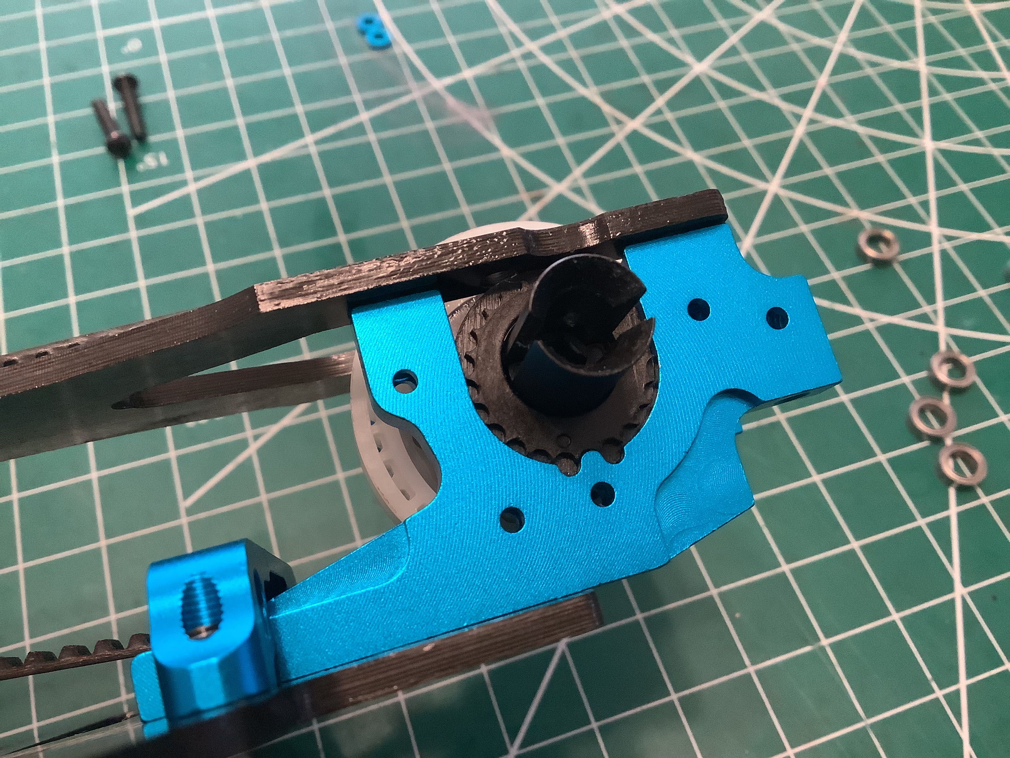
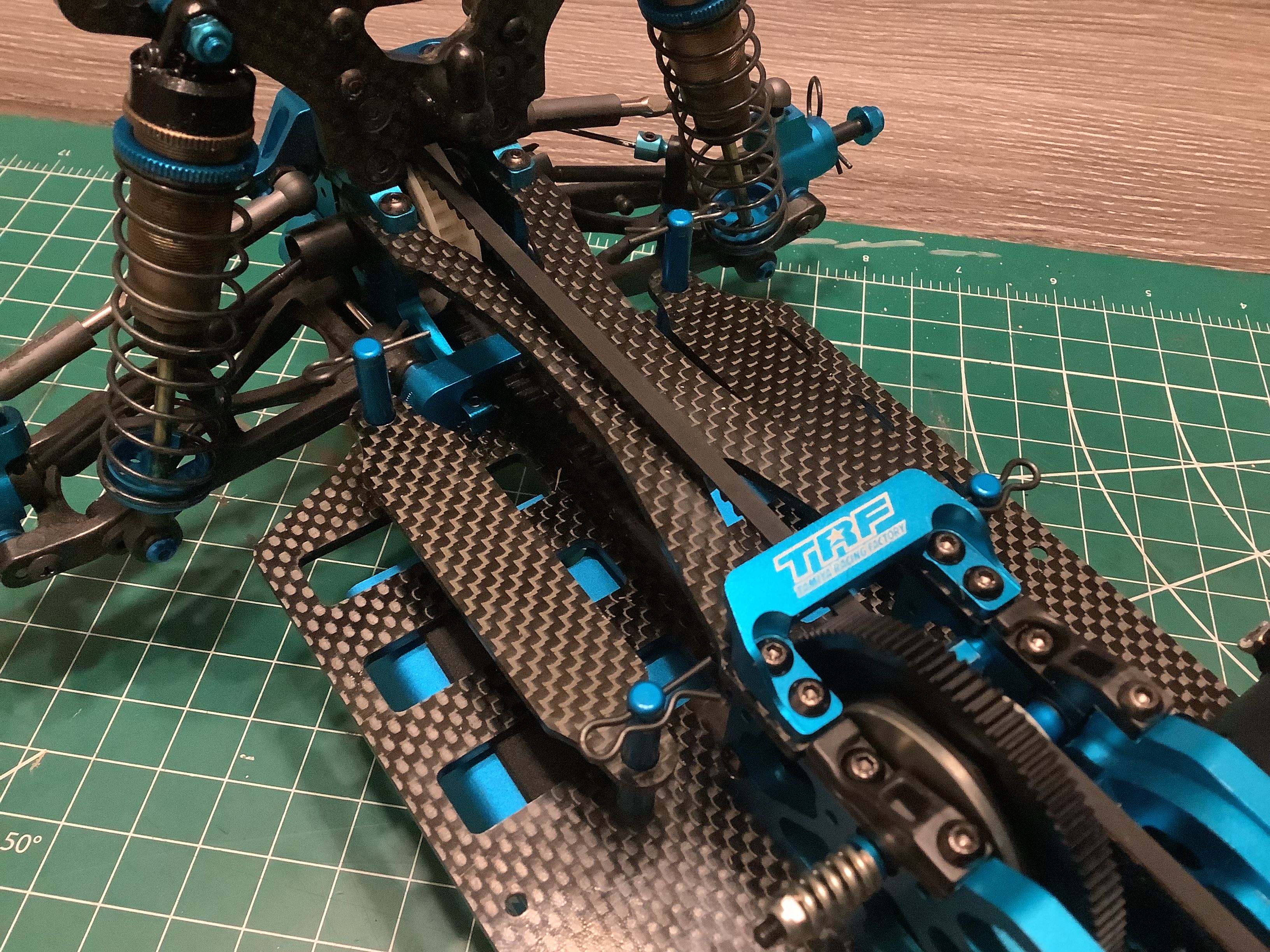
This picture shows the eccentric cam used to adjust the belt
tension. The bearings for the drive cups sit in these plastic
toothed cams which index to the tang on the bottom of the bulkhead as
shown. Rotating the cam to index to the next tooth tightens or
loosens the belt. Incidentally, none of those holes on the side of
the bulkhead are ever used for anything. If I had to guess, I'd
surmise that they are used to support the part while machining.
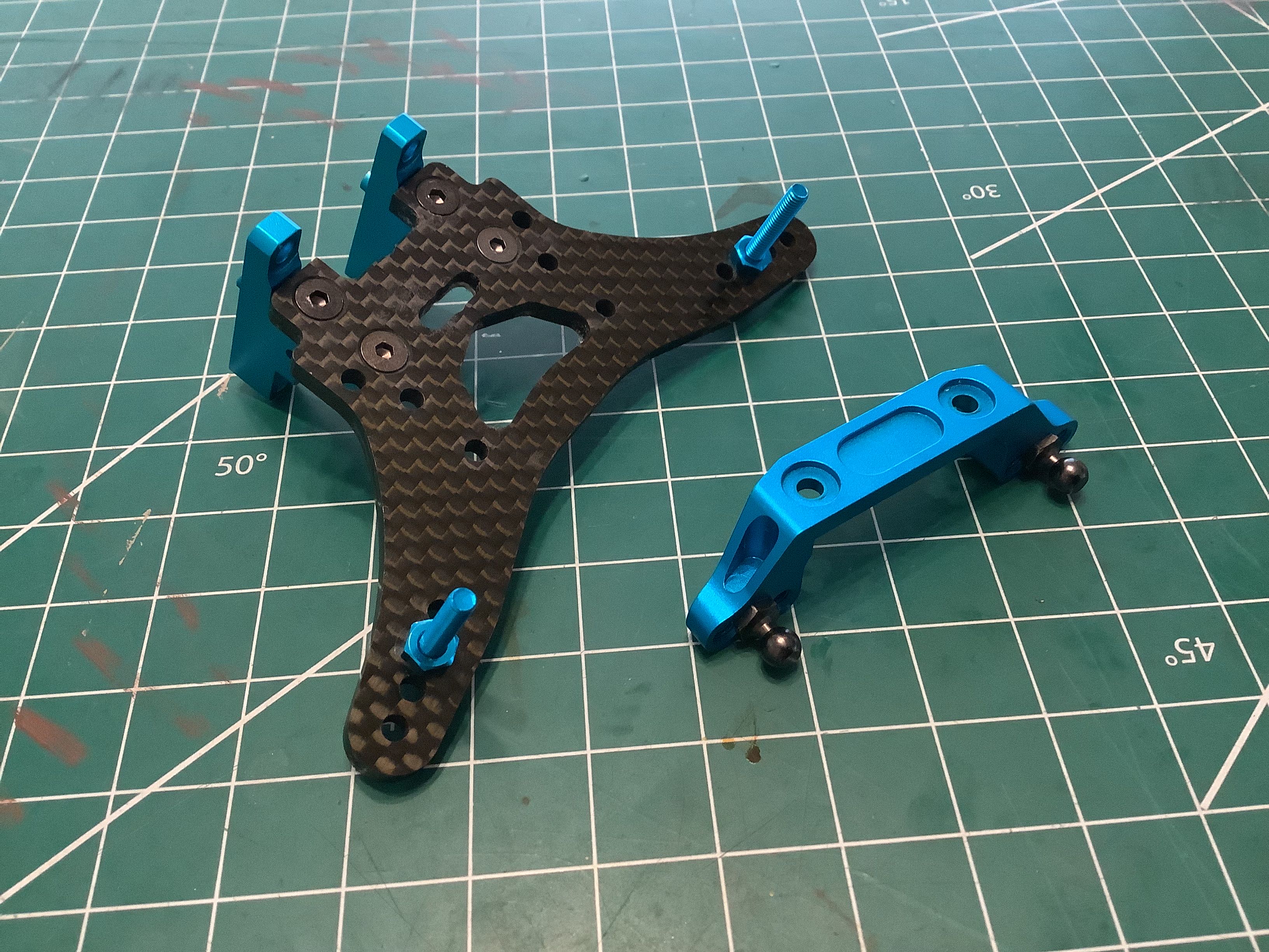
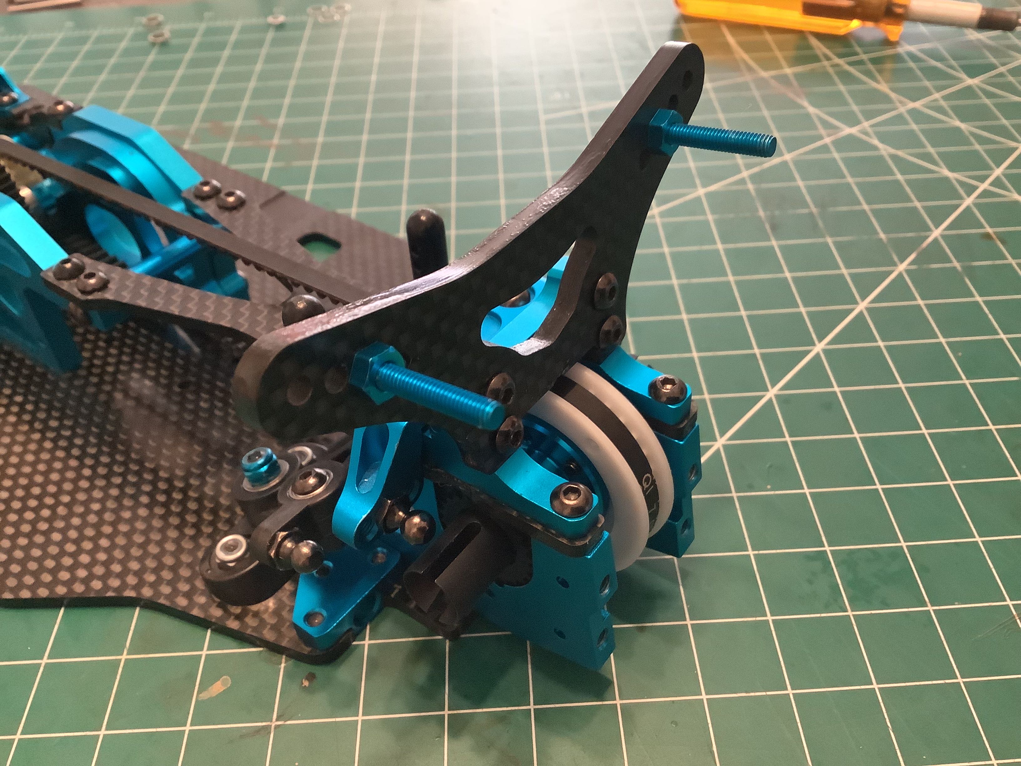
Now I'll prepare the rear shock tower which is a carbon plate attached
to an aluminum bracket. The blue screws shown in the image are not what
originally came with the kit. These have been upgraded by the
previous owner. I suspect they are aluminum which is not ideal for
shock screws which are cantilevered and highly loaded, but they do look
cool. The rear upper arm mount is also shown. Some subtle
changes have been made between the 501X and the World
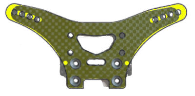
Edition. The picture on the right compares the rear shock
towers. The original part is shown in yellow and the updated part
is shown in carbon laid over the top. You can see that the
mounting holes are the same but the new part moves the shock holes
slightly inboard and down. It also adds two new holes near
the bottom which are not used for anything and a little extra material
beside the mounting holes which does not appear to do anything.
Presumably Tamiya made this change in response to some problem because
they discontinued the original spare part and sold only the newer part
as a replacement.
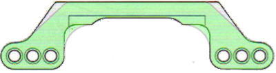
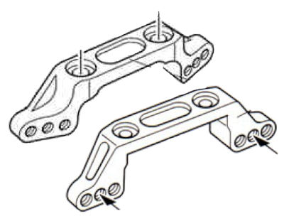
On the left is the same exercise conducted on
the upper shock mount. The green part is the original and the dark
outline is the updated part. It is by no means obvious what problem
this part is trying to solve, but the description uses the word
"strengthened" which would seem to provide the answer. The 3/4
view on the right shows that an additional gusset has been added between
the lower and upper mounting holes which would help a lot with
torsional rigidity. The old part appears to show a shock hole
pattern which is angled, but this is just an artifact of the perspective
used to draw the part in the manual. The true view on the left
shows that all the holes are in a line both before and after the update.
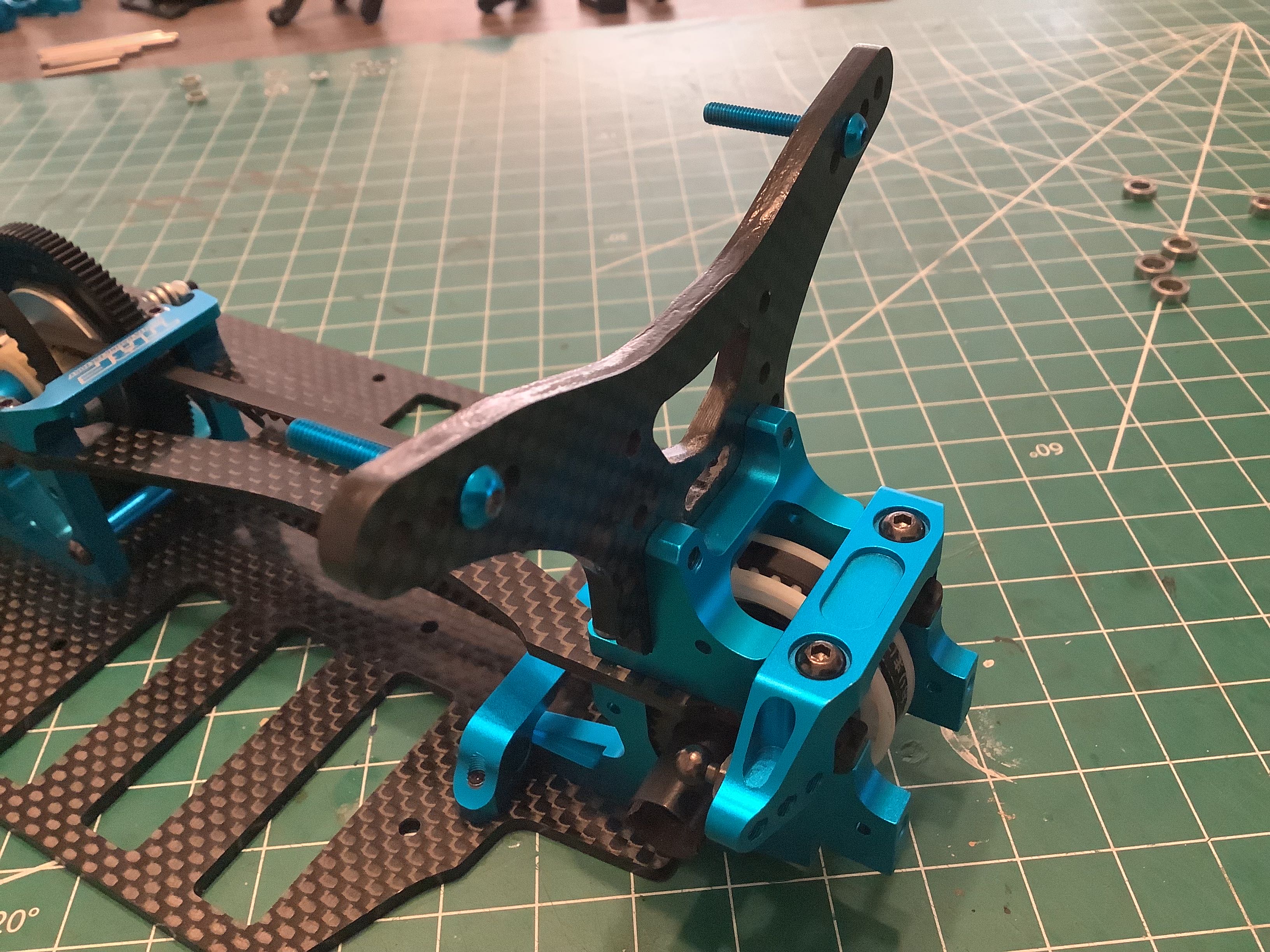
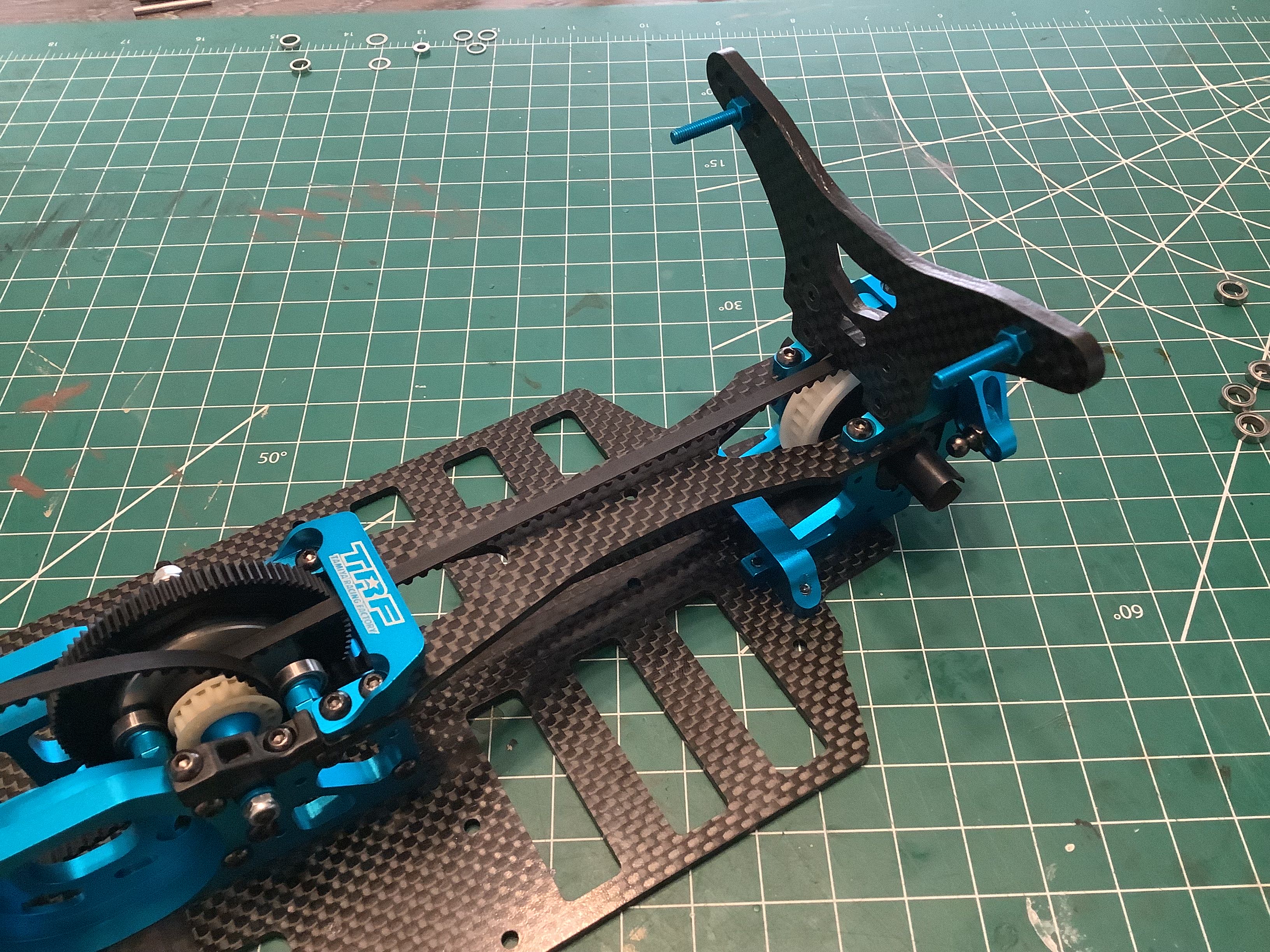
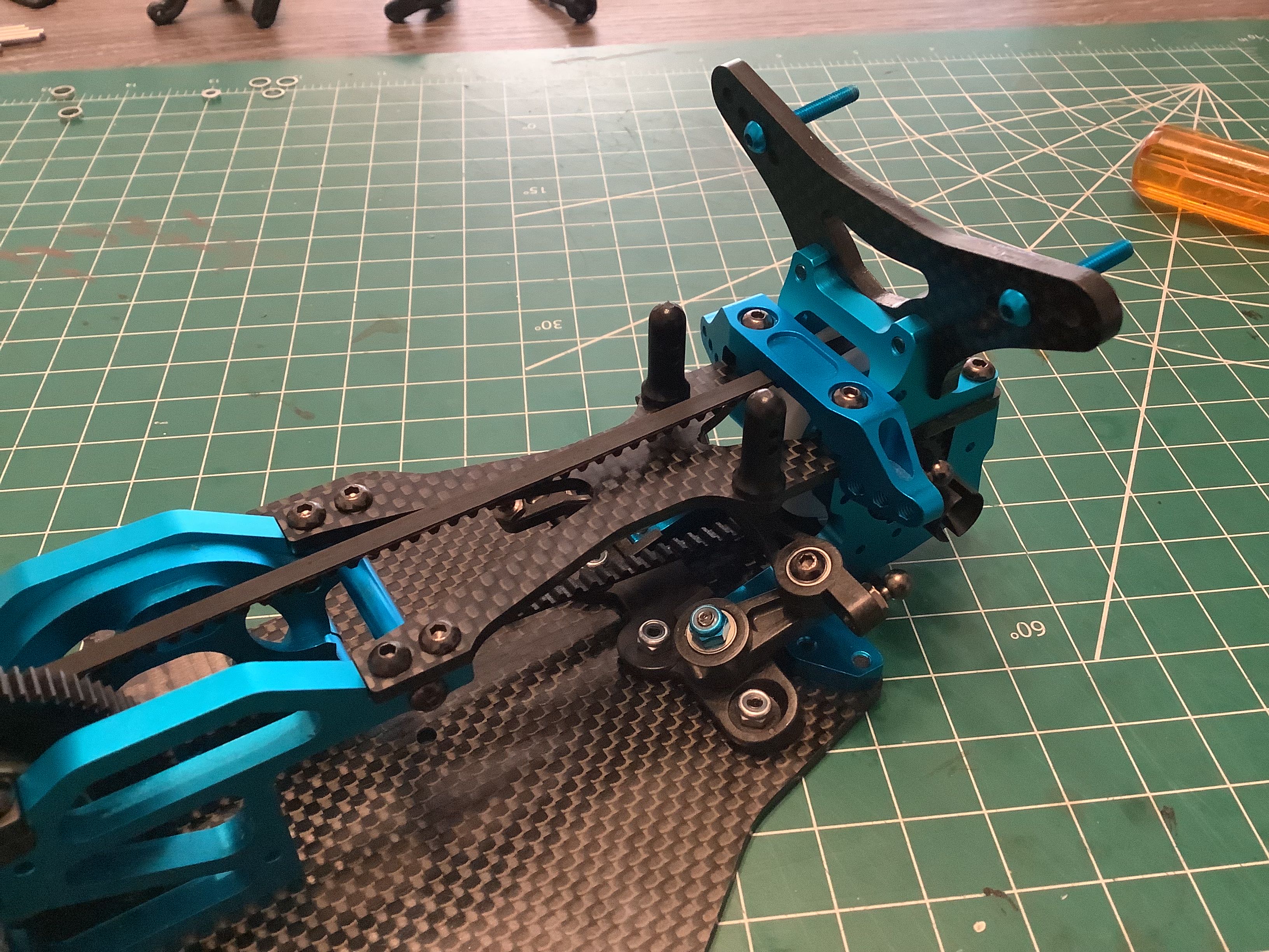
Here the shock tower and upper arm mount have been attached to the the
rear bulkhead. Note that there is no upper bulkhead cover, instead
the tower mount and arm mount span the sides. The bumper which
will be installed later will provide a certain amount of protection to
the exposed belt.
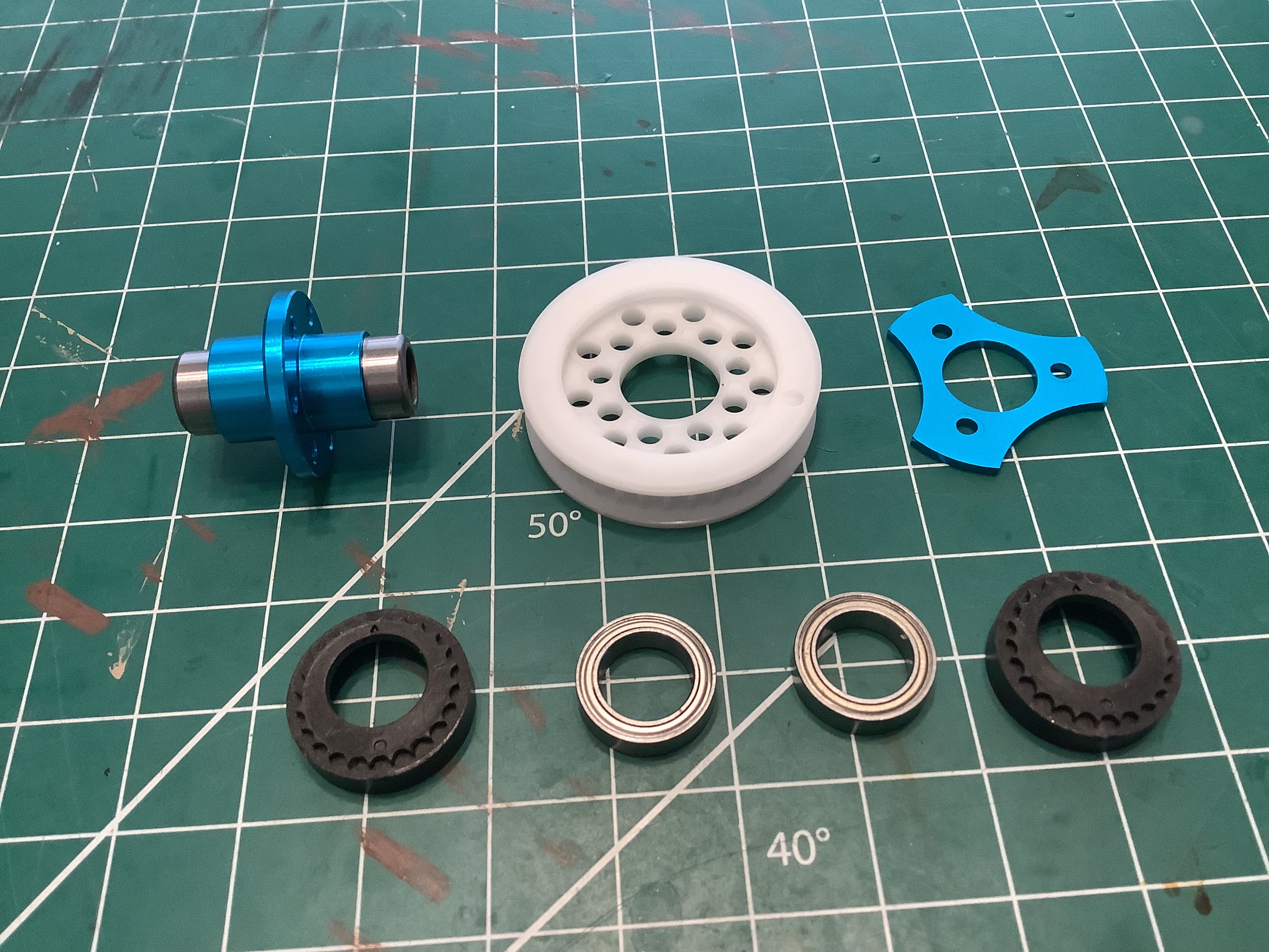
While both the 501X and the World Edition came out of the box with a
ball differential on the front axle, the previous owner of my model
replaced the front ball diff with a front one-way. This is known
to be better for cornering on high grip surfaces while racing, but if
you are just driving for fun like me it is super annoying because you
lose all front braking. Now let's get into some hidden
details. On the far left is the front one way bearing (axles
inserted into it can rotate freely clockwise, but are locked to
the hub counter clockwise. Not so obvious from the image is the fact that
the outer diameter of the hub is slightly larger on the left side of the
flange that on the right side of the flange. The larger diameter
is what fits the inside of the pulley, however the pulley needs to be
installed on the right side to line up with the belt. You can't
just flip the bearing around the other way because then it would lock in
the wrong direction. The solution is the adapter on the
right. It allows the pulley to be centered and securely attached
to the smaller side of the hub. It took me a long time to figure
out what the point of that was. Given that the front one-way
(53951) was made specifically for the TRF 501X, why is an adapter
needed? The part was made for the original 35T front pulley, but
an adapter is needed if you want to use a different pulley. The
previous owner used a 36T pulley from a TA-05 which results in a 3%
overdrive in combination with the 37T rear pulley. I'll be
replacing it with a 37T to get rid of the overdrive. I'd prefer to
go back to a front ball diff, but I don't have the right parts to do
so.
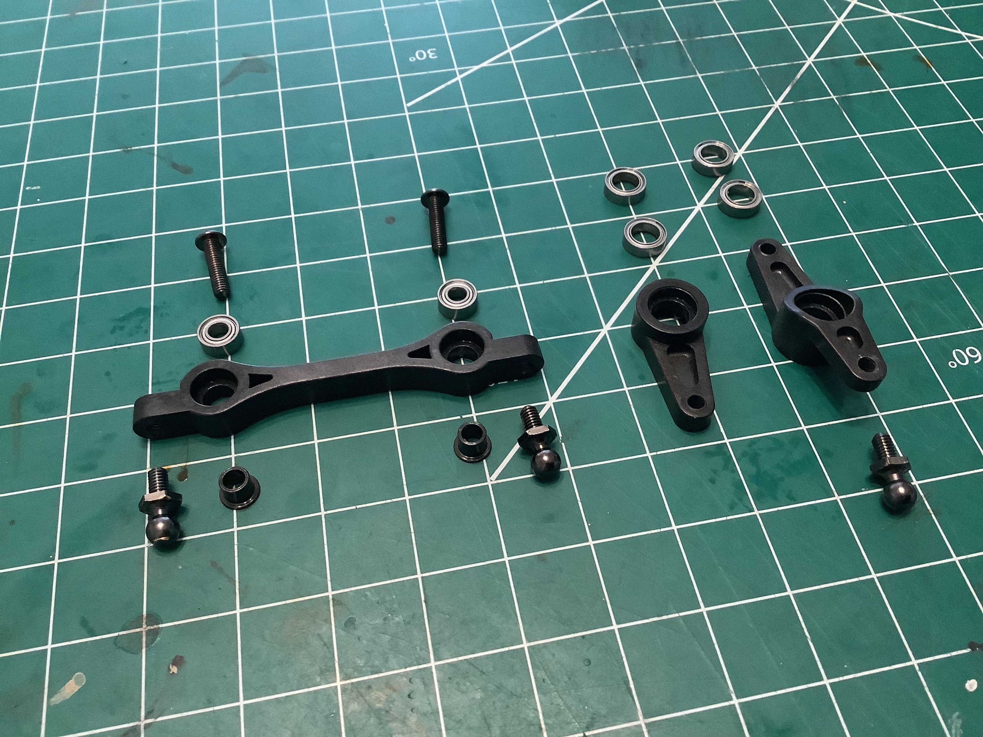
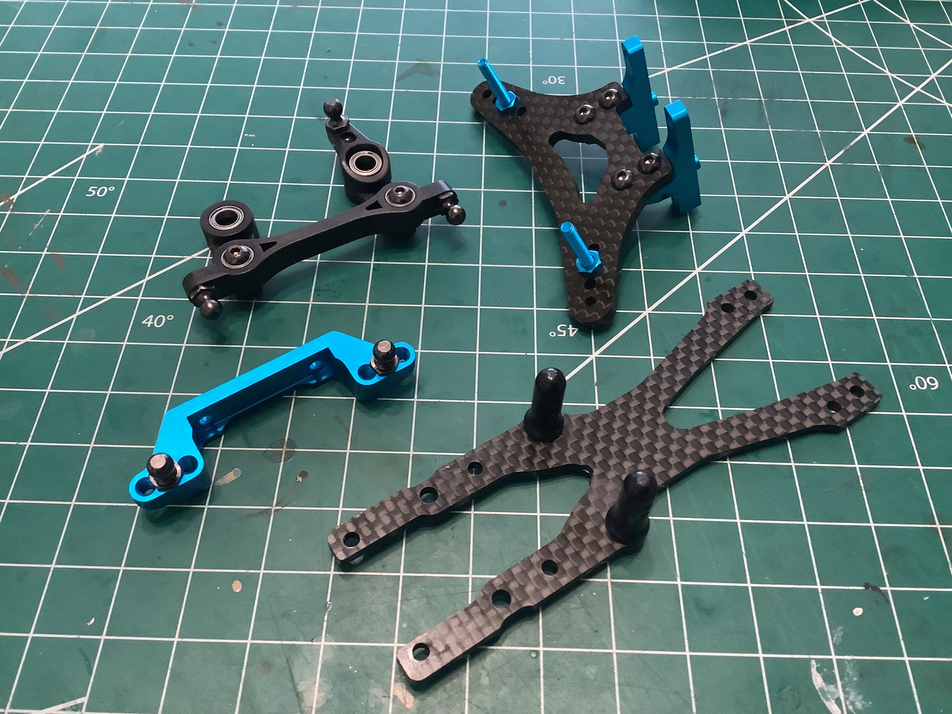
Time to build the dual bellcrank steering. Given the overall
quality of the model, I was a little surprised to see that the steering
bridge and cranks are plastic (aluminum upgrade parts were available). They do use full ball bearings for
assembly though, and I found that the fit was extremely precise.
There is virtually no backlash in the steering. The right hand
photo shows the completed steering assembly, front shock tower assembly,
front upper arm mount, and front upper deck with body posts.
Now the front bulkheads can be installed as shown on the left. It
is interesting how different the lower suspension mounts are than what
was used on the rear. The rear used a single bridging part that
included both ball sockets. The front uses a pair of individual
triangular mounts each with a ball socket. The right hand picture
shows the installed steering system. The blue lock nuts shown are
not original.
Here the shock tower and upper arm mount have been attached to the the
front bulkhead with the upper deck stabilizing everything. You can't tell just from looking that a front one-way is present.
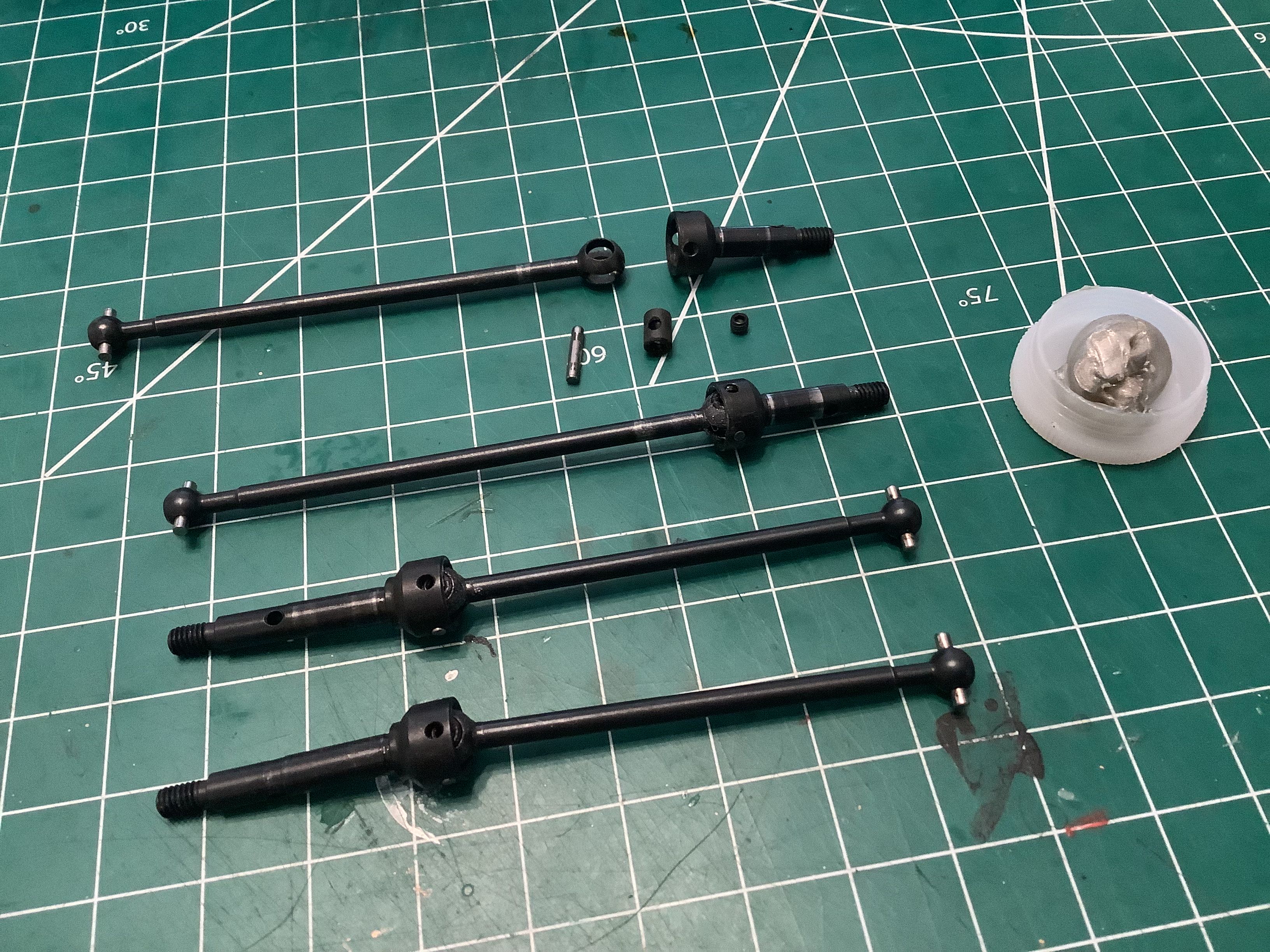
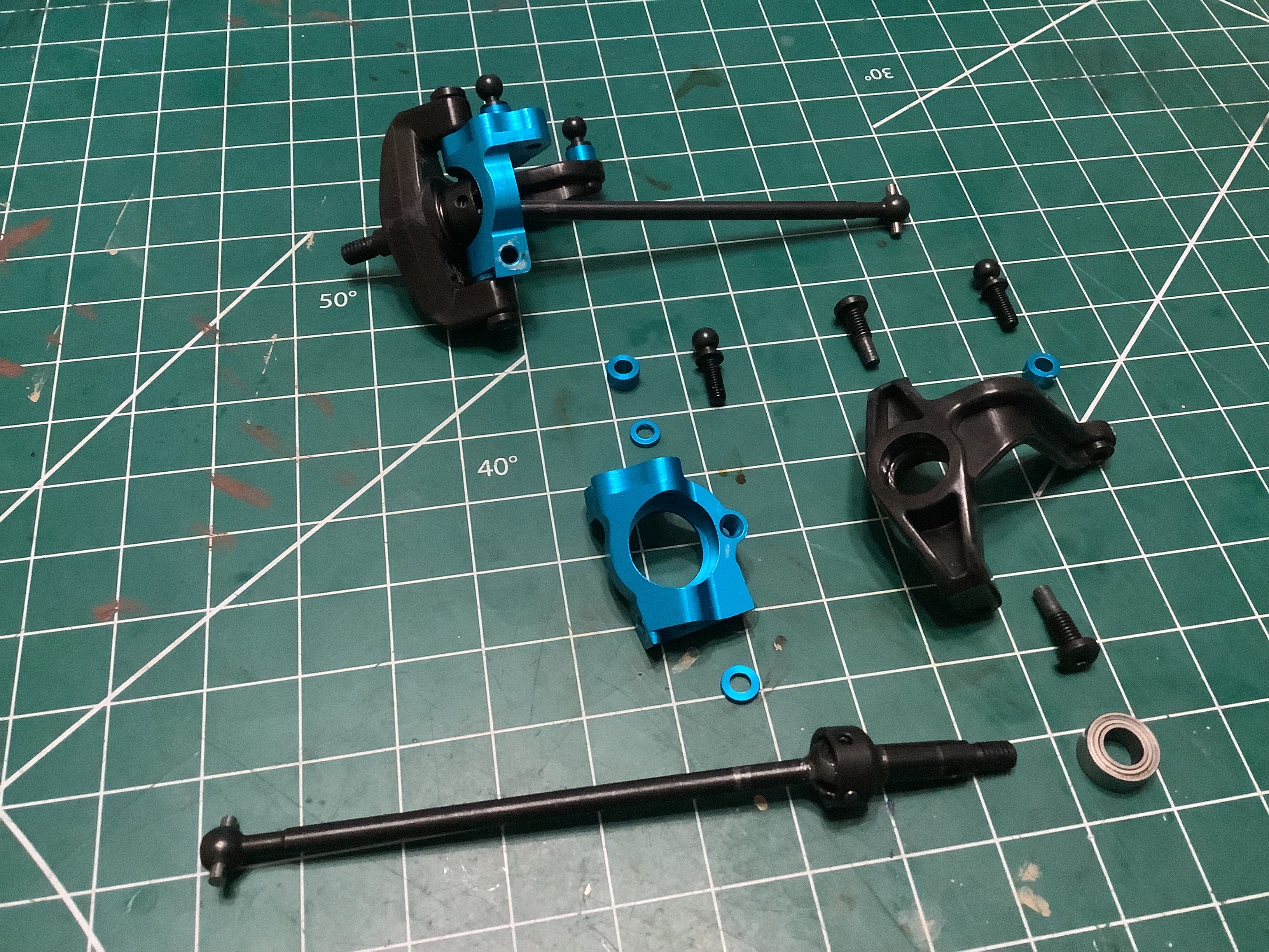
All four corners use CVD style universal axles rather than dog
bones. The rear shafts are 64mm and the front shafts are 78mm
which is a substantial difference in length, but the wheel axles are
also different length so the overall length comes out the same.
One subtle change for the World Edition axles is the length of the cross
pin which has increased from 9.8mm to 10.5mm. This is not even a
noticeable difference visually, but it was presumably done to keep the
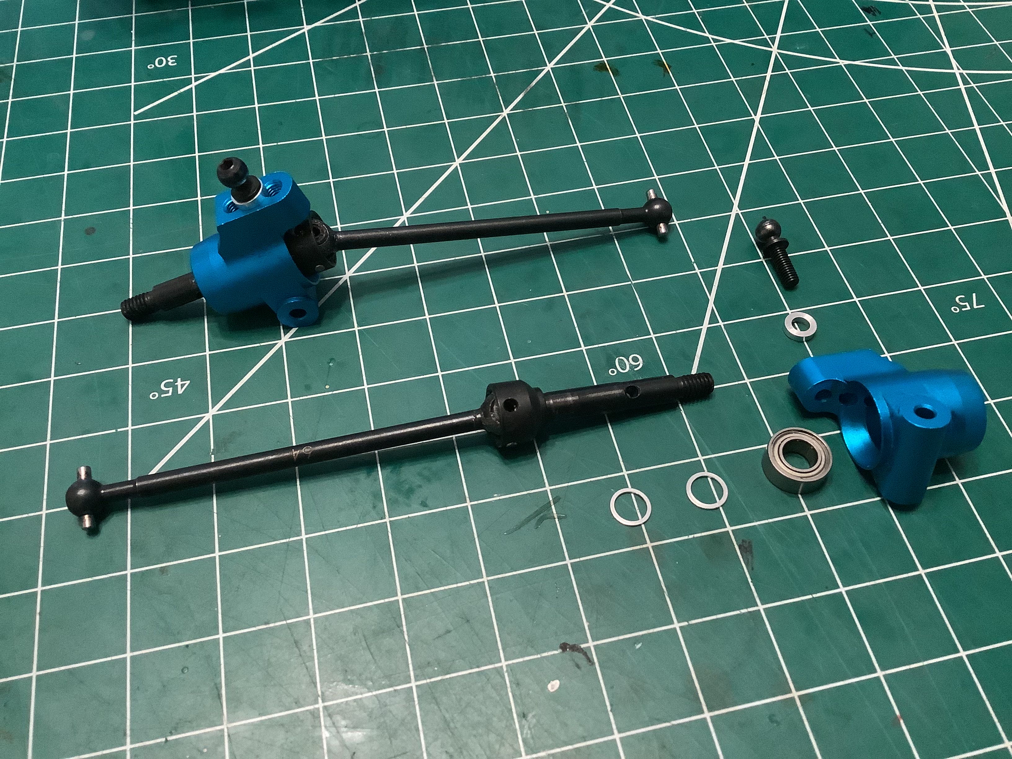
pin from popping out of the cup. The aluminum rear uprights shown
are unique to the World Edition and
replace the plastic parts of the standard 501X. The 5x8mm hex
drive ball connectors shown are also longer and stronger than the 501X
originals.
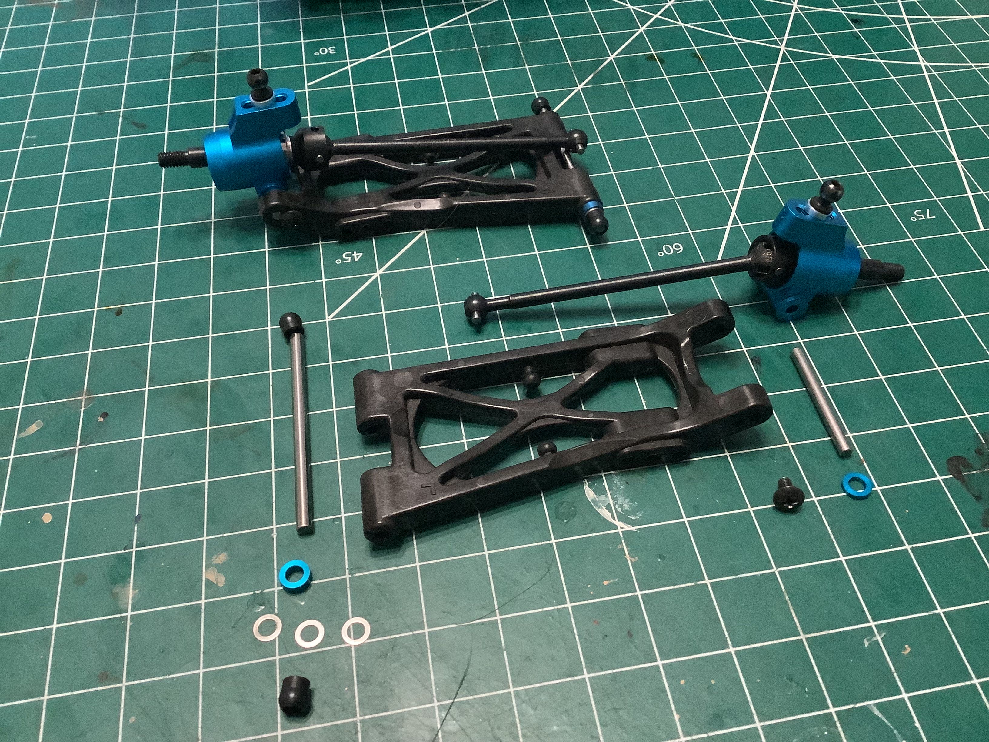
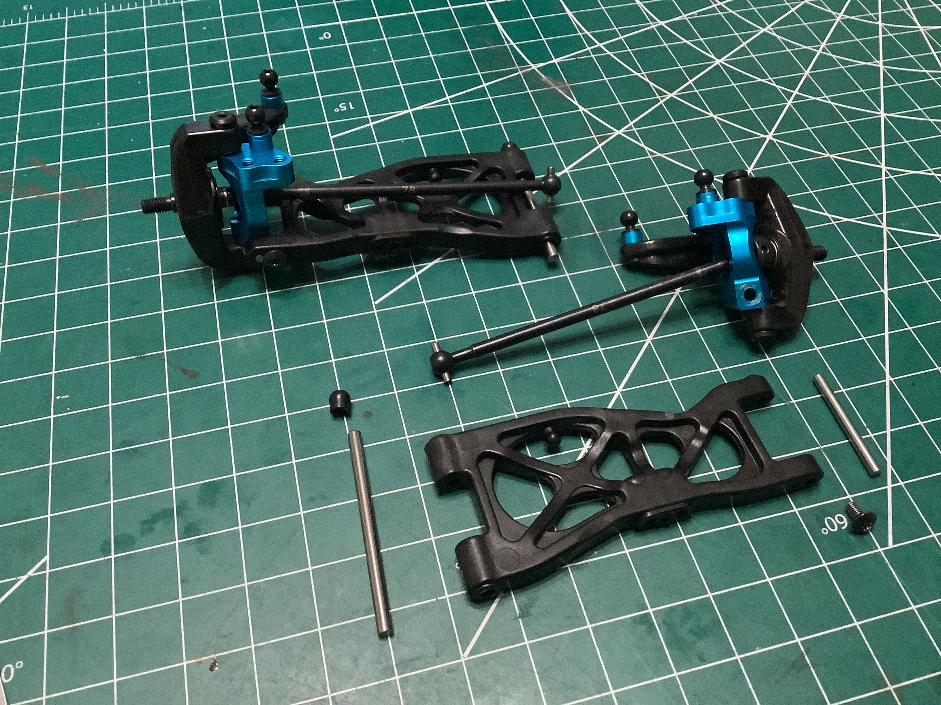
The uprights are installed into the lower arms with captured smooth
hinge pins. The inboard hinge pins have metal spherical balls slid
over the ends to allow for toe adjustment. The difference in
width between the front and rear suspension mounts, if any, controls the
toe angle of the lower arms. In this case, some quick geometry
tells me the angle is about 3°. Additional toe at the axle can
come from unique uprights. These uprights appear to be 0° toe and are
identical left and right. The upper link
turnbuckles shown on the right are not the standard steel Tamiya
parts. I can't tell
for certain since there is no label, but I'd guess that these are Lunsford titanium units.
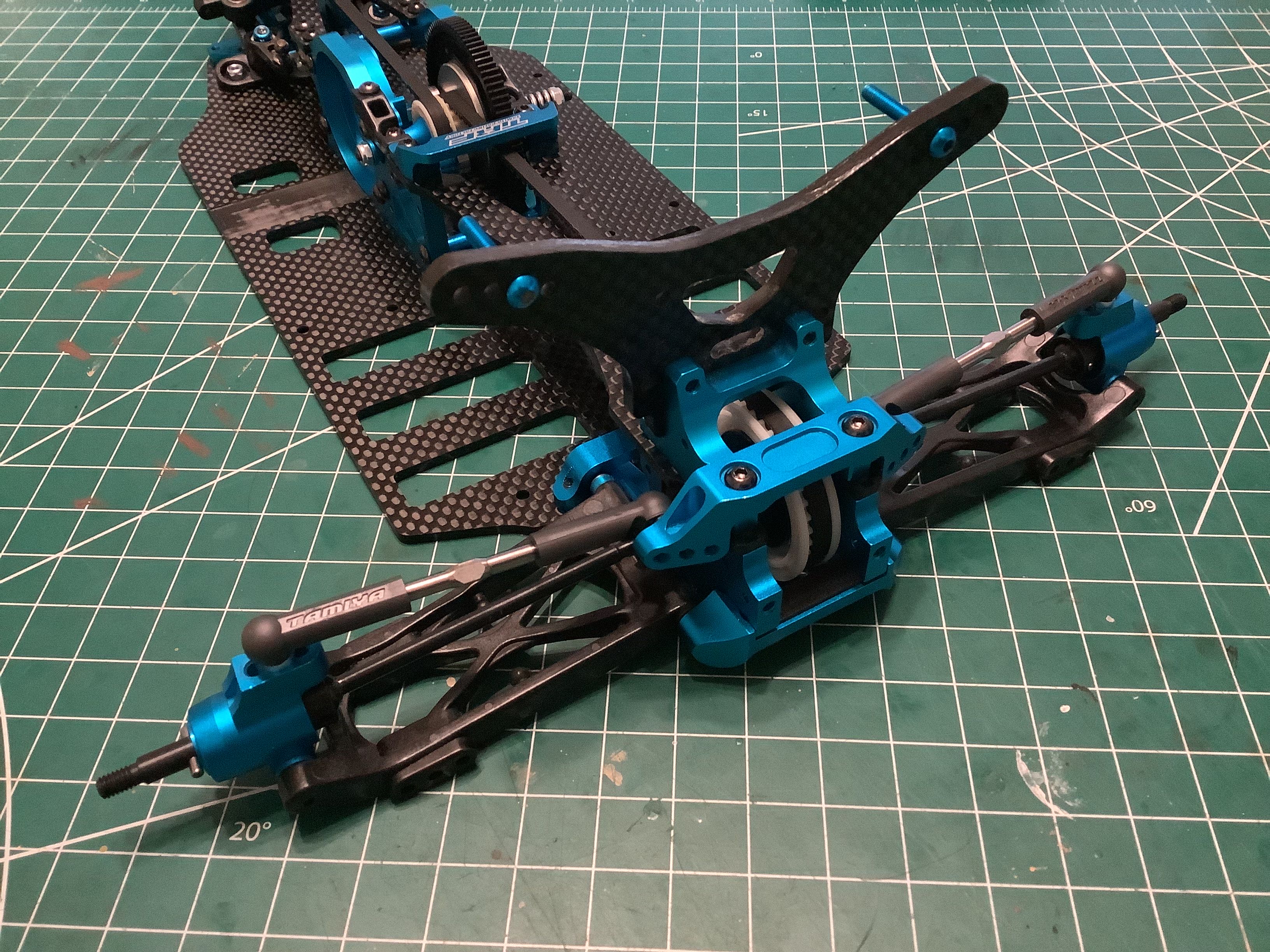
The front aluminum caster blocks are also unique to the World Edition
and incorporate a 10° caster angle, mirrored left and right. The
front suspension arms assemble pretty much like the rears and are shown
at the right.
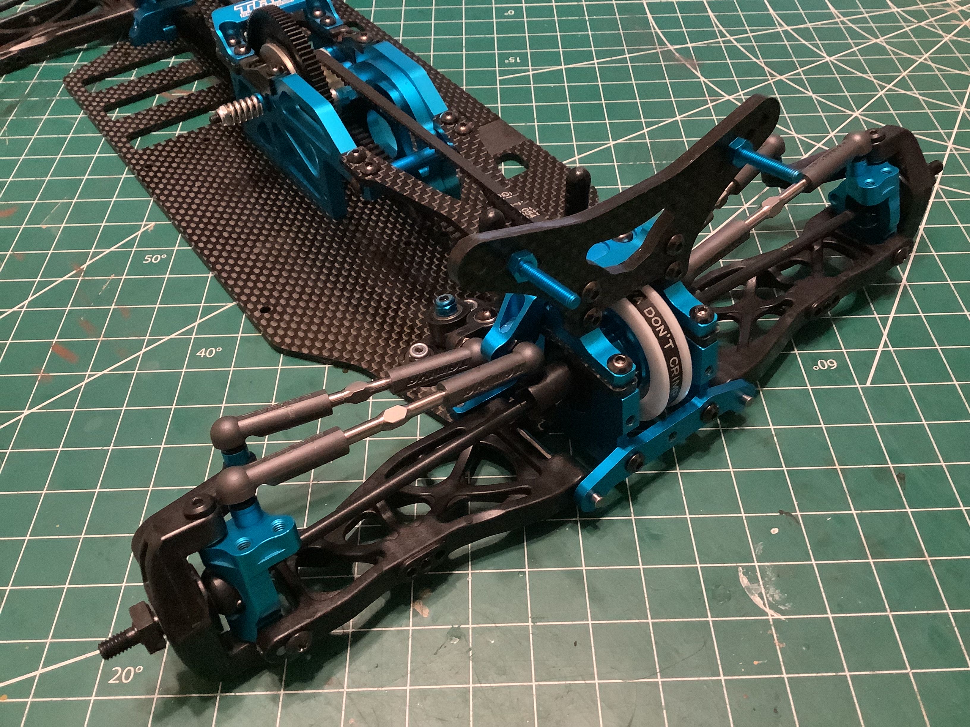
Here the front suspension has been installed along with the titanium
steering links (aftermarket). On the right you can see the rather
conservative front bumper has been installed. It doesn't do much
to protect the suspension from hits, but it does cover the front
pulley. There is no rear bumper.
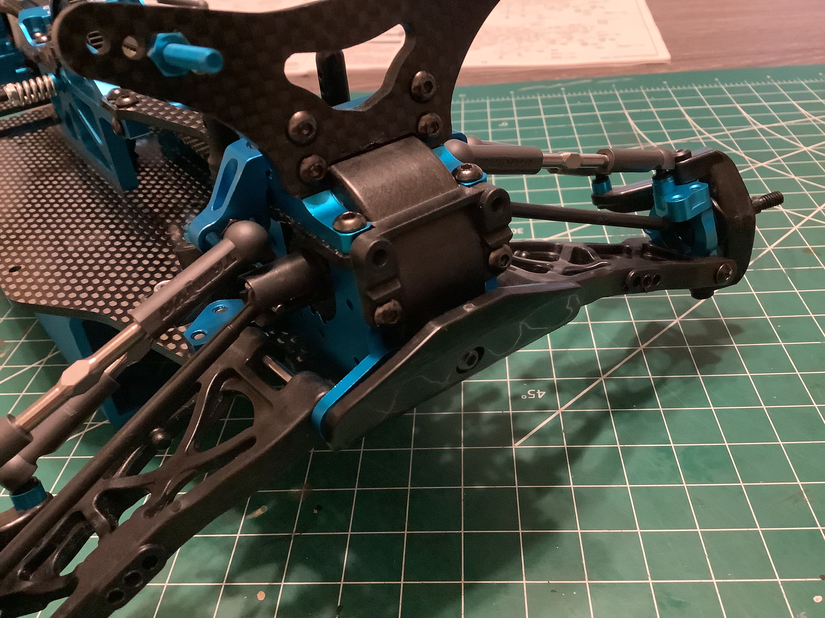
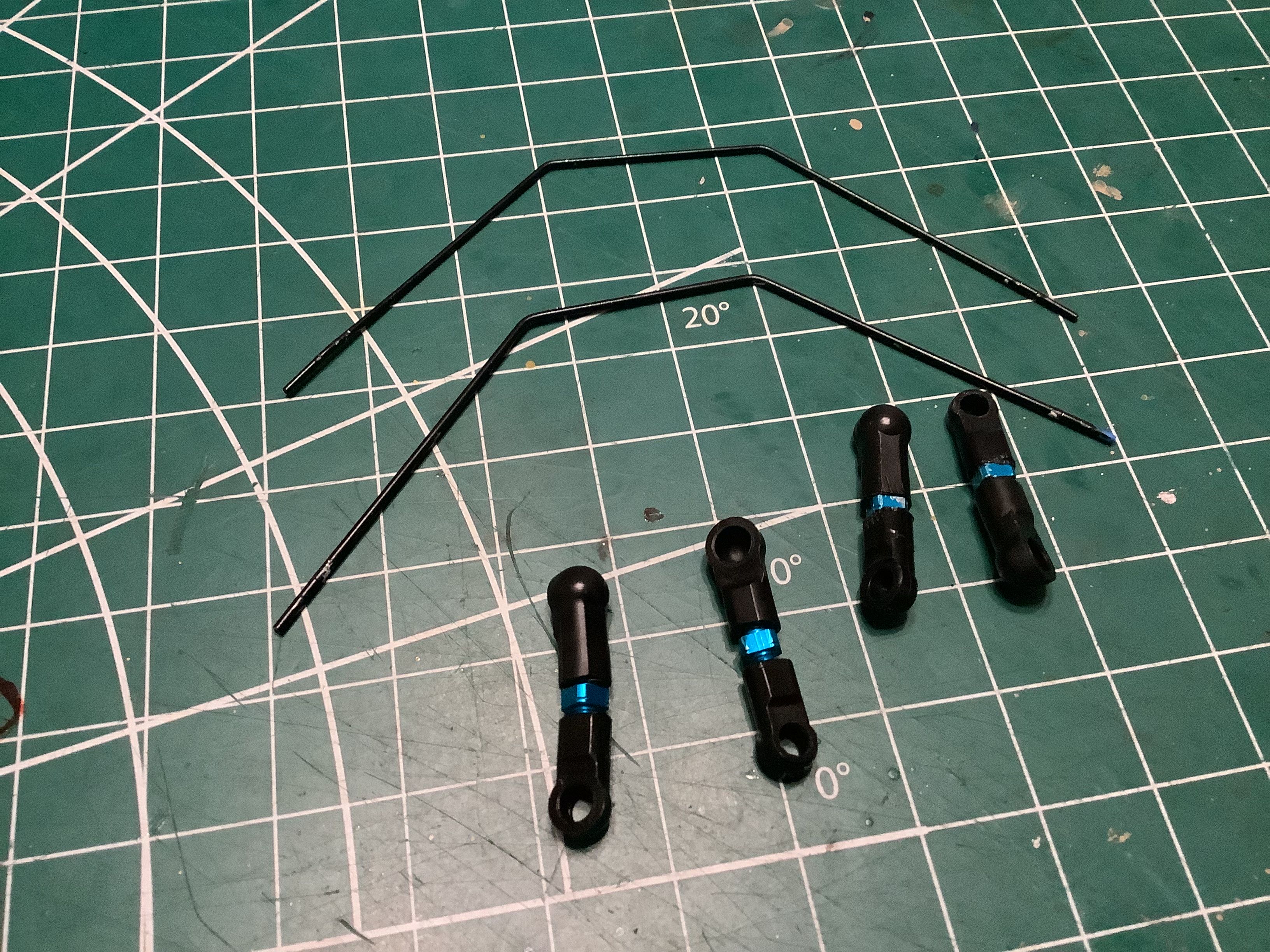
The World Edition includes front and rear sway bars which were optional
with the original kit. The picture on the right shows how one of
them installs, but you'll have to look closely to actually see it.
It pivots on the end of the bulkhead, spans over the drive axles, and
then connects to the lower suspension arms. Those blue aluminum
countersunk screws you see supporting the sway bar are "upgrades".
Strictly speaking they are much weaker than the stock parts, but they
should be plenty strong for this application.
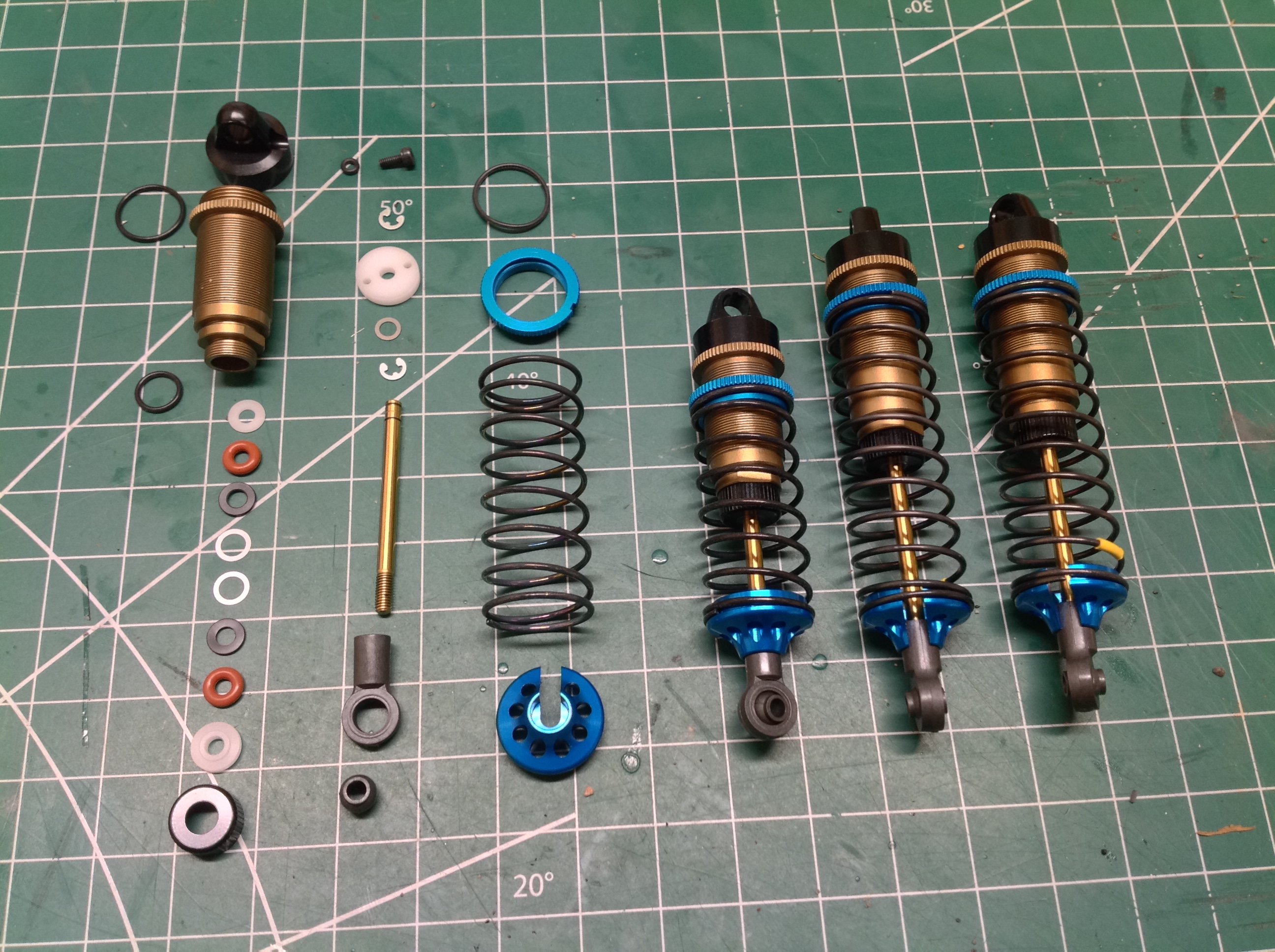
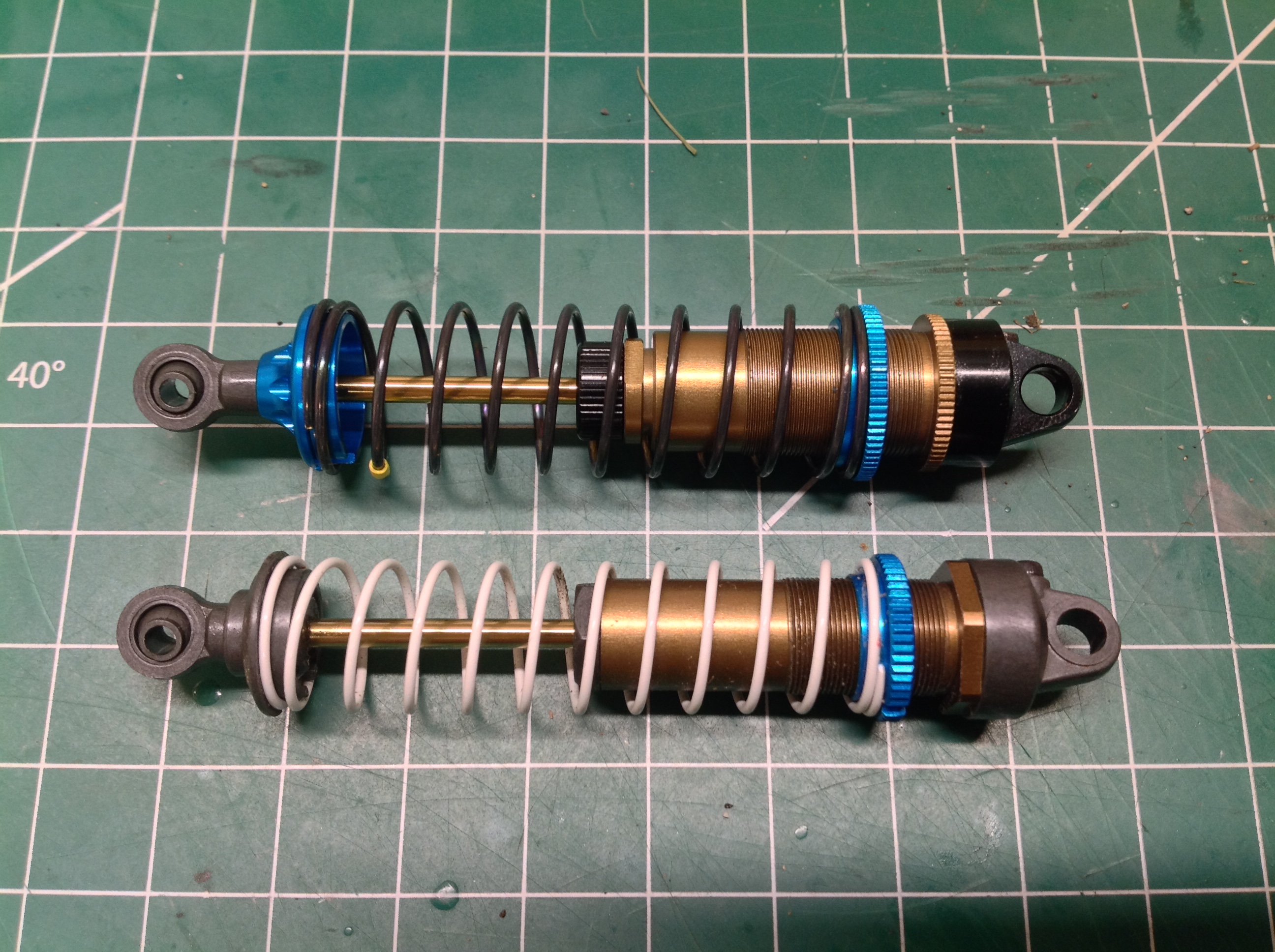
The previous owner of this kit had upgraded to "big bore" shocks from
the TRF 503X to replace the original shocks. In case you are
wondering,
these have a 12mm bore instead of 10mm. That doesn't sound like a
lot, but it results in 44% more volume. The old and new shock
types are compared on the right. These shocks build exactly like
the smaller set, but you may notice that they now include aluminum
spring perches as well. Compared to the shocks included in the
original 501X, the World Edition upgraded to Delrin pistons. The
pictures shown here are actually from my TRF 201 build because I didn't
want to tear down and rebuild the shocks that came with this model.
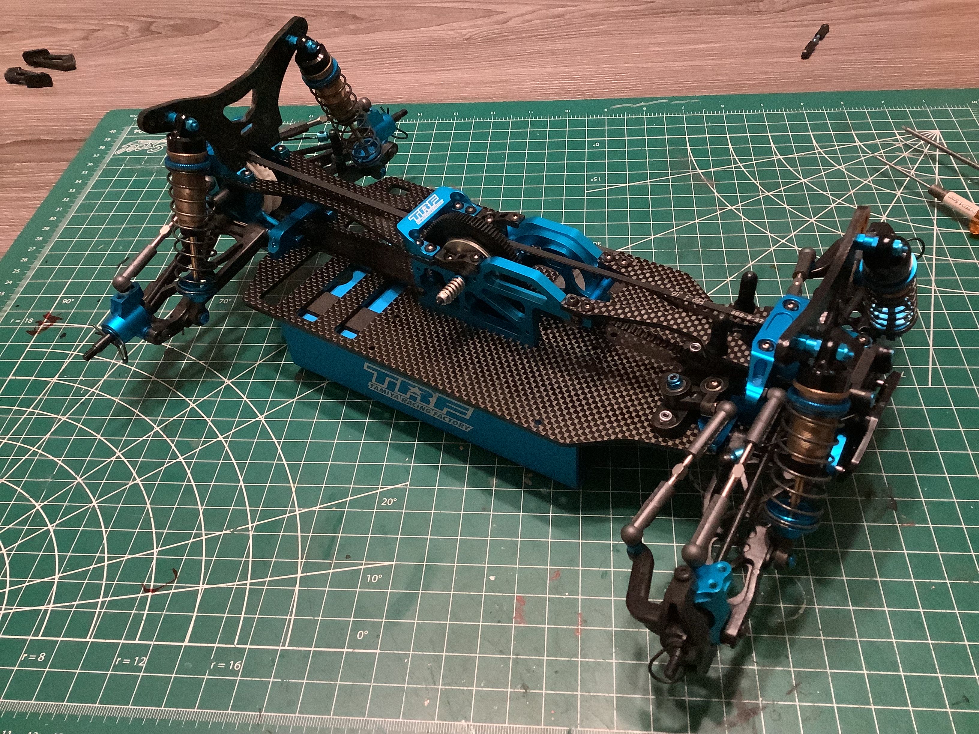
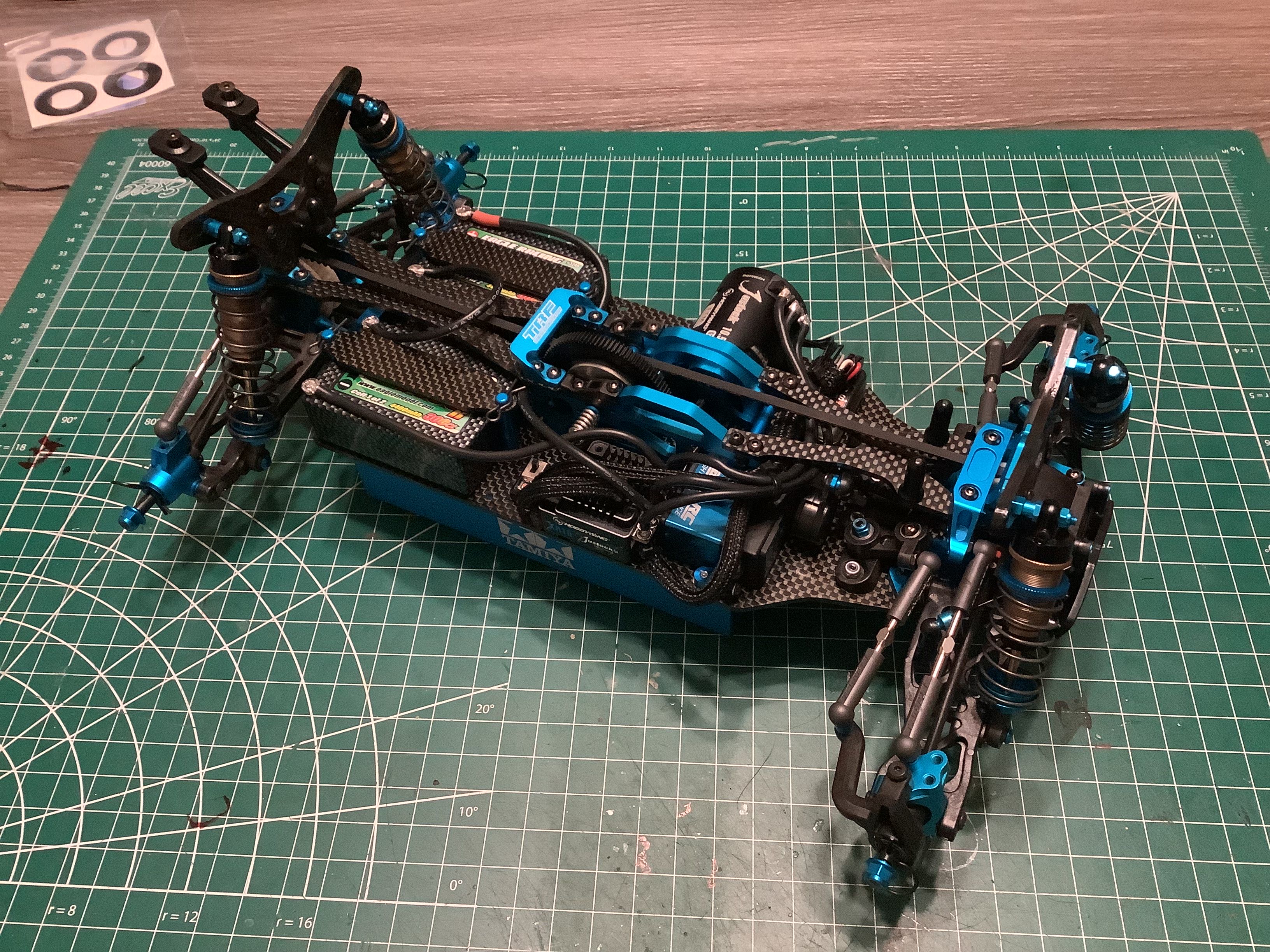
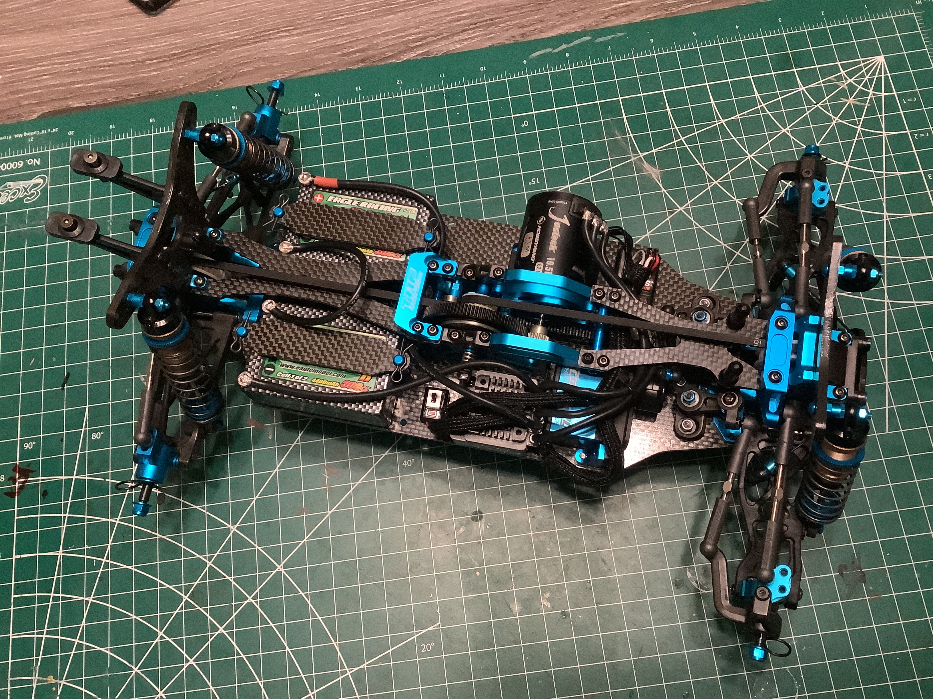
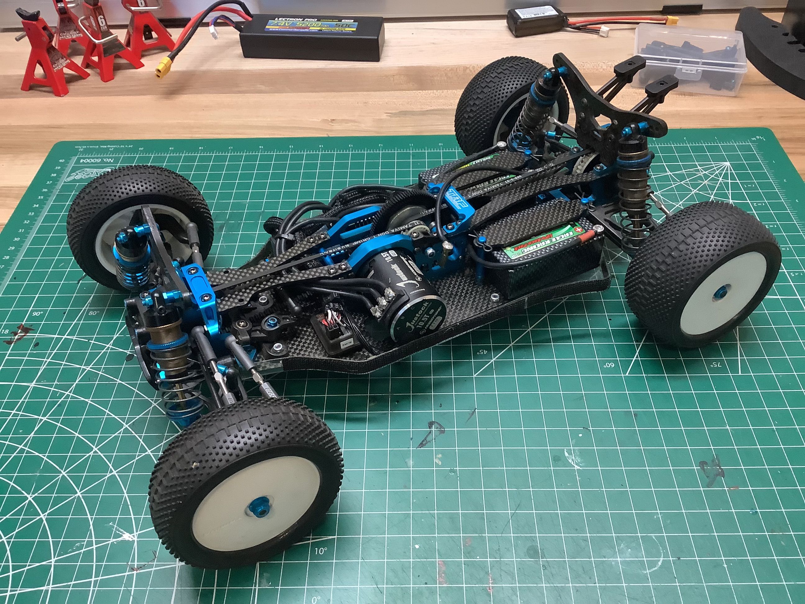
The installation of the shocks pretty much completes the rolling
chassis. I can stare at this picture for a long time because of
the beauty and quality of the chassis parts. On the right I've
also installed the carbon plates which hold down the saddle pack
batteries.
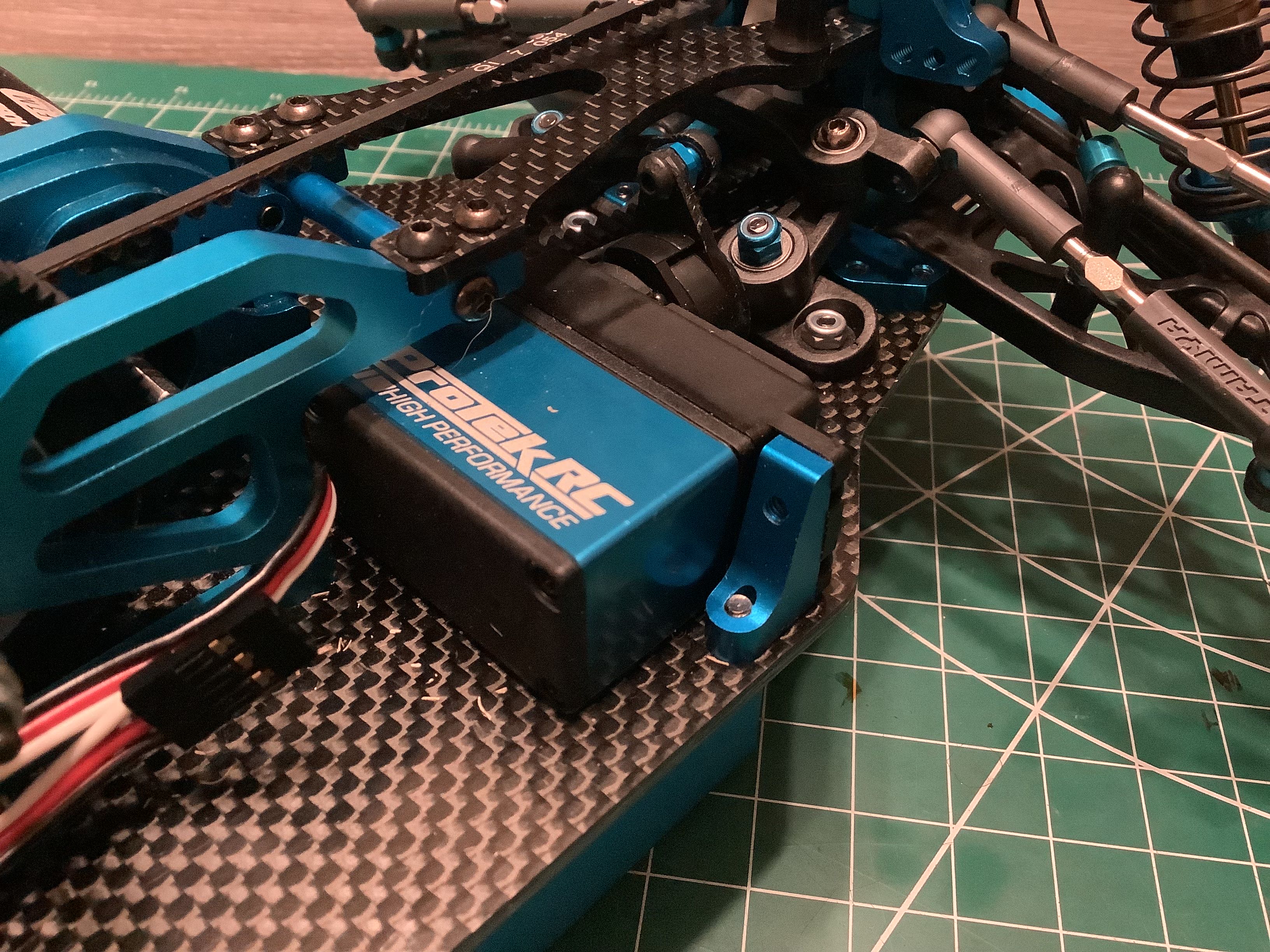
I decided to use a high speed Protek steering servo with an anodized
blue aluminum case to match the rest of the chassis. The servo
mounts you see in the picture are not original. The kit uses thin
plastic mounts, but the previous owner upgraded to these much nicer
aluminum mounts from the TRF 416. On the right I've installed my
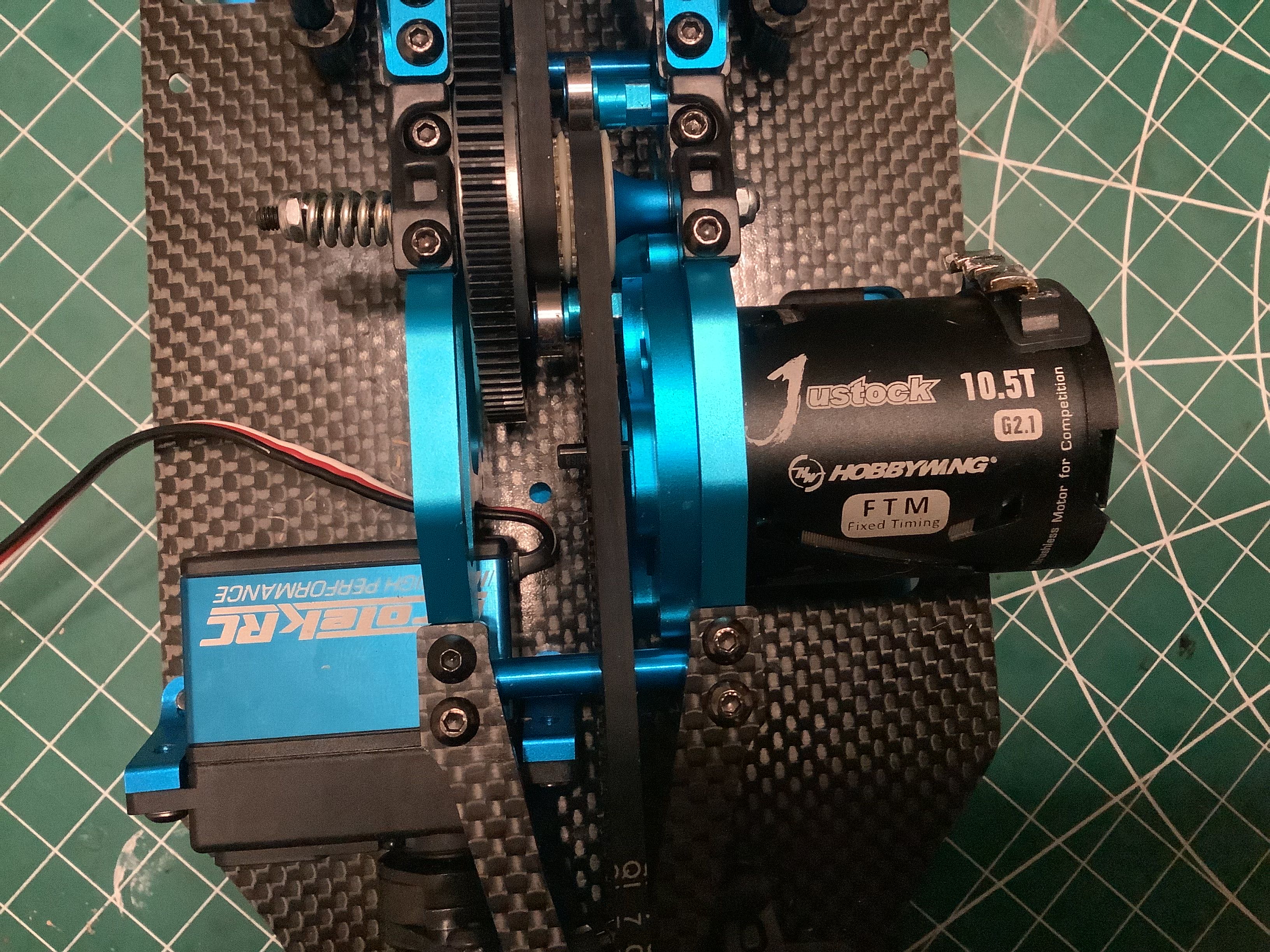
brushless motor and you can see a problem if you look closely. The
motor shaft doesn't stick out far enough to reach the spur gear.
This means the pinion has to protrude far off the end of the
shaft. I searched for a very long pinion but couldn't really find
one, so I ended up with a pinion that only overlapped the motor shaft
very slightly. Not ideal. This chassis would have originally
been intended to use a brushed Transpeed MS motor. I'm searching
for one.
Now I've installed all of the electronics and done the wiring.
I've cut all the wires to ideal length to make them tidy, then I've
enclosed most of them in black wiring looms to make things as clean as
possible. The saddle pack batteries shown actually came with my
model.
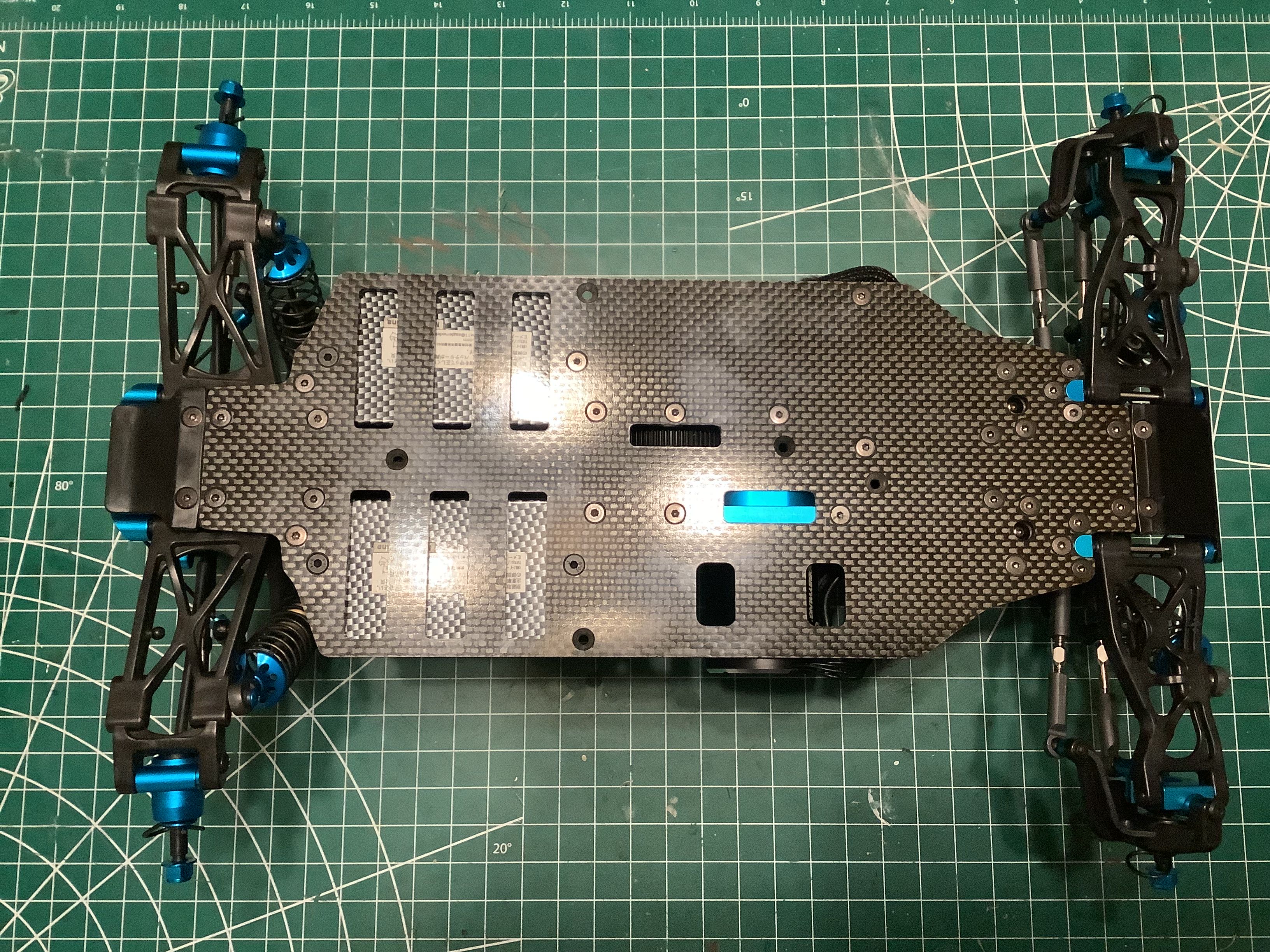
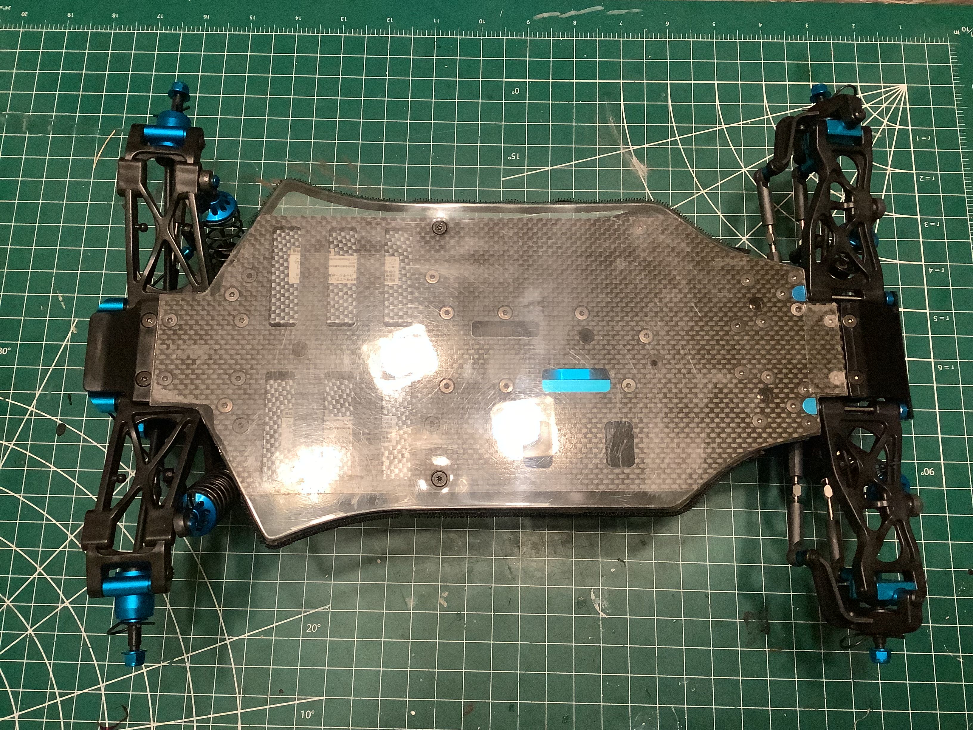
This bottom view shows how nice and smooth it is with all the
countersunk screws recessed into the surface. Even so, the
addition of the under tray shown on the right serves to protect
everything (especially the carbon chassis plate) and keep debris
out. I left my tray clear so I can see the chassis.
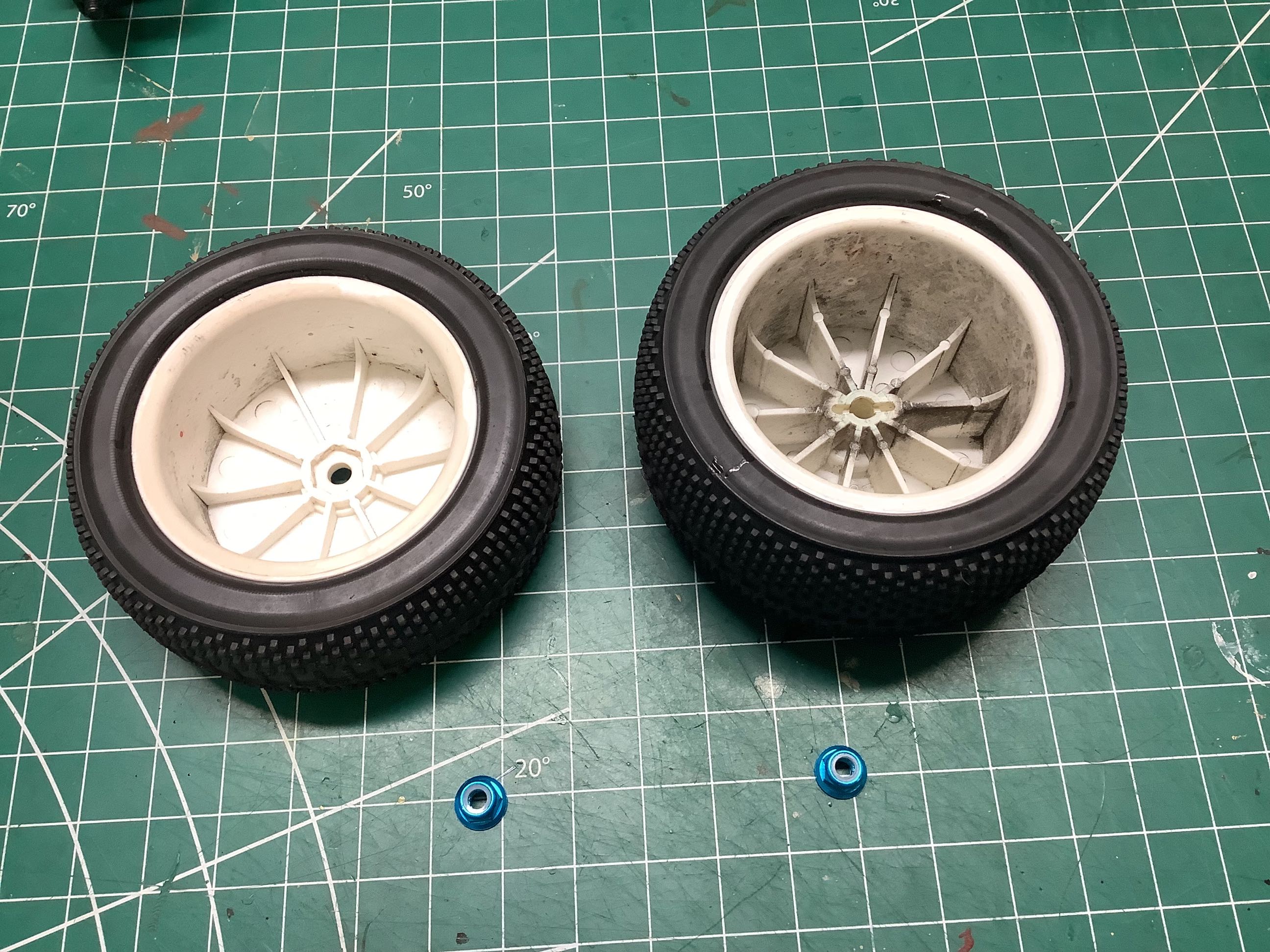
The rear wheels do not use hexes, they attach directly to the drive pins
which means unique wheels are needed. The narrower front wheels are
more standard. I used a set of Tamiya dual block tires in competition
compound for this buggy.
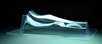
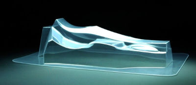
The TRF 501X uses a very low profile body which has almost no extra
clearance beneath it. All electronics and wires must be very
carefully installed. Despite looking the same, the 501X and World
Edition bodies are actually very slightly different. They are
compared in the photos above. The difference appears to be some
extra room in the WE body in the "hump" which sits over the motor and
electronics. The official Tamiya statement claims this is for
"improved aerodynamics", but it looks to me like it is just providing
more room for electronics.
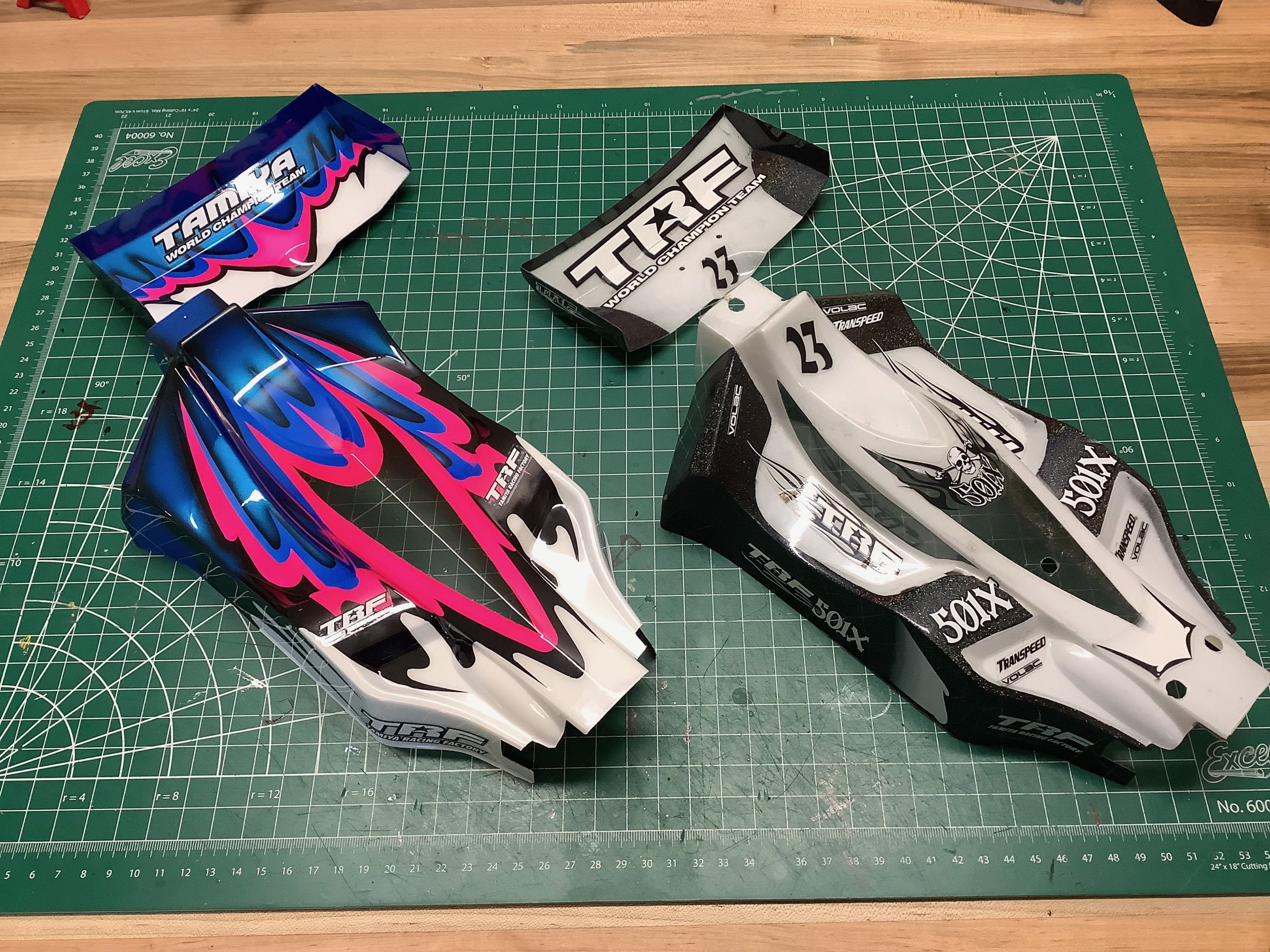
This picture compares the two bodies I ended up with. The body
on the right came with the model and uses a very nice black and white
livery with a Lame spray effect giving it a sparkle. Despite the
fact that this was a very nice body, I just had to have the classic TRF
livery so I took the extra clear body that also came with the model and
sent it off to a professional painter. The result is on the
left. I decided to remove the body posts to avoid punching holes
in the body since this body also attaches with Velcro anyway. I
didn't have a 501X sticker sheet so I had to use some more
generic TRF stickers. A close look will reveal that both of these
bodies are the original 501X type, not the modified version from the
World Edition.
©2022 Eric Albrecht