Cross RC BC8 Project
Page 2: Building the Chassis
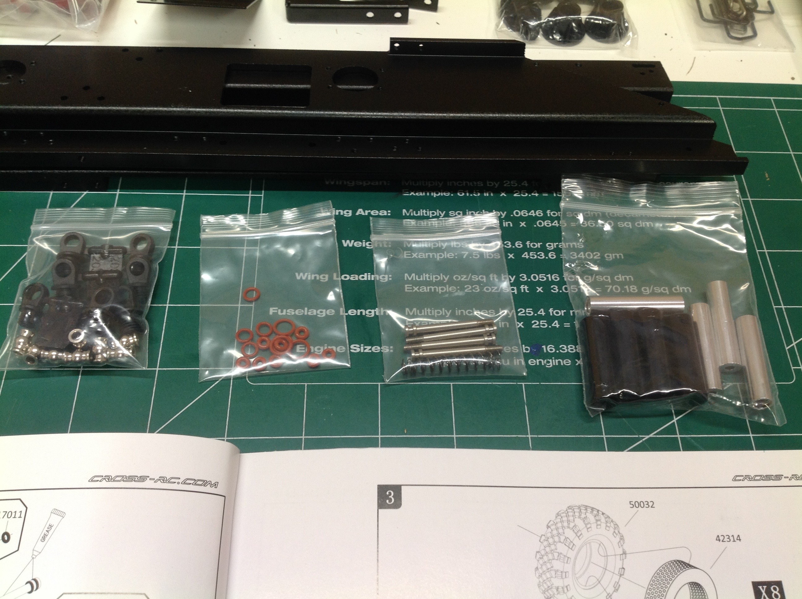
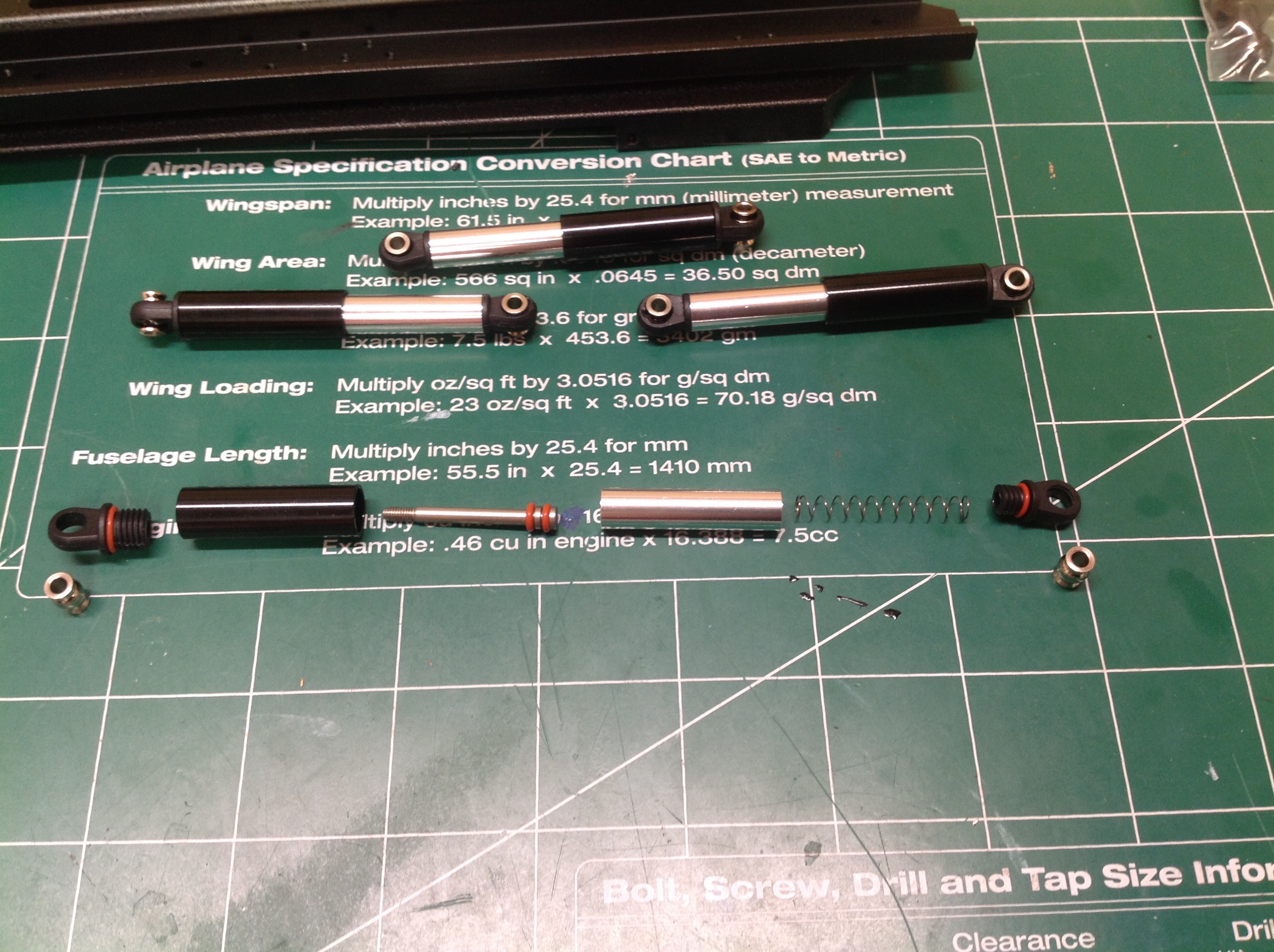
The build starts with the shock absorbers. At first glance these
might appear traditional but they are really just for looks and offer no
significant damping. There is no oil in these dampers, just a
small spring to help them extend, but too small to actually provide any
support to the vehicle. The cylinder and rod are aluminum.
The internal steel rod is actually attached to the head end, not the
rod, so it does not move with the rod. Shocks are only used on the front
suspension.
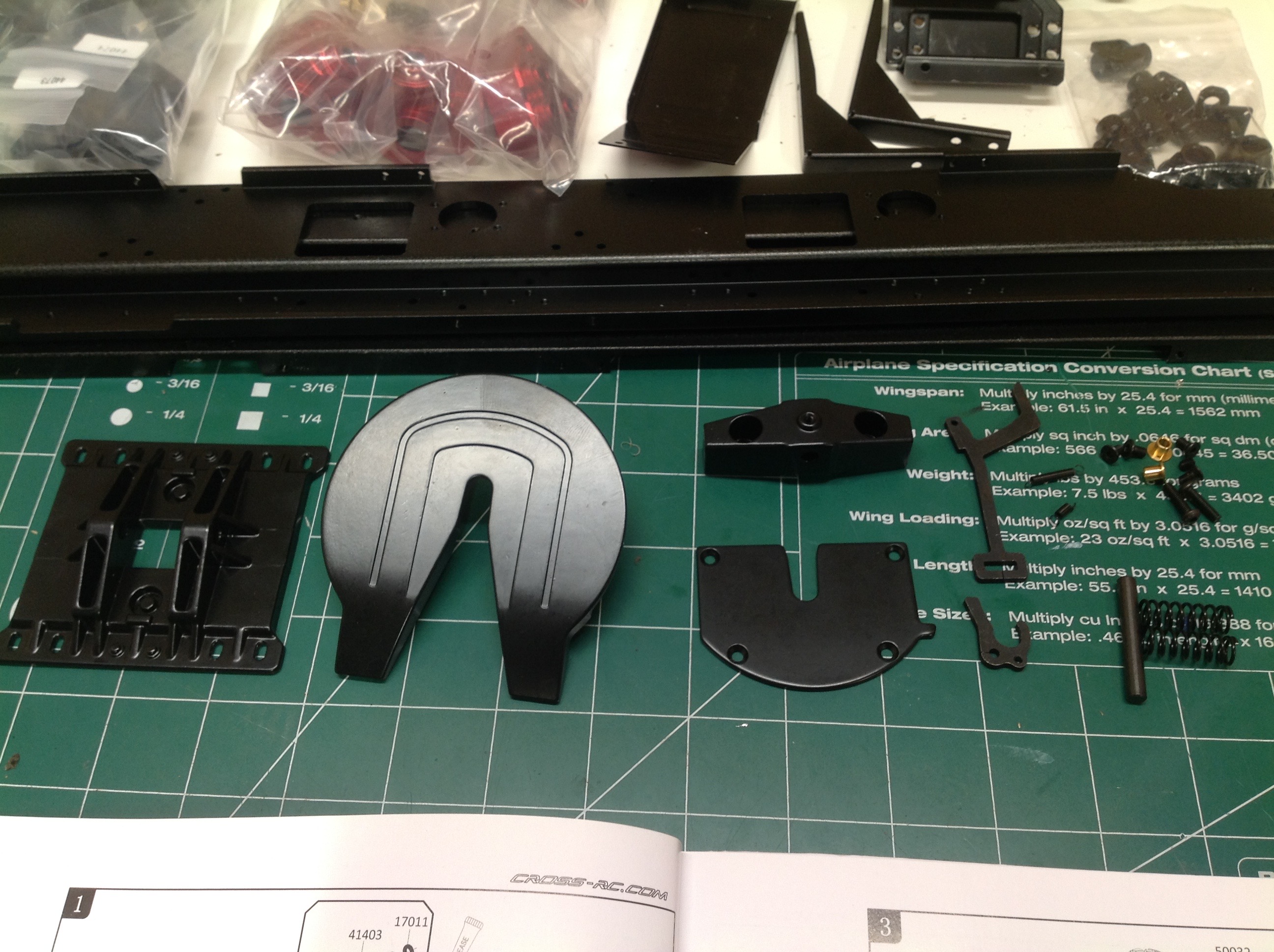
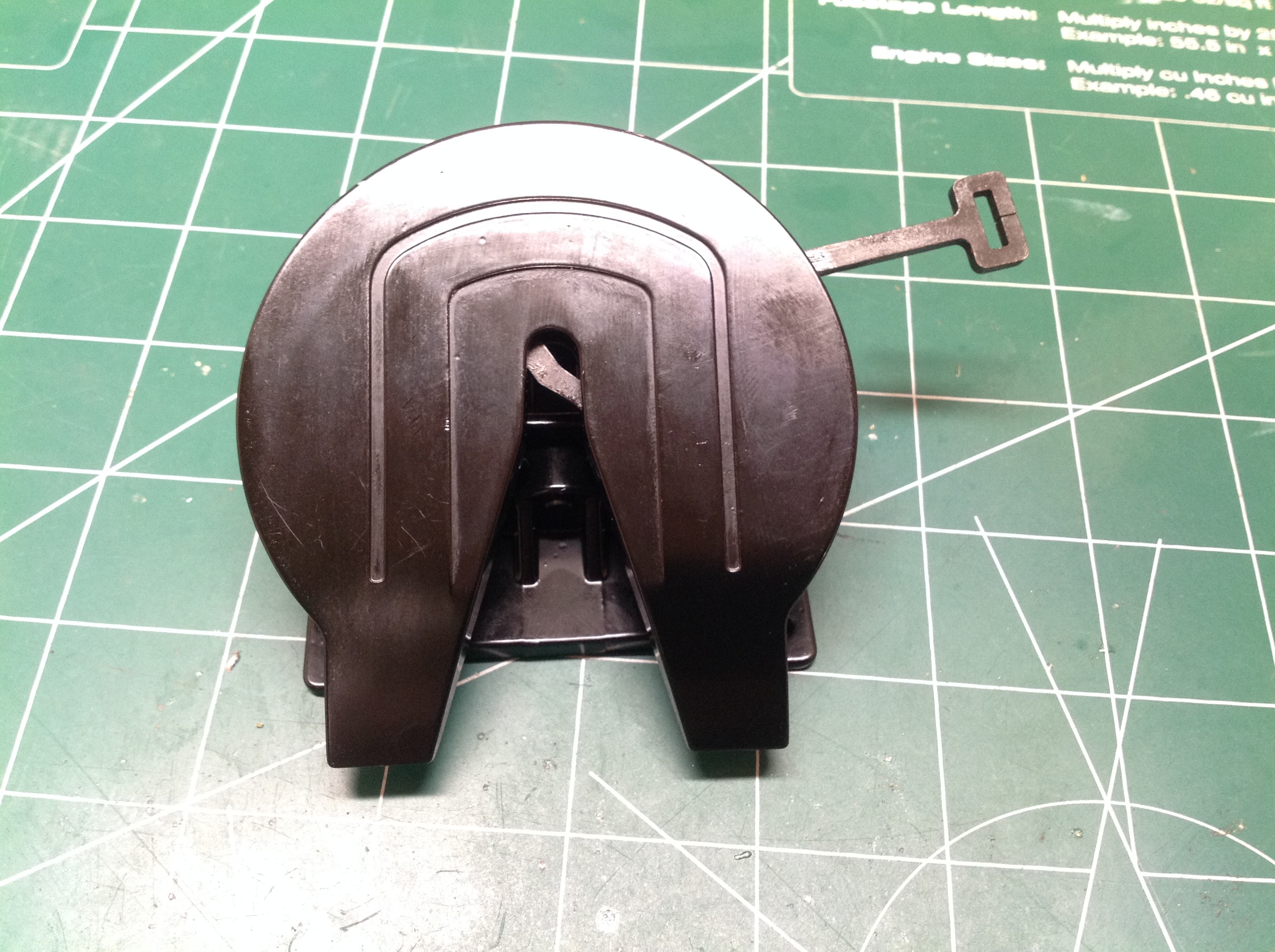
The next thing to build is the fifth wheel coupler. Everything you
see here is metal, some of it steel. From beneath you can see the
coupling mechanism. This is designed to engage and lock when a
kingpin is pushed into the coupler. The tab you see sticking out
on the left needs to slide and did not work at all at first. I had
to do quite a bit of filing (you can see the files) to provide enough
clearance to allow the parts to work. A bit of grease helps as
well and will slow the formation of rust in the mechanism.
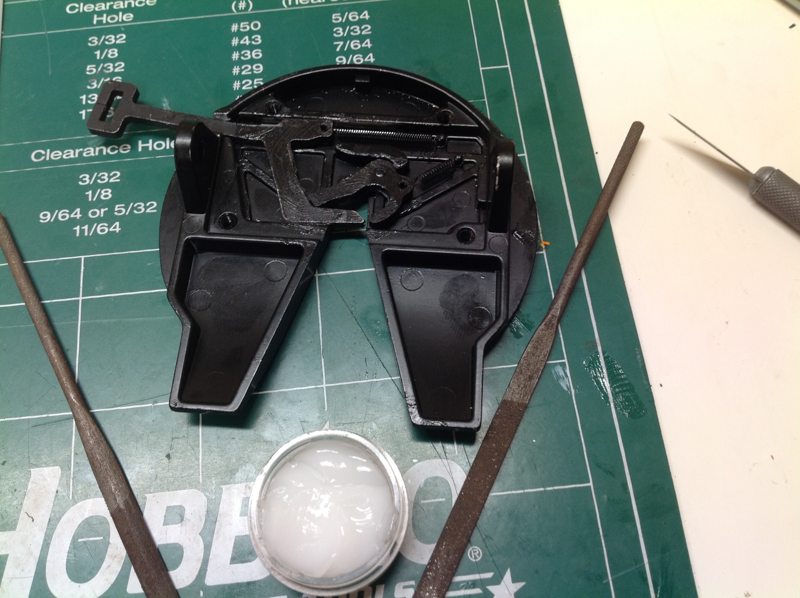
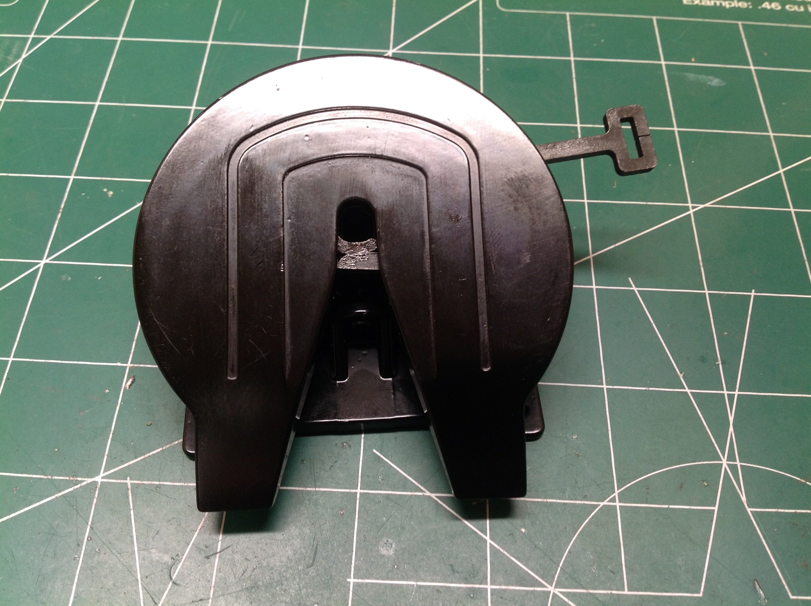
These pictures show the two states of the coupler. On the left,
the tab has been pulled out to put the mechanism in the unlocked
position. The finger you see inside the coupler is the "trigger"
against which the kingpin pushes to engage the lock. On the right,
you can see the coupler locked. The mechanism is over center so
it will stay locked no matter how much load you put on the
kingpin. This whole system is very heavy and strong and obviously
designed for a huge trailer.
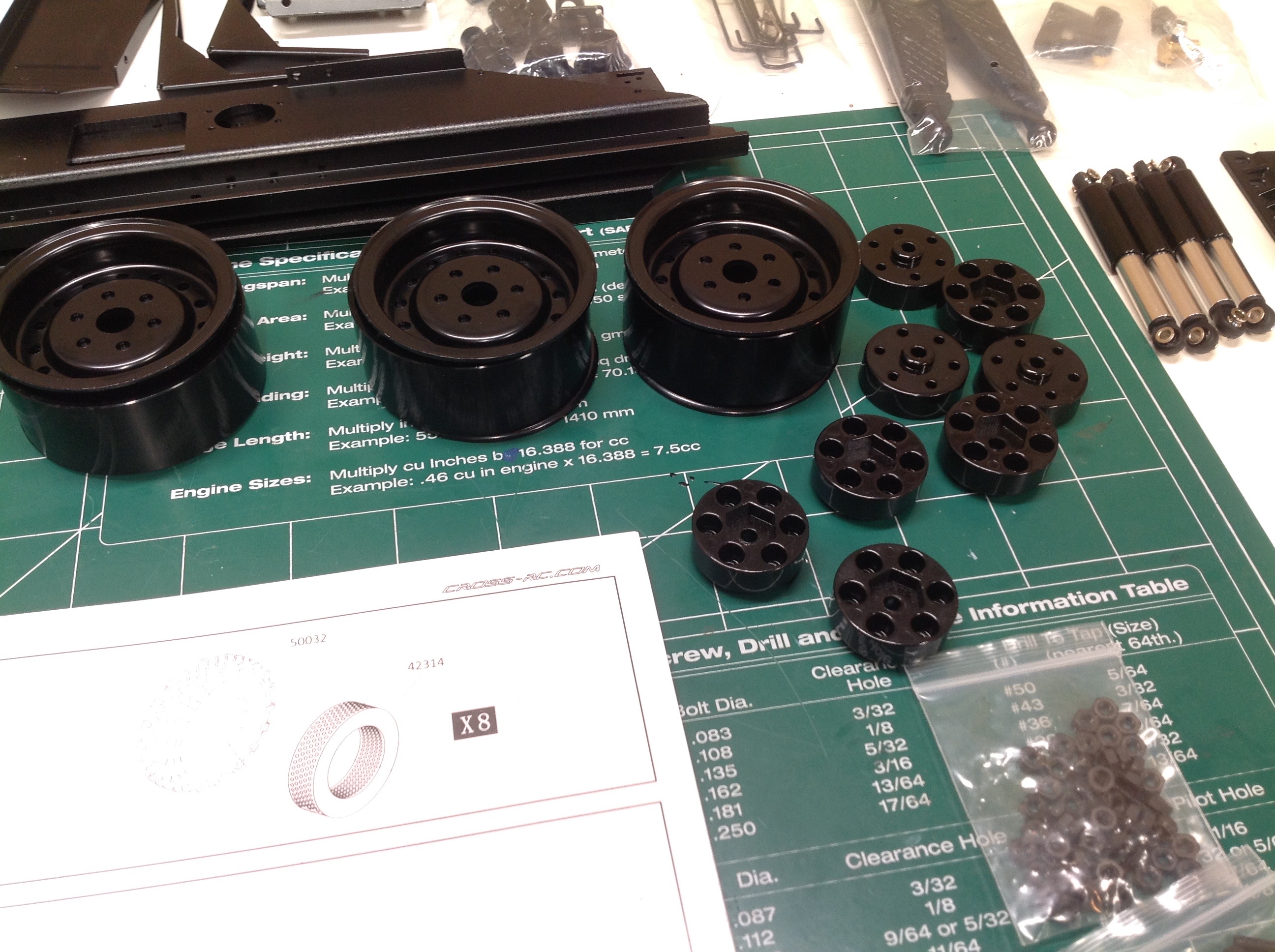
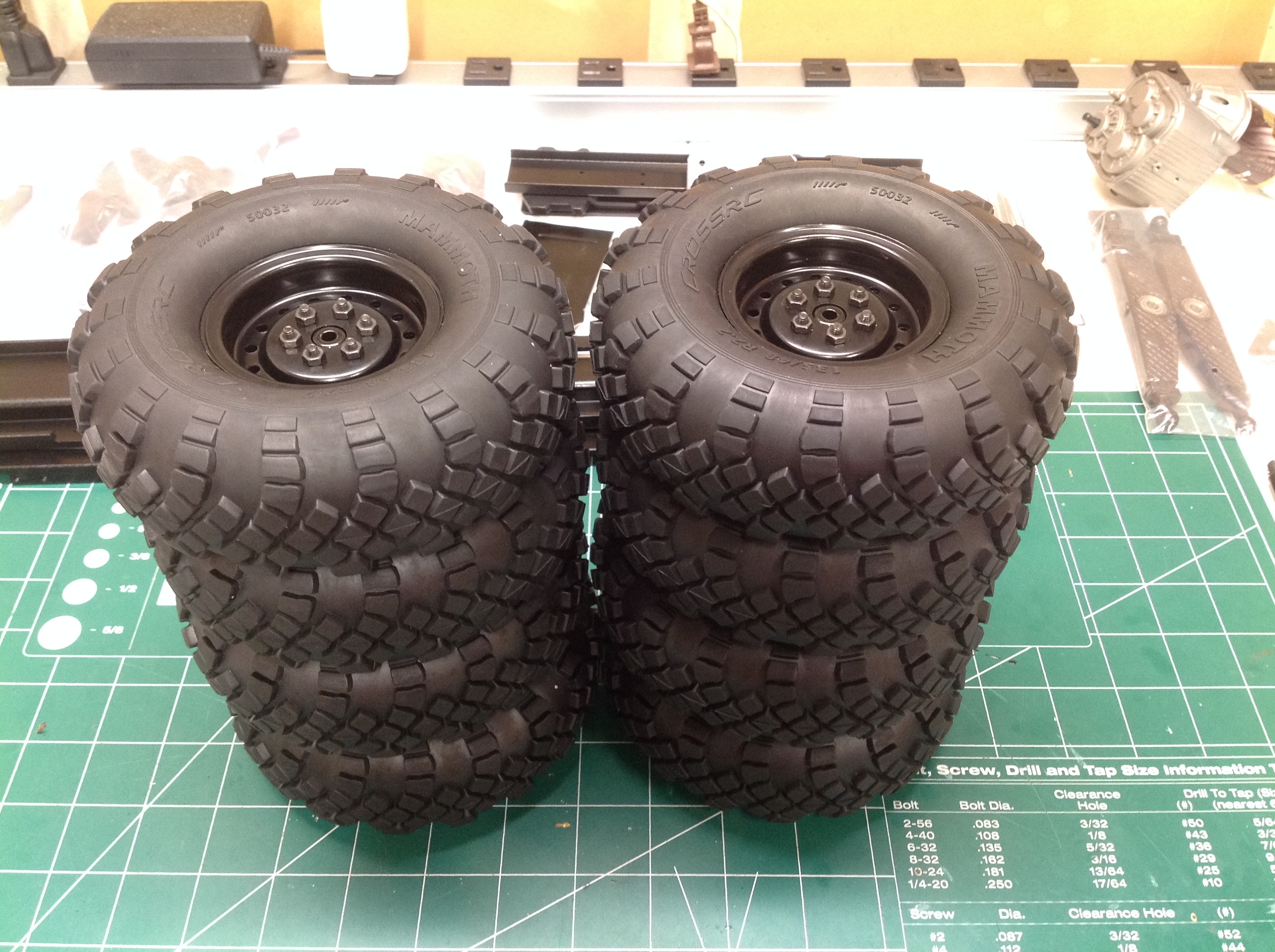
With 8 steel beadlock wheels to build, each with 4 parts and 6 screws,
you can expect some sore hands. Each is built by first installing
two longer screws to get the outer rings cinched up, then installing
four shorter screws, and finally removing the original long screws and
replacing with short. Once everything is tightened you get the
pile on the right. The tires are directional so you need to make
sure to built four of each or you will be cursing when you have to
rework them.
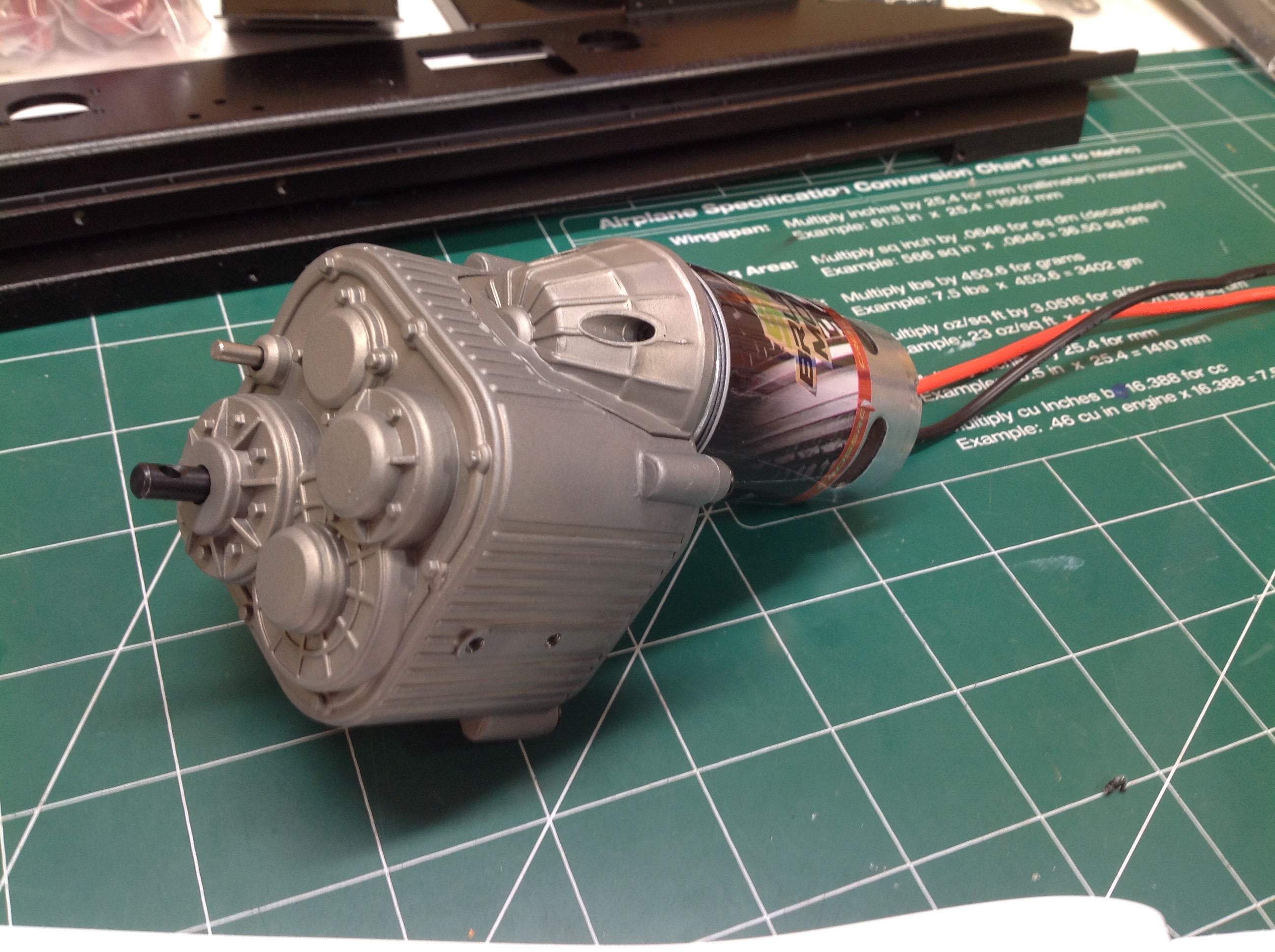
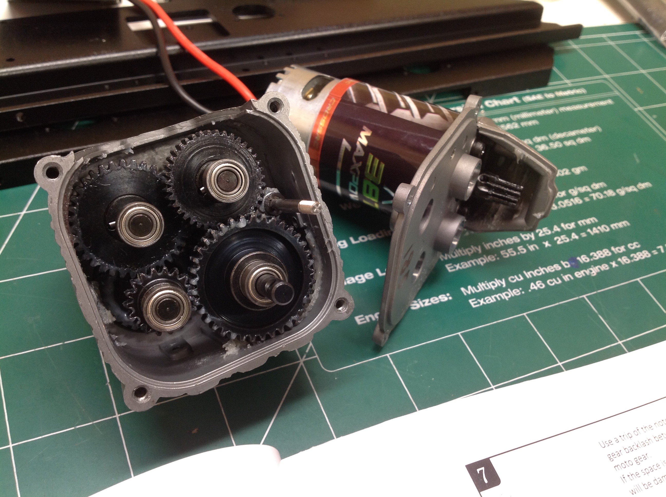
The 2-speed transmission comes pre-built, but obviously I couldn't just
leave it that way. I opened up the case to see how it worked and
check for proper lubrication. Inside I found the four gears shown
offering massive reduction. The tiny pinion can be seen on the
motor on the upper right. The lower right gear contains the shift
fork. All the gears are steel and all are supported by ball
bearings.
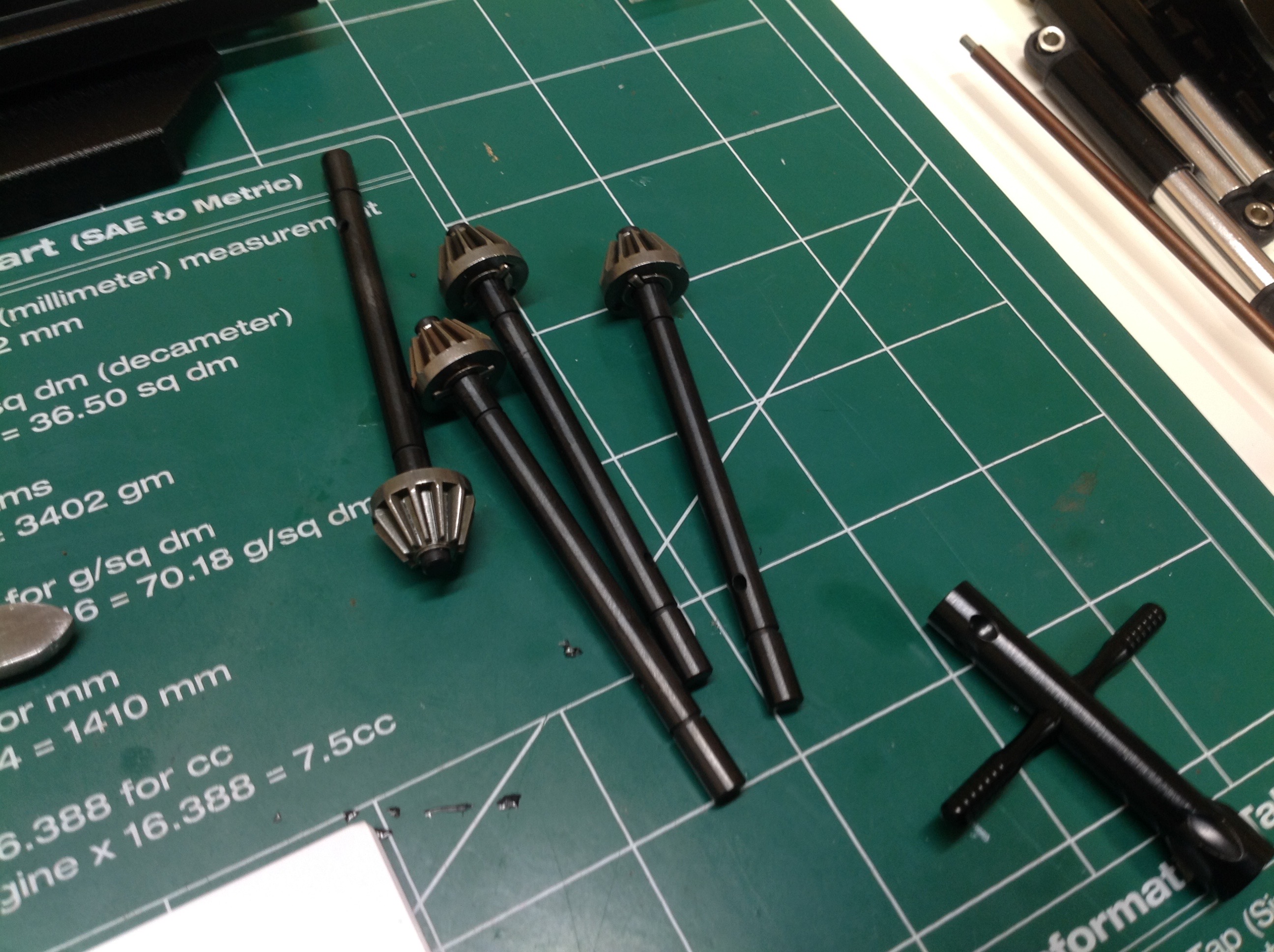
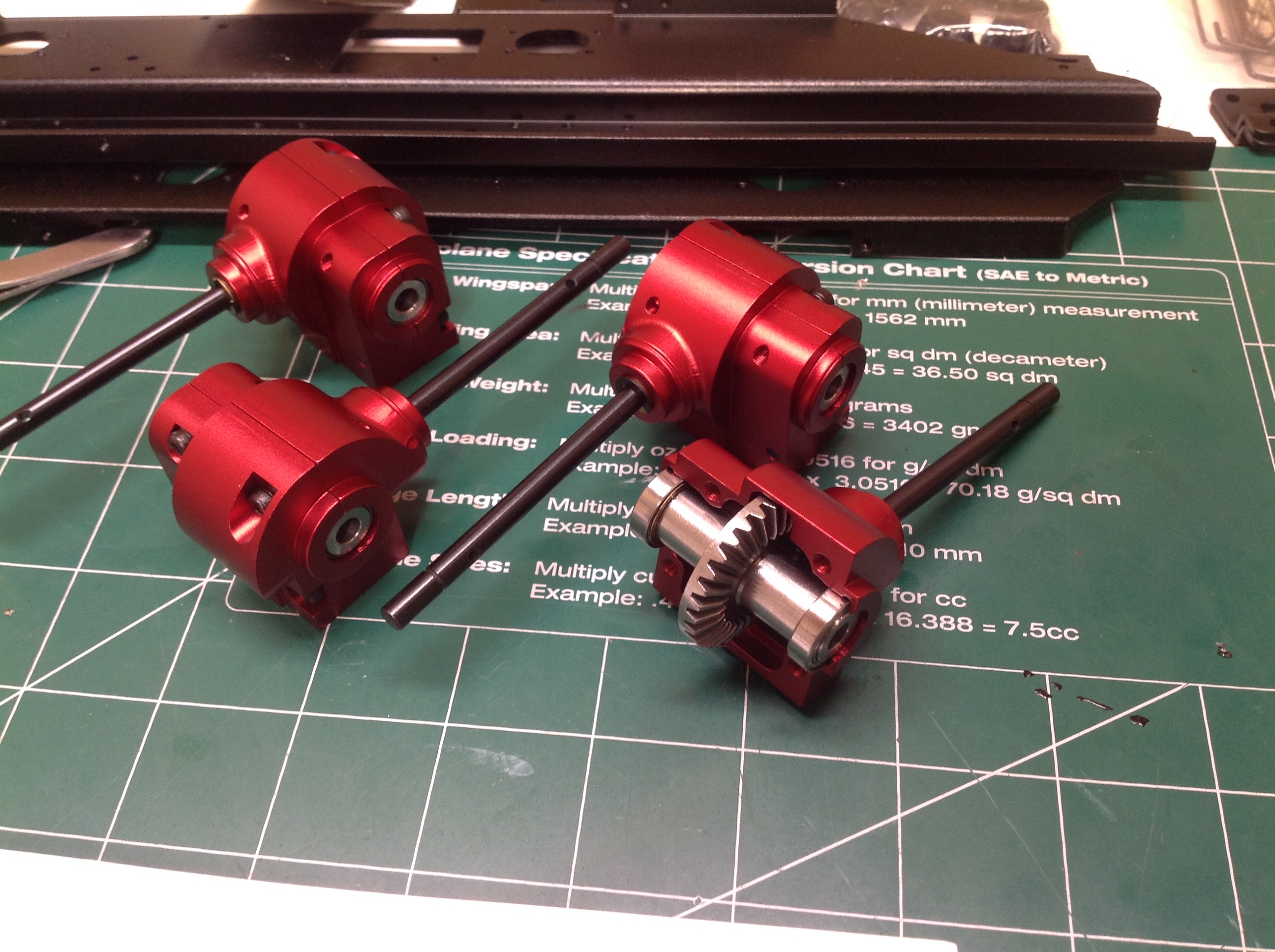
Time to start building the transfer cases and differential
gearboxes. The main gearbox has a forward and rear output.
We need to split each of those into two and then send the output of each
of the four to an axle. This picture shows the pinion gears which
go in the diff housings.
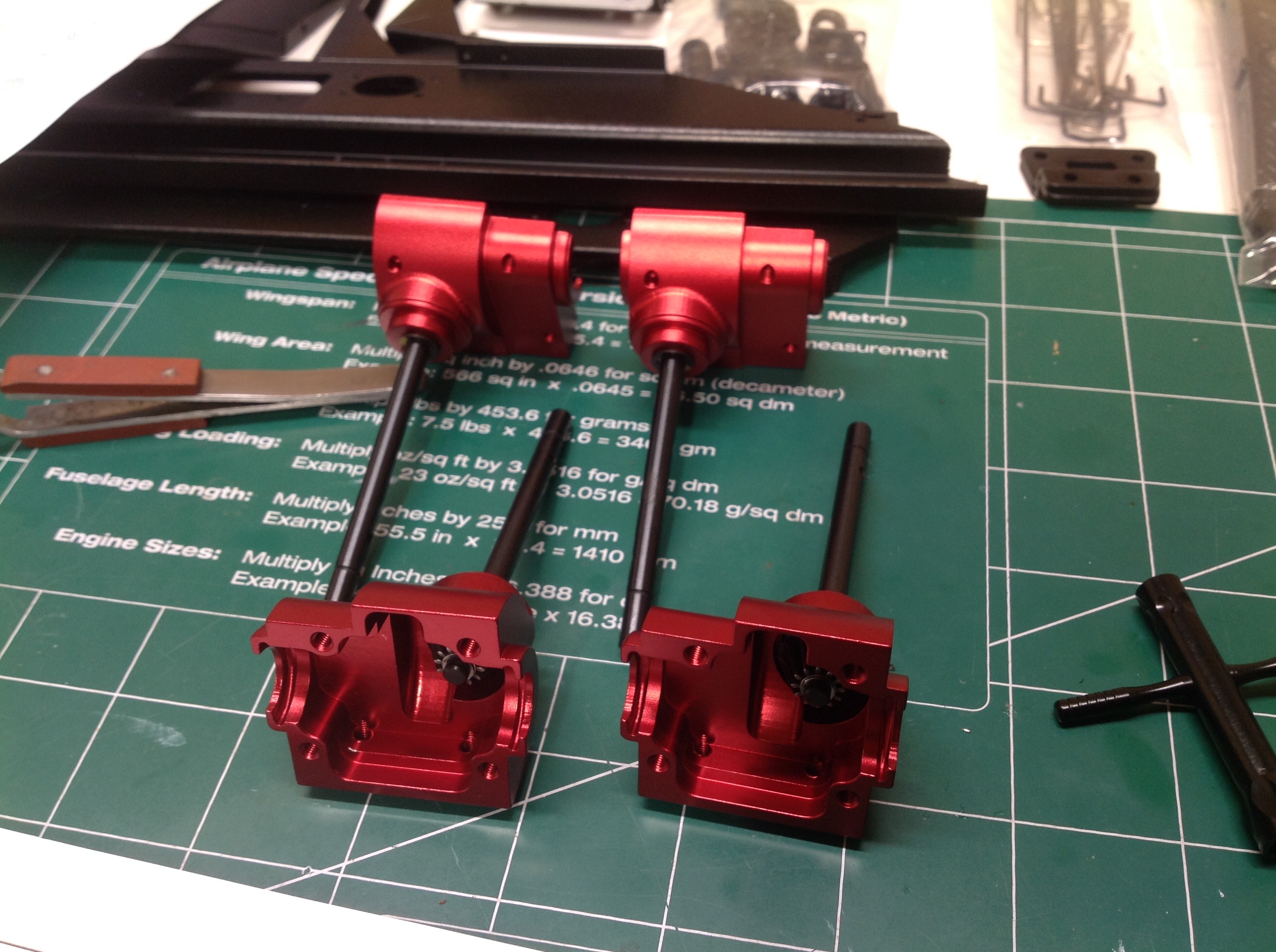
The flagship version of the kit has red
anodized housings which each get a pinion gear. Each
of the four differential housings now gets a locked spool as
shown.
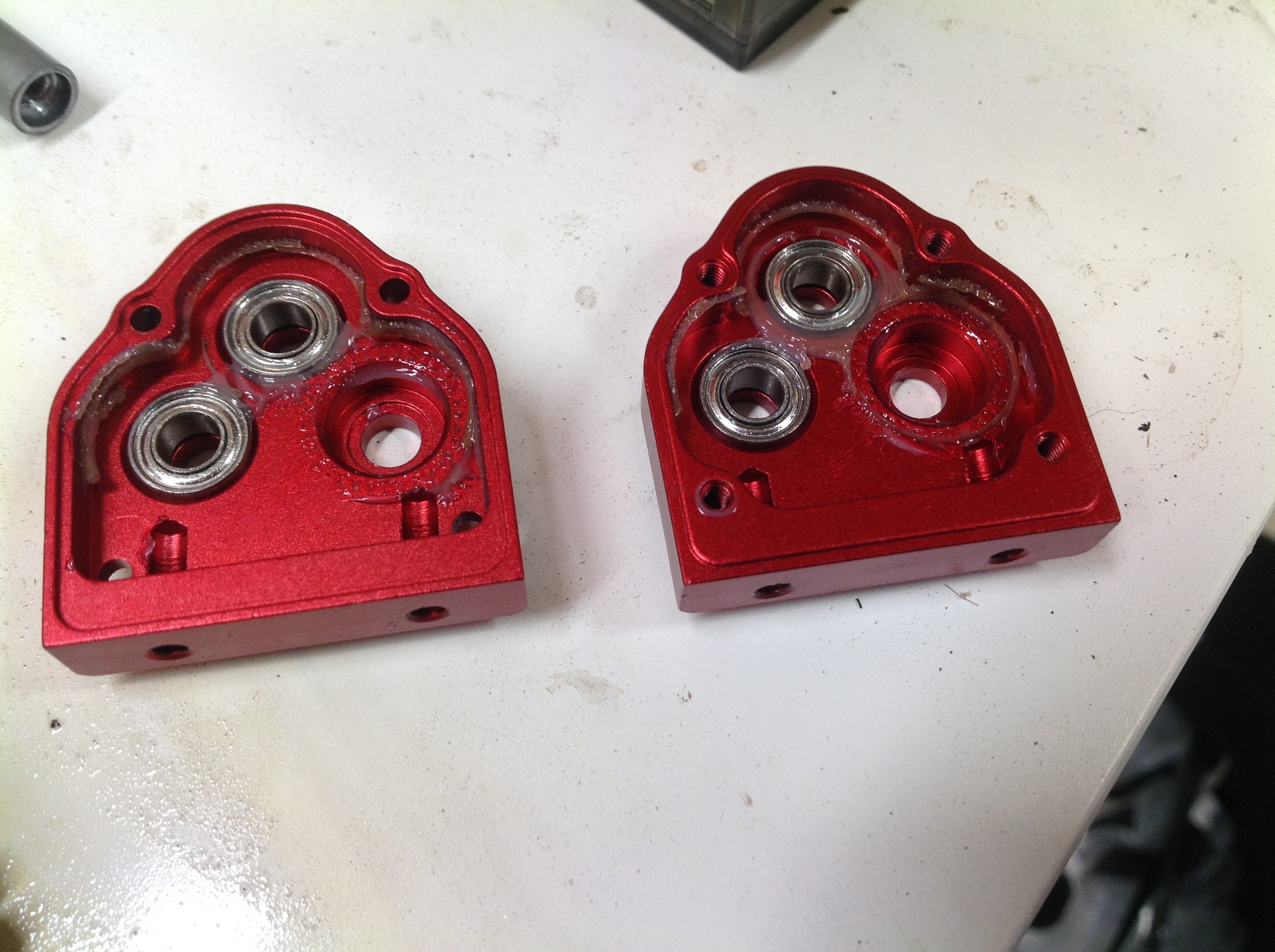
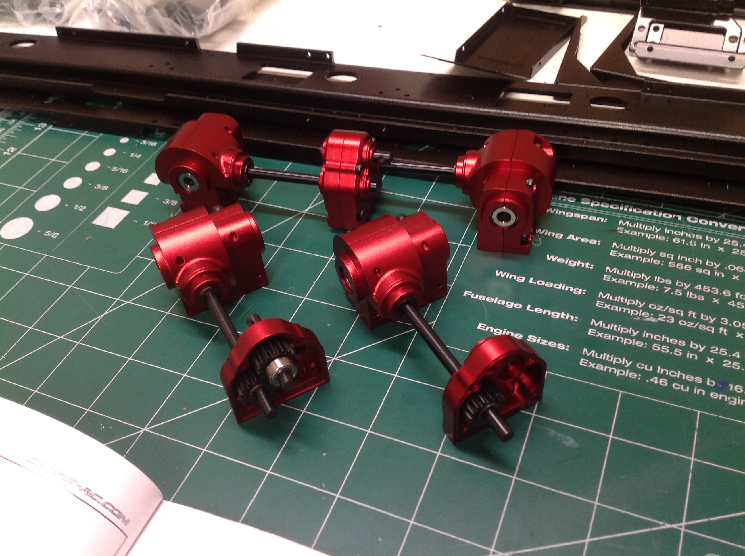
After that each pair of differential housings is joined at a
central transfer case. The left hand image shows the internals of
a transfer case. The outputs are side by side and the input is on
the top. It is interesting to note that one end of each shaft has
no bearing. This was a last minute addendum to the
instructions. The gears inside the transfer case are all the same
size so the ratio is 1:1. The right hand image shows one completed
assembly and one ready to button up.
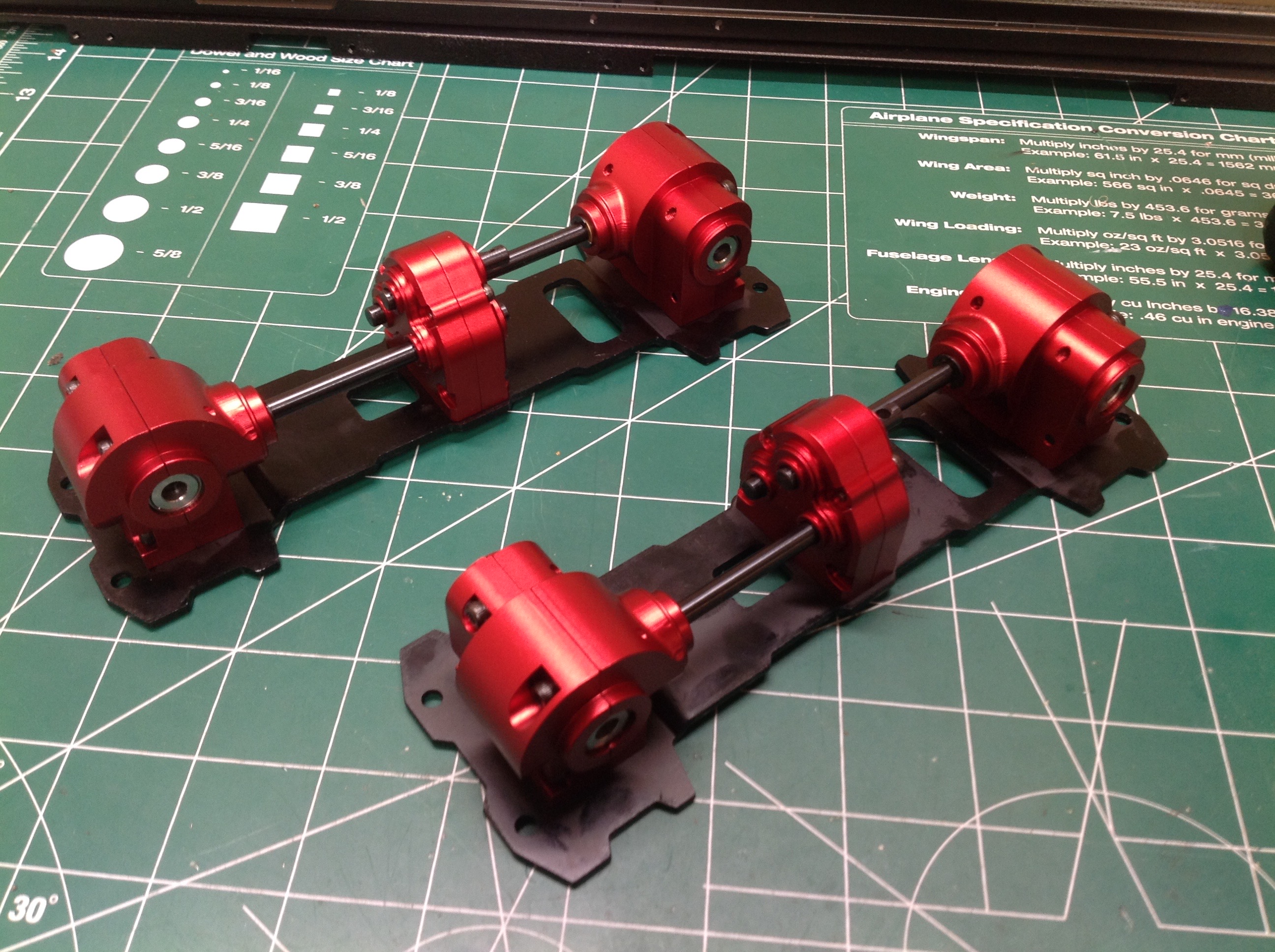
Here are the completed gearbox assemblies attached to their base
plates. There were a couple of issues here. The first issue
is that I did not notice that the base plates are not symmetric.
There is a slot at one end that is needed to access steering adjustments
later. Naturally I put both of them at the wrong end. The
other issue I had was enormous drag in the system. The spacing of
the holes on the plates is such that the housings are pulled apart too
far which preloads the bearings. I went back through and removed
many of the shims to add more space. This completely fixed the
problem.
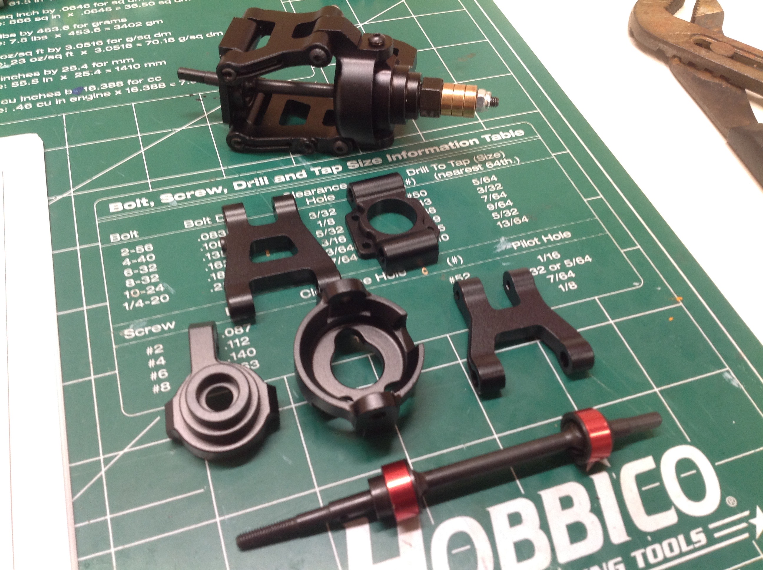
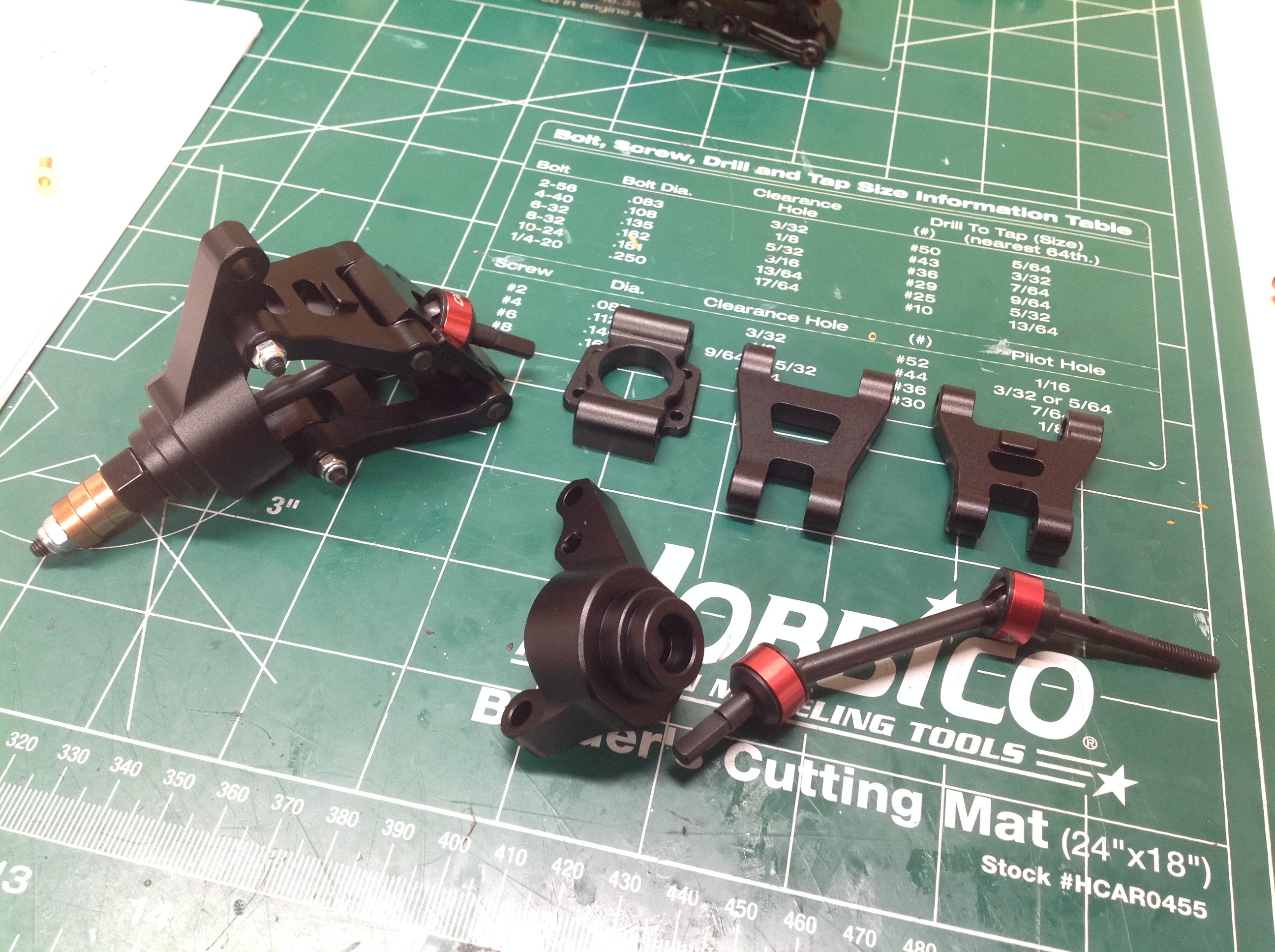
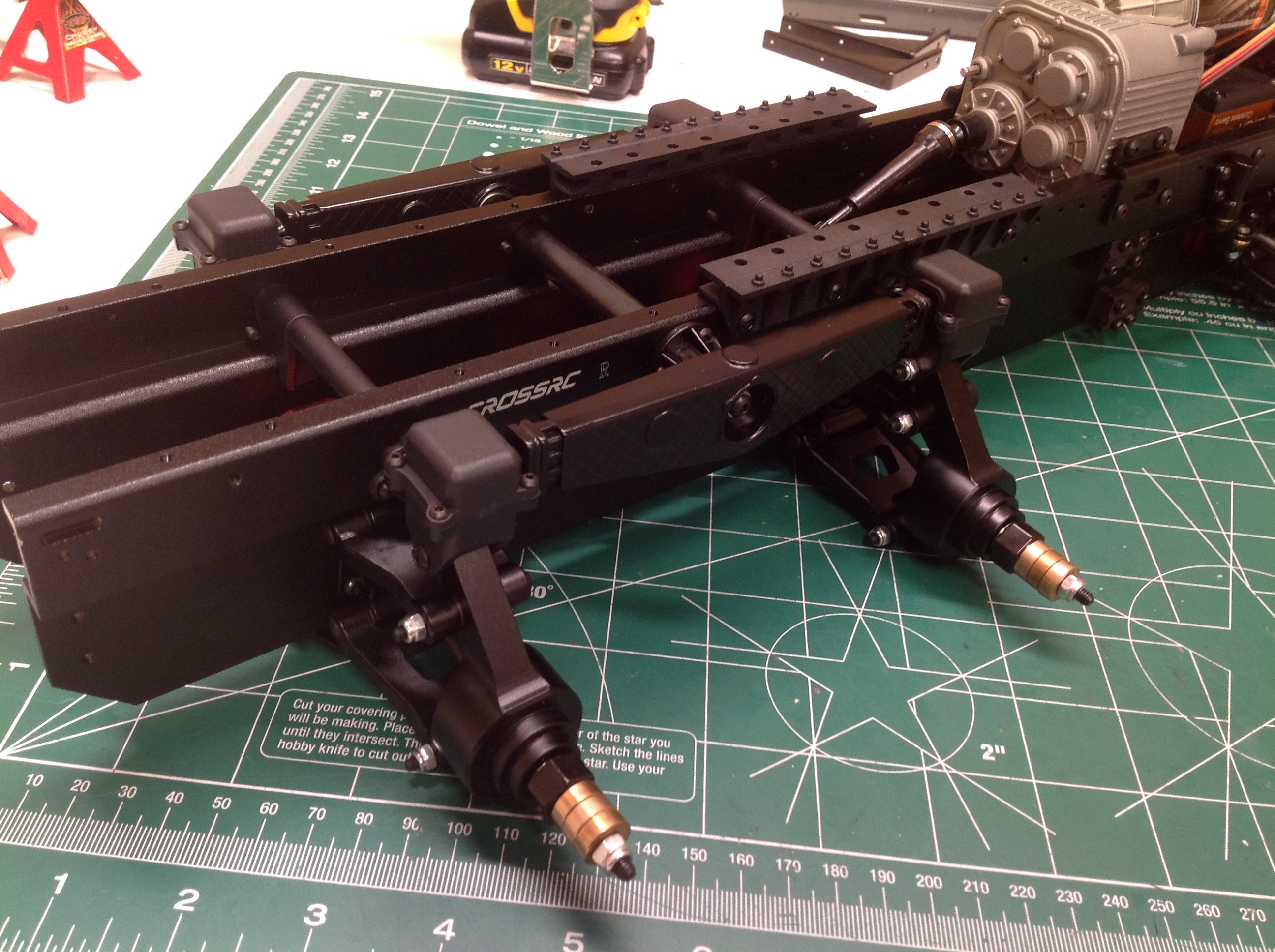
Now we'll start on the 8 wheel double wishbone independent suspension
(you don't get to say that very often). All of the components here
are metal in the flagship version of the kit. The front two axles
are steered. Each outdrive is a CVD type. 1st and 2nd axle
use the same assemblies and left/right are mirrored. Upper and
lower arms are not the same length which means that camber will change
with suspension travel to a certain extent. The bronze bushings
you see here are just spacers that I installed to hold the drive hexes
on until later.
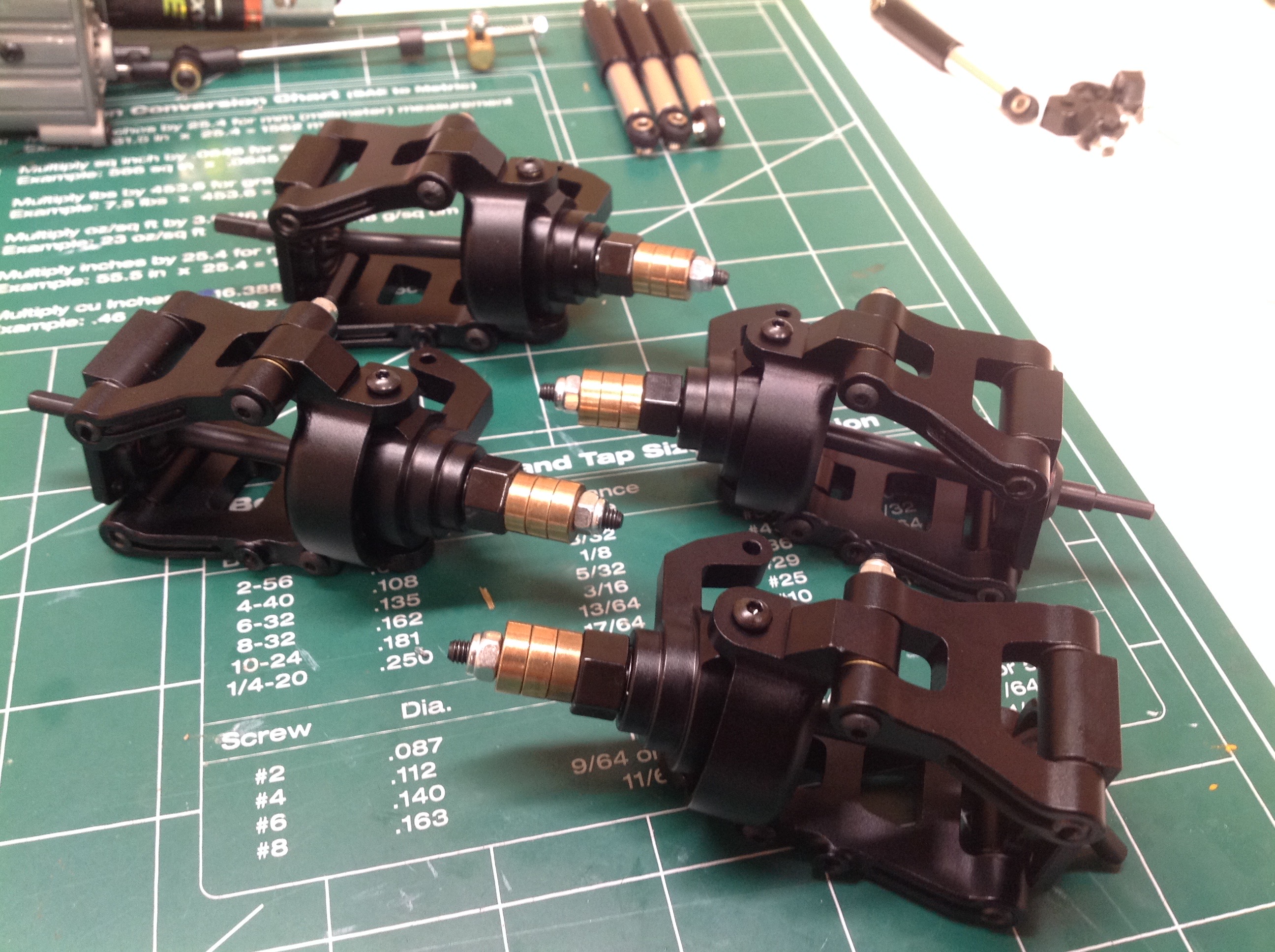
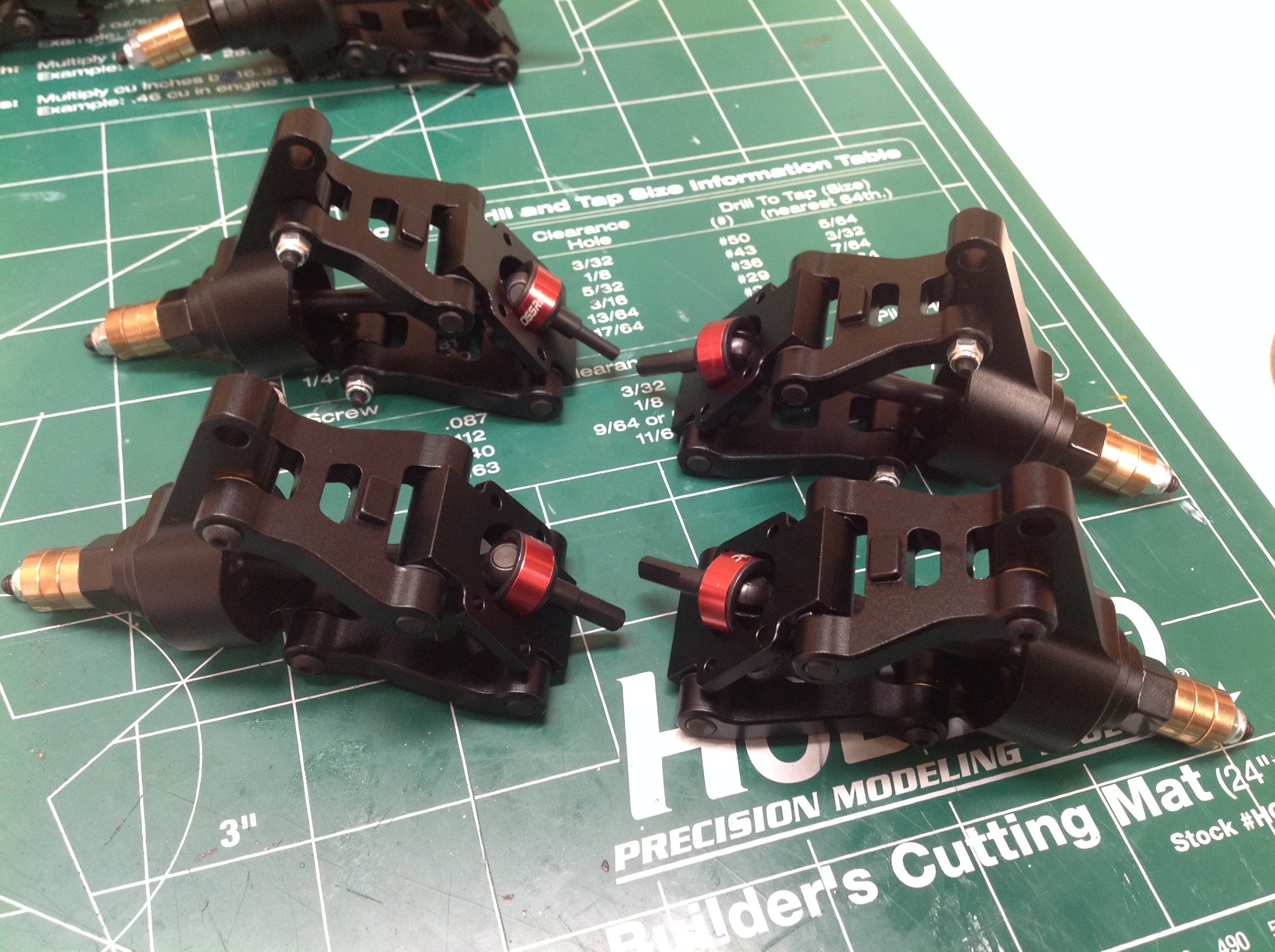
The rear axles are very similar to the front but without the steering
knuckles. The weight of the uprights is ridiculous. There is
plenty of unsprung mass in this truck. In fact, the two rear
axles aren't sprung at all.
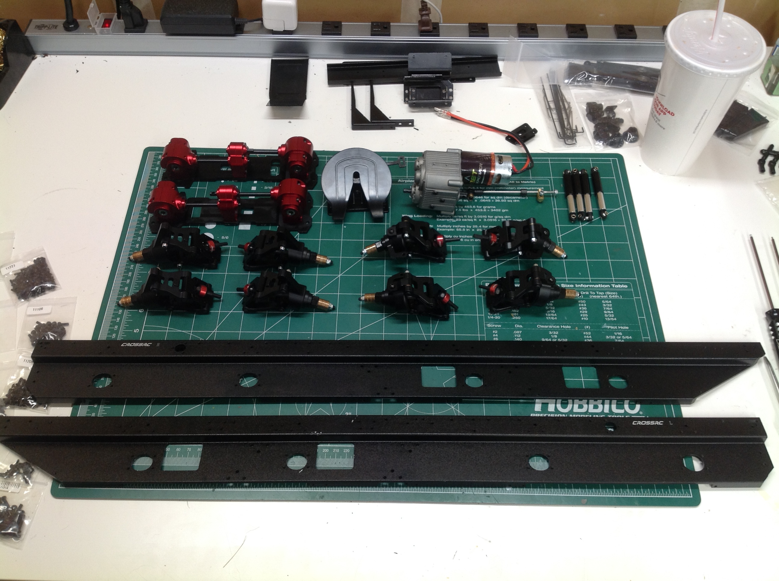
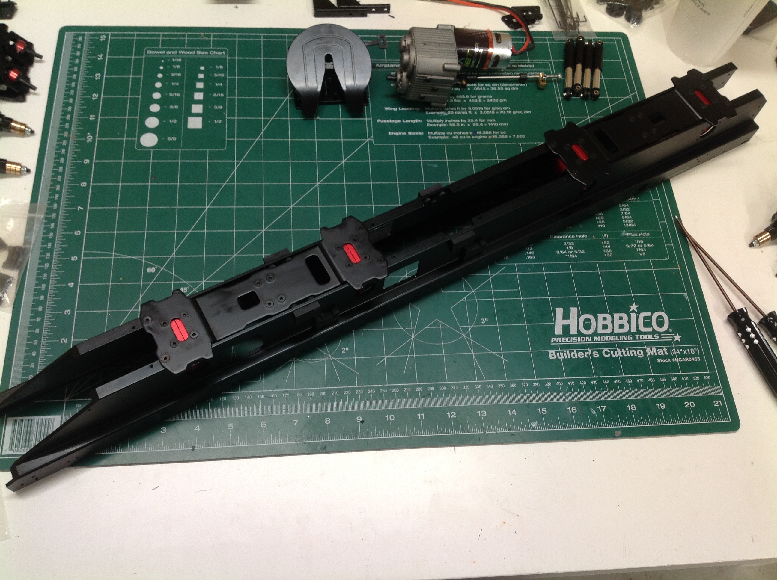
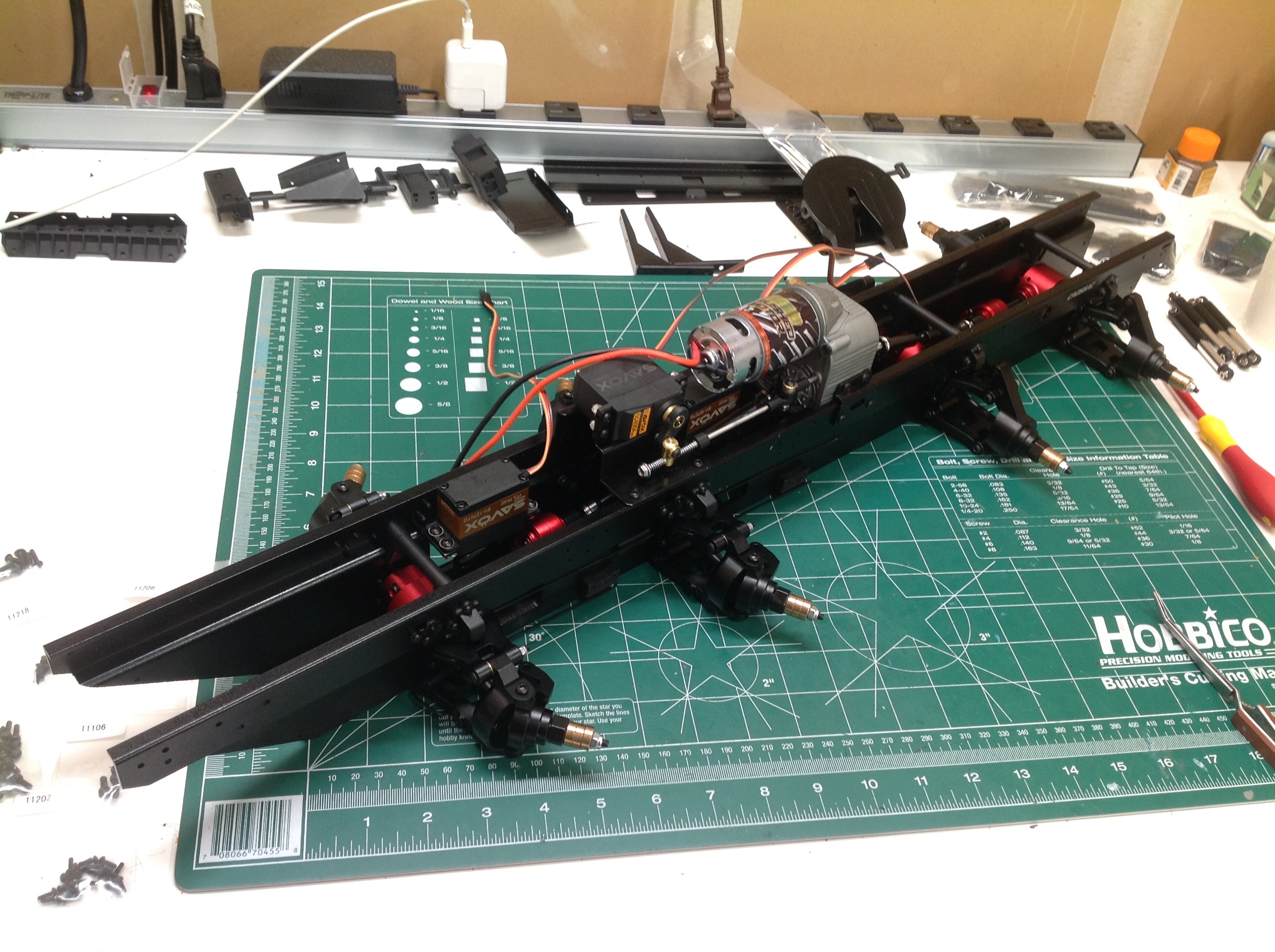
The first image shows all the subassemblies set out and ready for
integration into the chassis. The huge side rails will obviously
form the structural backbone of the chassis. The first assembly
step is to connect the left and right rails together using the transfer
case gearboxes as shown on the right.
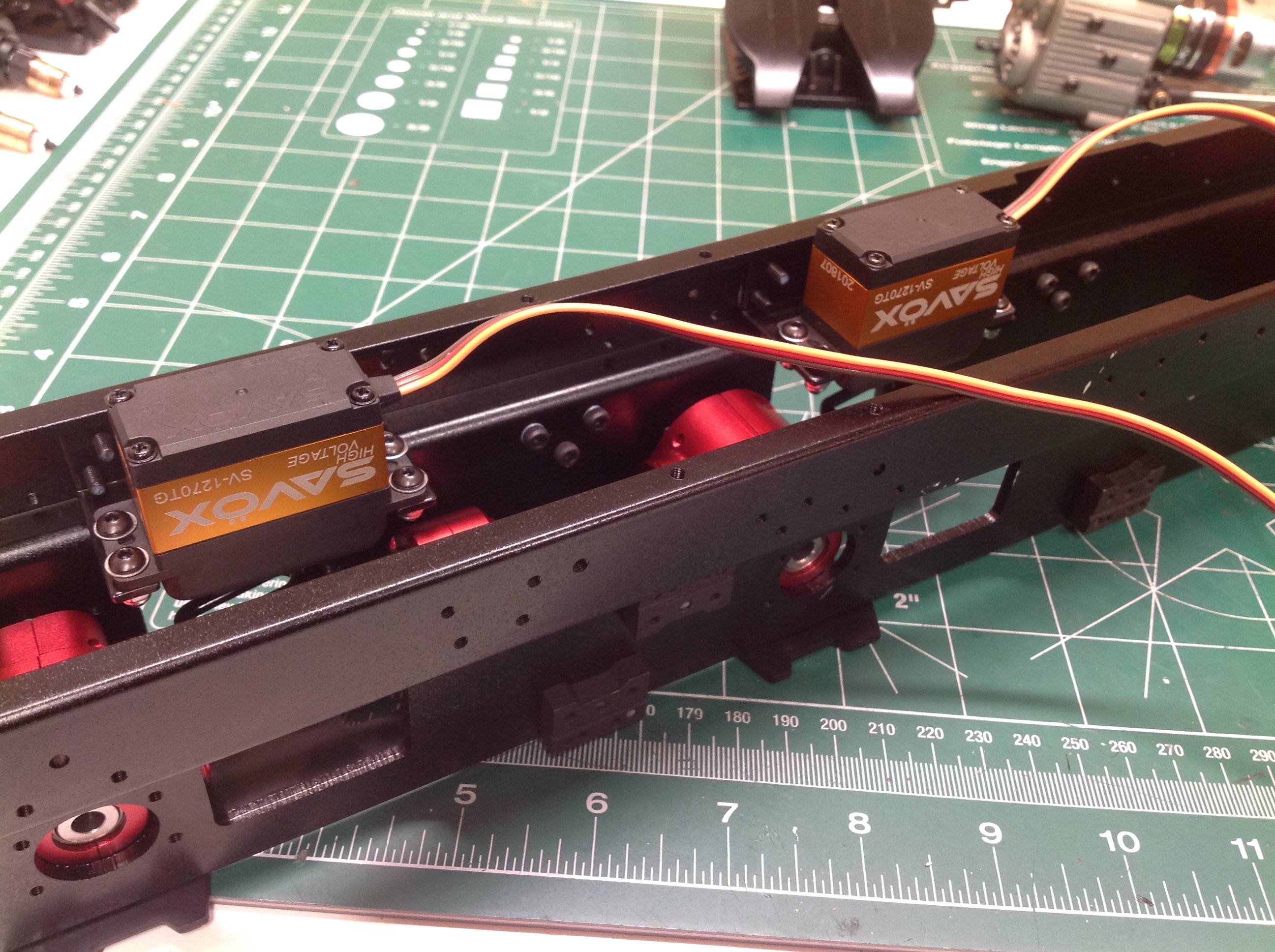
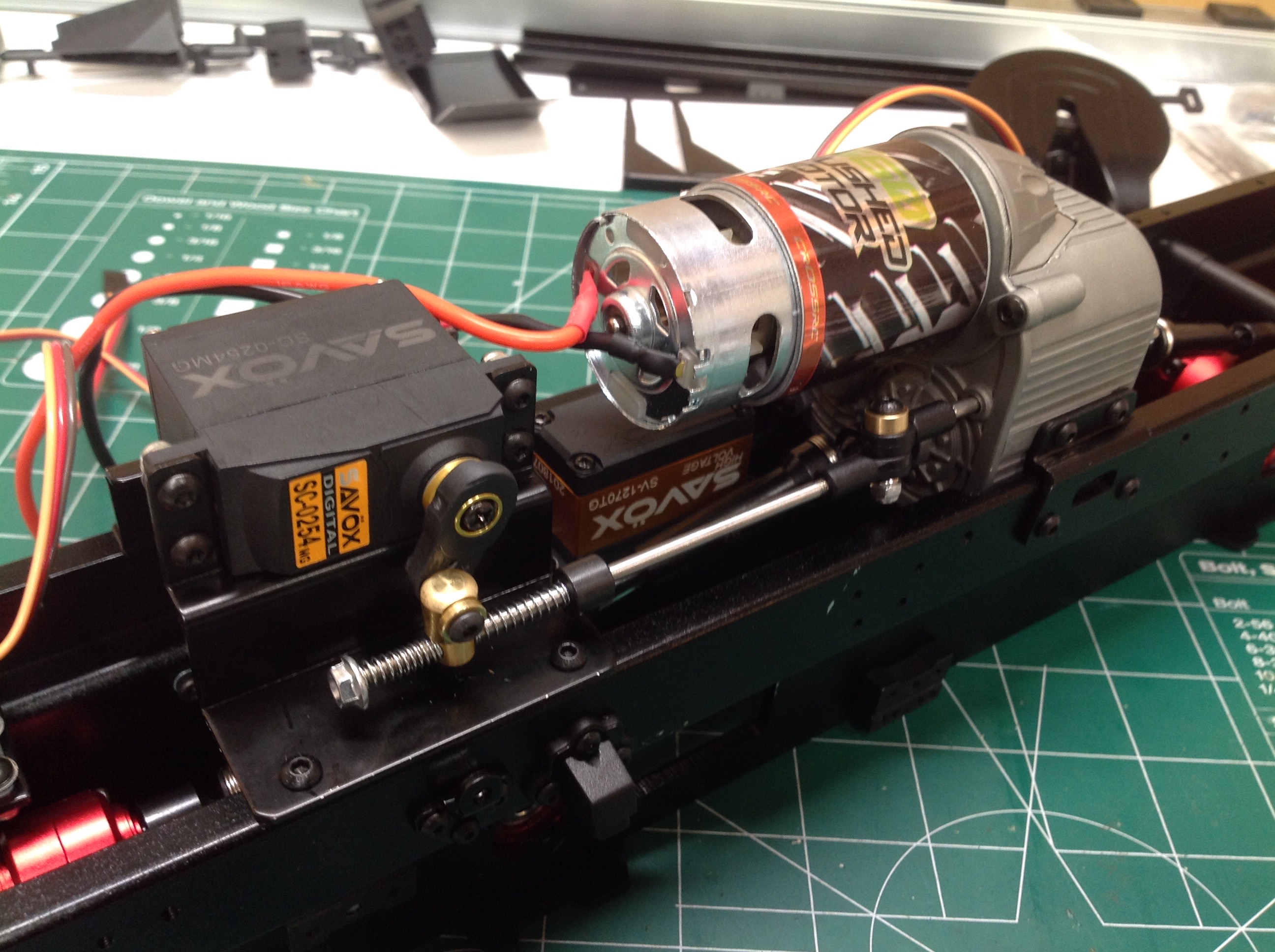
Now we flip the chassis over and install the steering servos. Two
high torque servos are needed in parallel, and Cross recommends at least
30kg-cm servos with high voltage capability if possible. That's
exactly what I did. These monsters will move the four steered
wheels with full weight on them with no problem at all.
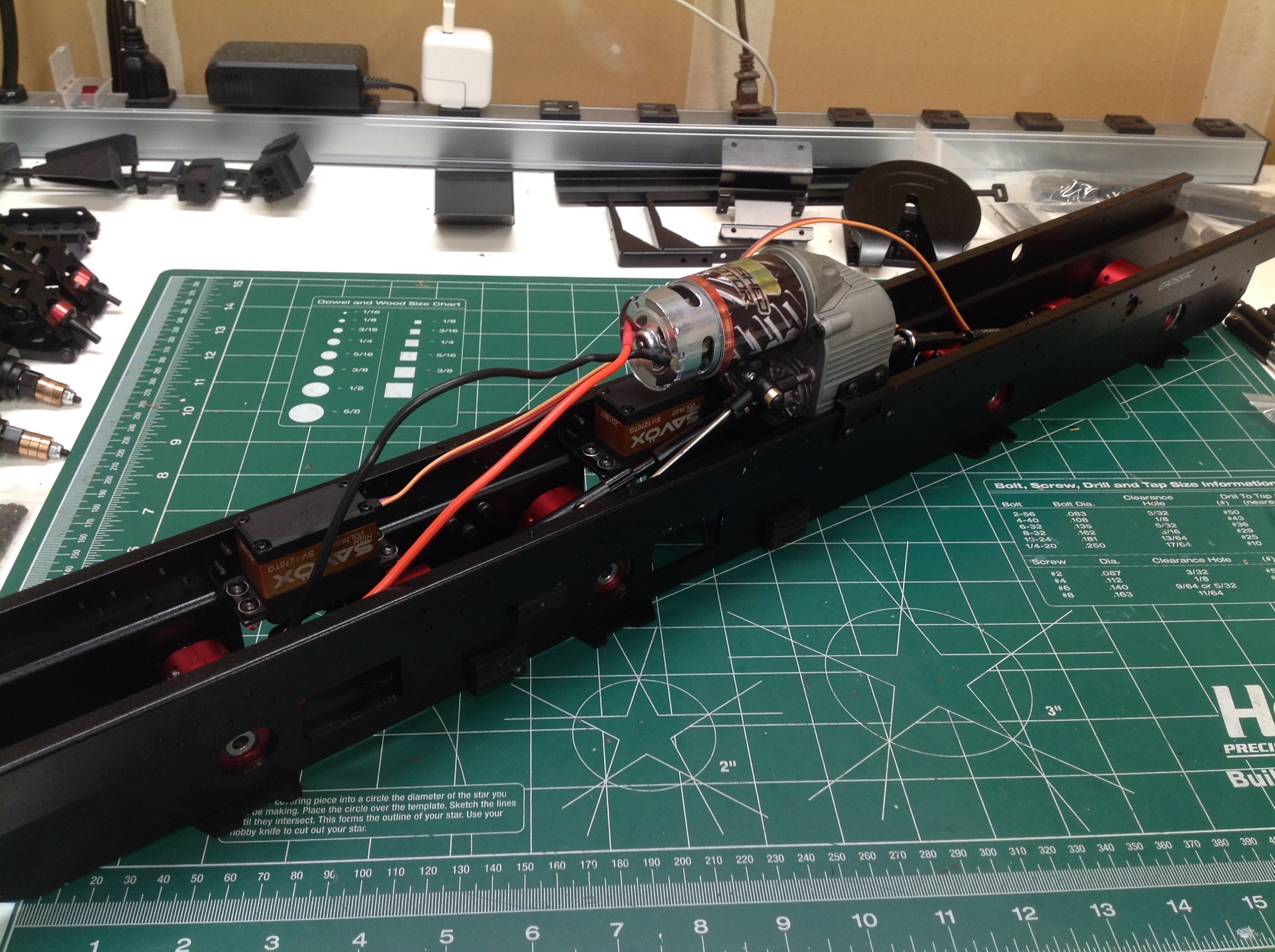
The once the transmission assembly is installed the left and right sides
become very rigidly connected. Looking closely you can see the
steel driveshafts going out to the gearboxes. The we attach a few
other intercostals and the shift servo. Here I could use a much
cheaper servo, but it is still a nice digital unit.
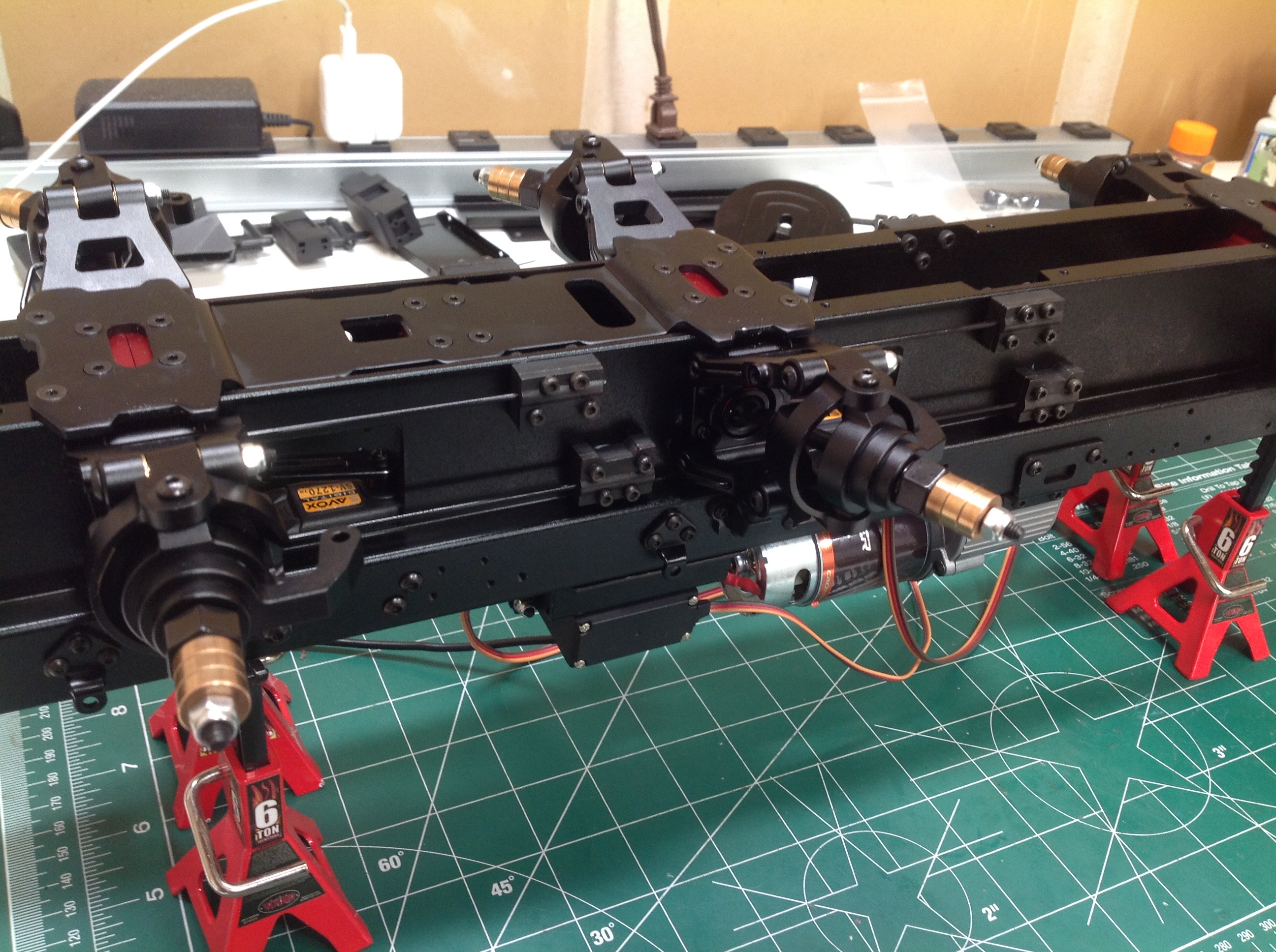
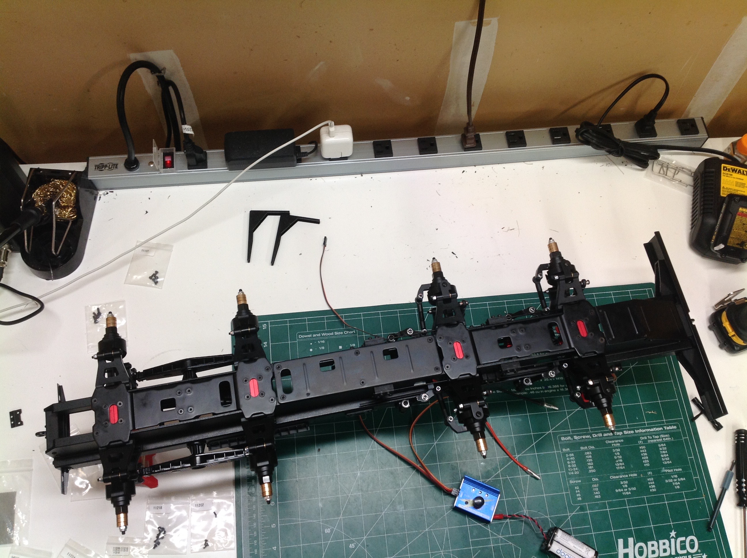
Now all eight suspension assemblies get bolted to the rails.
The outdrive axles need to be properly aligned and inserted into the
spools.
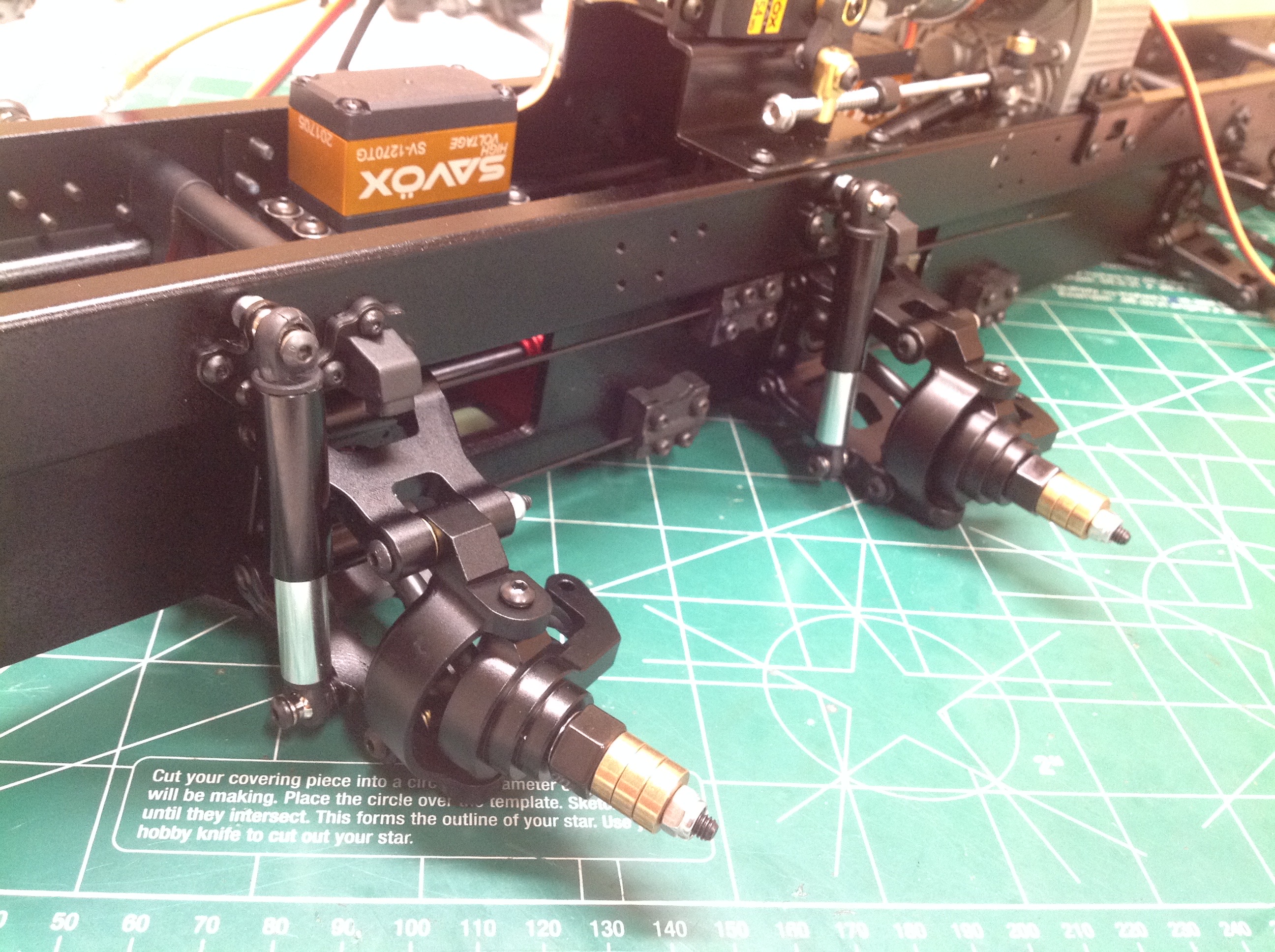
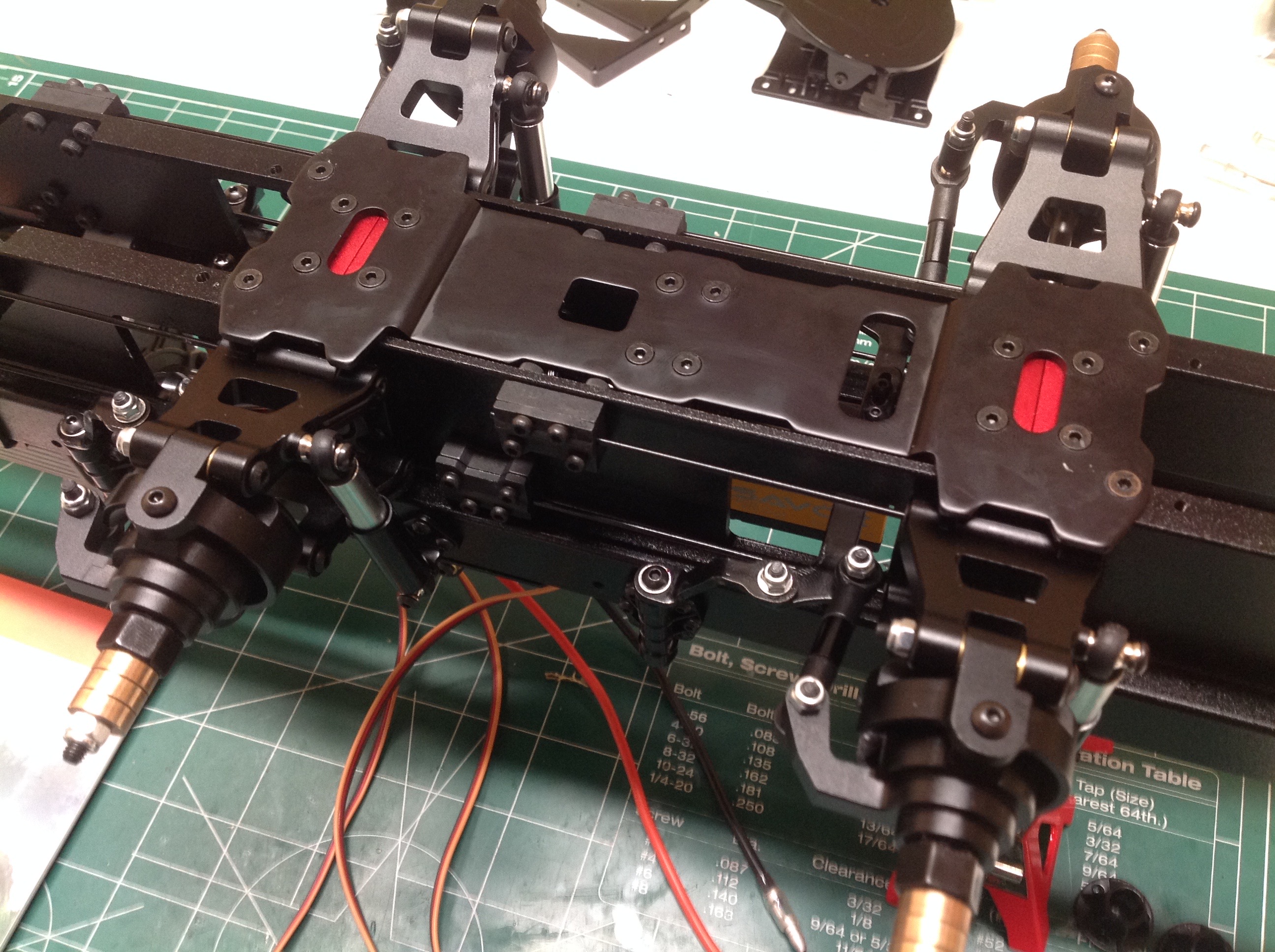
The front axles are suspended using torsion bars. The upper and
lower arms each have their own torsion bars which are set into position
using a jig and then locked with clamp blocks. The shocks you see
in the second image don't really contribute anything to the suspension
but they look good.
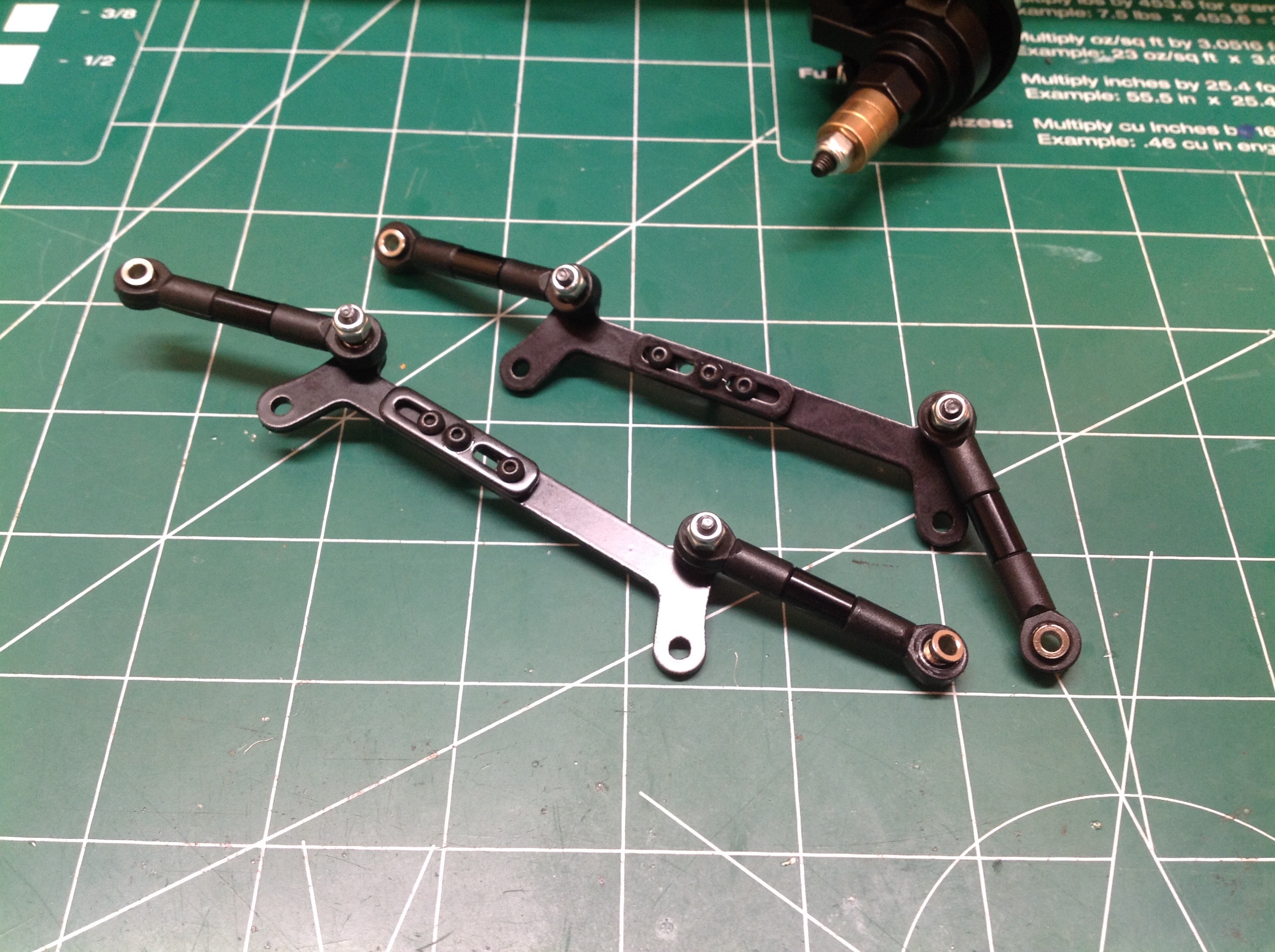
A pair of steering link assemblies connect to the front knuckles.
Crank arms connected to the chassis rails support the links. The
front and rear axle cranks are different lengths to allow the front axle
to steer more than the rear even with the same servo input.
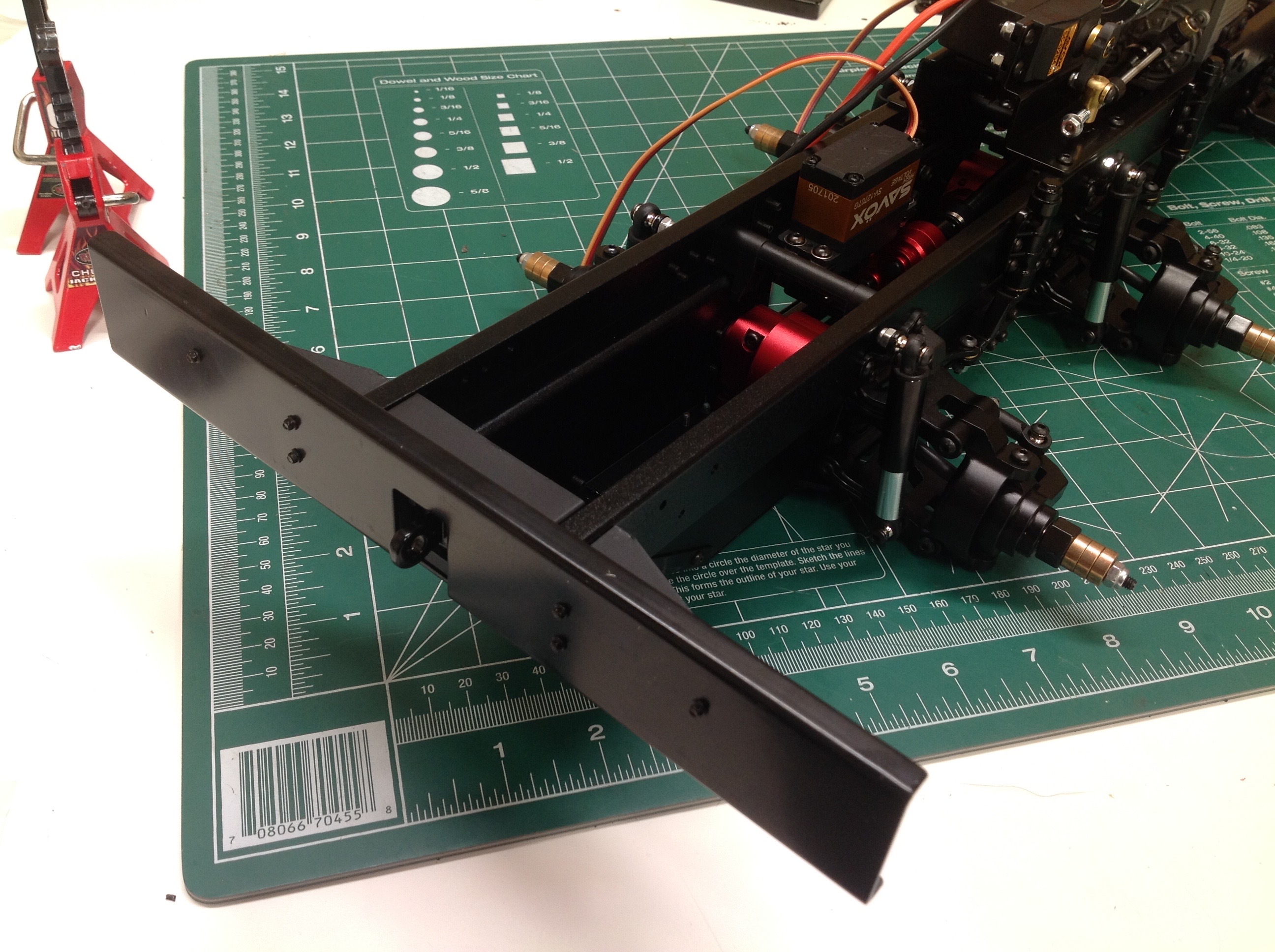
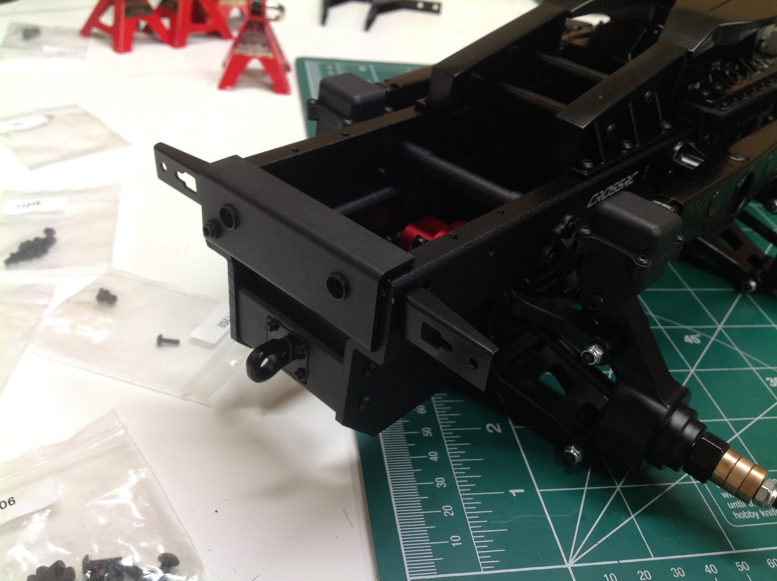
The front bumper is a big flat metal C-channel. It is attached with scale looking hex bolts.
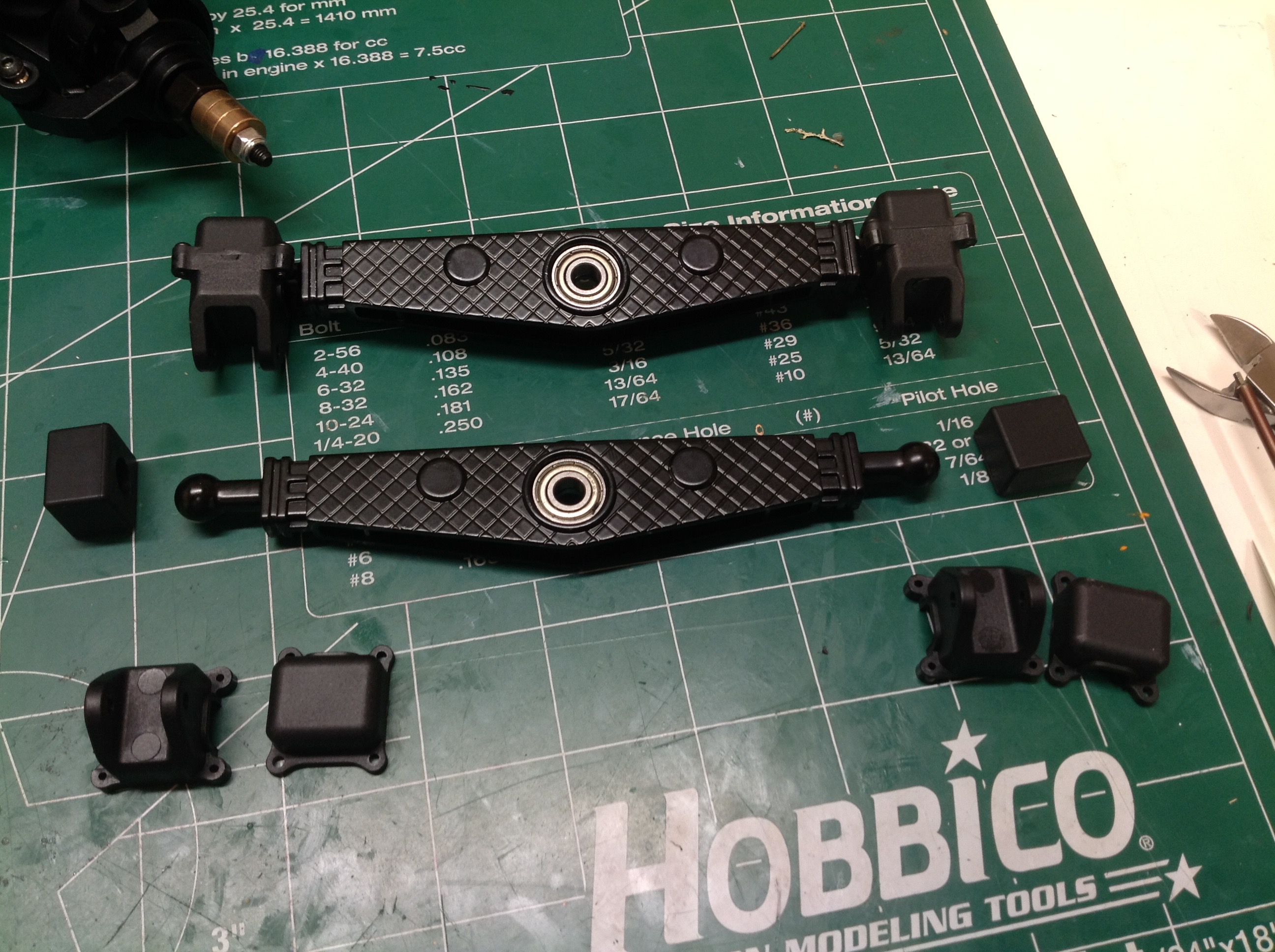
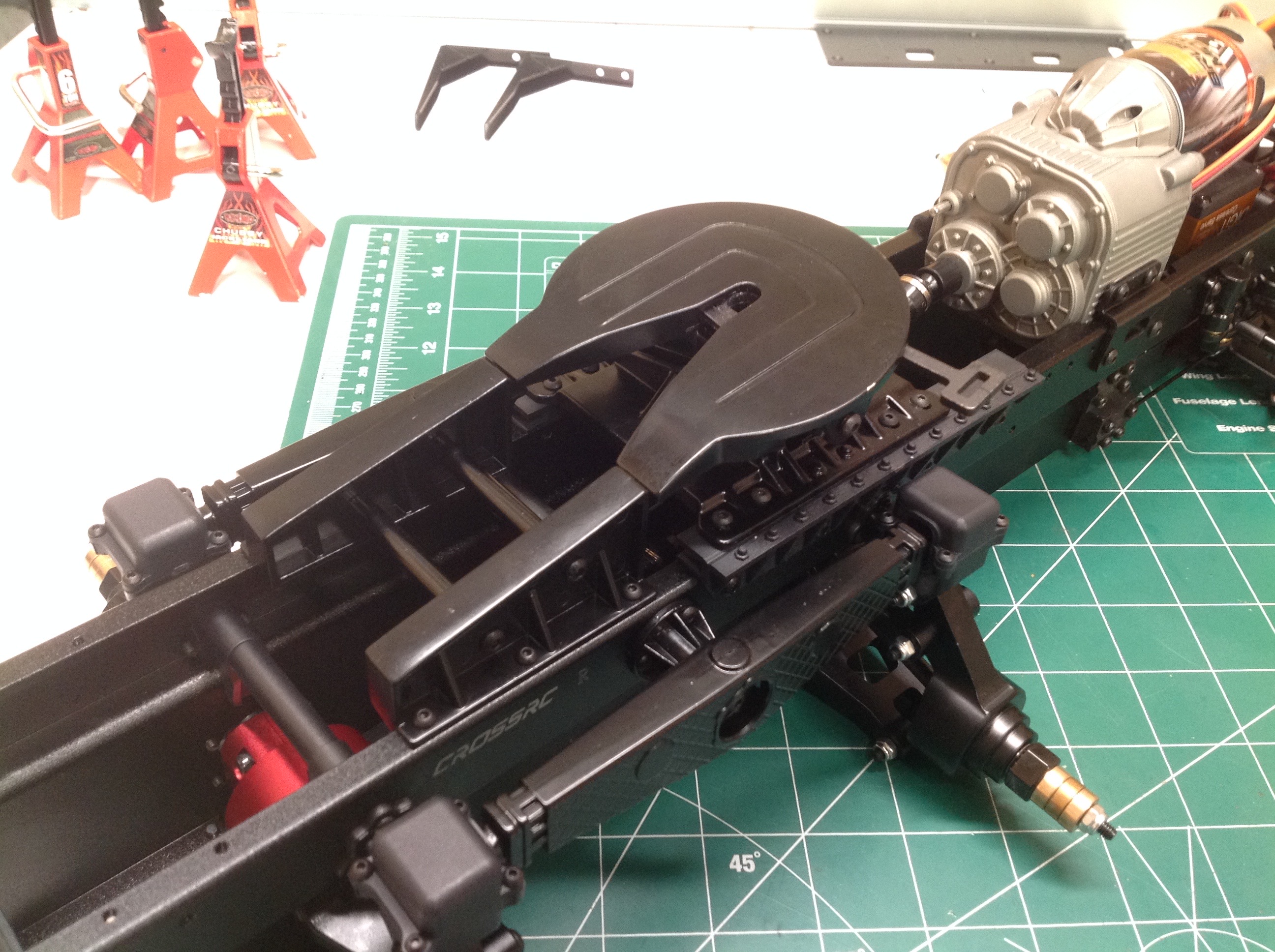
The rear suspension isn't sprung. Instead the 3rd and 4th axles
are connected together with a walking beam. The beam has rubber
bushings on either end to allow rotation without slop or rattle.
The lack of sprung suspension allows the use of trailers with a very
high tongue weight.
Now the fifth wheel assembly is installed. The mounts under it are
among the handful of plastic parts on the chassis assembly. The
right hand image shows the small rear bumper and tail light angle
brackets.
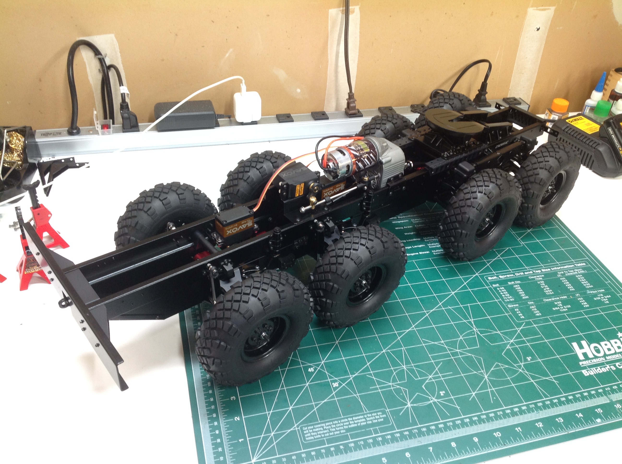
From the bottom the chassis is almost a totally enclosed box which gives
it excellent bending and torsional rigidity. An angled plate in
the front covers the space between the front gearbox and the
bumper. The right hand image shows the completed rolling chassis
sans electronics. It is easily rigid enough to pick up by any
point if you are strong enough to lift it with one hand.
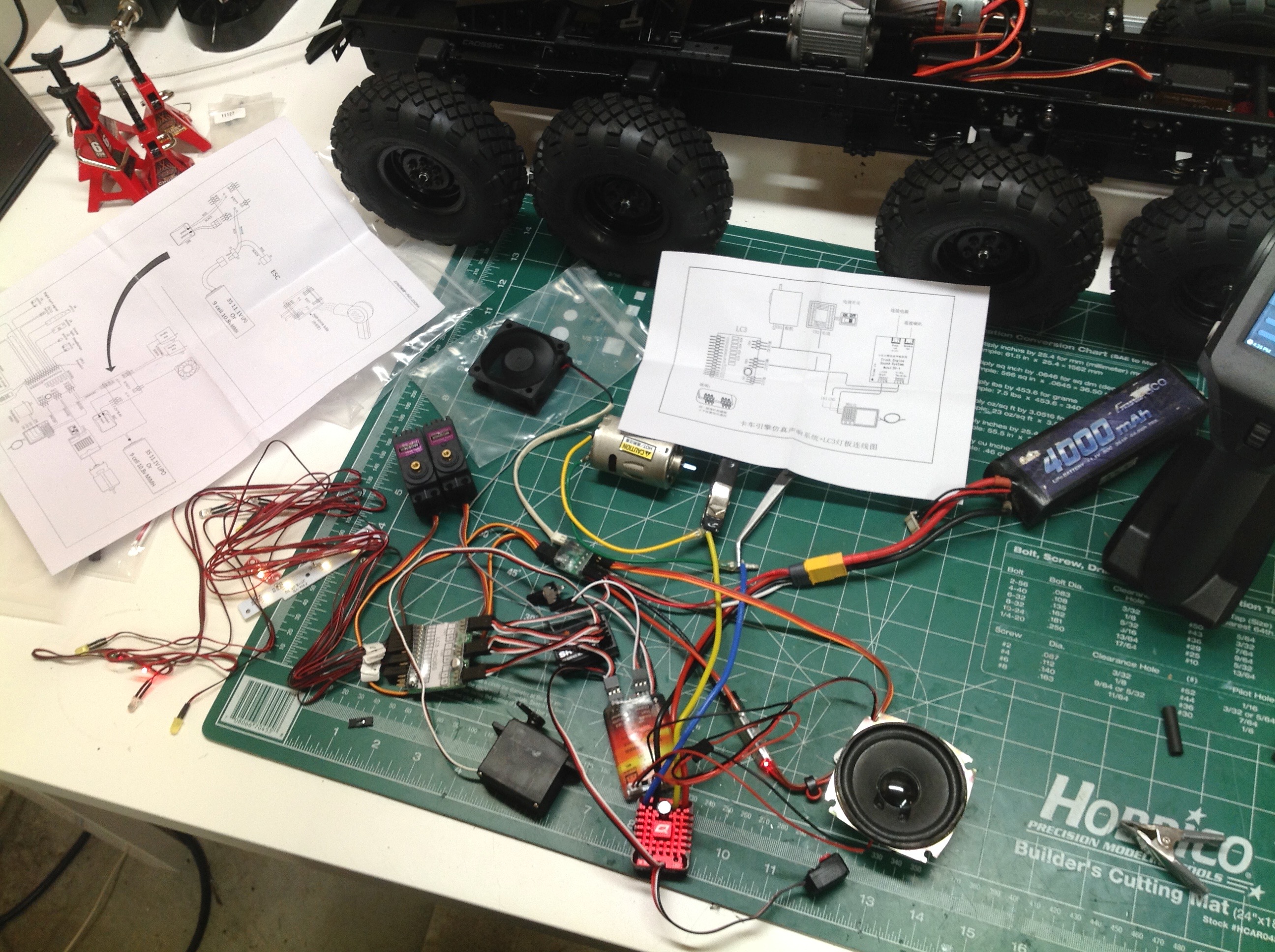
At this point I had to do a test wiring connection to make sure
everything works. The pile on the left is what I had.
Everything does indeed work but it is quite a challenge to
connect. Cross has made it easier by including a PCB to separate
the external BEC power from the ESC power so the BEC can power only the
steering servos and the ESC can power everything else. Luckily the
sound module supports high voltage so I ran it off the BEC as
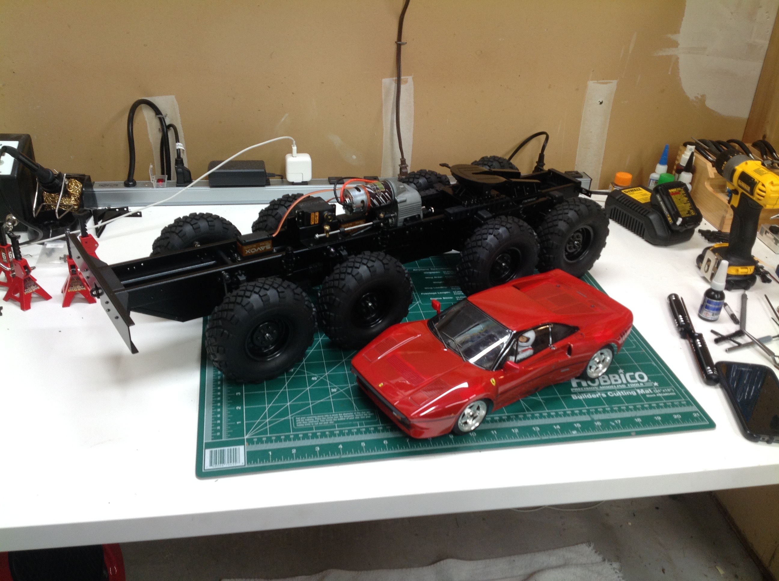
well. The right hand image is a size comparison with another 1/12
scale vehicle. This is a big truck.
©2018 Eric Albrecht