Schumacher CAT XLS Project
Page 1: Assembly
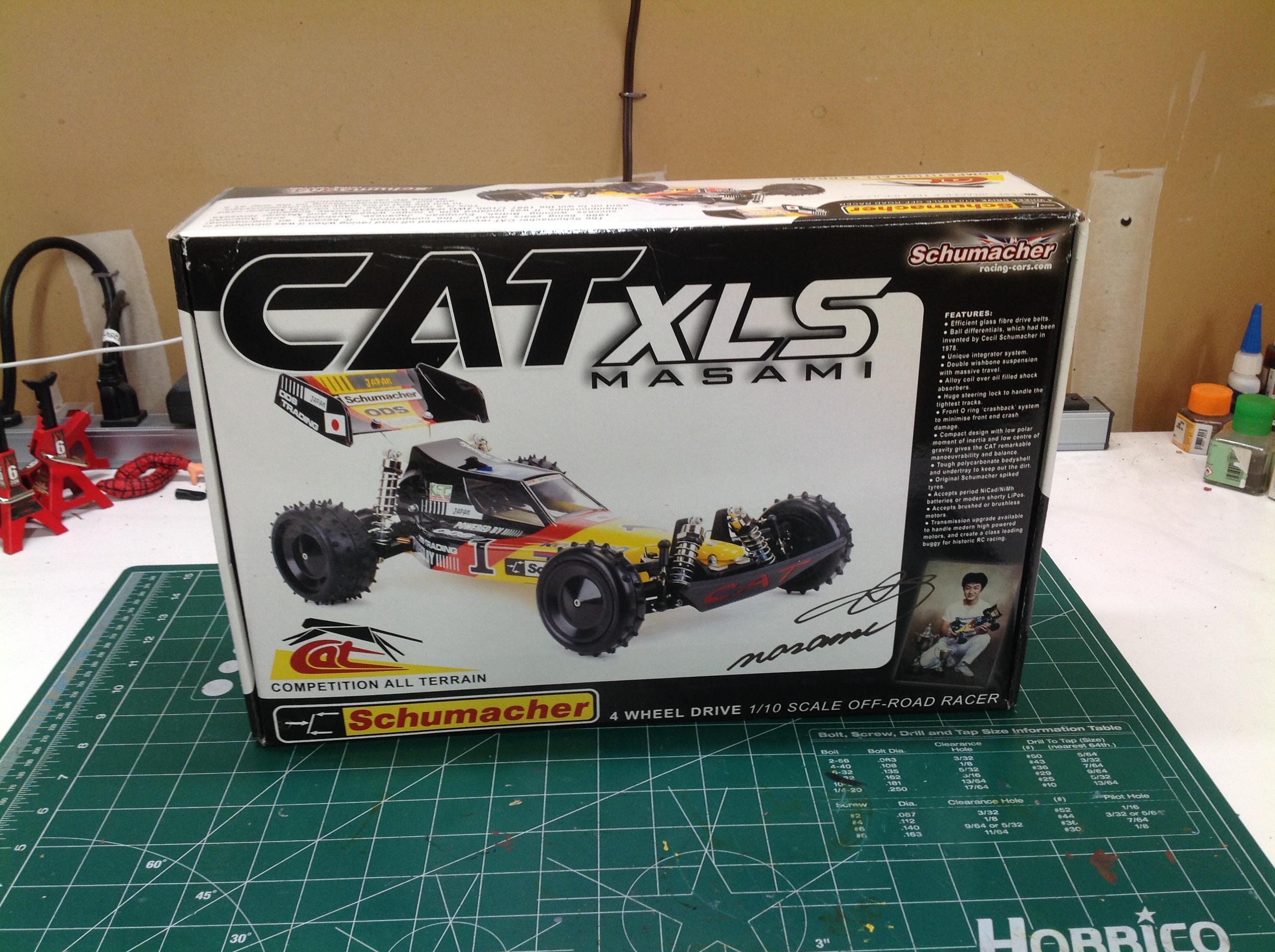
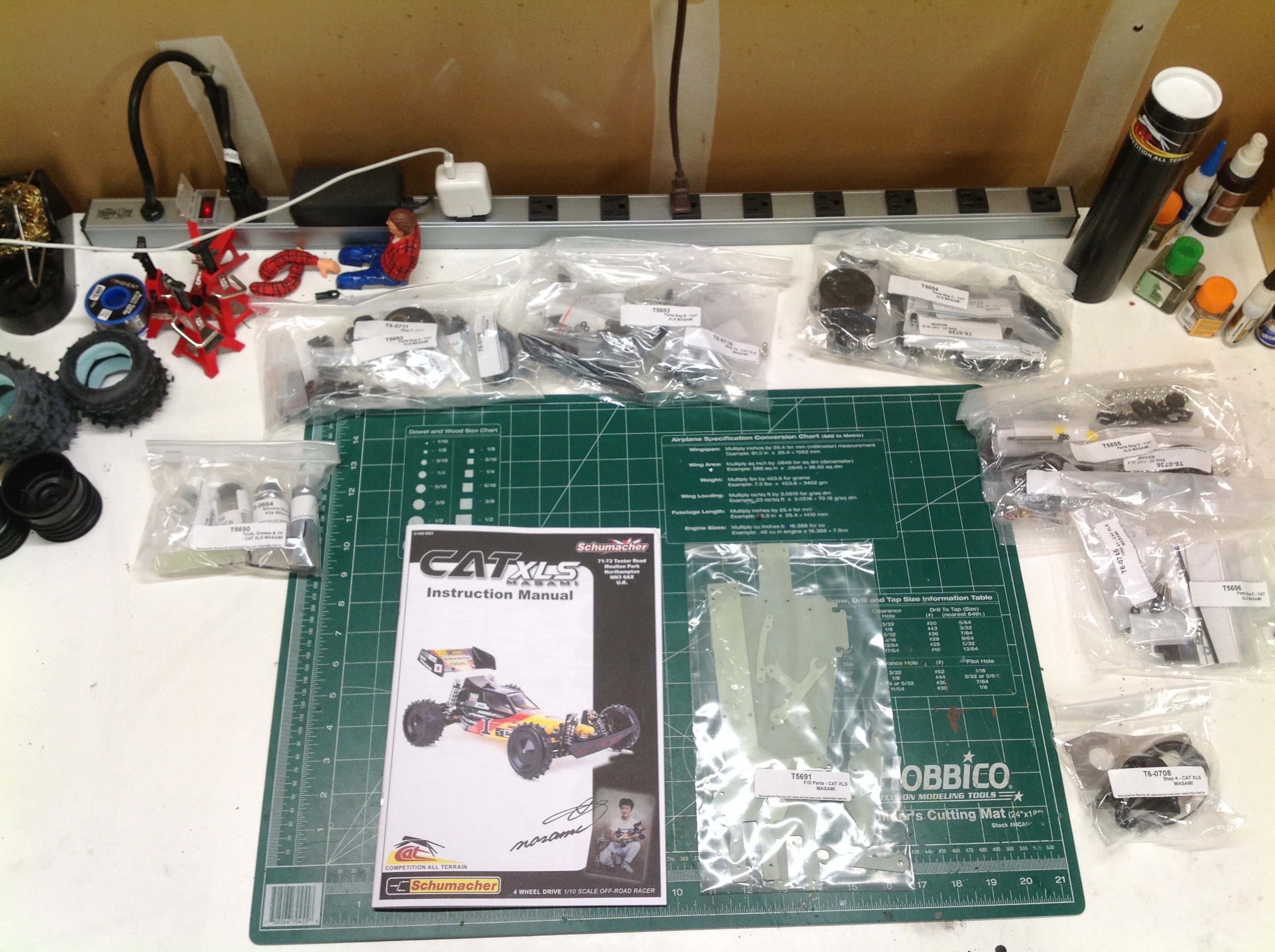
Here is the modestly sized box for the CAT XLS. Inside everything
is bagged in sequenced groups. Each bag contains all the parts and
hardware for a certain number of steps. There are smaller bags
within: one for each step. This makes it very easy to find parts
and proceed with the build.
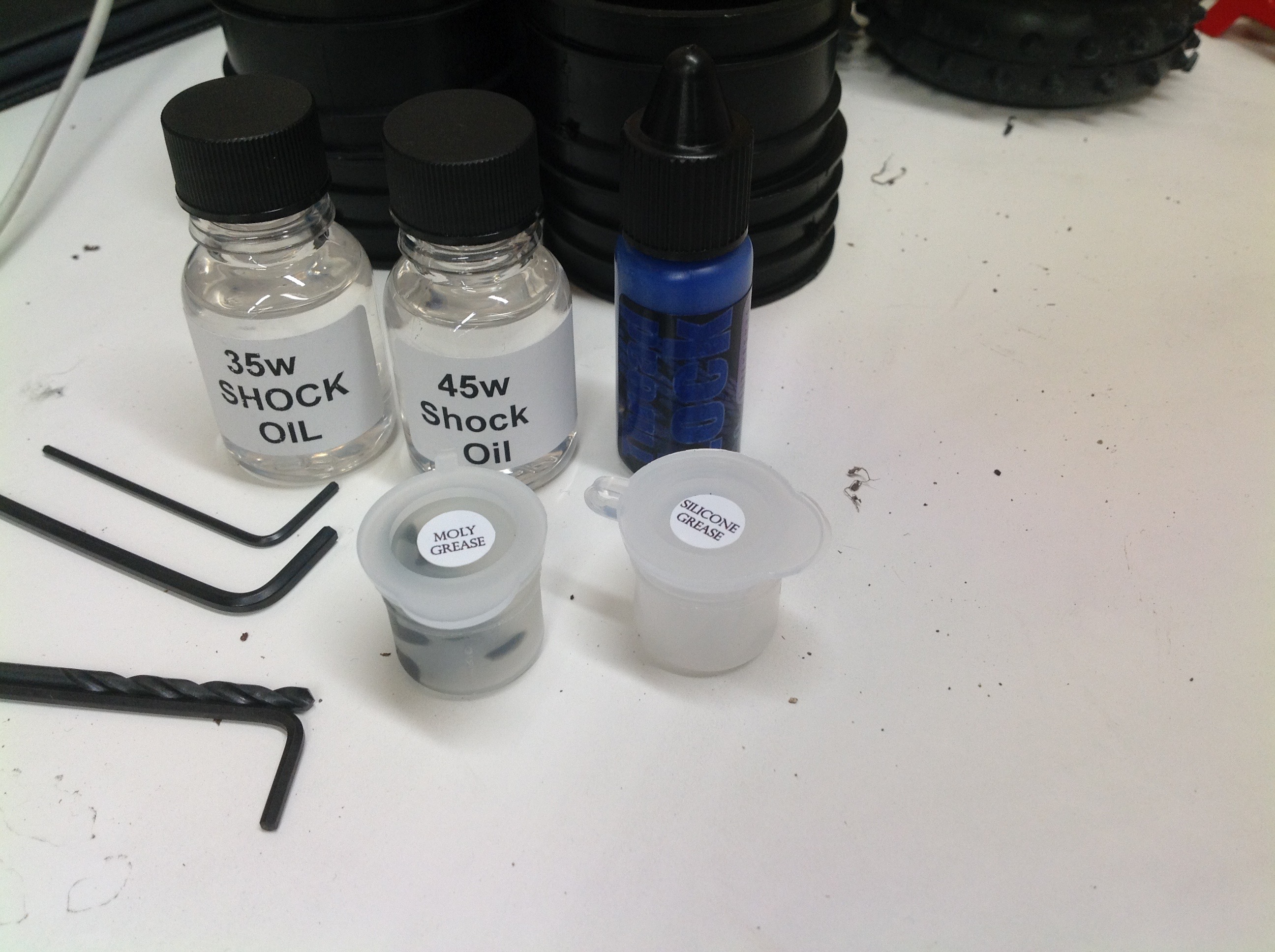
There are also some tools and supplies in the kit. Included are
allen keys, a 3mm drill bit, thread lock, two greases,and two shock oil
viscosities.
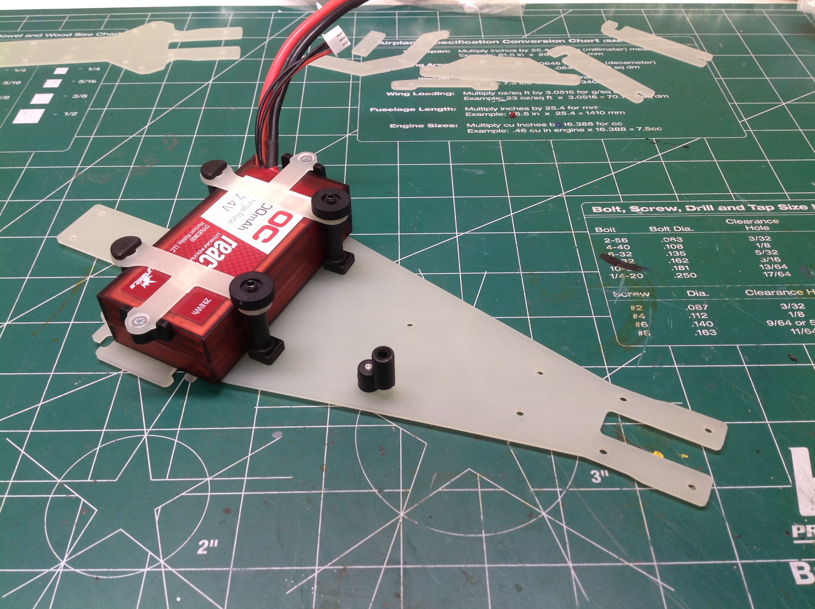
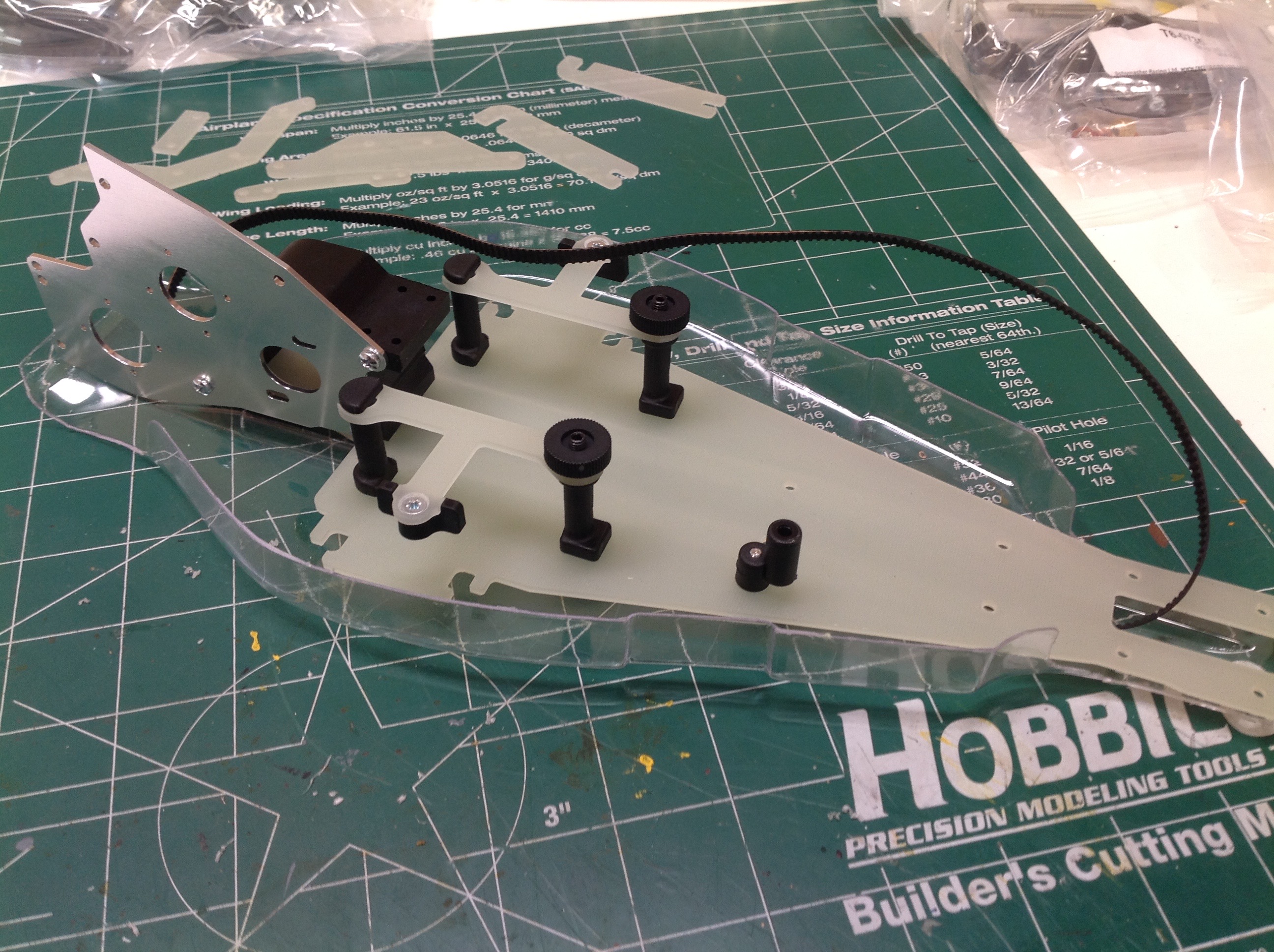
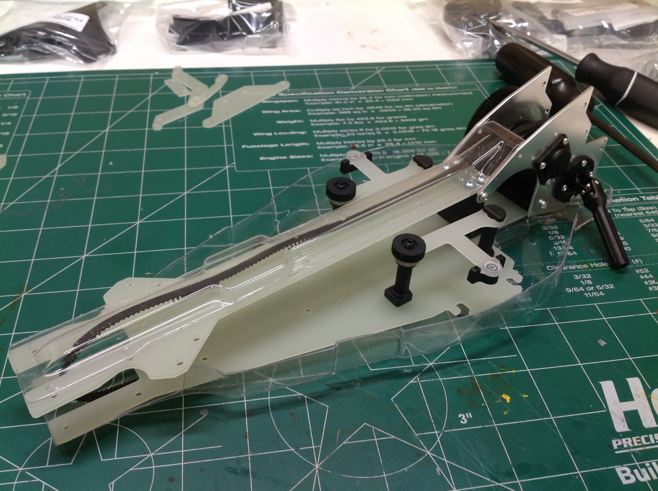
The build begins with the fiberglass lower chassis pan. At this
point a decision has to made as to what kind of battery to use.
You can install rounded straps for a NiMH style pack, or you can install
clamps for a shorty Li-Po pack as I have done. There is also an
antenna bracket installed in this first step. Next we route the
main belt under the chassis pan and then protect the whole thing with an
undertray. The tray gets screwed to the pan and is really locked
in at this point so you can't go back and paint it later. I left
mine clear. The main transmission housing and metal motor plate
are also attached at this time.
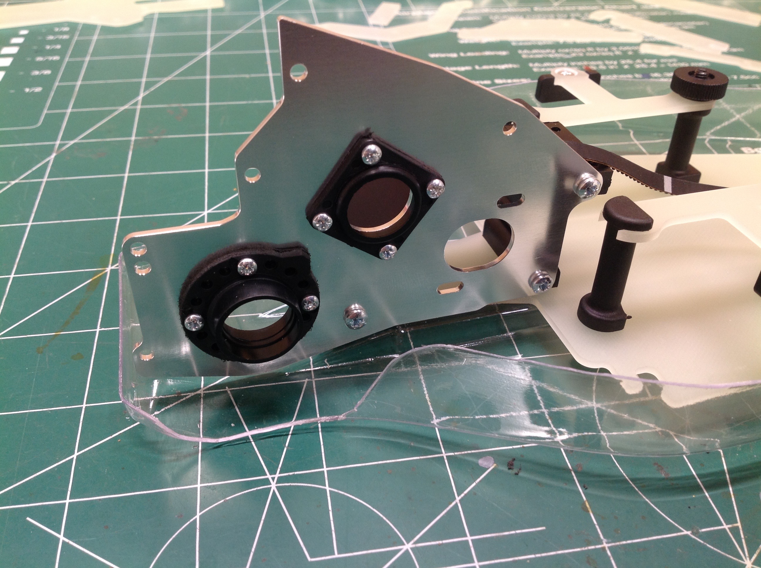
These bearing supports are then attached to the motor mount. The
holes are not tapped; these are very short sheet metal screws. The
lower support is a cam and can be rotated to adjust belt tension.
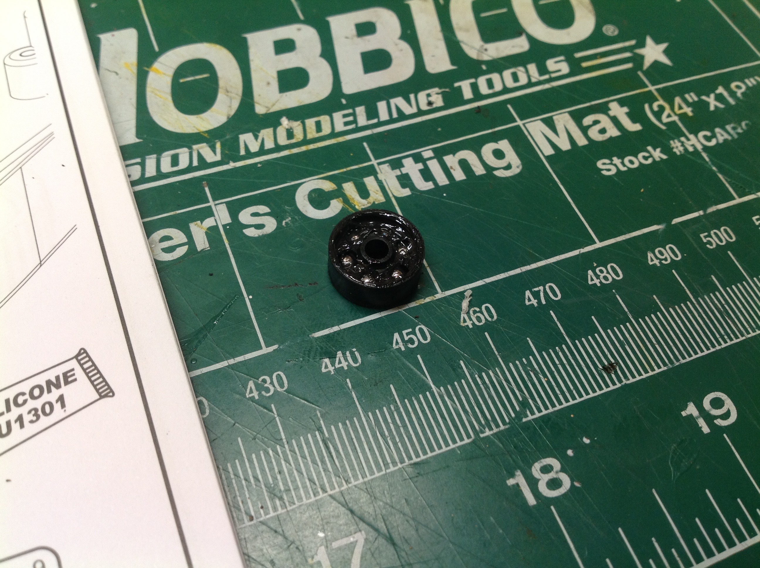
Time to build the first of many ball differentials. This design
was apparently invented by Schumacher. The small ball diff goes on
the upper shaft which will connect to the spur gear at the other
end. At this end it drives two pulleys which will connect to the
rear left and right wheel pulleys.
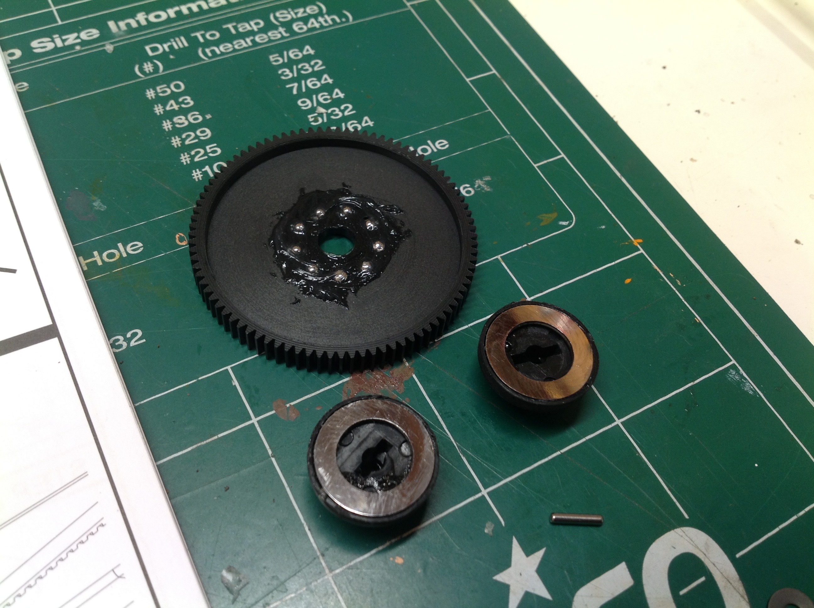
This second ball diff looks much bigger, but the balls are actually the
same size. Only the outer gear diameter is bigger. This is
the 48p spur gear. The raceway washers have to be manually glued
to the plastic parts. This is a bit tricky to do without getting
glue anywhere it shouldn't be. This is both a slipper clutch and
also a torque
splitter. Each side of the slipper is connected to a different
side of the first ball diff.
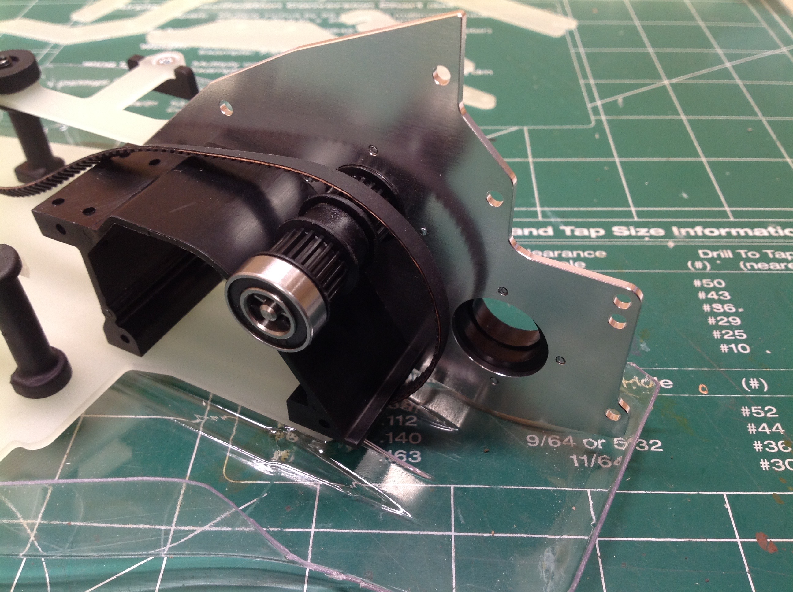
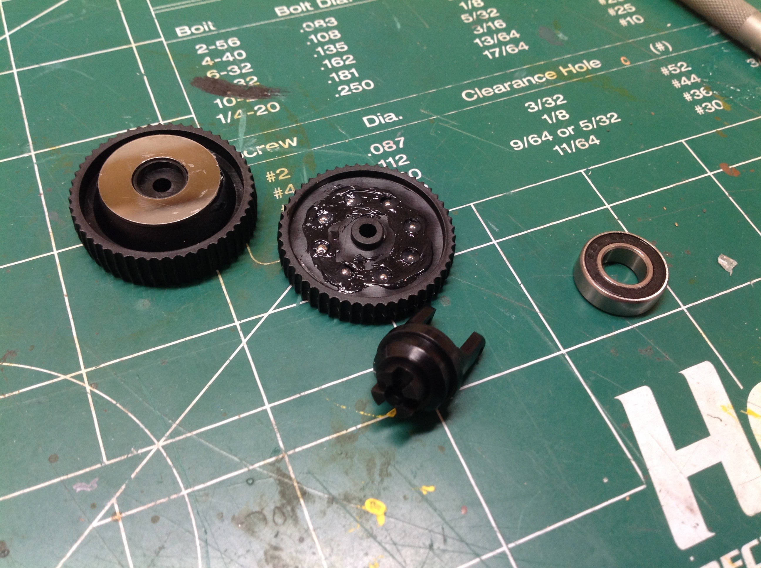
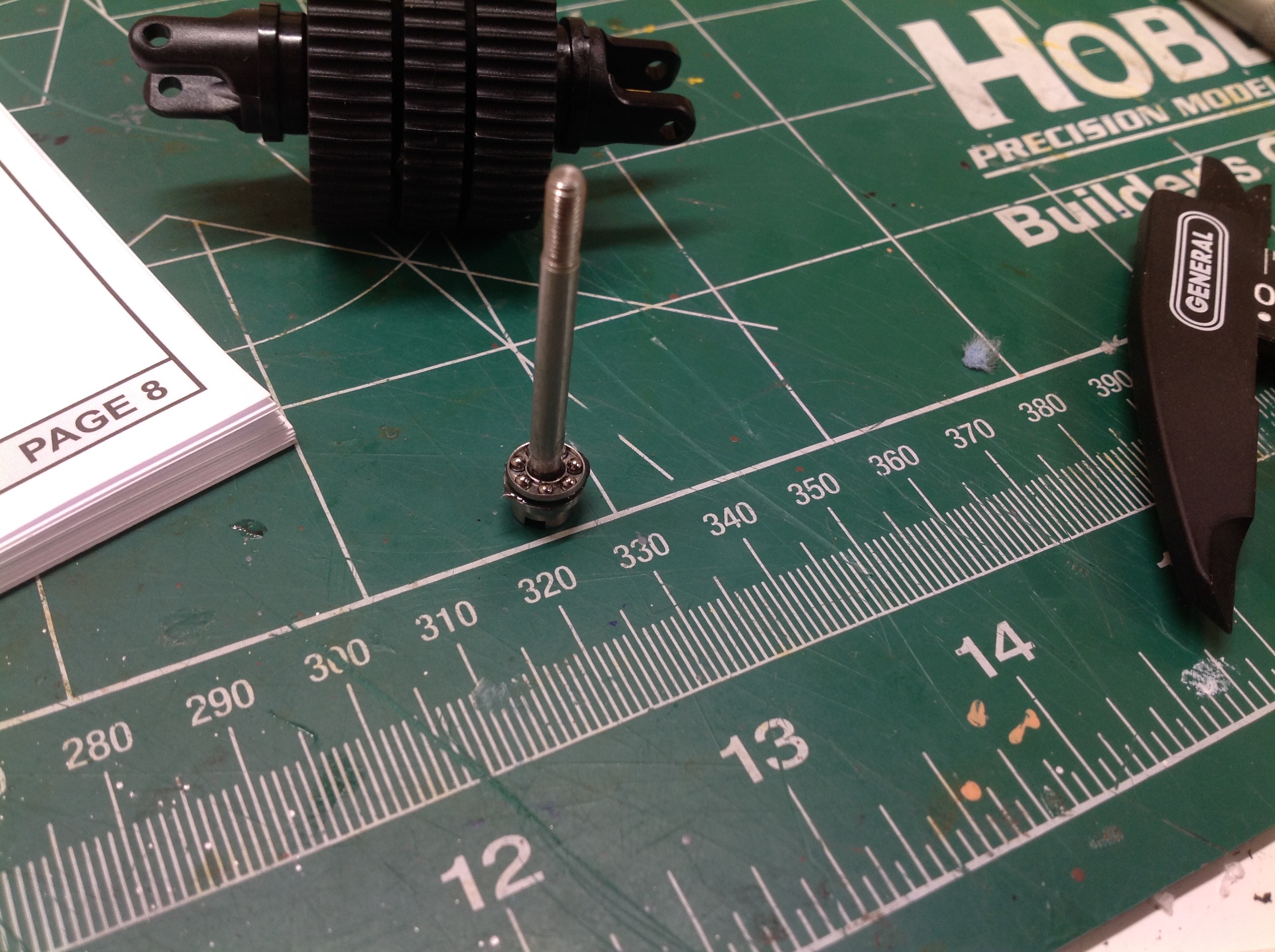
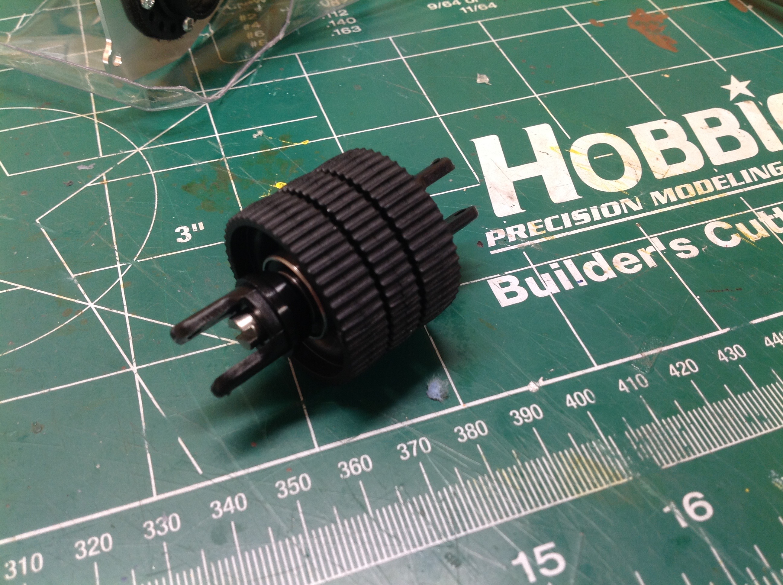
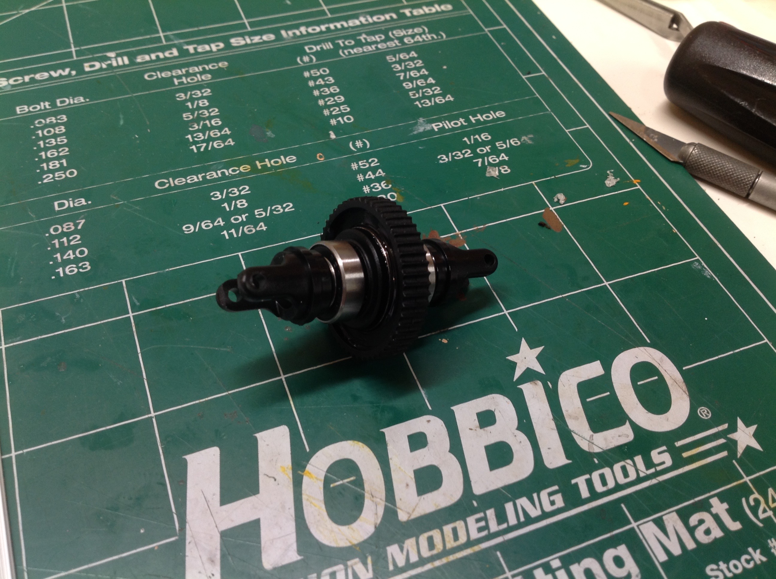
Now for the rear ball diff assembly which the instructions call the
"Integrator". This serves as a combination rear differential and
center differential. On the right you can see the tiny balls in
the thrust bearing assembly at the base of the long bolt.
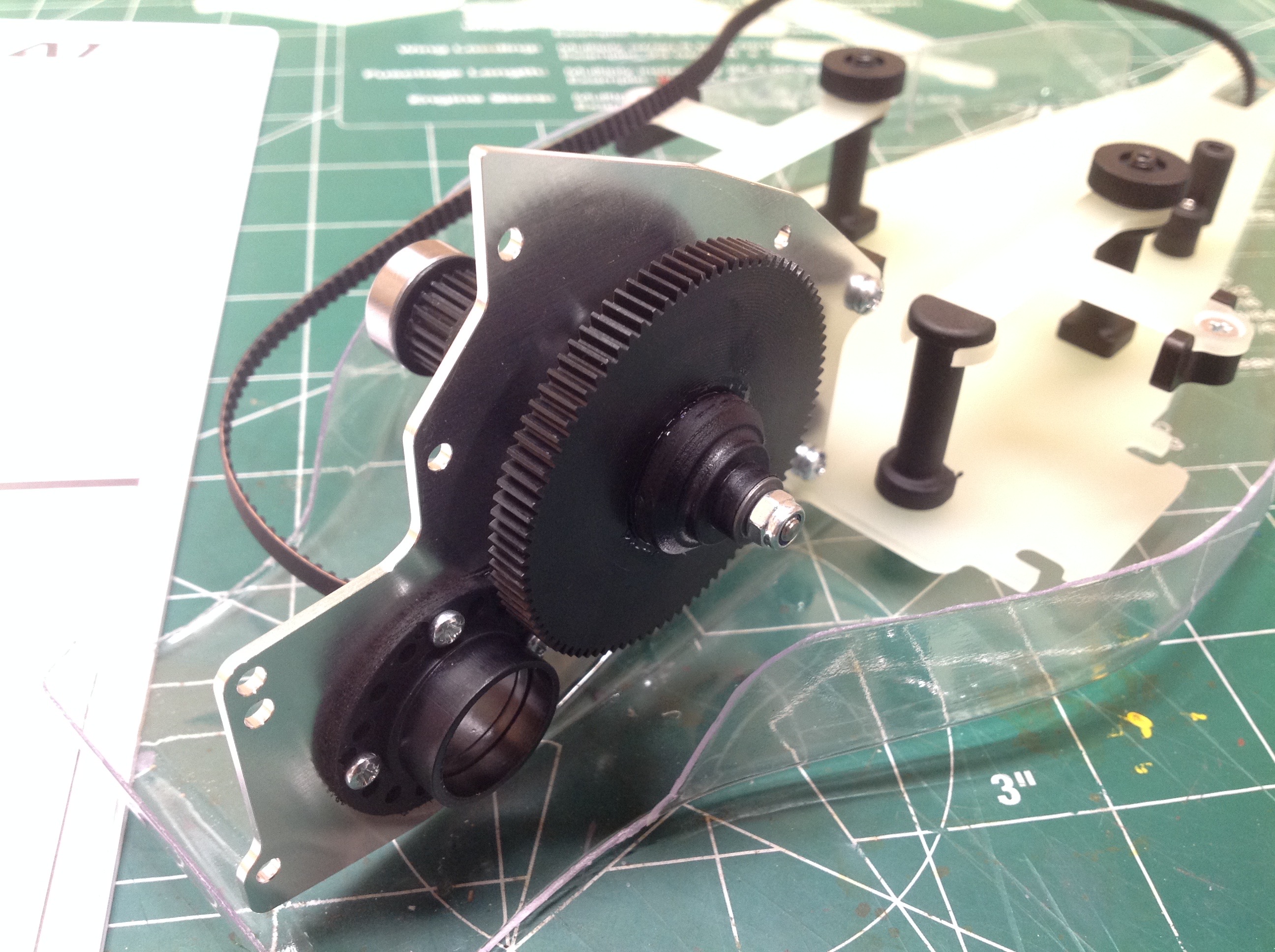
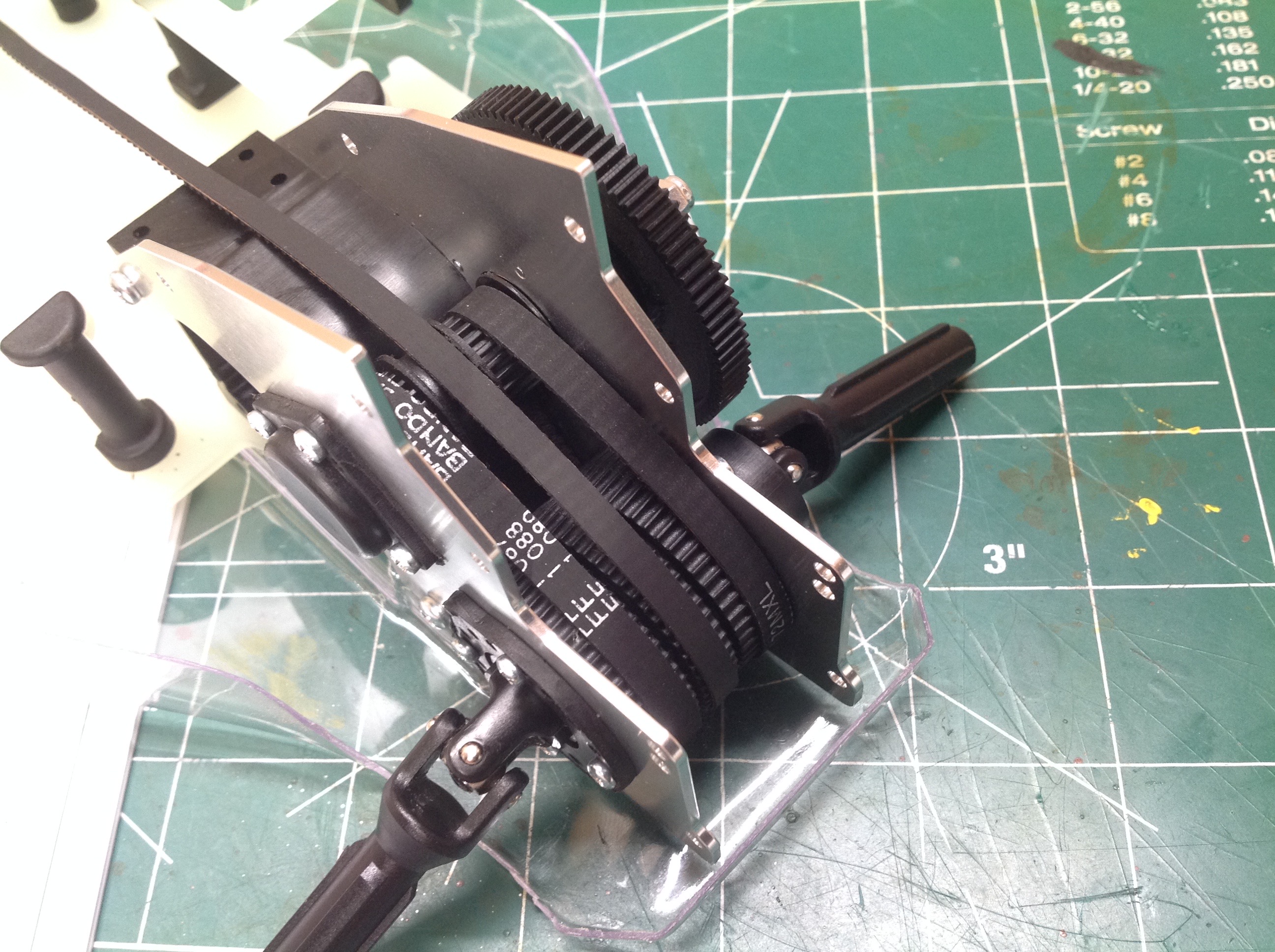
The final integrator has three pulleys and it is not immediately obvious
what they are for until the unit is installed in the chassis. On
the right you can see the two small belts which connect the spur gear
differential to the integrator. This allows the motor to drive the
rear wheels even if one is slipping. The center pulley connects
to the long belt which will go to the front wheels. Because it
averages the left and right pulleys, it will always be proportional to
the motor. The purpose of driving the front wheels from the lower
pulley instead of using the upper shaft is to take advantage of the
reduction first.
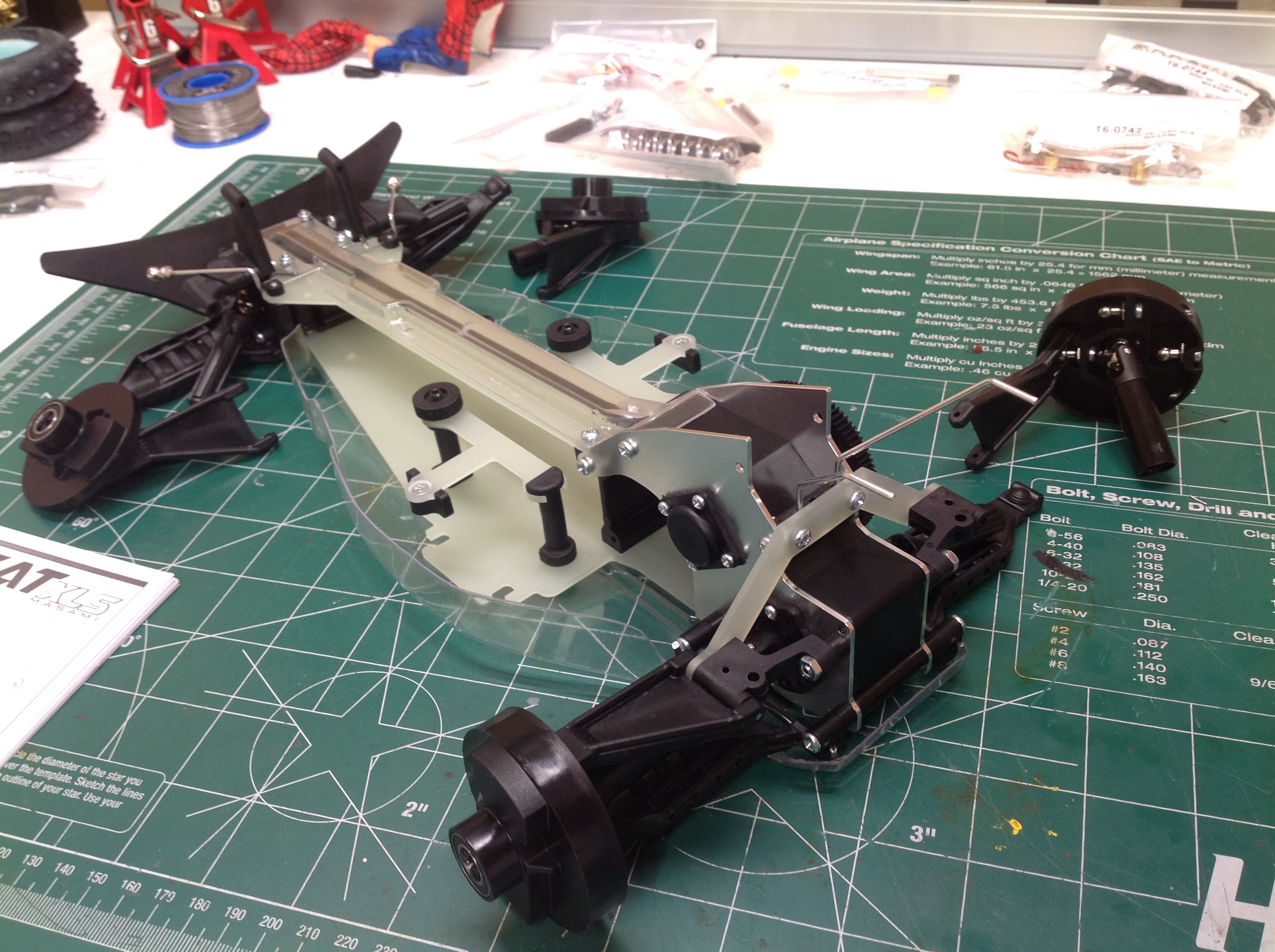
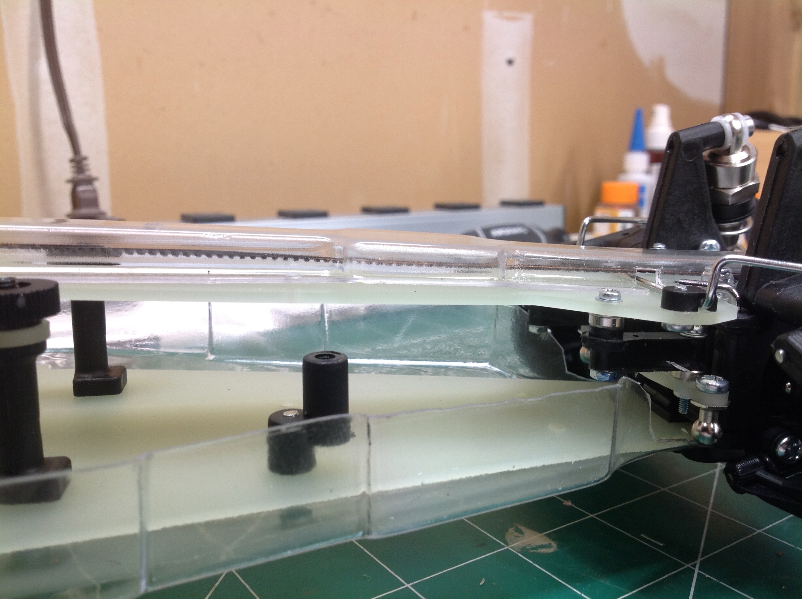
Now a cover has been installed over the integrator assembly to protect
the belts. Then the upper chassis plate has been installed along
with a protective clear belt cover.
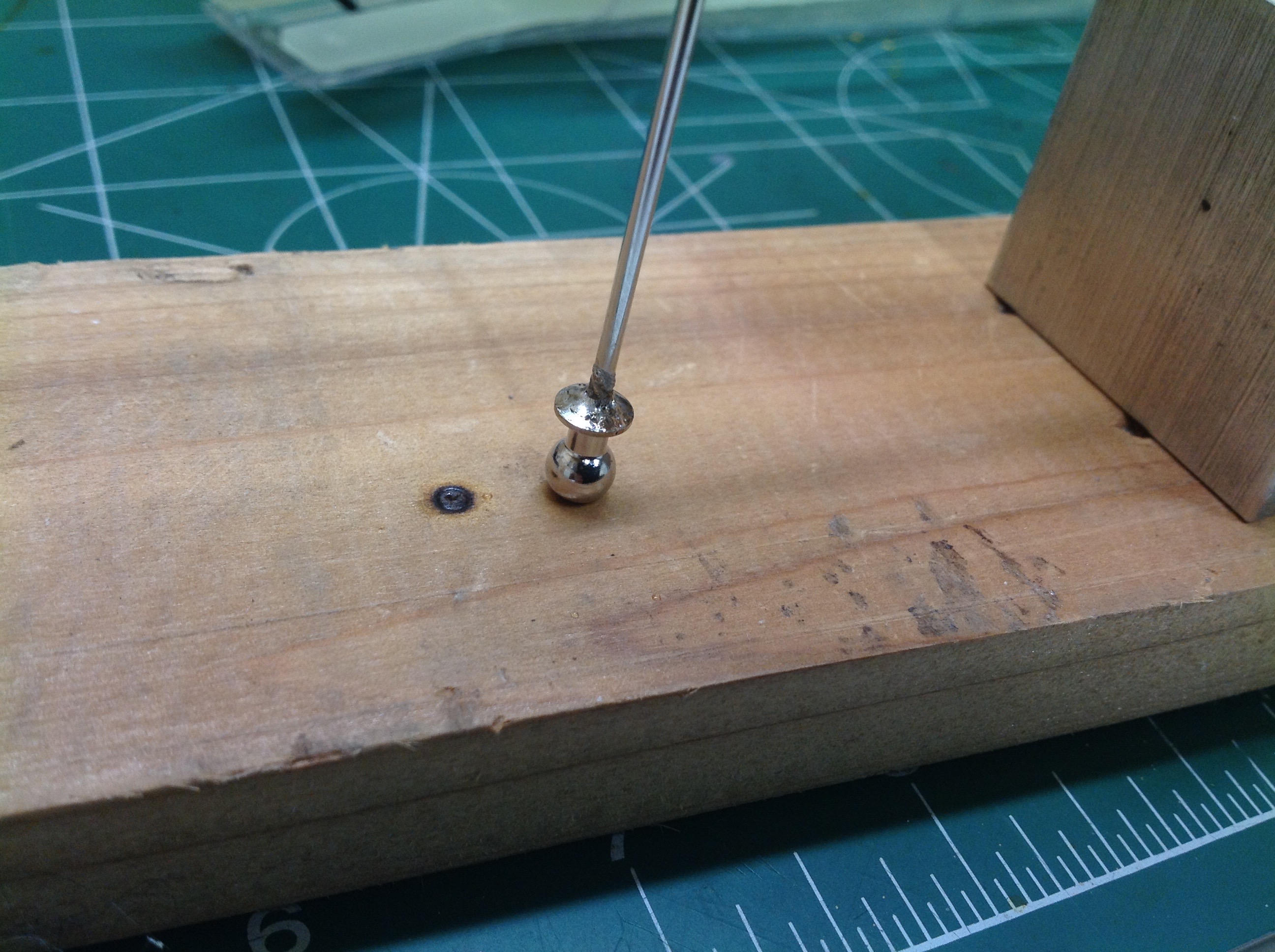
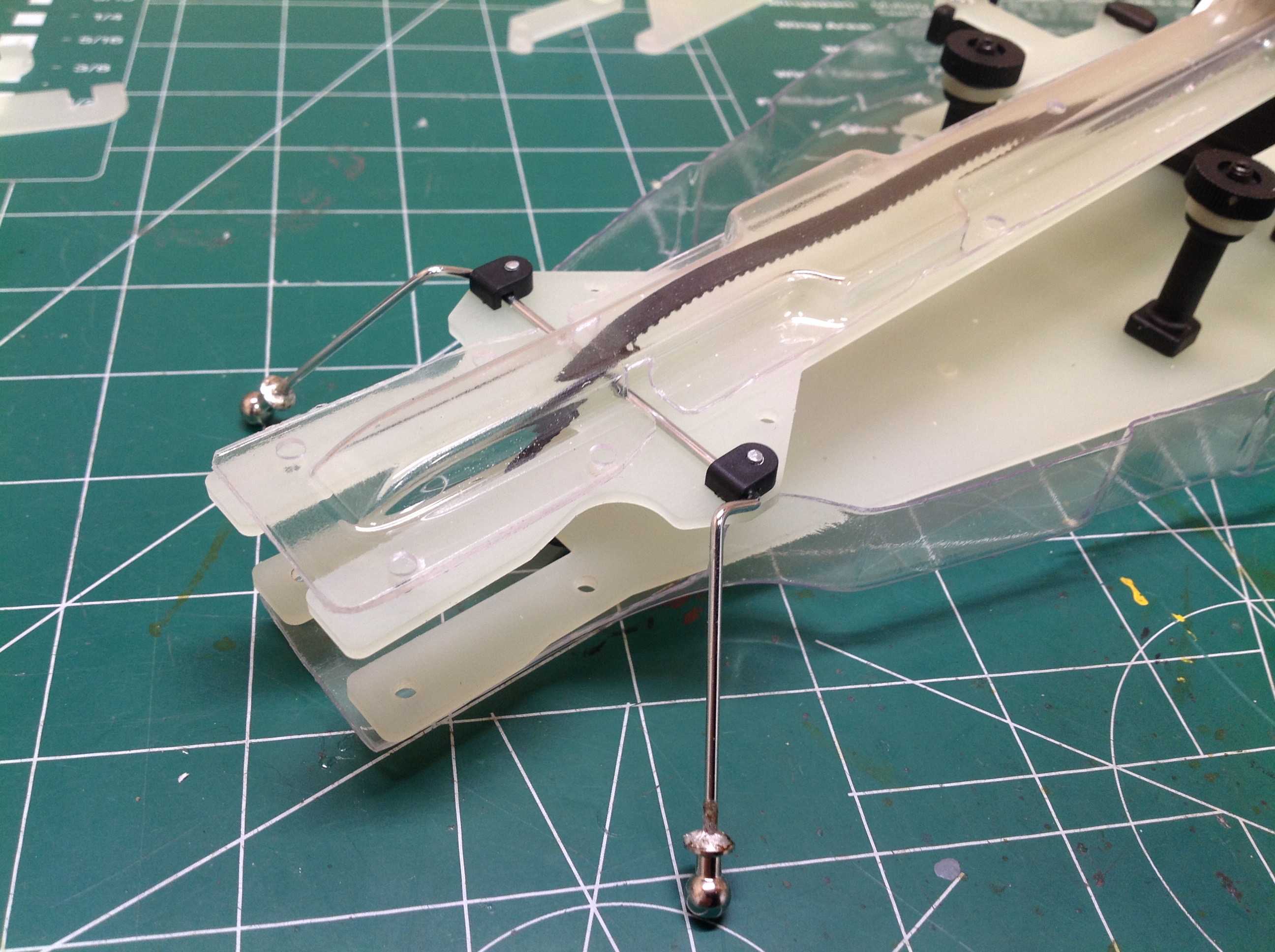
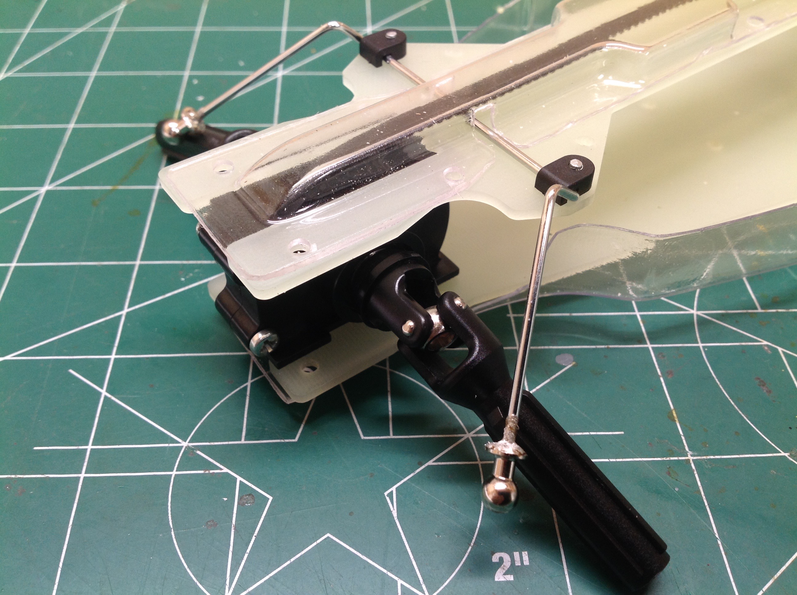
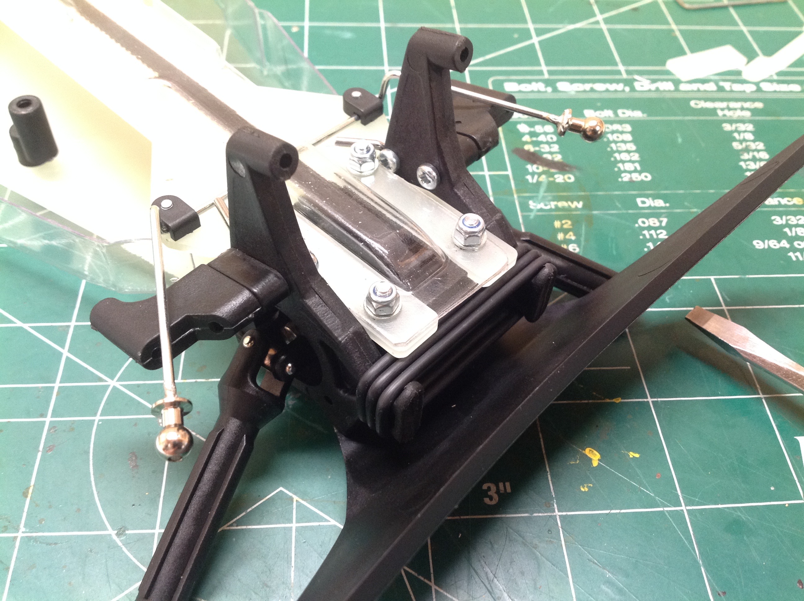
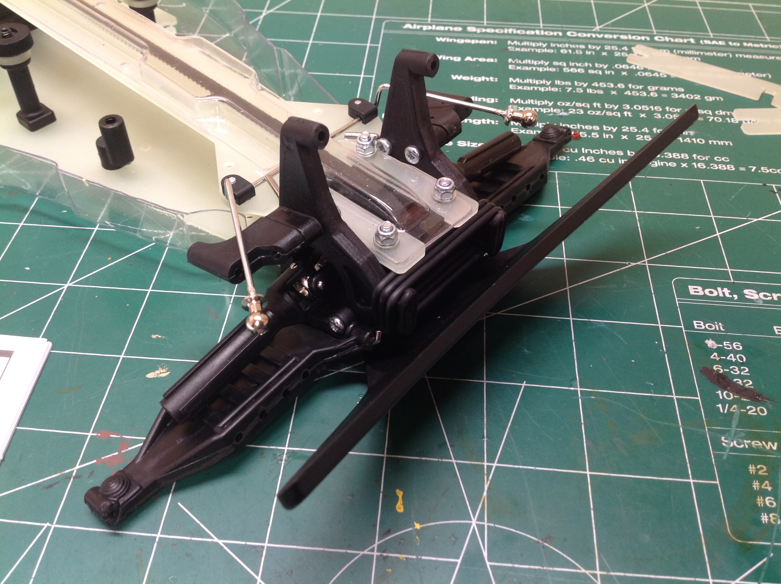
Here's an unusual assembly step. The ball joints on the sway bar
are attached by soldering rather than using a more standard set
screw. No big deal if you have a soldering iron, but might be a
problem for newer builders. The sway bar attaches to the upper
chassis plate with small plastic brackets acting as hinges.
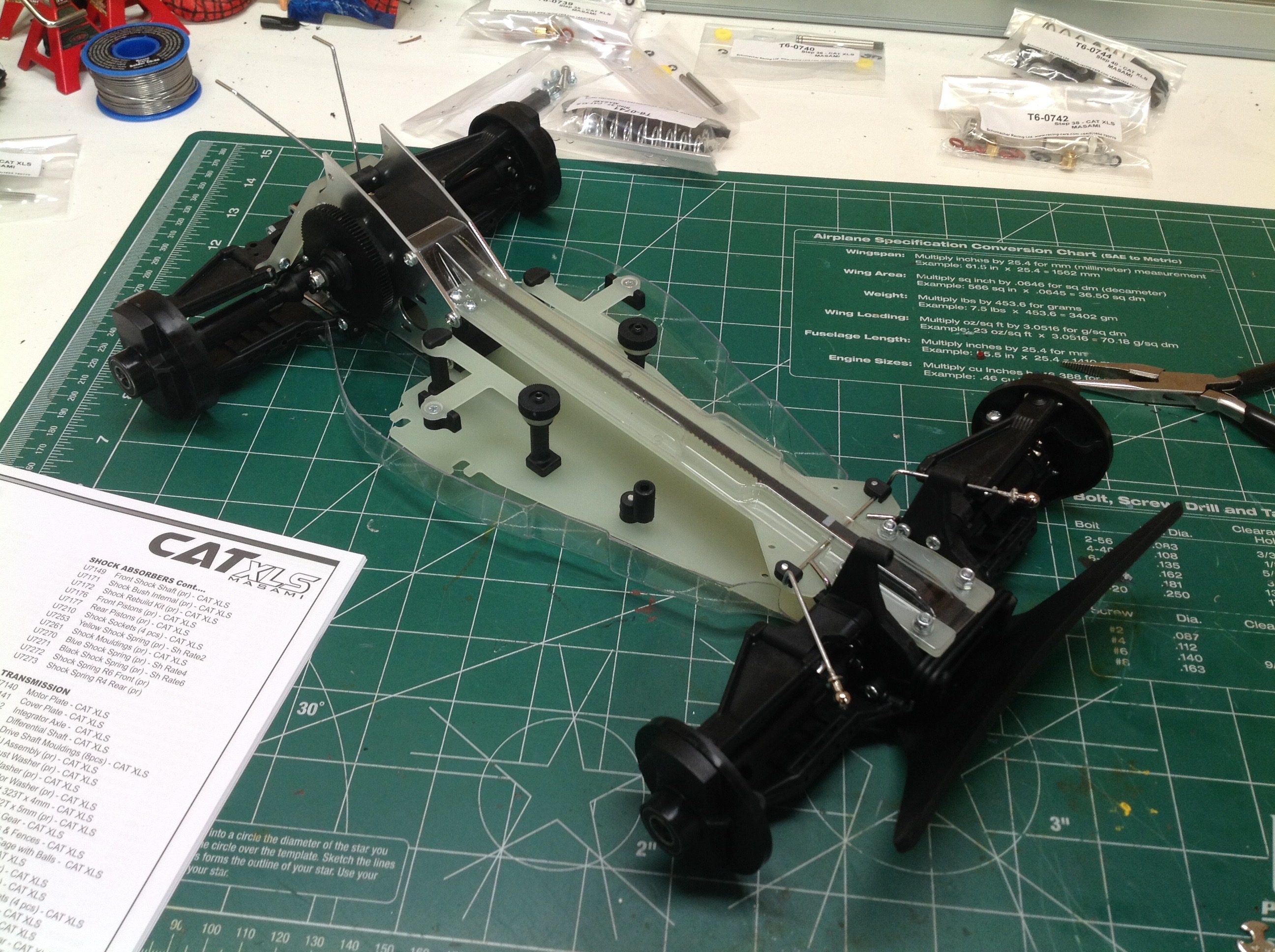
The front differential is the simplest ball diff we'll build. It
is pretty standard and contains a pulley for the long belt in the
center. It is then installed between the upper and lower chassis
plates.
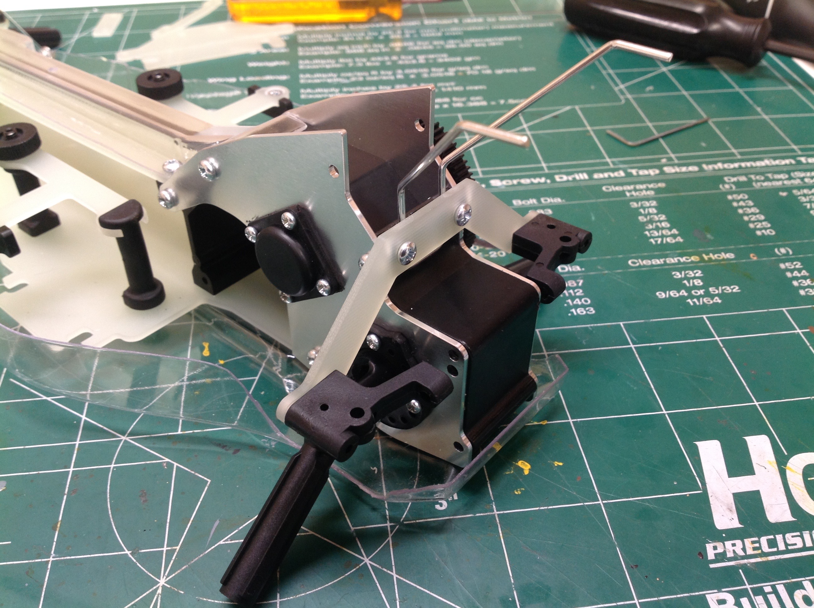
Now we'll do a bit of work on the front suspension. The universal
joints need to be manually assembled which is tricky. You need to
use a special tool to pry open the yoke and insert the cross. Then
the front bumper is installed with long bolts that go all the way
through the differential housing.
The rear suspension follows next. The rear drive shaft universal
joints are built in the same way as the front. Next the lower
control arms are installed with a long wire as a pivot axis. There
is a lot of cross bracing in the back to keep everything nice and
rigid.
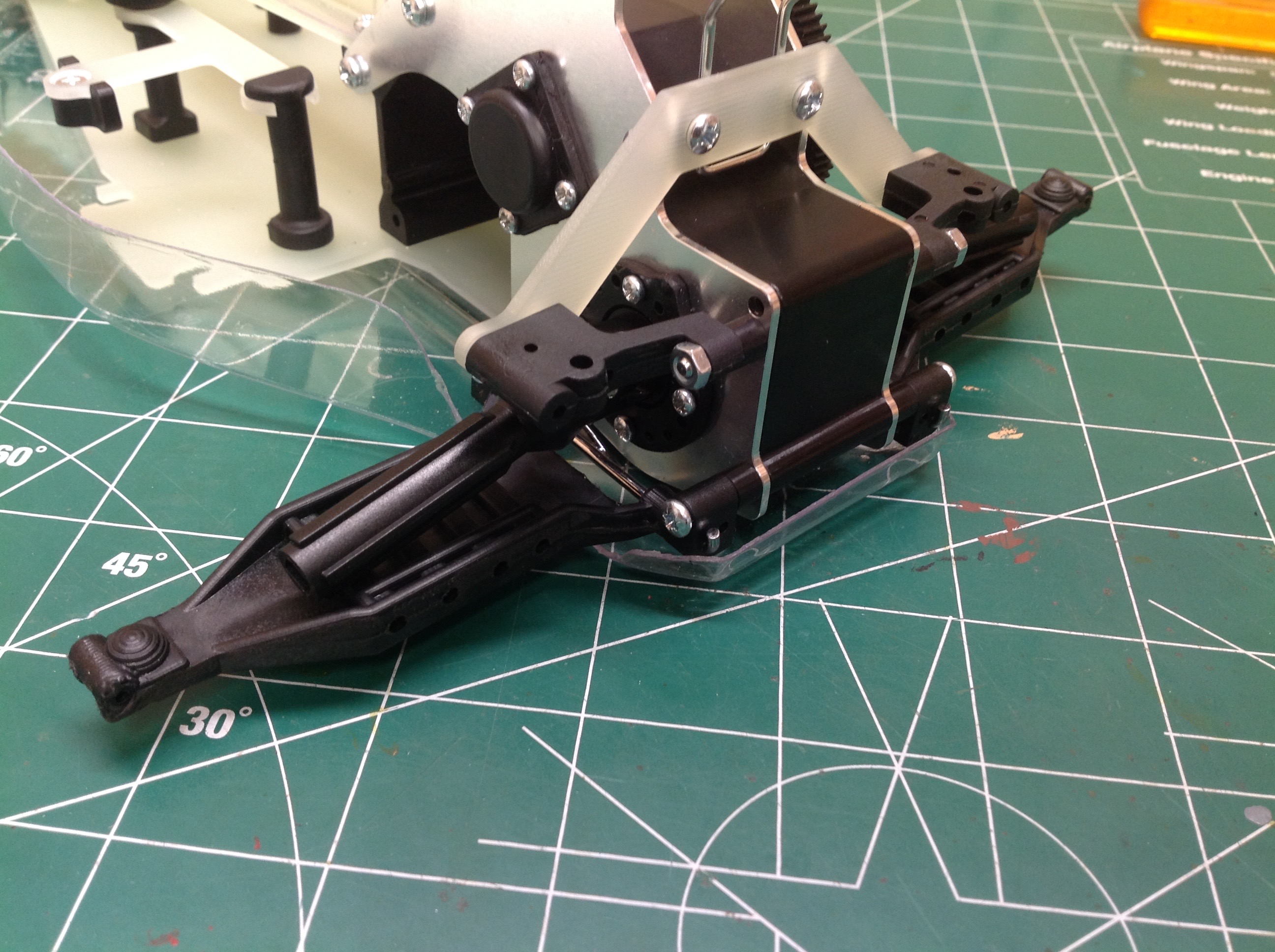
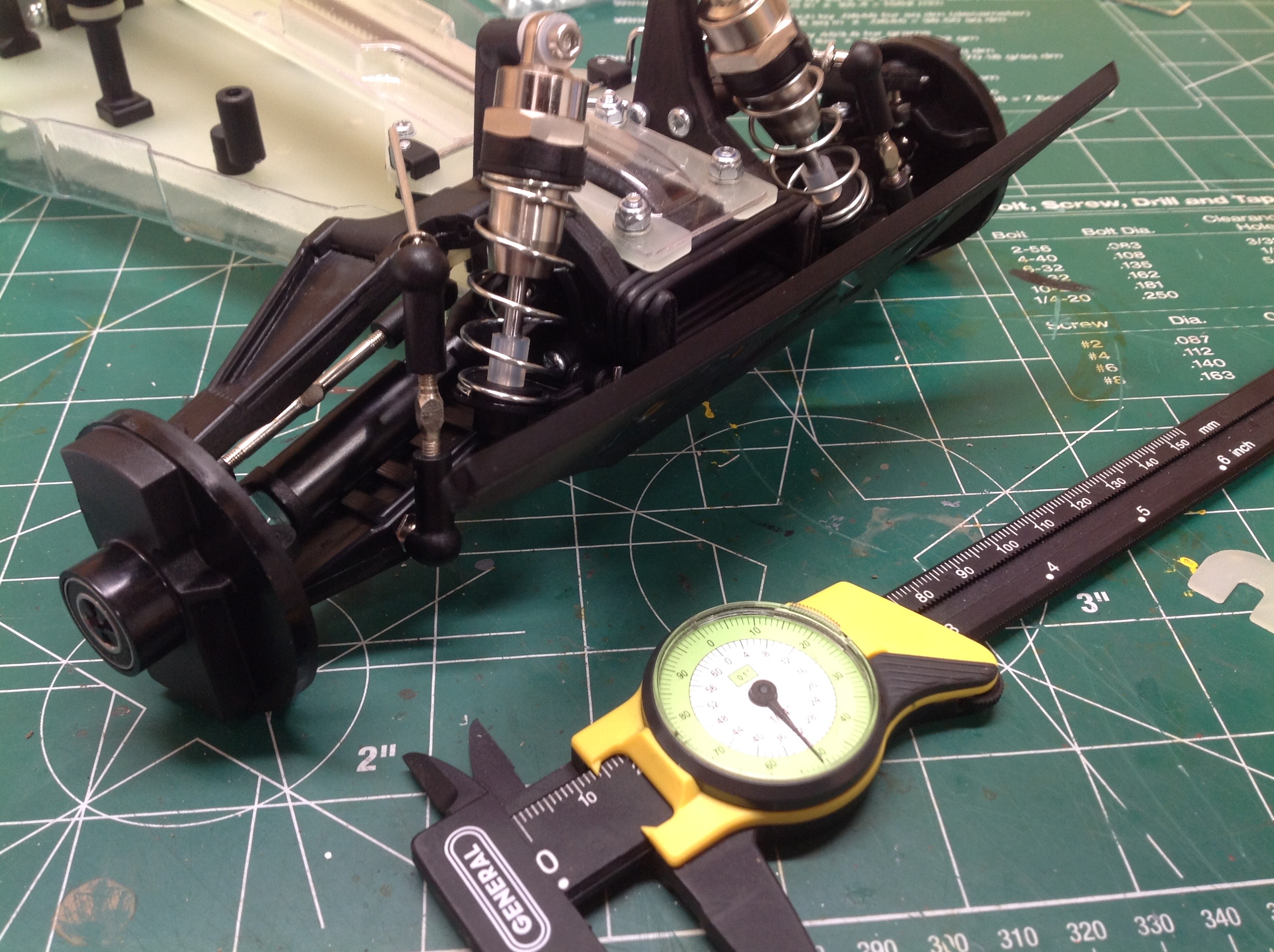
The front lower arms are installed much like the rear. They are
very long one-piece arms. I've also installed the shock
towers. The 3 big black rubber bands you see right behind the
bumper are the crash relief system. This allows the wheels to
splay outward if a front tire hits an obstacle. The bands are
stiff enough that they won't effect normal driving.
All four upper arms go in next and then the hubs are installed.
These are not your typical C-hub design. The hubs are large discs
the size of the inside diameter of the wheels. All of the ball
joint sockets point down. This ensures that nothing can pop out
when you get big up forces from jumping, but it also makes things a bit
difficult to assemble. The second half of the drive shaft is
attached to the hub and slides over the splines on the inner shaft.
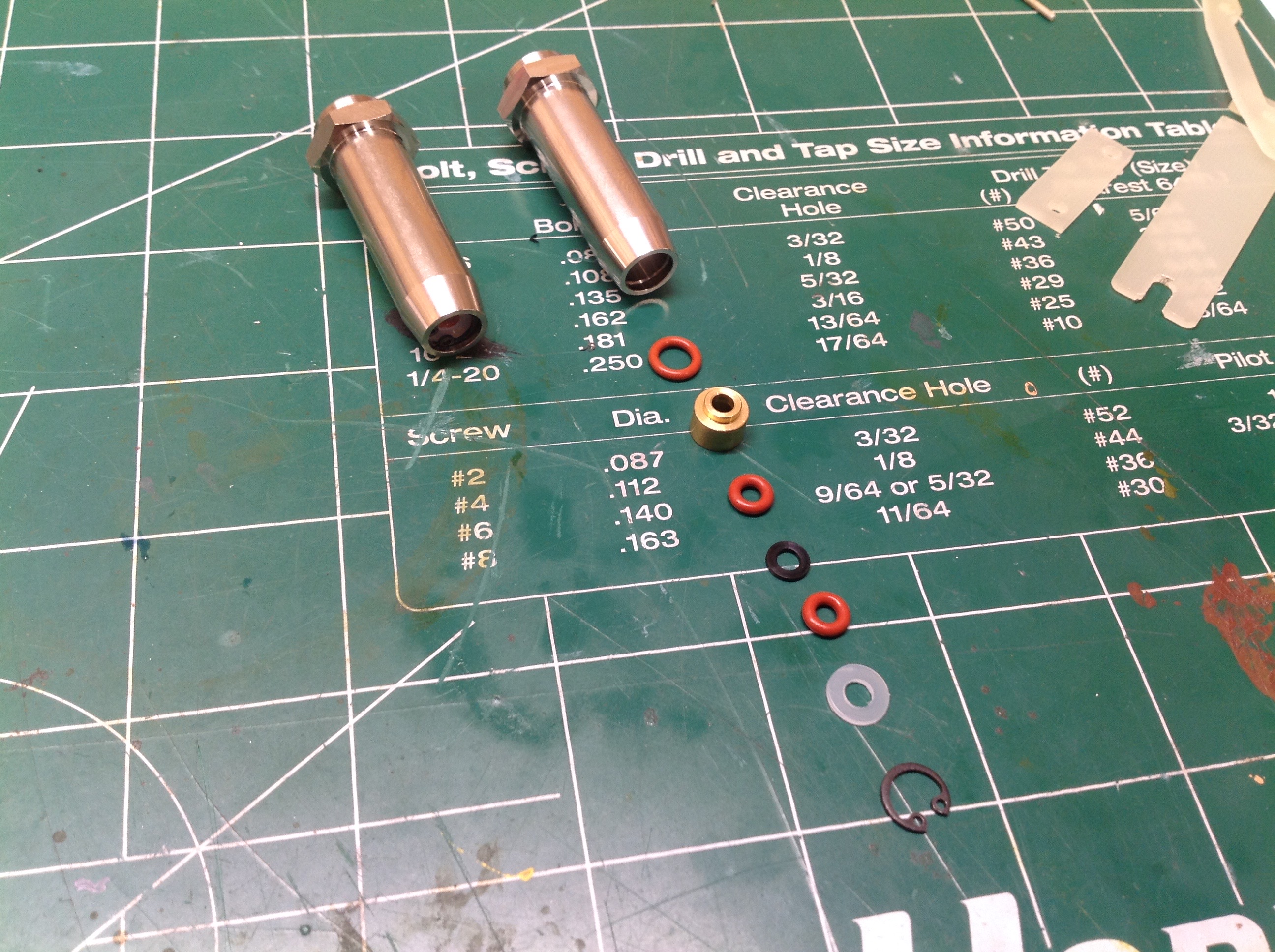
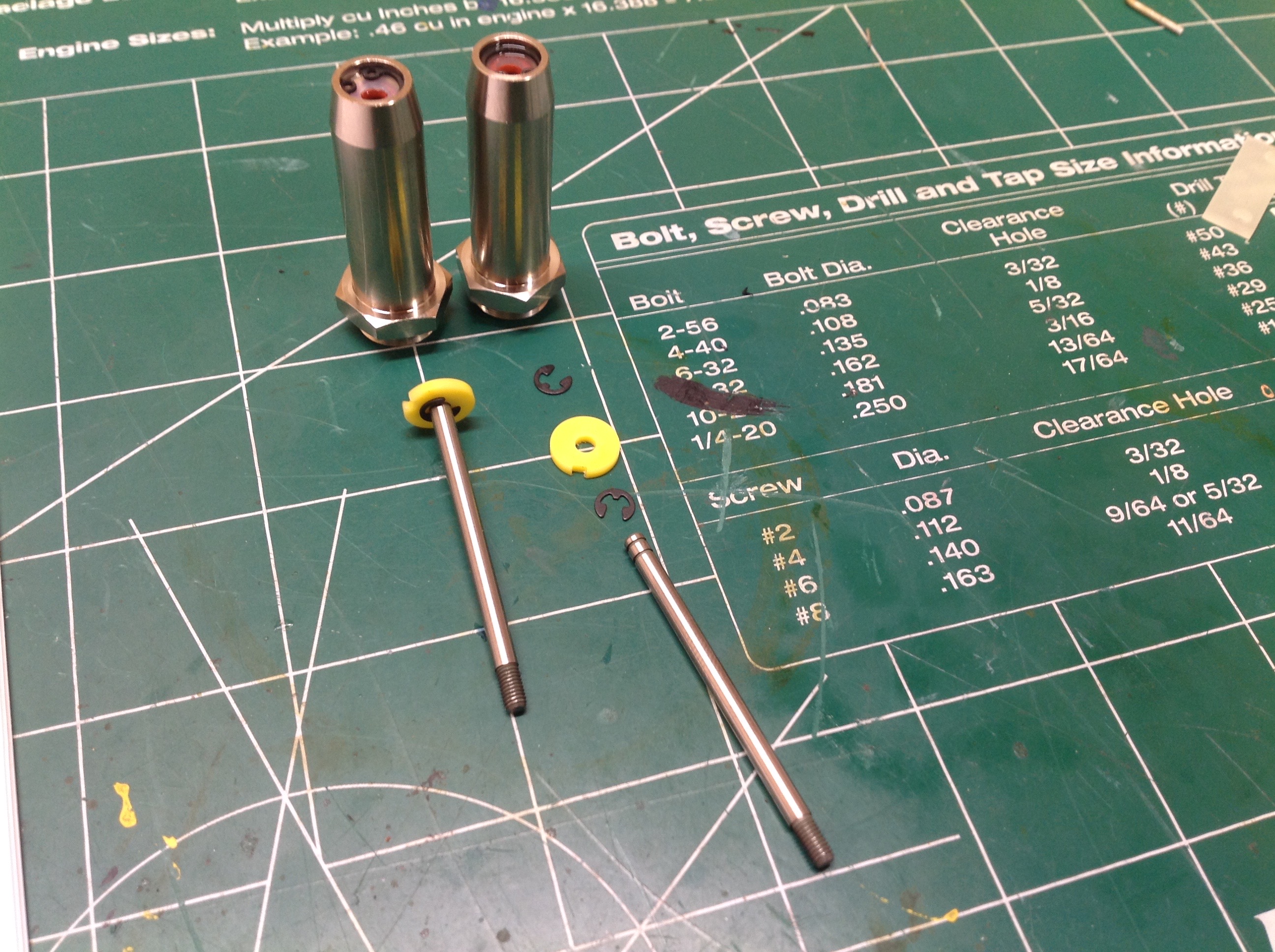
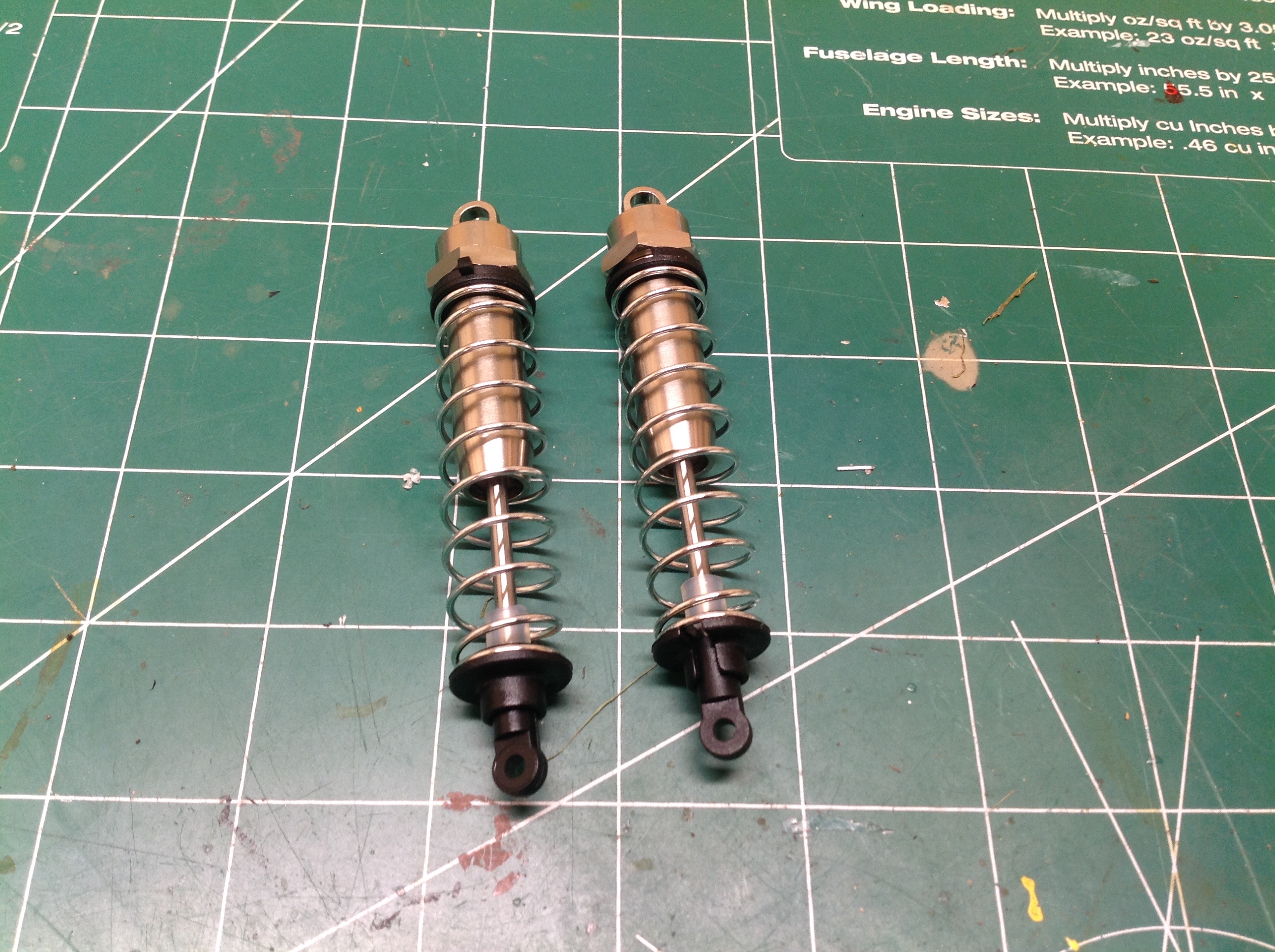
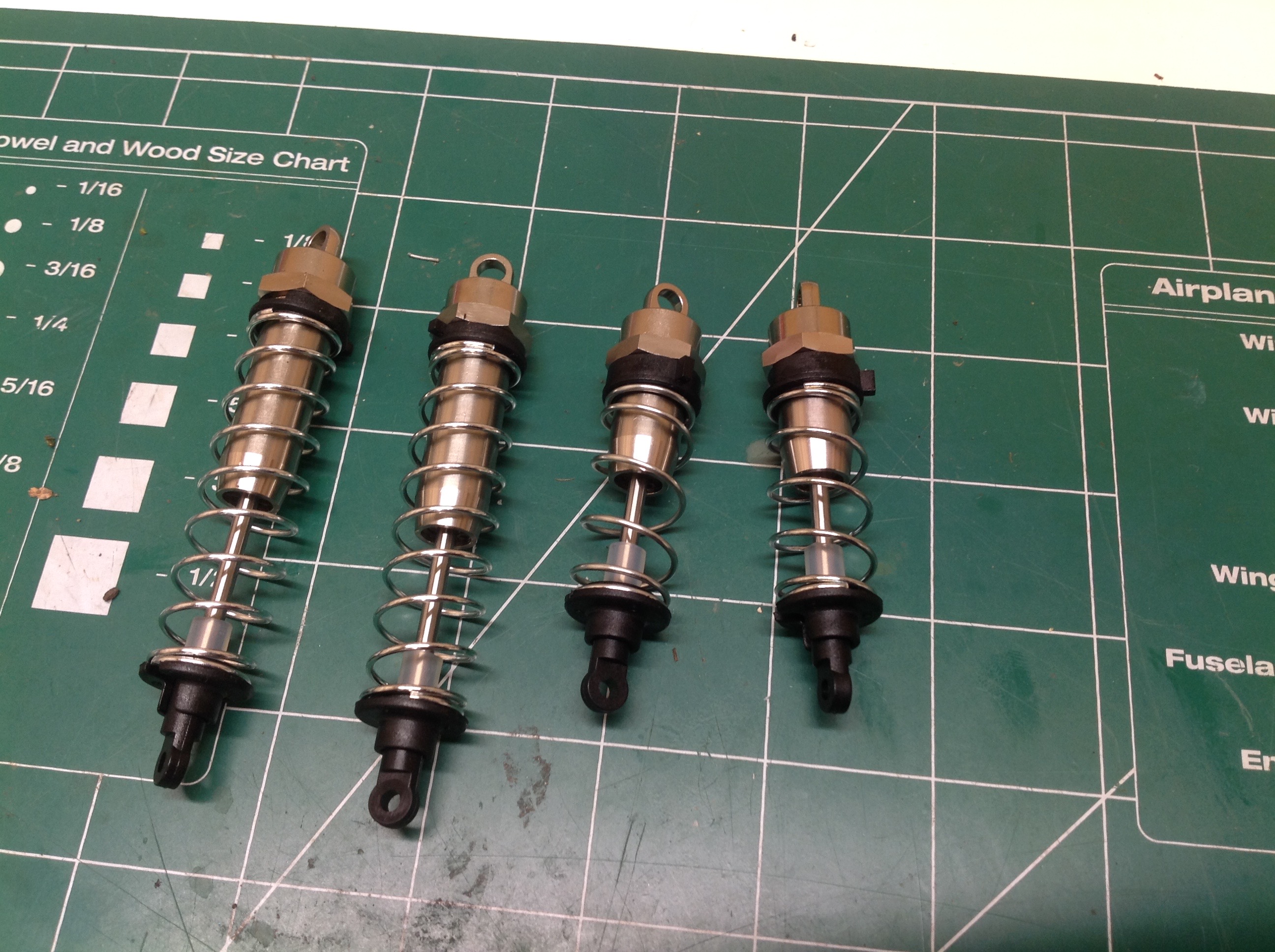
Time for the beautiful shocks. Each machined aluminum cylinder
gets a whole series of o-rings. The first and largest o-ring sits
ahead of the brass gland. The gland provides lateral support to
the rod. Then there are two smaller red o-rings with a black
spacer in between. Finally there is a Delrin scraper. There
are no threads (which consume precious stroke) here, instead the whole
thing is retained with a tiny C-clip. Good luck installing
this. I don't have any C-clip pliers remotely small enough so I
had to grind the tips on a pliers to make something work. Then the
piston heads are installed with E-clips as shown on the right.
Once the rods are installed the rod end is threaded on and then the
shock is filled with oil. The springs and spring perches are
last. The front and rear shocks are different lengths and also use
different oil weights by default.
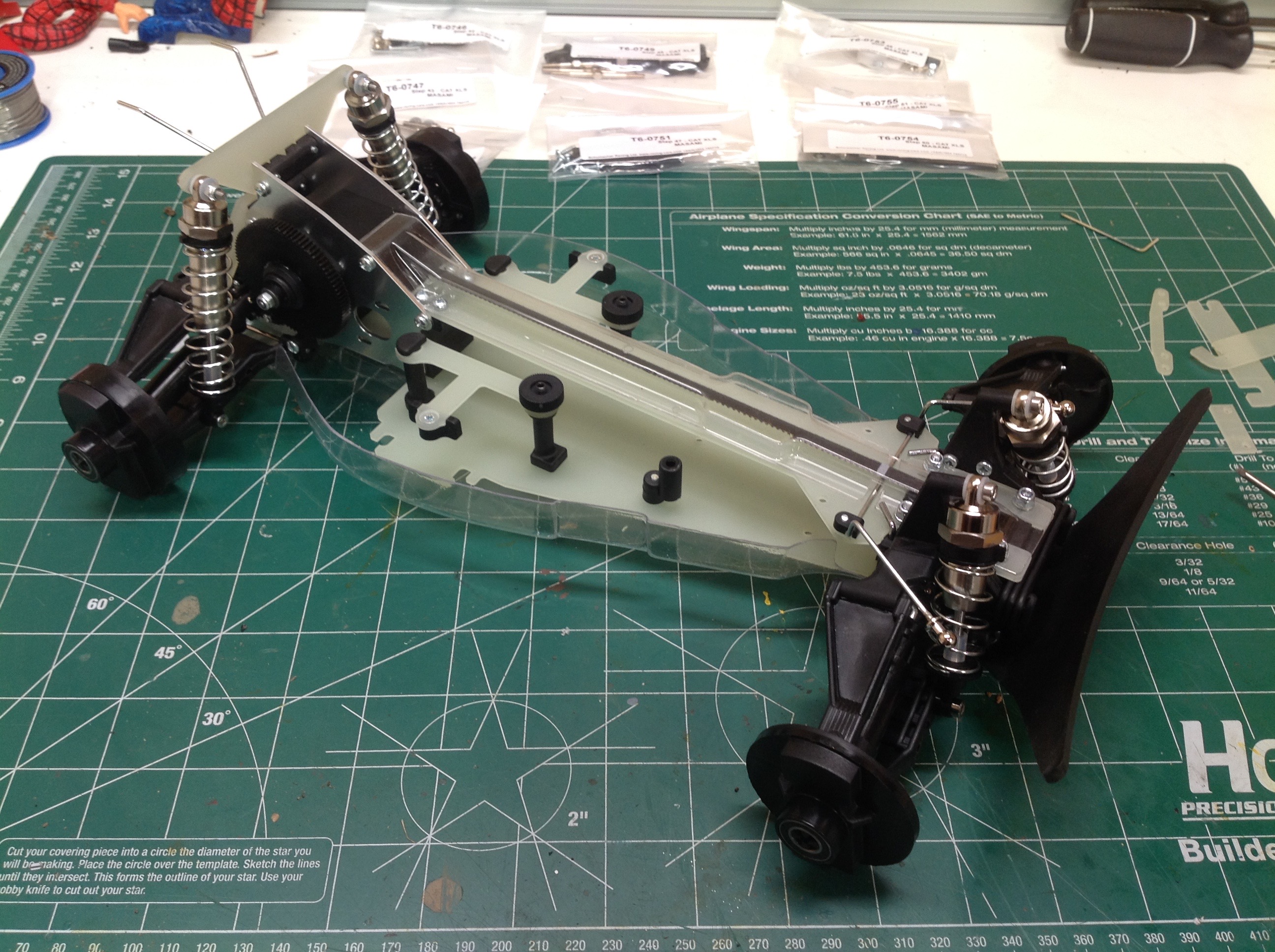
With the shocks installed this looks almost like a rolling chassis. However, the steering has still not been built.
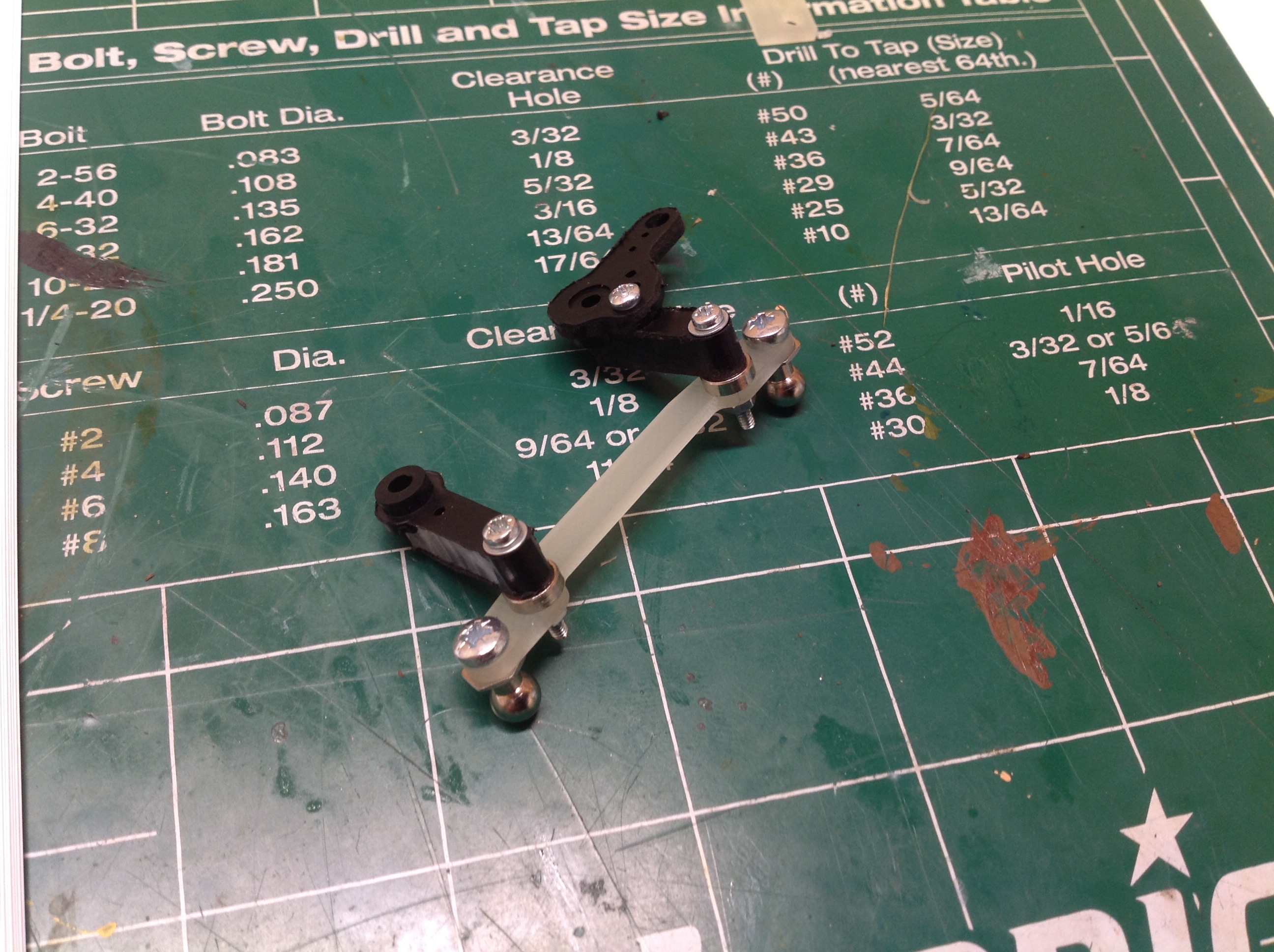
The dual bellcranks for the steering come next, and installing them is
the hardest step in the whole model. The screws must go in from
below and there is simply no access. The instructions should be
changed to perform this step much sooner. I also had to trim away
quite a bit of the undertray to make room for the steering system
motion.
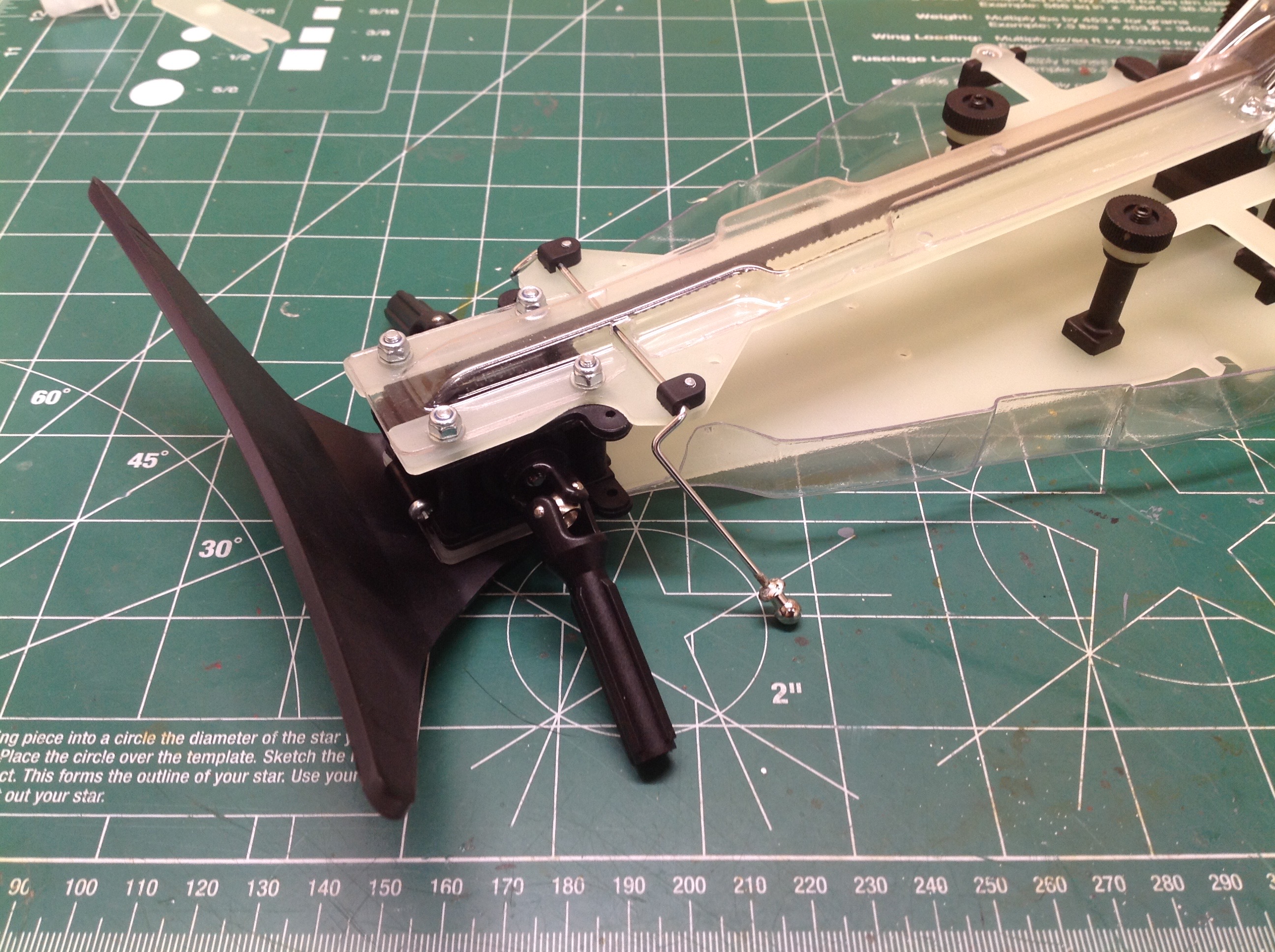
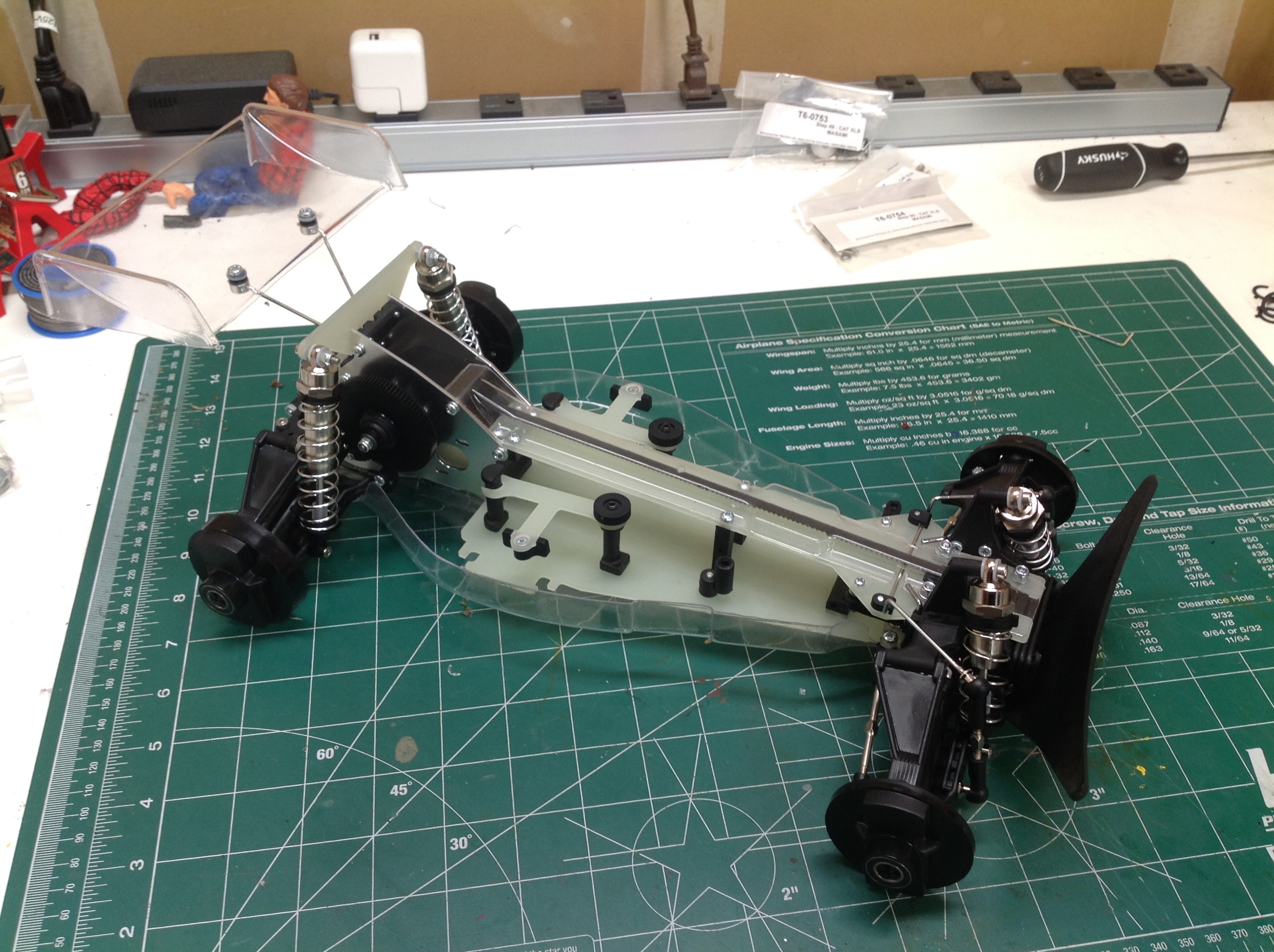
With the steering cranks finally installed it is time to attach the tie
rods and the push rods for the sway bar. These all use
turnbuckles. Once that is done, the rolling chassis is finally
complete. The last step is to trim and attach the wing.
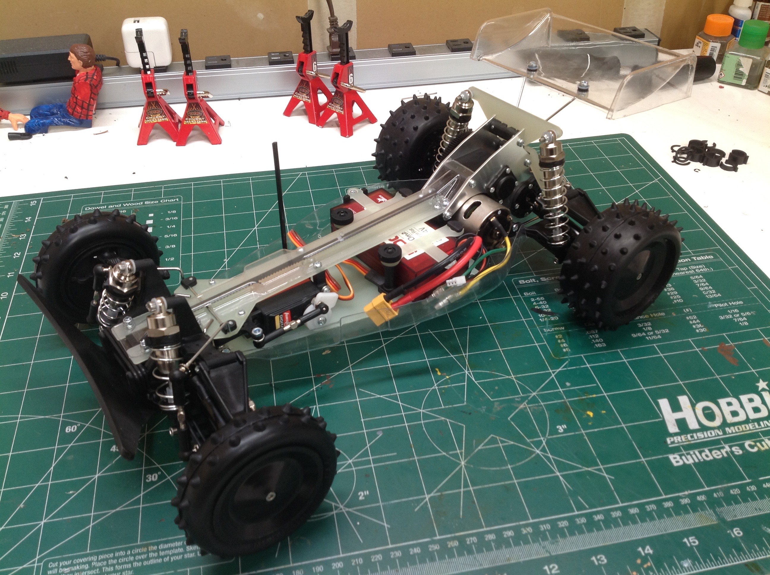
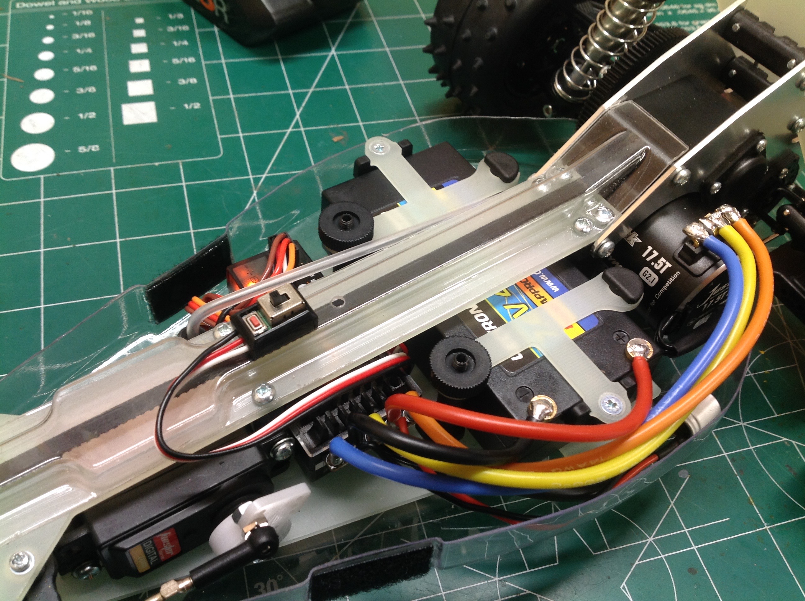
Now it is time to install the electronics. At the time of my
initial build on the left I did not have a motor yet so I just installed
a 540 silver can as a placeholder. I later installed the proper
Hobbywing 17.5T brushless and trimmed all the wires to fit as
shown. Brushless did not exist when this model was new, of course,
so the solder tabs on the motor interfere slightly with the body.
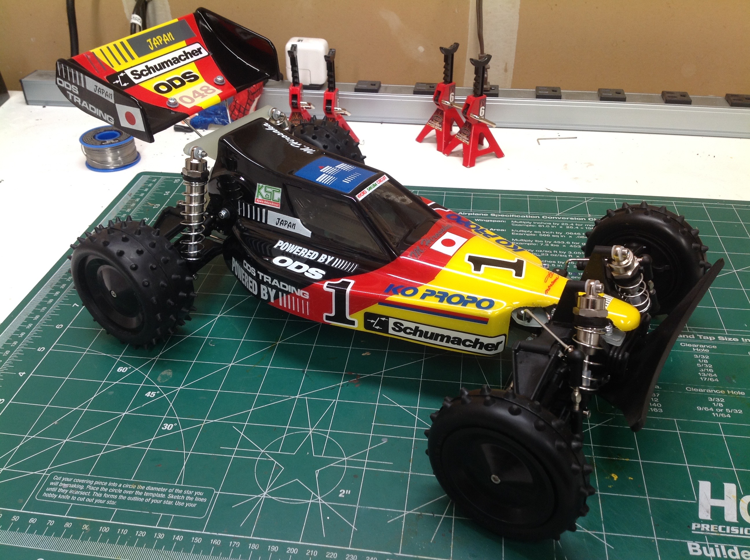
The final step is paint. There are no real instructions for this
so I masked to try to duplicate the box art and I think I did a
reasonable job. I thought the colors on the wing were decals so I
painted the whole thing black but then discovered my error and had to go
back and paint the yellow and red on the outside. It came out
fine and I don't think anyone will know the difference. There is
no driver for this model so I tinted the windows with smoke paint.
©2019 Eric Albrecht