Toyota 4Runner Project
Page 1: Chassis Construction
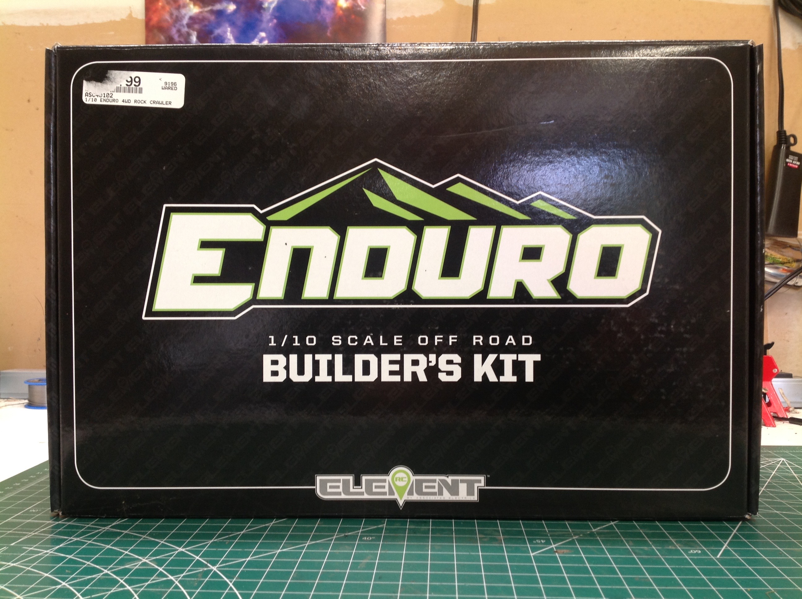
The Enduro chassis box is very modestly decorated on the outside with
only text and no graphics or pictures. This is in contrast to the
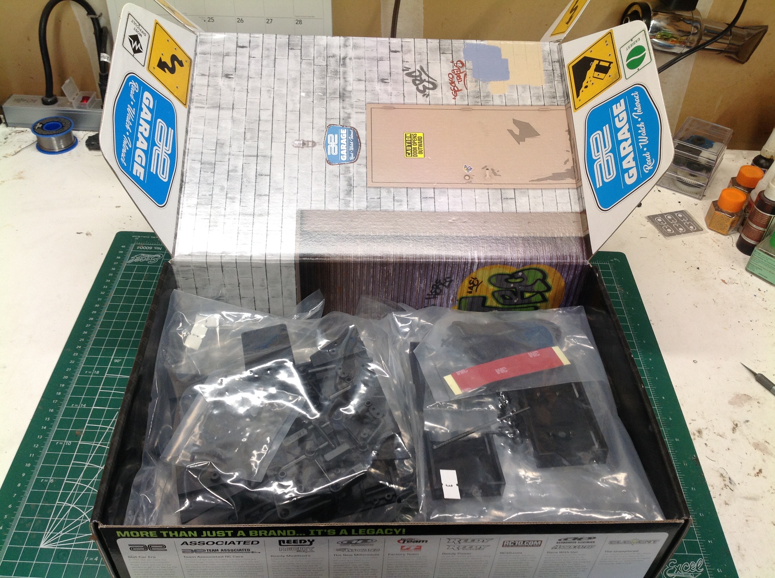
RTR box which is full of color pictures. The inside of the box, on
the other hand, features graphics of a scale garage which can be used
as a display for your truck. With no body or tires in the box, the
contents are just a series of bagged sequential plastic parts and
hardware which don't look like much.
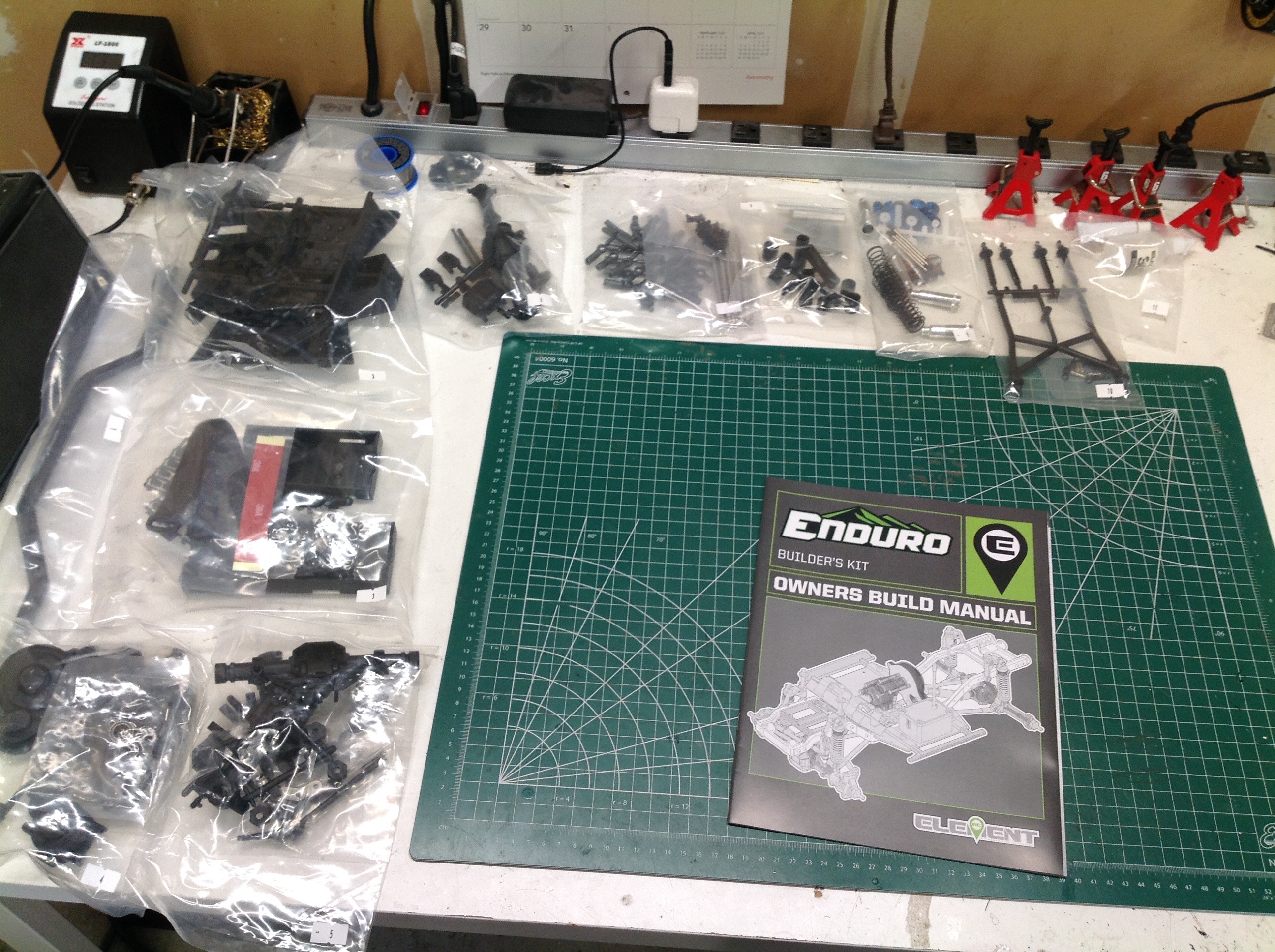
Here are the contents laid out on my table ready for building.
Each bag contains the parts for a series of steps, grouped in logical
subassemblies. The manual is black and white shaded drawings which
are very clear.
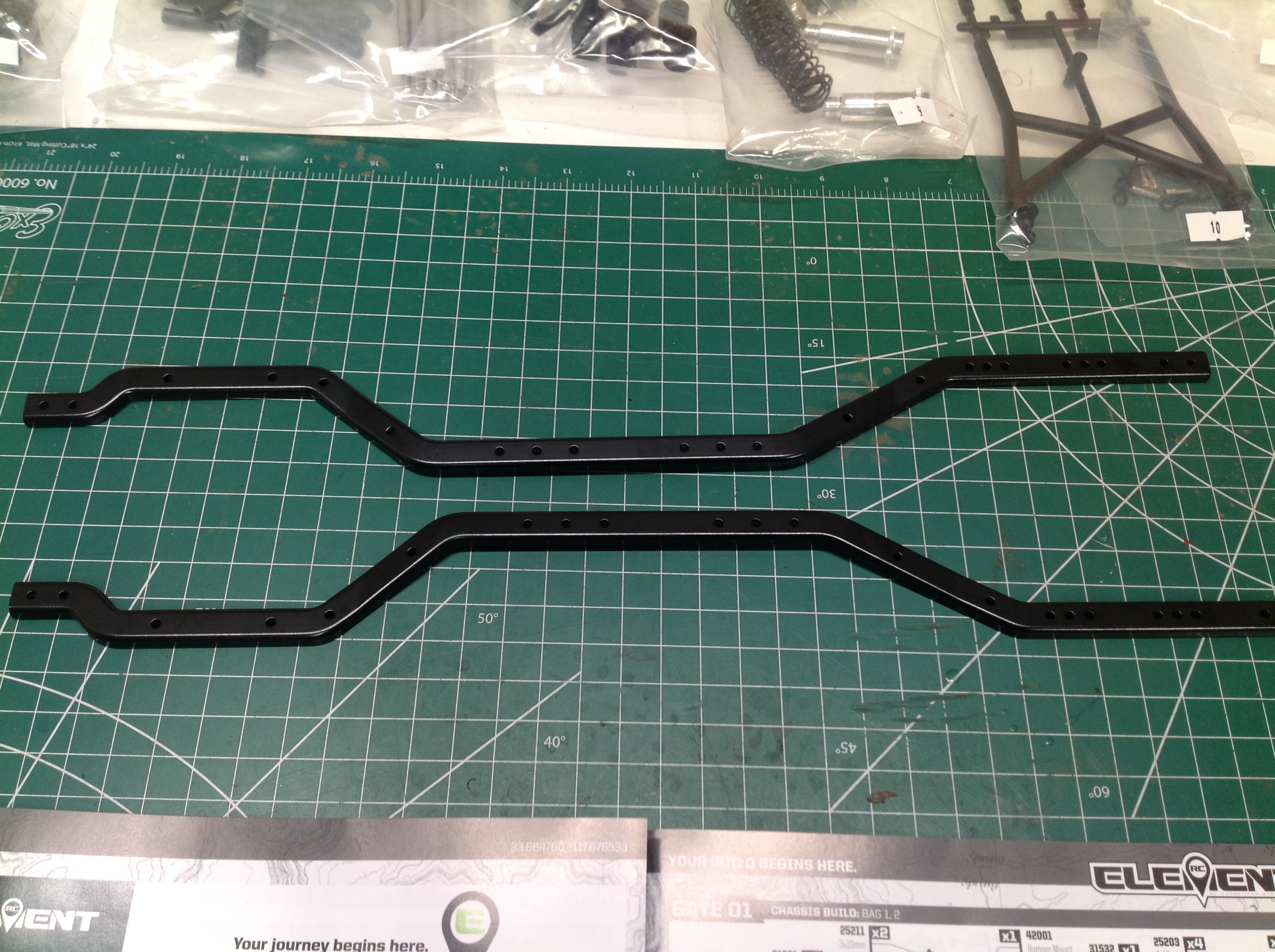
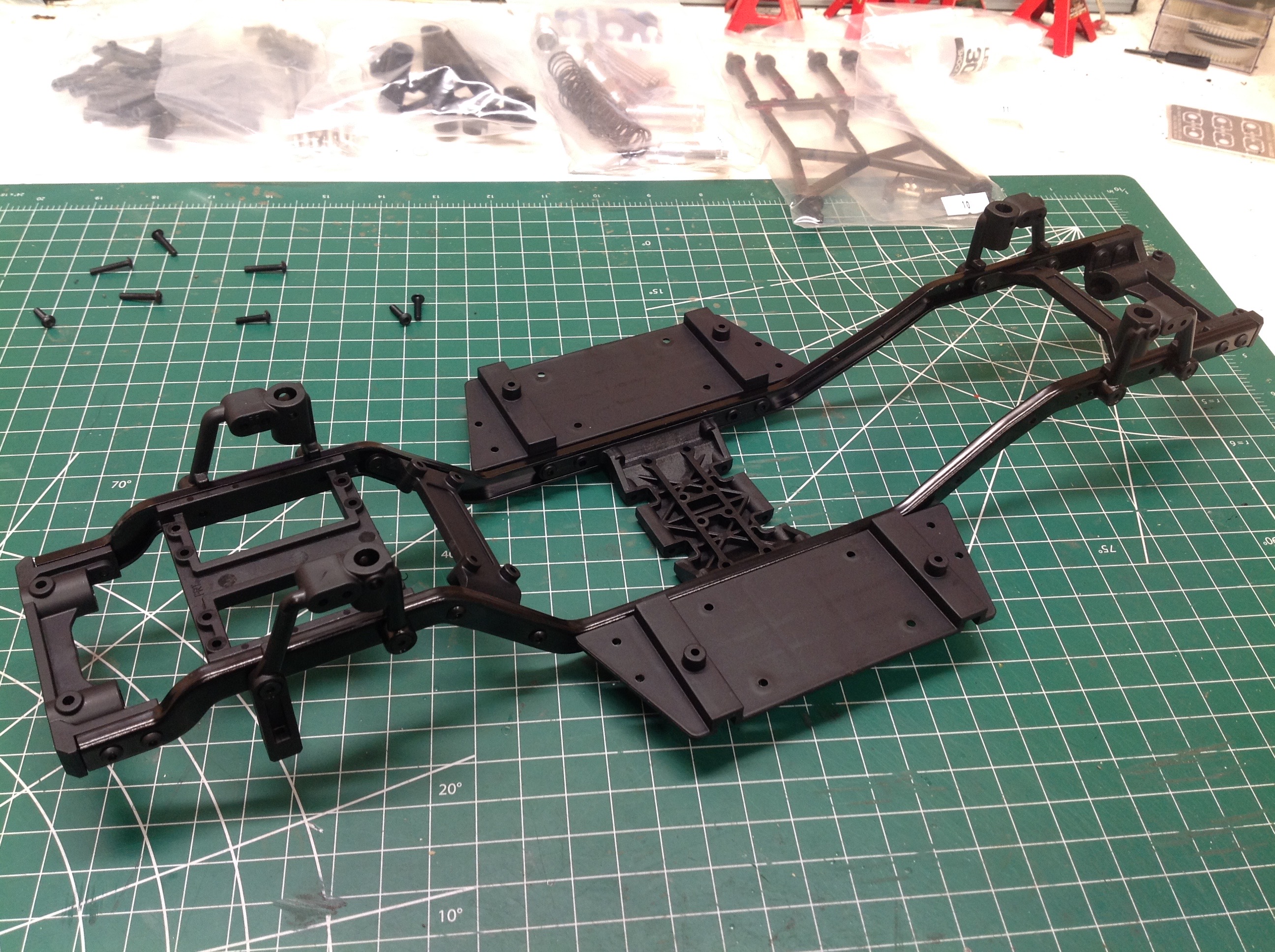
The build begins with the ladder frame chassis and the formed steel
chassis rails. These are assembled with a series of plastic cross
members and skid plate as shown on the right. You can see that the
skid plate is heavily reinforced. All of the plastics in this kit
are black, but stronger versions of everything are available in a gray
plastic. I can't really imagine breaking any of these parts so
I've left them alone. The shock towers and floor boards have also
been installed.
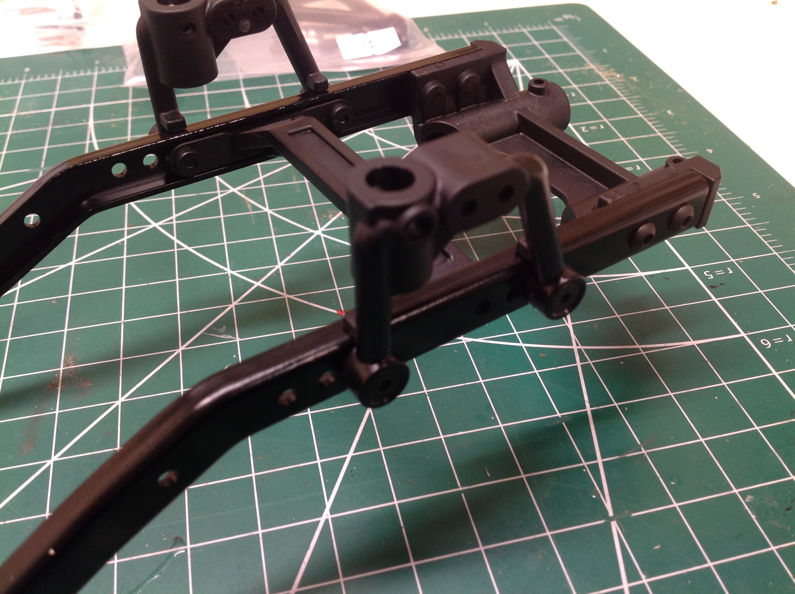
This close-up of the front shock towers shows some of the adjustability
inherent in the model. The tower in installed in the forward most
of three sets of mounting holes. Moving it aft would reduce the
wheelbase. The shock tower itself also has two holes to choose
from for mounting the upper end of the front damper. The towers
can also be swapped left to right to change the relative position of the
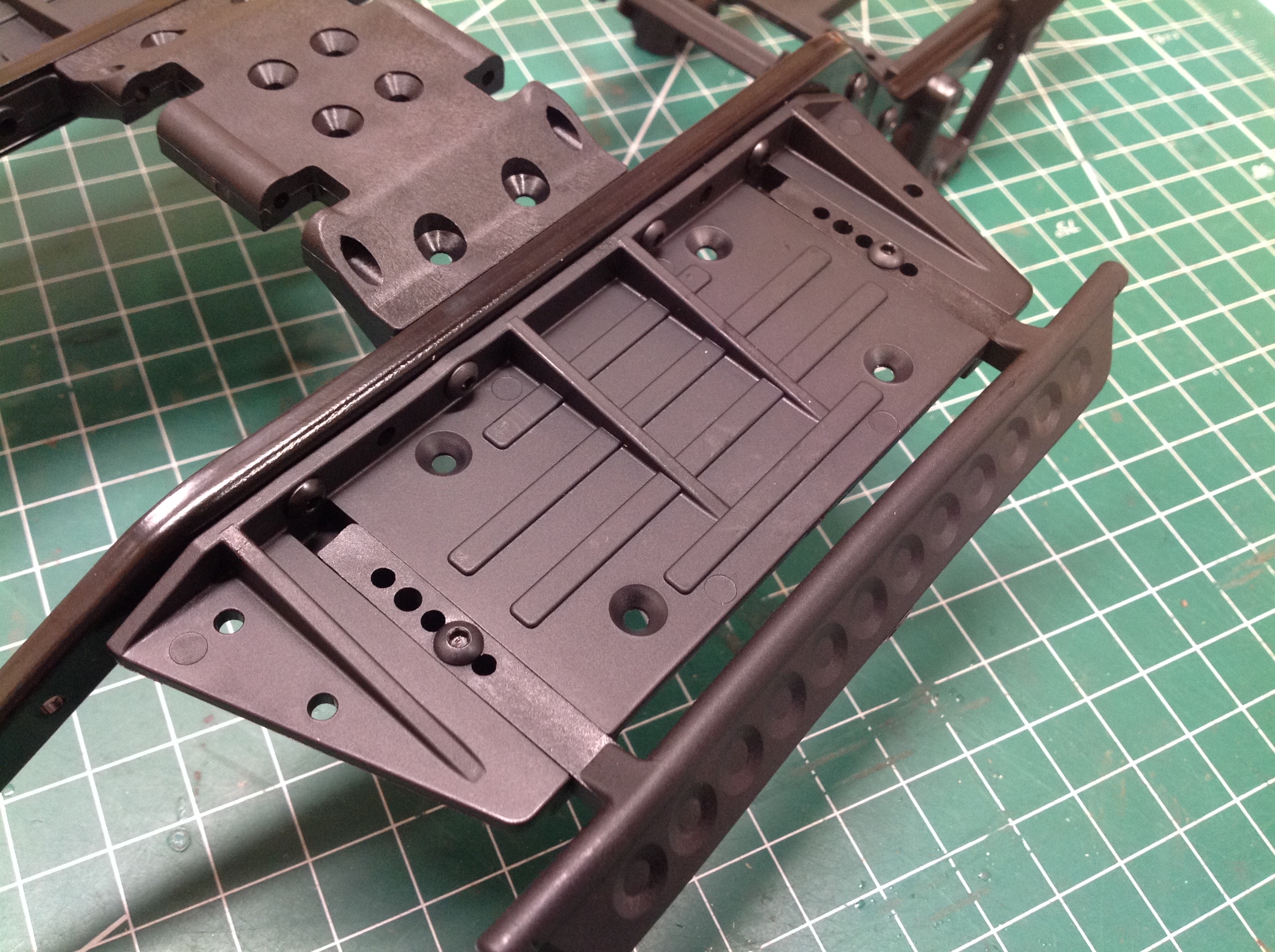
body post holes. The right hand image shows the adjustability in
the rock sliders from below.
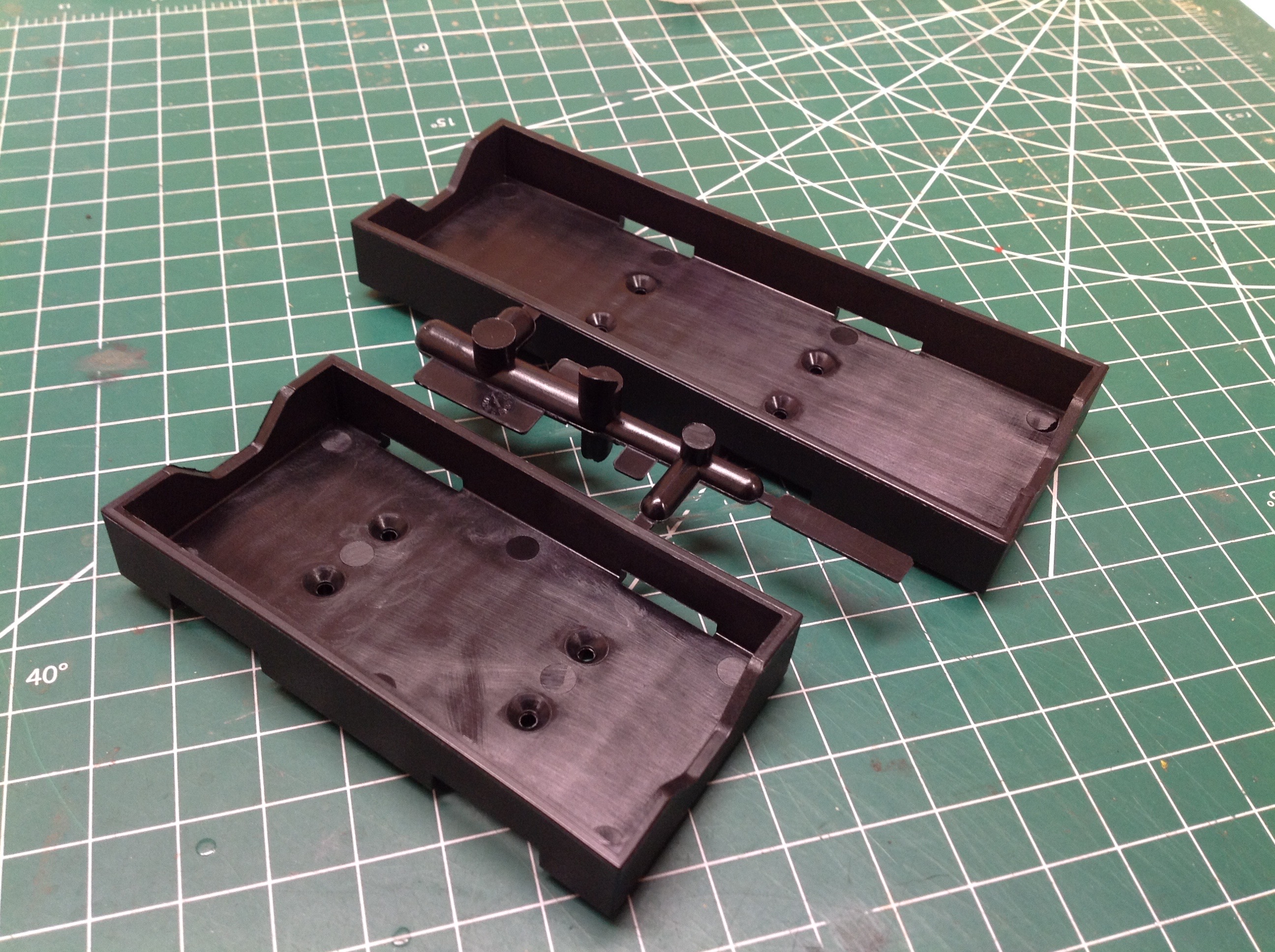
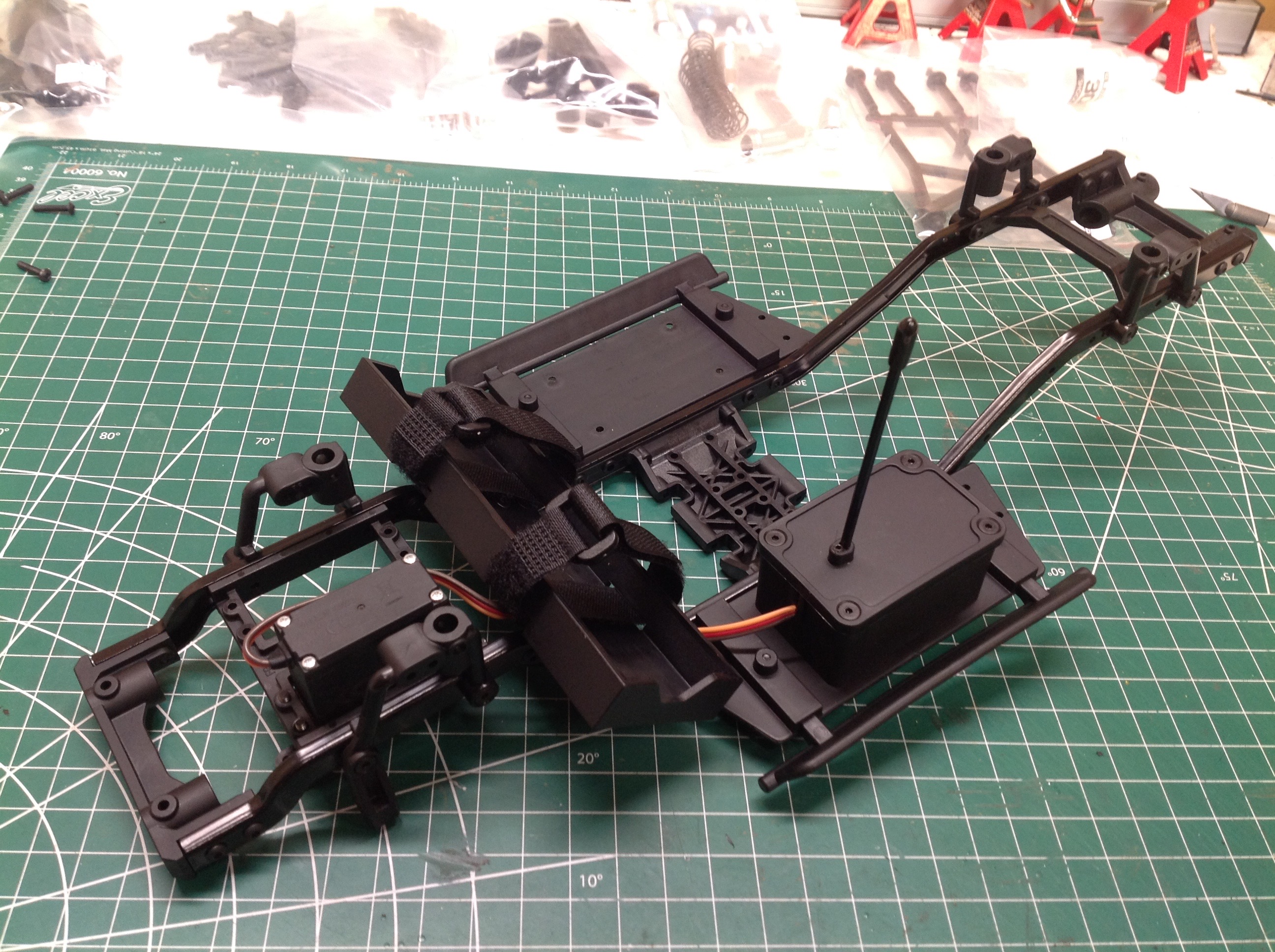
The kit comes with two battery boxes, one for a standard sized battery
and one for a shorty pack. I chose the larger option and attached
it to the forward cross member as shown. At this point the chassis mounted
steering servo and radio box have also been installed. The empty
spot next to the steering servo is for an optional servo winch.
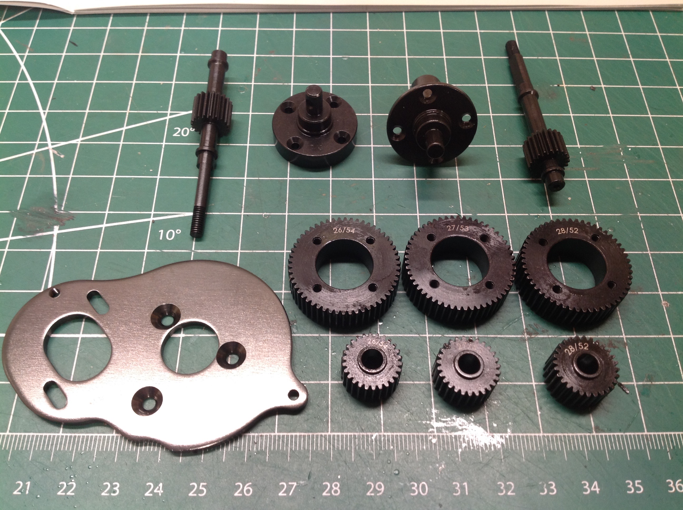
The "Stealth X" transmission is one of the stars of this model.
The three pairs of huge steel gears shown represent optional
assemblies. Using the 52:28T gear pair results in an equal front
and rear axle speed (no overdrive). Using the 53:27T option (stock
per the manual) reduces the speed of the rear axle for a 5.7%
overdrive. Using the 54:26T option would be an even higher 11.8%
overdrive. I used the middle set of gears for a factory 5.7%
overdrive. It is pretty impressive that the kit includes all three
optional sets of gears because these are certainly expensive parts to
just have sitting around extra. The entire transmission can also
be built to have the motor facing either forward or backward. I'm
not sure what difference it makes other than balance or to allow room
for a vehicle interior. I used the standard forward facing option.
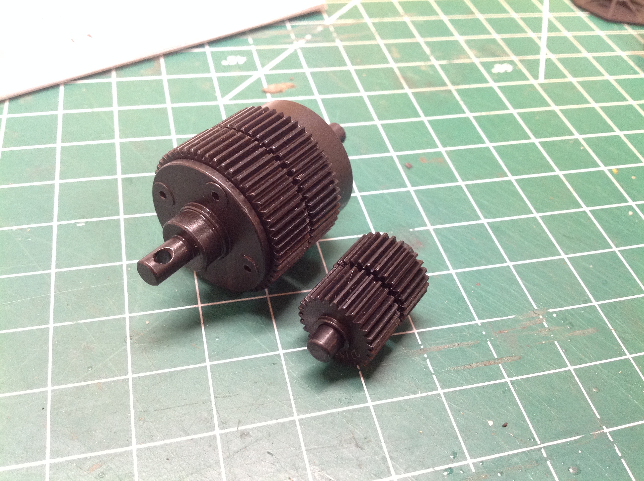
Here are the output shaft (large gears) and counter shaft (small gears)
assemblies. You can see the very slight difference (1 tooth) in
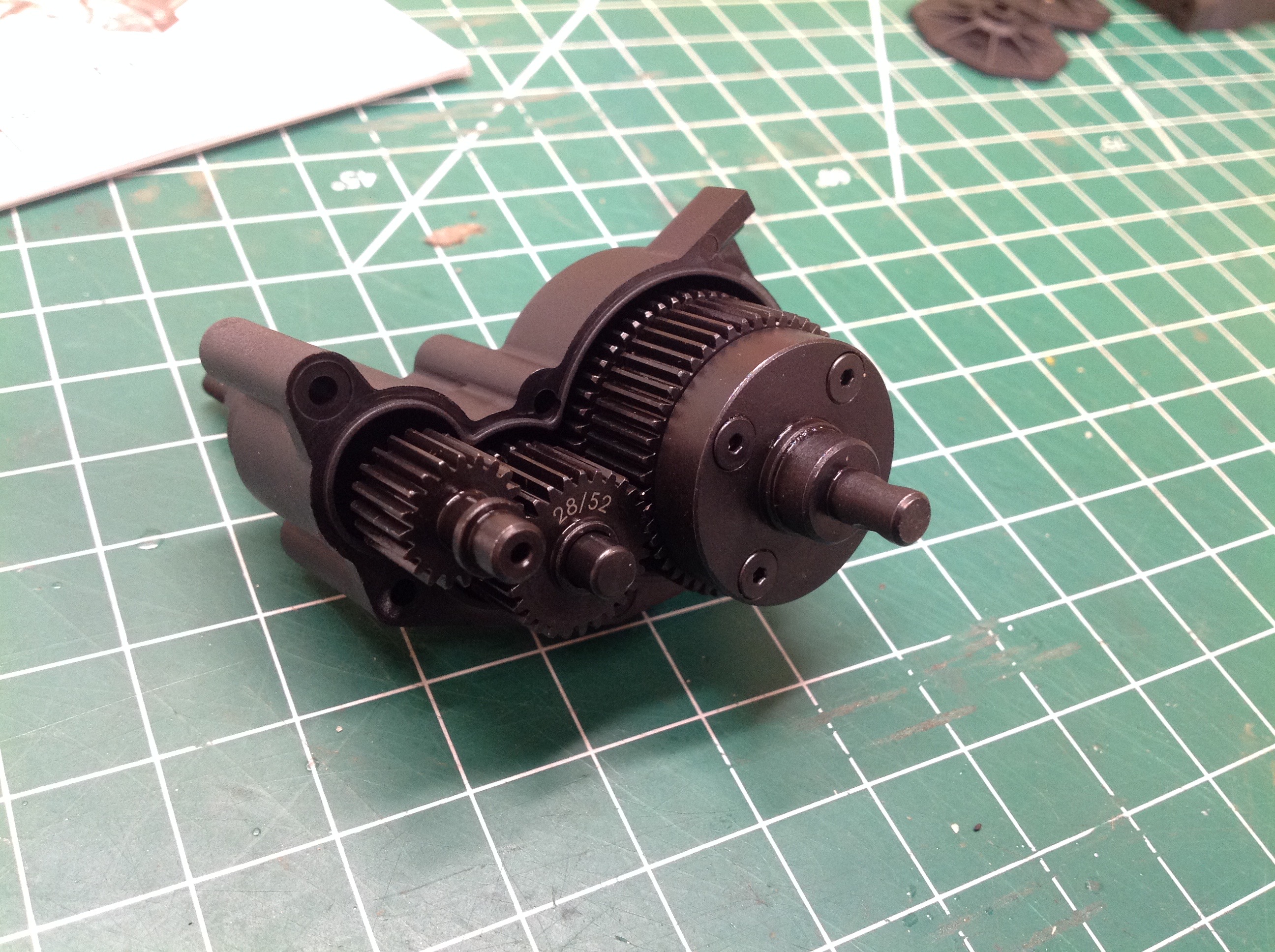
size between the front and rear gears. On the right, you can see
these assemblies installed into the gearbox housing along with the 20T
input shaft. The input gear drives the front counter shaft gear
directly. Both front and rear gears are locked to the counter
shaft so they rotate at the same speed. On the output shaft, on
the other hand, the two gears are on the same axis but there are
bearings between them allowing them to rotate at different speeds.
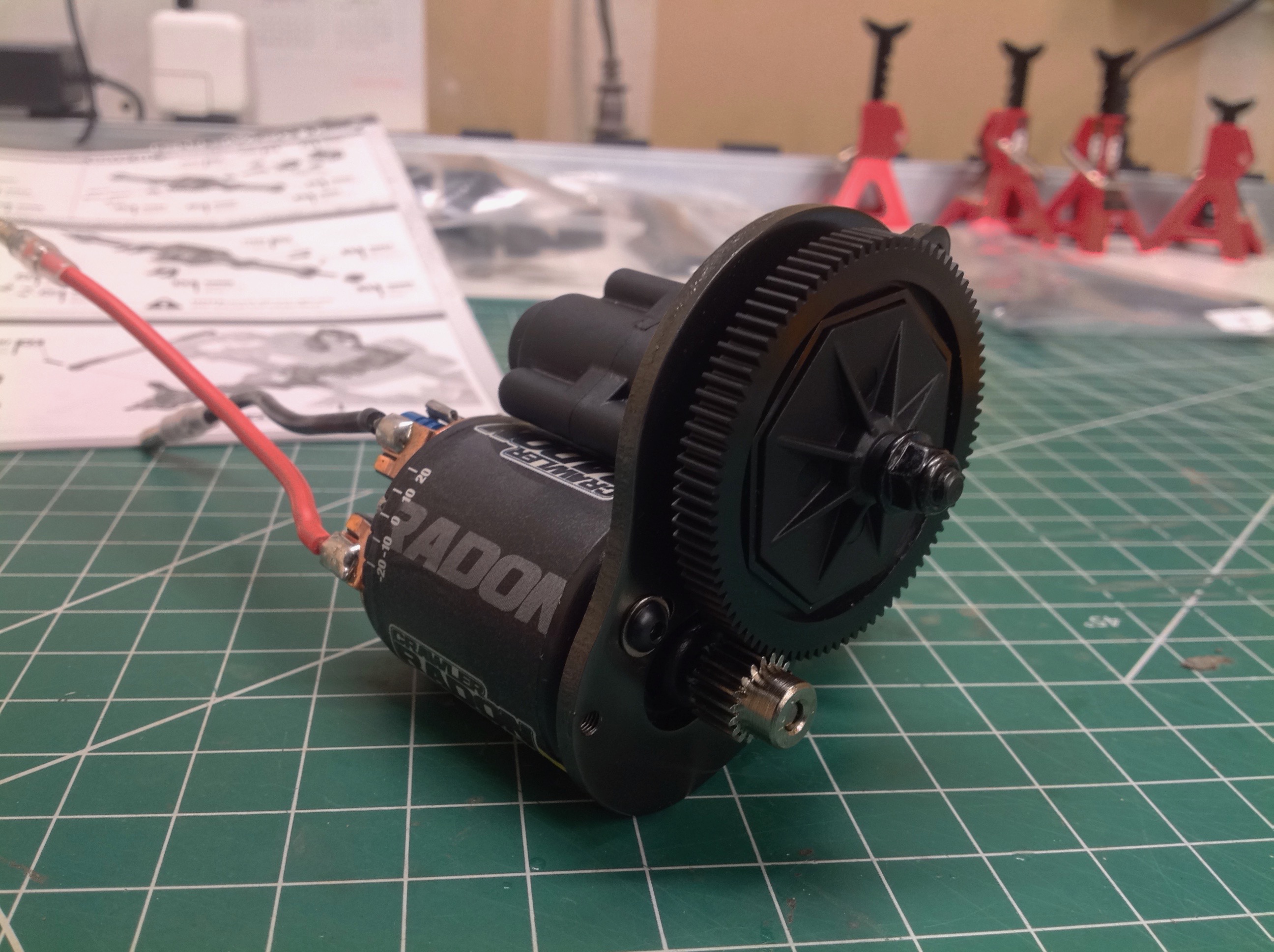
The input shaft is connected directly to the 87T spur gear through what
looks like, but isn't, a slipper clutch. Although clearly designed
to allow the use of a slipper clutch, there are no friction plates and
no clamping spring so the spur gear is locked to the shaft through the
plastic pads. Although it can't slip, passing the torque through
the plastic pads probably provides some cushion from the forces
associated with dynamic impacts. I used a Reedy 5-slot, 20T
crawler motor to keep everything in the Team Associated family.
The kit doesn't come with a pinion gear but recommends an 18T 48p gear
so that's what I used. Steel of course. Transmission ratios
are therefore:
- Front: 87:18 x 28:20 x 52:28 = 12.57:1
- Rear: 87:18 x 28:20 x 53:27 = 13.28:1
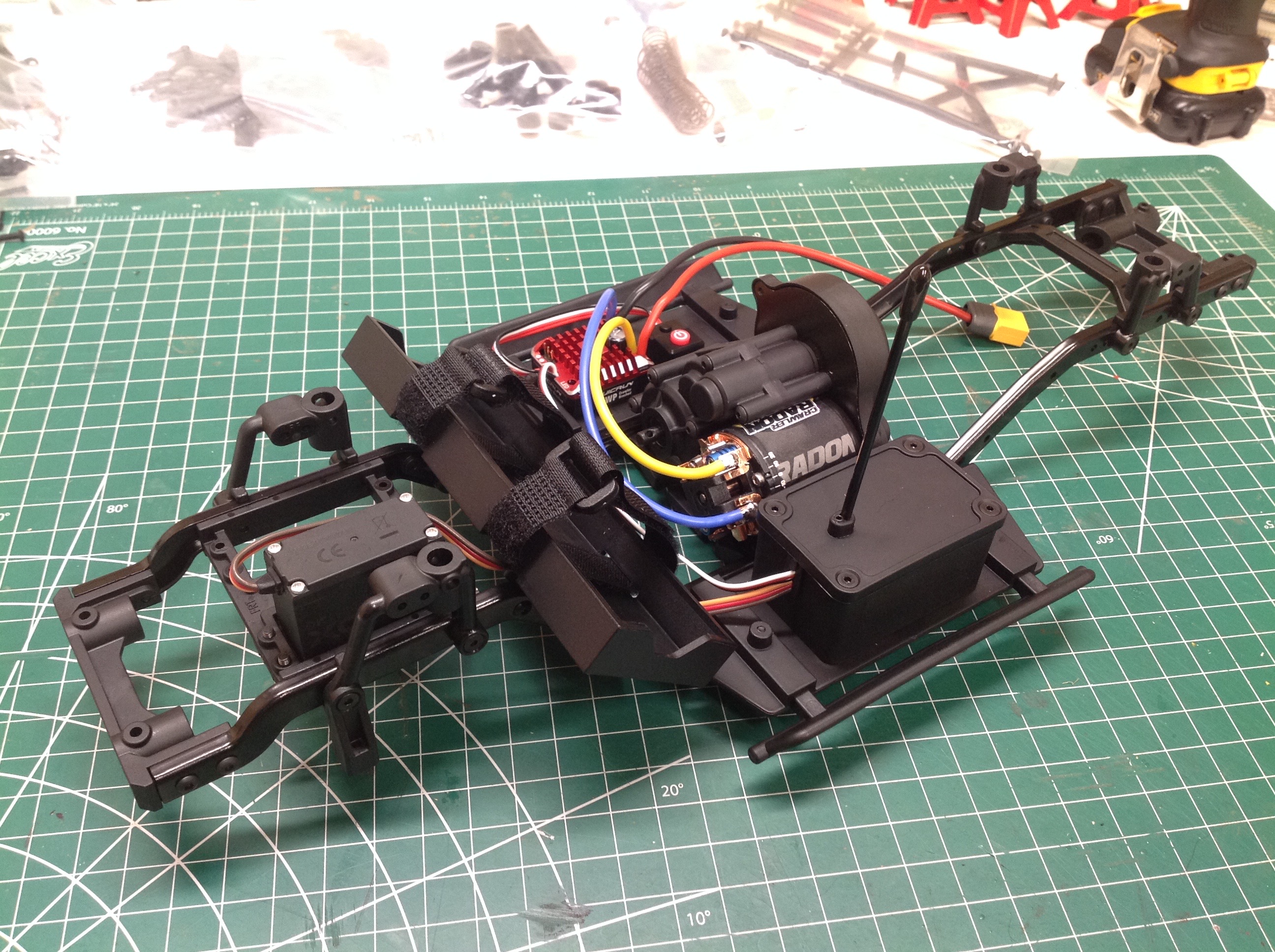
The right hand image shows the transmission installed onto the
chassis skid plate along with my Hobbywing 1080 crawler speed
controller. Many builds have the electronics installed last, so it
is interesting to see a kit which does all of this first. At this
point the electronics are completely functional so the model can be
powered up and tested. Of course, the outputs don't go anywhere
yet.
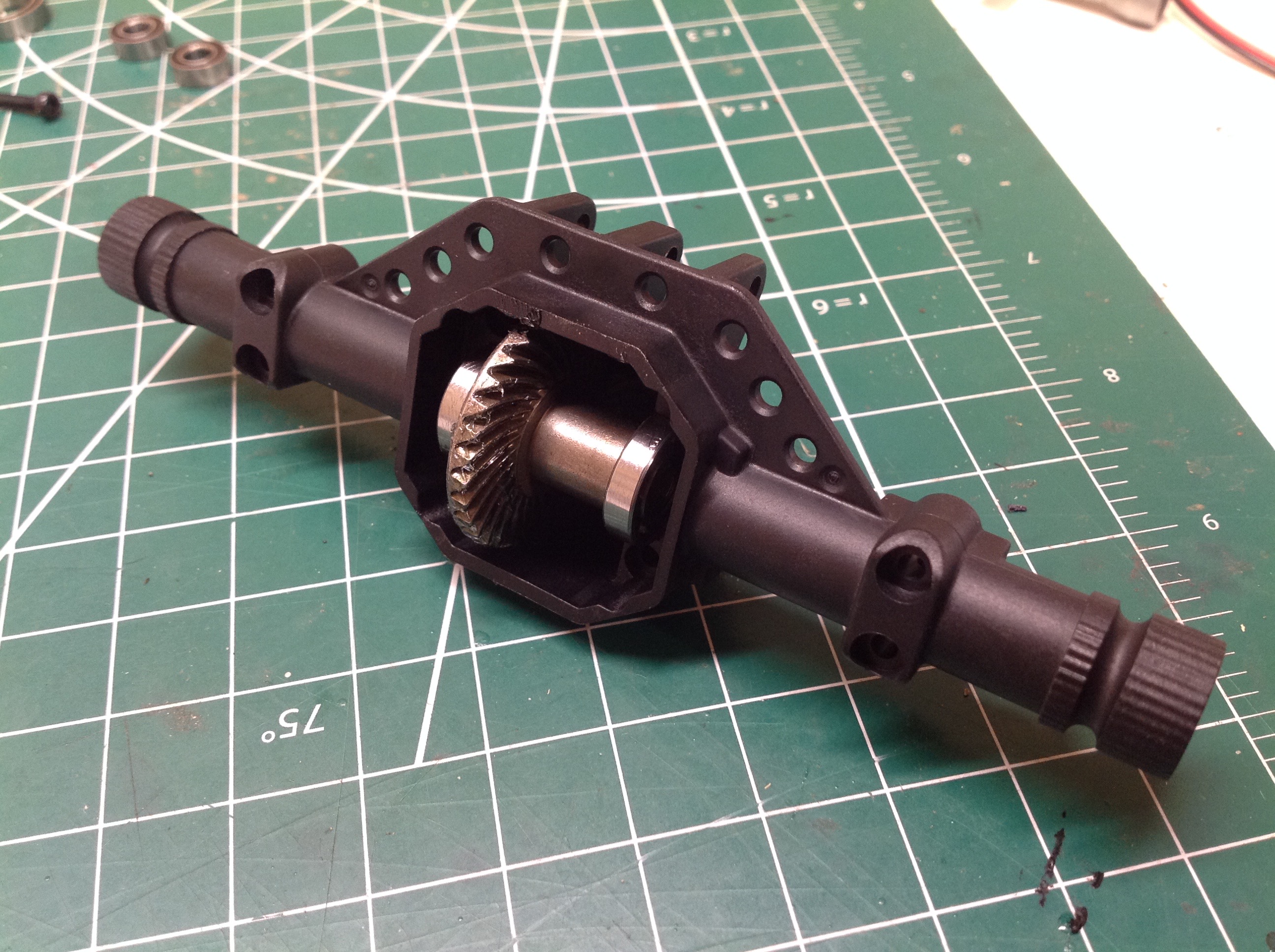
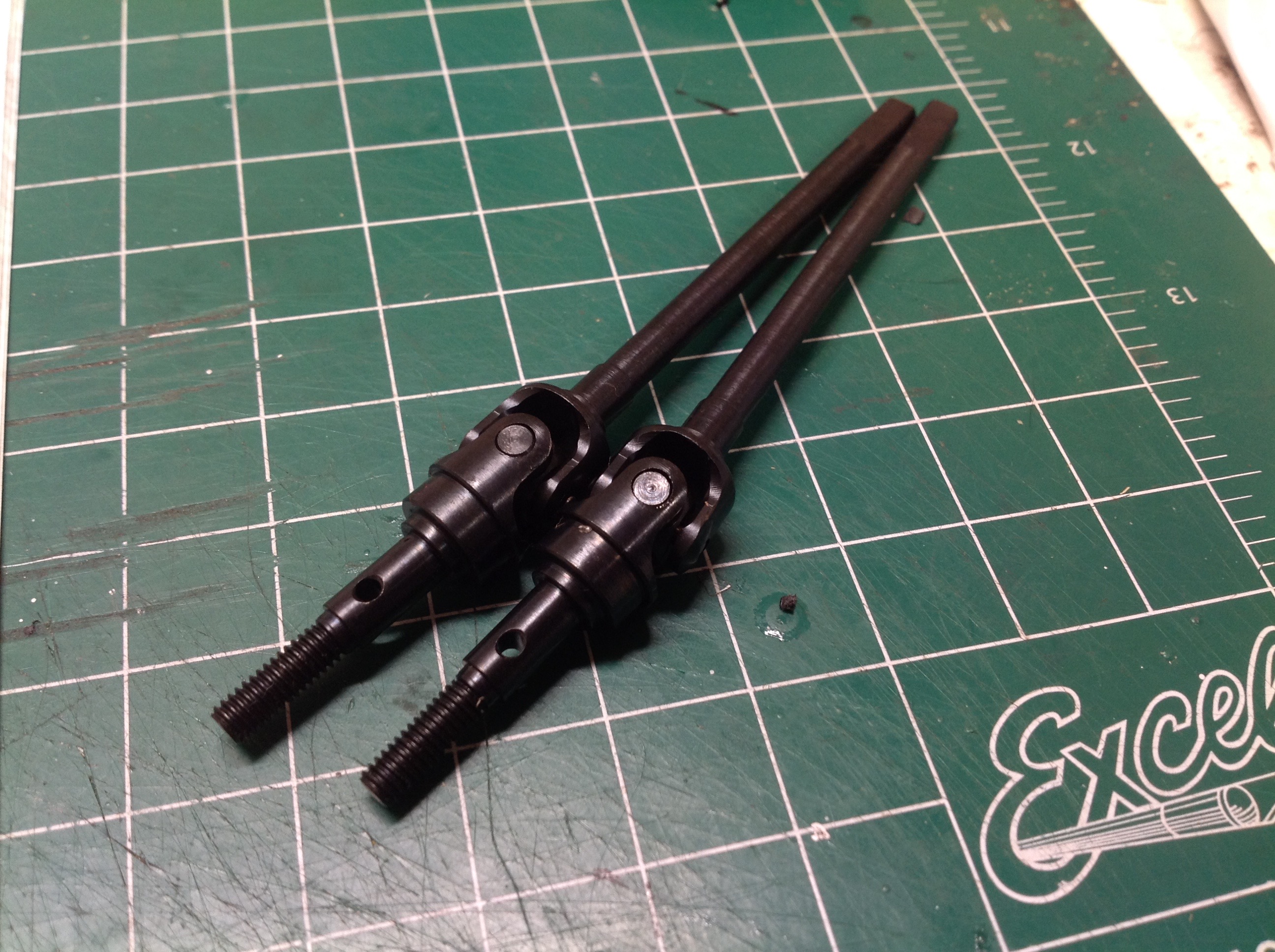
Now we can start on the axles, beginning with the more complex
front. The locker uses a spiral cut steel gear as shown on the
left, and the plastic axle housing has a very nice integrated overhead
stiffening brace. The axles are large diameter steel rods with
universal joints as shown on the right. The 30T ring and 8T pinion
result in an additional 3.75:1 reduction.
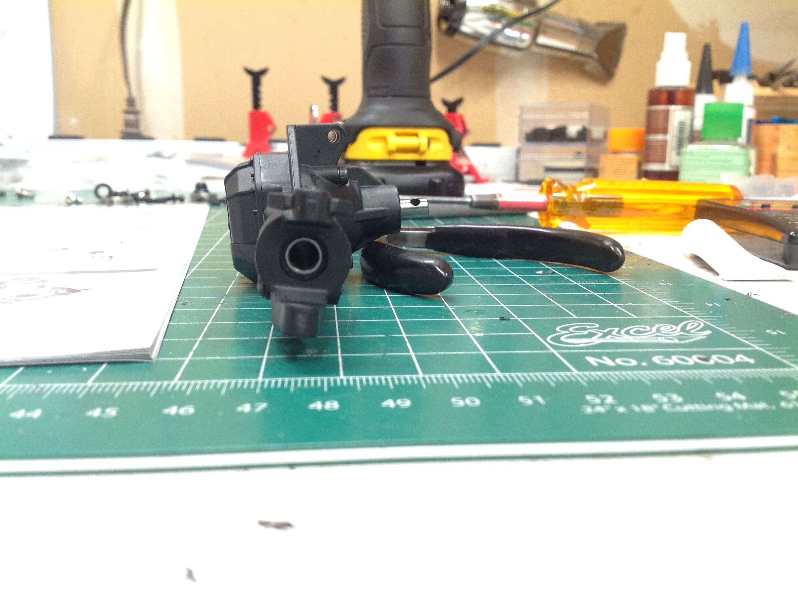
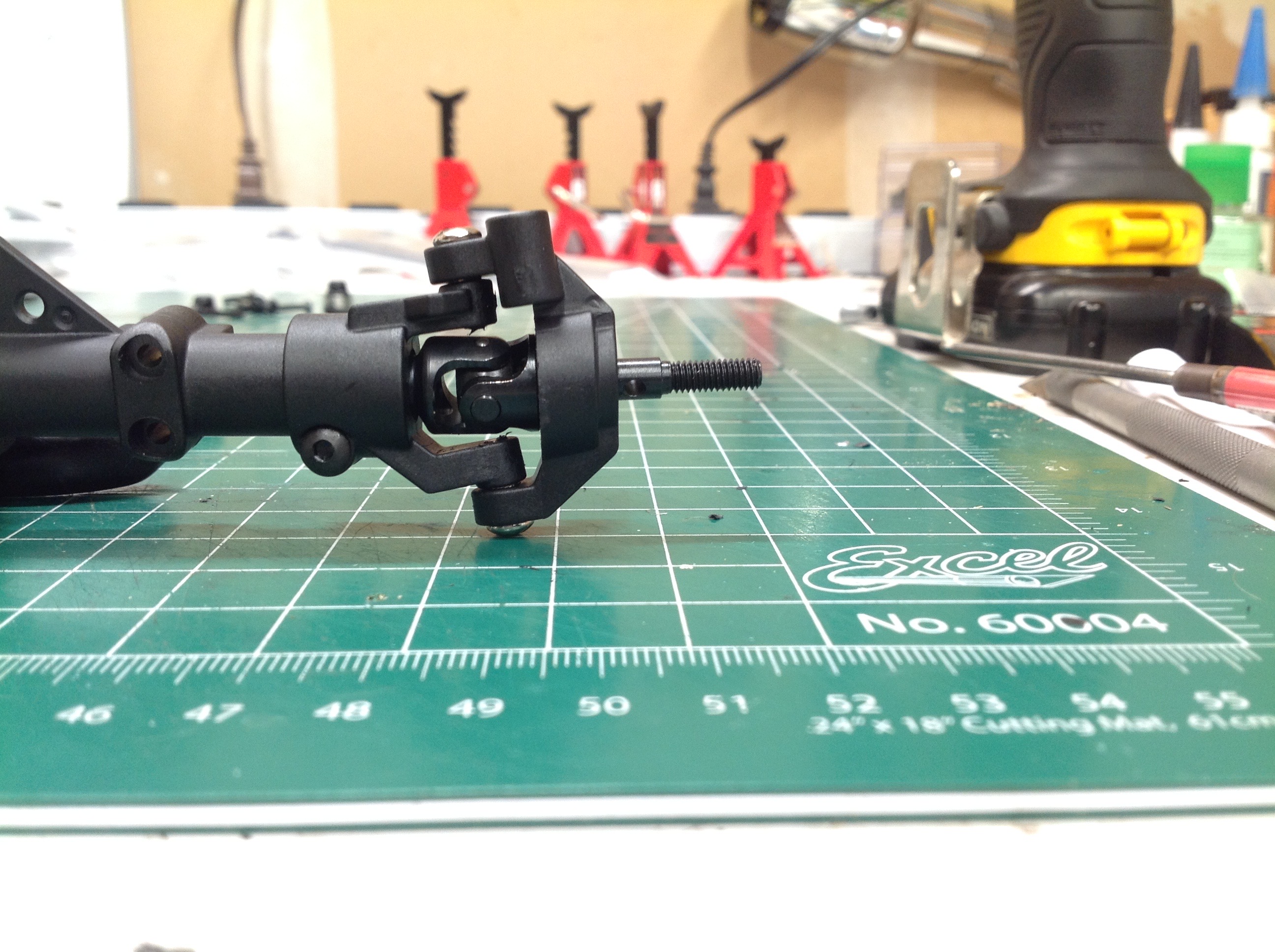
These pictures show some of the suspension geometry. The side view
picture on the left shows the caster angle. This can be adjusted
by rotating the caster block on the serrated axle housing. The
front view picture on the right shows the kingpin inclination.
Note that this does not result in a negative camber angle.
Instead, this makes the wheel rise slightly as a function of steering
angle which, in turn, makes straight ahead the most stable
position. Ideally, the steering axis should also intersect the
ground in the middle of the contact patch of the tire. This makes
the tire pivot in place when turning instead of swinging through an
arc. This would be a zero scrub radius.
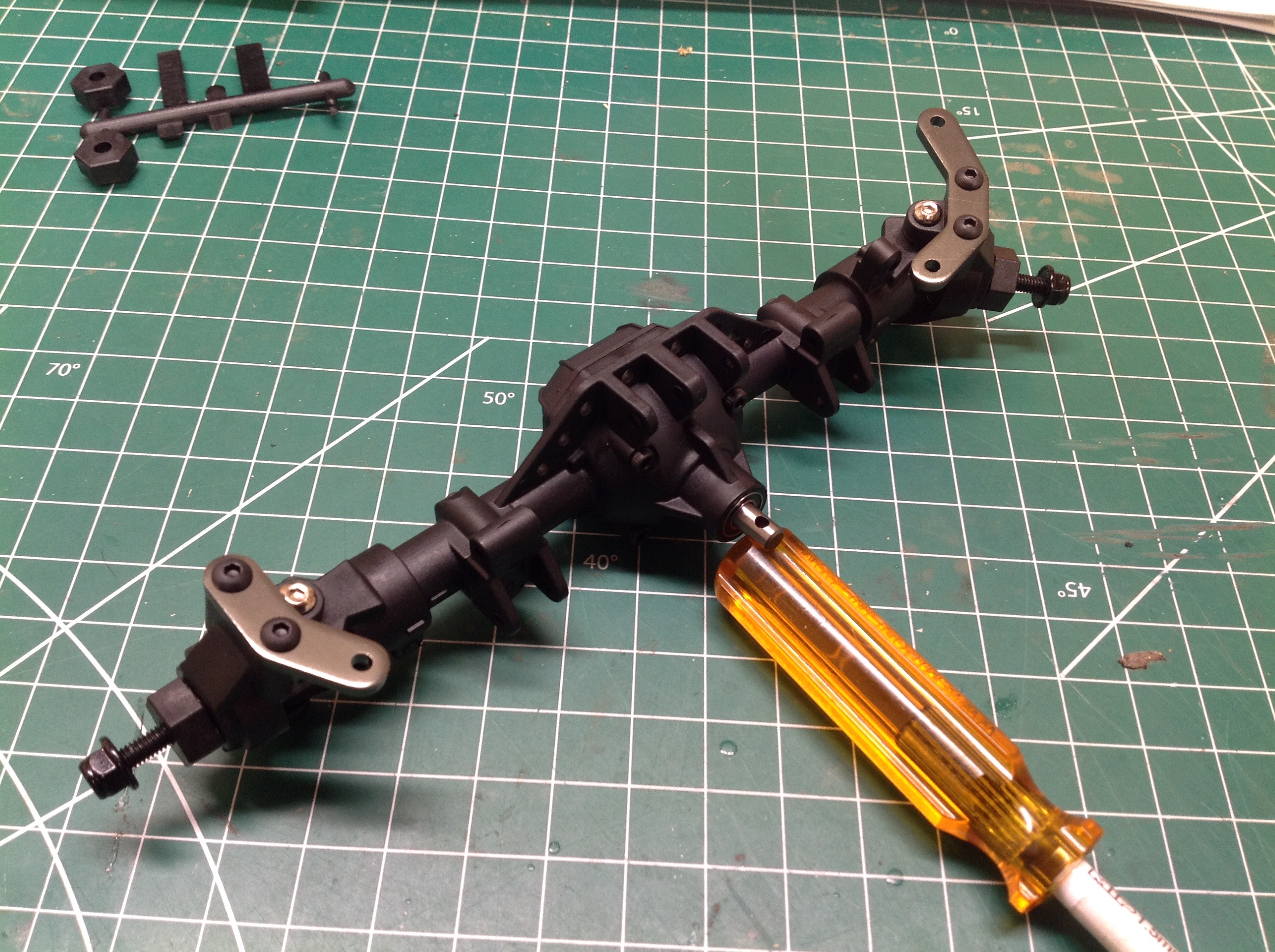
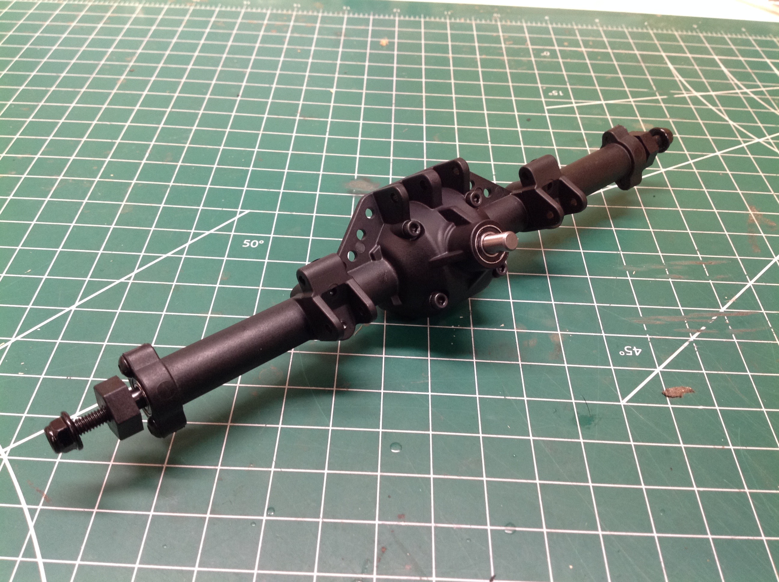
The left hand picture shows the completed front axle. The steering
cranks are separately installed aluminum plates. The rear axle on
the right is a simpler version of the front with straight axle shafts.
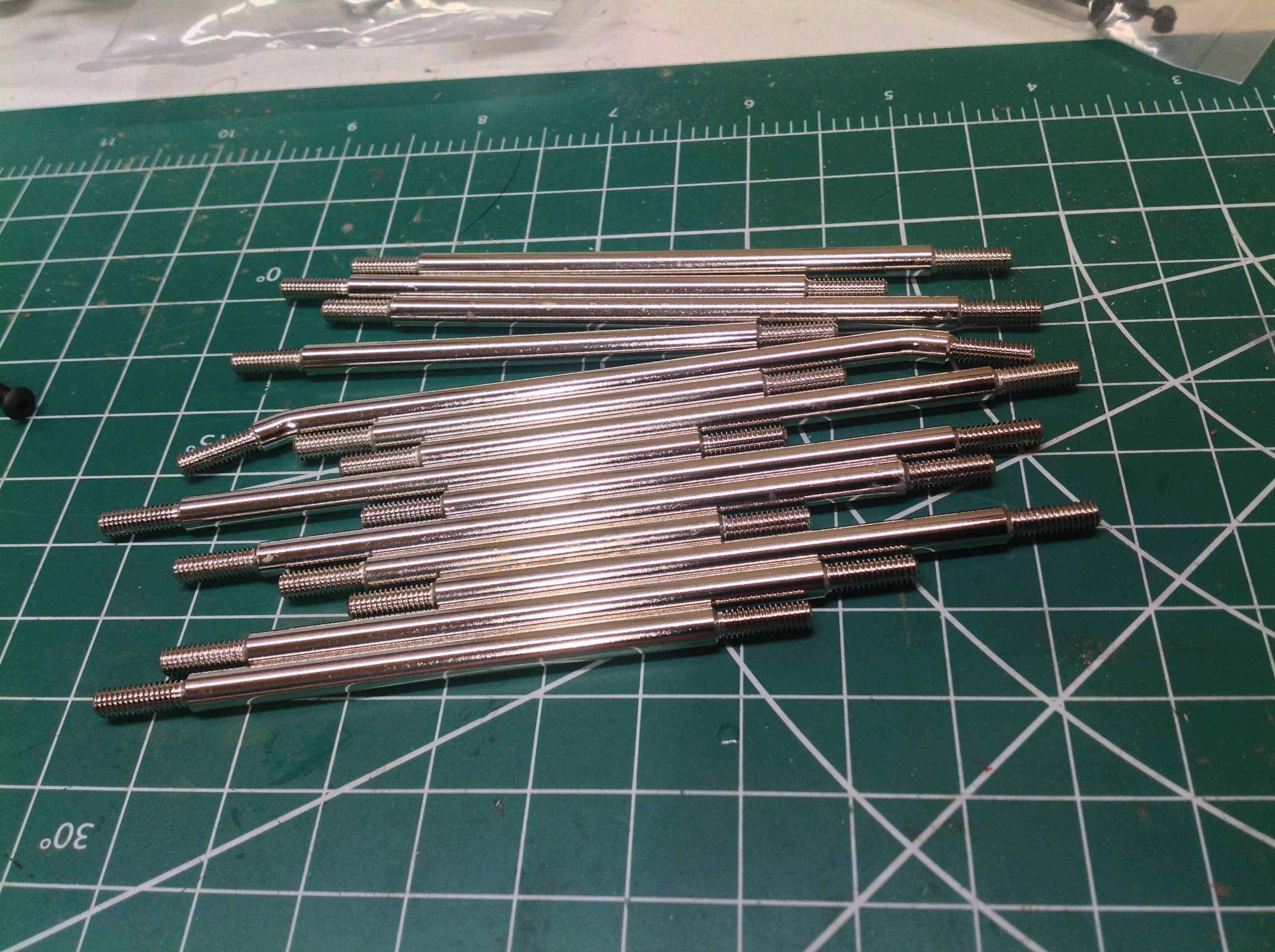
Time to build a massive pile of links. The kit includes 5mm solid
steel links to build the chassis in any of three wheelbase options:
11.8" (300mm), 12" (305mm), or 12.3" (313mm). I'm using the
longest wheelbase option. There are 4 rear suspension links, 3
front suspension links, a panhard bar, a steering link, and a drive
link. That's 10 to make. Each uses a pair of plastic ends
and plastic pivot balls. Note that the steering link is behind the
axle (BTA) which keeps it out of the way of obstacles.
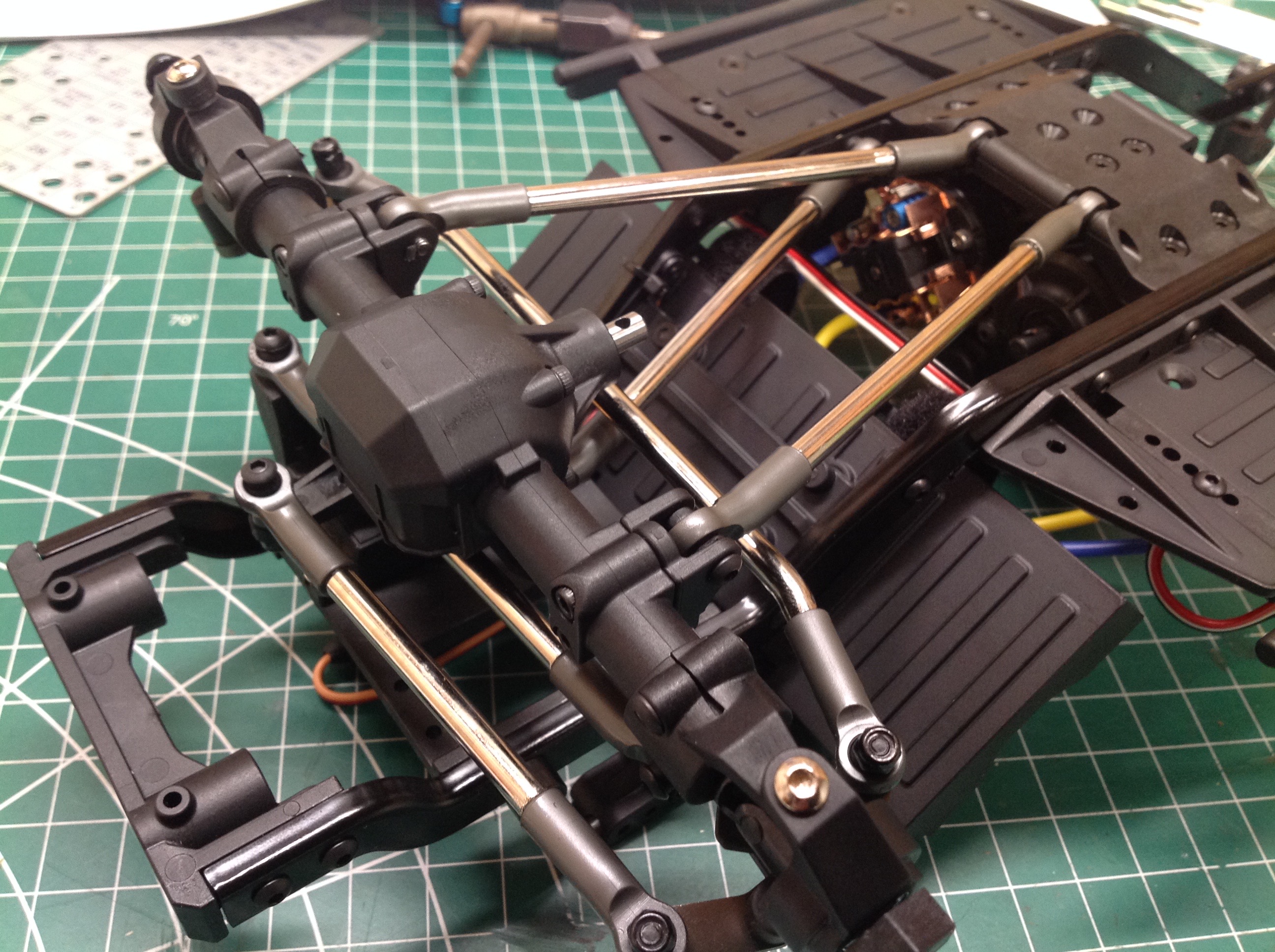
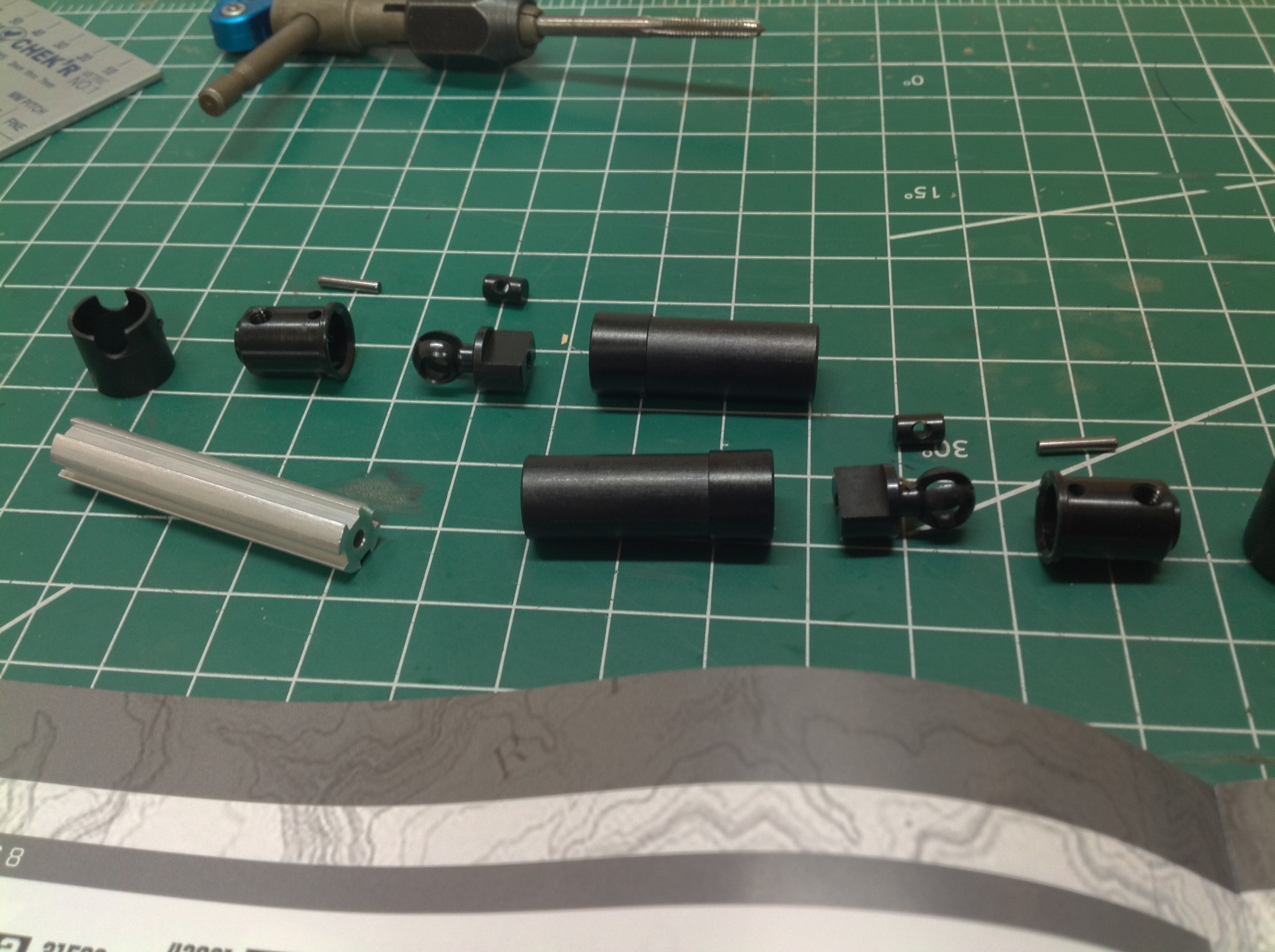
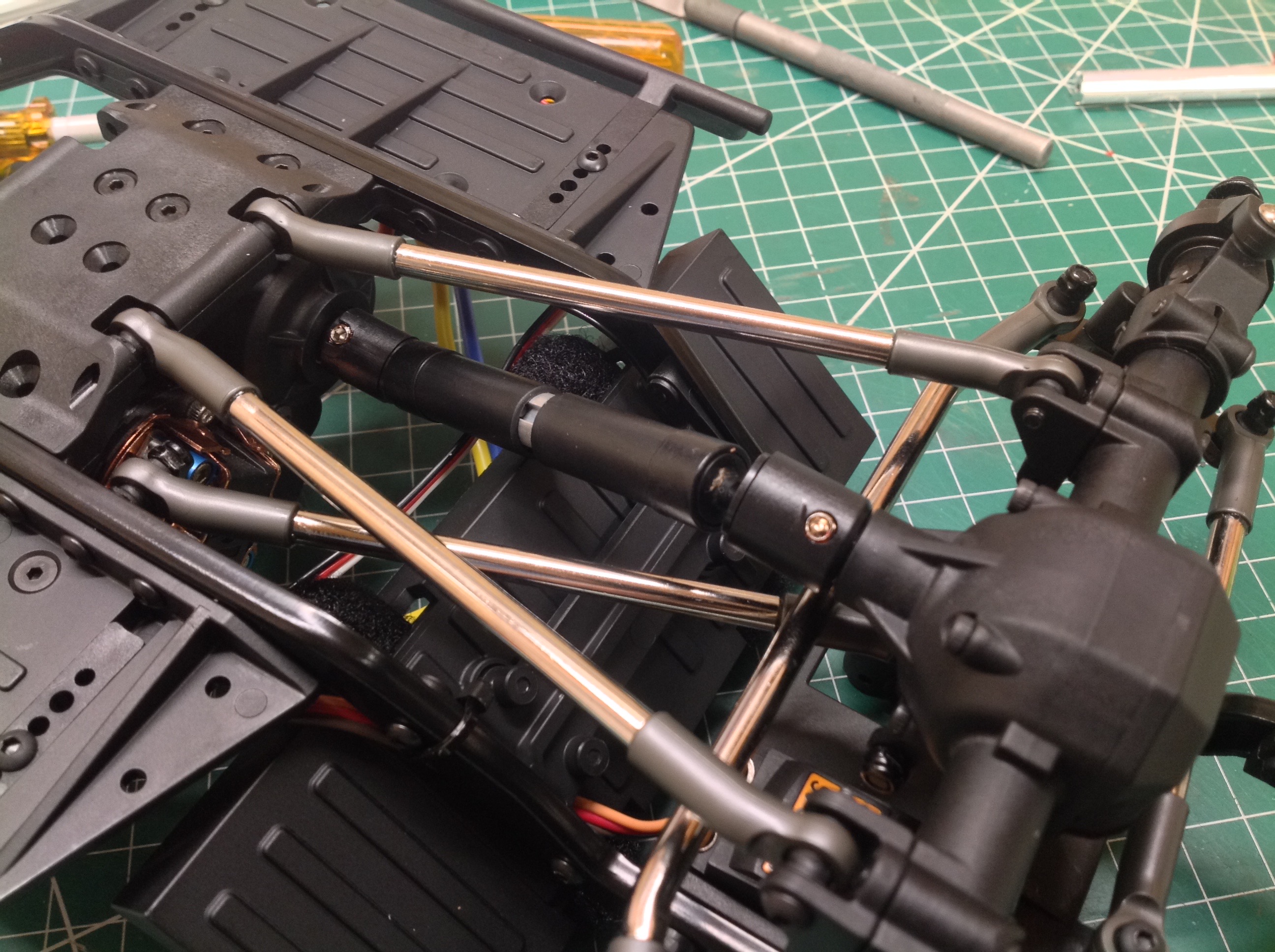
The multi-part drive shafts use plastic bodies, steel universals, and an
extruded aluminum sliding spline. They seem very durable.
Rear drive shaft is shown installed on the right.
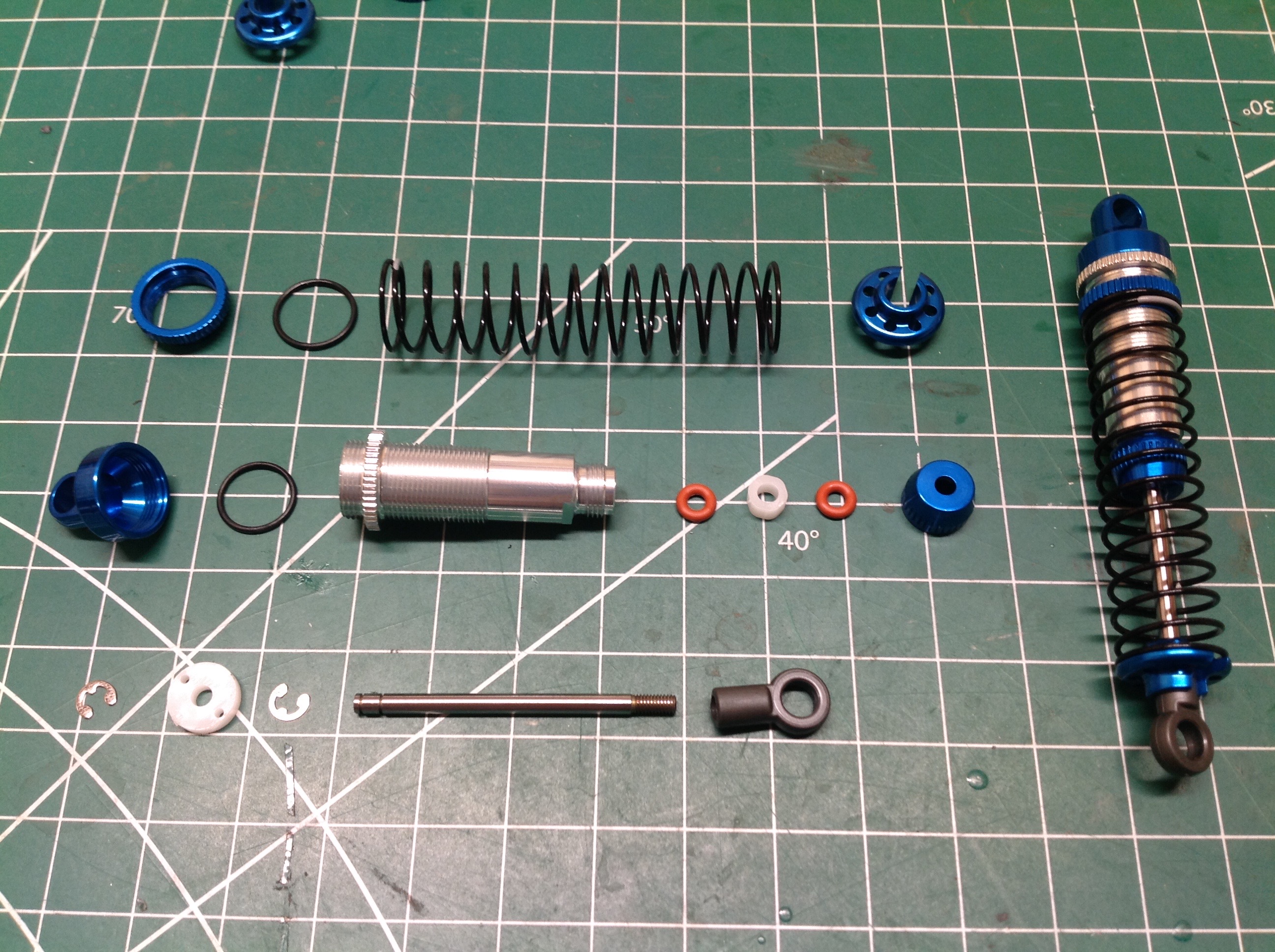
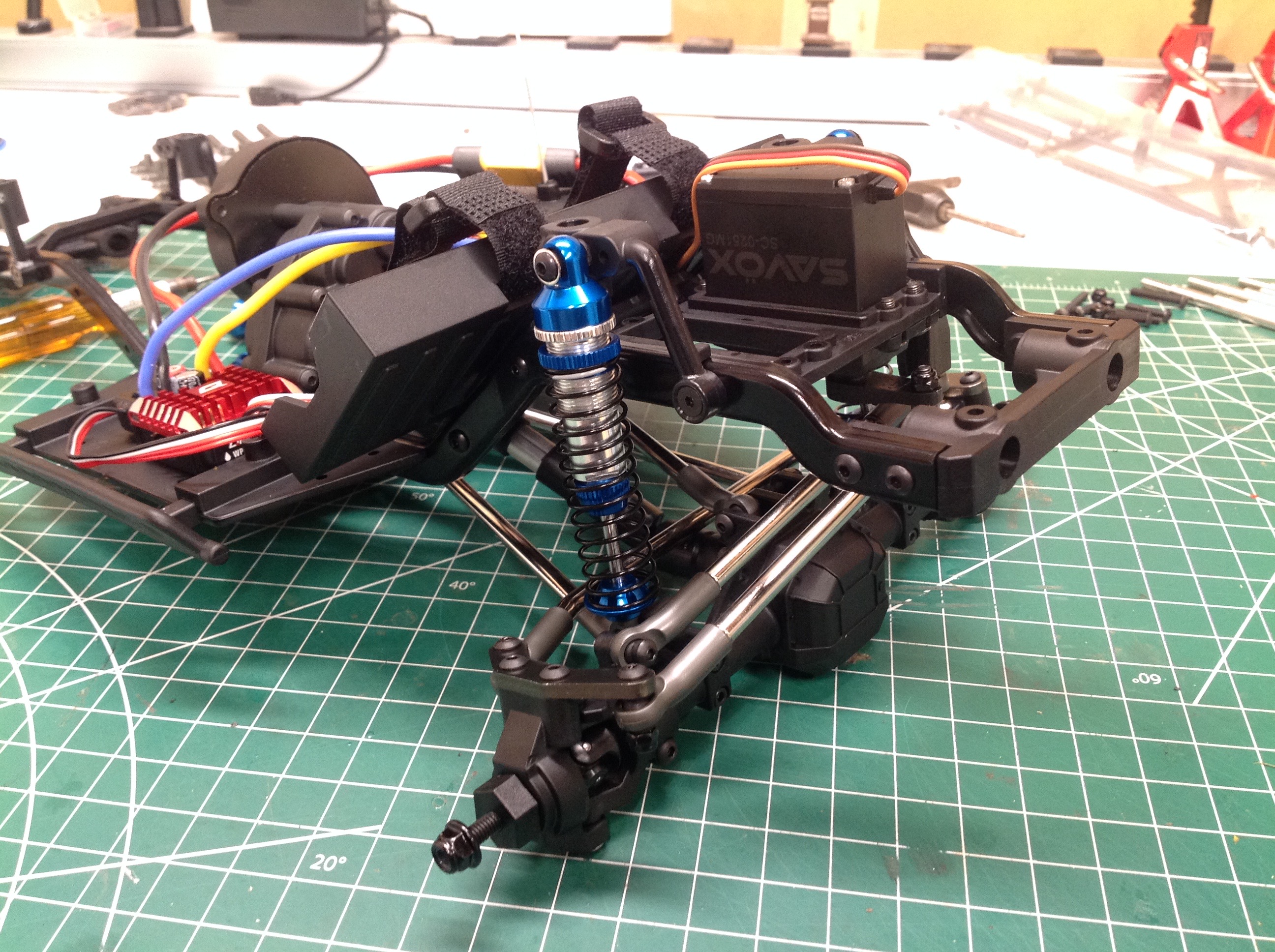
The shocks use a machined aluminum body, caps, and spring perches as
shown. These are really high quality shocks with a nice soft
spring rate. The picture on the right shows how tight the area is
where the shock passes between the various links to connect to the axle.
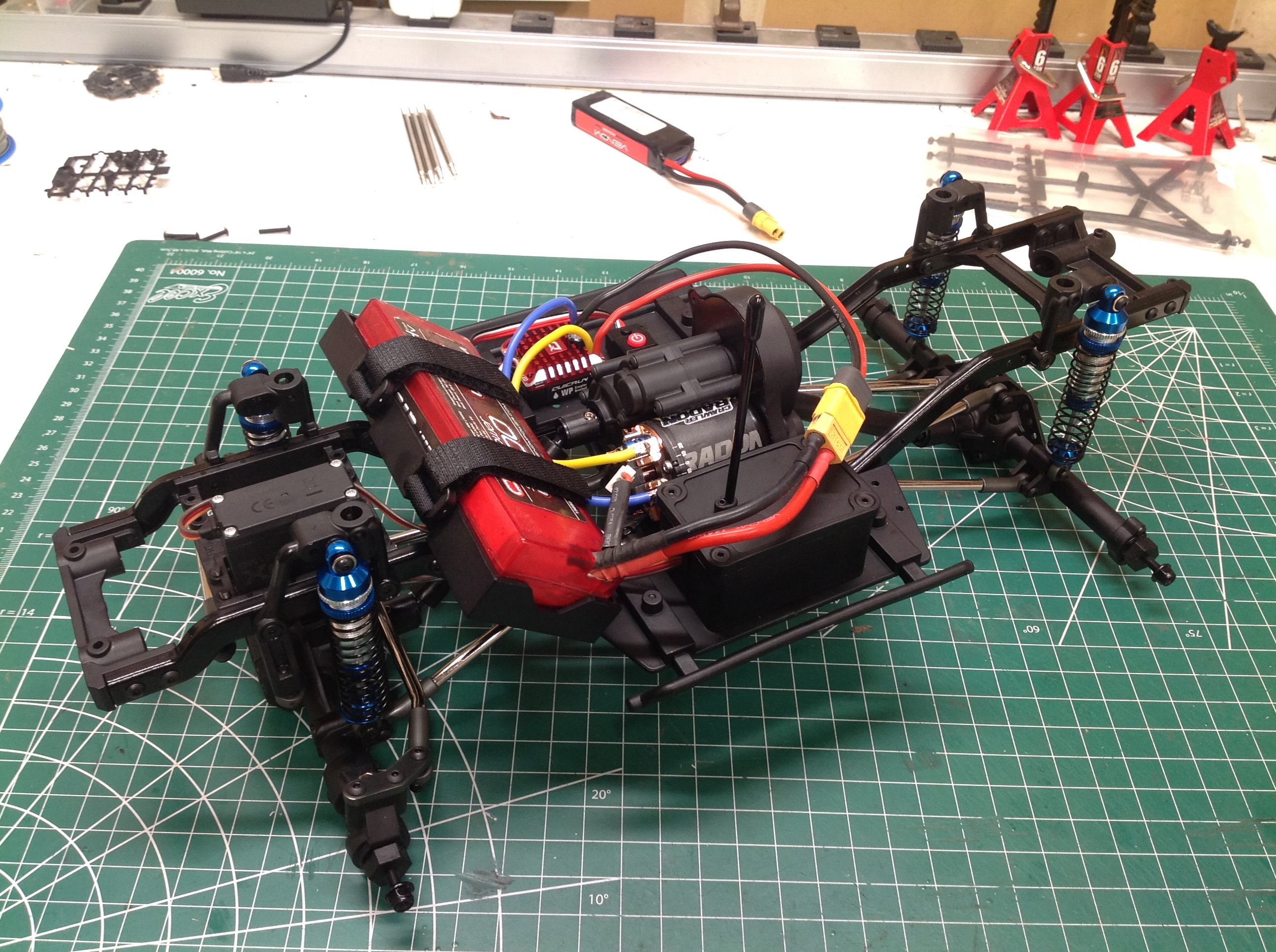
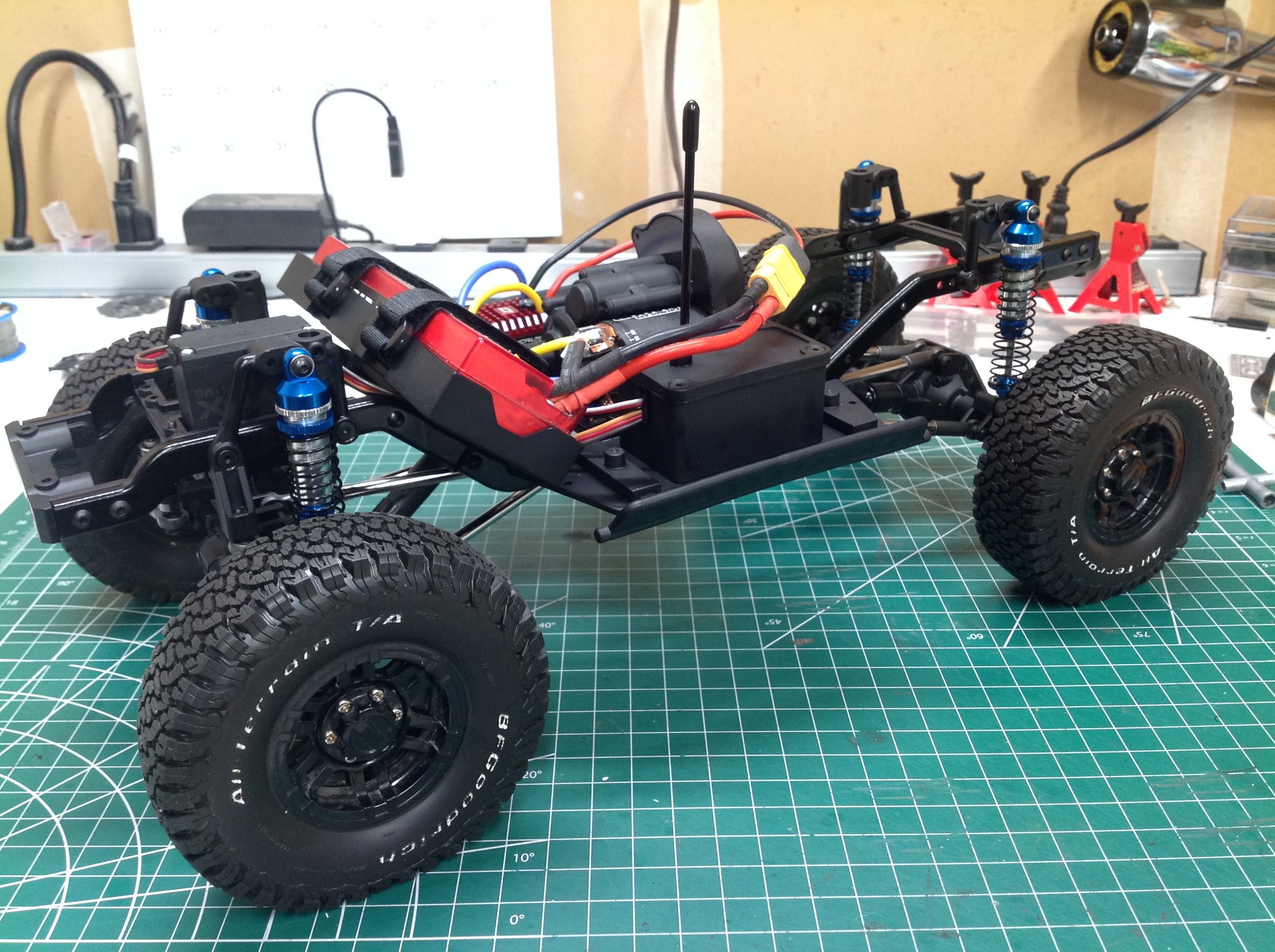
Here's the completed chassis with a battery test fit and ready to
go. This is always an exciting part of the build as it allows
everything to be tested out before the maiden run. This is the
point at which I program my radio for steering end points and other
parameters. Note that I did not install any body posts because I
will not be using them.
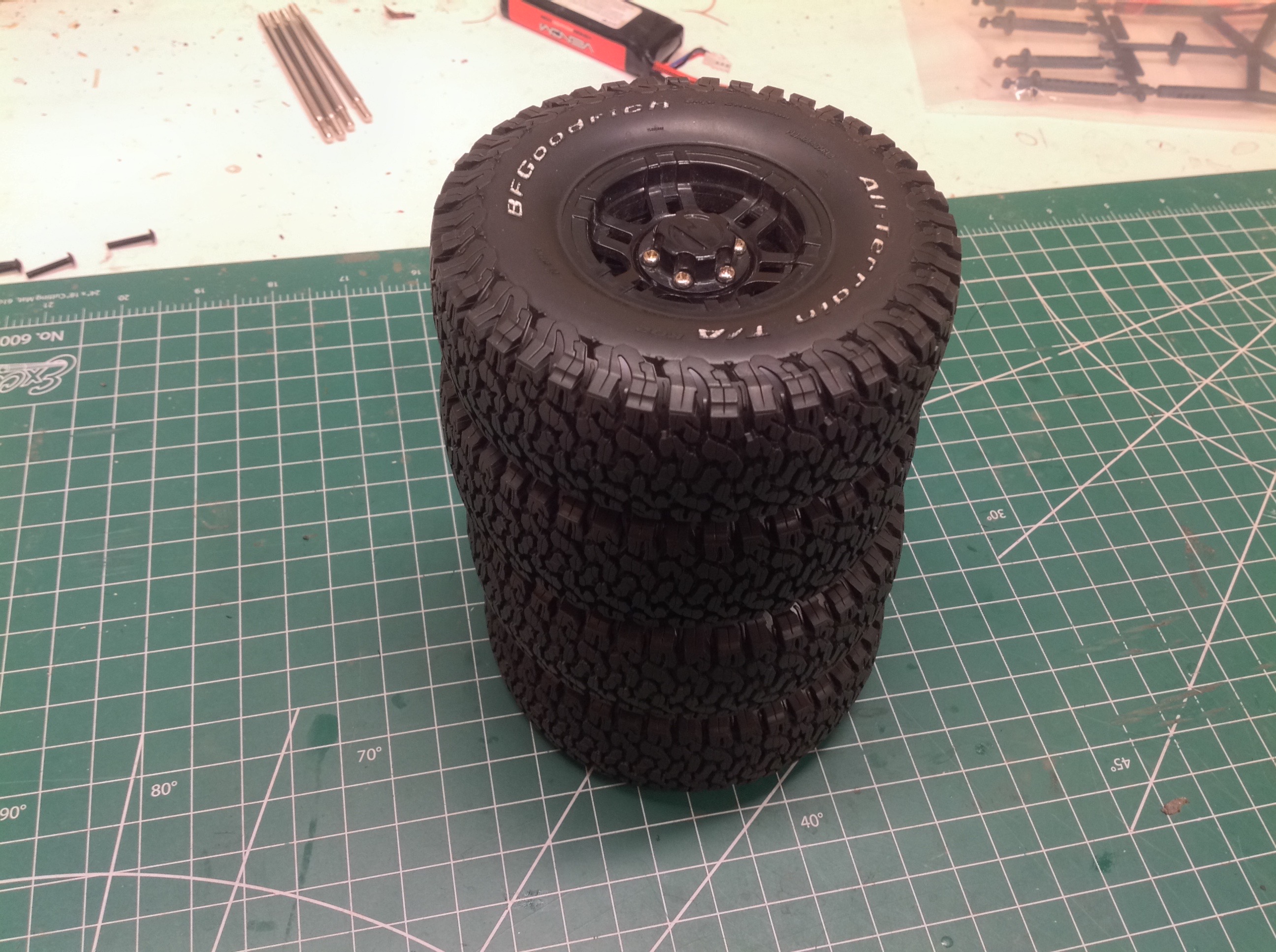
I'm re-using these Proline BF Goodrich All Terrain T/A tires which I had
on a LEGO model for years combined with a set of plastic beadlock
wheels from my Gmade Komodo. In both cases, I think these are a
perfect match for a chassis destined for a Toyota 4Runner. The
right hand image shows the completed rolling chassis. This is the
state it was in when I went out for the first test runs and pronounced
it awesome.
©2020 Eric Albrecht