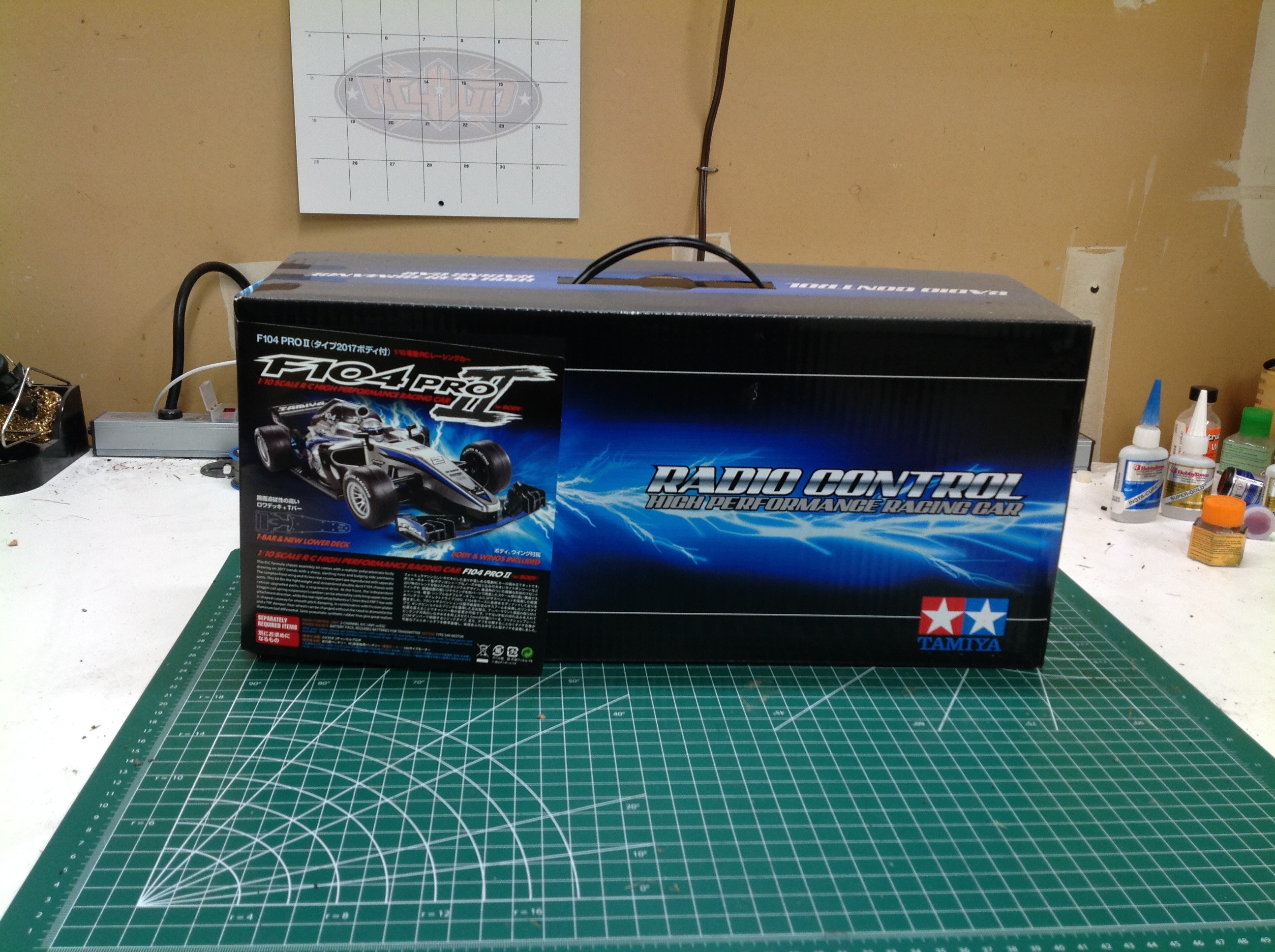
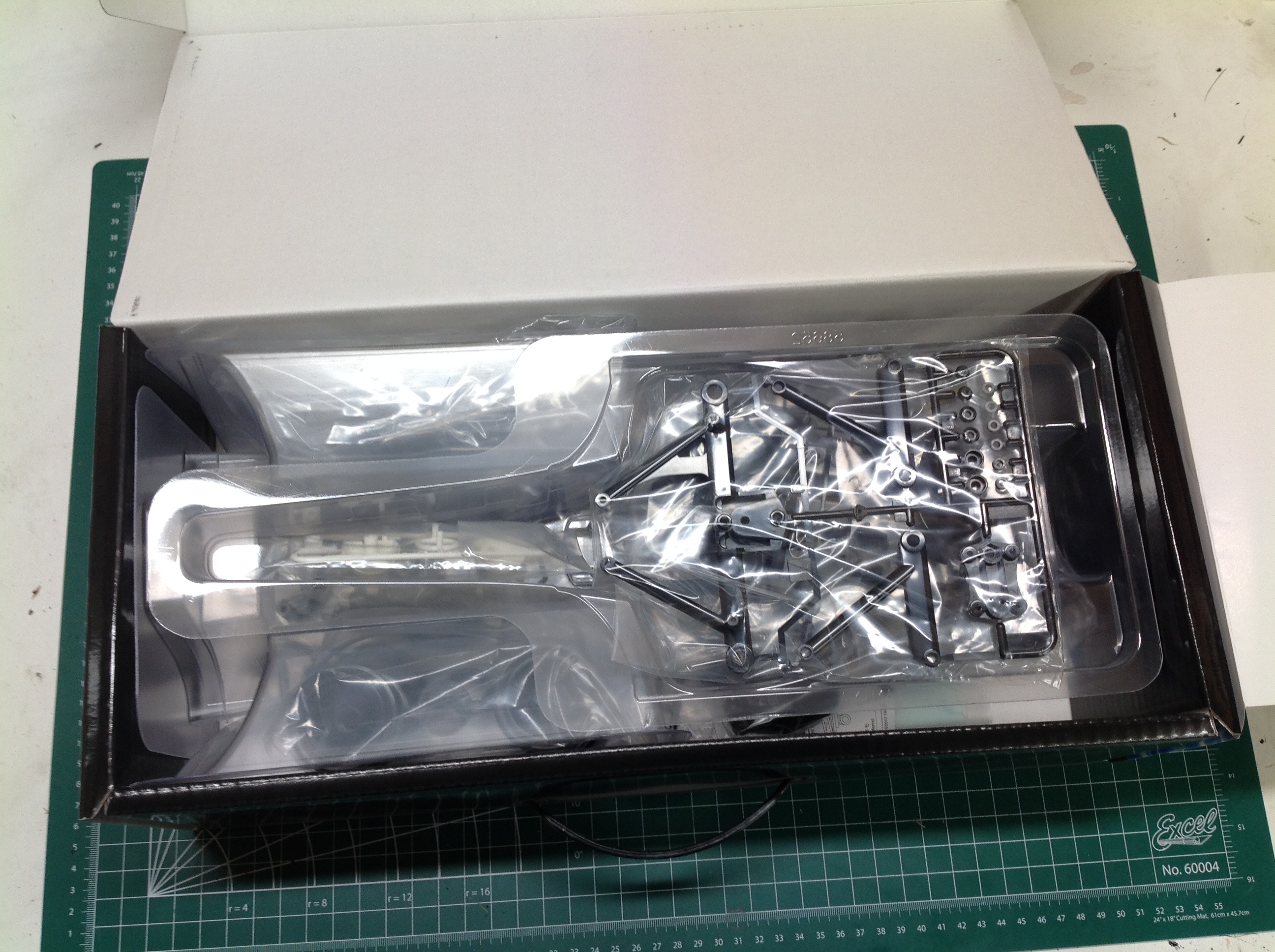
The box the F104 Pro II comes in is so small that I was afraid there wasn't going to be a body in there as advertised. I needn't have worried. The box is packed very full with all the parts hidden under the body shell.
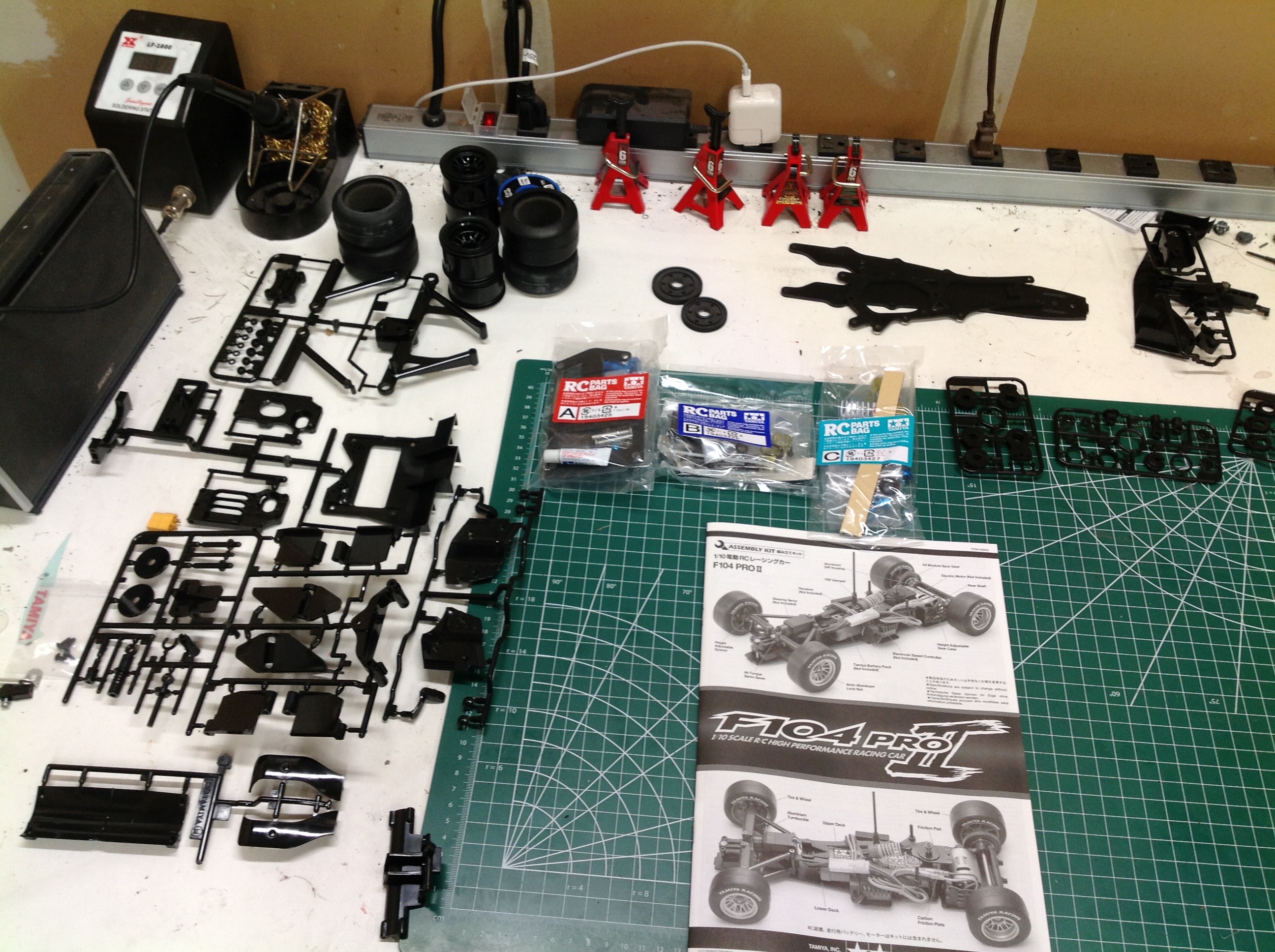
Here are the parts laid out on my build table. Compared to other chassis types, a Formula 1 chassis is pretty simple. I found the hardware the most interesting because it consisted of quite a few types of parts I had never seen before. The chassis uses a pair of FRP plates and the rest is plastic parts trees.
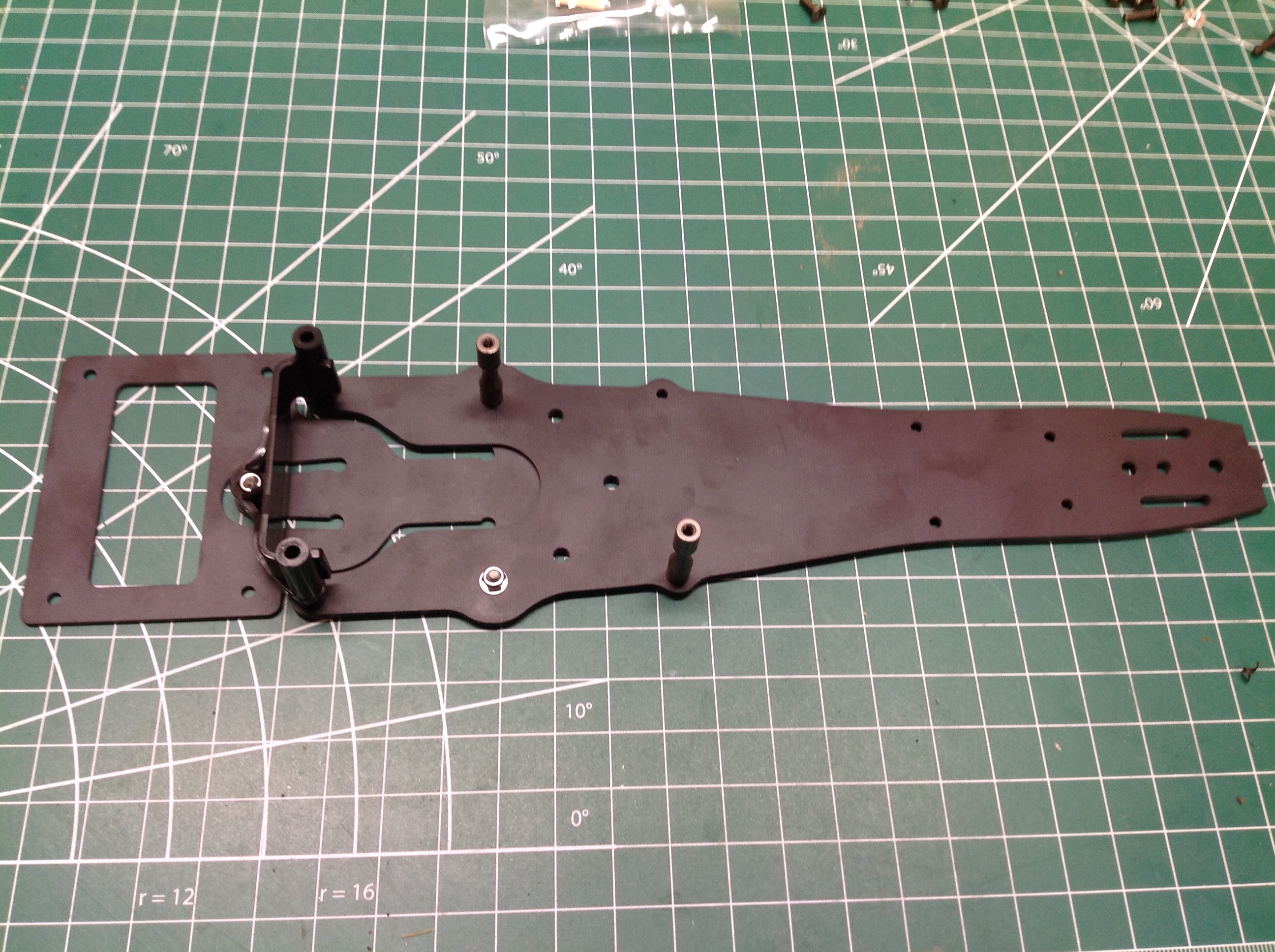
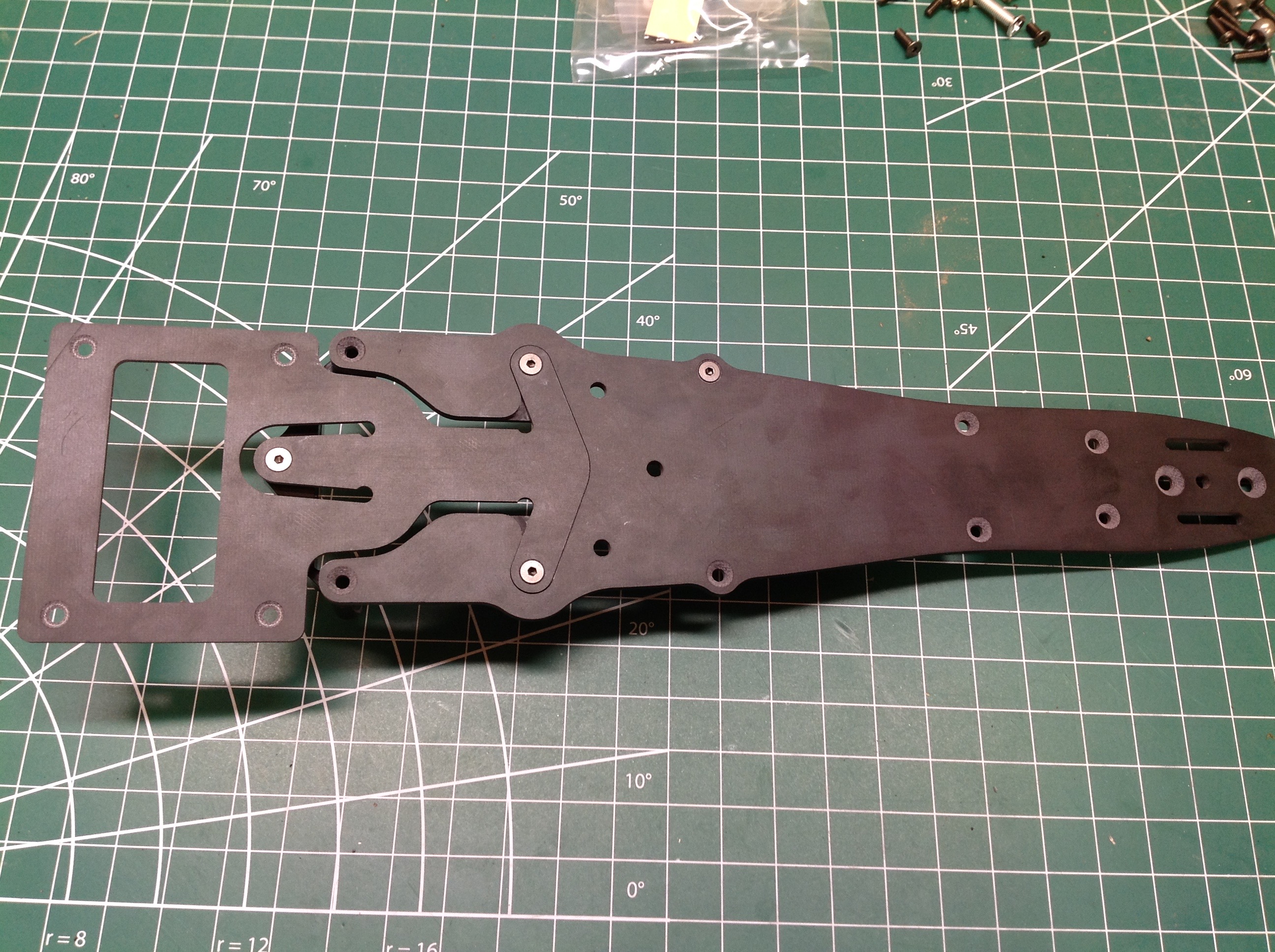
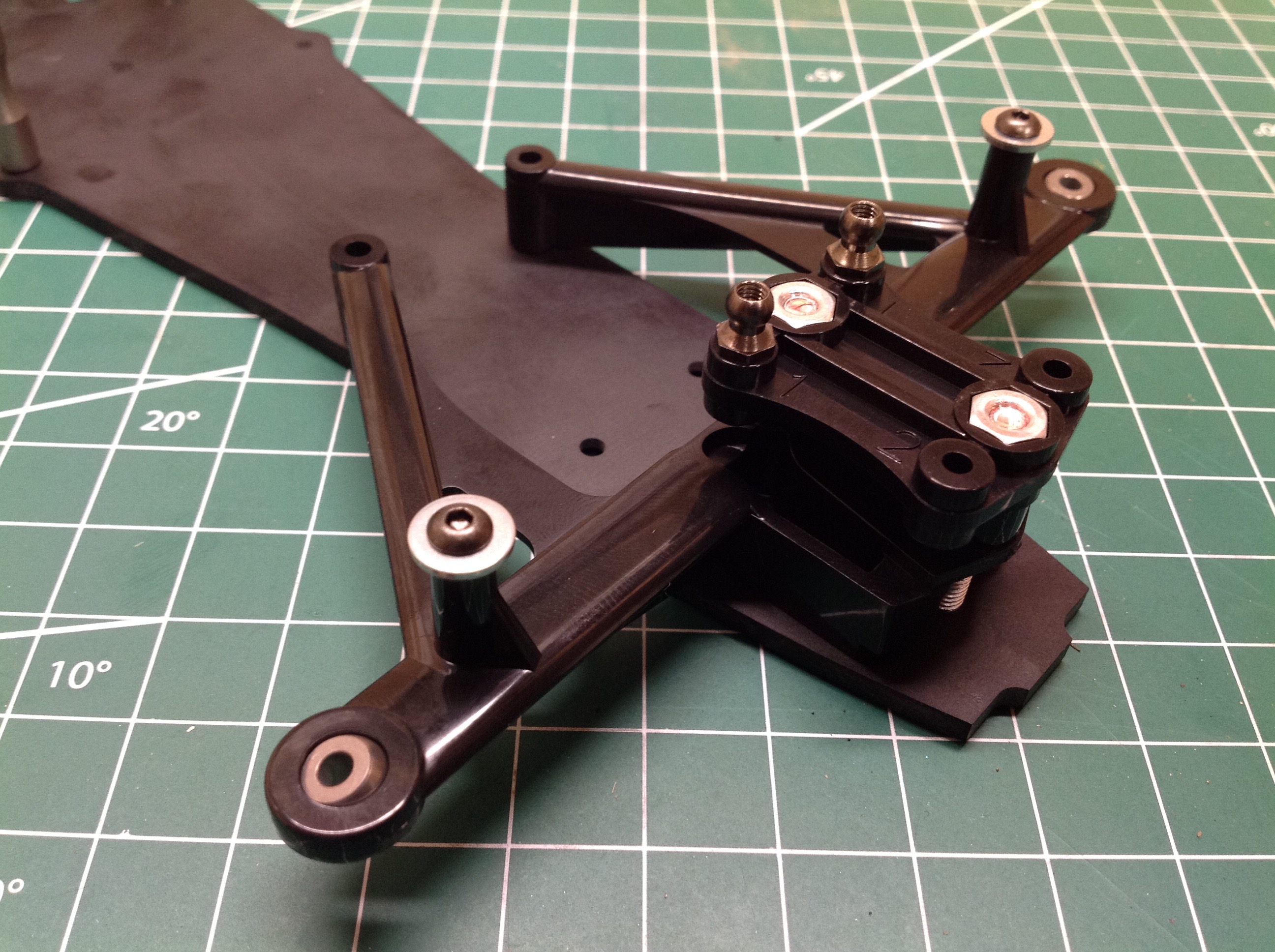
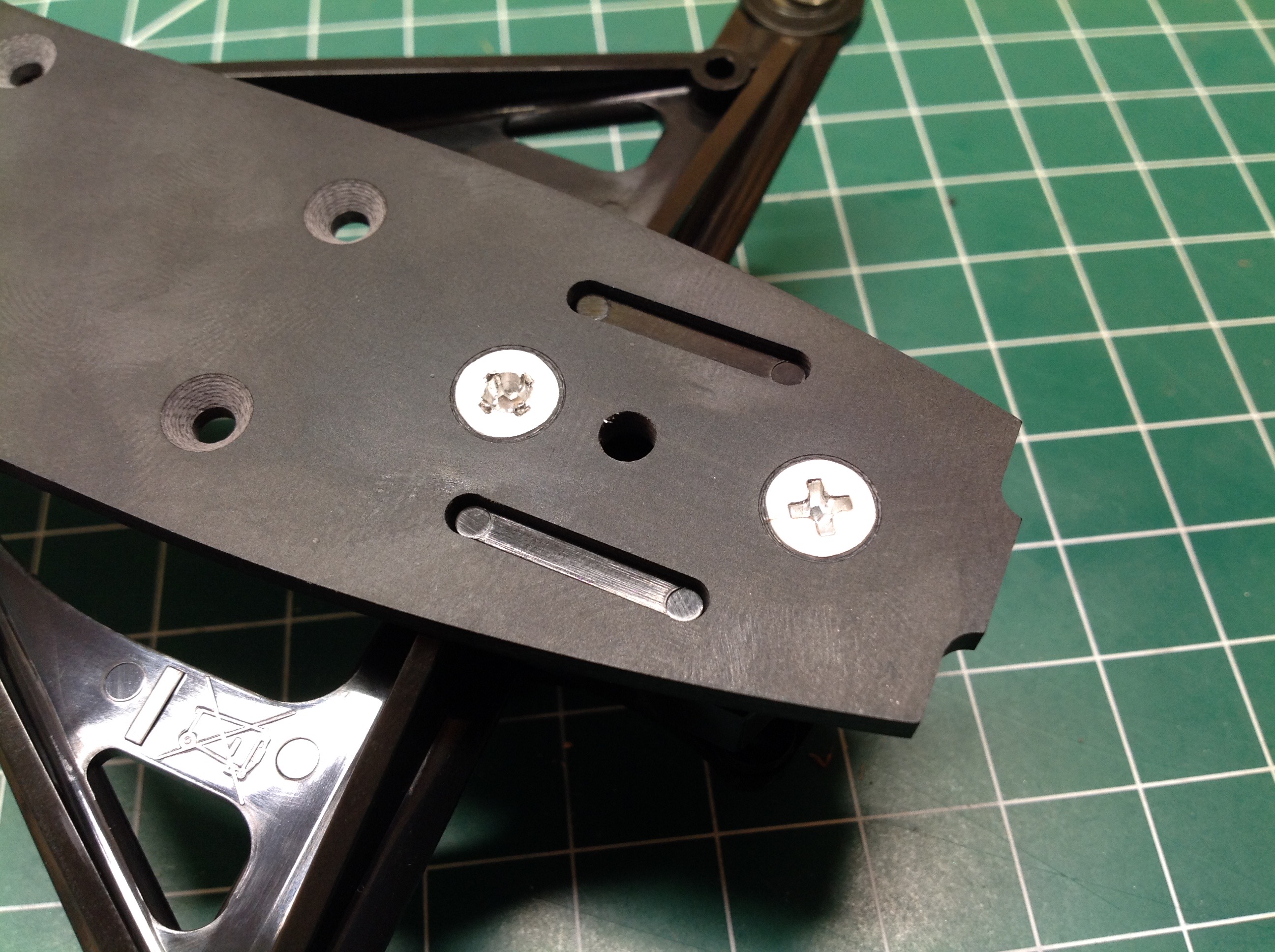
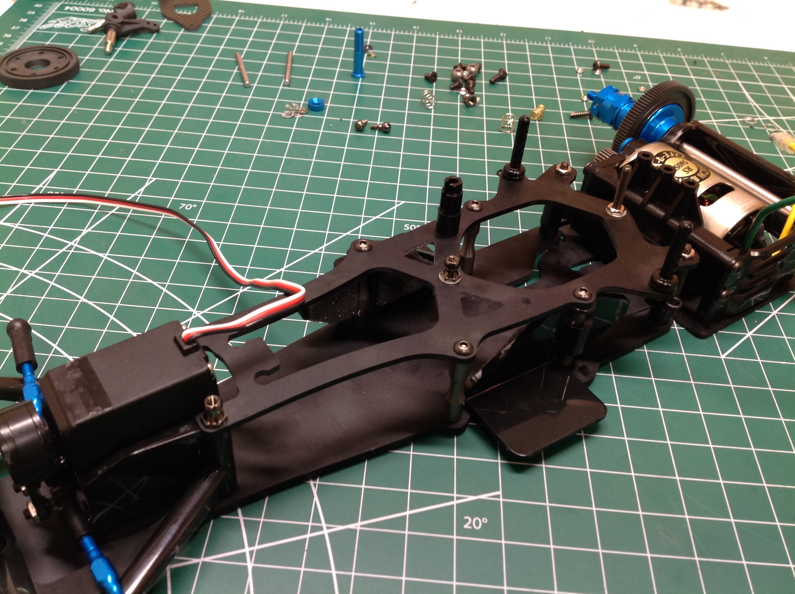
Here's the chassis. Those diagonally spaced vertical posts support the upper shock deck and also help keep the battery (which sits longitudinally) inside the model. It is possible to add two more posts to make a square pattern so the model is stronger, but these will have to be removed every time you want to change the battery. The picture on the right helps show the way the rear suspension works. Vertical movement occurs by flexing the rear plate near the rear horseshoe cutout (by the left most silver screw in the photo). Rear roll occurs by twisting the narrow section further forward (to the right). This allows vertical movement and roll to be adjusted independently with almost no moving parts.
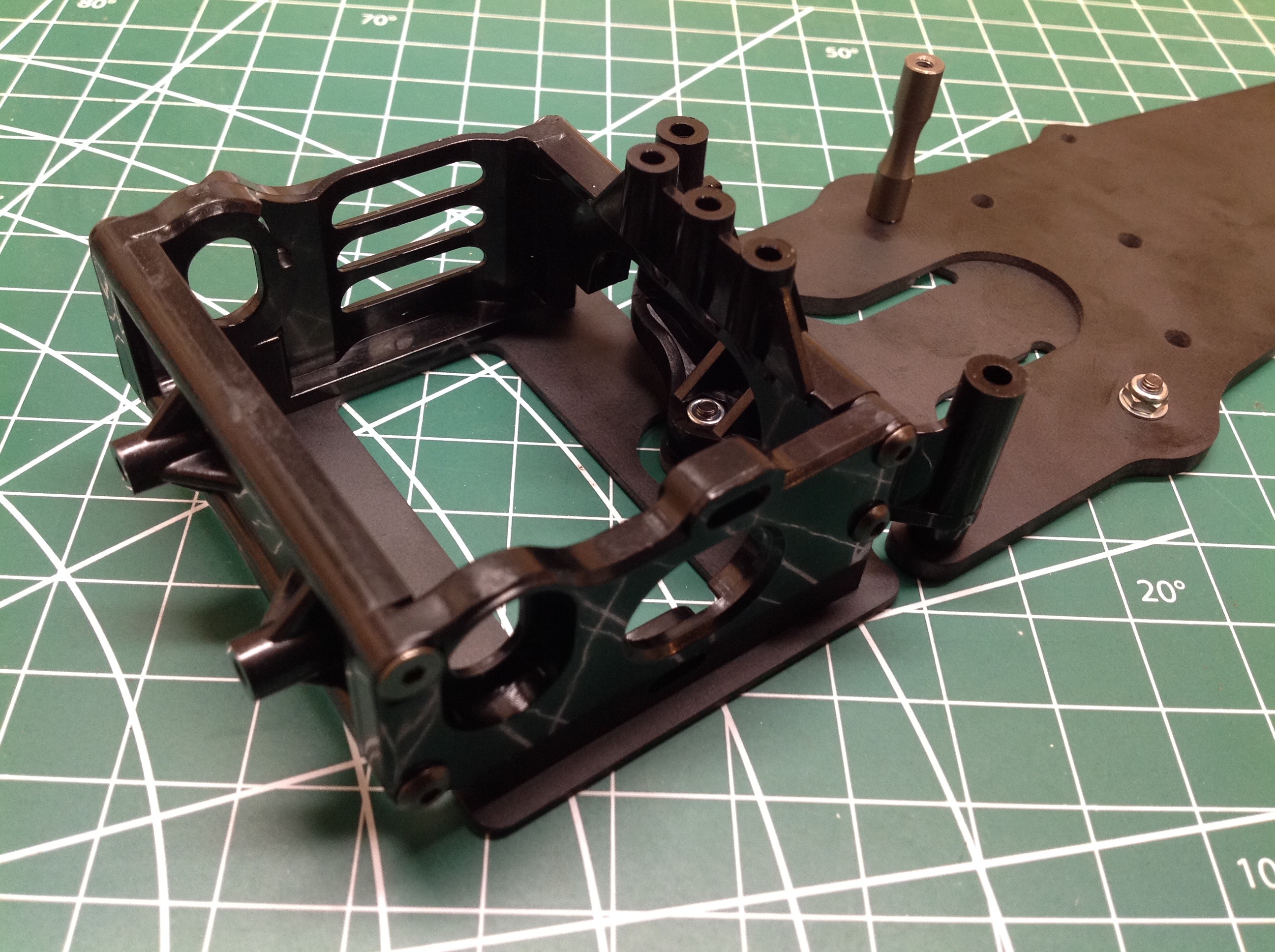
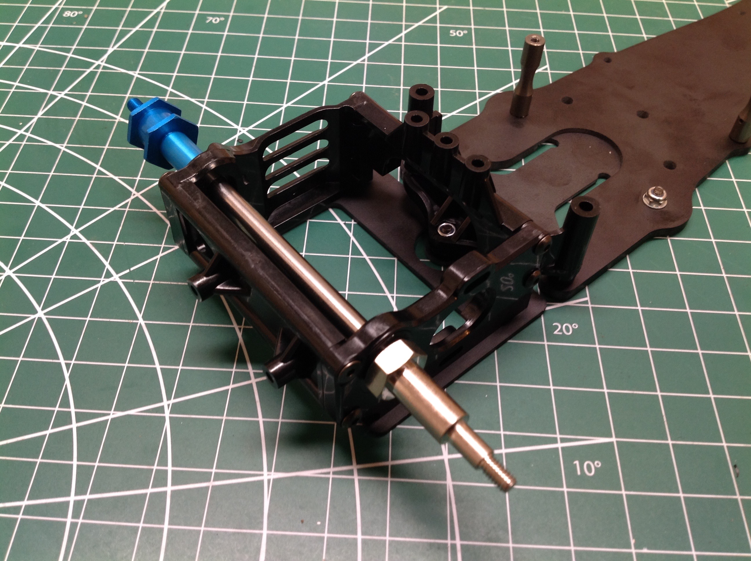
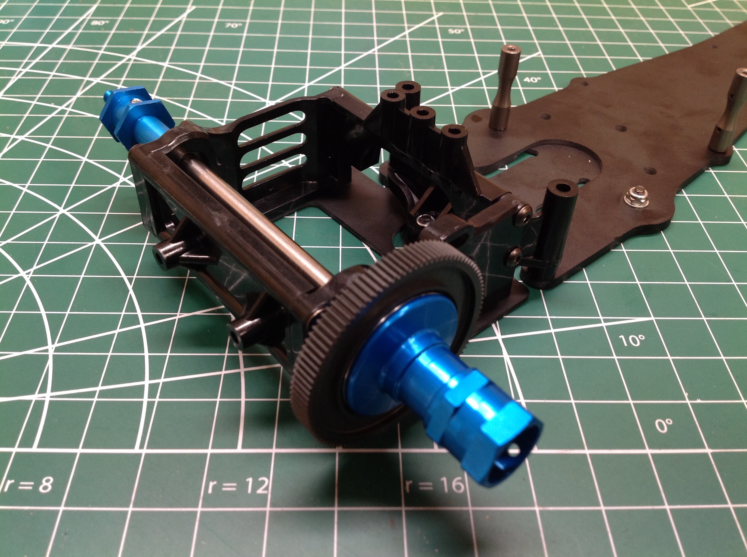
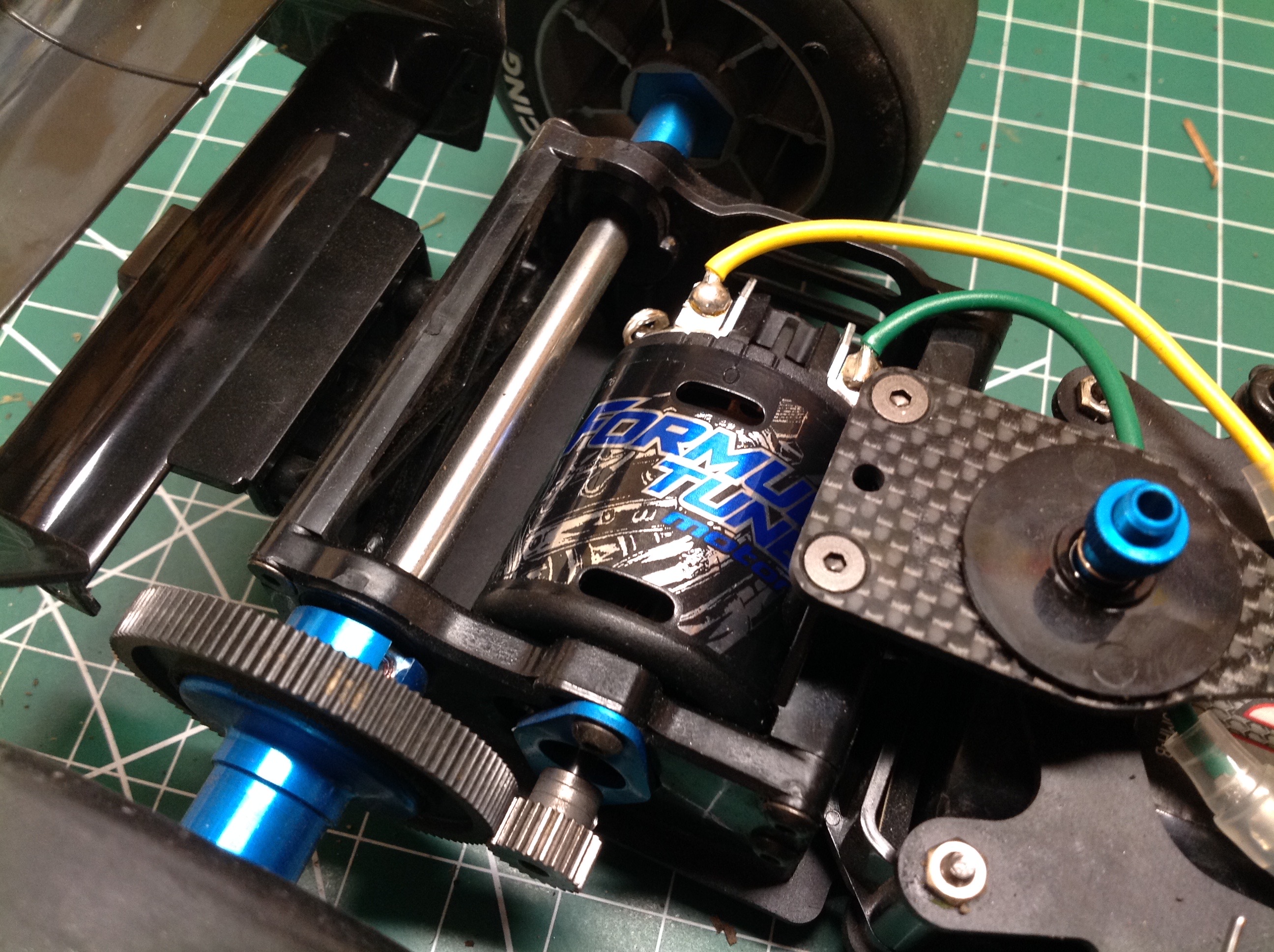
This plastic box attached to the rear chassis plate contains the rear axle and motor and moves as a rigid unit with the rear suspension. The thick axle you see on the right passes all the way through. The blue end will drive the left wheel directly, while the spur gear will float on the silver end and drive the right wheel. Ride height can be adjusted by replacing or rotating the inserts which position the axle in the box.
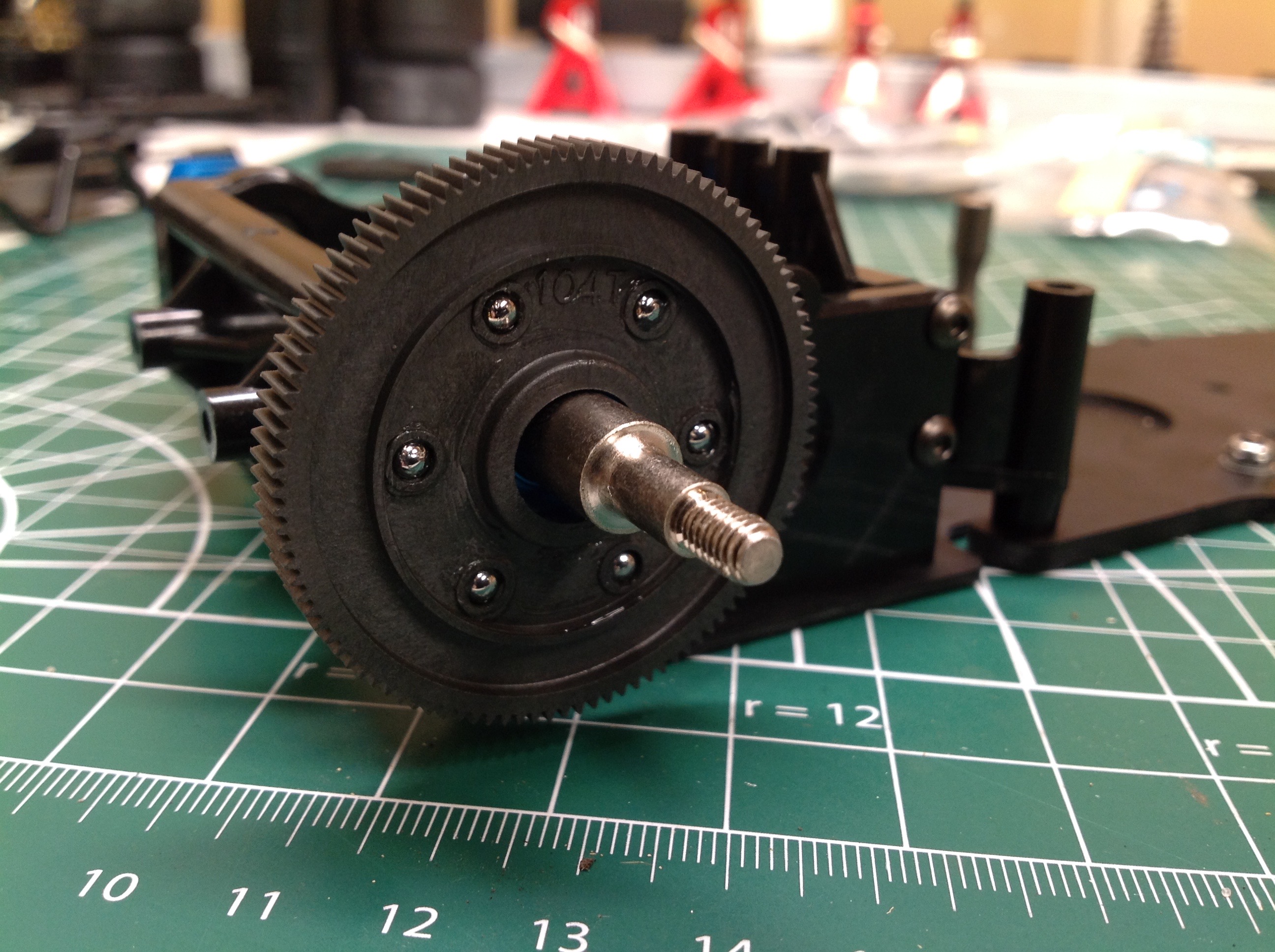
There is a ball differential built directly into the spur gear as shown. This allows for a very thin diff. The completed rear axle is shown on the right. Under normal operation the spur will drive both sides evenly, but differential speed is allowed by rolling the balls. Slipping the balls is also possible allowing torque to be relieved if it gets too high.
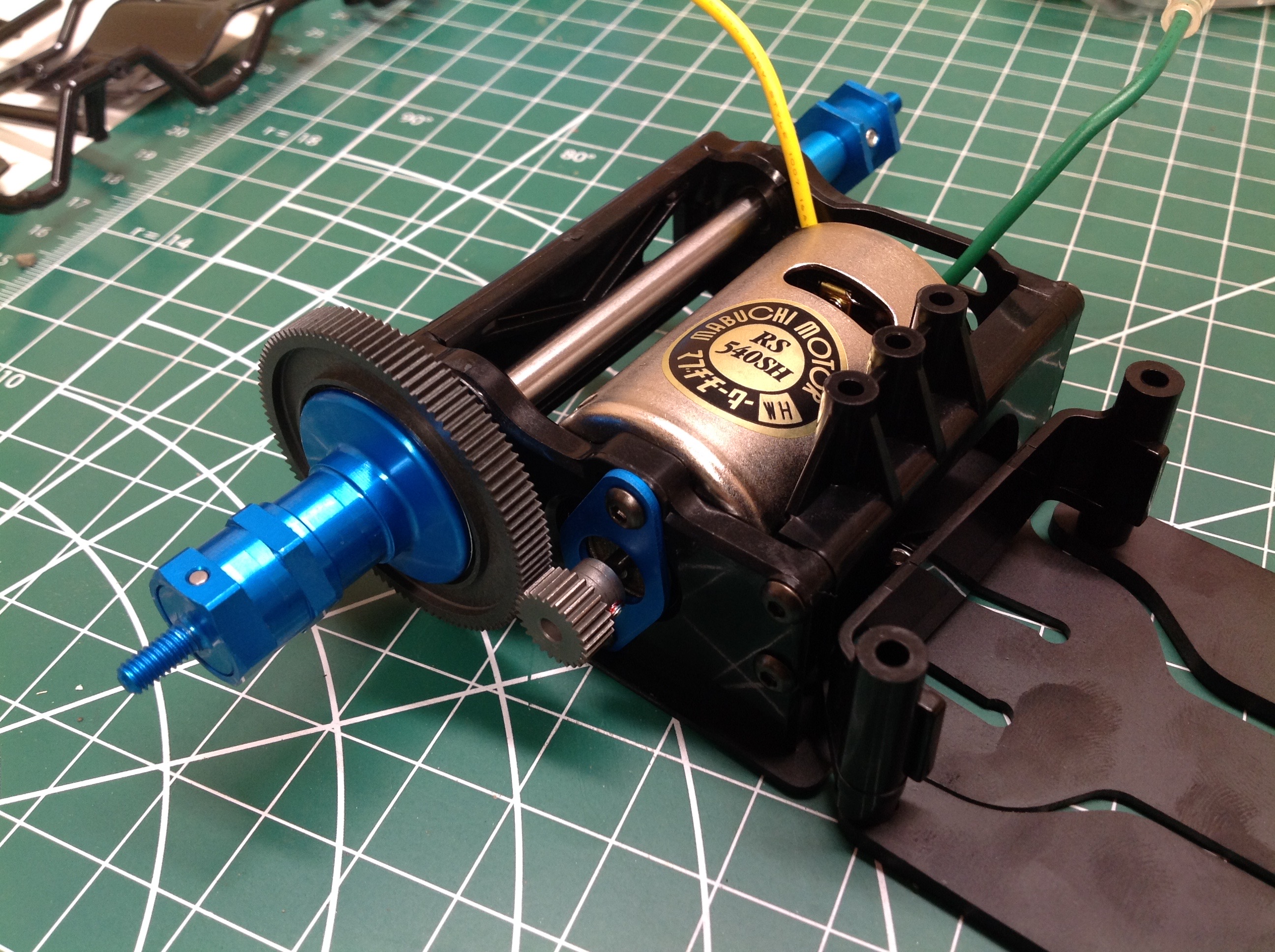
Now the motor can be installed. This kit actually didn't come with a motor, but I started with a standard silver can while waiting for my Formula Tuned motor to arrive. A wide range of pinion sizes are possible ranging from 20 to 29 teeth, and the stock 104 tooth spur can be swapped for a 93 tooth version for even more speed. I am using a 25 tooth pinion that came with the kit. The pitch is 0.4 mod (equivalent to 64p).
Now we can start on the front suspension. The lower arms are effectively rigid and are bolted to the chassis plate so they cannot pivot. Ball joints are pressed in at the ends. Two very large screws are used to attach the front bulkhead from the bottom. It turns out these are very soft aluminum screws so I stripped out the cross recess on one of them.
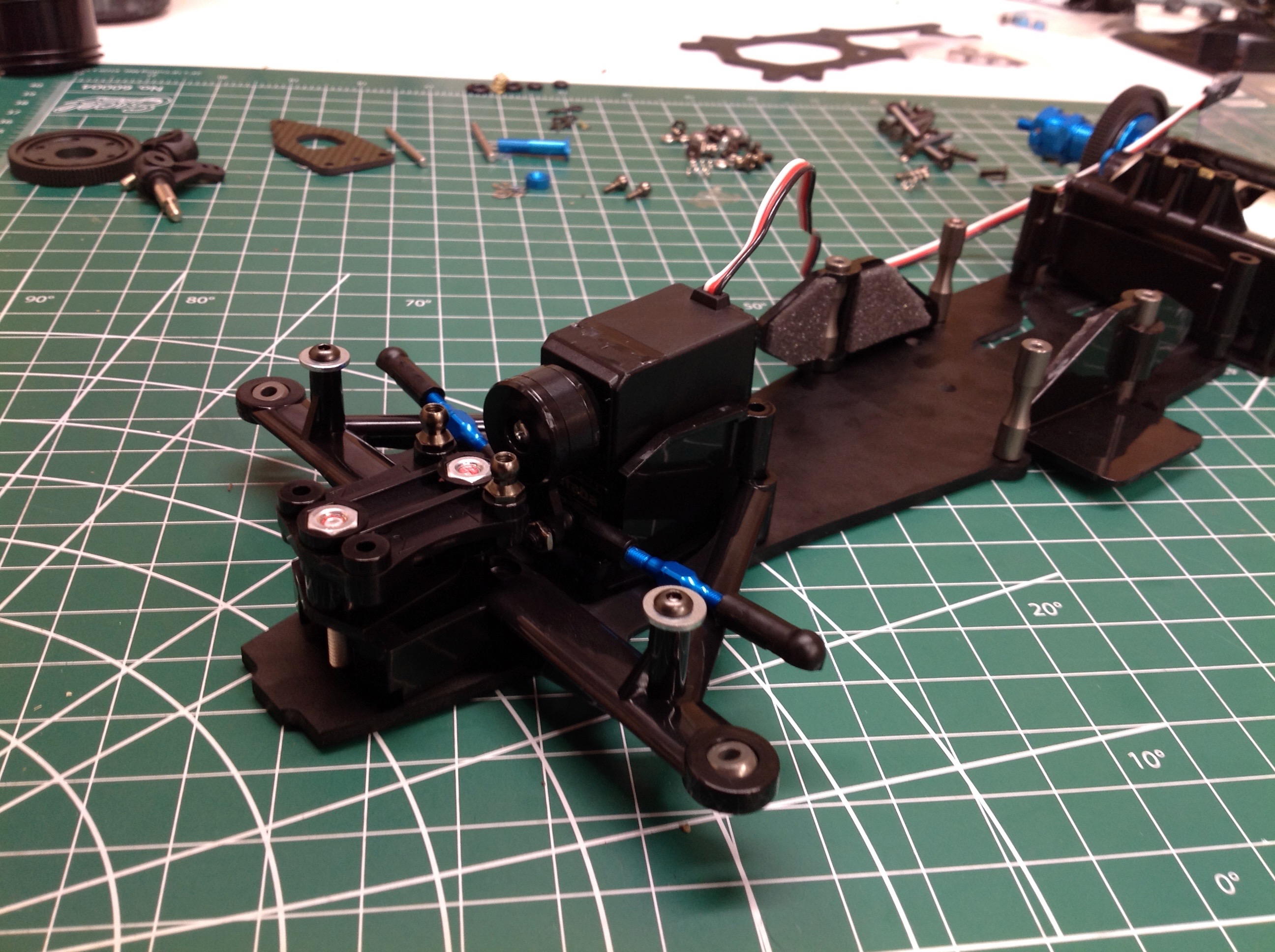
The steering servo has to be modified by cutting off the mounting tabs, so there is no point in using an aluminum bodied servo. The servo is mounted vertically and the servo saver attached directly to the output. The upper deck then goes on to flank the servo and reinforce the chassis. The front steering links are turnbuckle type which allow adjustment of toe angle.
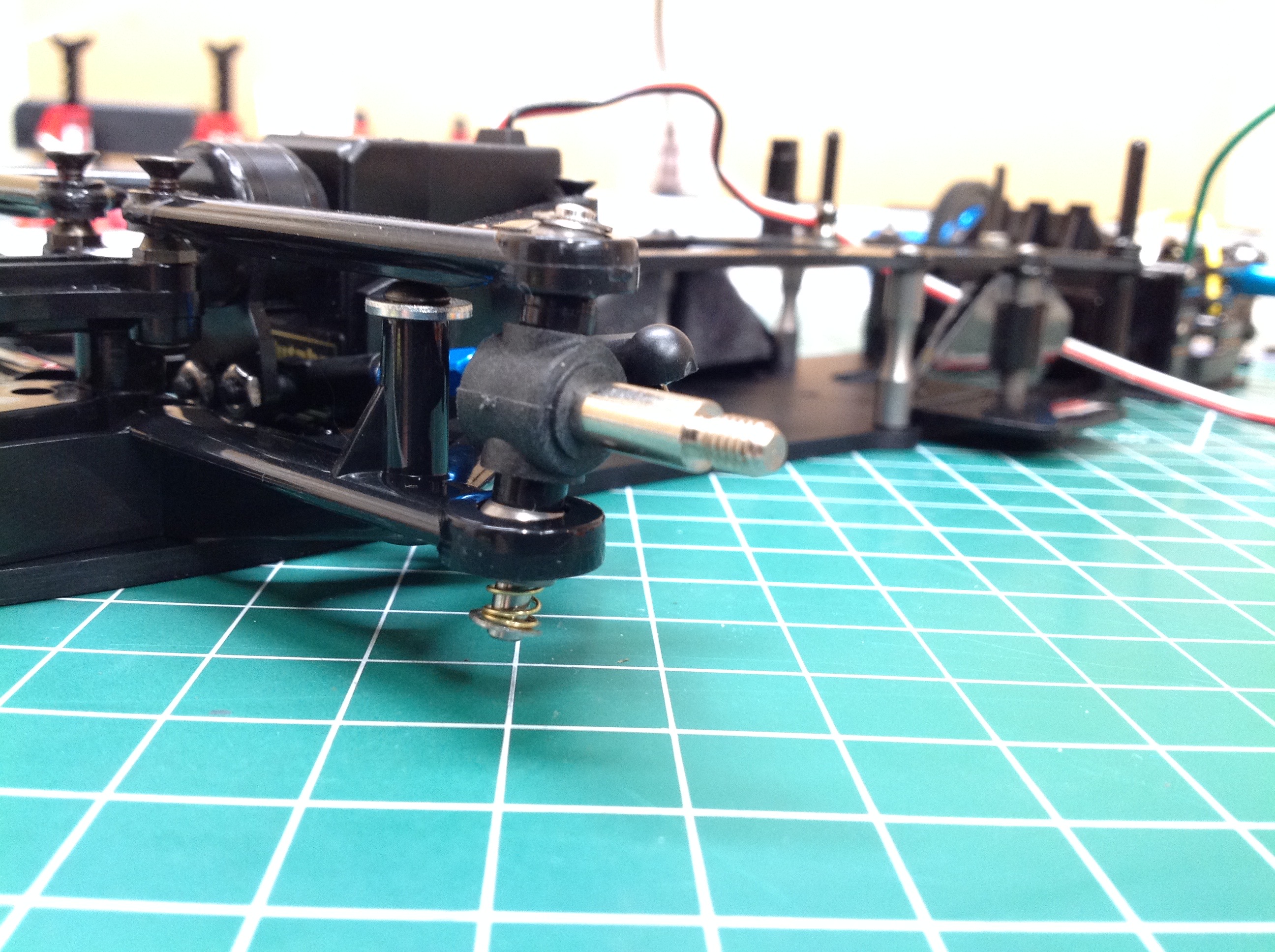
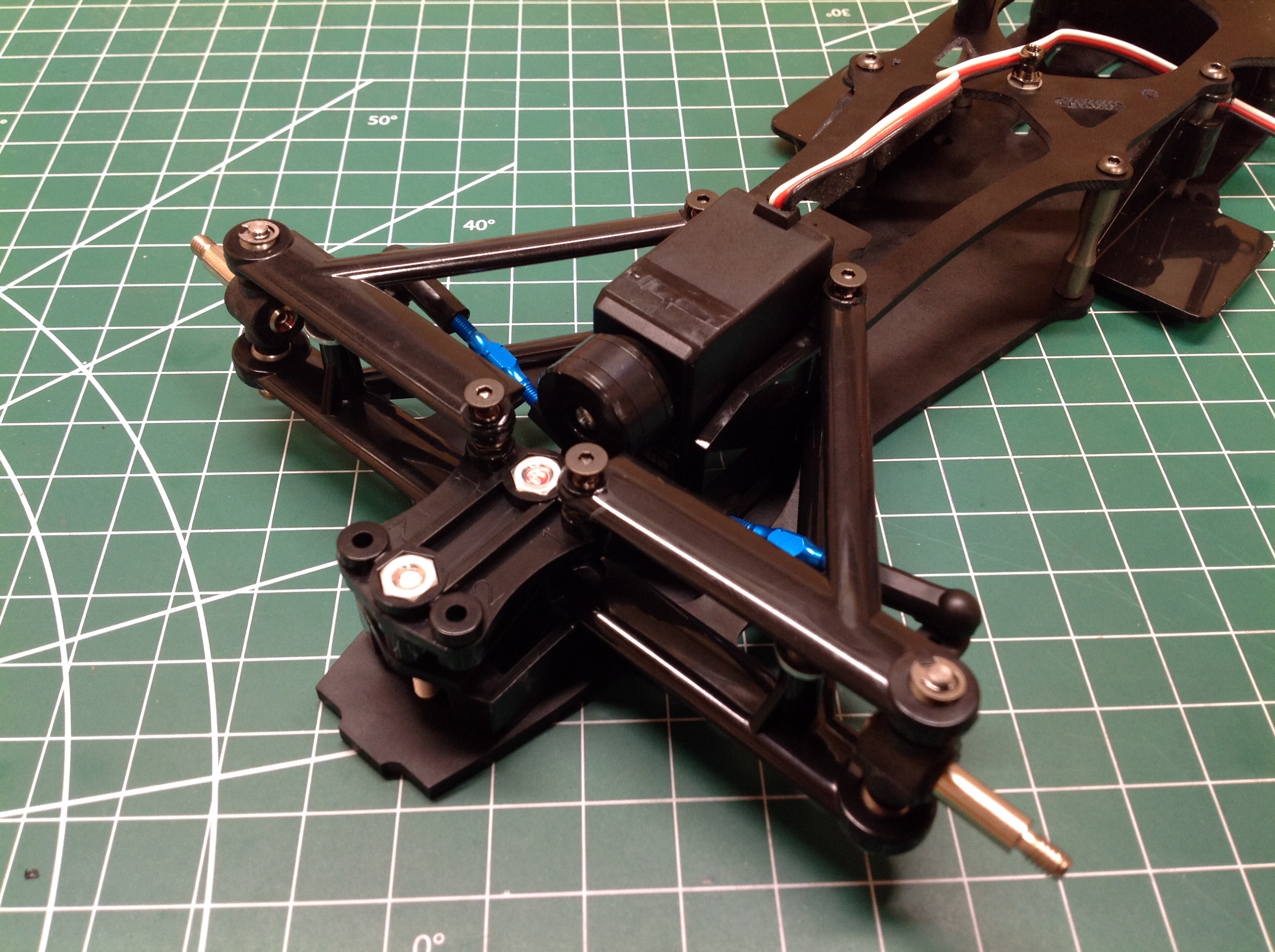
These pictures show how the front suspension works. In the left hand picture you can see the tiny spring which sits beneath the lower arm on the steering axis. This allows the entire steering knuckle to move up and down, taking the upper suspension arm with it. The upper arm is not adjsutable for camber or caster, but it does pivot up and down on ball joints. Ride height can be slightly changed my rearranging the spacers which go above and below the steering knuckle.
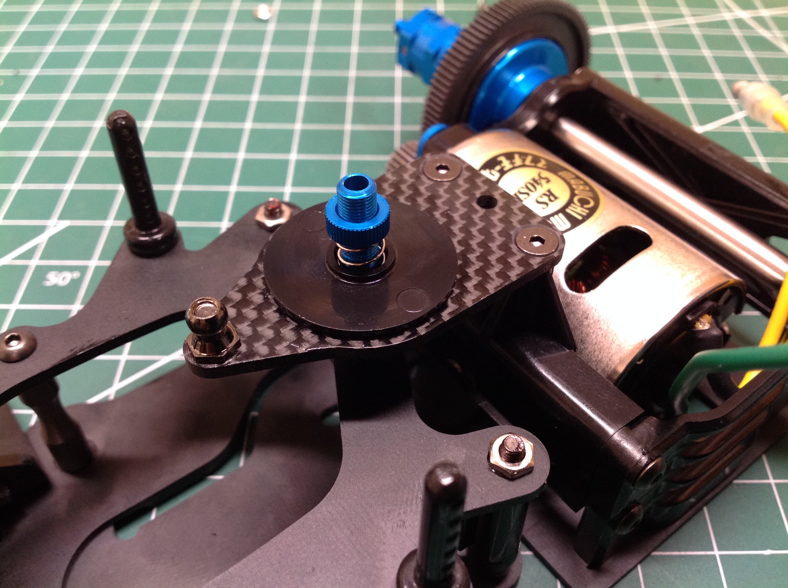
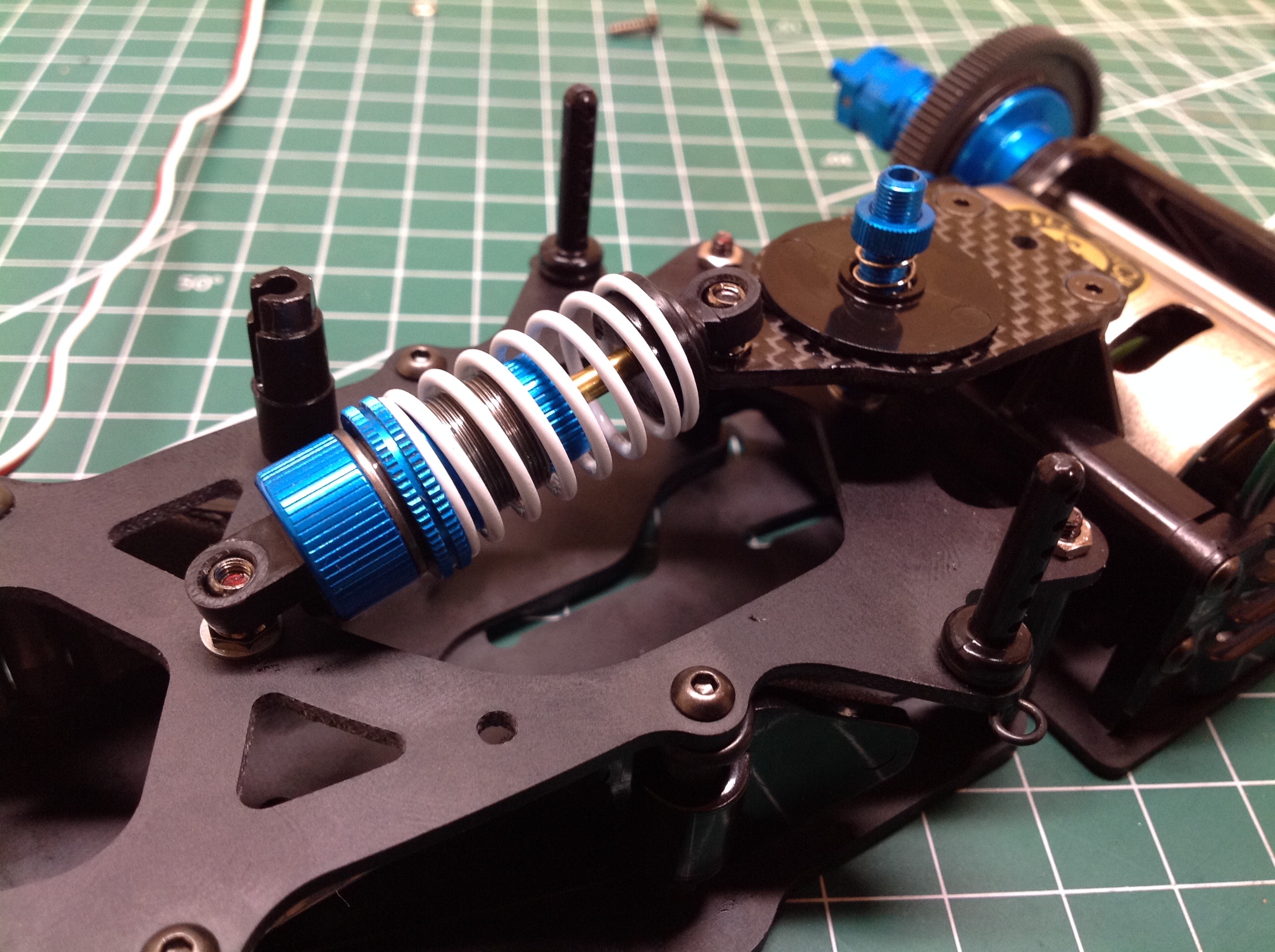
The rear suspension uses a single TRF oil shock. These beautiful shocks are always a joy to build. The only carbon part in the model is the slip plate shown. The plate is locked to the rear gearbox while the round discs are connected to the main chassis. As the rear end flexes, the carbon plate slides between the discs. The damping of the rear suspension can be adjusted by tightening or loosening the screw which clamps the discs.
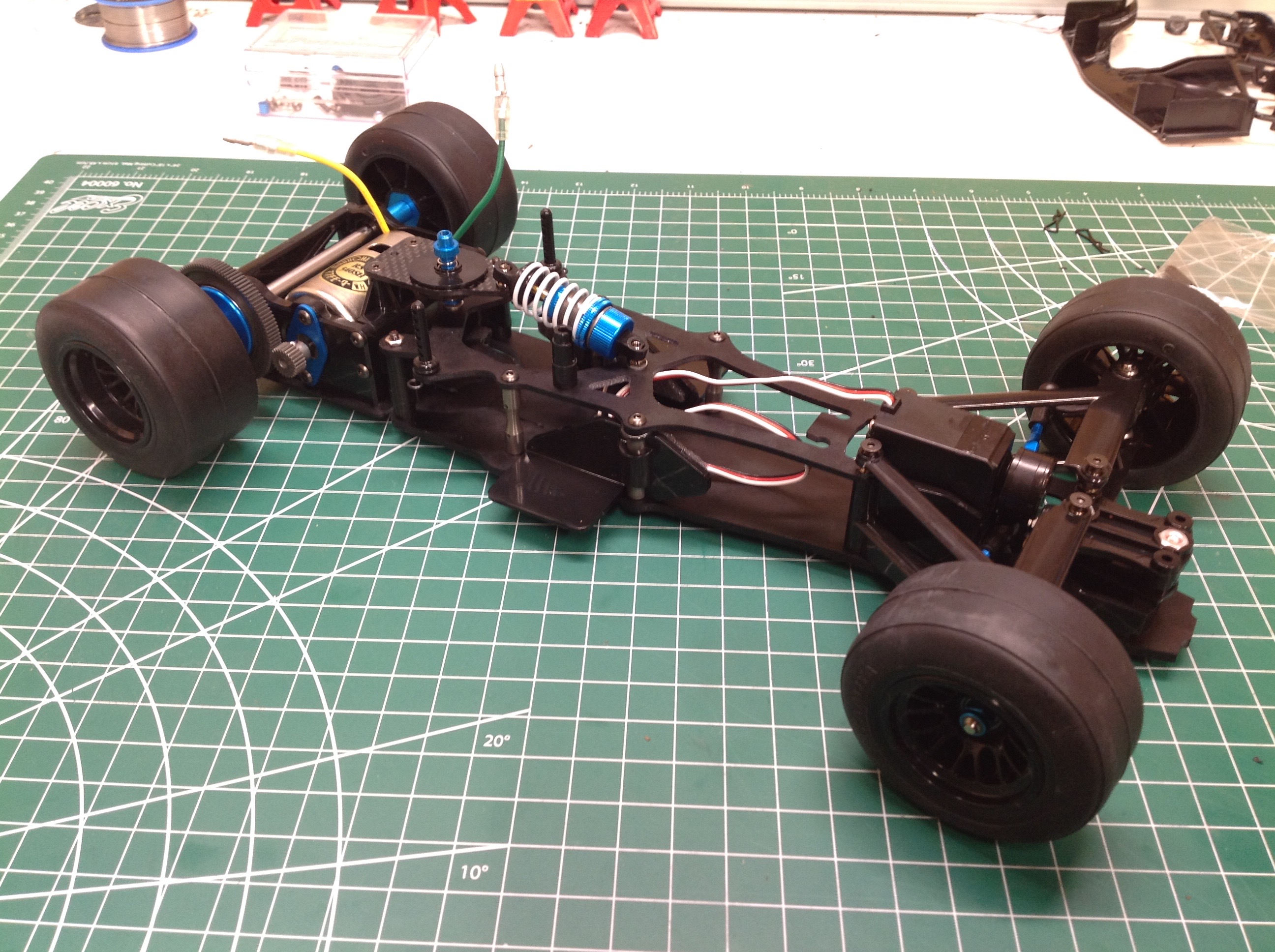
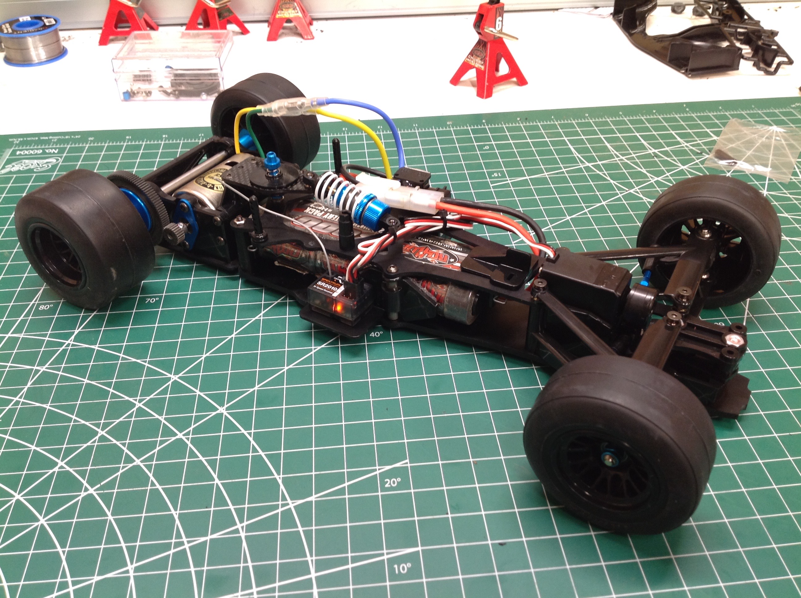
The tires do have to be glued to the wheels which is always my least favorite part of a build. These photos are taken before I painted the wheels or glued the tires. The electronics are installed on small plastic pods on either side of the chassis. These pods can pivot out of the way to allow insertion of a battery at an angle and then lock into place after the battery is straightened.
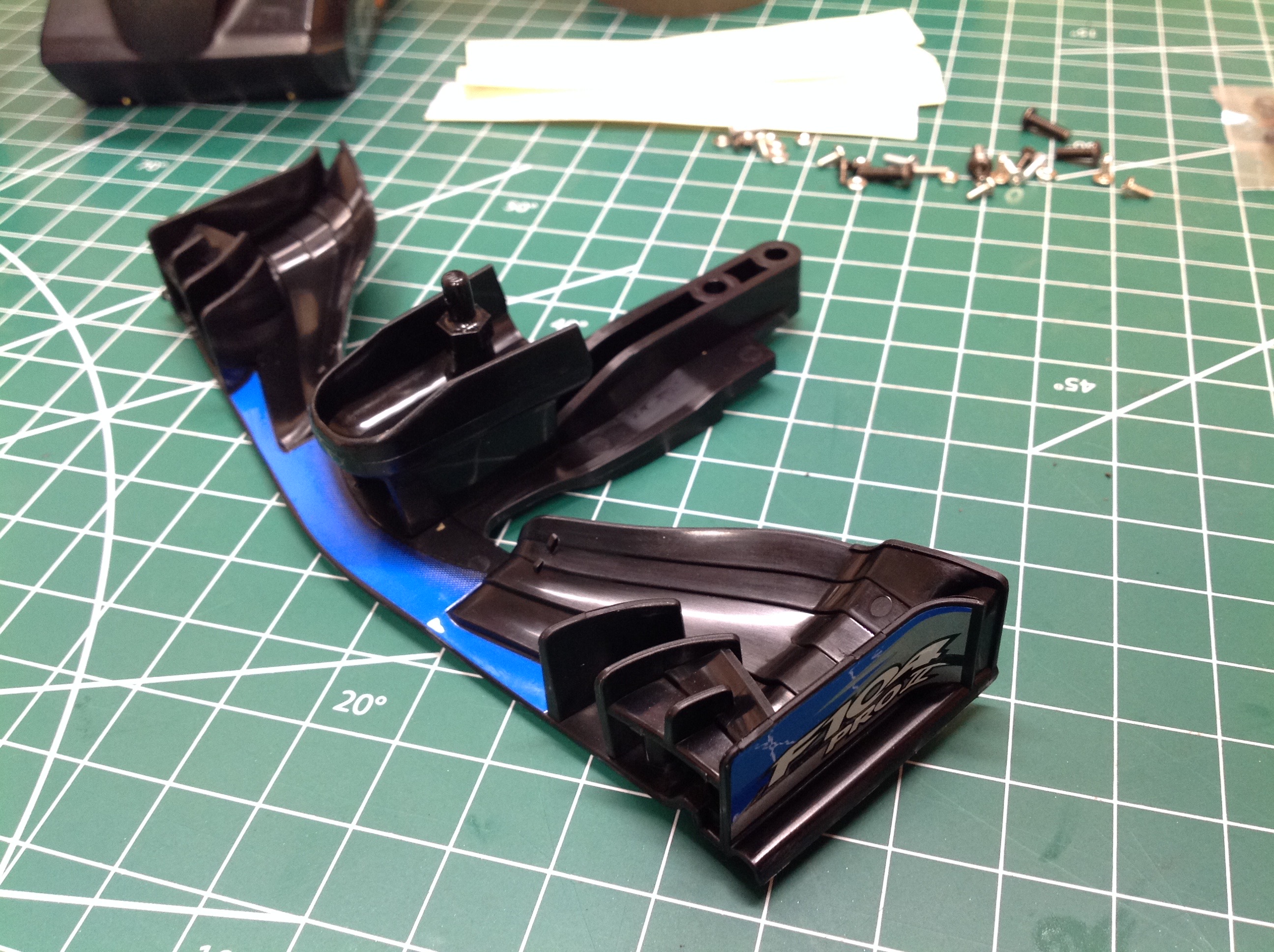
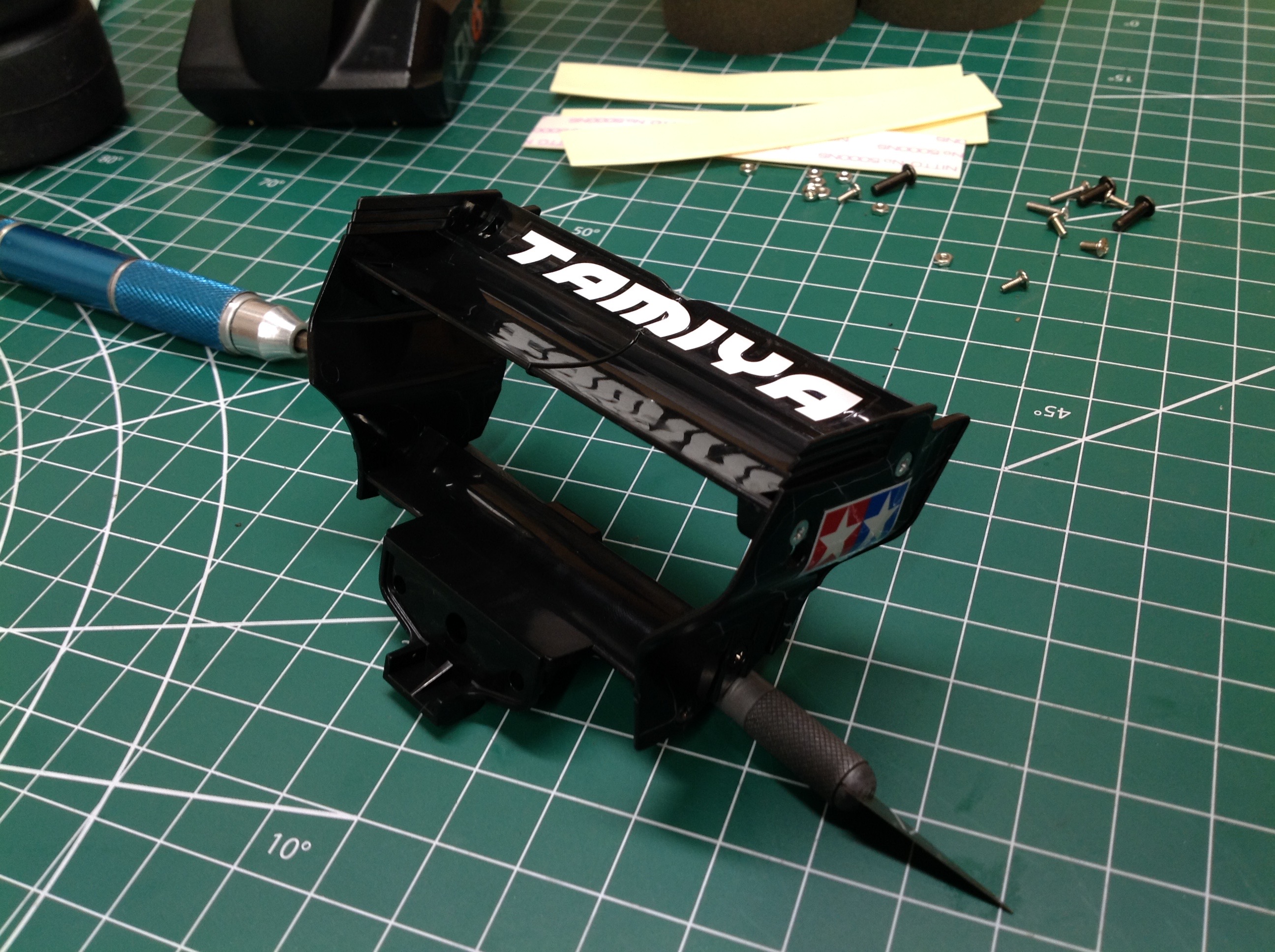
The front and rear wings are each made up of multiple parts and plenty of decorations. They are attached to the chassis rather than to the body.
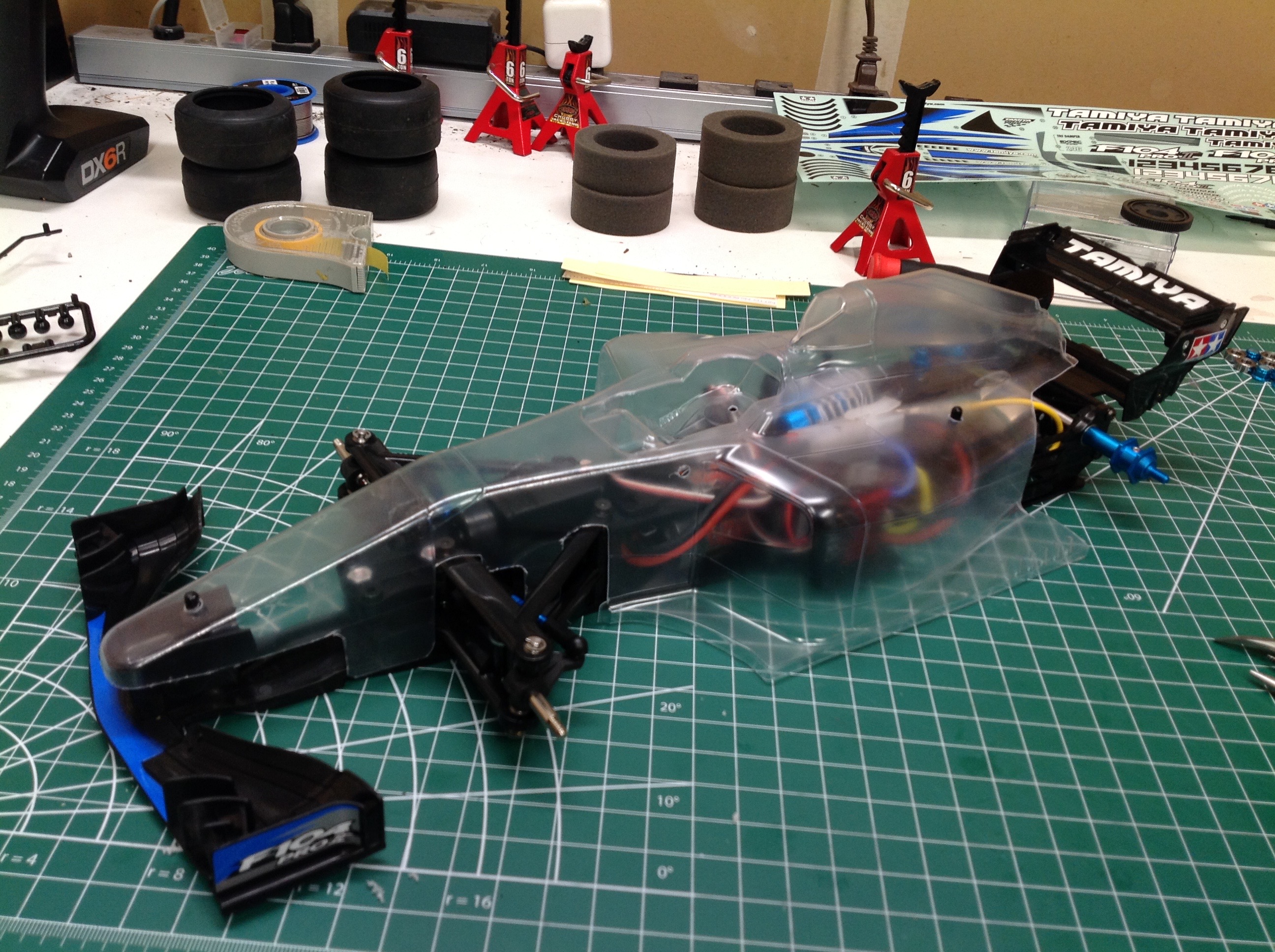
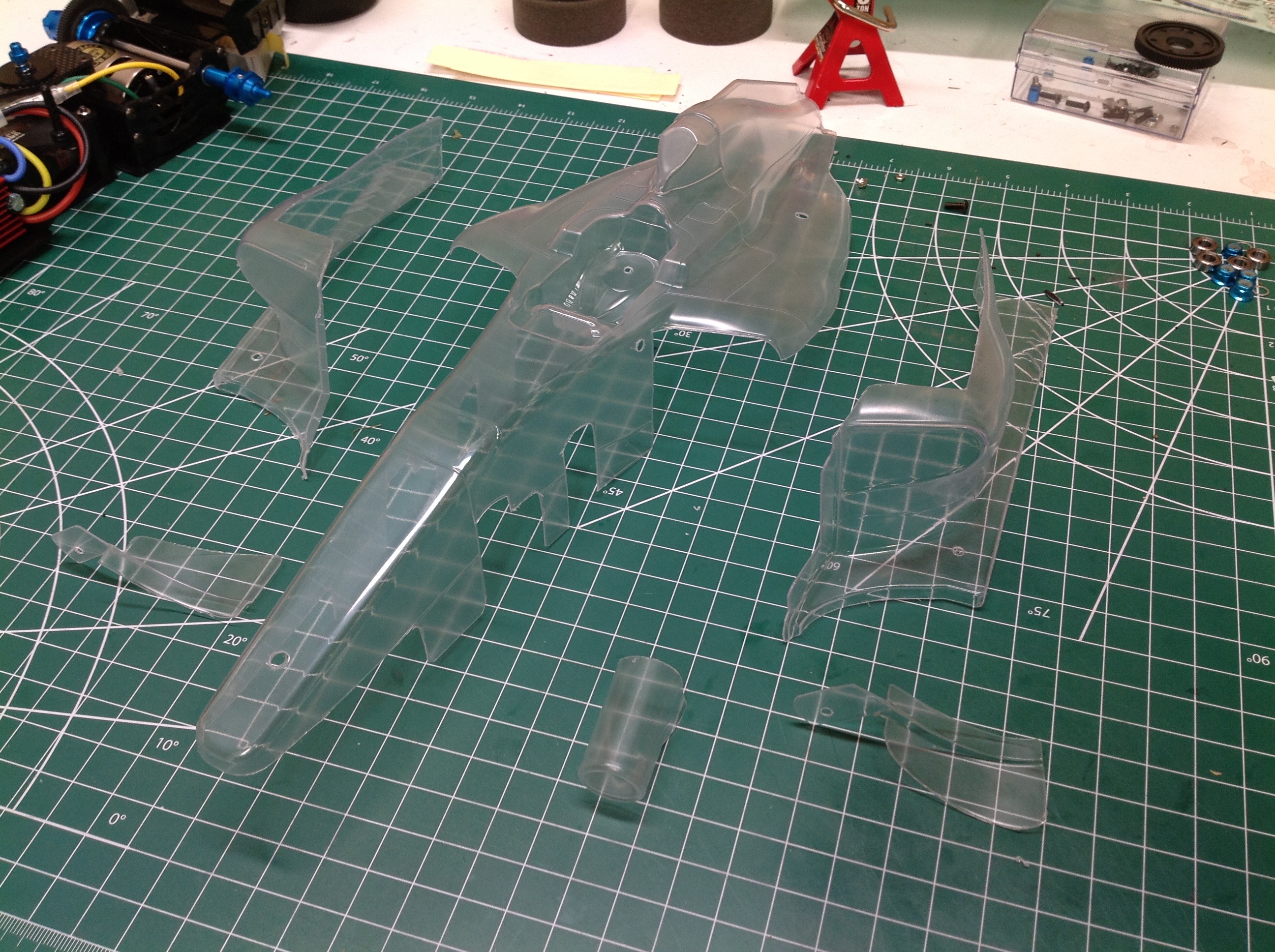
Now I can test fit the polycarbonate body. This is about as complex a PC body as I have ever seen. Apart from the main section, there are separate side pods, strakes, and an air inlet as well as a plastic driver's head and other aerodynamic bits. It is possible to build the body without the extra side pods, but then they won't curve under at the bottom like they should. It is impossible to have an undercut angle with a vacuum form.
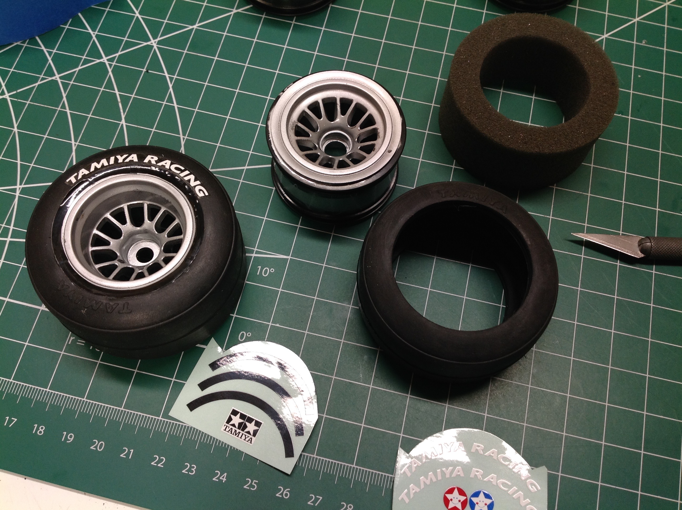
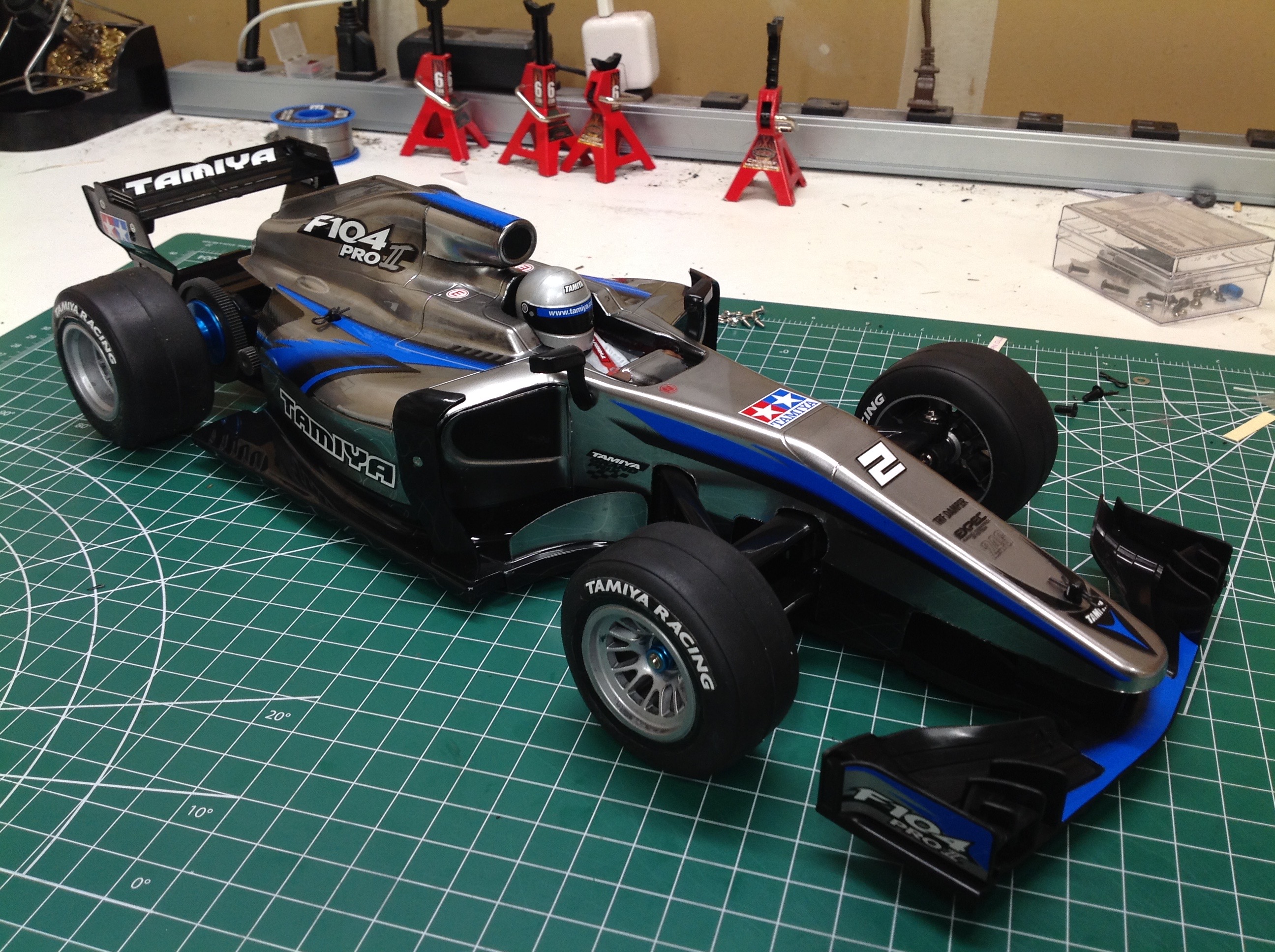
Now that the wheels are painted (I masked the bead), the tires can be glued on and the stickers applied. It is really important to wash and clean the wheels if you want anything to stick. I used soap and then rubbing alcohol which worked great. The completed model is shown on the right.
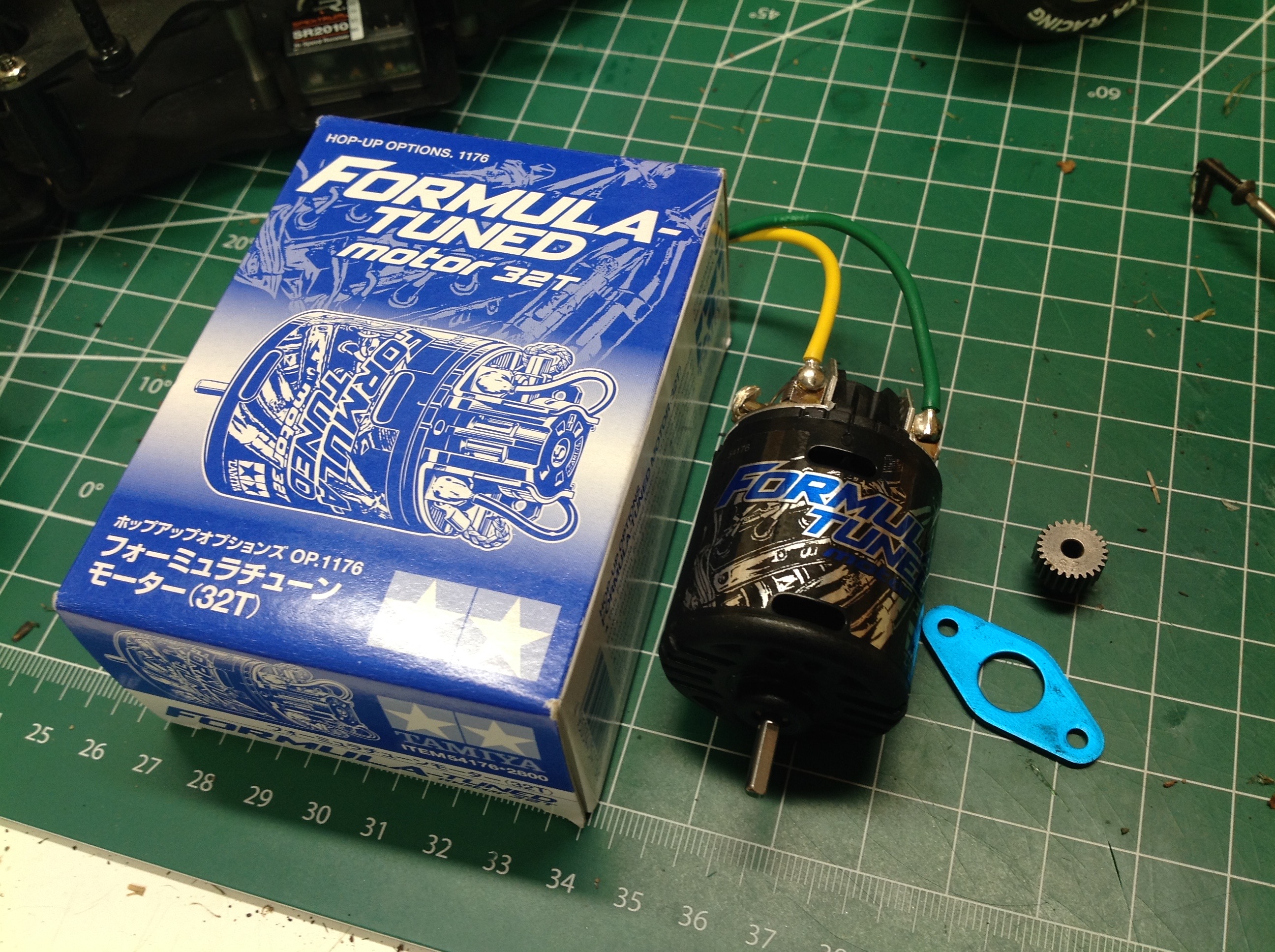
I installed the Formula Tuned motor as soon as it arrived, but not before trying out the basic silver can first. You might expect that a 32T Formula Tuned motor would actually be slower than a 27T silver can, but it didn't turn out that way. It is slightly faster and also accelerates better, though it also spins out more easily.