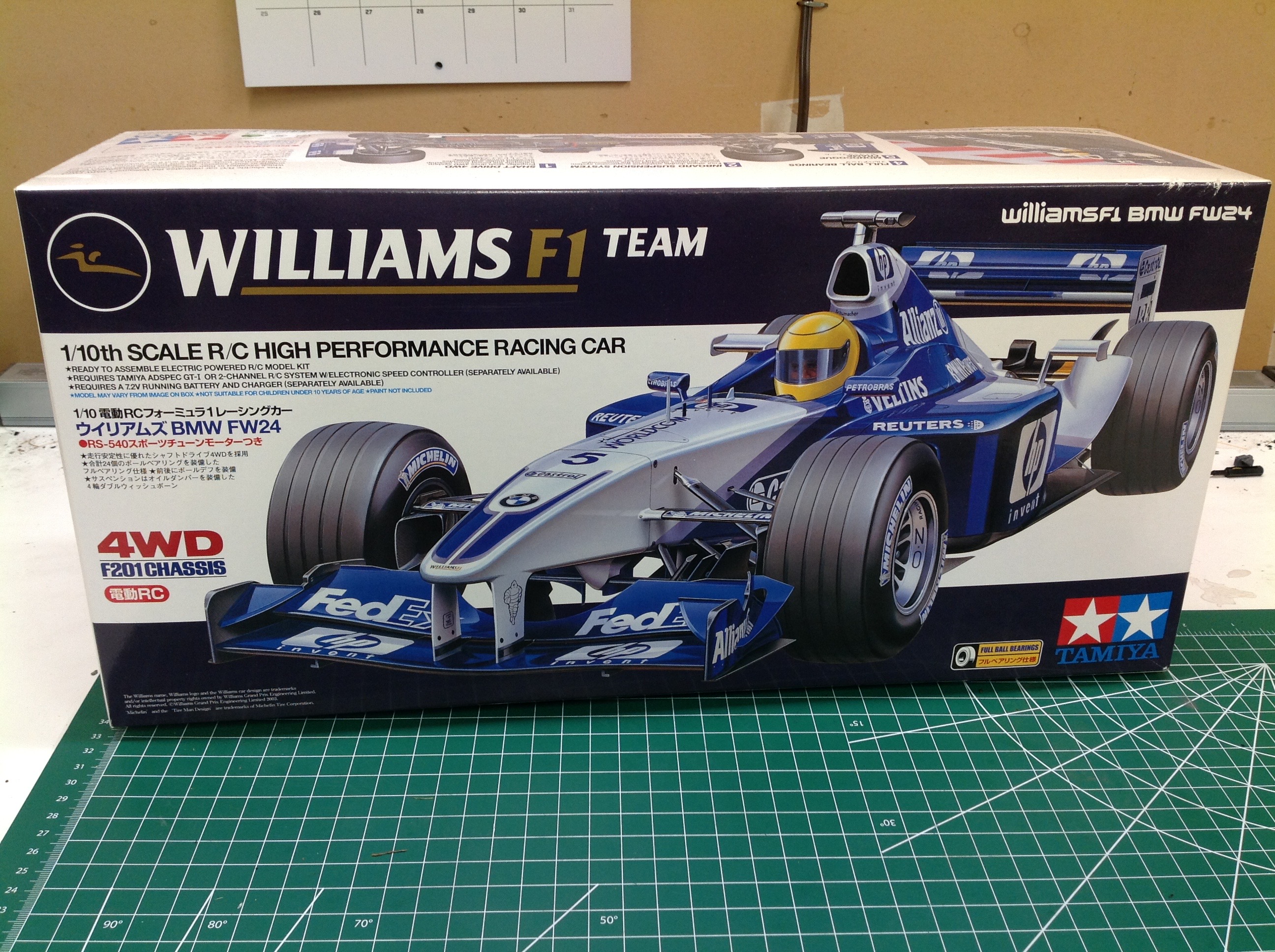
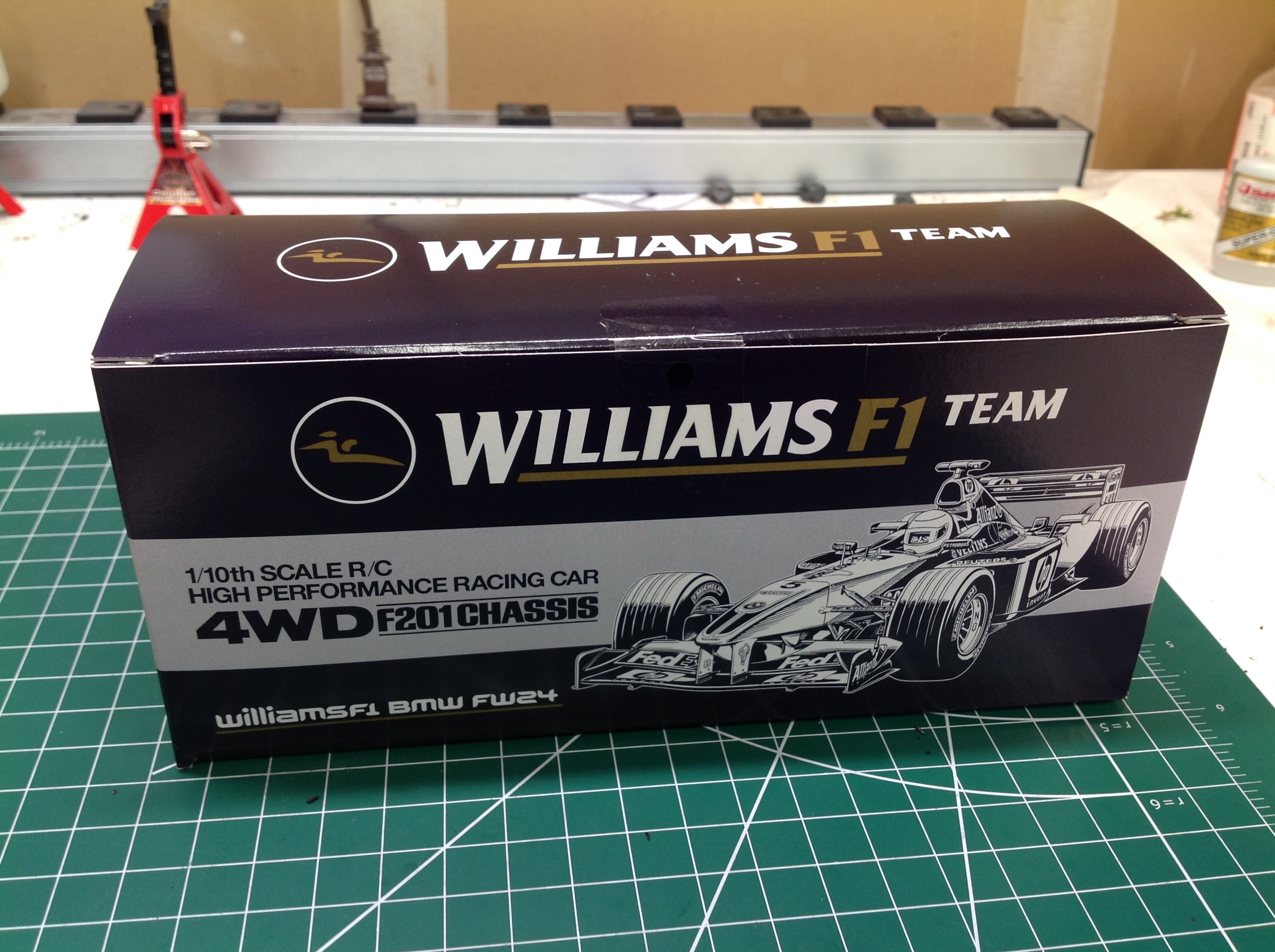
The Williams comes in a small but tightly packed box. All of the hardware is contained in a smaller inner box shown on the right.
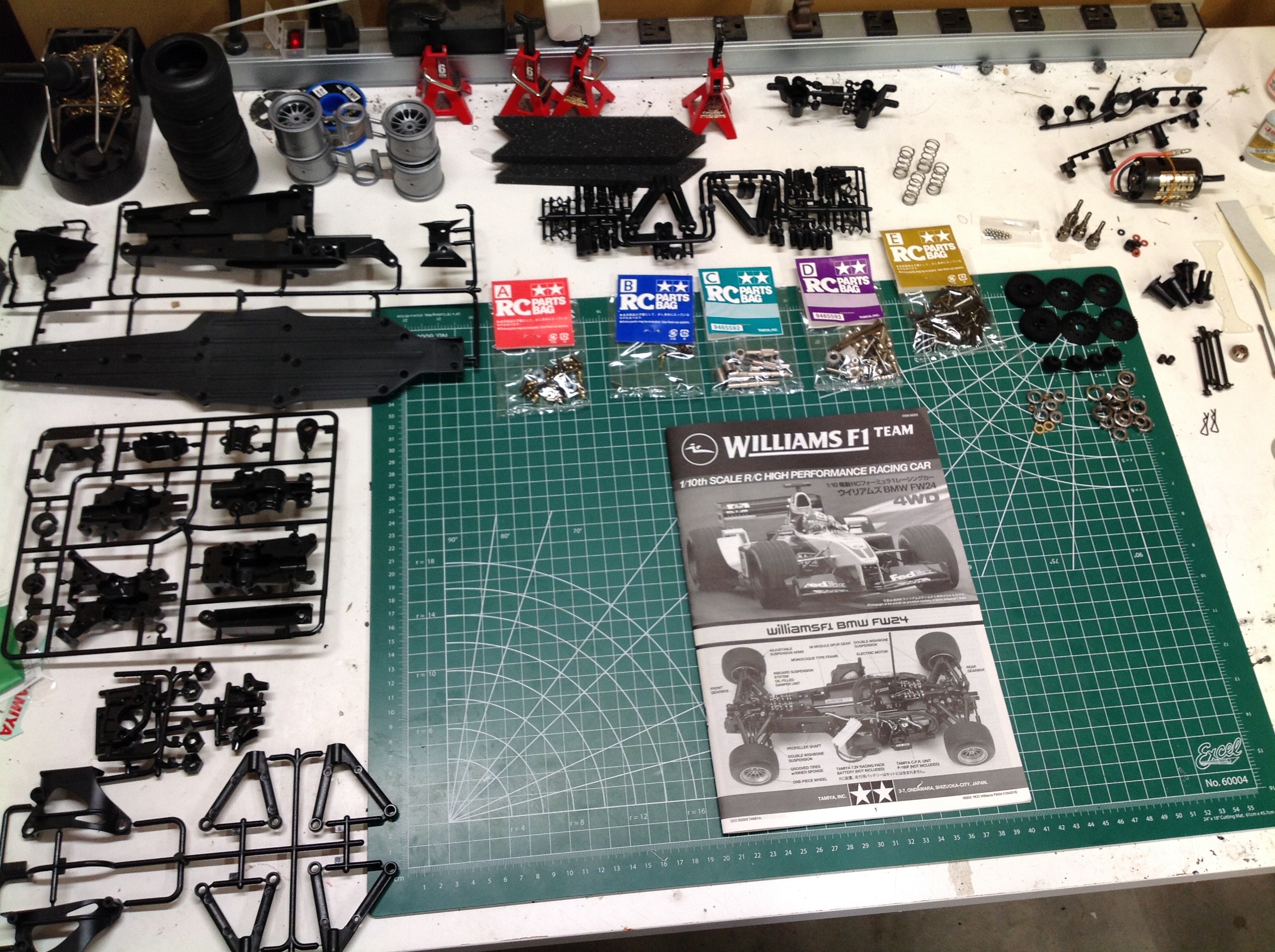
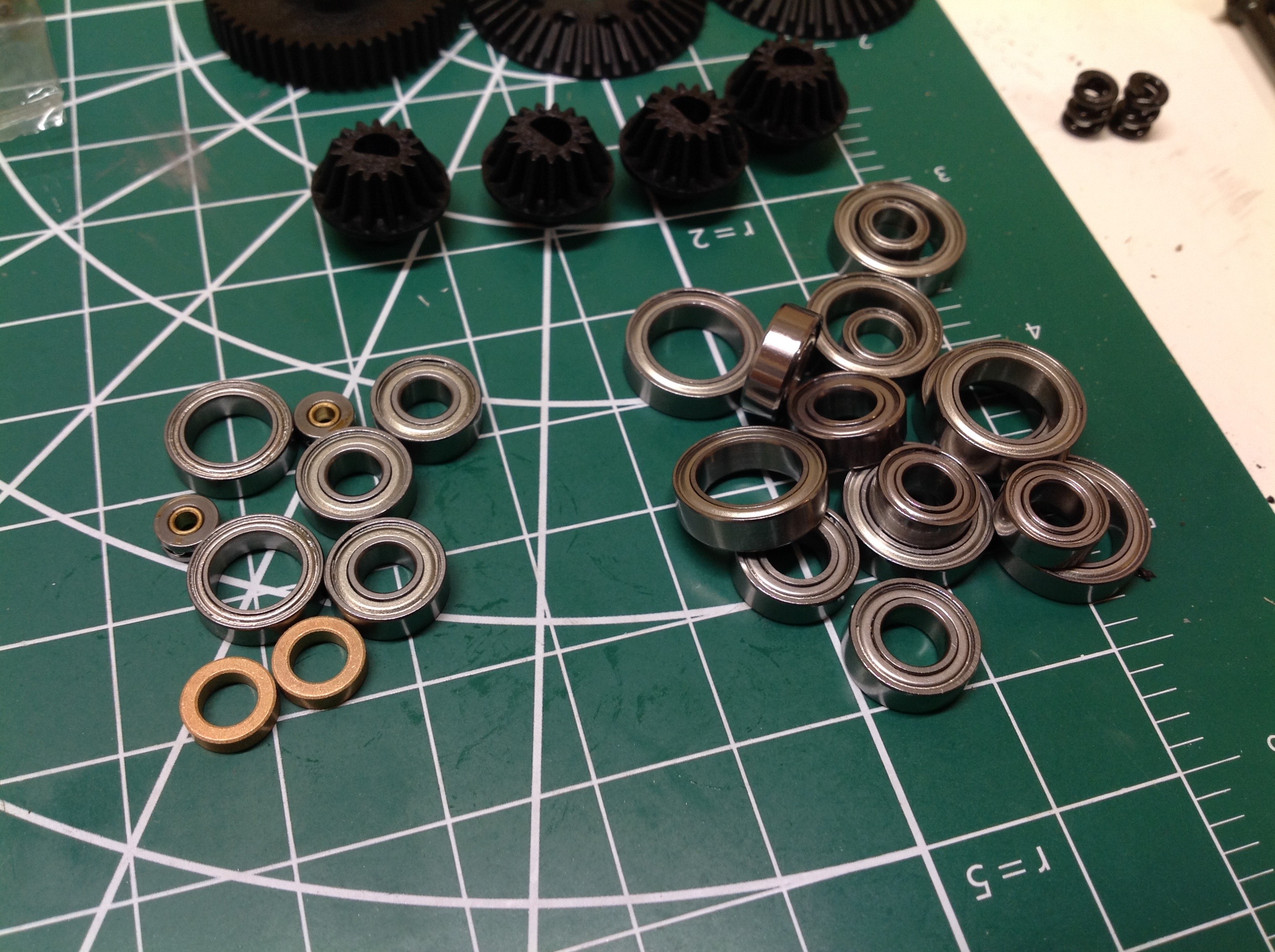
The F201 has vastly more parts than the typical and simple rear wheel drive F1 chassis. The kit comes with a full set of ball bearings as well. The pair of metal bushings you see are for the steering cranks, not for axles.
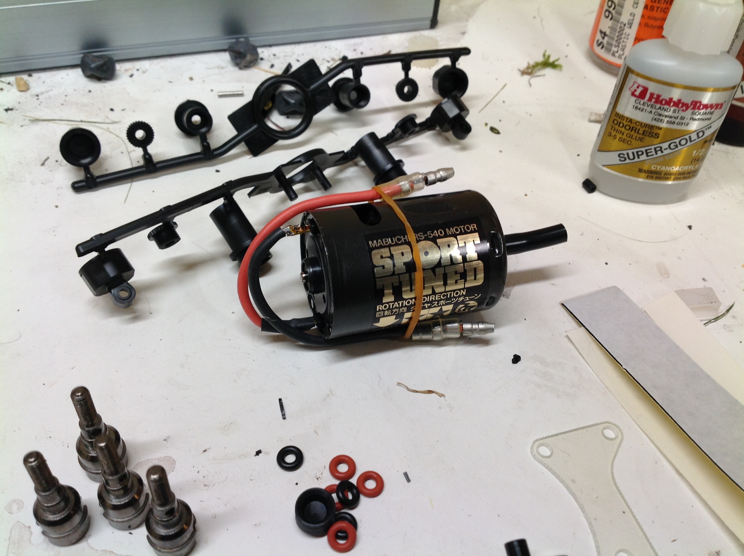
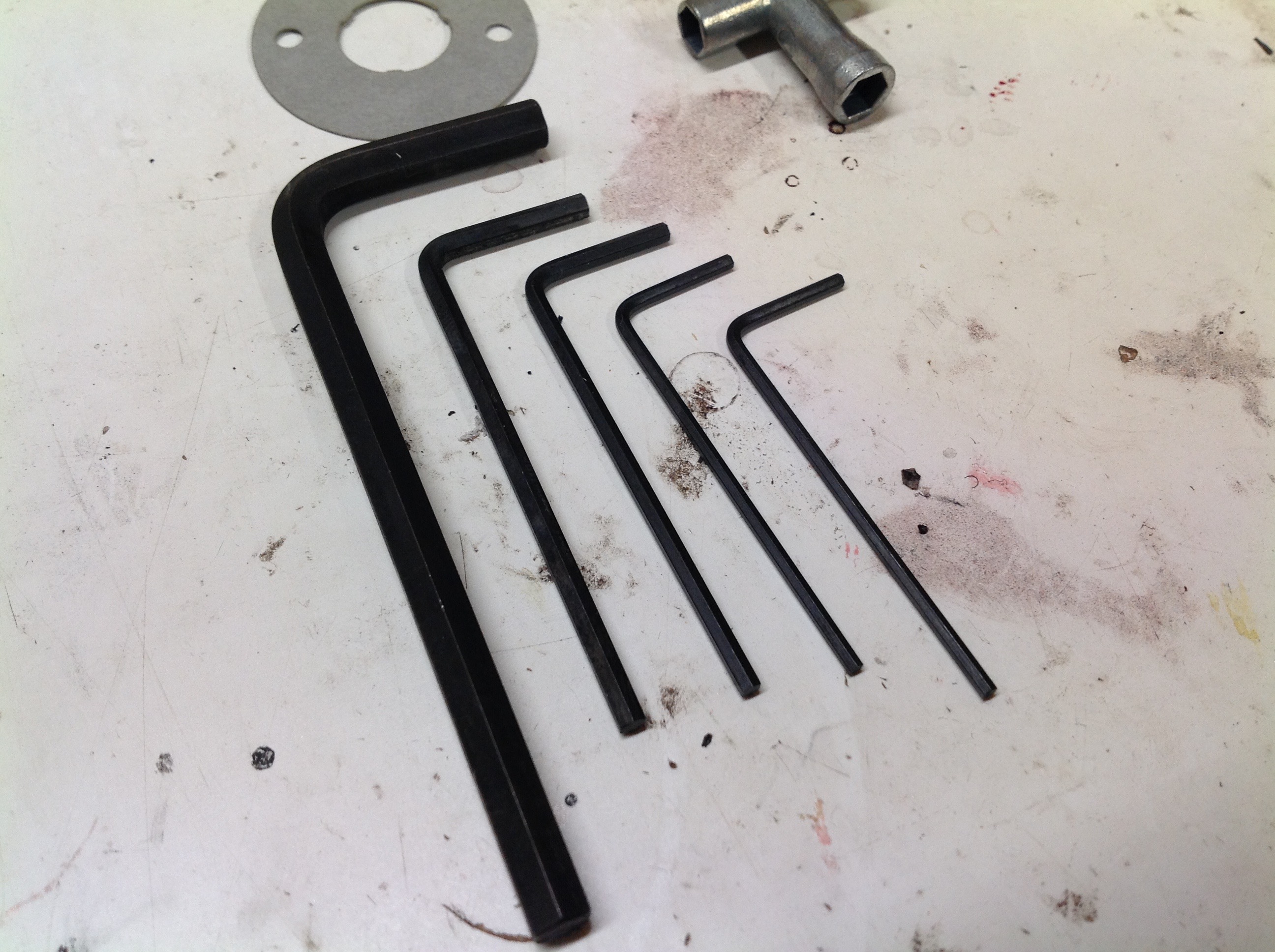
This kit comes with the 23 turn Sport Tuned motor which is good for a bit of extra speed (though not much) compared to a stock silver can. There's also an unusually large assortment of hex keys. Most Tamiya kits come with a 1.5mm and a 2mm key, but this adds another 1.5mm, a 2.5mm, and a huge 4mm key. The pair of 1.5mm keys are required to tighten two parts against each other, and the 4mm key is used to adjust the pillow balls.
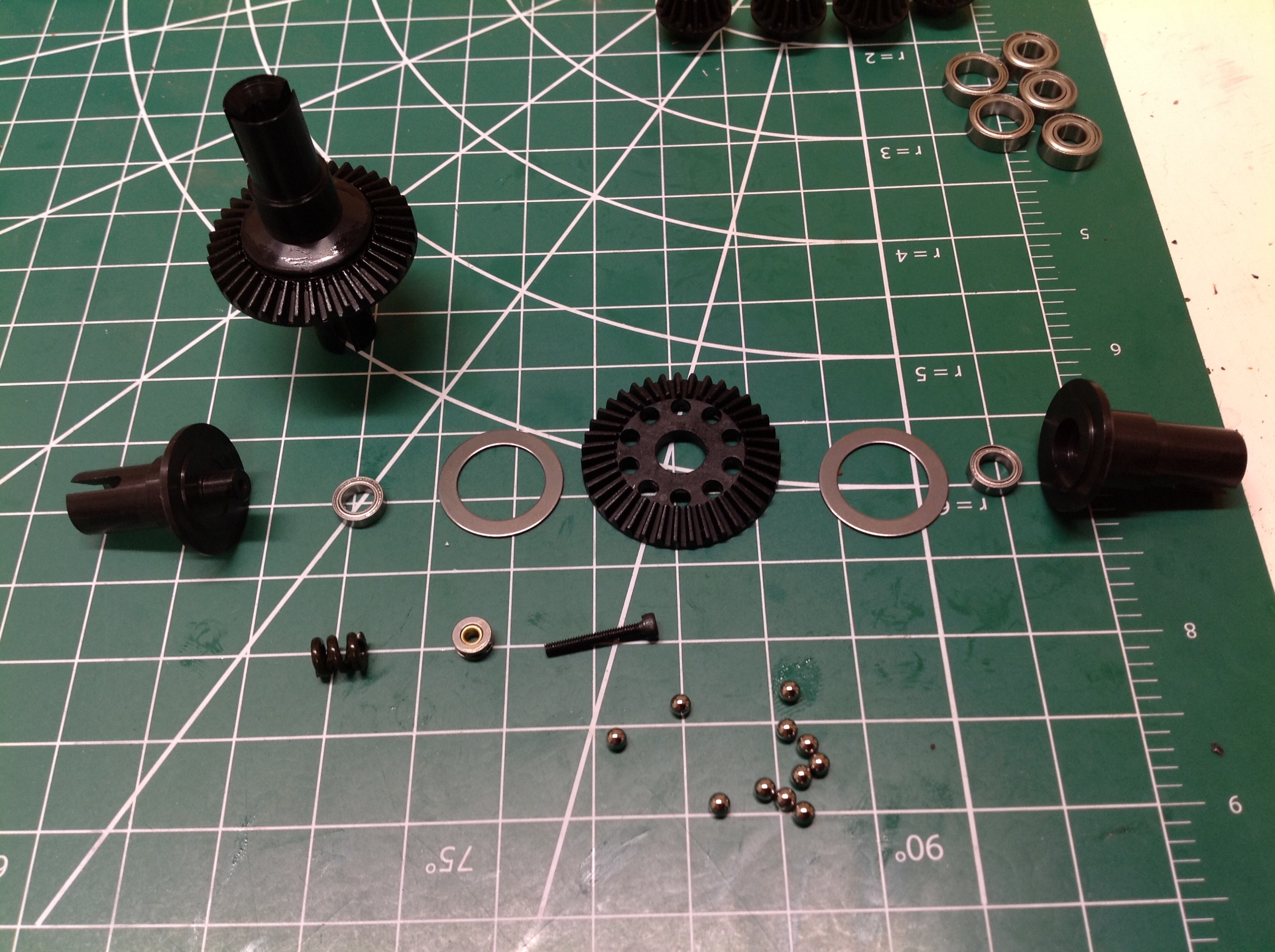
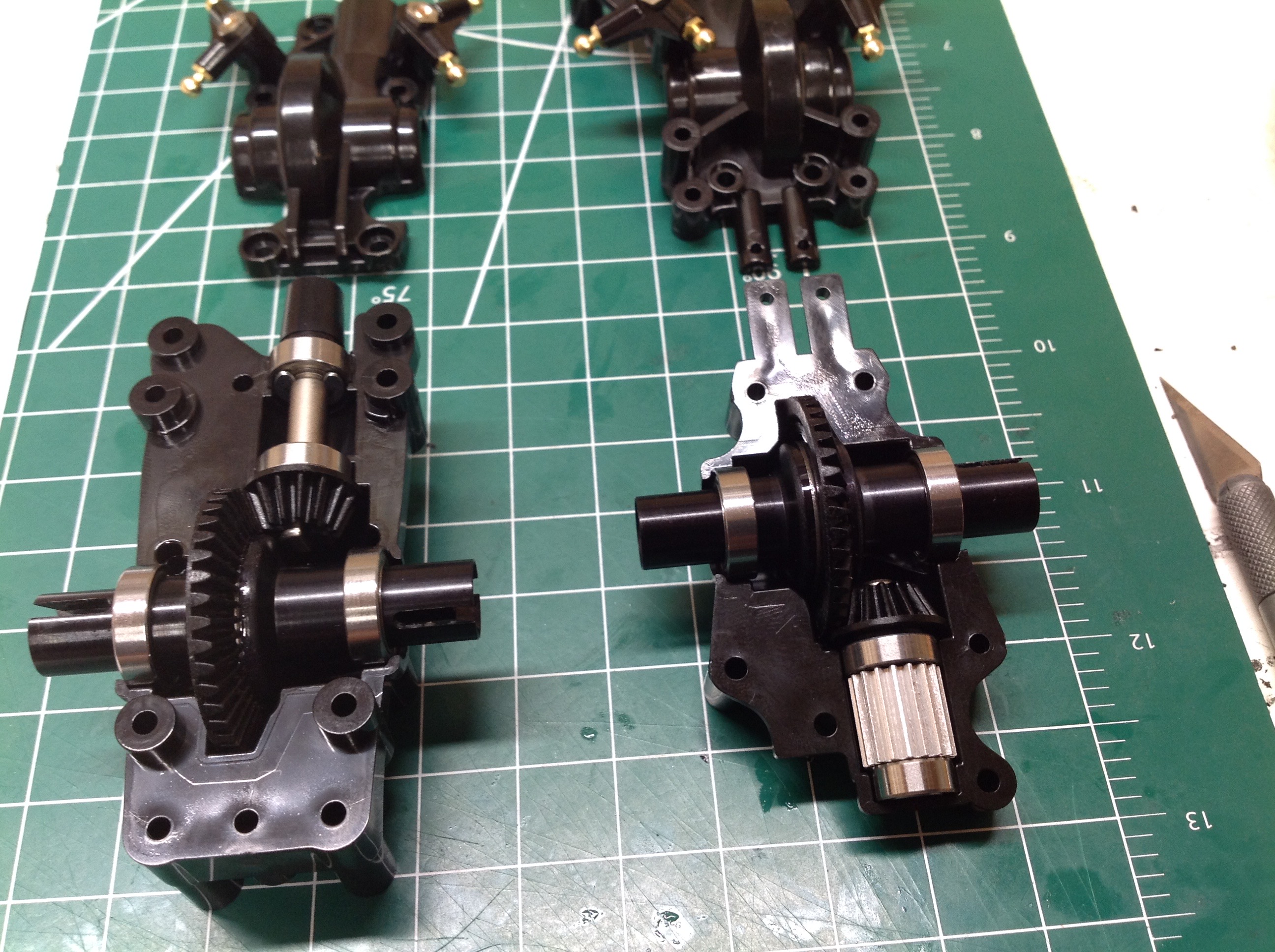
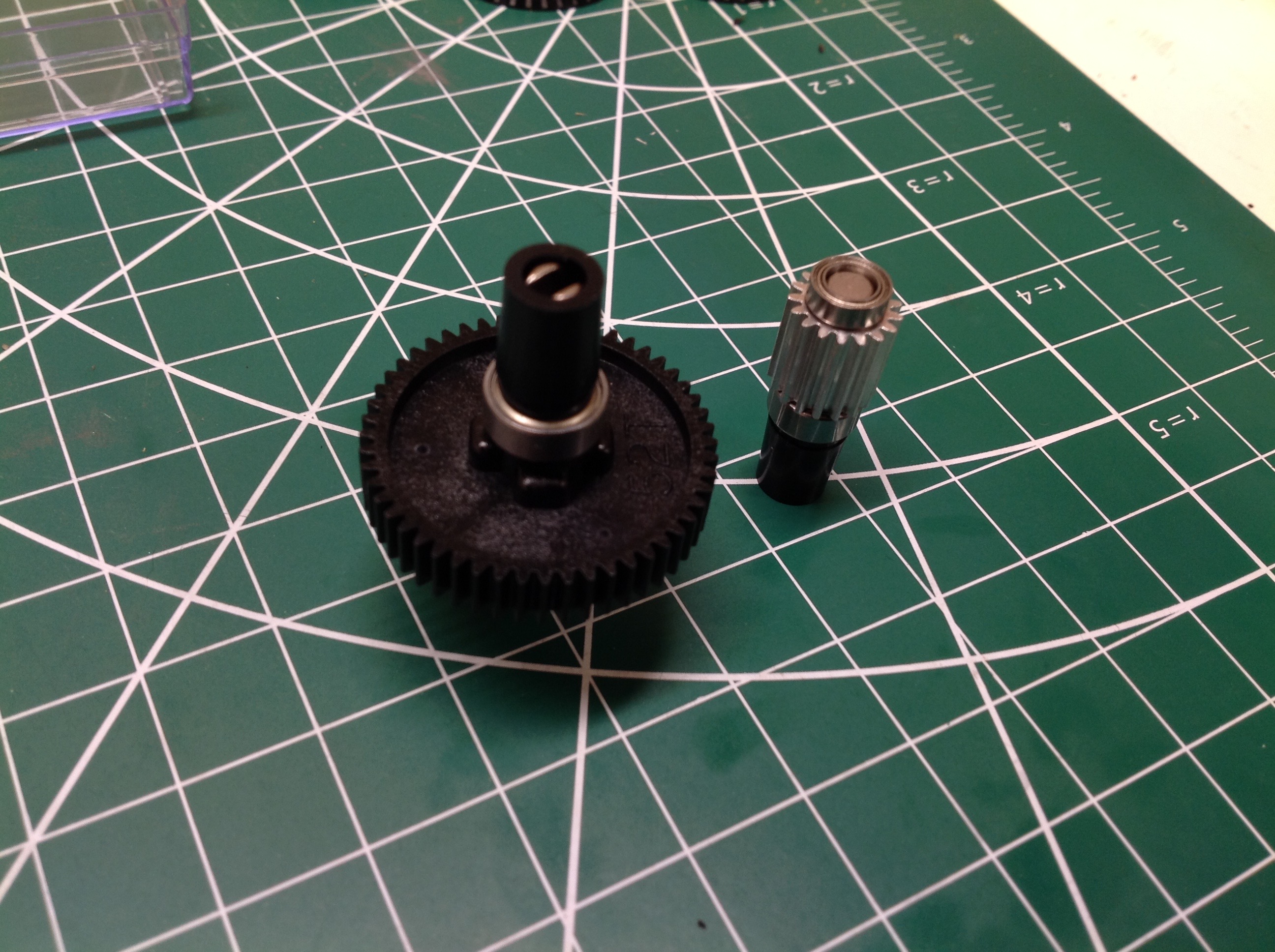
The front and rear gearboxes use ball differentials which are then installed into the housings and driven by bevel pinion gears. The rear gearbox has an additional aluminum spur gear which will connect to the motor drive system.
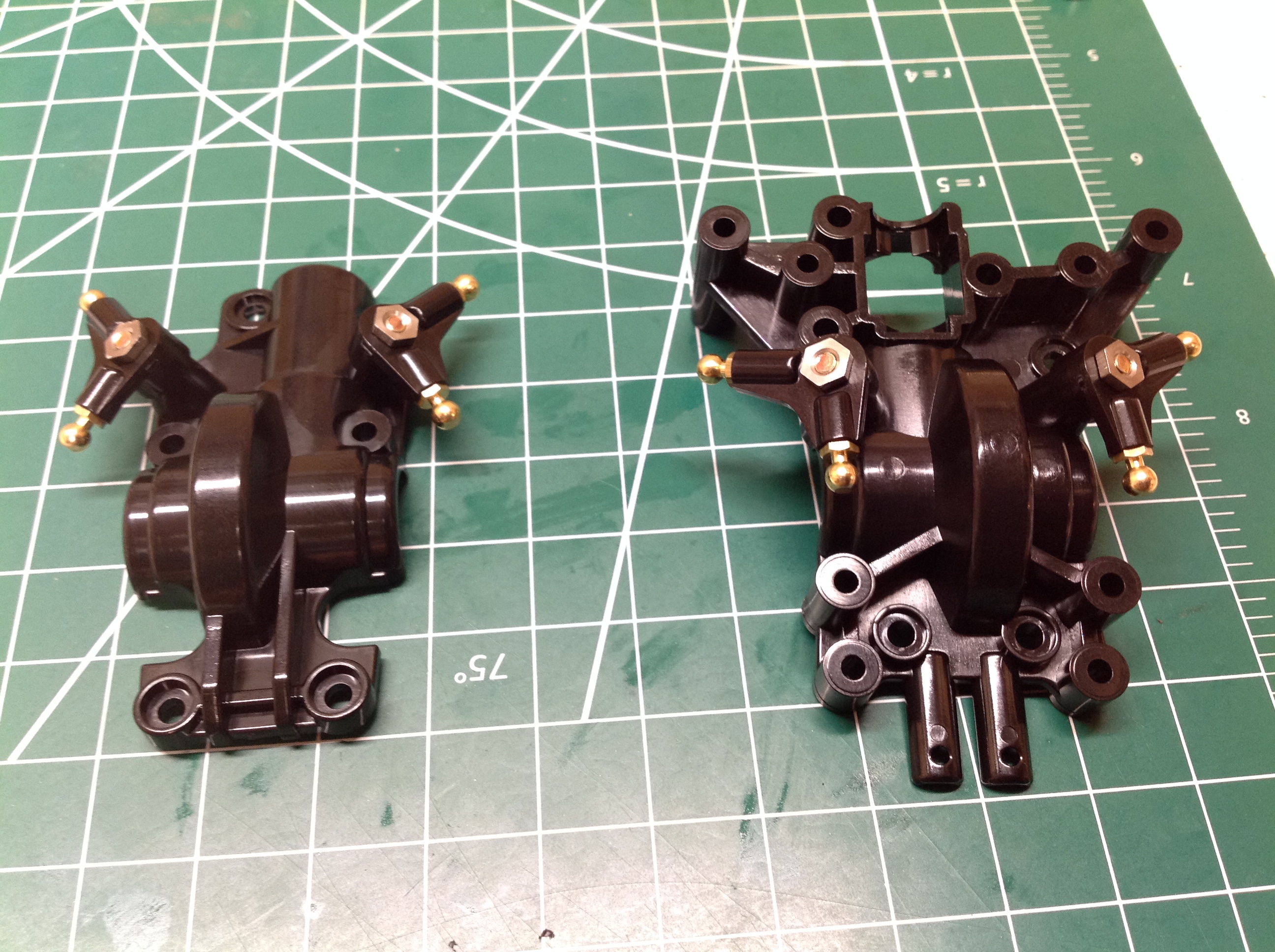
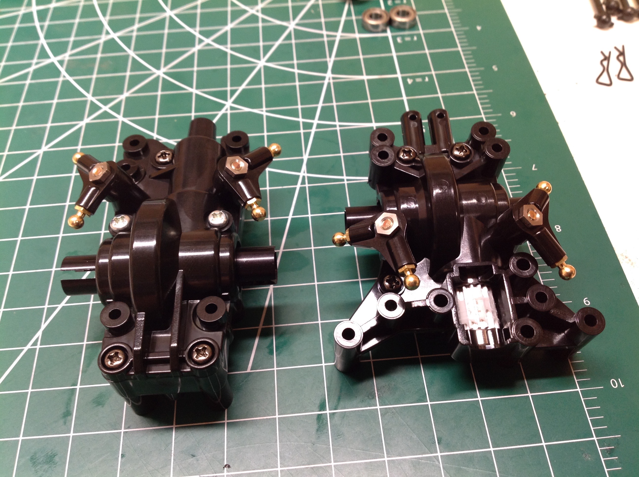
The cranks which sit at an angle atop the gearbox housings convert the vertical motion of the suspension rods to longitudinal motion at the shocks. This leads to pretty complex looking gearboxes based on the the outer profile, but they are simpler than they appear.
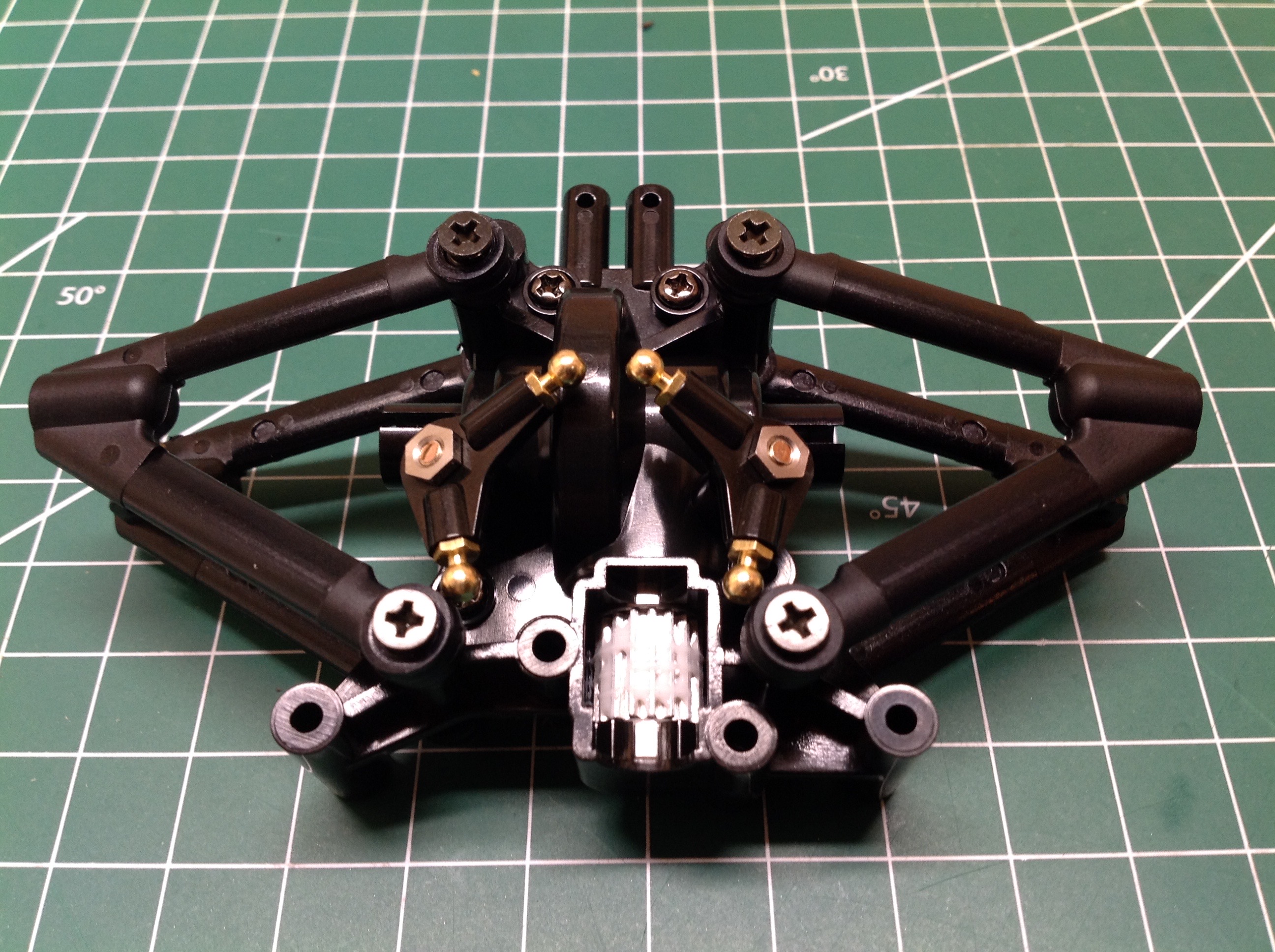
Here's the rear suspension. The suspension arms are pinned wishbones: upper and lower. The balls are threaded directly onto the bulkhead. The screws you see sticking out the top are there to prevent the arm from popping off the ball.
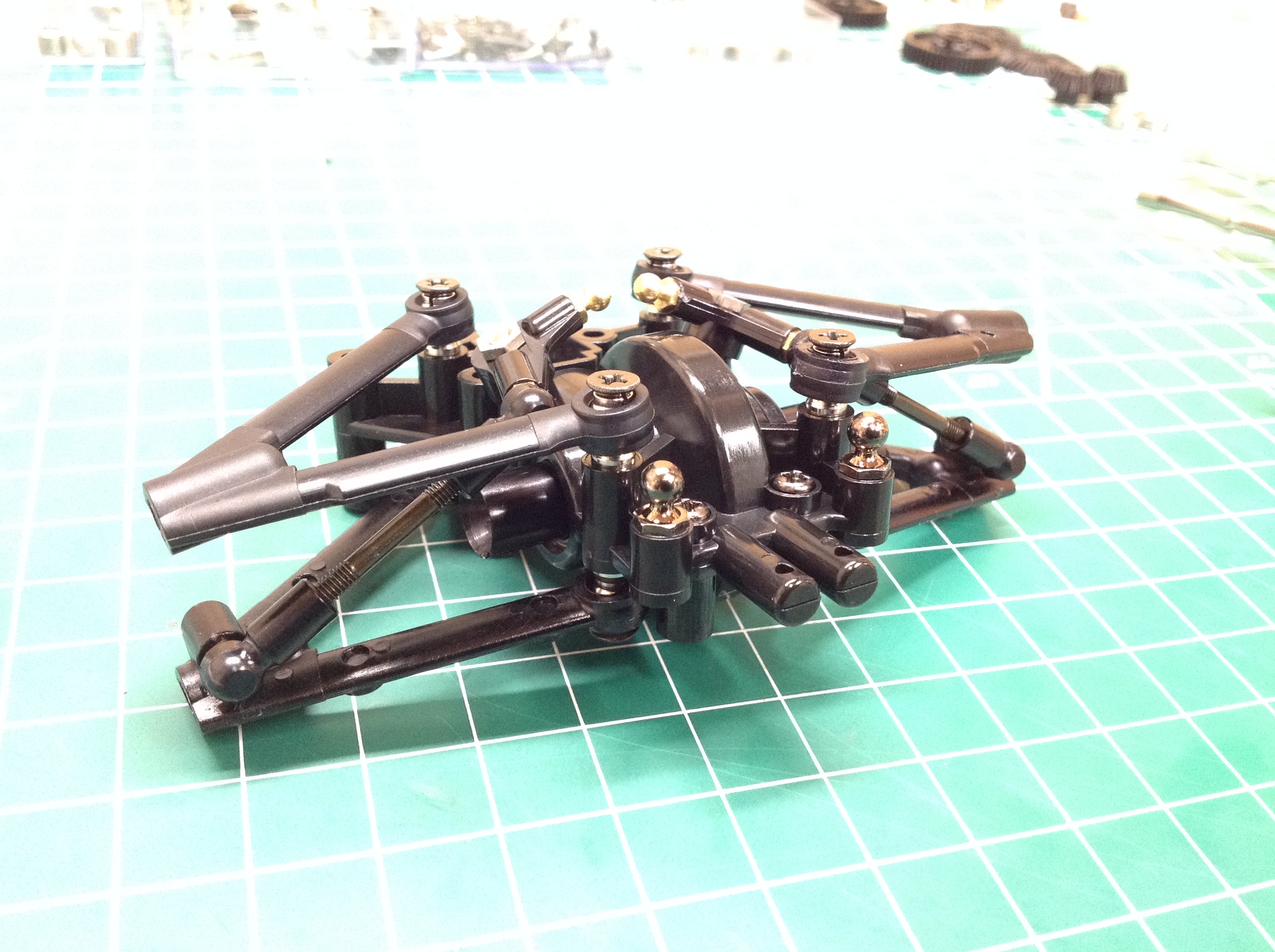
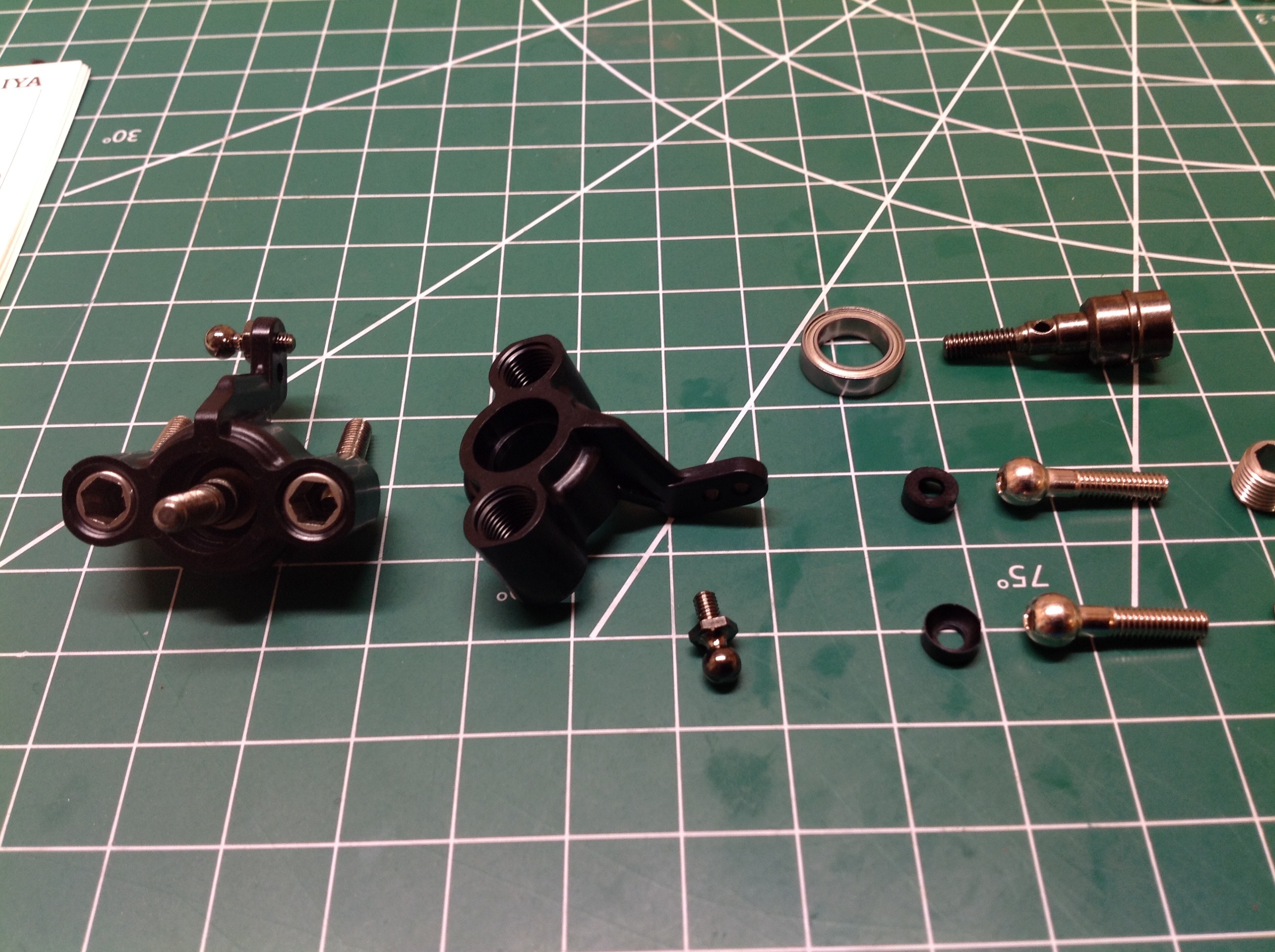
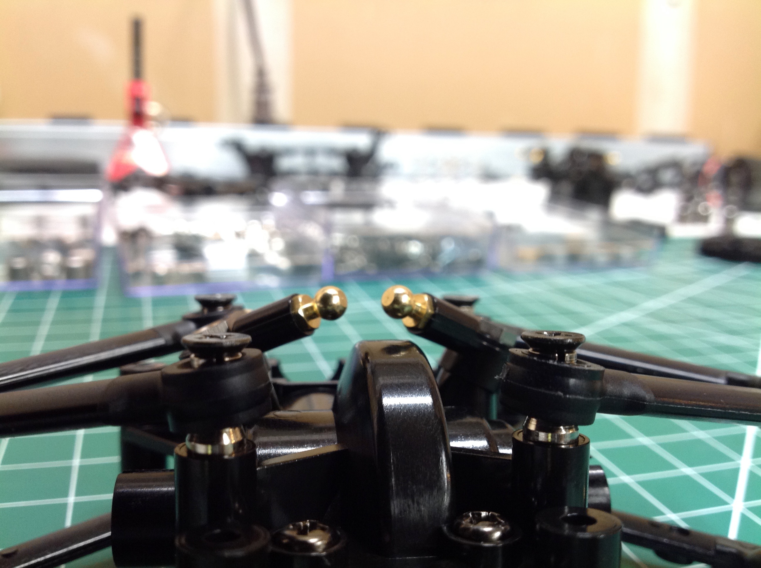
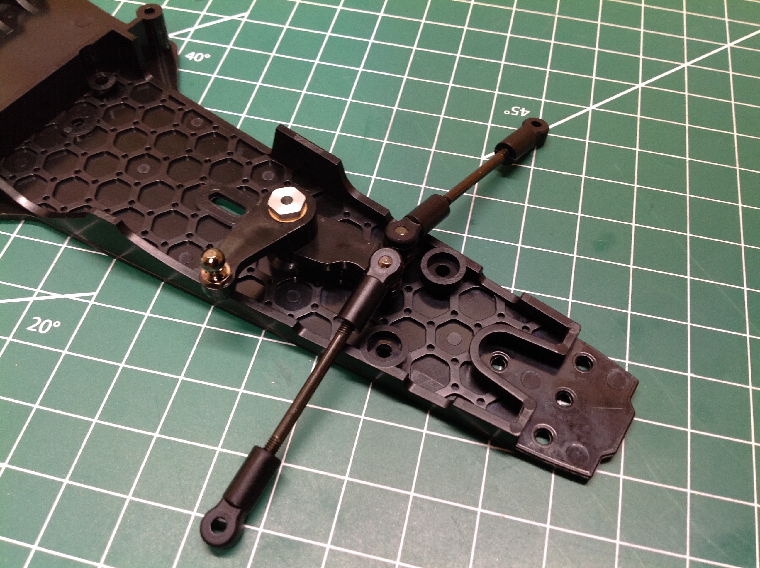
The pushrod which drives the shocks attaches at the outboard end of the lower arm and diagonally connects to the crank arm at the upper inboard end as shown at left. At right you can see the upright which uses pillow balls to allow both suspension travel and toe on the same joint. A single ball is attached at each upper and lower arm which inserts through the upright. The 4mm hex slot is used to adjust the ball seat in and out which controls the tightness of the joint. This is the only Tamiya chassis I've seen to use Pivot Ball Suspension.
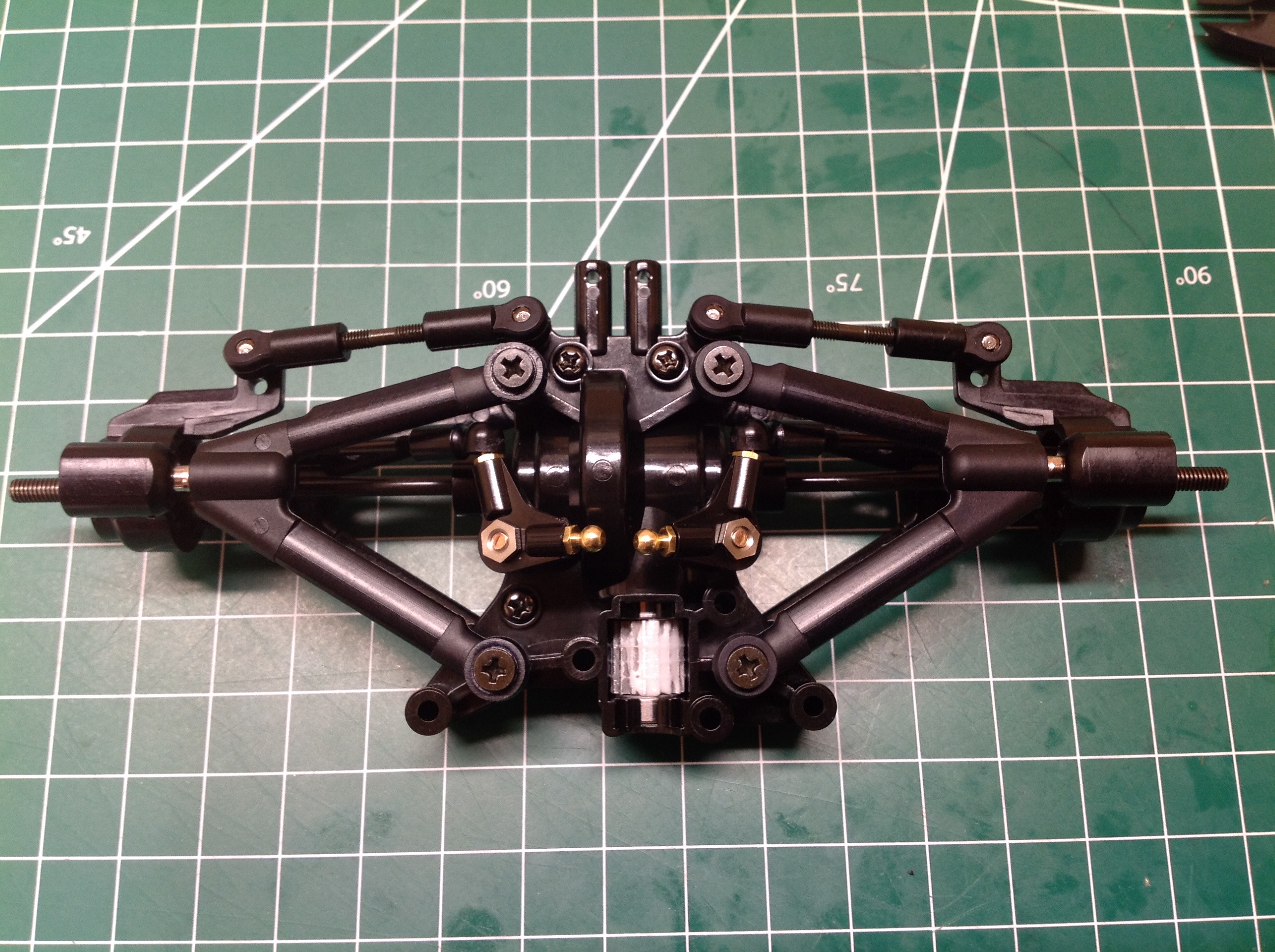
To complete the rear suspension we install the pivot balls and the toe links (seen at the very rear). These can be adjusted to control the toe angle which, by default, is slightly toed in at the rear.
The steering uses a single crank which pivots about the chassis base. This is the only part of the build that doesn't use ball bearings for a rotating part.
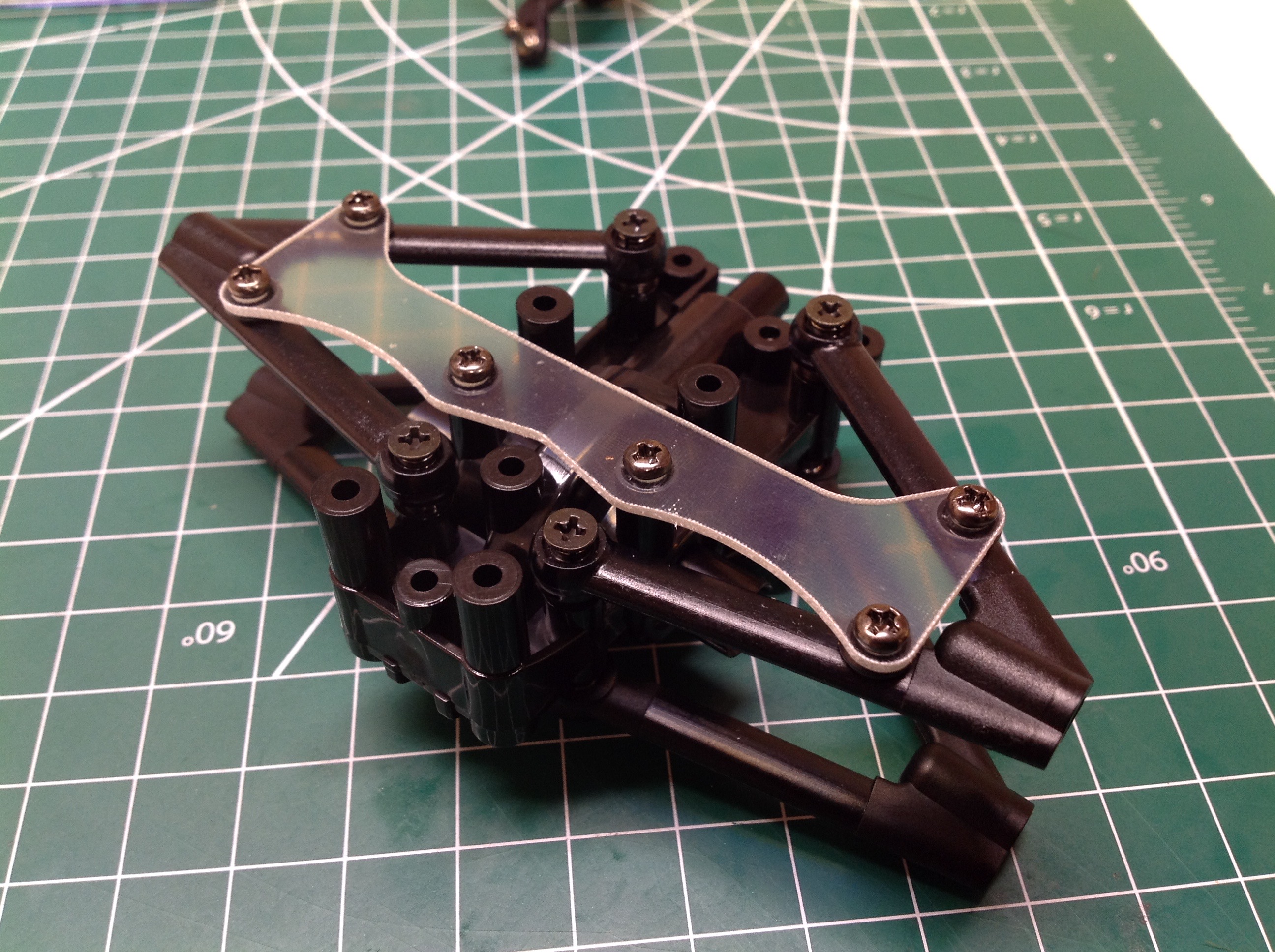
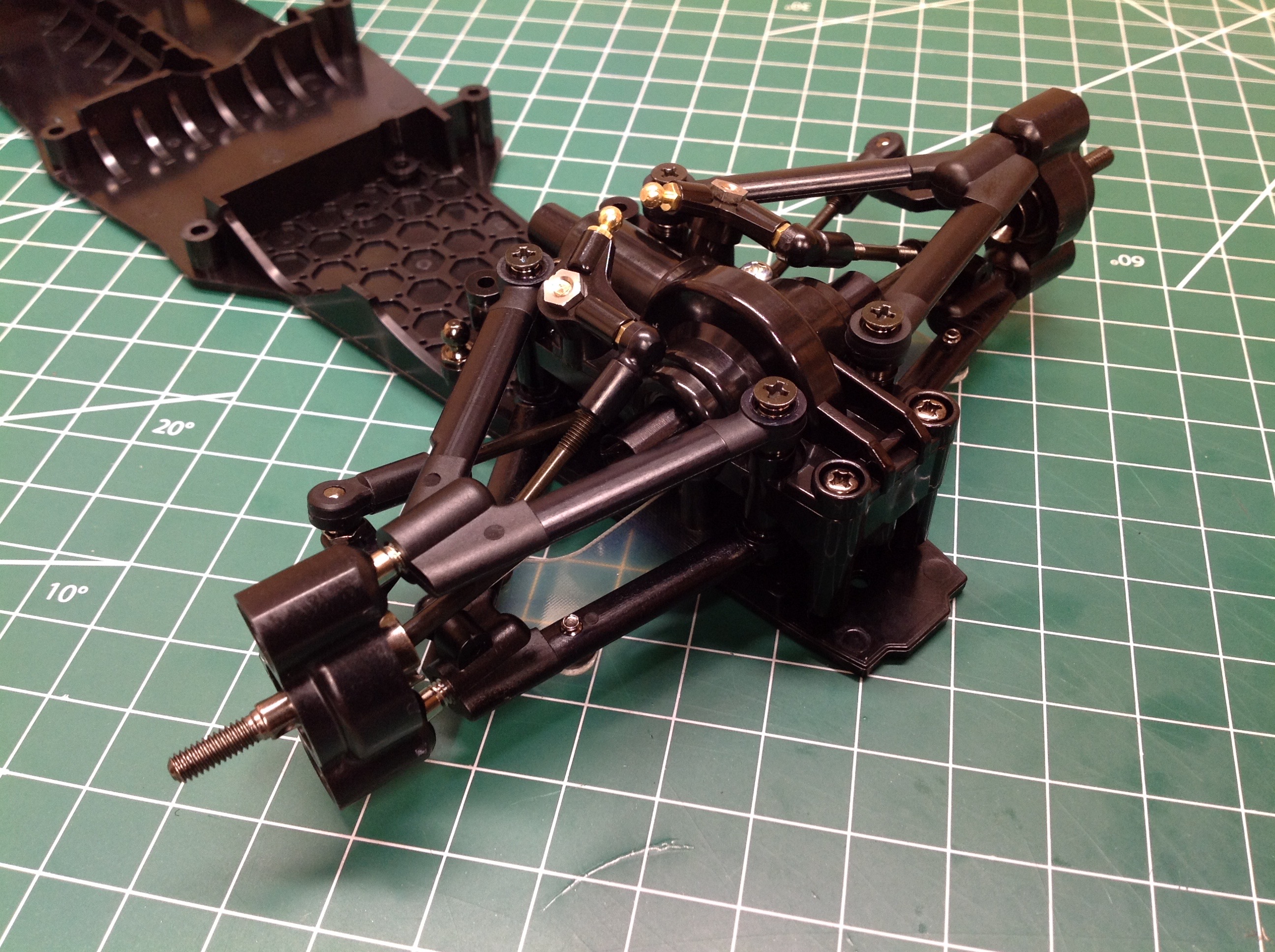
The front suspension uses this transparent FRP plate under the lower arms as an anti-sway stabilizer. It also serves to greatly stiffen the front suspension. The completed front end is shown on the right.
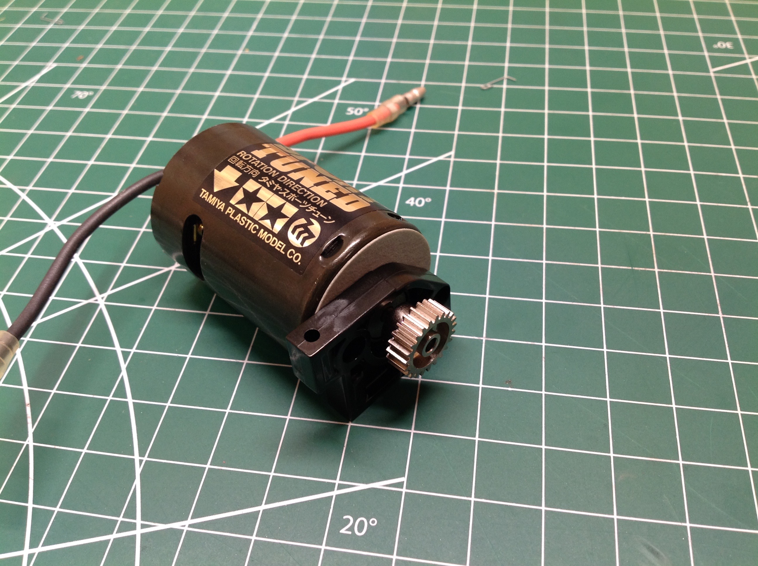
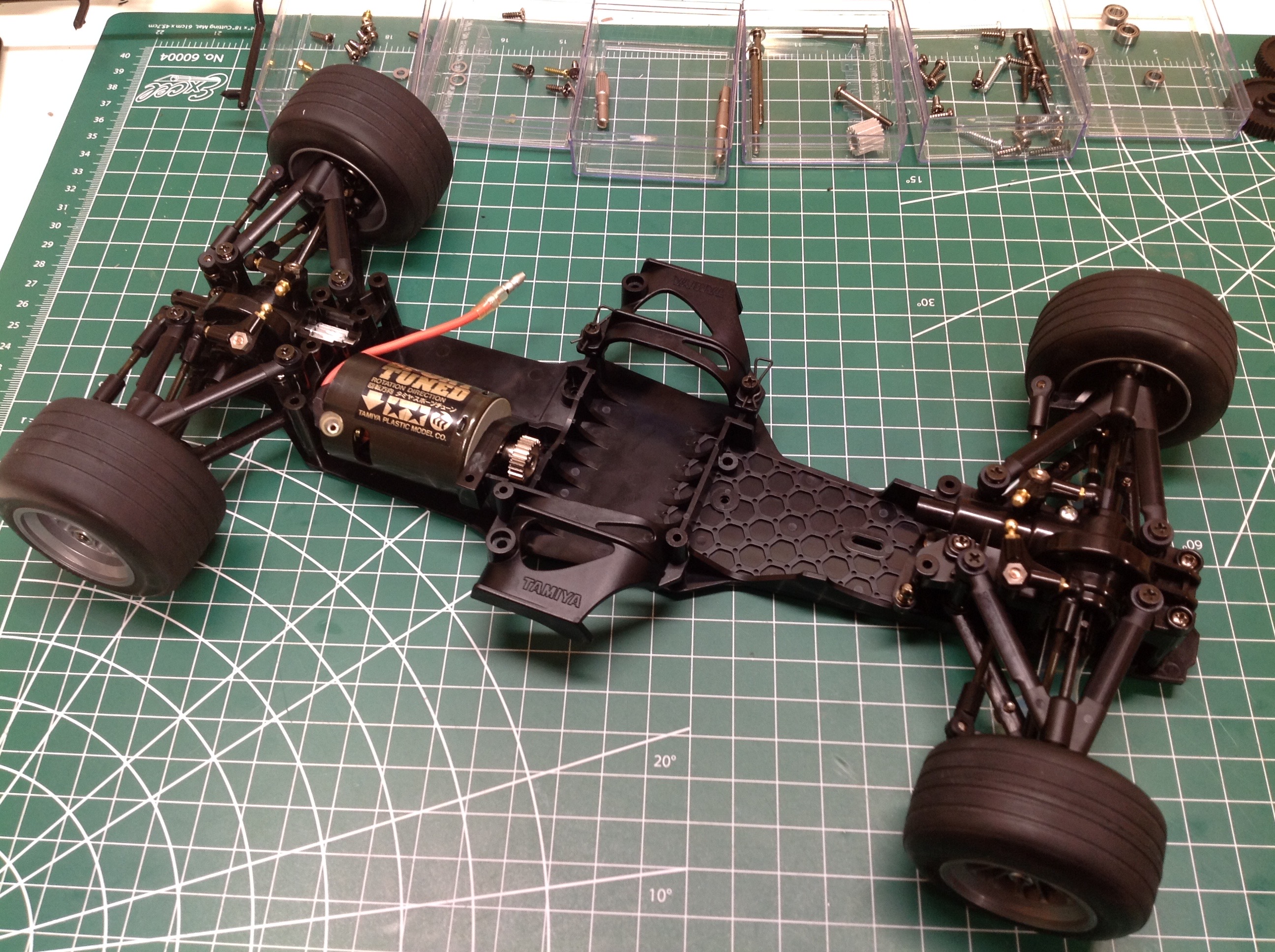
The Sport Tuned motor uses a 23 tooth pinion with a fixed mesh that cannot be adjusted. The motor installation is shown at right, but at this point there is still no connection between the motor and the rear axle.
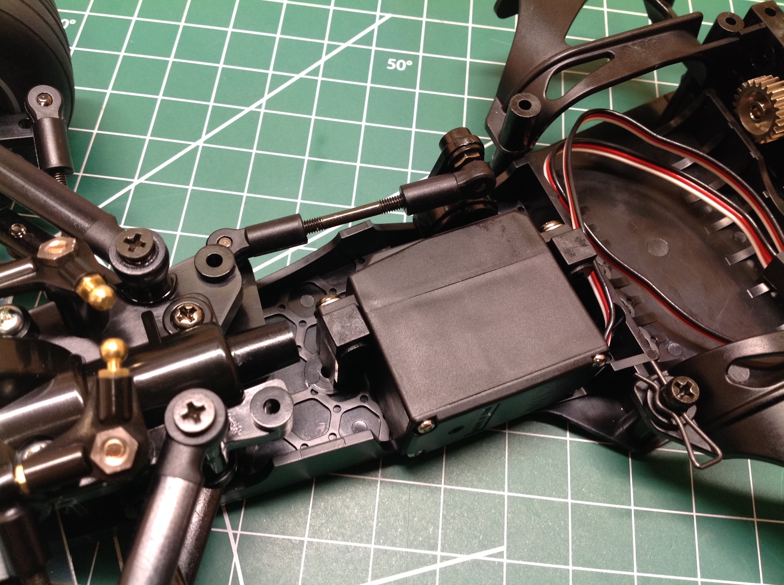
The servo is attached to the chassis with a couple of posts and drives the steering crank through a servo saver. After that an upper chassis tub can be installed which effectively hides the servo and also stiffens the chassis.
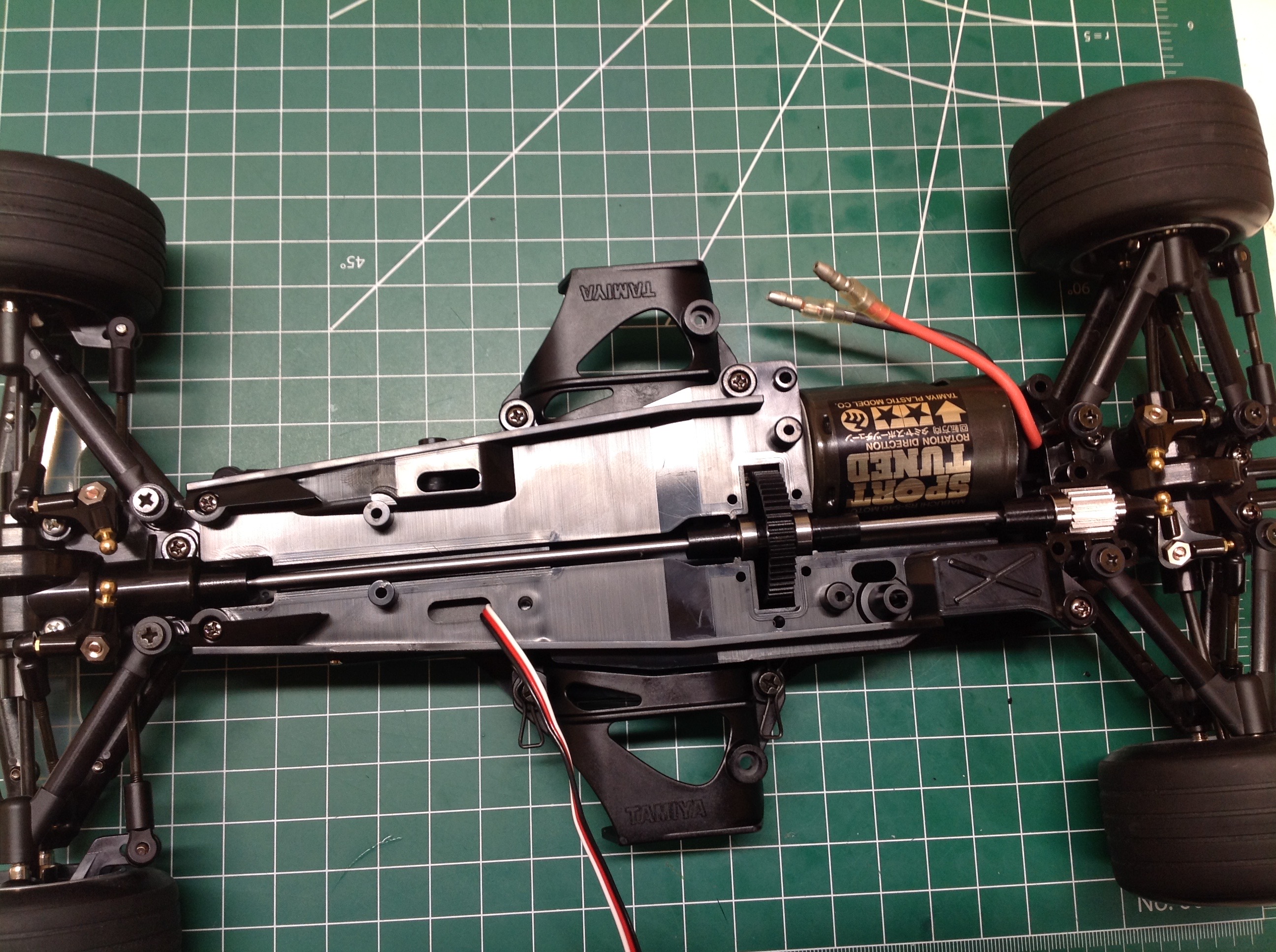
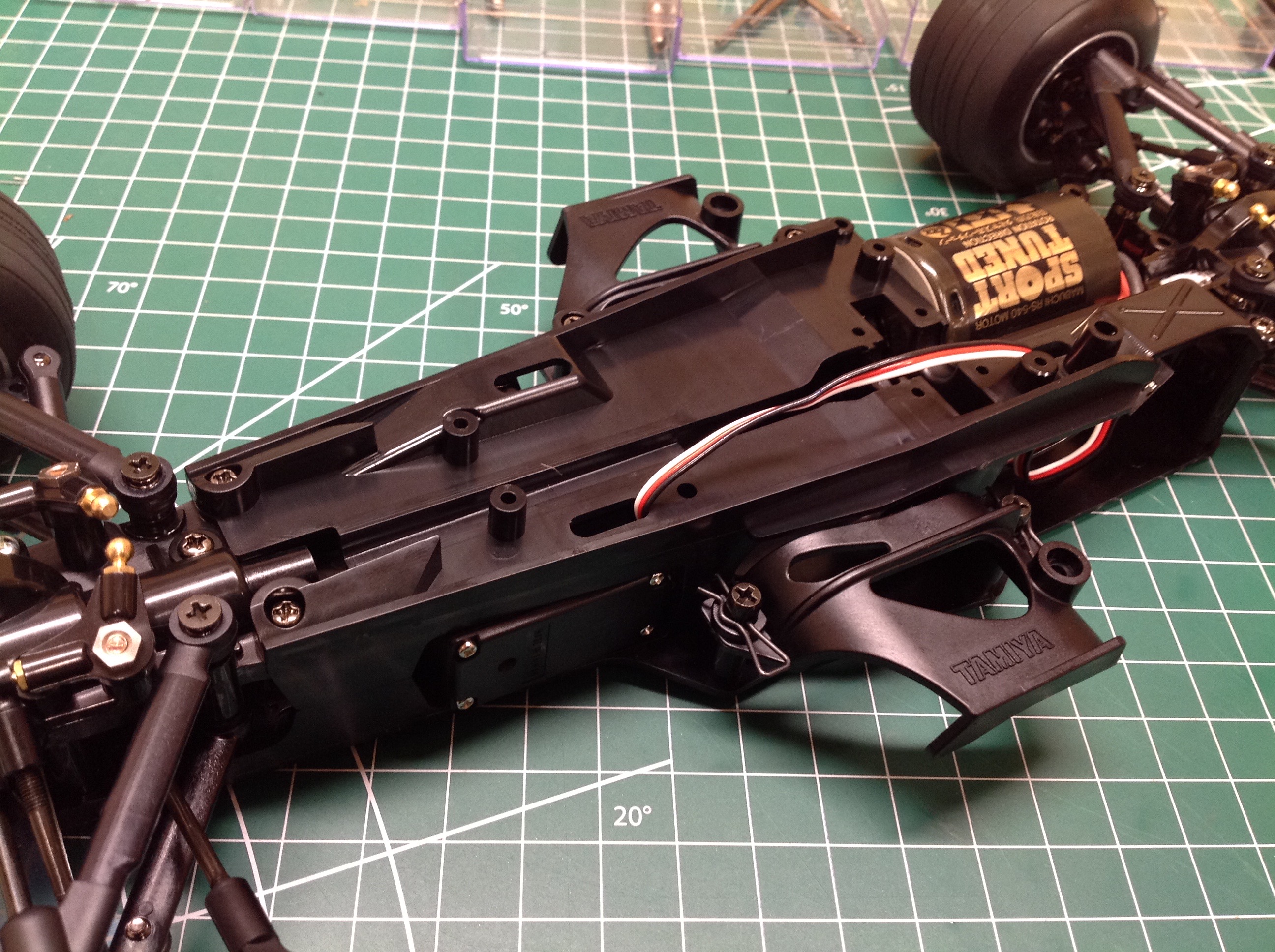
This center gear is neither a differential nor a slipper clutch. The spur grabs the motor pinion in the center of the vehicle and then a pair of prop shafts run fore and aft to connect to the differentials. These prop shafts are buried in the upper tub to prevent anything from fouling them.
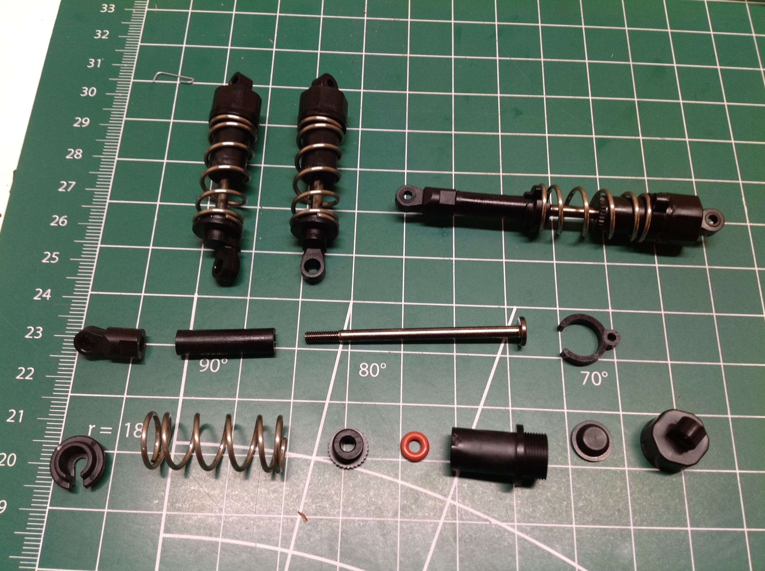
The shocks are oil dampers but have some differences compared to standard CVAs. The rod end of the rear dampers is very long, and the springs are extremely stiff since the stroke is so short. The shocks are installed on ball joints longitudinally in the chassis.
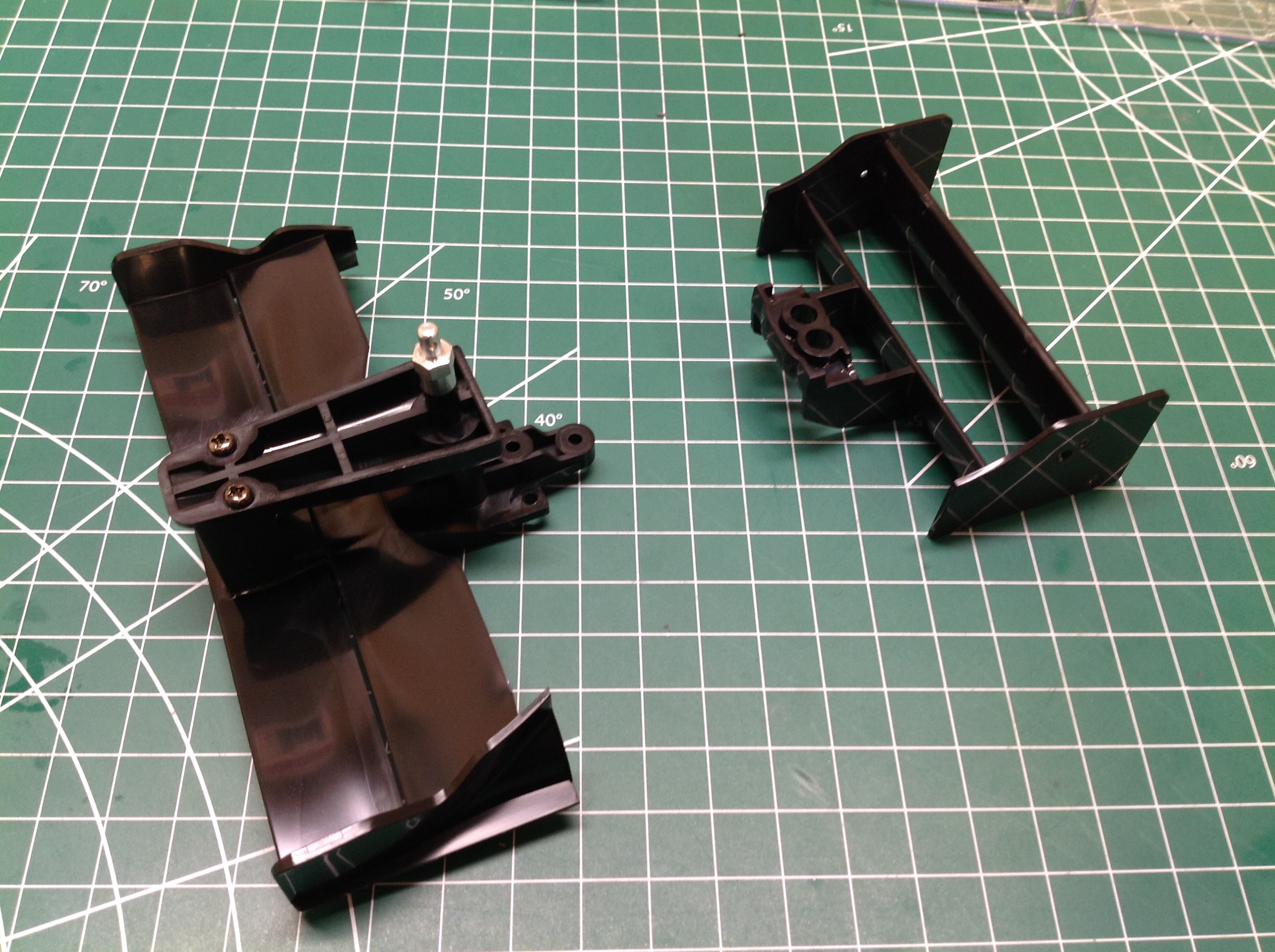
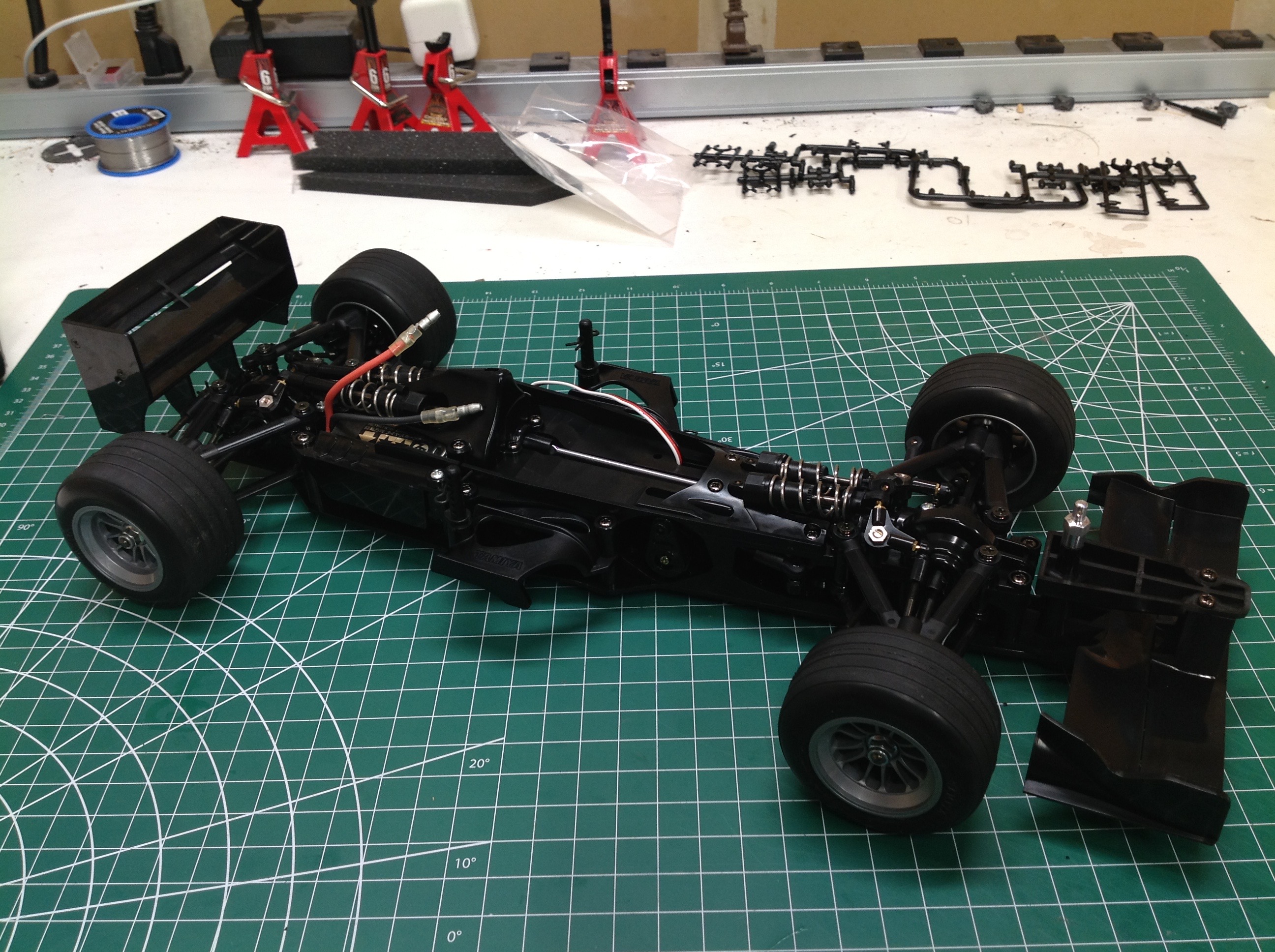
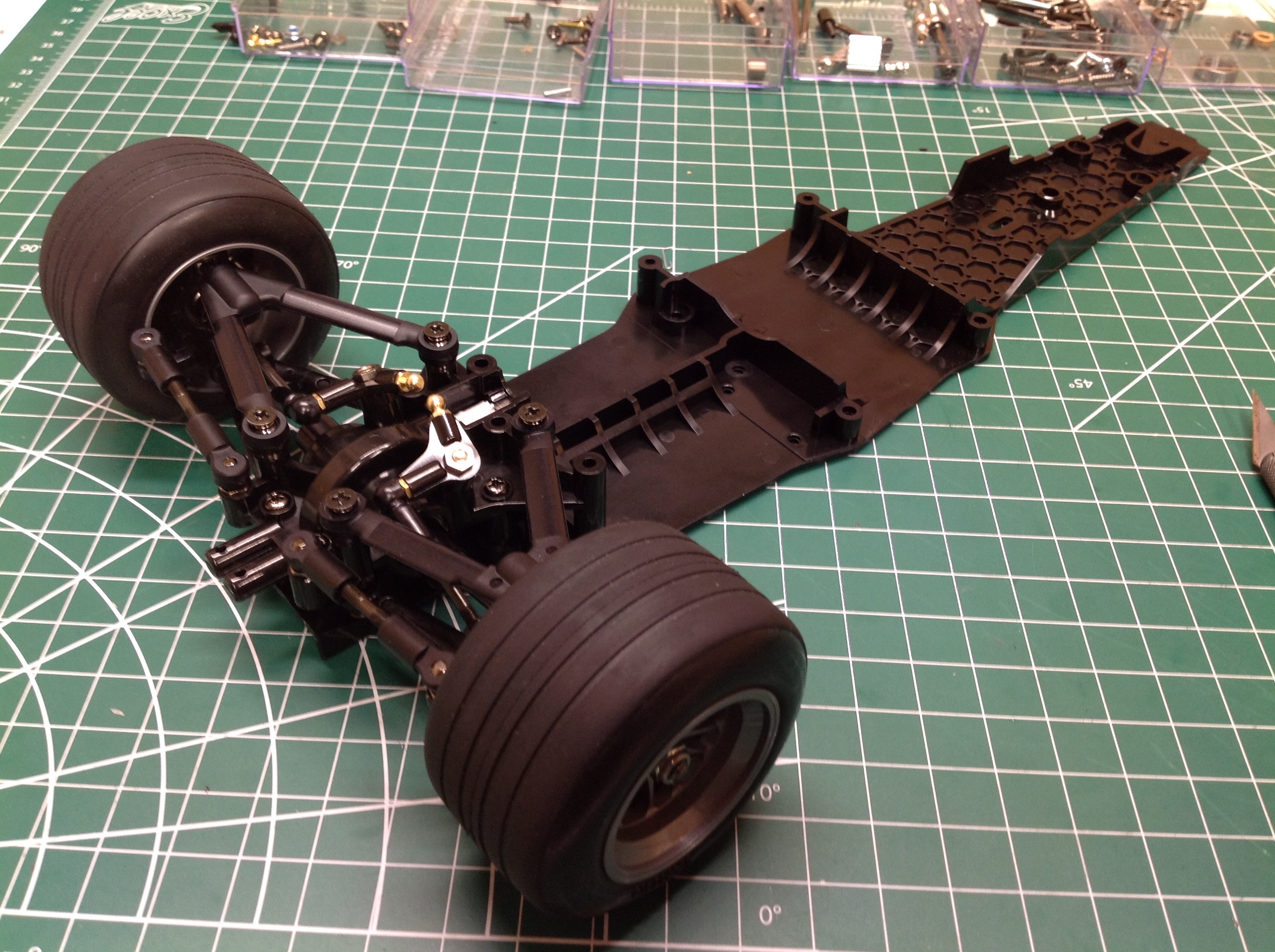
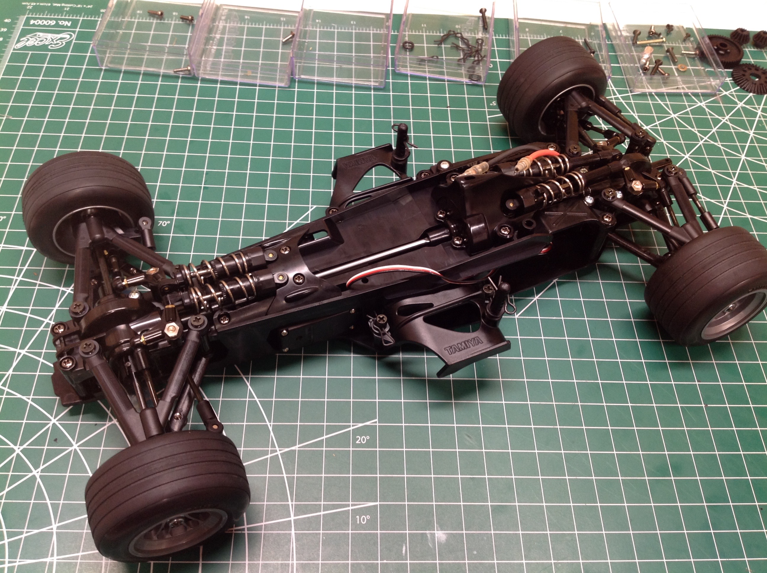
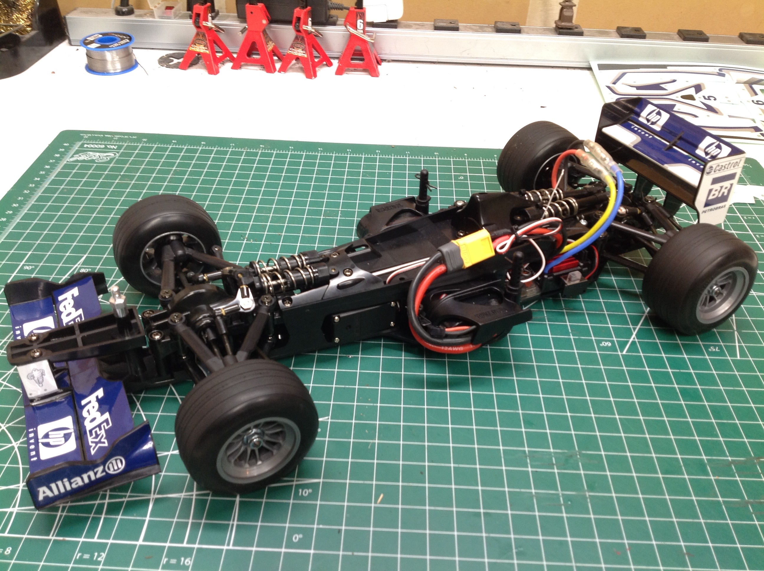
The last thing to do to complete the rolling chassis is install the front and rear wings, glue the tires, and install the wheels. The result is shown on the right. The electronics tuck into a pocket on the left side, opposite the motor.
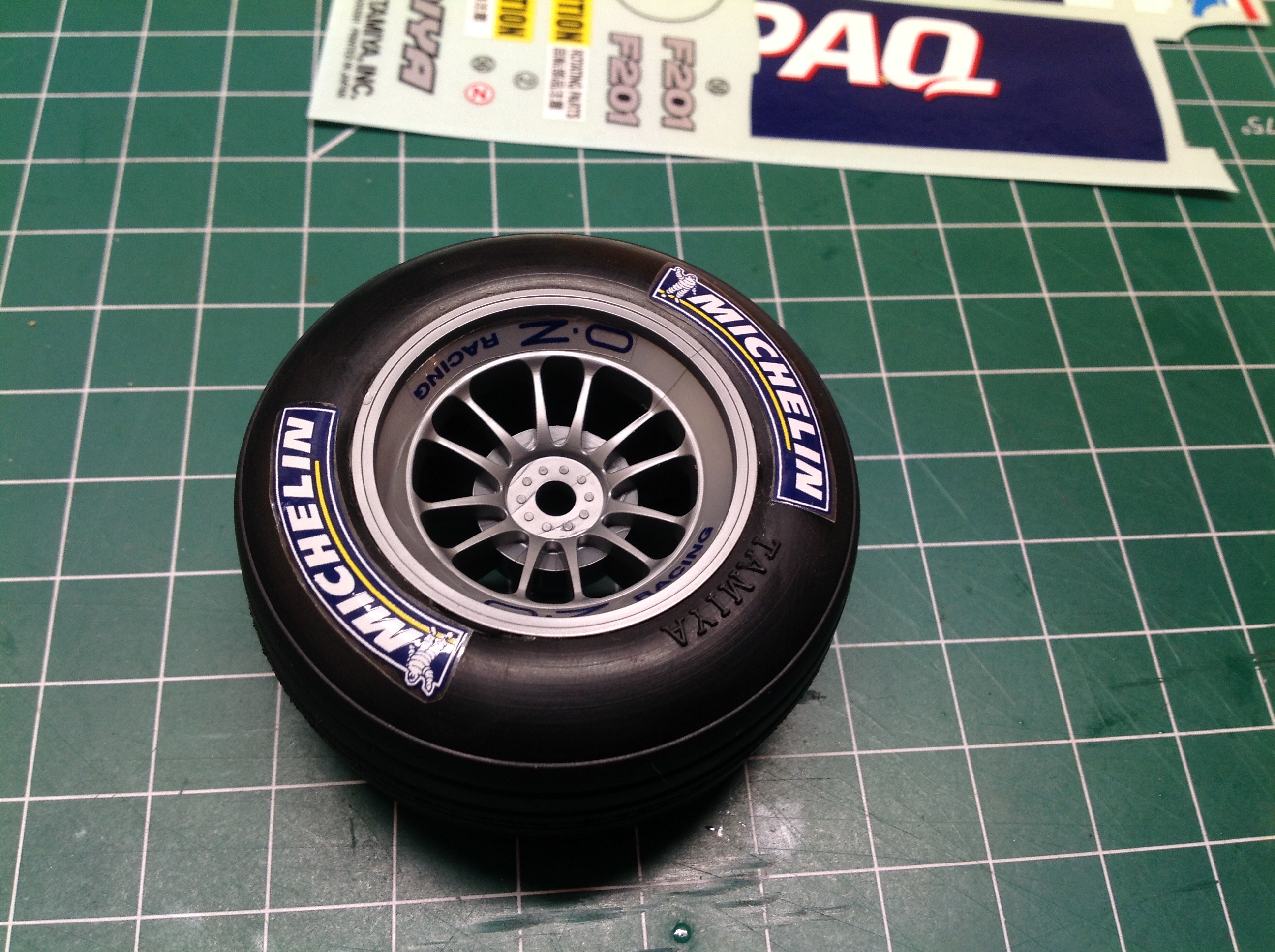
A significant number of stickers are applied to areas other than the body. The first such areas are the front and rear wings. The tires also need some work. They need to be scrubbed clean and wiped with alcohol to make sure that the glue will adhere to them and that the Michelin stickers (which look awesome) will stay on.
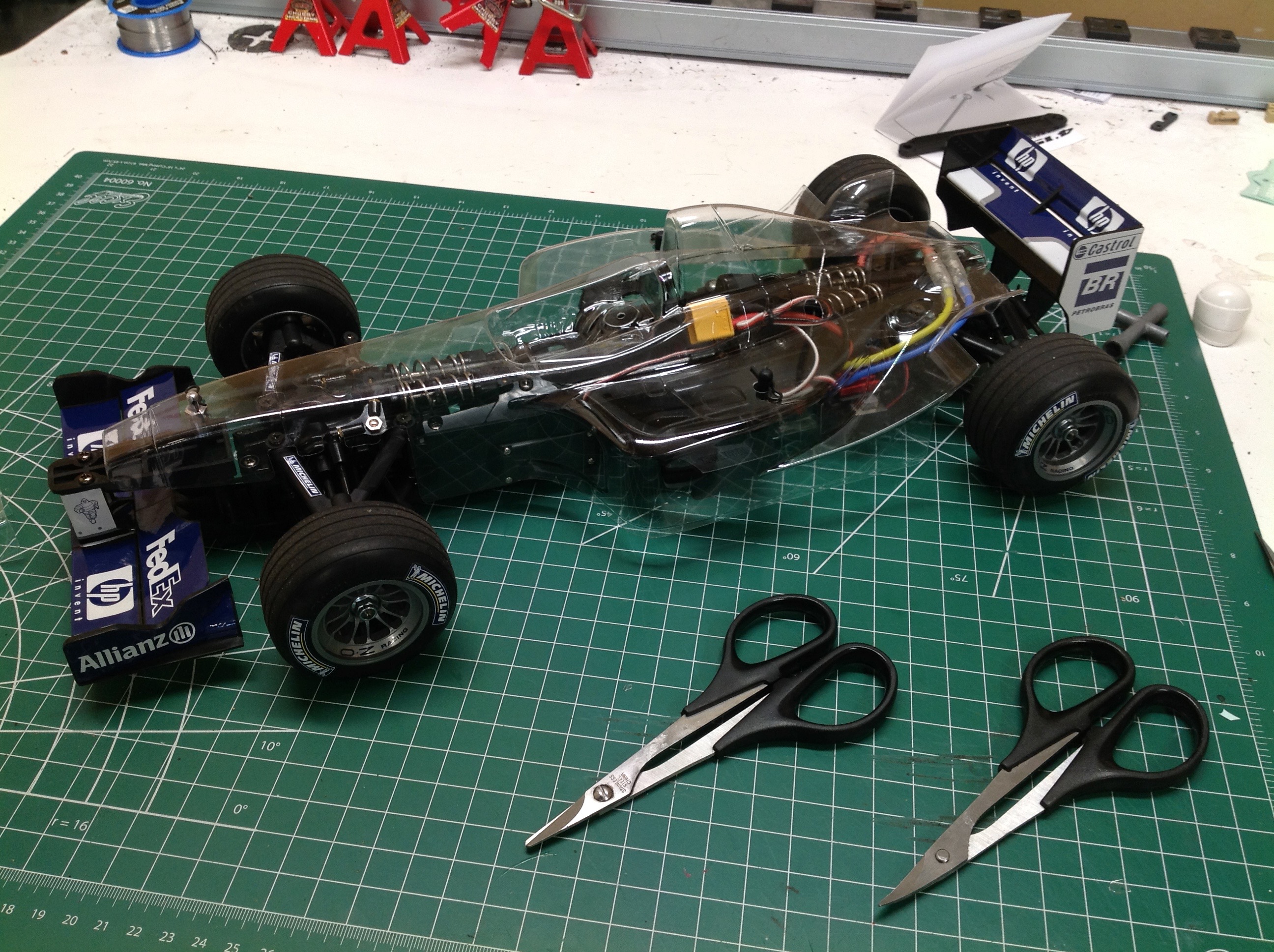
Now the body can be cut out. For some reason, this particular body comes without any overspray film which makes painting it a whole lot harder. There is a separate pointed part for the nose which gets stuck on with double sided tape.
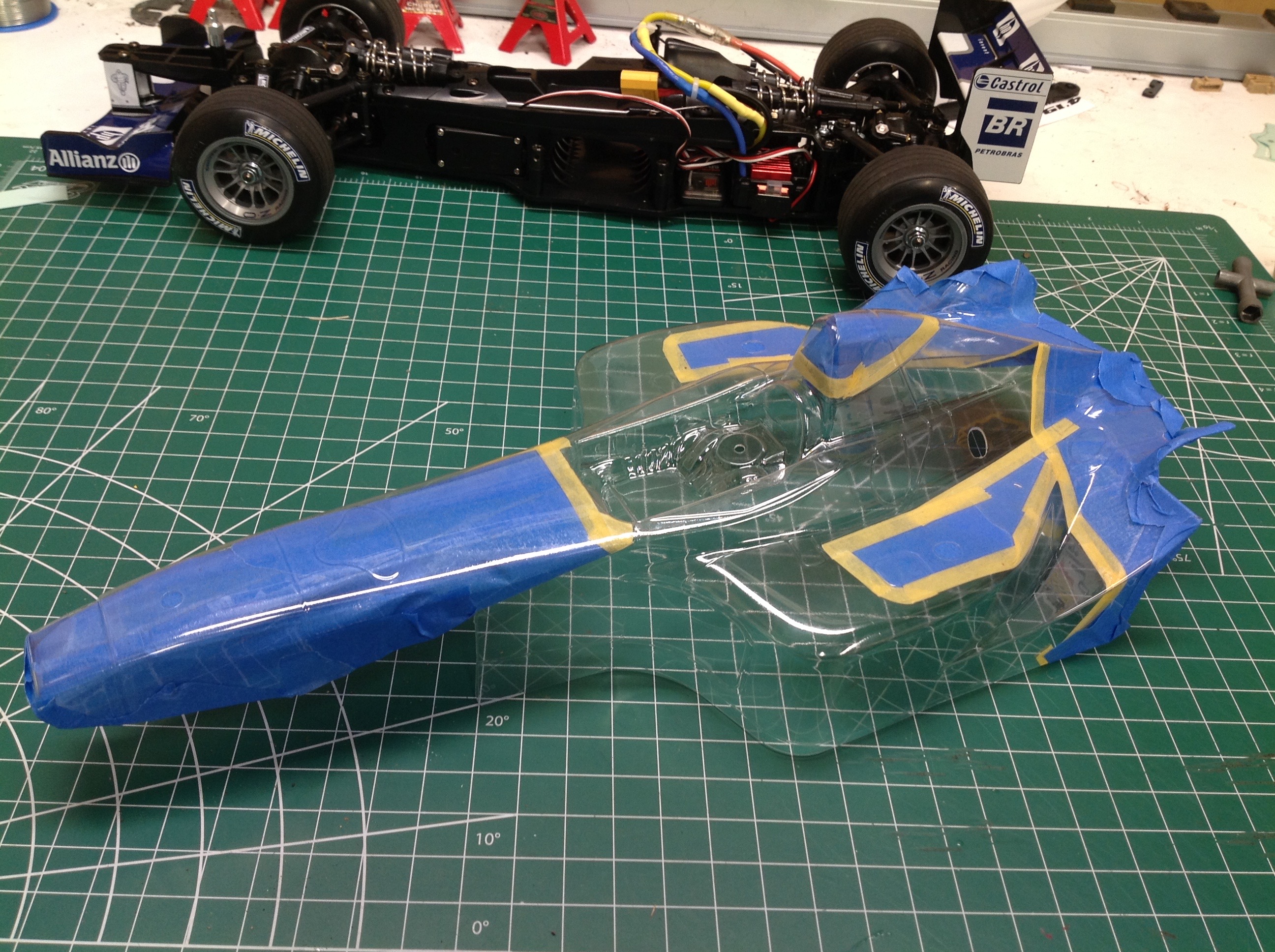
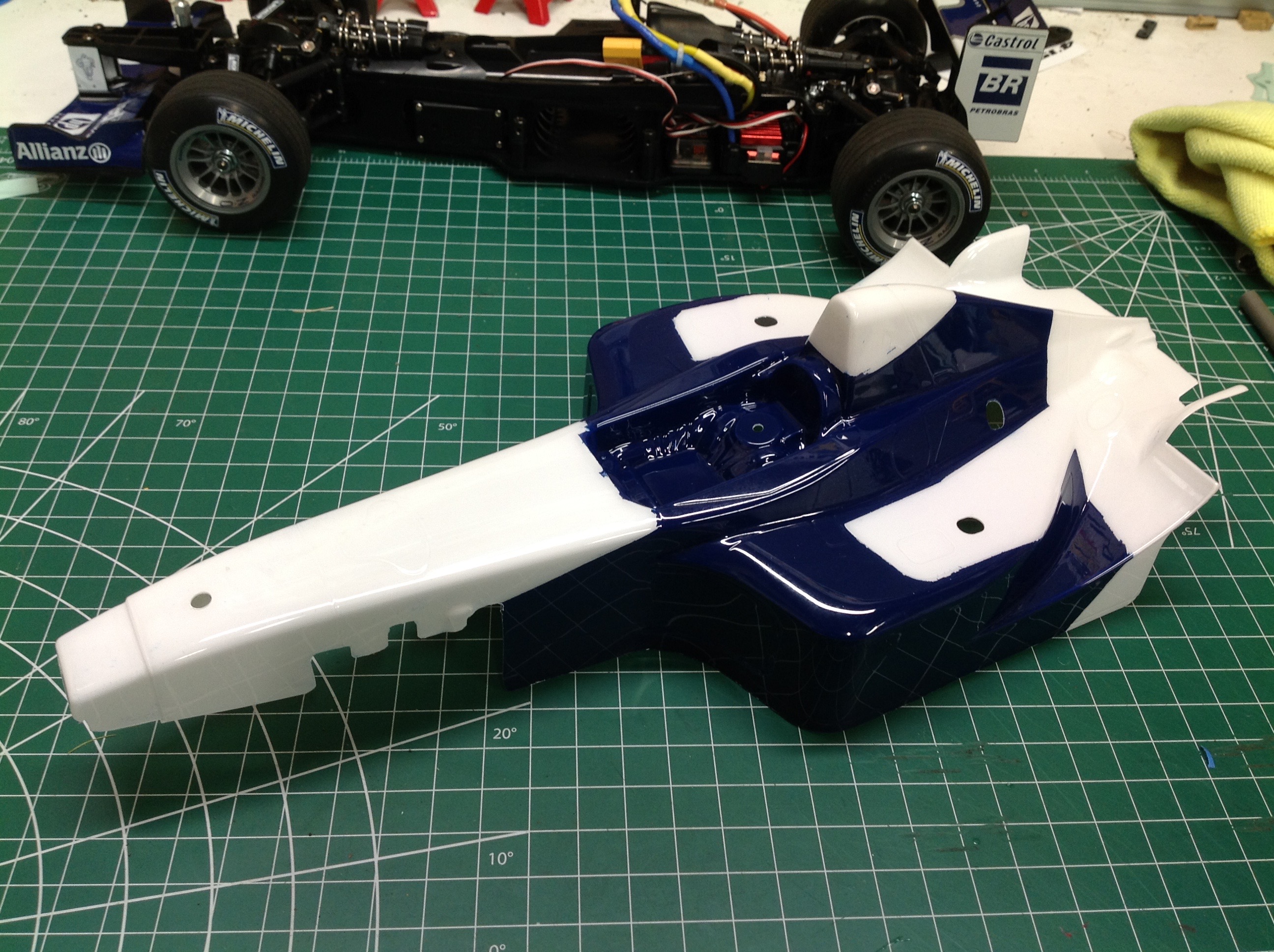
This complex masking took a significant amount of time to get right. It is really important that the line between blue and white be in the right place or the stickers will not match when they are applied. Based on the results on the right, I must have done a fairly decent job of it. This blue looks much too dark to be a good match for the real Williams in my eyes, but it is correct for the model because it matches the stickers perfectly.
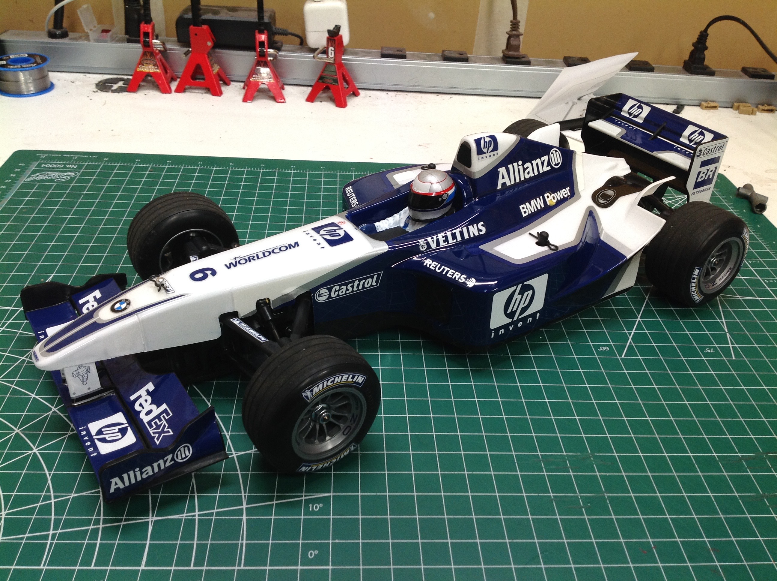
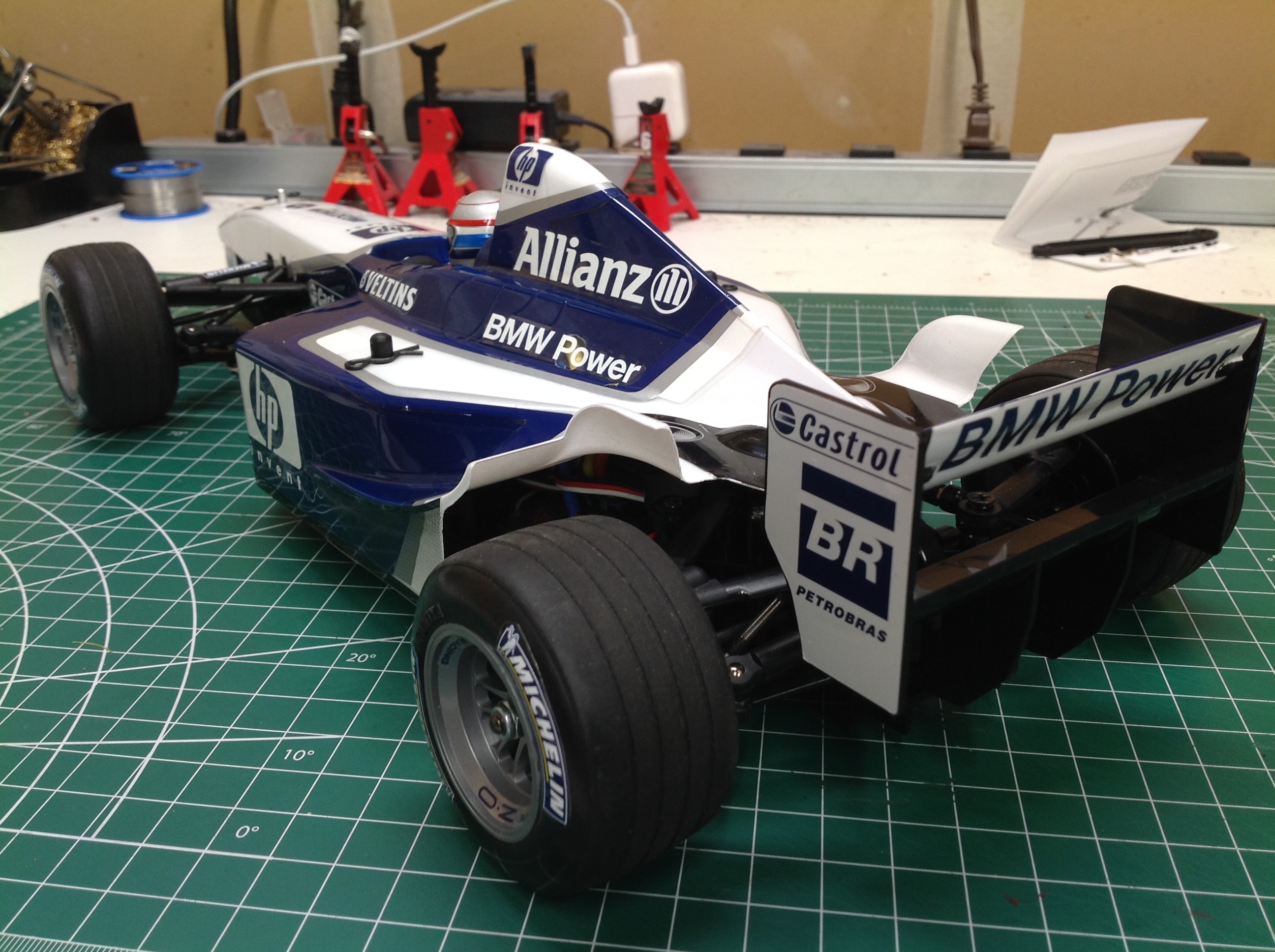
Once the body is painted the long, painstaking sticker application process can begin. The results are well worth the effort since this car looks magnificent. Additional painting is required on the outside of the body for the driver figure and the helmet. The kit includes decorations for both the #5 (Ralf Schumacher) and #6 (Juan Pablo Montoya) car in both the HP and Compaq liveries. I chose the #6 HP car because I like the helmet better.
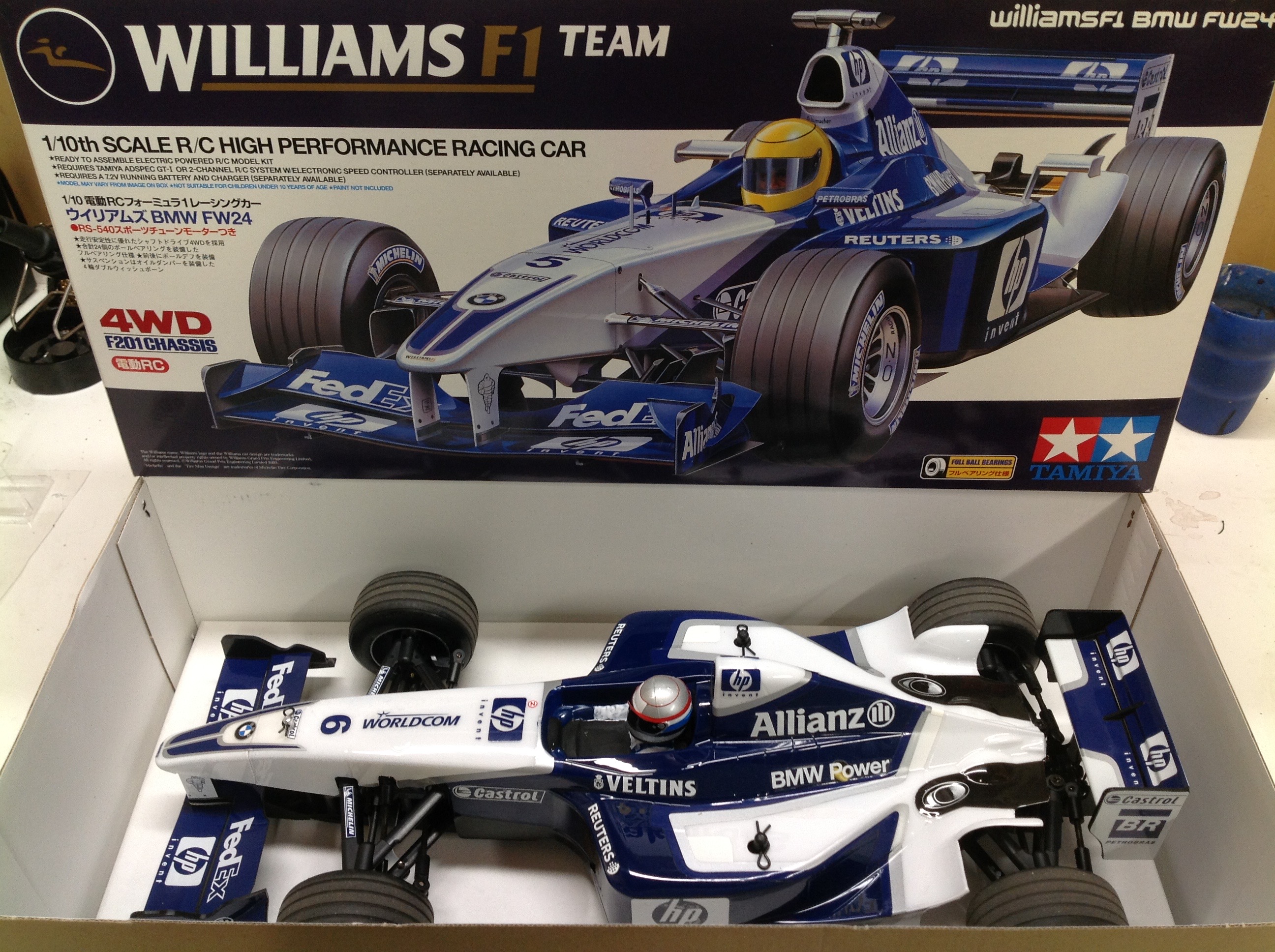
I am a little disappointed that the box art is so different from the model. The art on the box is clearly based on the rear car and includes a wide assortment of aerodynamic attachments that are not present on the model. The blue is much lighter on the box as well.