Tamiya Ferrari F40 Project
Page 1: Assembly
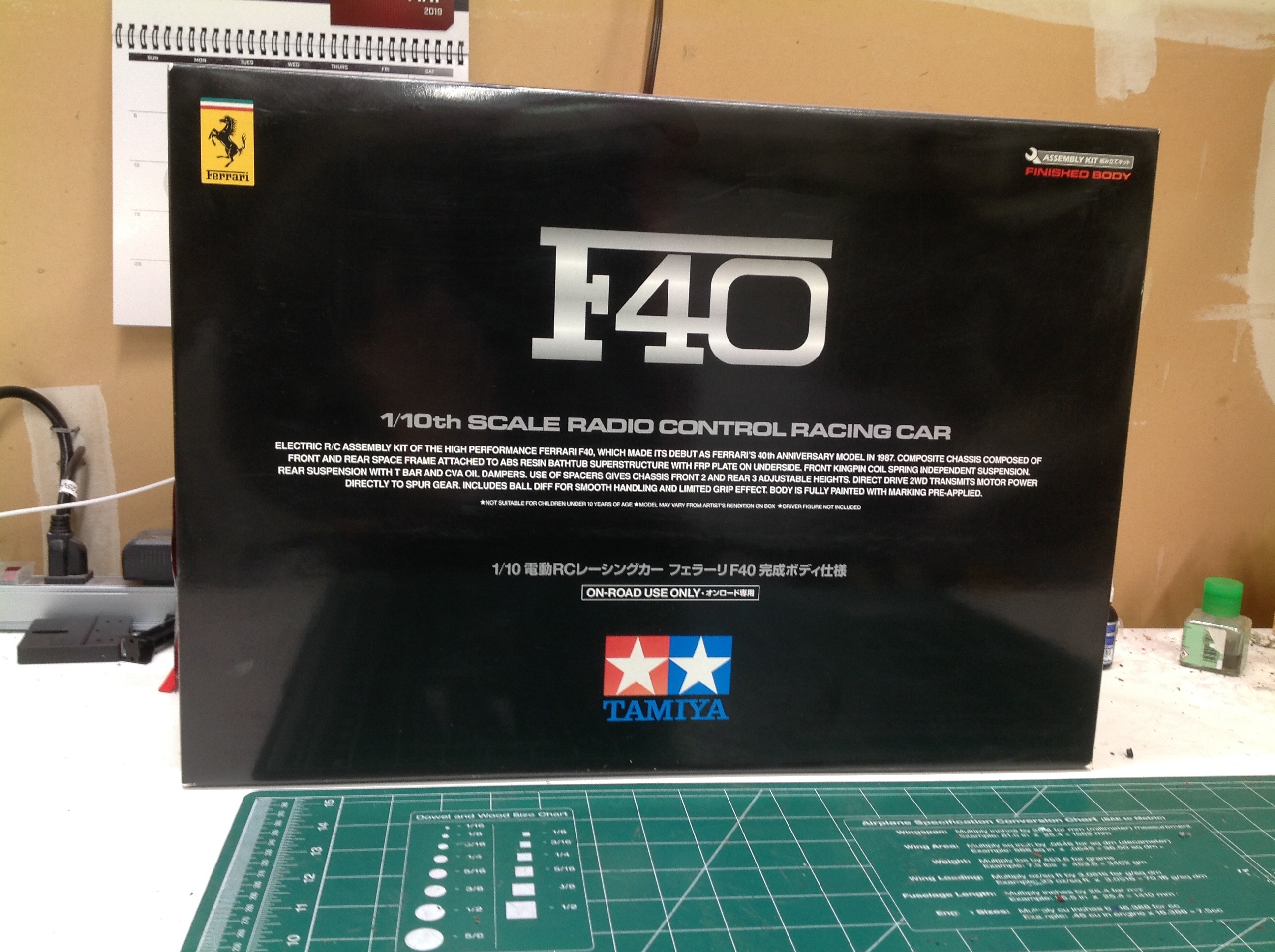
For such a pretty model, this kit comes in a very bland box. There
is no artwork at all on the box, just a plain black background with
some text. I don't know if this was a marketing restriction
related to the license with Ferrari or if there was something else
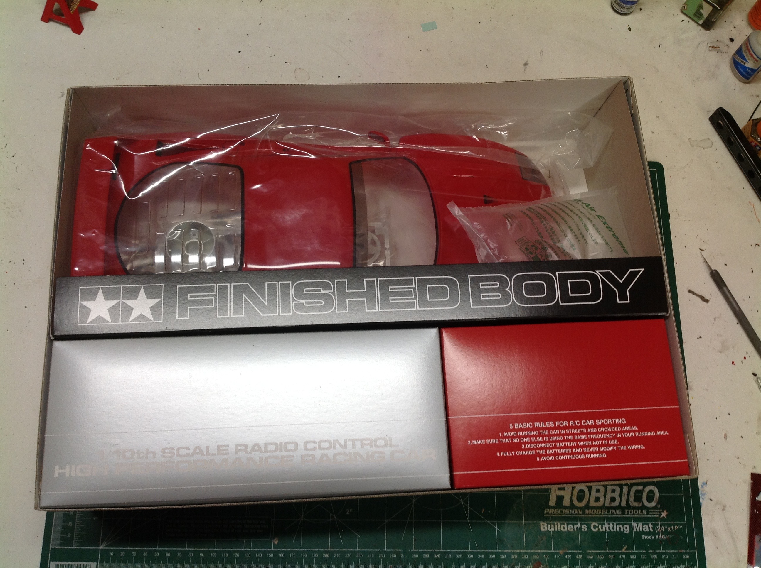
behind it. There are no blister packs inside but there are boxes
for the hardware and plastic parts and the finished body gets its own
slot. The body is finished just as perfectly as you would expect
from Tamiya.
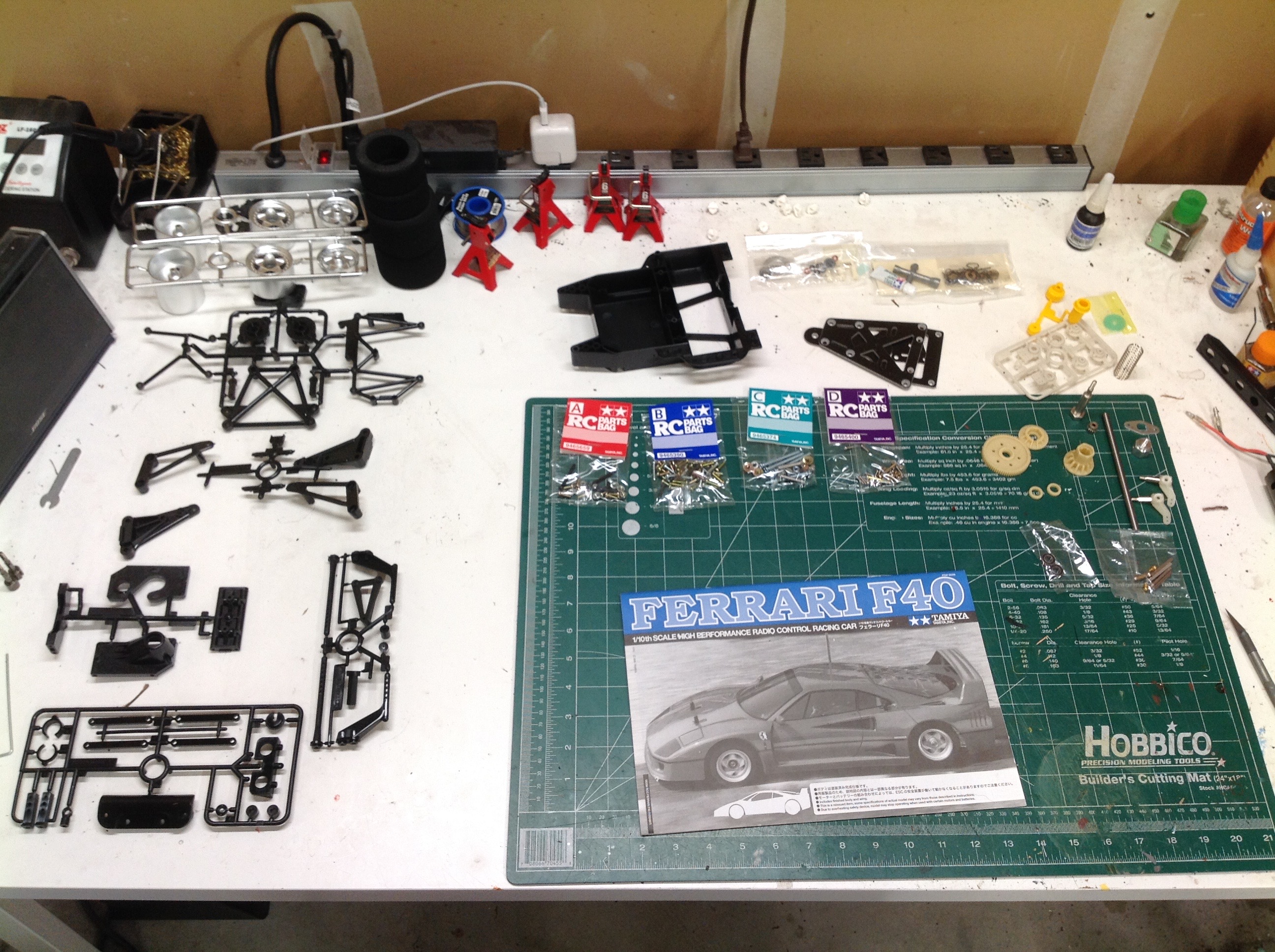
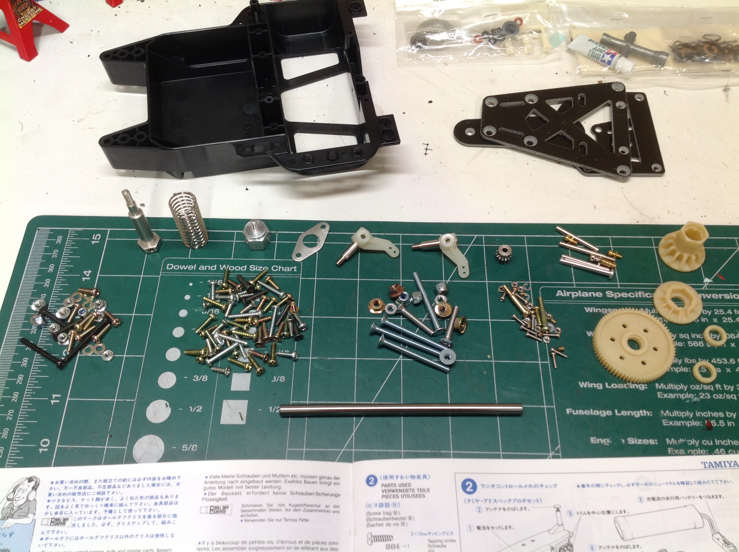
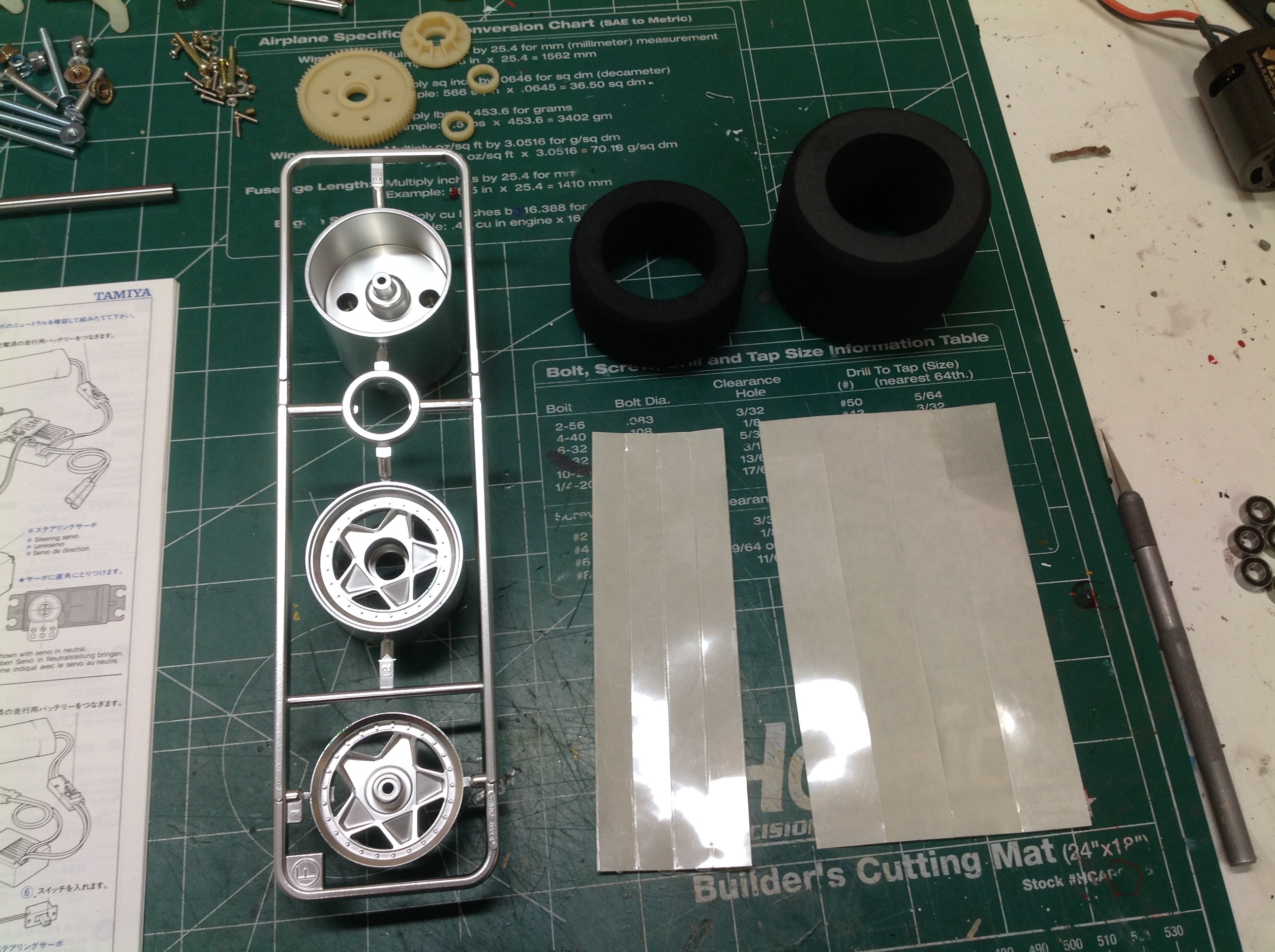
Upon laying out the parts on the table, you can see that this is a very
simple chassis. There are few parts. There is quite a bit of
hardware though as you can see in the image on the right. In
particular the hardware related the rear axle includes part types I
haven't seen before.
This is the first model I have ever assembled using foam tires and I
didn't know what I was doing. The instructions are quite clear,
but only to a point. The tires are affixed to the smooth
cylindrical wheels using double sided tape. The idea is to have
only a small amount of adhesive exposed when you push on the tire, then
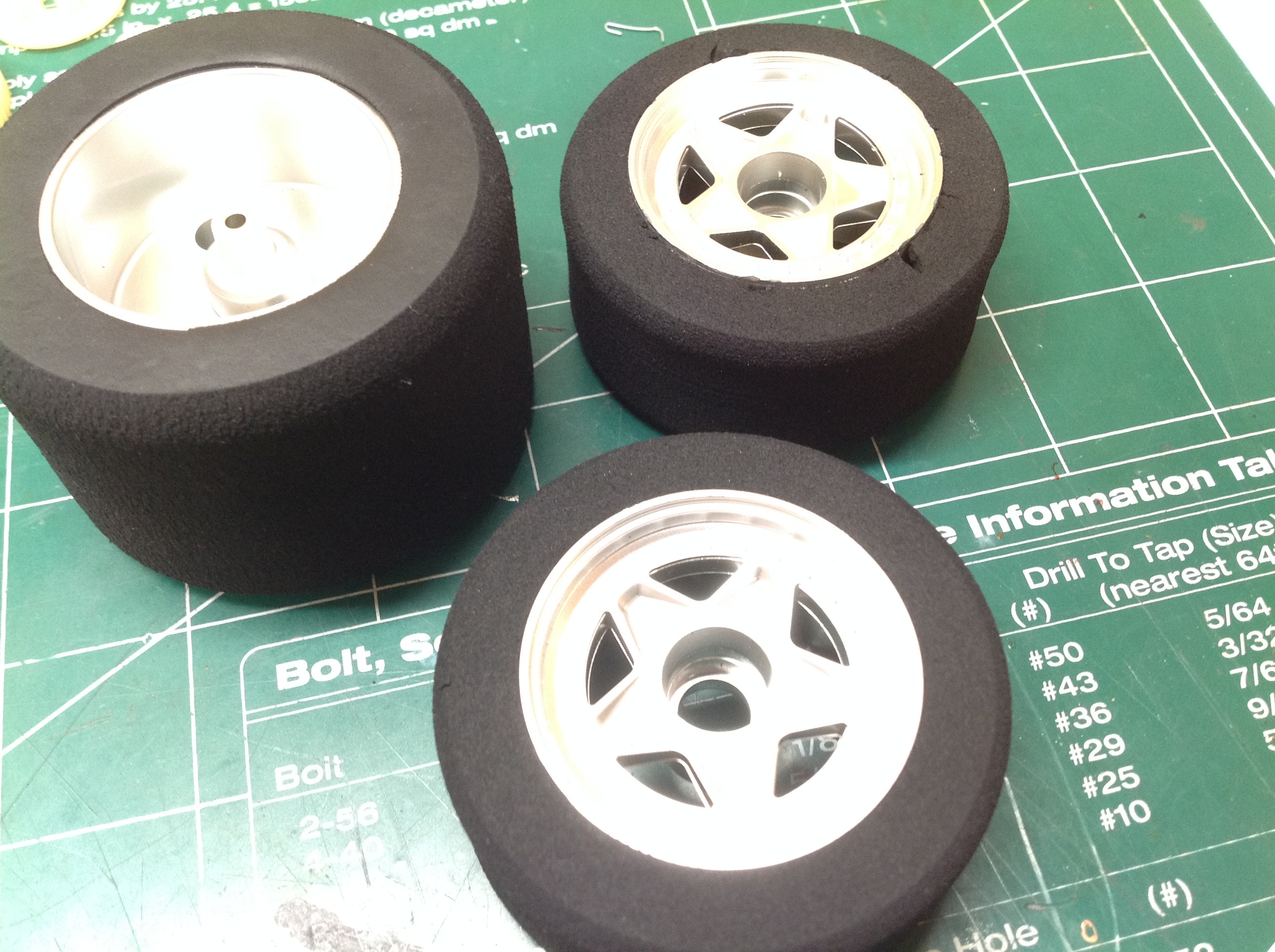
pull the backing off the tape once the tire in in place. This
worked fine for the rear tires, but for the front tires I found that the
tire squished as it was pushed on and was therefore not as wide as the
wheel. I tried to fix this by pulling on the tire but this only
caused chunks to break off the tire and cracks to form. You can
see some of the damage in the photo. It turns out it is OK for the
wheel to protrude beyond the tire. The tire should be pushed on
from the outside so it is flush on the visible edge, but the inner edge
doesn't matter. I paid the price for this mistake on my first run.
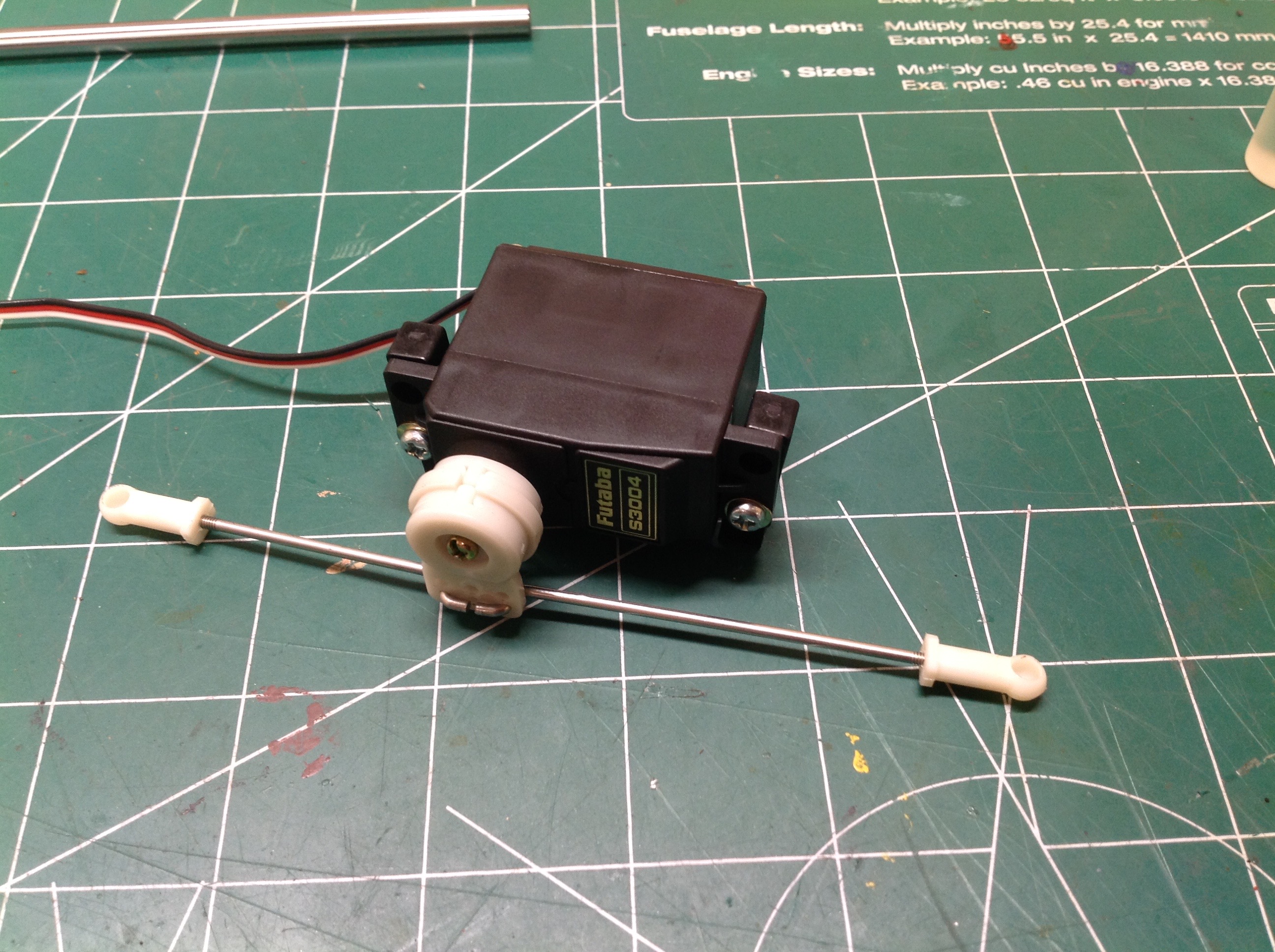
The steering on this car is about as simple as it gets. The
plastic servo saver attaches to the servo output spline, and the
steering tie rods link directly to that. No bellcranks. In
fact, the inner edge of the links don't even have rod ends. There
are Z-bends in the wire.
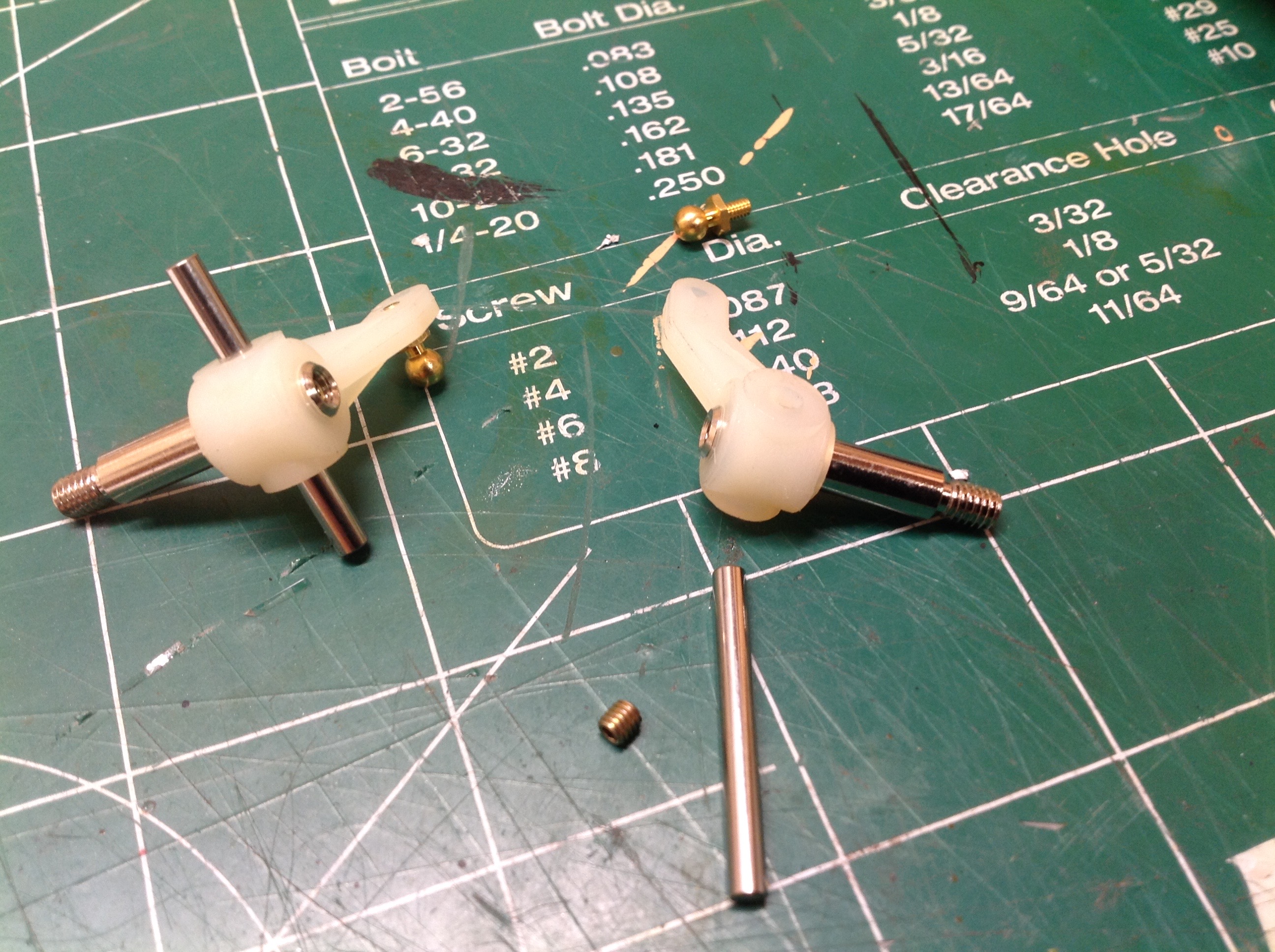
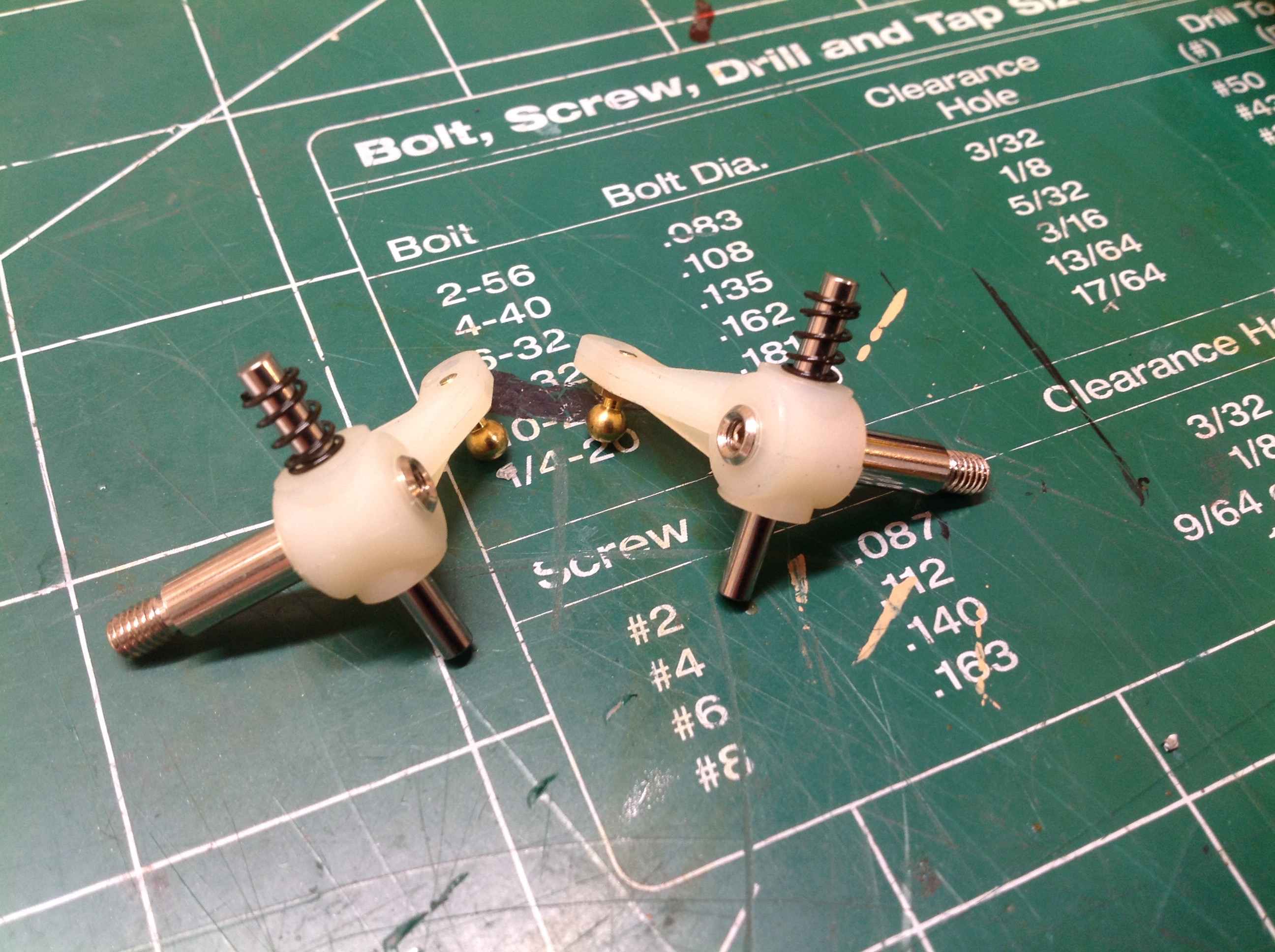
The front "suspension" can barely be called such. Each steering
knuckle has a single vertical steel rod used as a kingpin which is
retained with a set screw. A tiny spring sits on the upper side of
the kingpin.
The opening in the C-hub is bigger than the steering knuckle which
allows it to float up and down. This motion, and any flexibility
in the control arms, accounts for all the movement of the front
suspension. The arms are connected to a small front bumper and an
FRP lower plate.
The steering servo attaches to the base plate with a couple of little
plastic mounting blocks. As you can see on the left, the mounting
holes are slotted which allows you to adjust the servo side to
side. This helps you get a good mechanical center, useful in the
days before electronic sub trim.
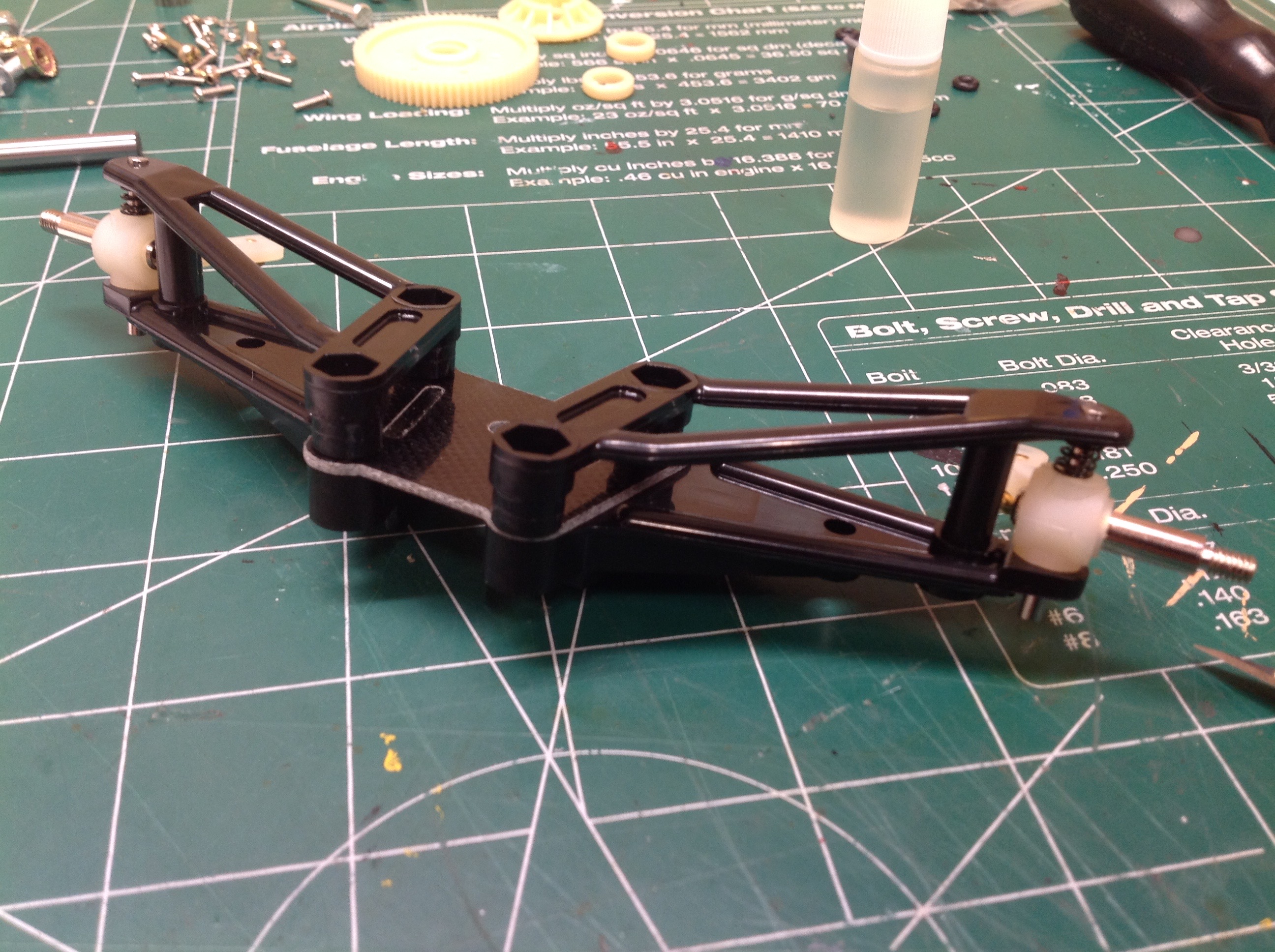
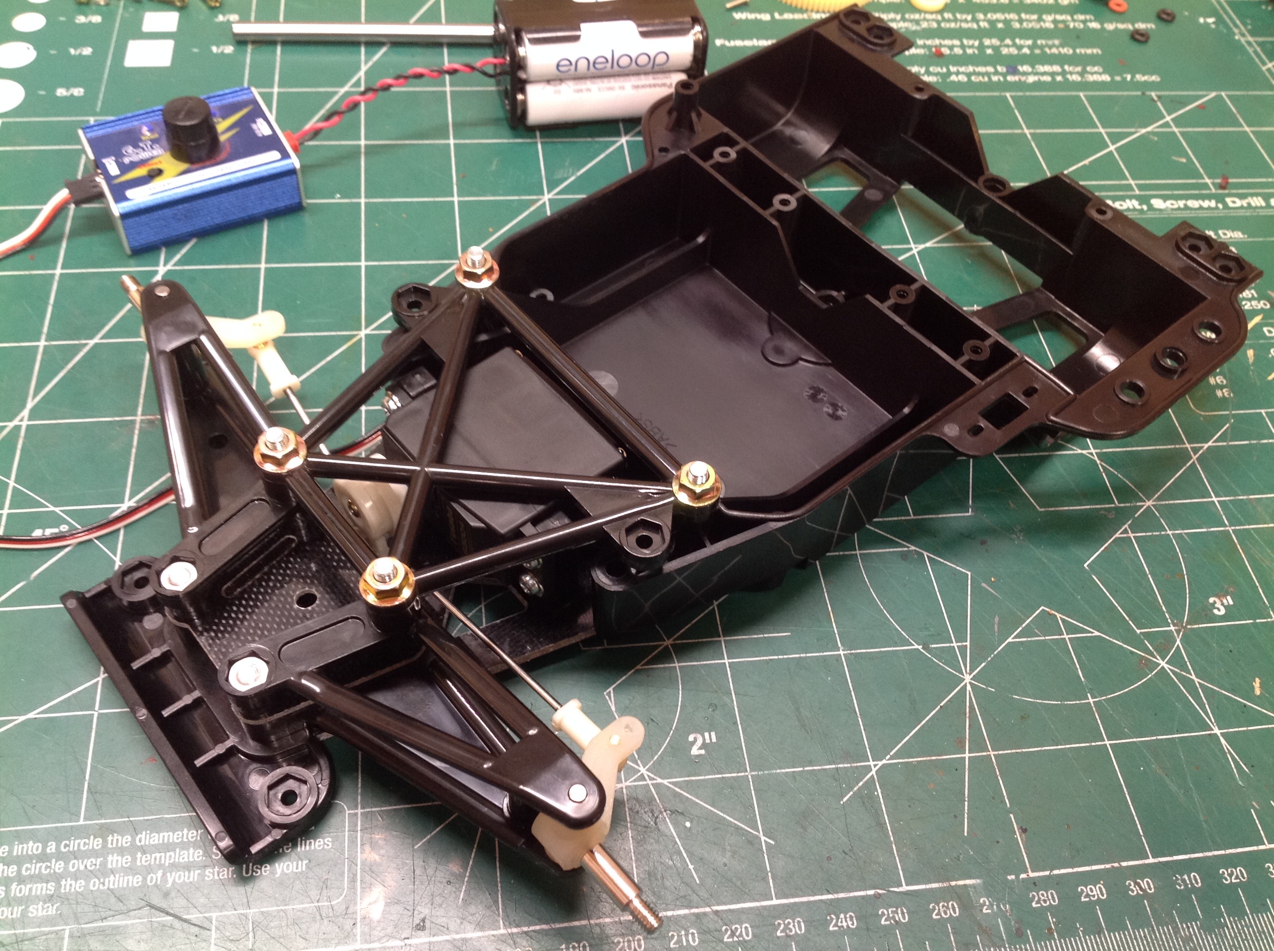
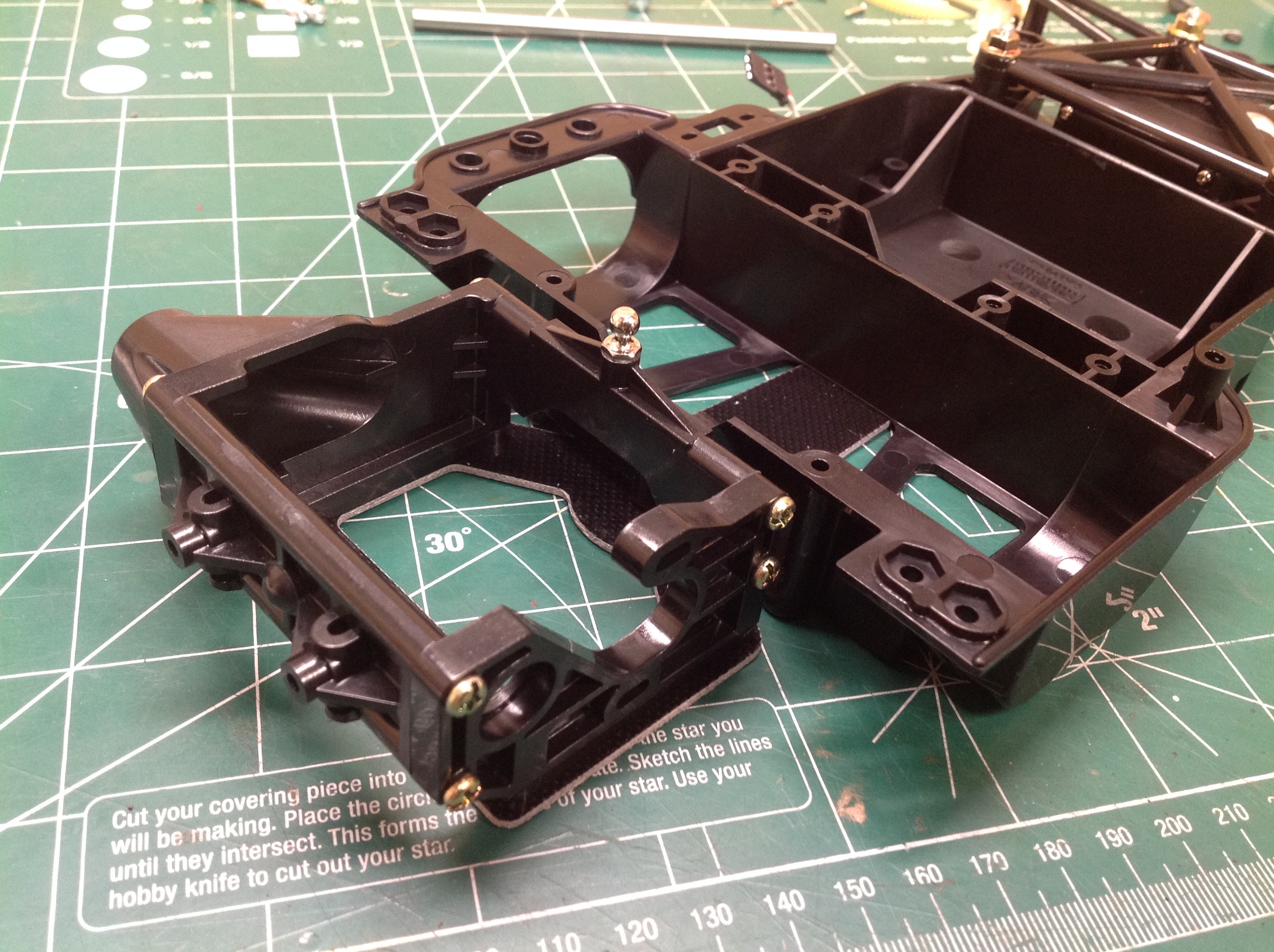
Now we can attach the front suspension to the main chassis
bathtub. You can see the large open space available for
electronics and the lateral slot for an old style rounded battery.
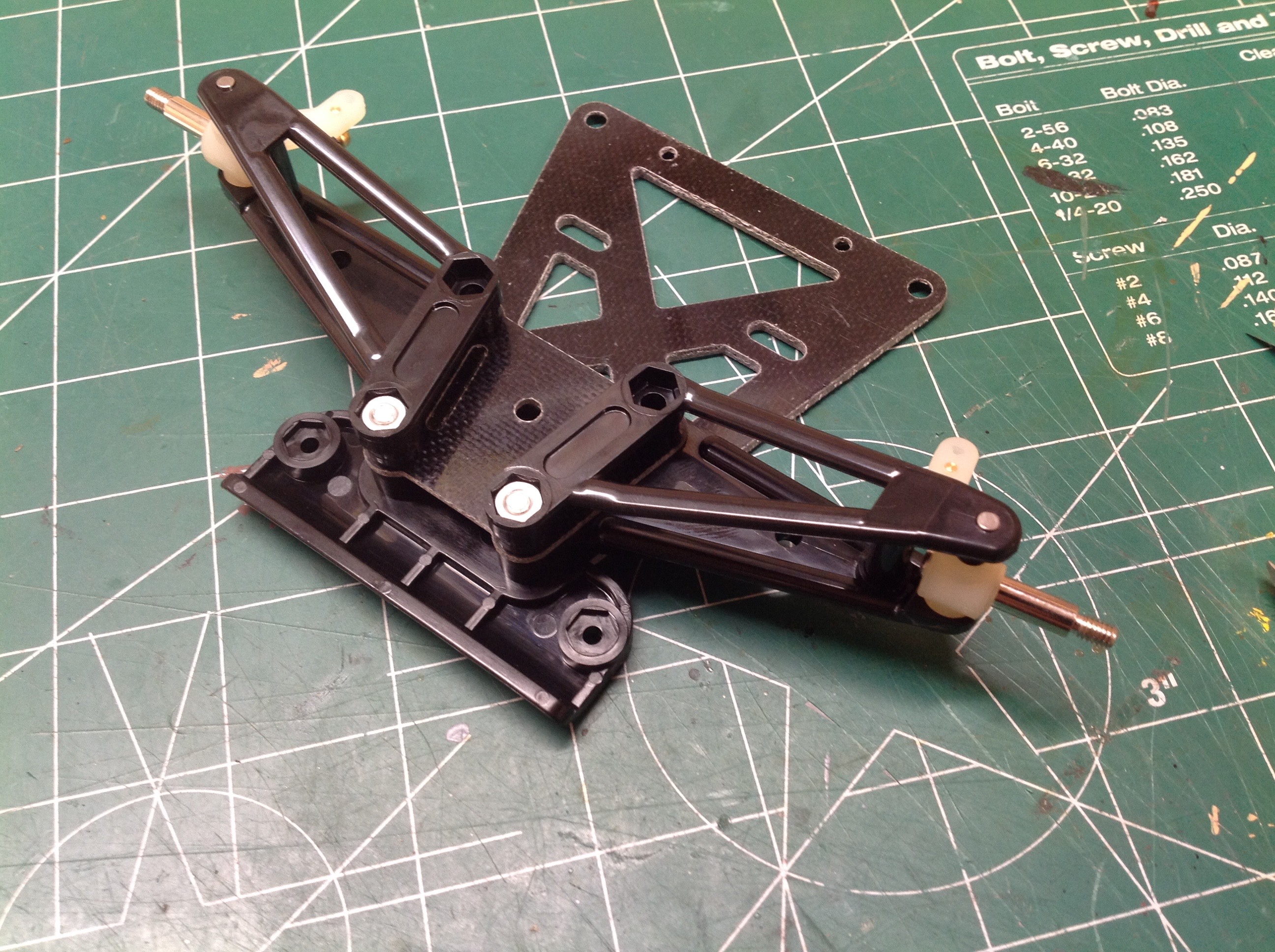
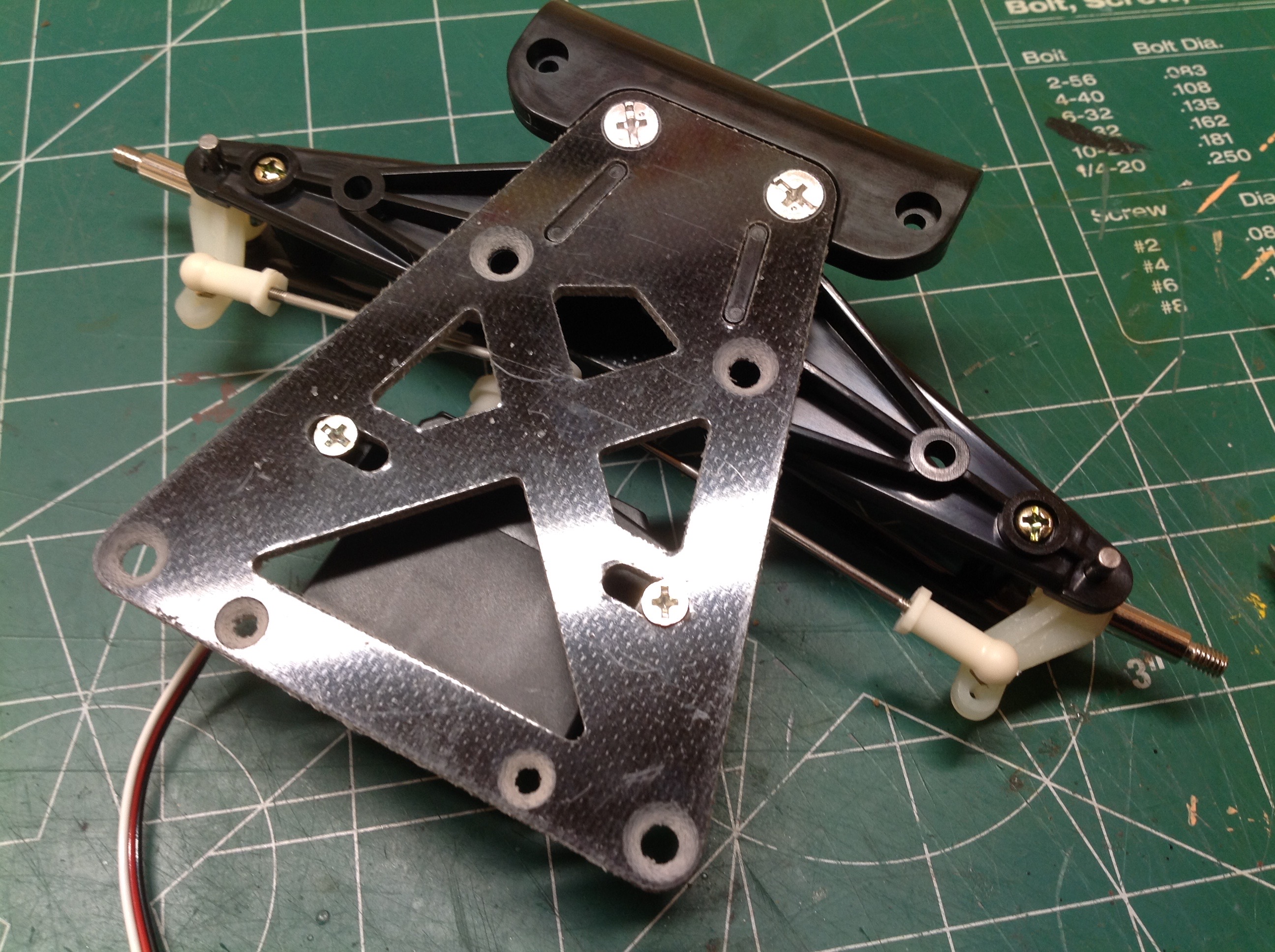
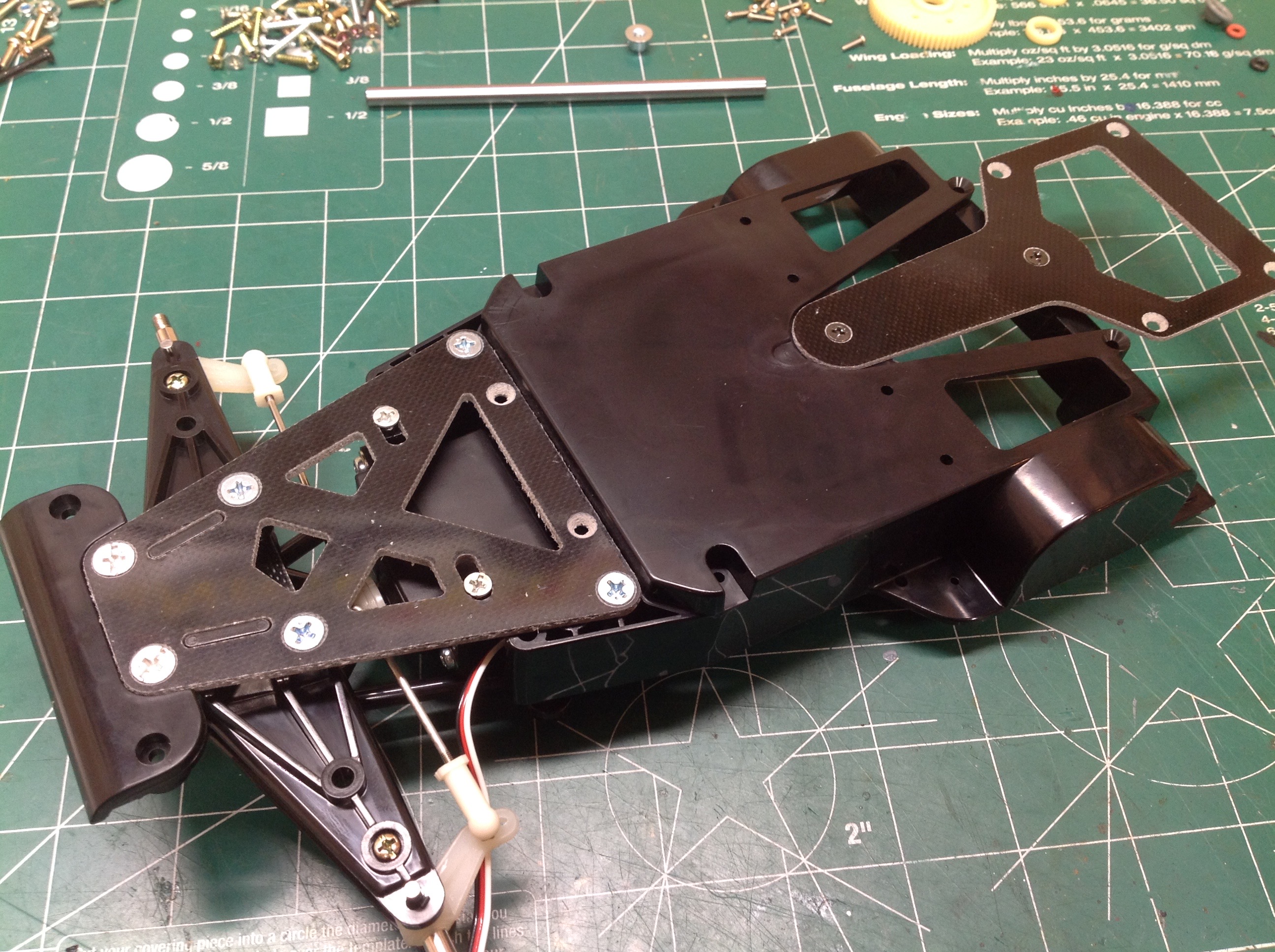
From beneath you can see the FRP rear chassis plate. It is
connected by only two screws in a longitudinal line, mounted with rubber
o-rings. This allows the whole plate to rock side to side.
This movement along with flexibility of the plate is the rear
suspension.
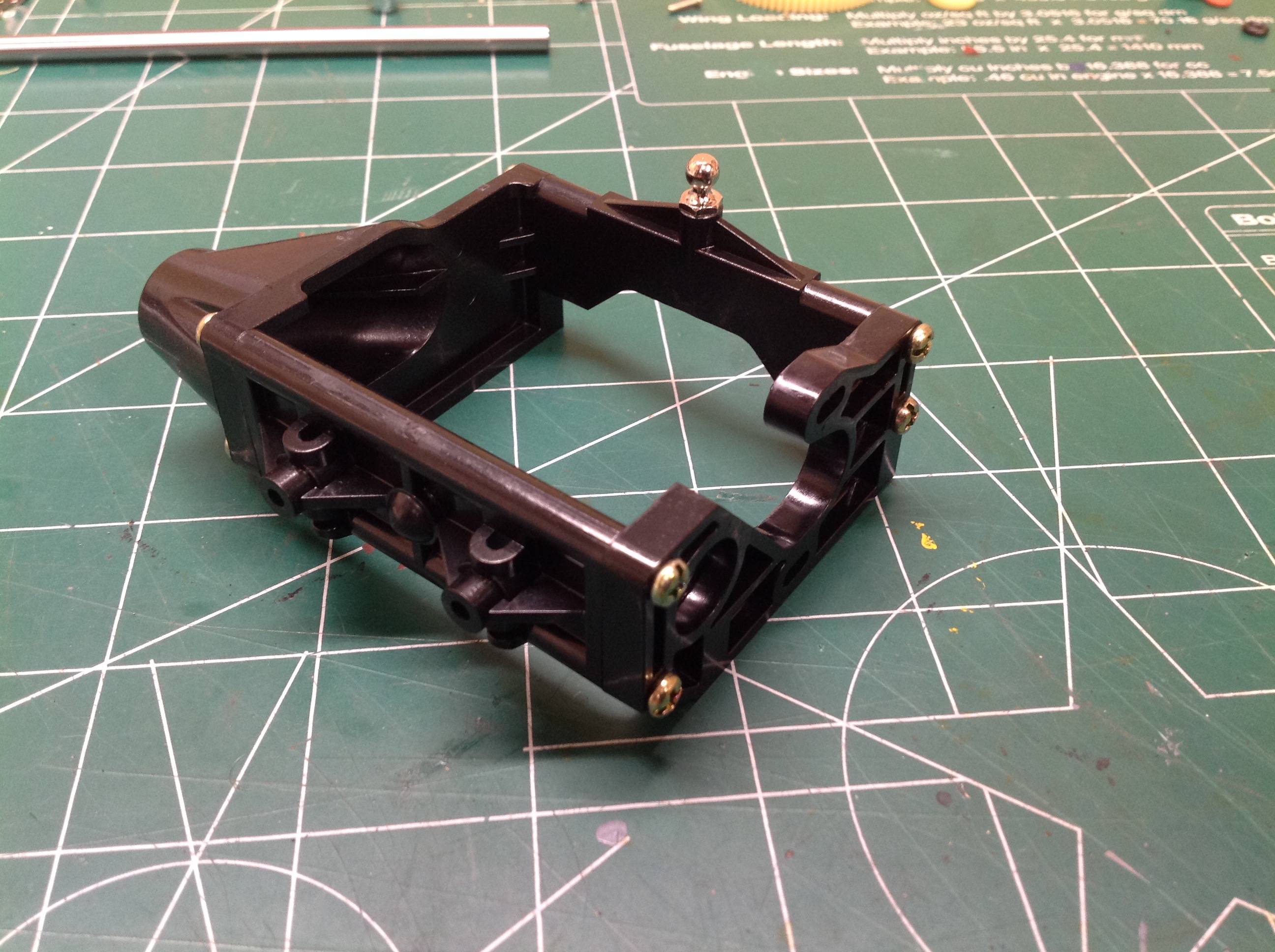
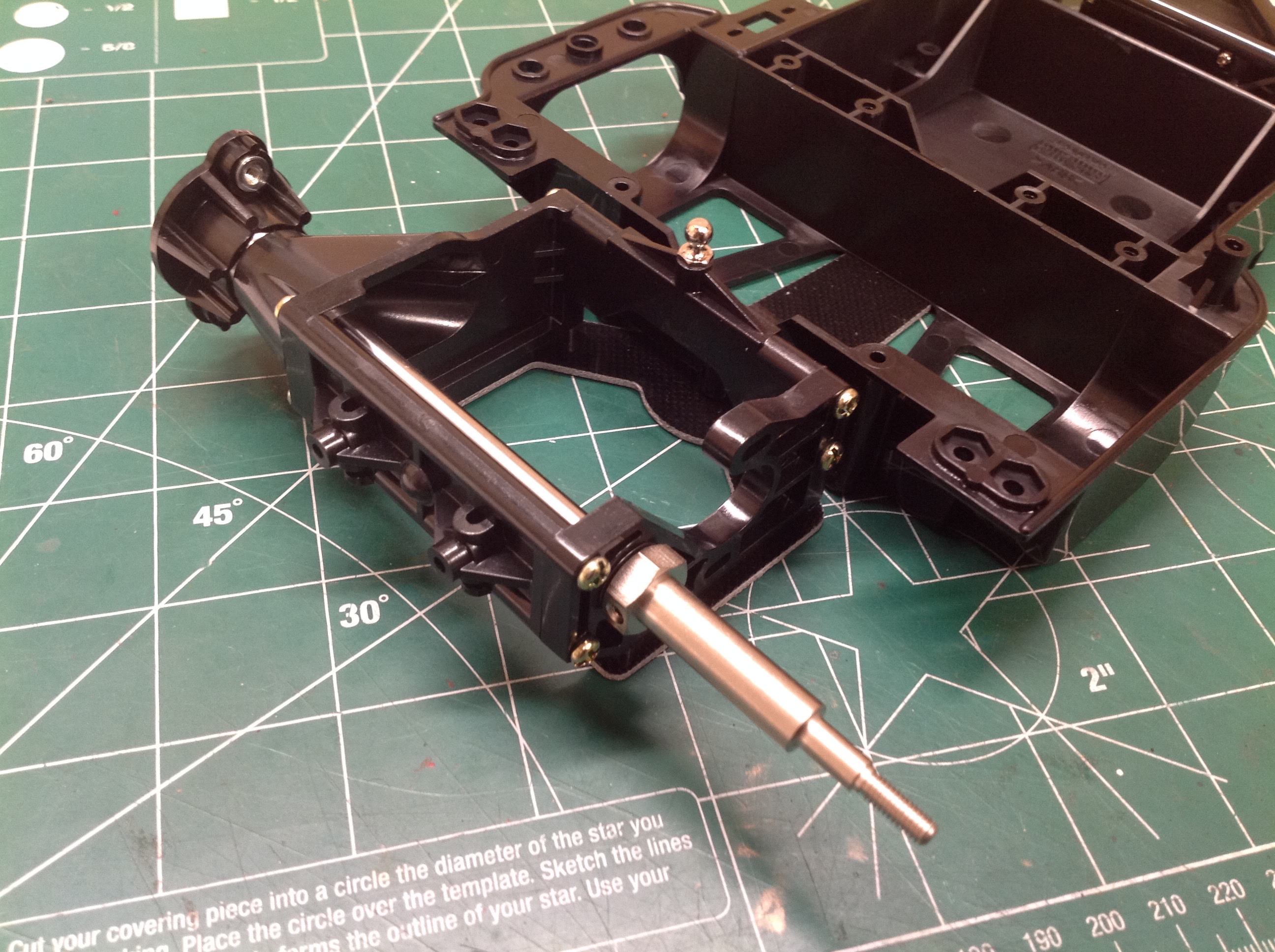
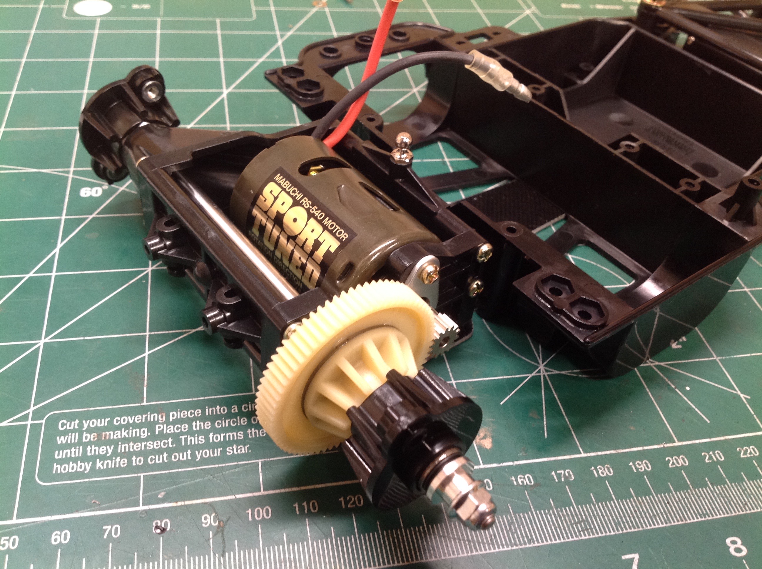
This box houses the gear axle and gearbox (what there is of it).
The slot in the bottom makes room for the motor. The round
protrusion at the left is a bearing support. The ball at the front
center is for the single shock. Note that the shock doesn't do
anything to resist side to side motion. It only responds to up and
down motion which is driven entirely by bending on the rear base plate.
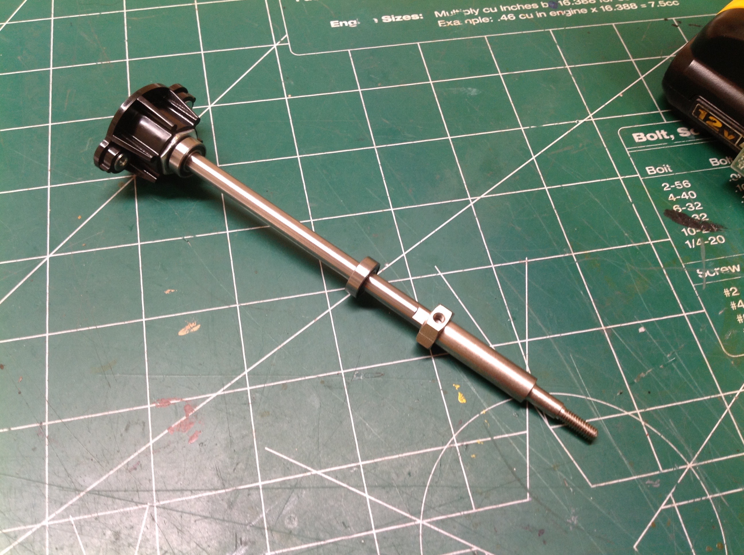
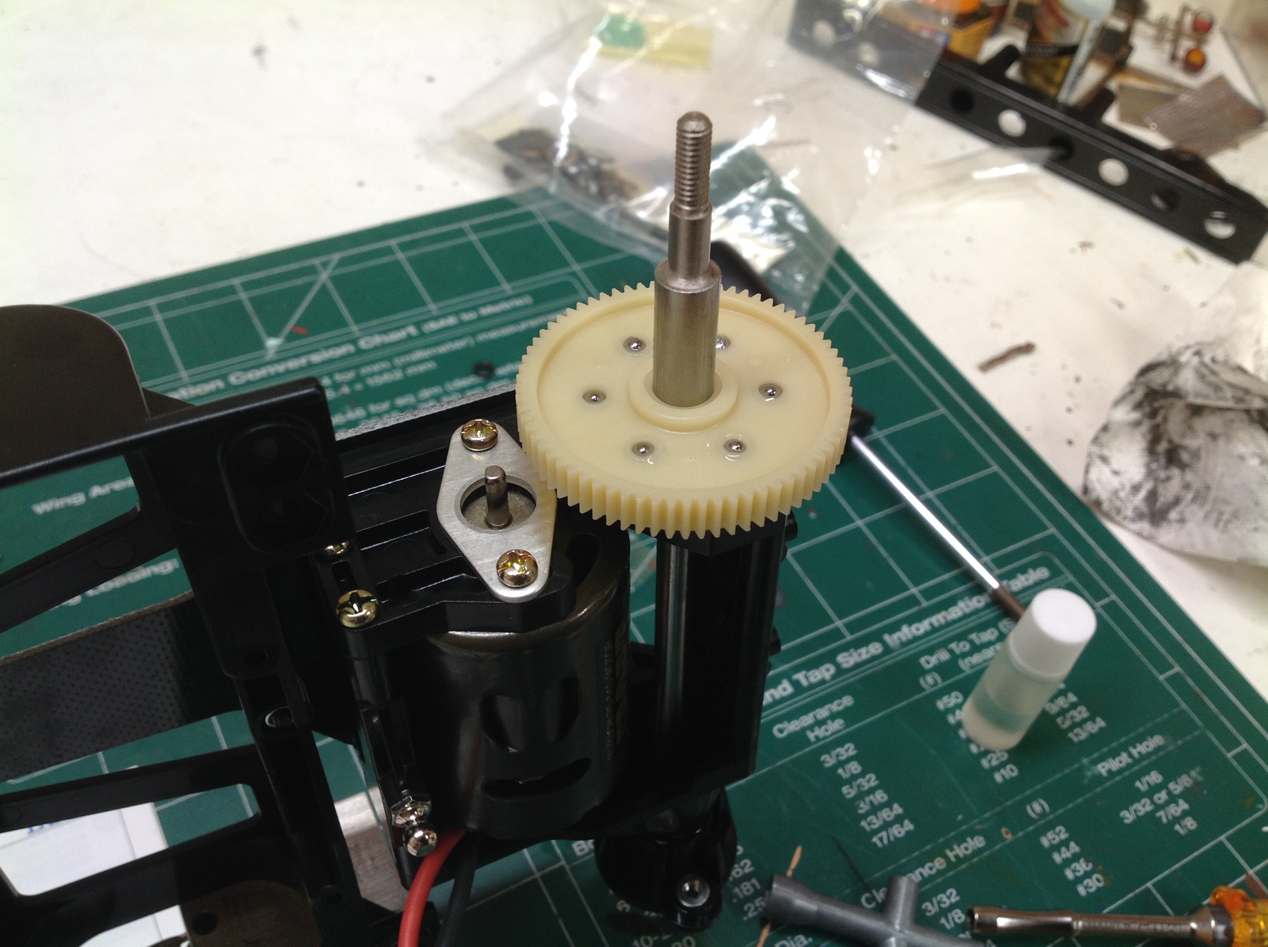
Here's the rear axle. This is a heavy duty shaft inserted from the
left. The plastic hub you see is locked to the shaft and screws
to the wheel. This model does not use hexes to drive the
wheels. The right hand end will serve as the support for the
differential and spur gear.
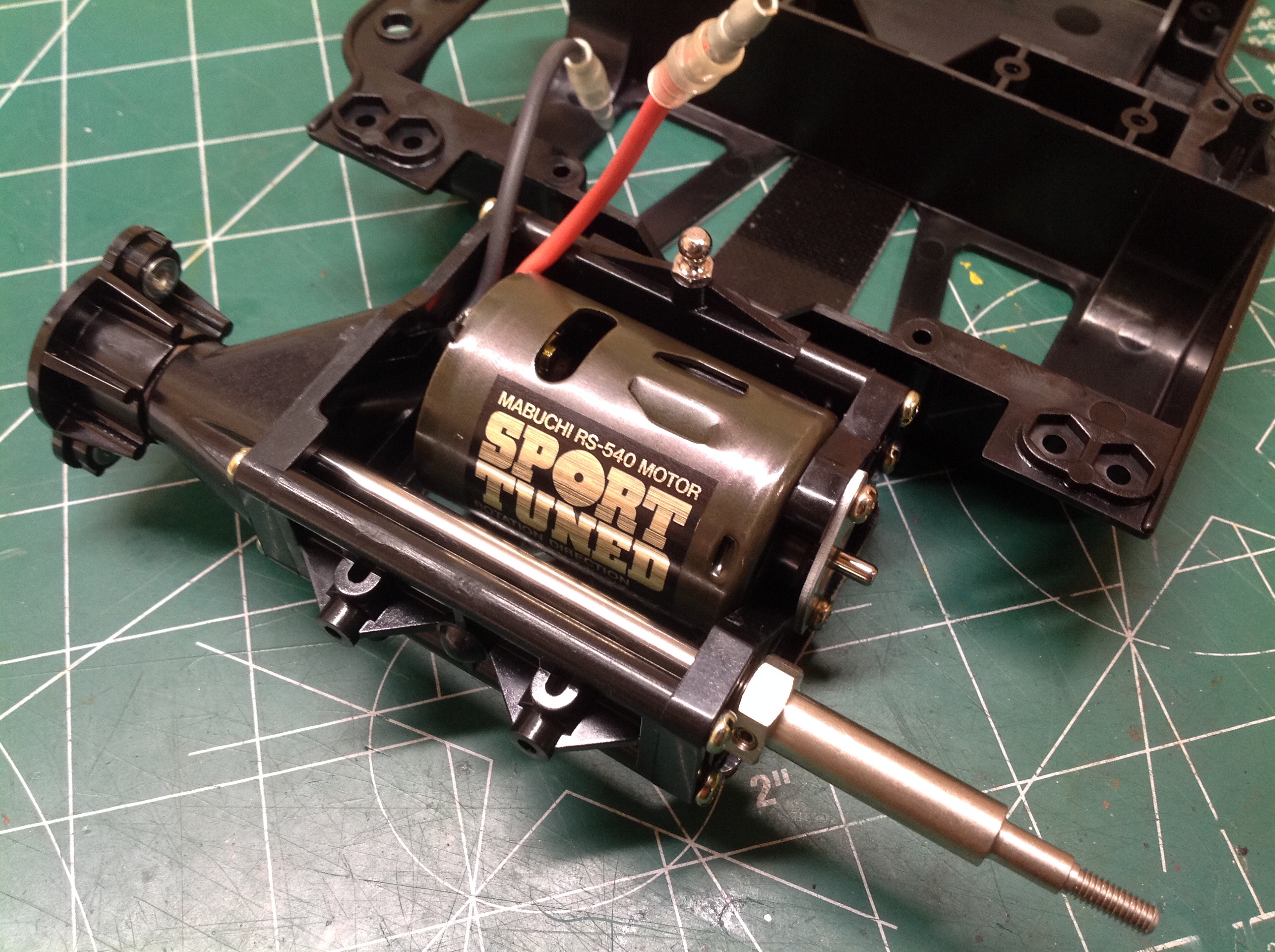
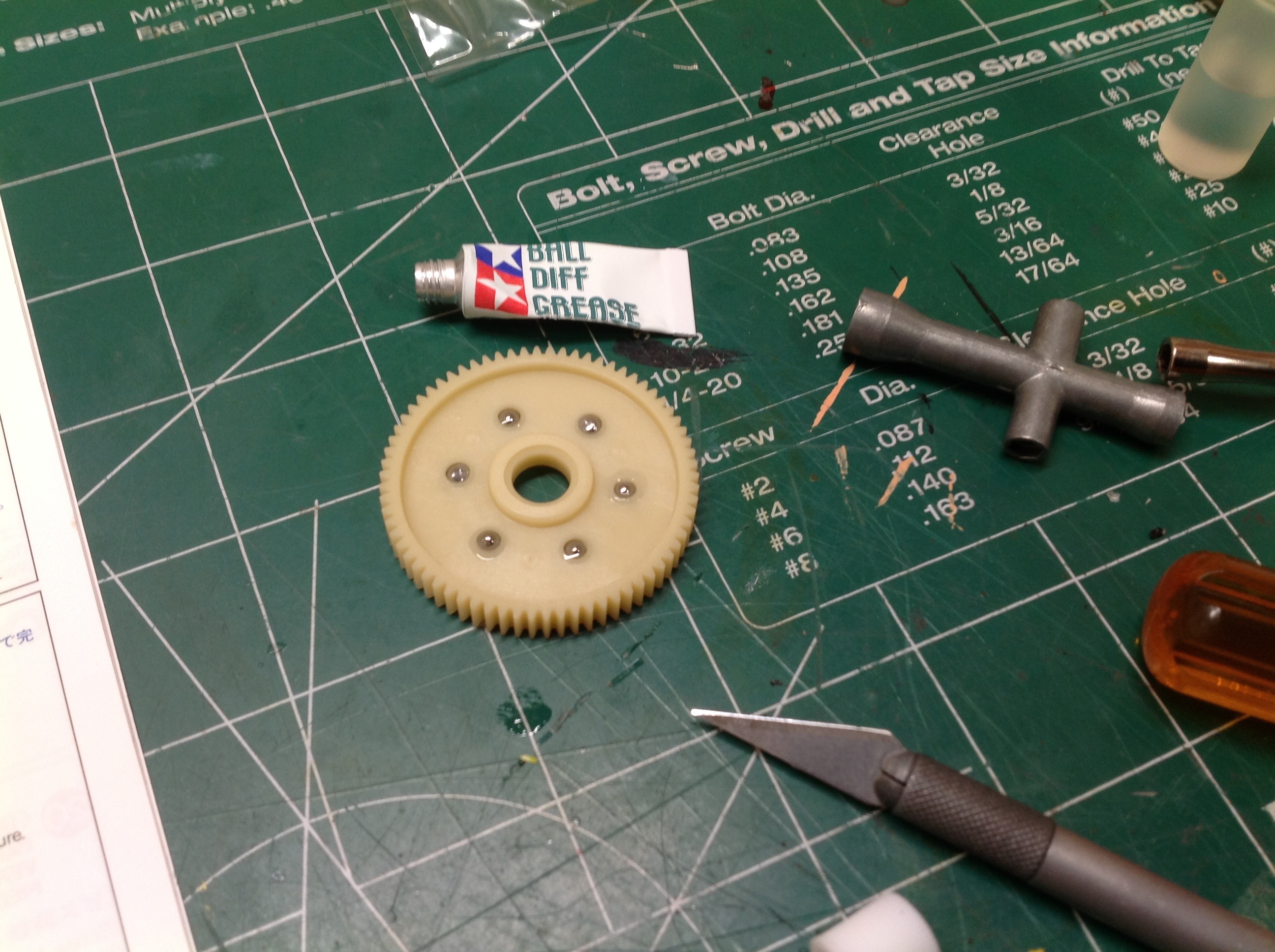
Now the stock Sport Tuned motor has been installed and I've begun
assembly of the ball differential. It uses only 6 small steel
balls carried inside the spur gear itself. These will be
sandwiched between raceway washers.
Now the spur gear has been slid over the axle. It helps to lay the
car on its side when performing this step to allow the axle to be
vertical. The other raceway and hub are then installed completing
the rear axle.
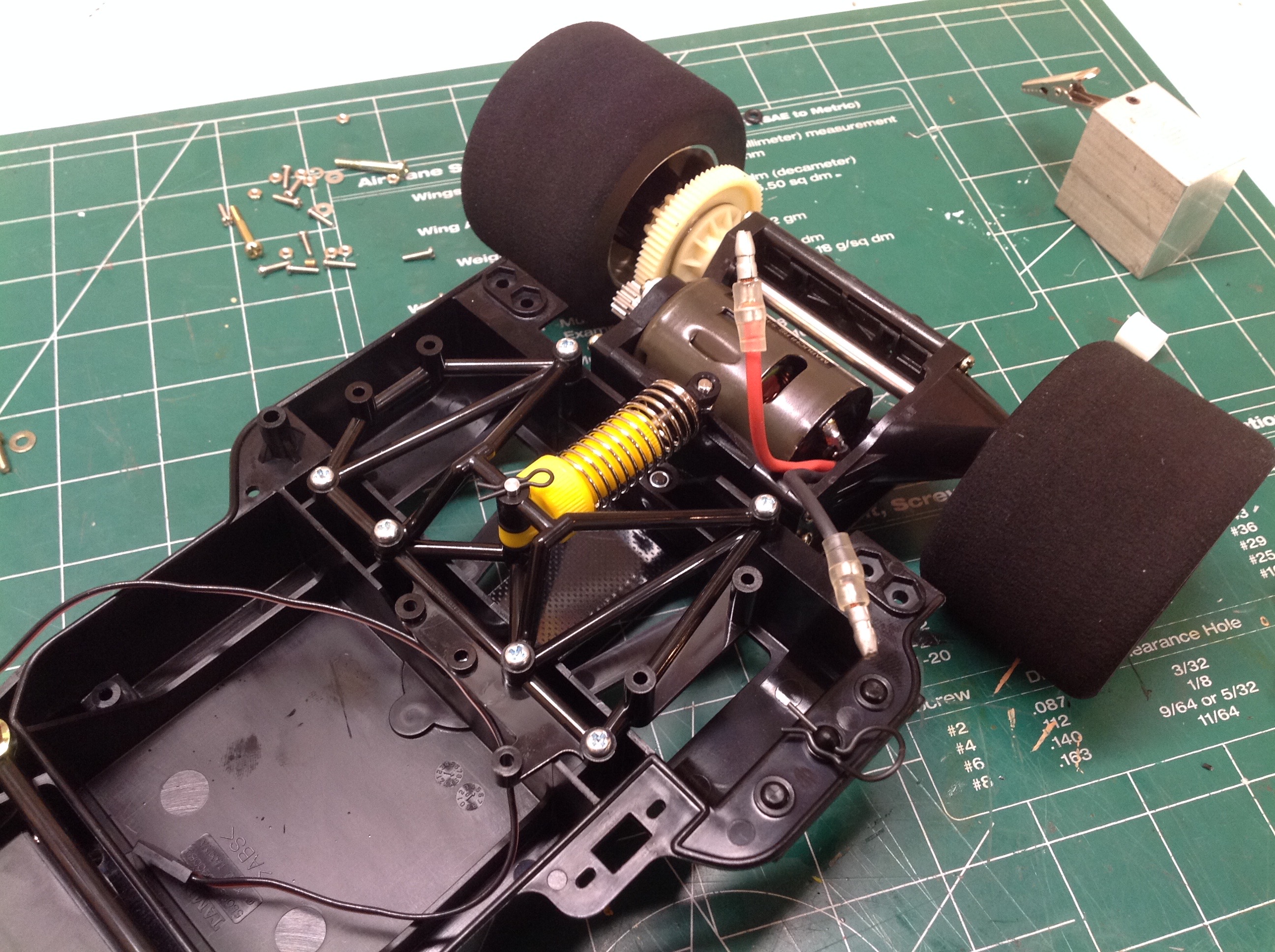
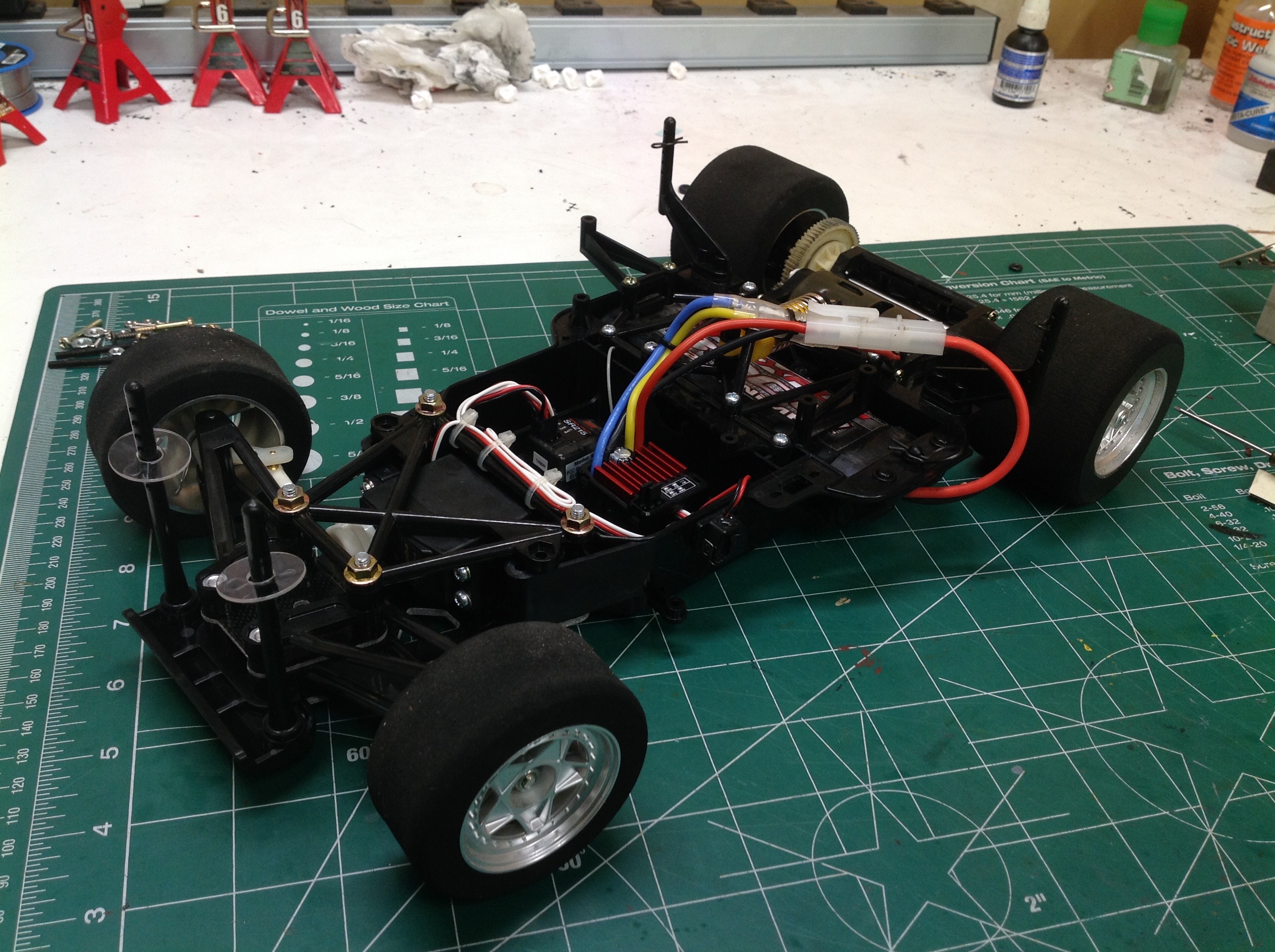
Finally, the single yellow CVA shock can be built and installed and then
the electronics. For some reason I see a standard silver can
motor in this picture, but I have no idea why. I used the Sport
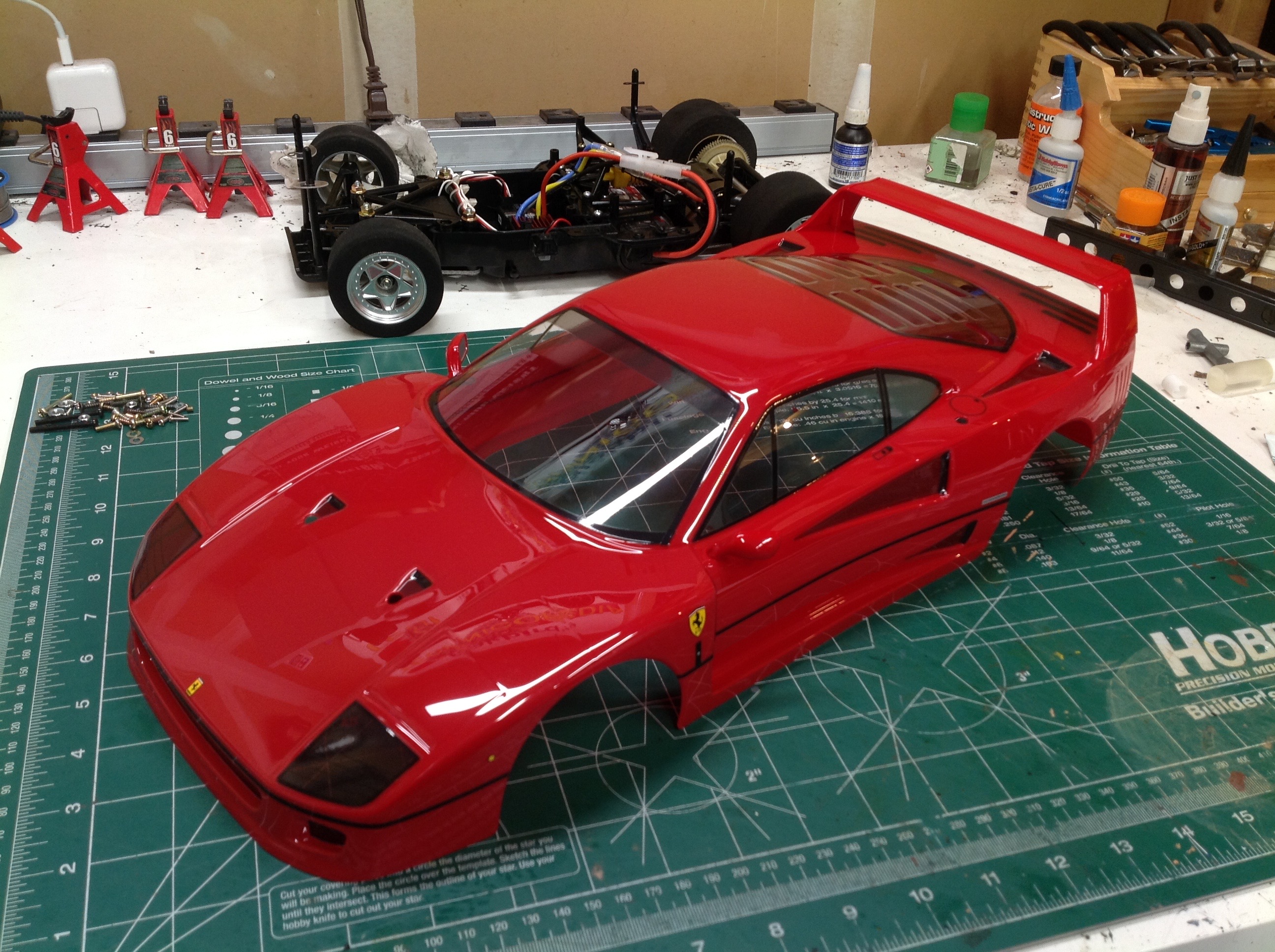
Tuned motor for this build. The right hand image shows the
completed chassis with wheels, tires, and body posts. Note the
extreme width of the rear tires.
Here is the body just as it came out of the box. It has been
trimmed with no burrs, jagged edges, or wavy lines. The paint has
been applied with perfect masking around the windows. The stickers
have also been applied perfectly which is particularly impressive in
the area of the tail lights. My only minor complaint is that the
color of the rear wing does not perfectly match the color of the
body. In fact, it appears that the wing has not been painted as it is
just the color in which it was molded.
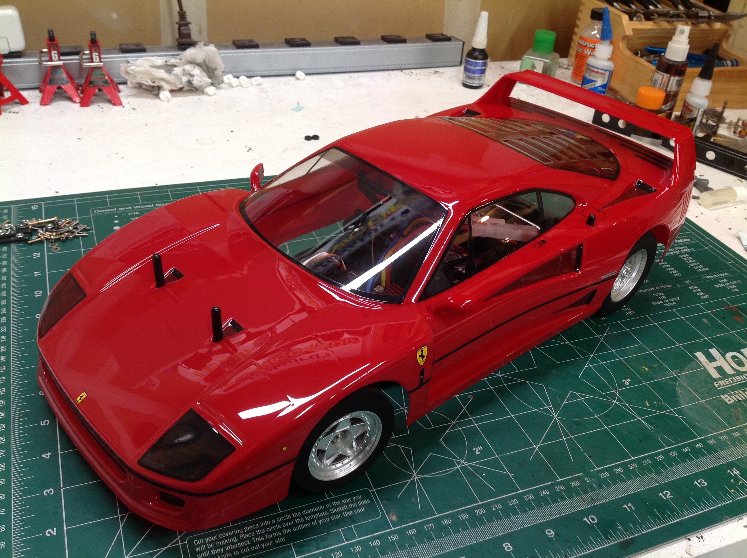
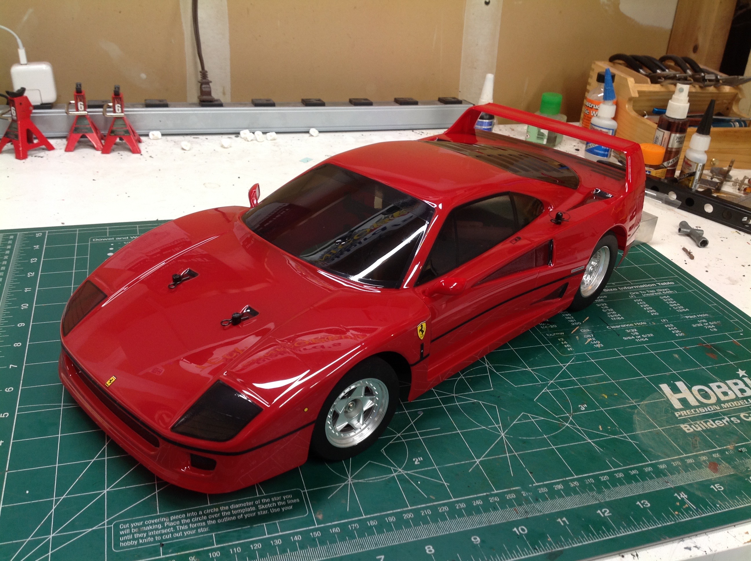
The difference between these two photos is subtle and represents the
only additional decoration I did to the body. I smoked the
windows. I didn't like seeing all the radio gear through the
window and the dark colored windows help obscure that.
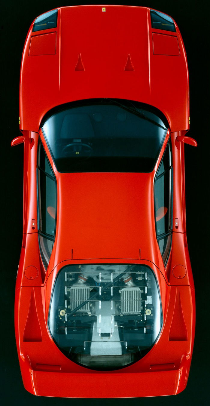
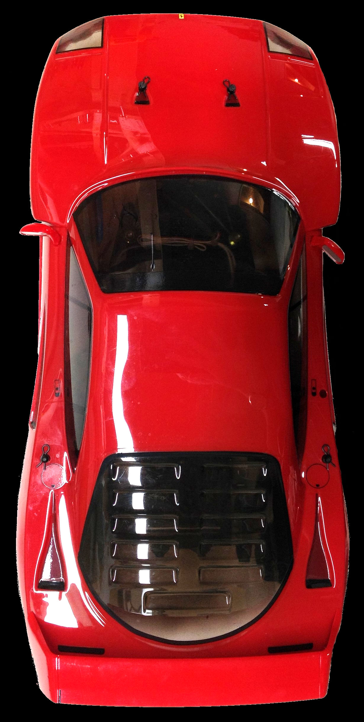
The whole time I've been building, driving, and thinking about this car
I've been concerned that it is not to scale because it is way too wide,
presumably in order to properly fit the Group C chassis. To prove
this I found an overhead view of the real car and compared it to a photo
I took of the model. Looks like I was wrong; the F40 really is
this wide.
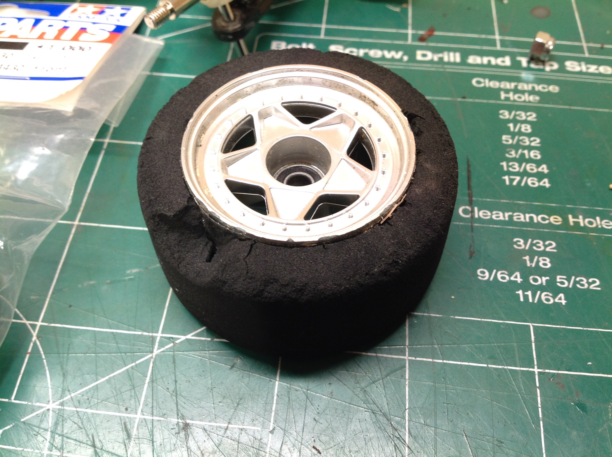
This shows the damage to one front tire after the first run. The
combination of cracking caused during tire installation combined with
the kingpin coming loose and canting the wheel caused a lot of
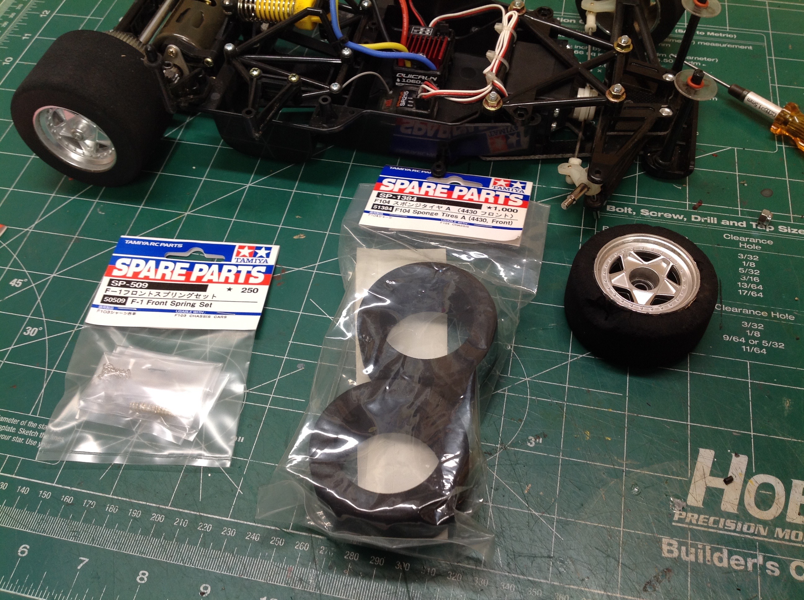
damage. The tire part number listed in the manual doesn't seem to
exist any longer, but luckily I found that the front tires for the F104
chassis fit just right, and now that I know how to install them I did it
properly.
©2019 Eric Albrecht