Tamiya FF-03 Project
Page 3: FF-03 EVO
The EVO is the model I actually wanted to build when I started this
project. All the other variants just came along with the
purchase. I consider the EVO to be the ultimate incarnation of the
FF-03 (although the upgrade kit is a close second). I started by
building the EVO in a completely stock configuration which is what I am
documenting here.
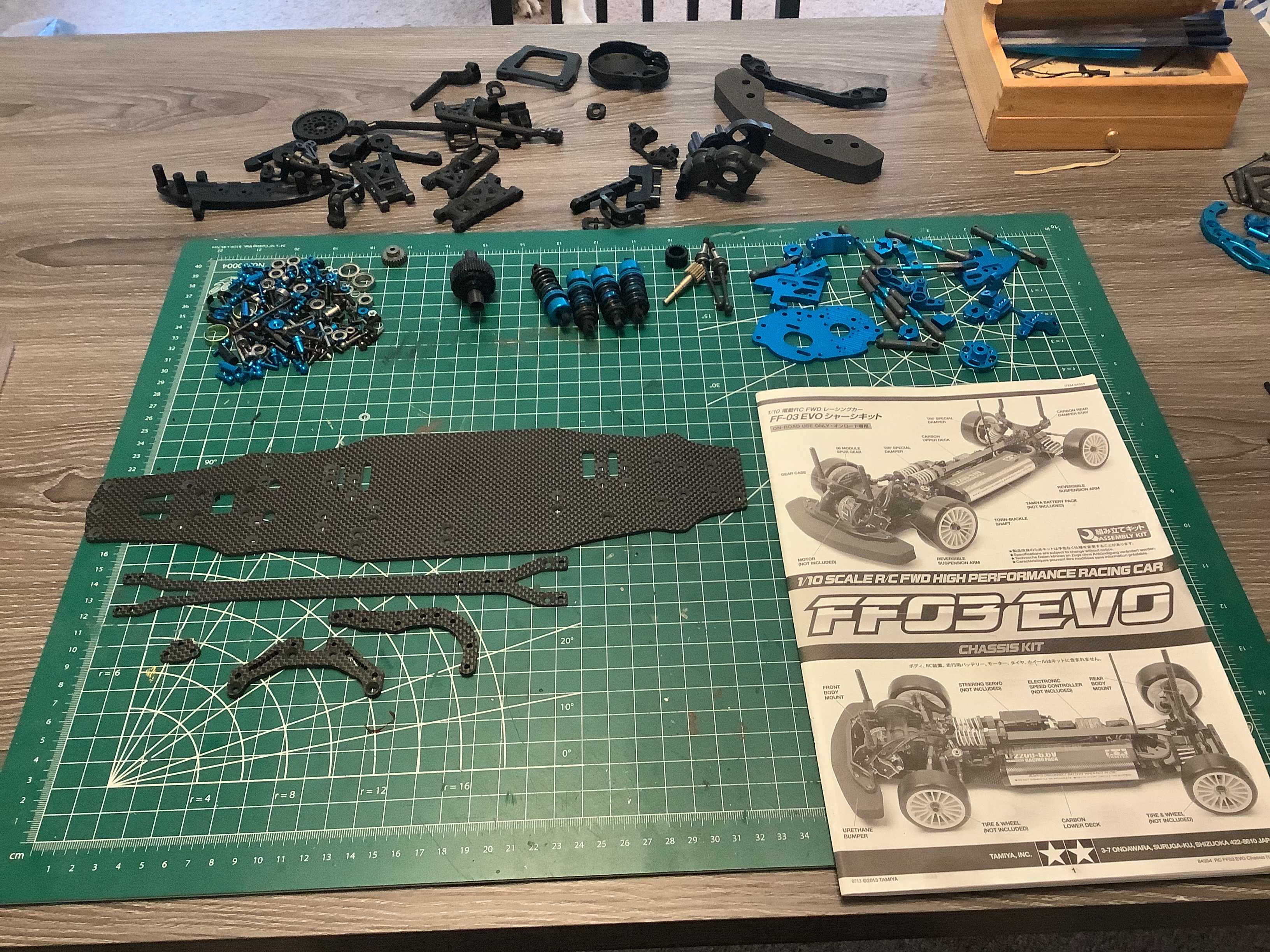
The model arrived assembled so I started by completely stripping it down
to kit form as shown. There actually aren't very many parts in
this chassis given that it has only one gearbox and differential, and
very little of it is plastic. Carbon fiber and anodized aluminum
are well represented here.
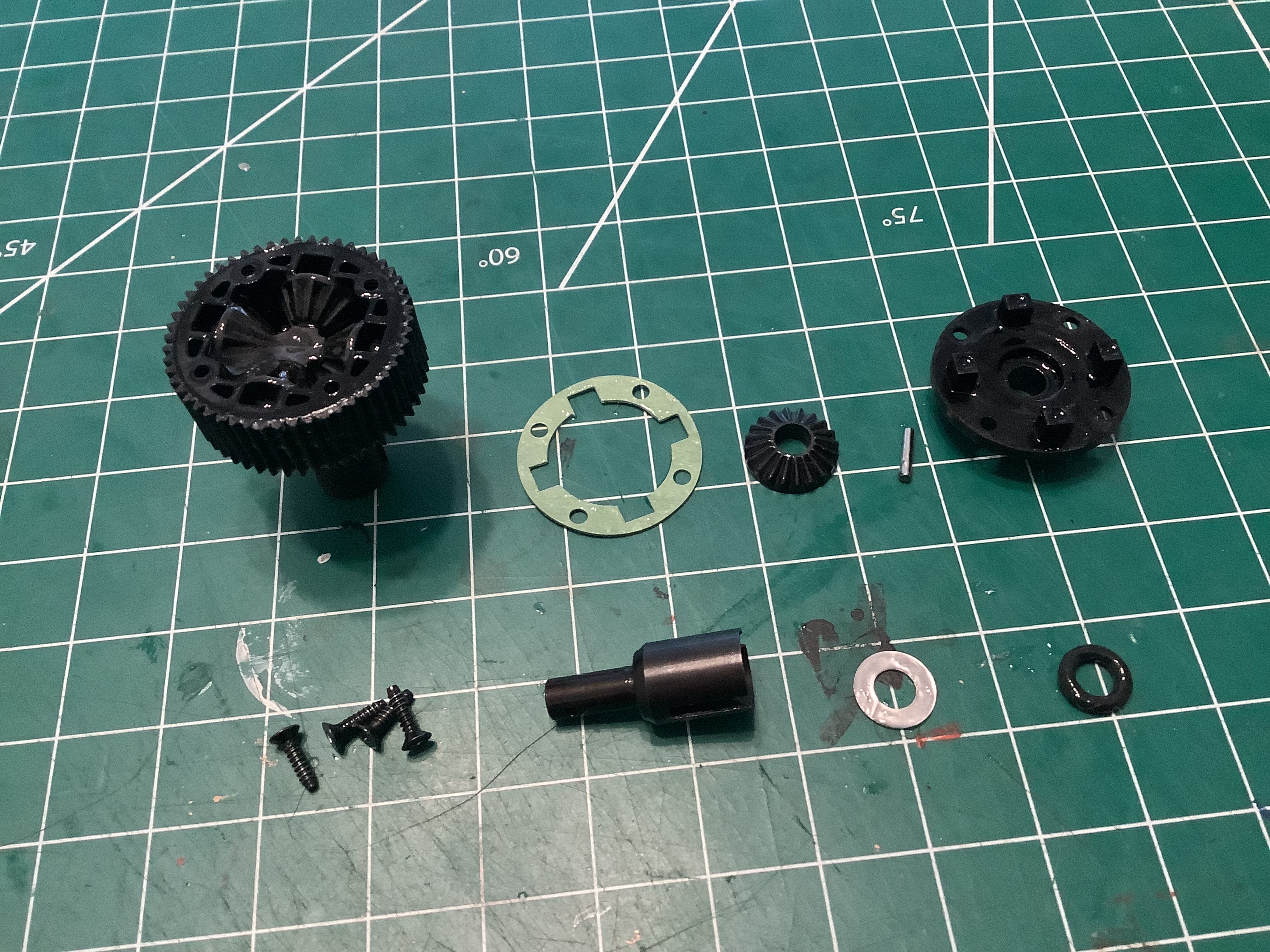
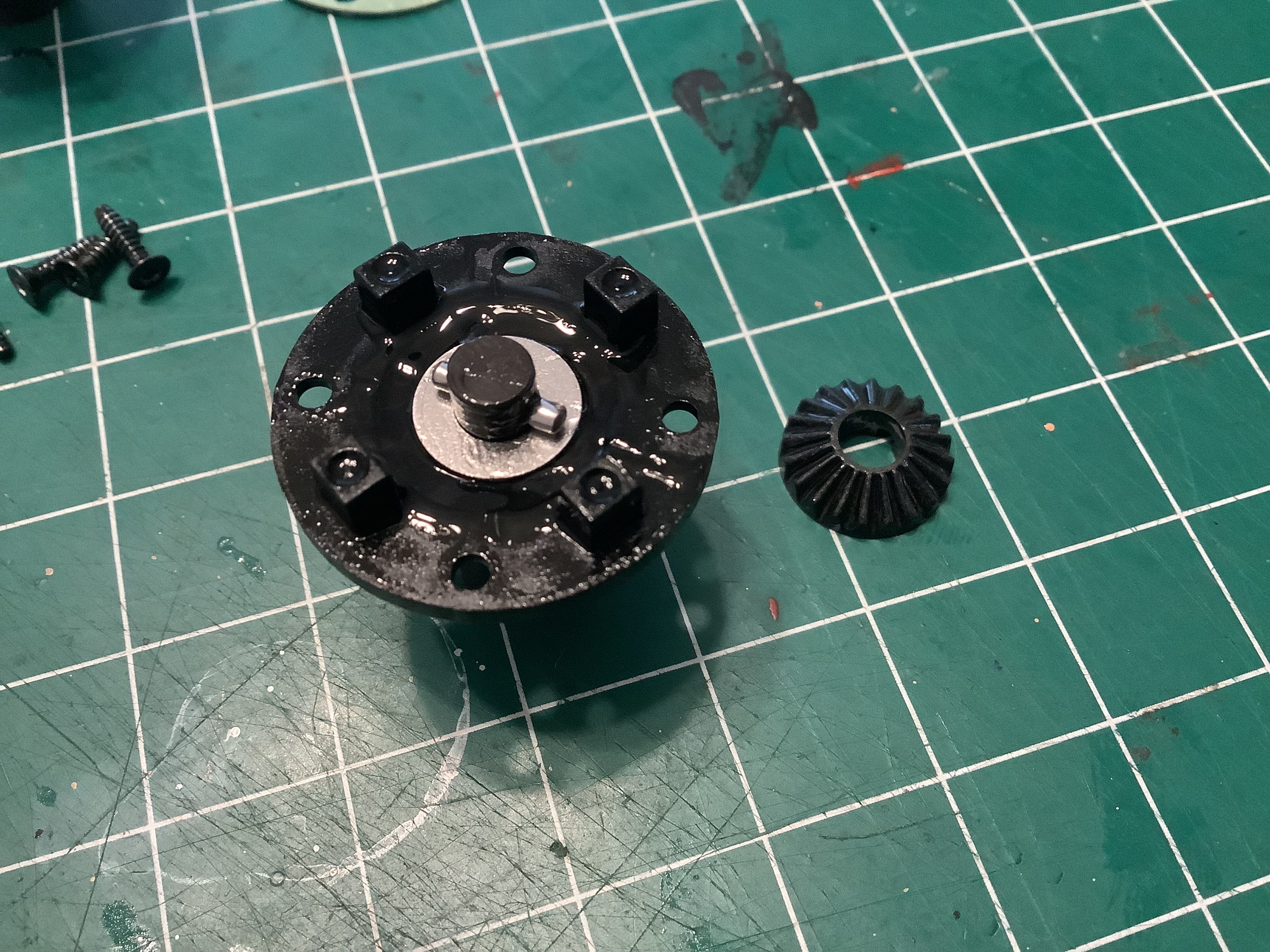
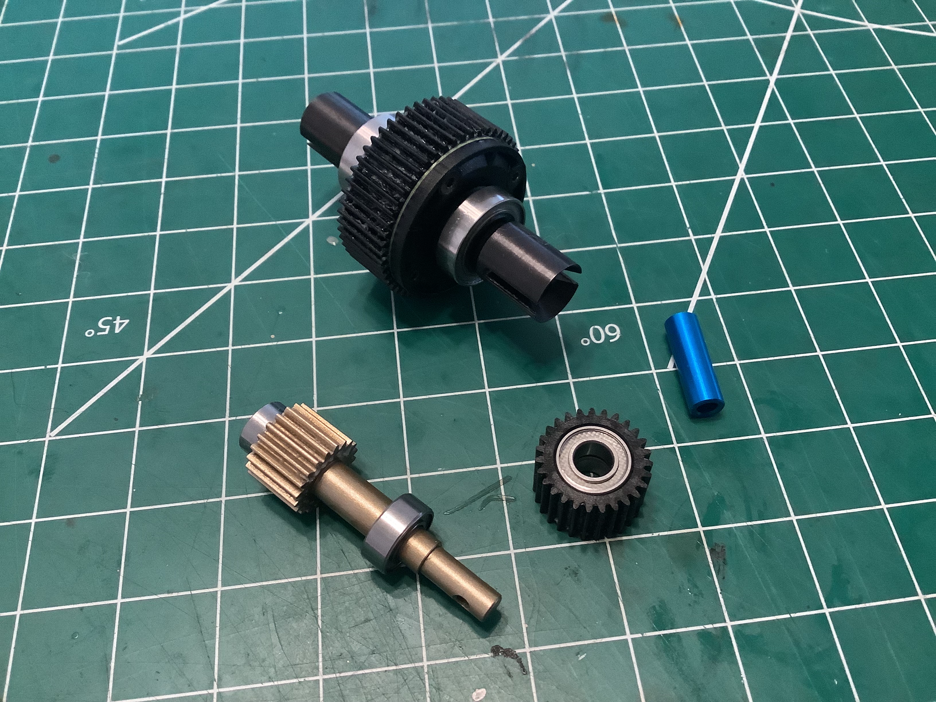
Unlike the standard variants of the FF-03, the EVO uses a sealed gear
differential instead of a ball differential. The internal gears,
including the 4 spider gears, are all reinforced plastic. The
drive cups are sealed with o-rings and then the housing is filled with
extremely thick #100000 silicone oil that appears to be unique to FWD
models. This viscous fluid resists, but allows, differential
motion of the axles.
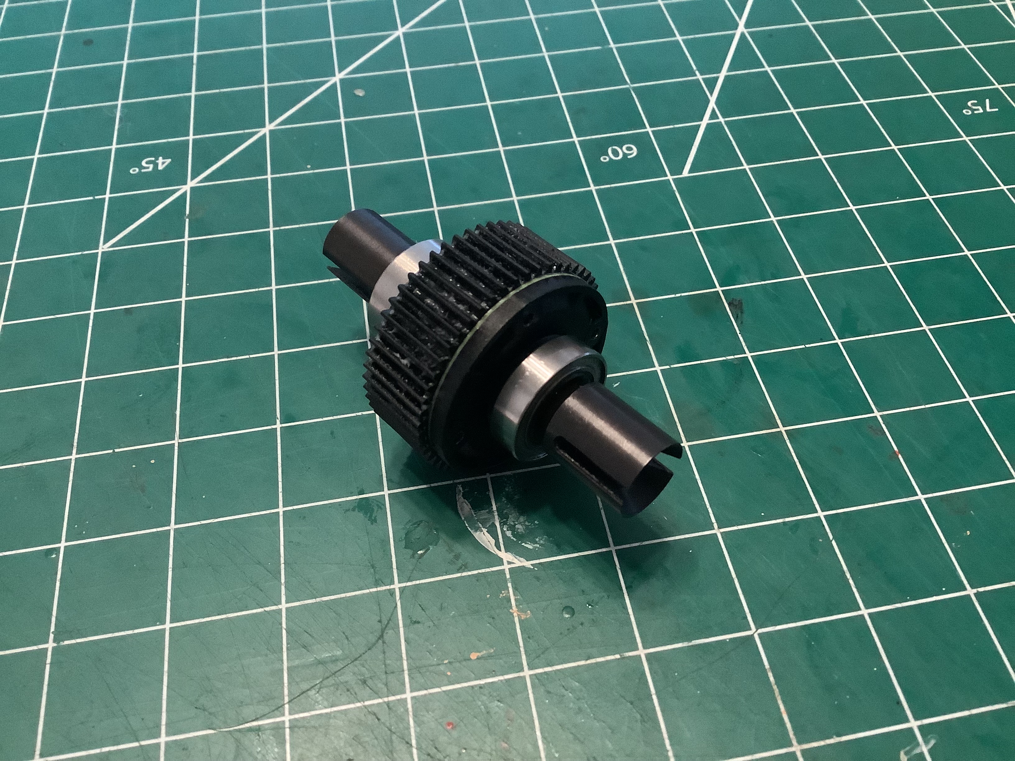
Here is the completed differential along with the other components of
the gearbox. The spur gear shaft appears to be hard anodized
aluminum with an integral gear for minimum rotating inertia. The
idler gear is plastic and rides on a blue anodized aluminum shaft.
All rotating parts use special low friction fluorine coated sealed ball
bearings.
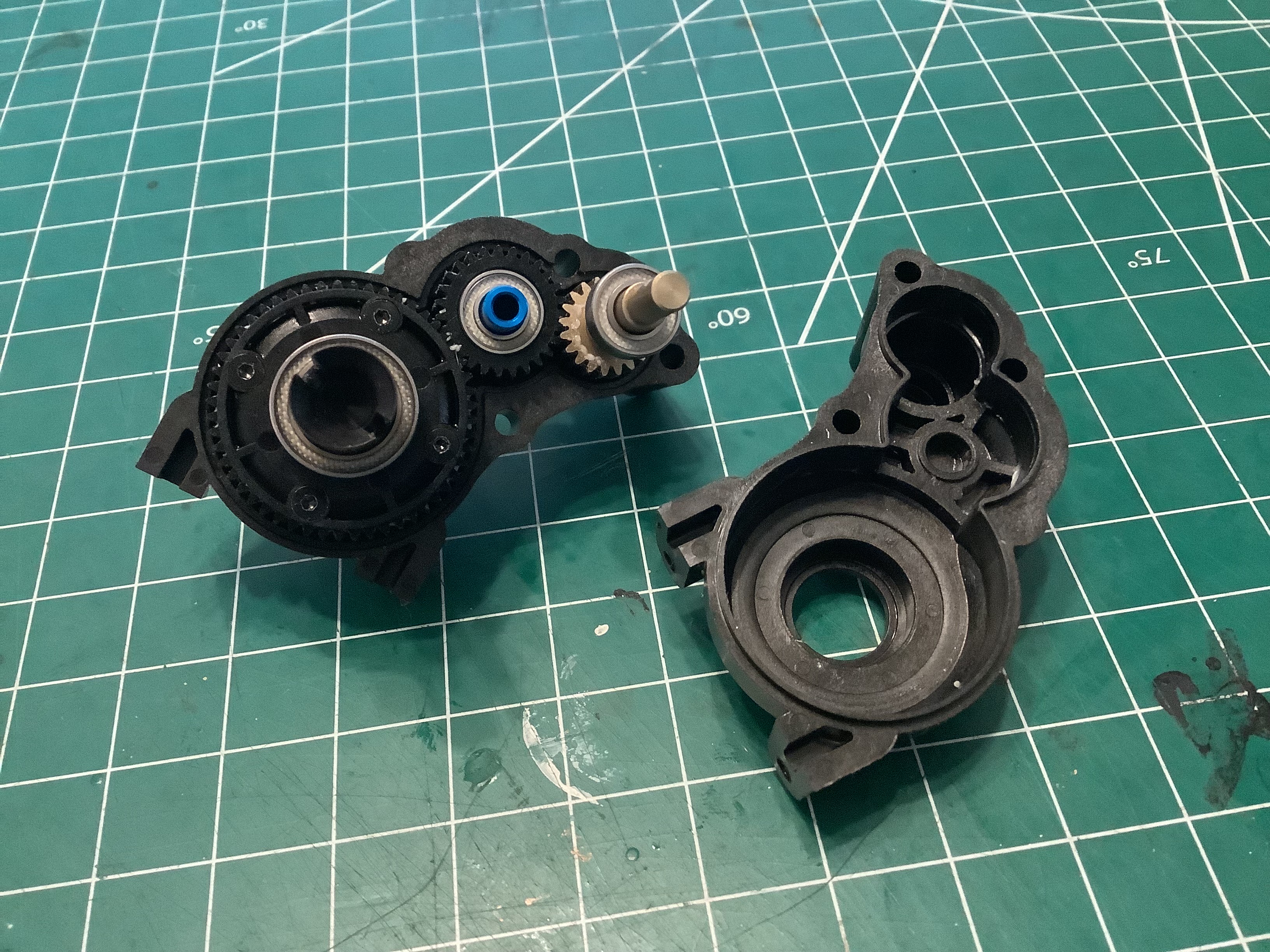
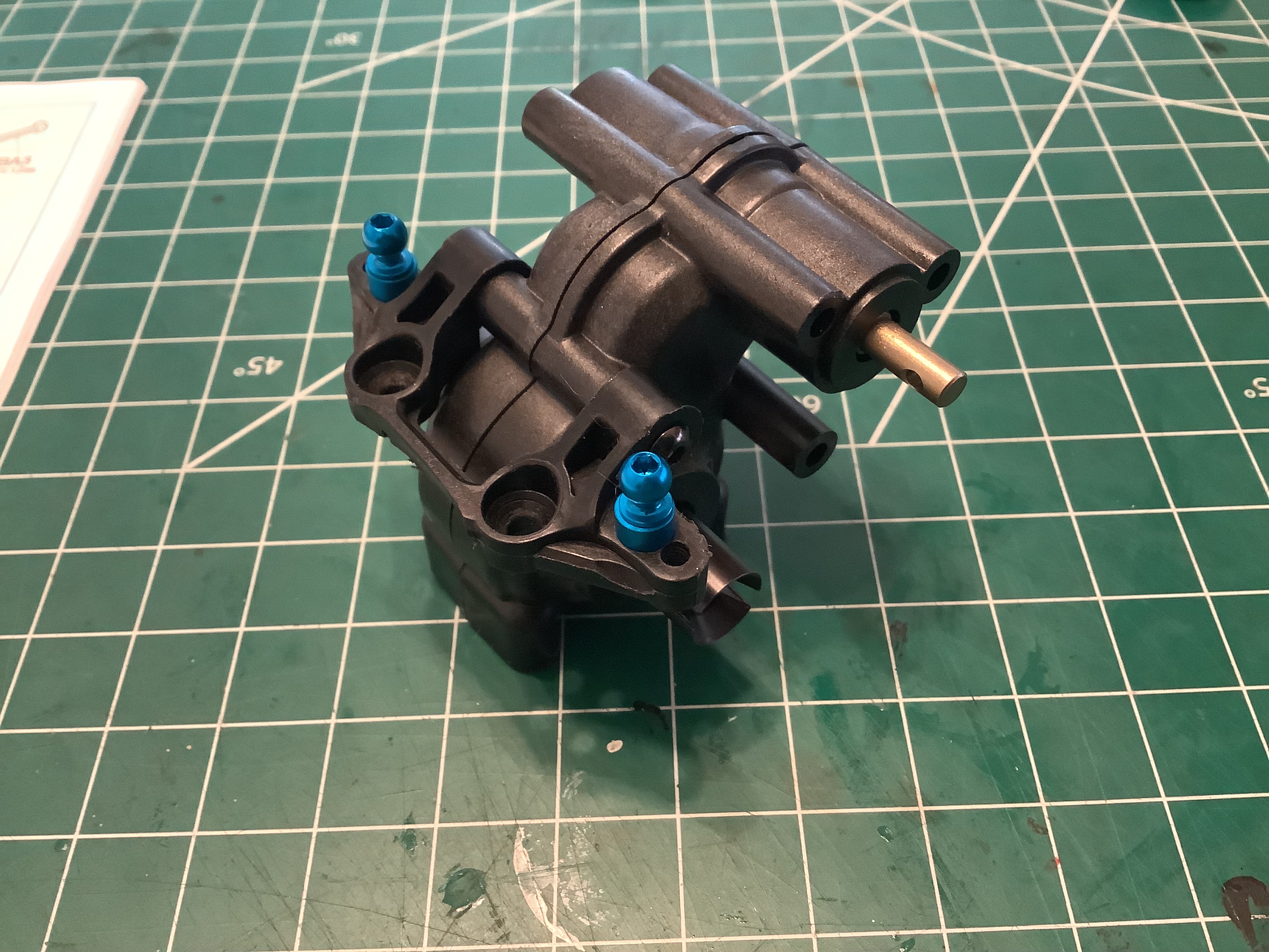
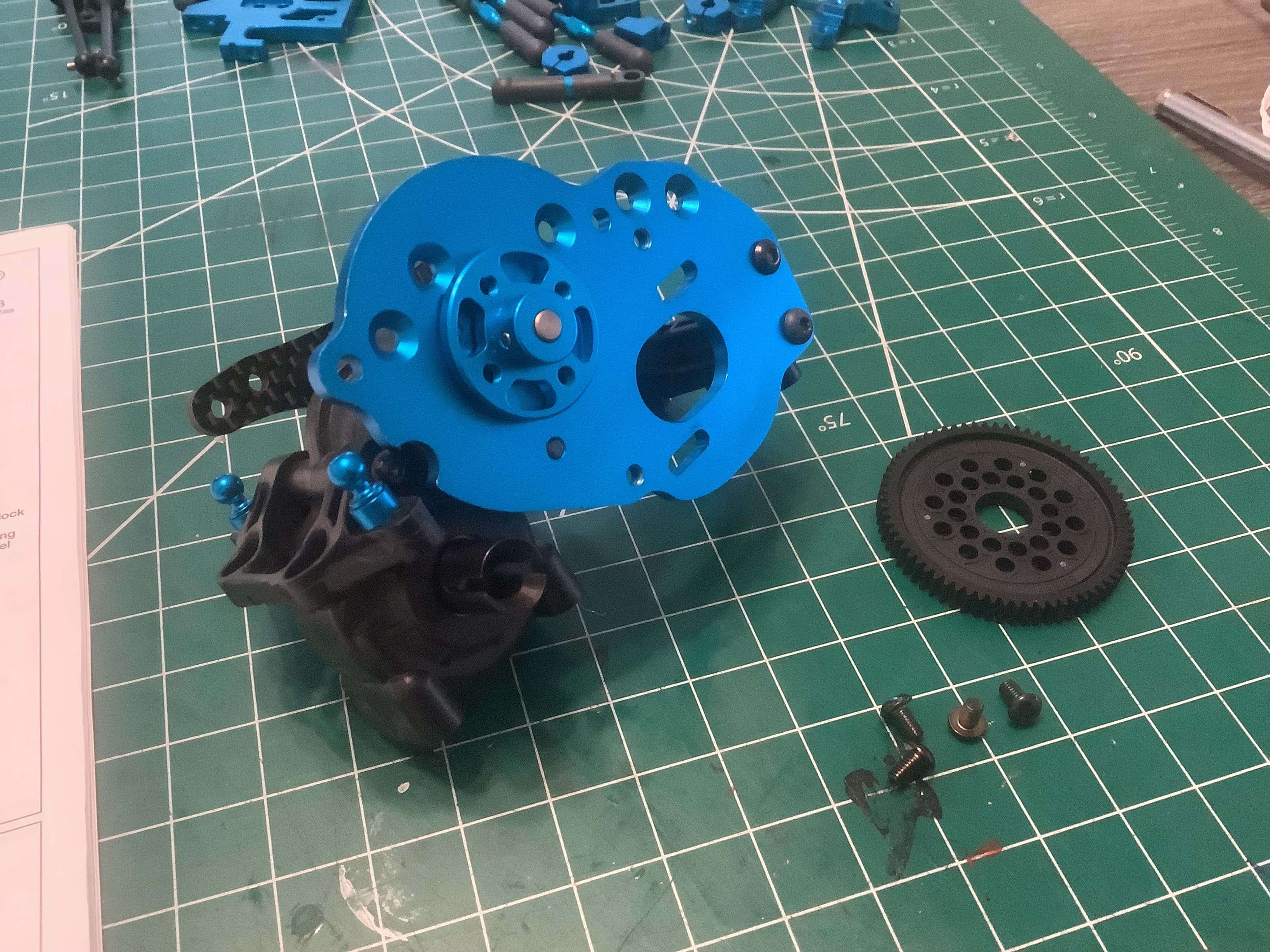
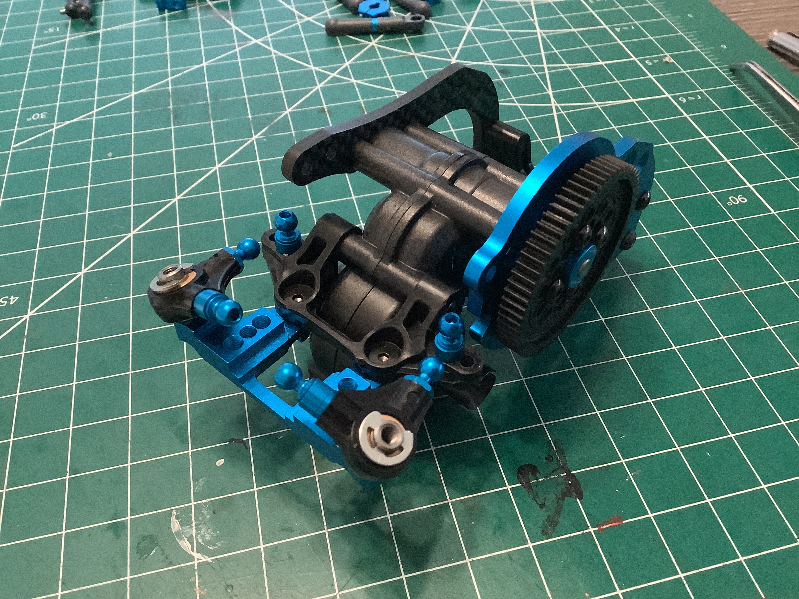
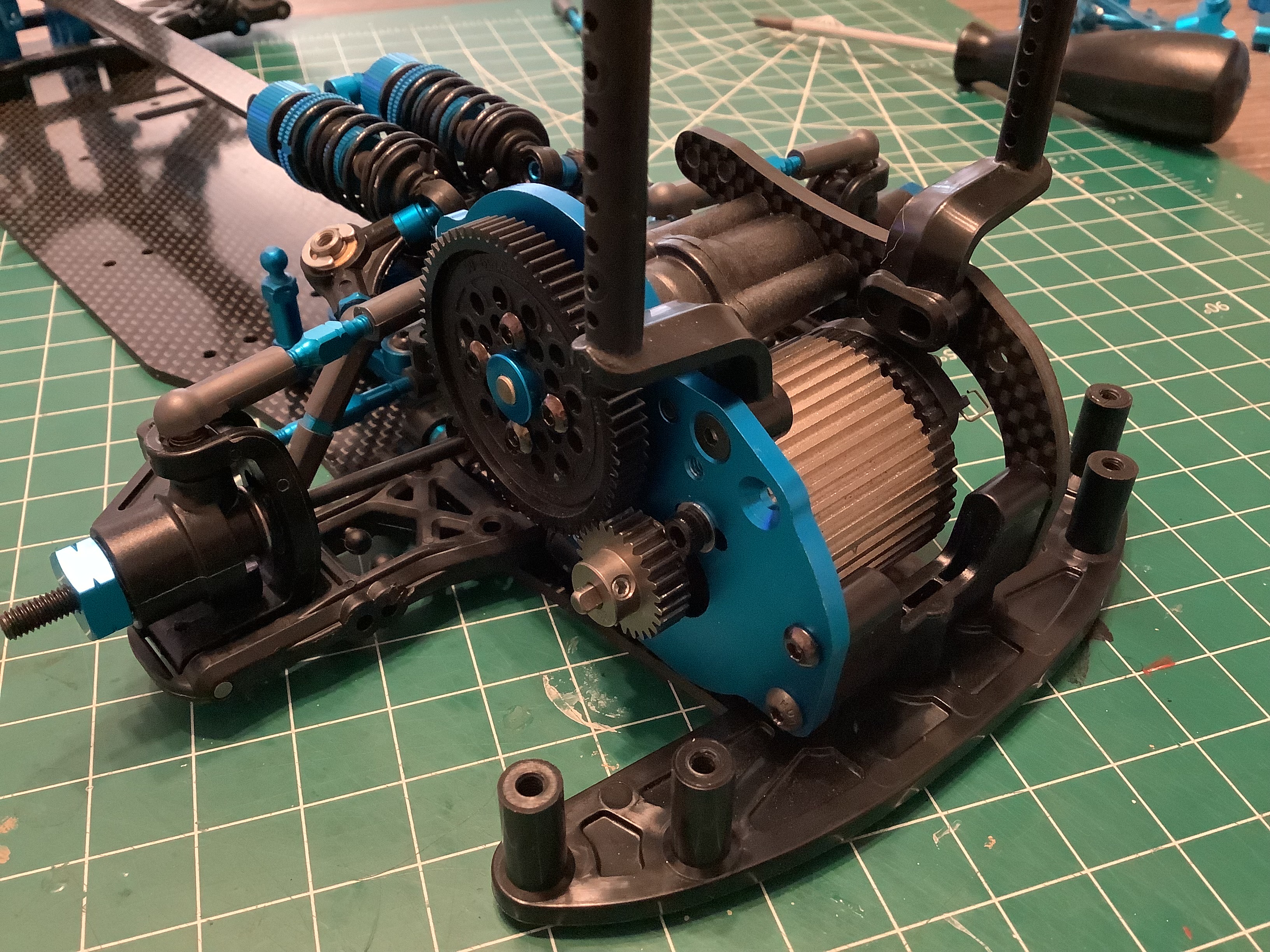
Now the gears can be added to the reinforced gearbox housing as
shown. The front upper arm mount has been added on the right along
with the long aluminum ball connectors and aluminum spacers. All
the parts on this kit are so nice.
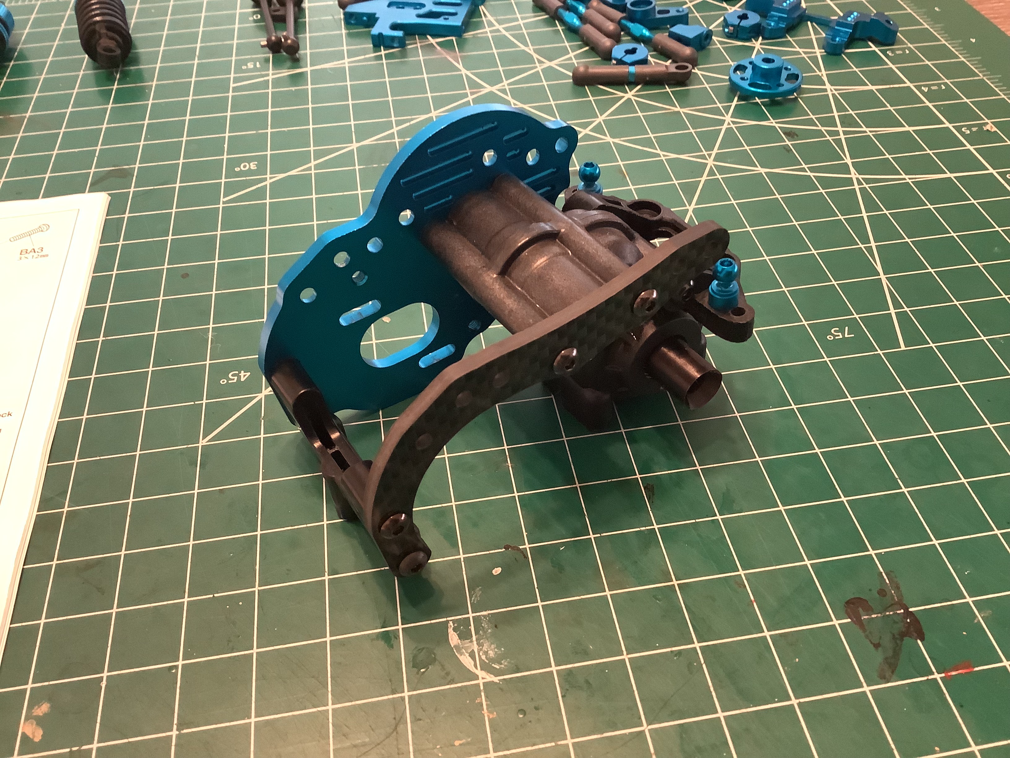
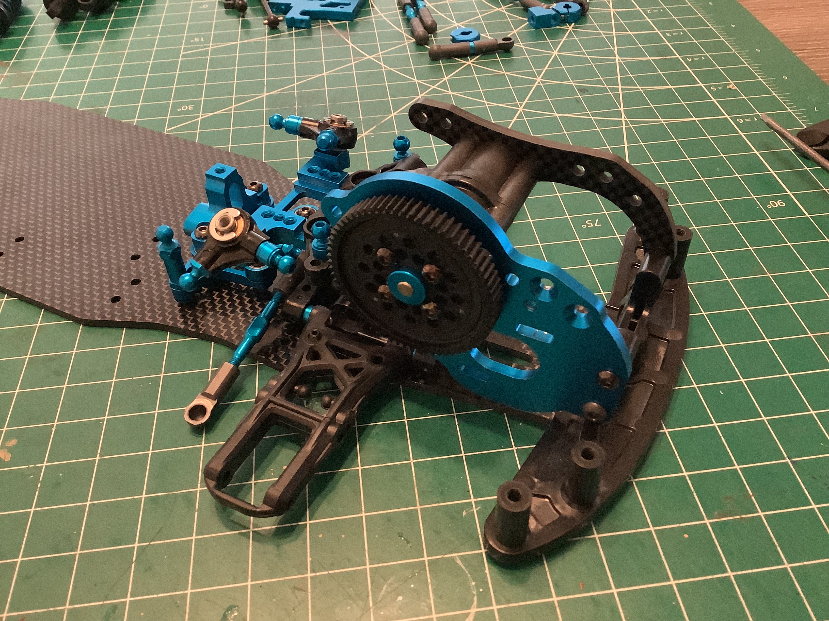
The EVO uses an anodized aluminum motor mount with machined heat sink
pockets and a carbon fiber motor stay. All of hardware is hex
drive instead of JIS including the rare 3x48mm button head cap screws.
The spur gear mount is also aluminum but gets mostly hidden once the 68T
0.4 mod spur gear is installed. The motor sits ahead of the axle
for maximum weight over the front wheels.
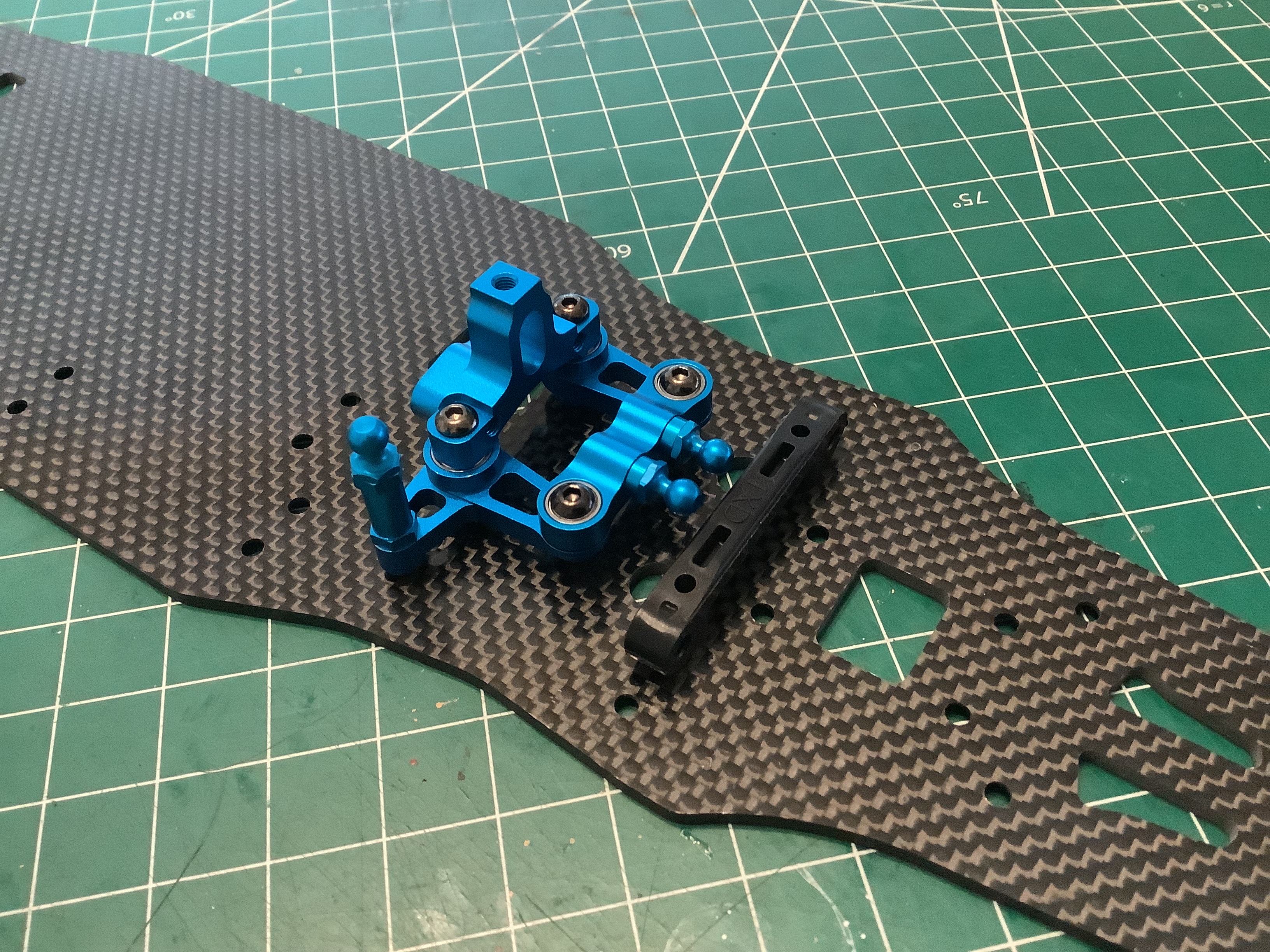
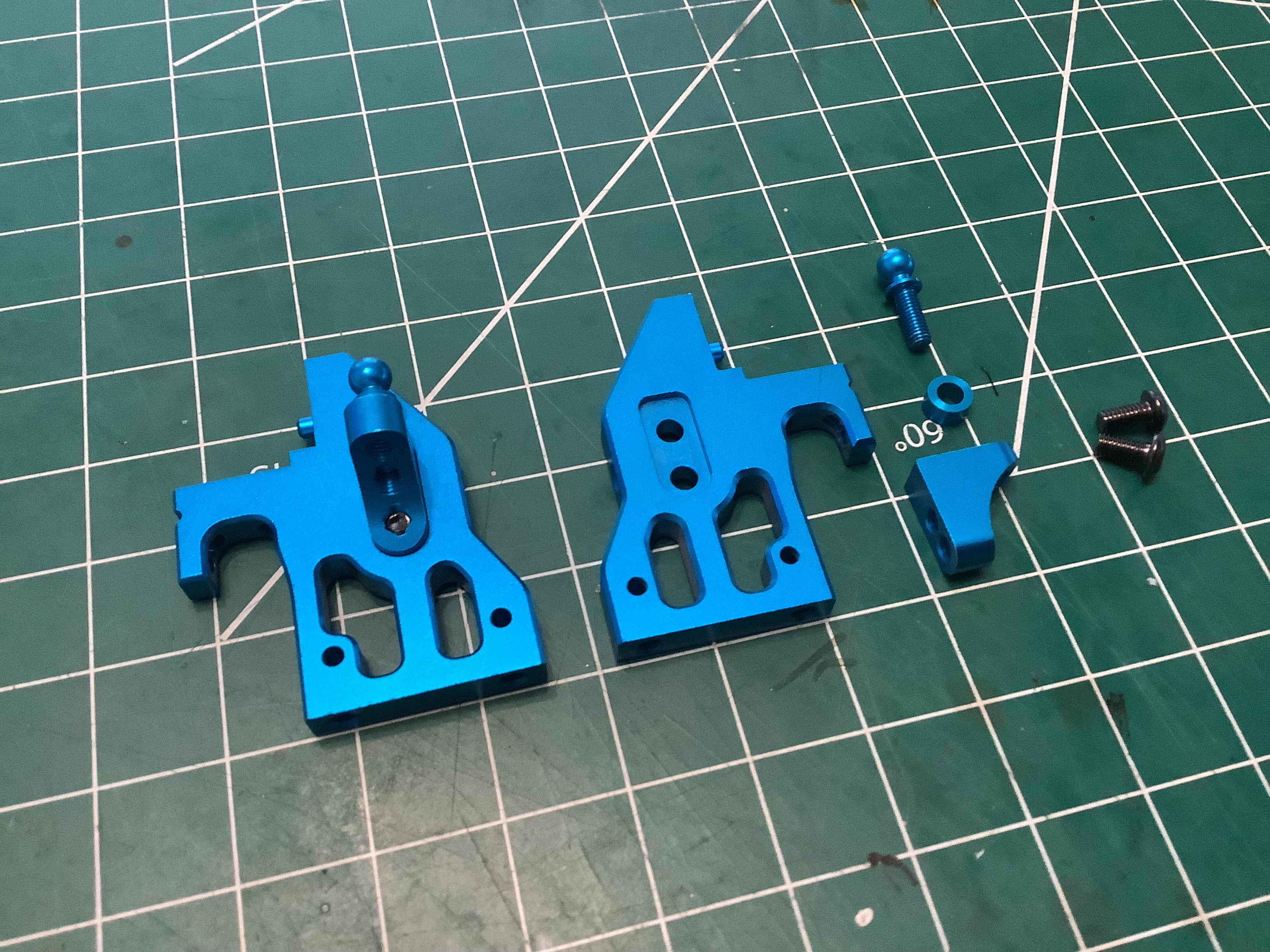
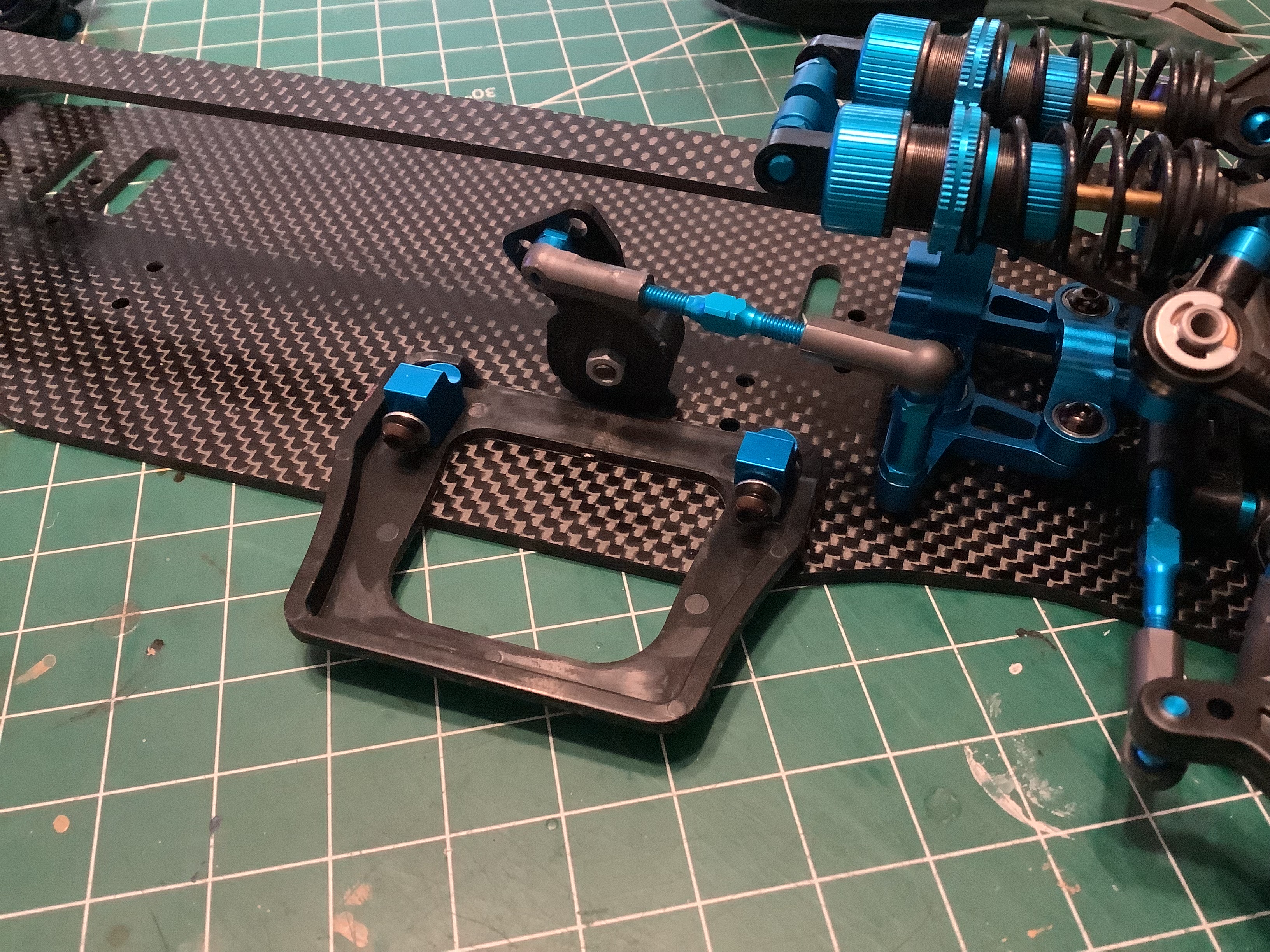
The bracket for the inboard front suspension is machined, anodized
aluminum and supports the pivots for the suspension cranks. The
cranks are plastic but each use 2 additional aluminum ball ends and
spacers. All of the front suspension forces pass through this
assembly which will also serve as the attachment for the carbon upper
deck.
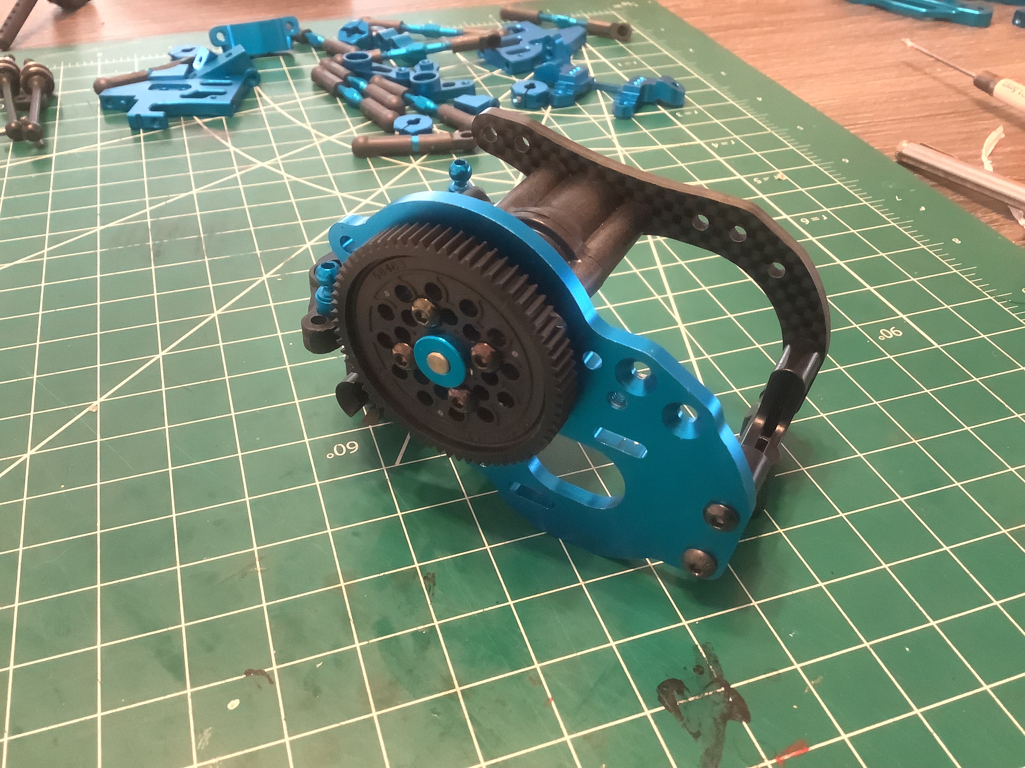
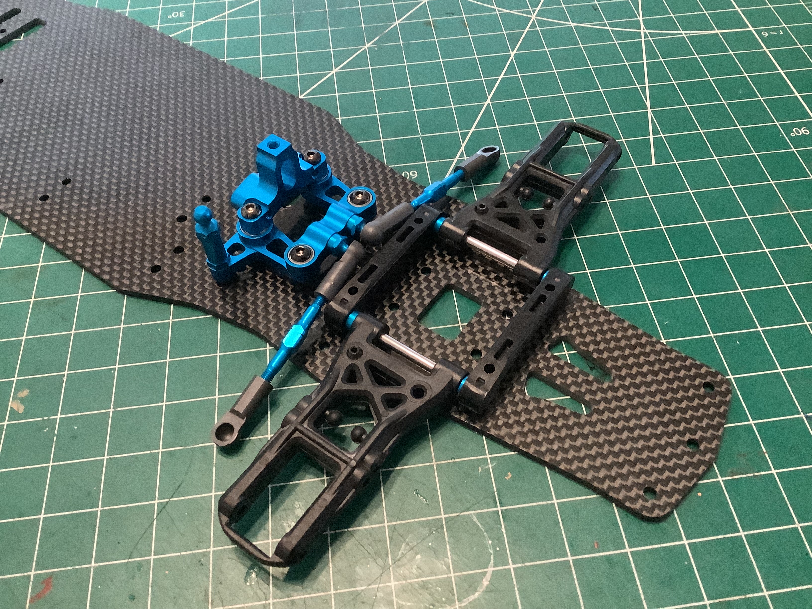
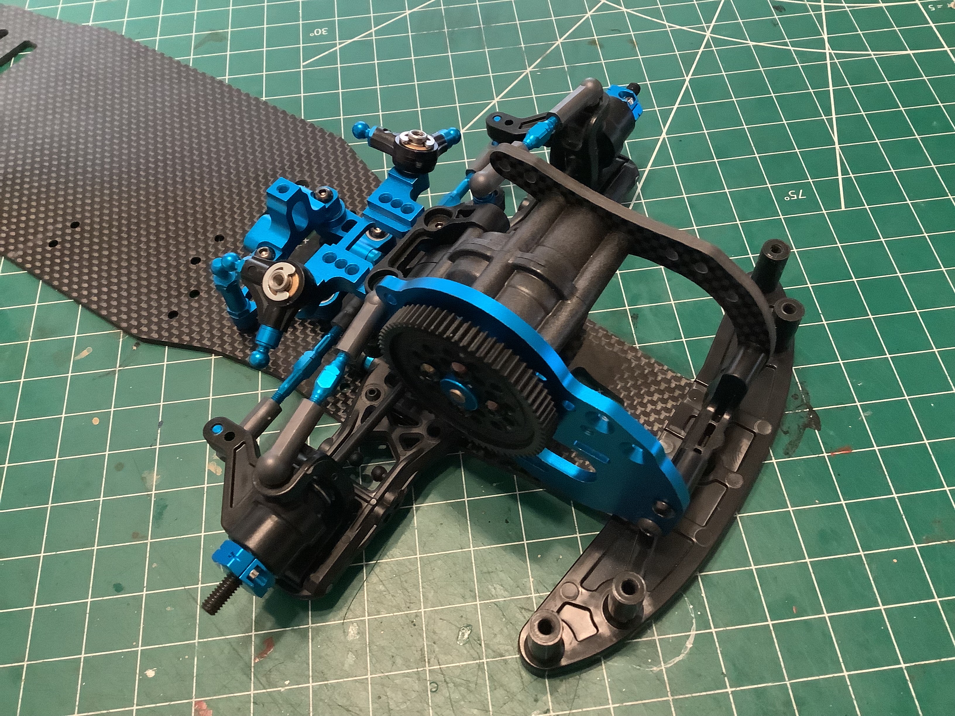
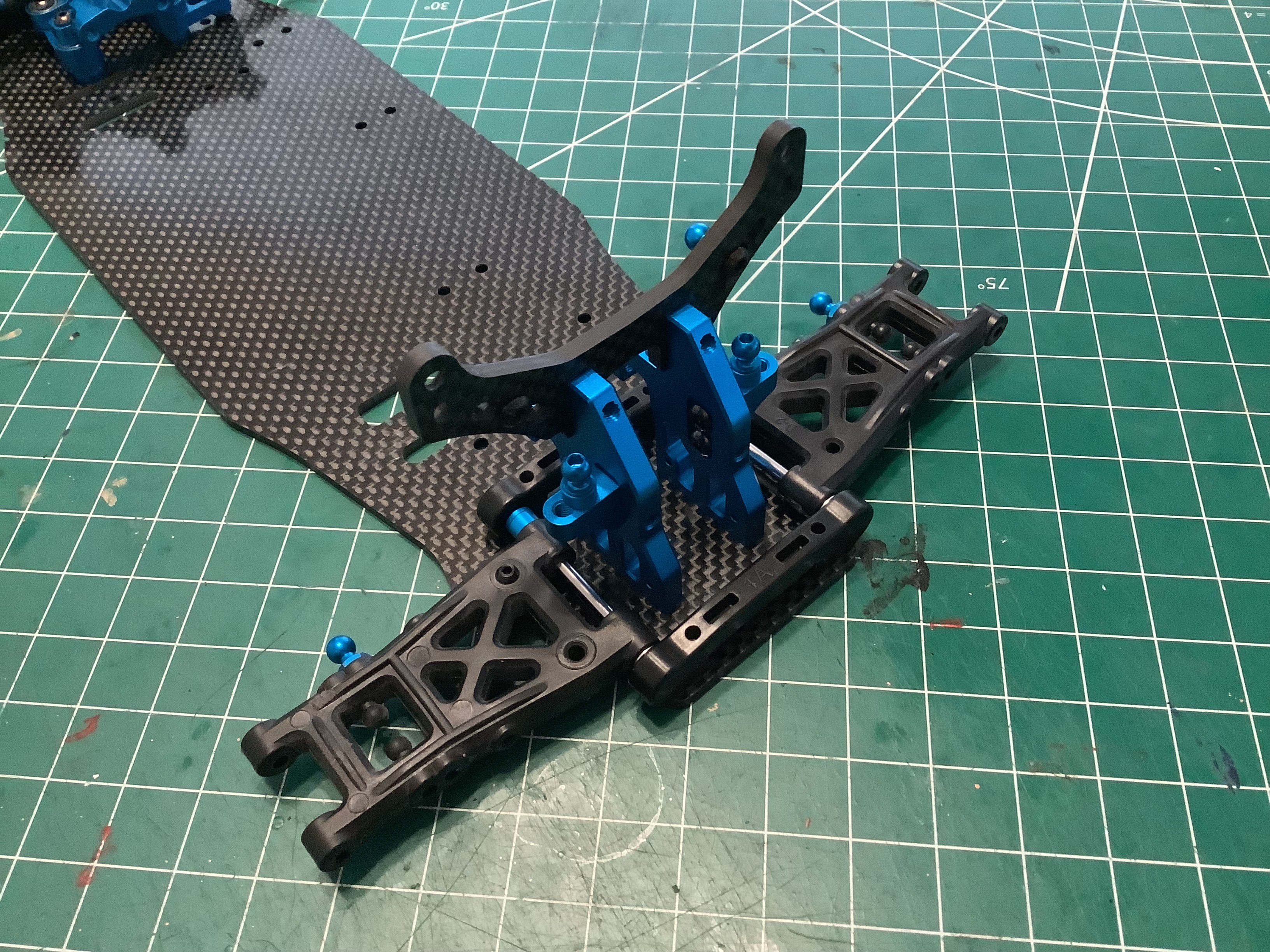
Adding the inboard front suspension mount assembly to the gearbox
assembly completes the front end module. It doesn't look like much
yet, but all of the suspension parts will connect to this.
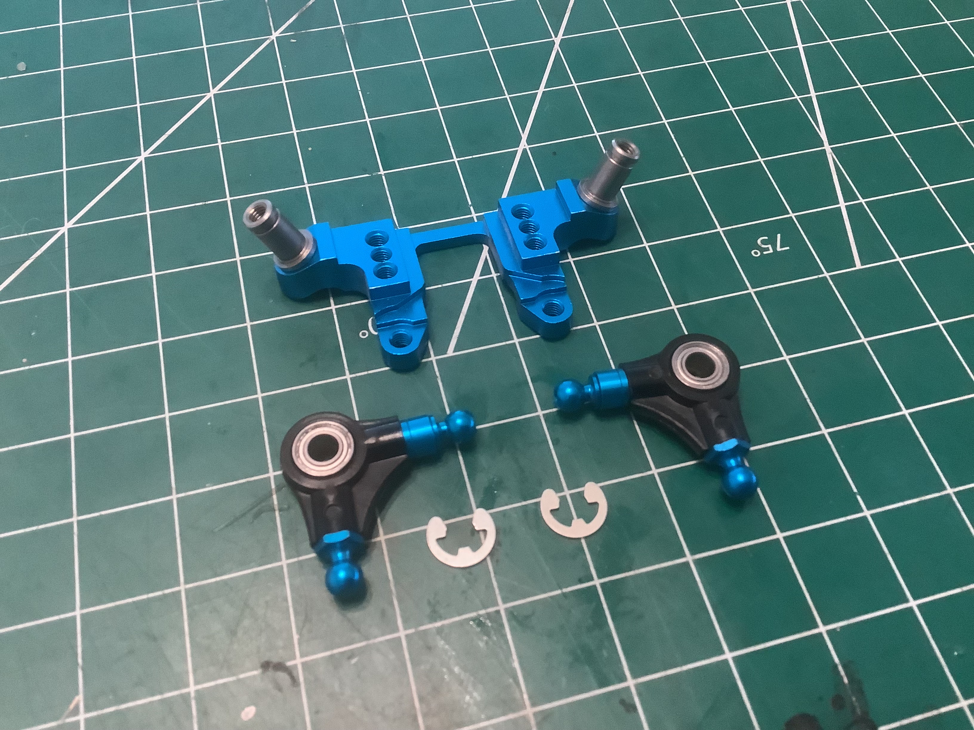
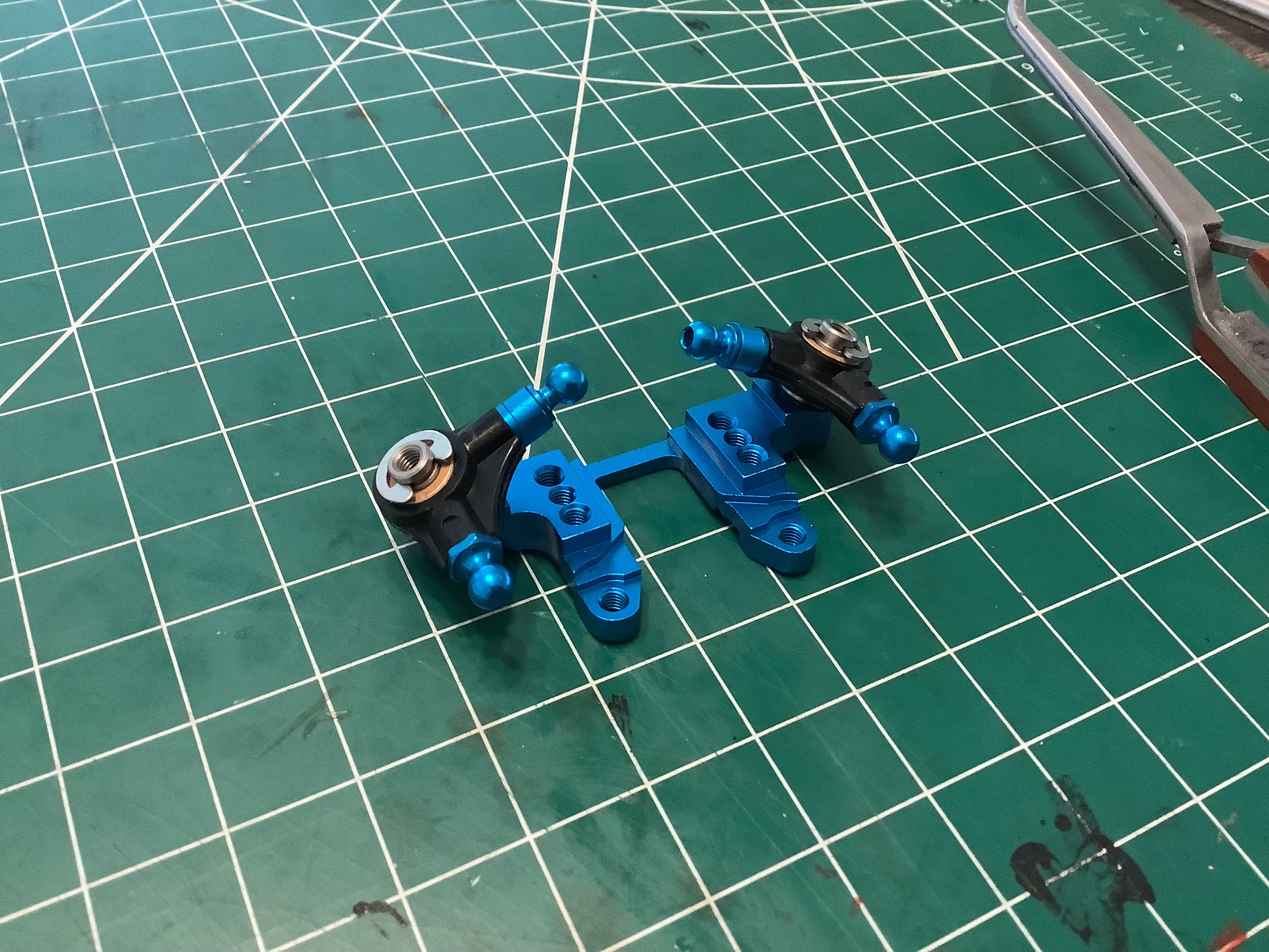
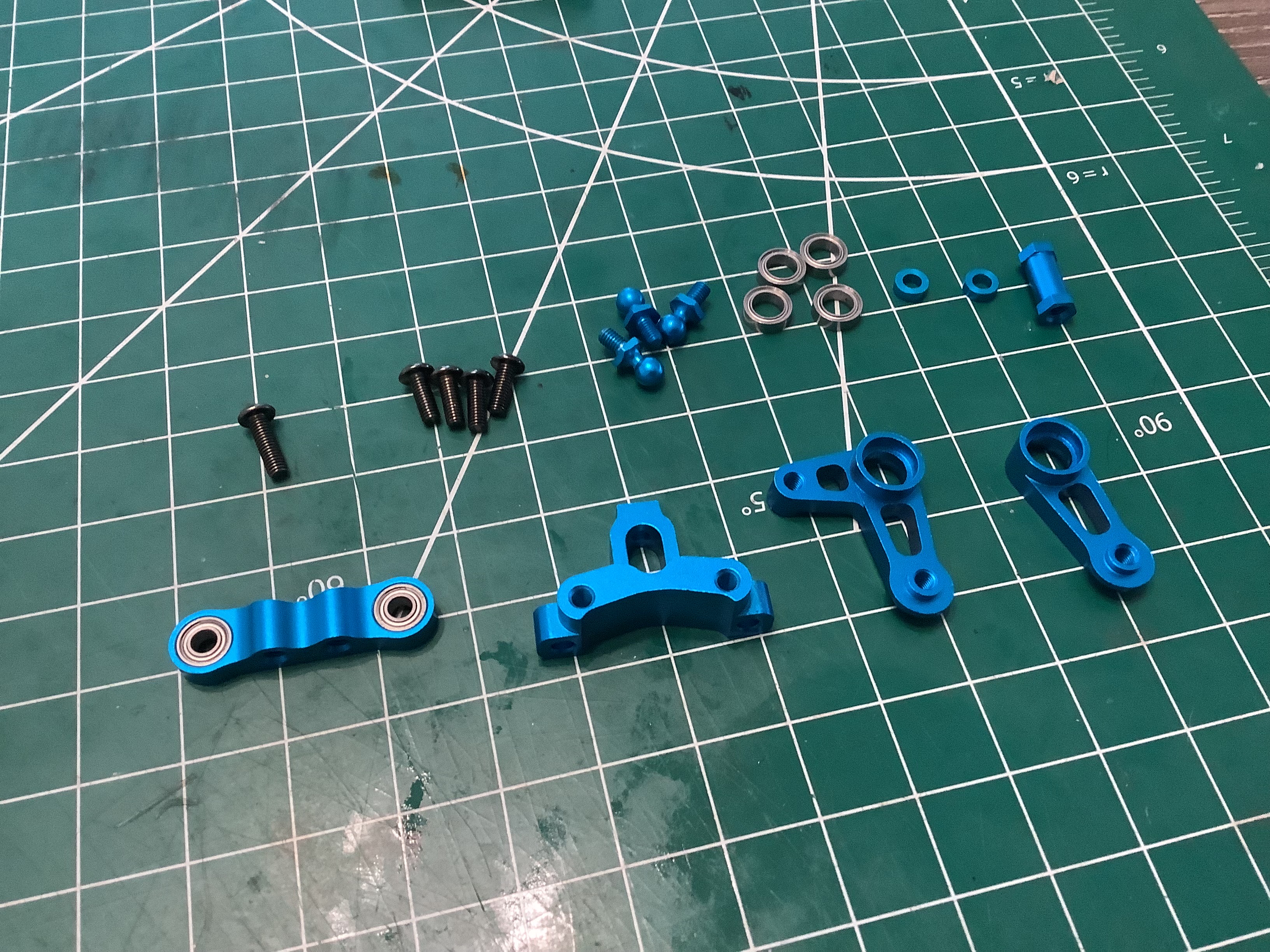
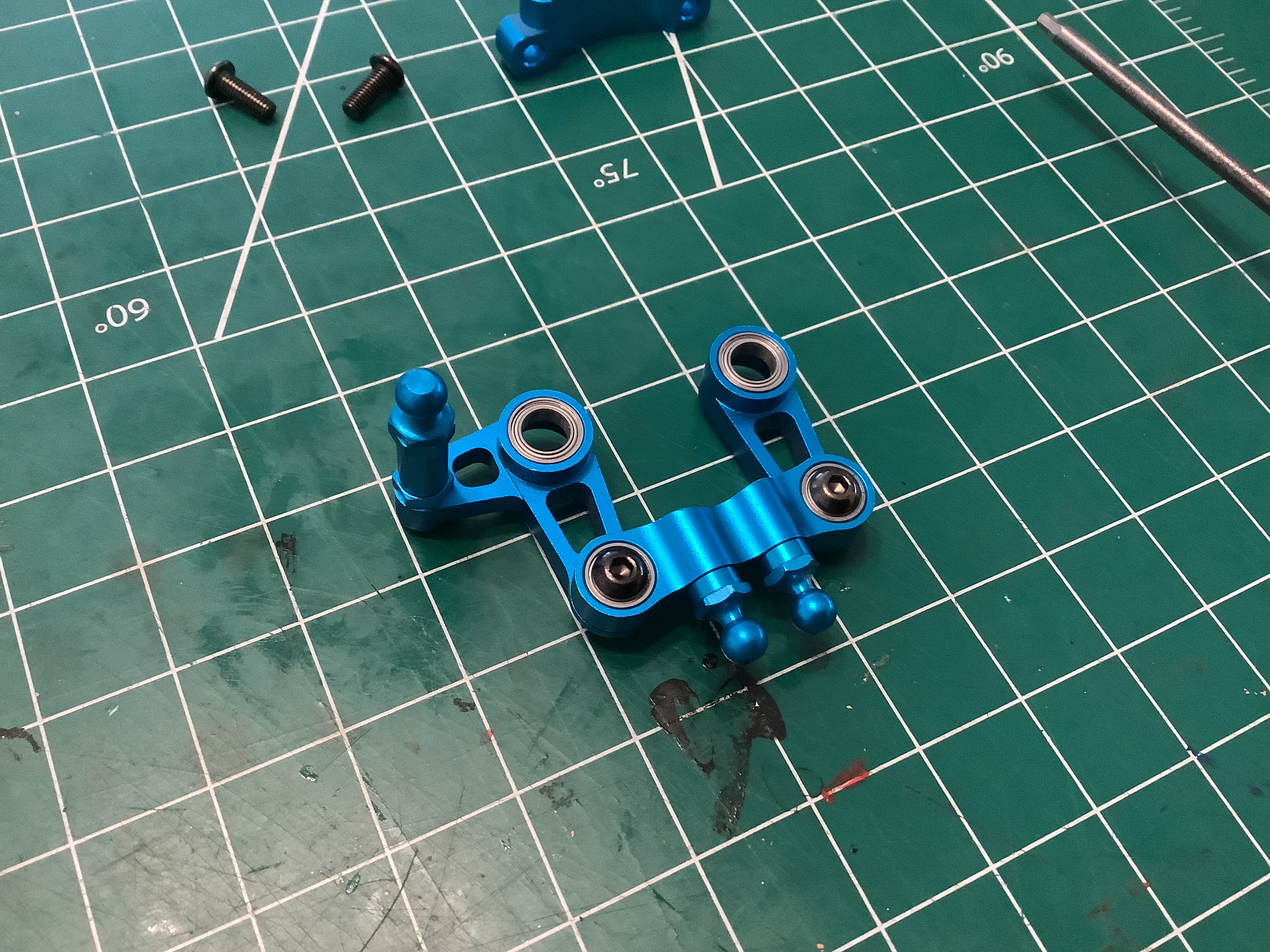
The next assembly to build is the steering system. The dual
bellcrank steering arms, steering bridge, and steering mount are all
machined aluminum right out of the box. Every joint uses ball
bearings and all the ball connectors are aluminum as well. It's
all very smooth to operate.
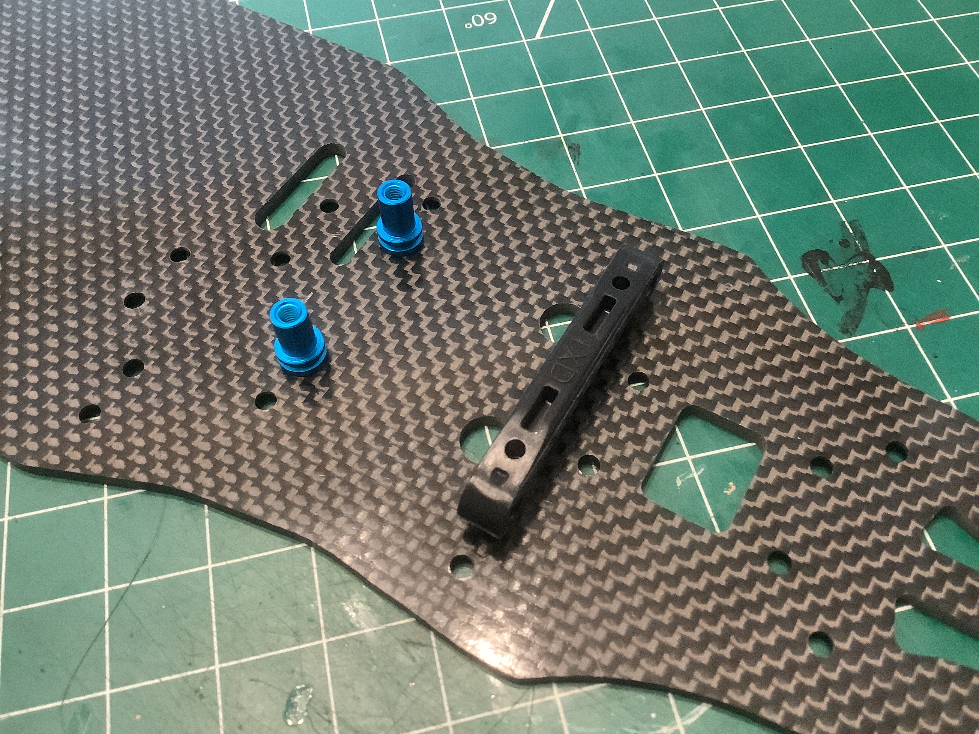
Now we can finally start on the chassis backbone. The primary
base plate is 2.5mm thick carbon fiber sheet. All of the holes on
the bottom surface are countersunk for a completely smooth underside
with no protrusions. First I've attached the aluminum steering
posts and the plastic lower suspension mount as shown on the left.
On the right I've added the steering crank assembly which comes very
close to the suspension mount.
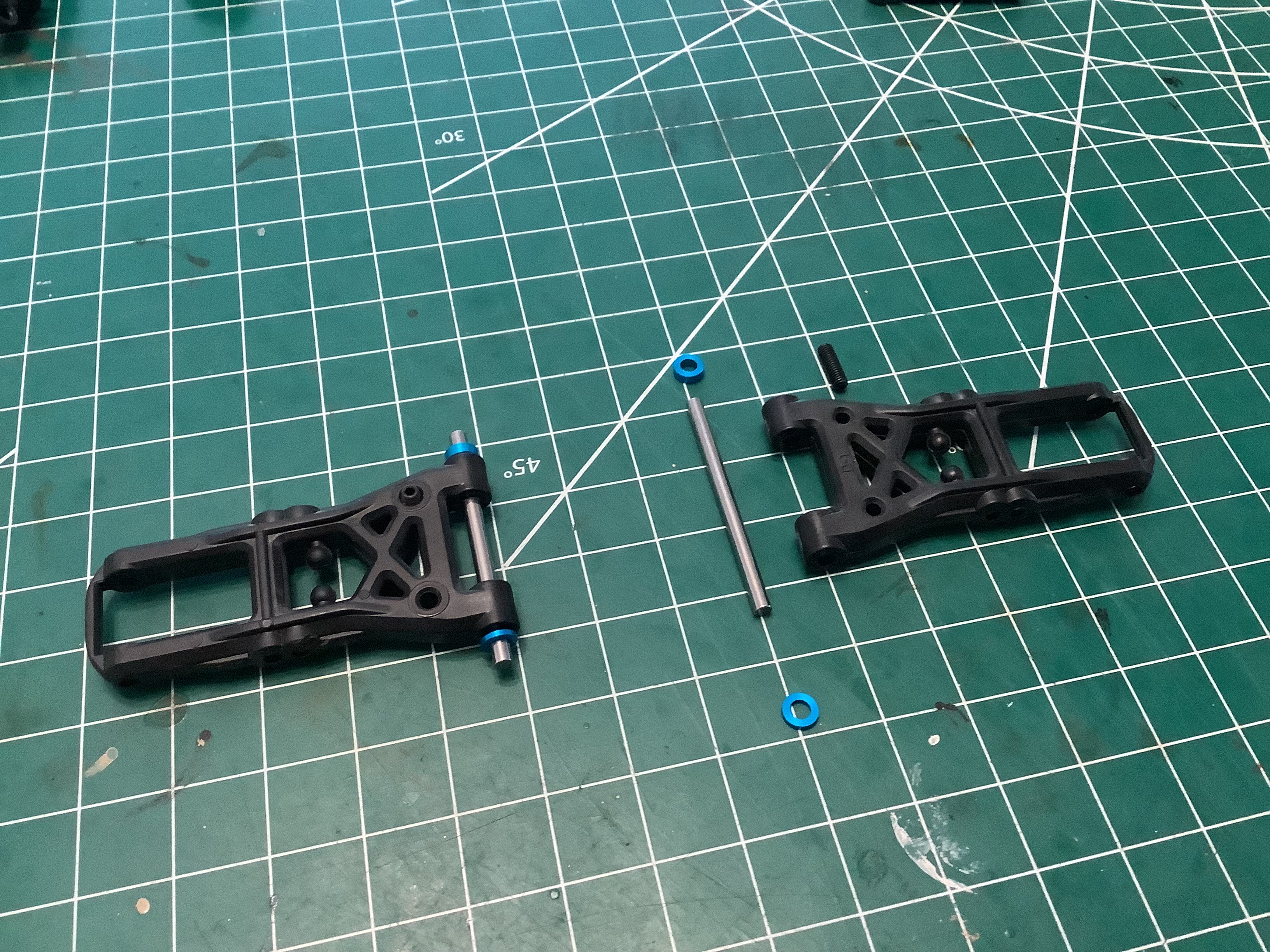
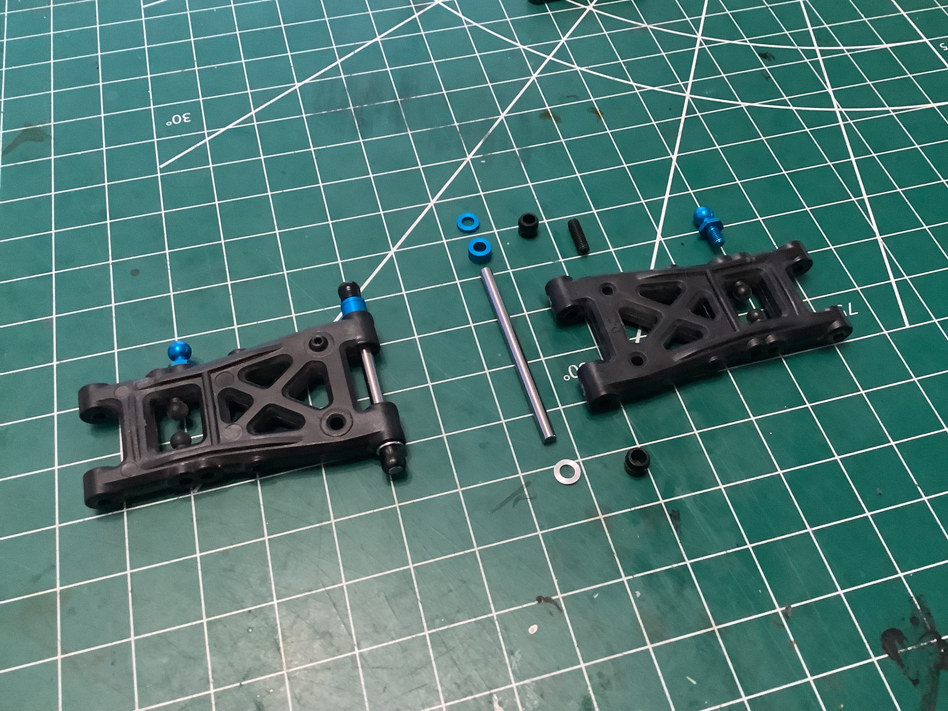
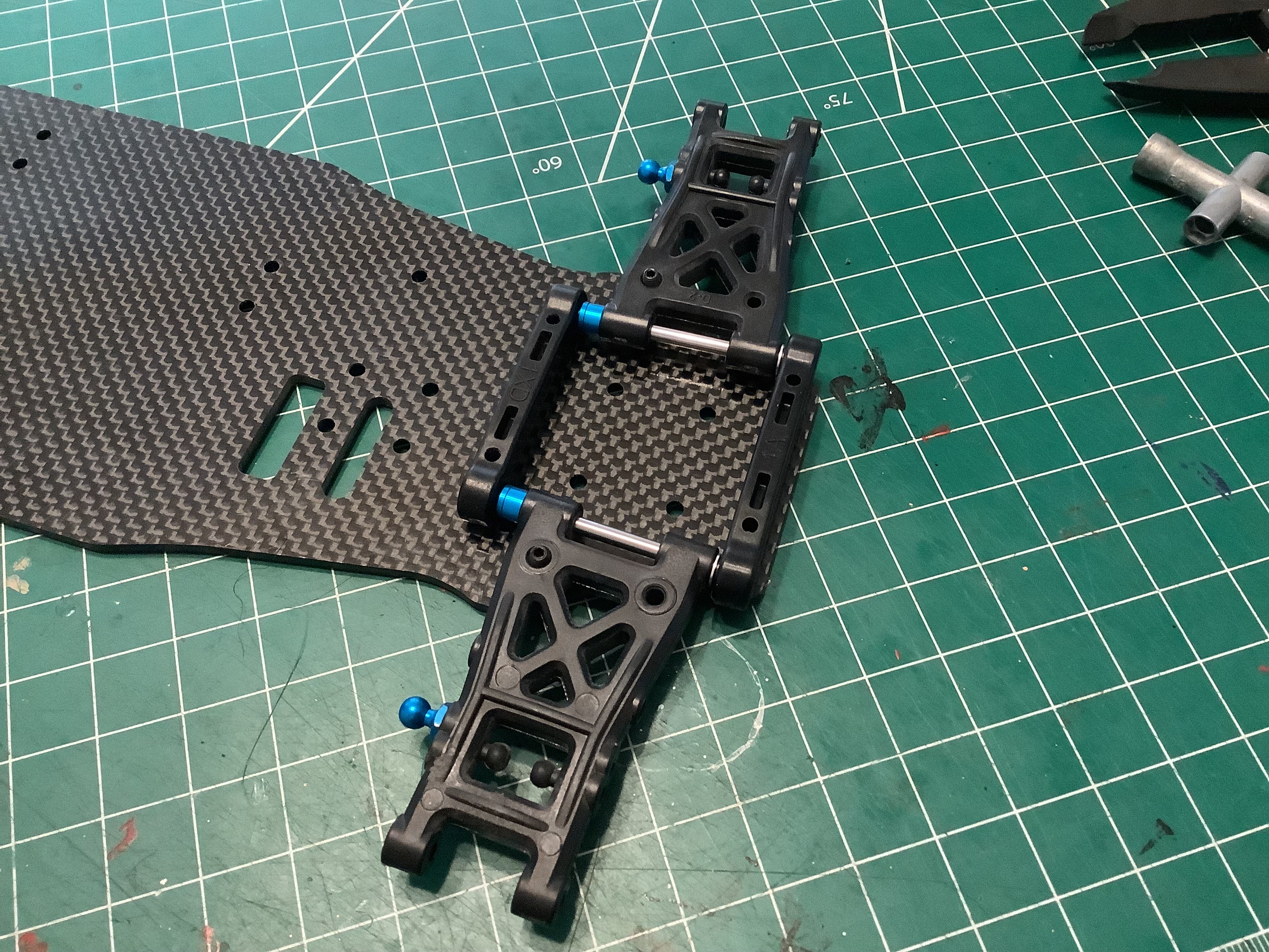
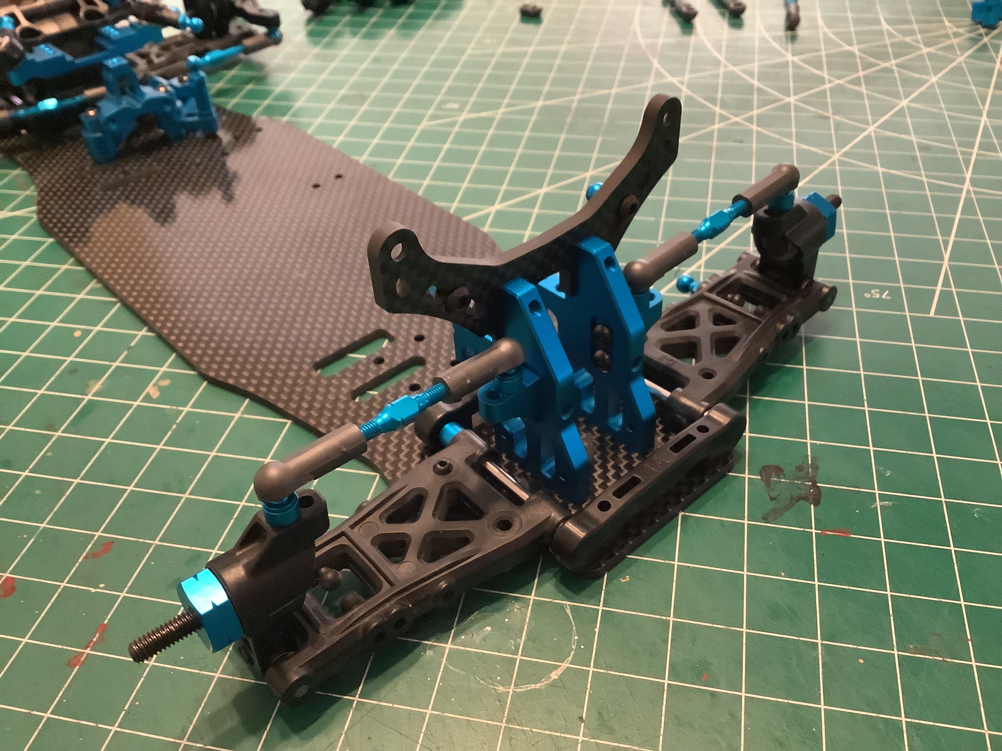
The lower reversible suspension arms can be flipped to make tiny changes
to the locations of the shock mounting holes so care must be taken to
be sure they are installed symmetrically. The spacers on either
side of the arm pivots can be changed to make small adjustments to the
wheelbase. Both suspension mounts are the same width (1XD) so
there is no toe angle built into the front arms. The steering
links use aluminum turnbuckles and have also been installed.
Now the gearbox has been installed on top of the lower suspension arms along with the plastic bumper support.
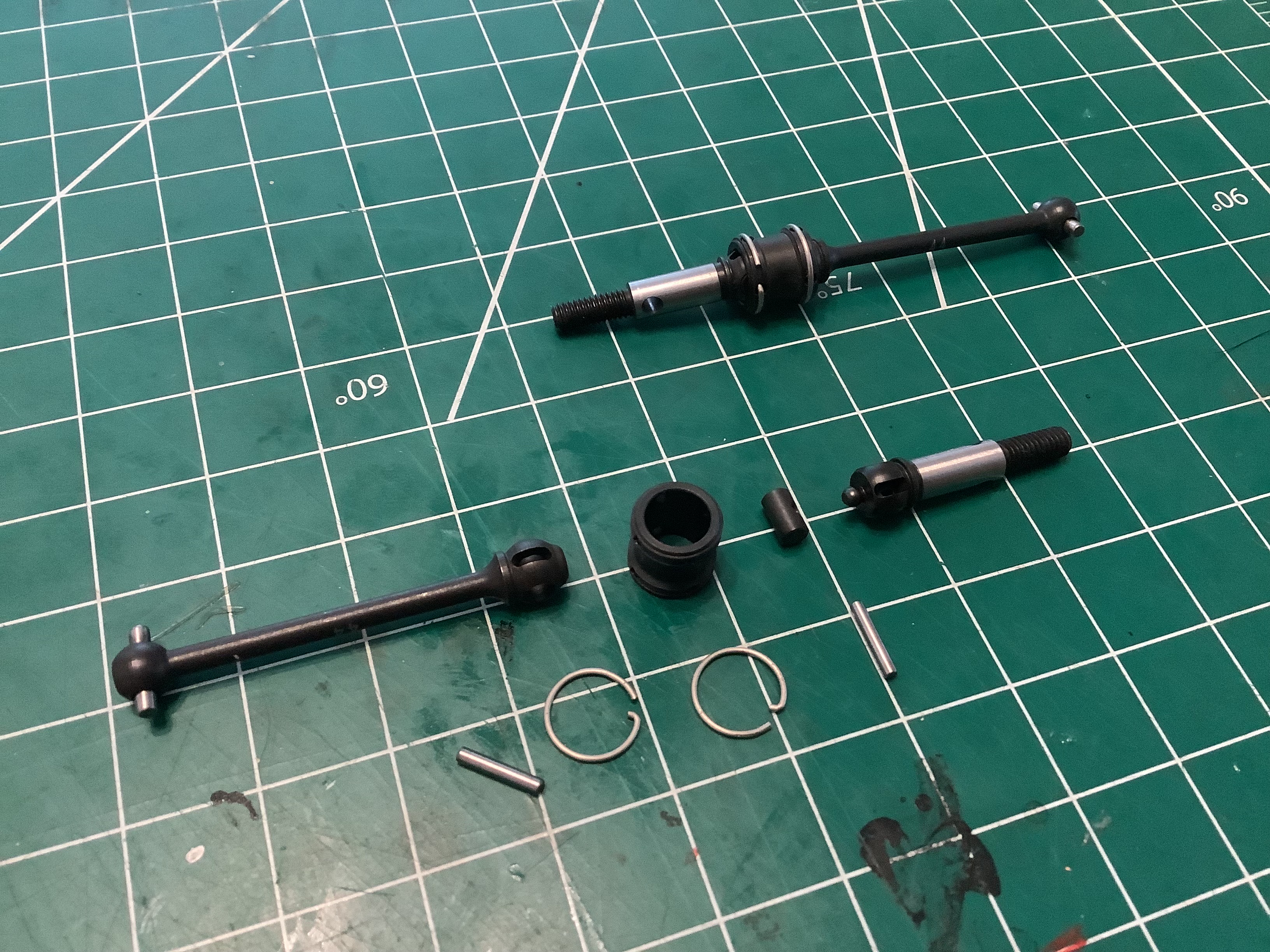
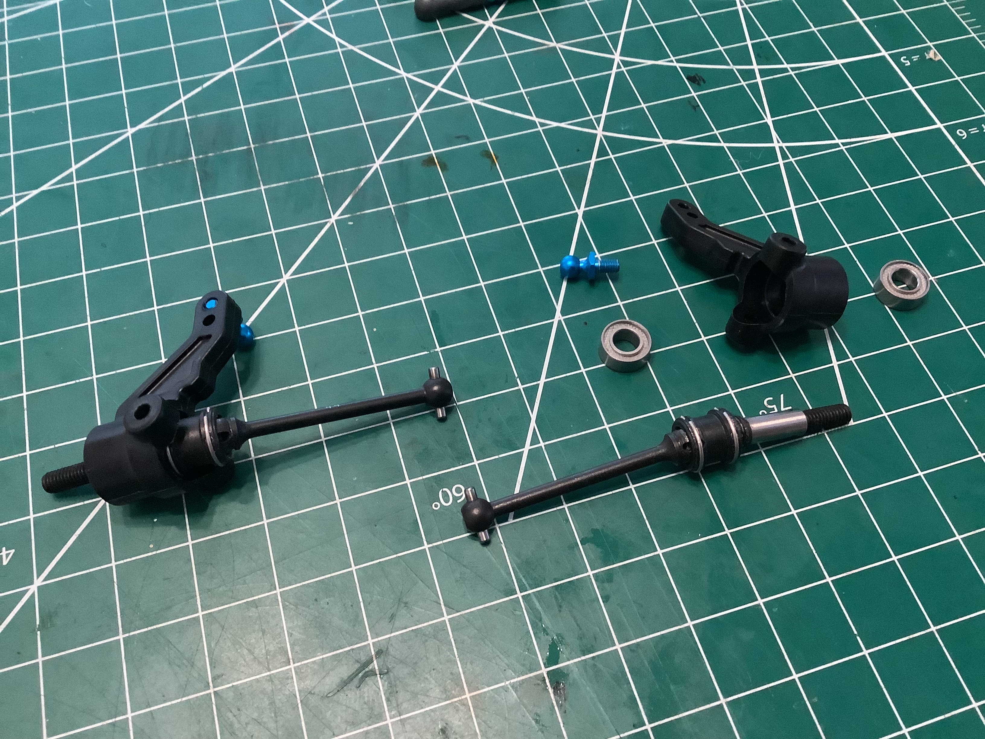
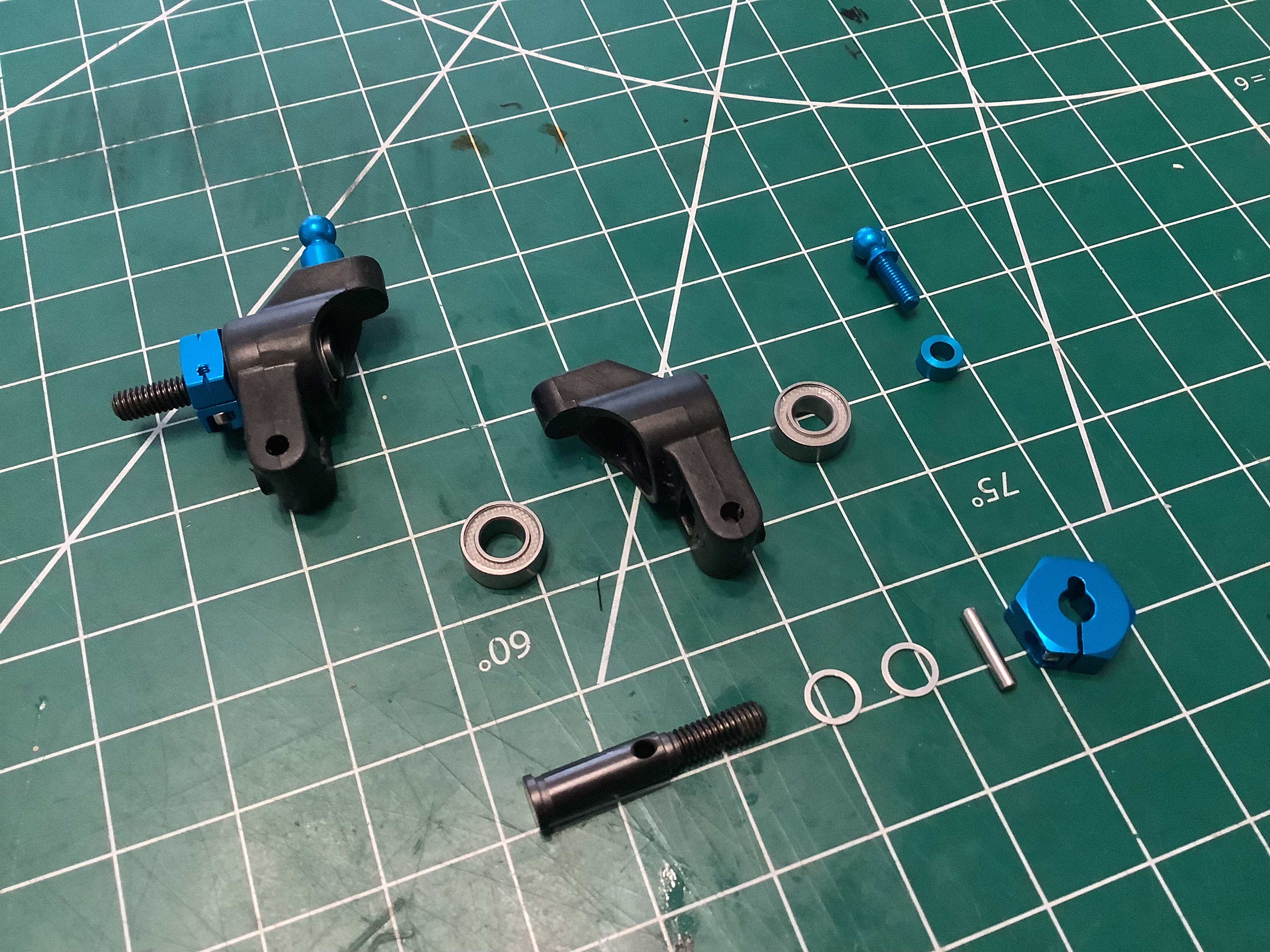
The EVO uses beautiful double cardan axles which have to be assembled
from seven separate parts as shown. These allow a much larger
steering lock with less chatter than a regular CVD. They are shown
installed into the steering knuckles on the right.
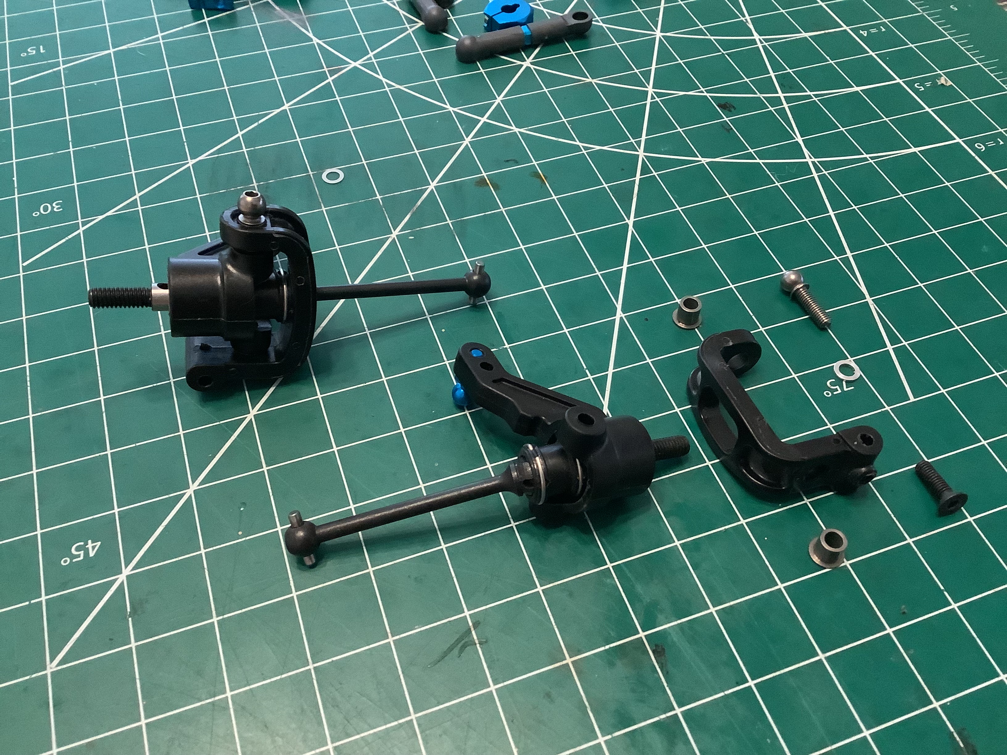
Each steering knuckle can now be installed into a C-hub using a pair of
flanged bushings to avoid clamping the joint. The completed front
suspension is shown on the right. The upper suspension links use
the same type of aluminum turnbuckles as the steering links.
Camber is altered by adjusting the suspension links and toe is altered
by adjusting the steering links. Note that the upper and lower
suspension arms have different lengths which results in the camber
increasing as a result of suspension compression.
The rear suspension goes together pretty much like the front using
reversible arms, pivot pins with ball ends, and spacers. In this
case the combination of a 1XD and 1A suspension mount results in a rear
toe angle of 2.5º.
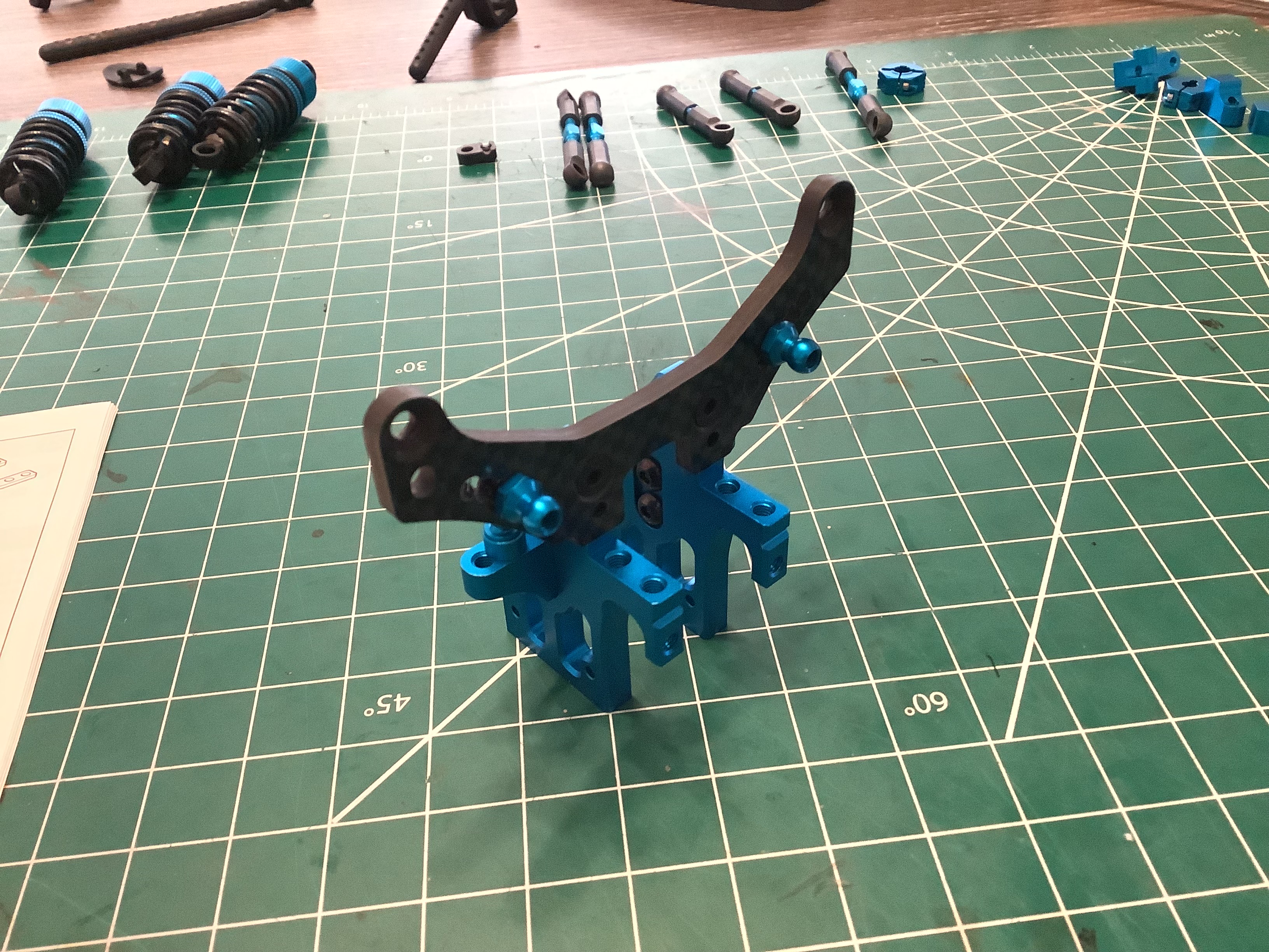
There is no rear gearbox or differential, so in this case the only
purpose of the rear bulkhead is to support the massive 3mm thick carbon
shock tower and upper suspension links. Even so we get these lovely
machined parts. Note how only the lowest holes in the shock tower
are used by default, so most of that width is unused in stock form.
Here the rear bulkhead has been attached to the chassis plate.
This looks very, very different from the plastic rear suspension
assembly of the standard FF-03. The rear shocks of the EVO will
now be installed on the front side of the suspension arms instead of the
rear side like the standard chassis.
The rear stub axles can now be installed into the uprights. The
shims shown limit the lateral play in the axles and keep everything
tight. On the right you can see the completed rear suspension
using aluminum turnbuckle upper links. Also note the clamping
aluminum hexes.
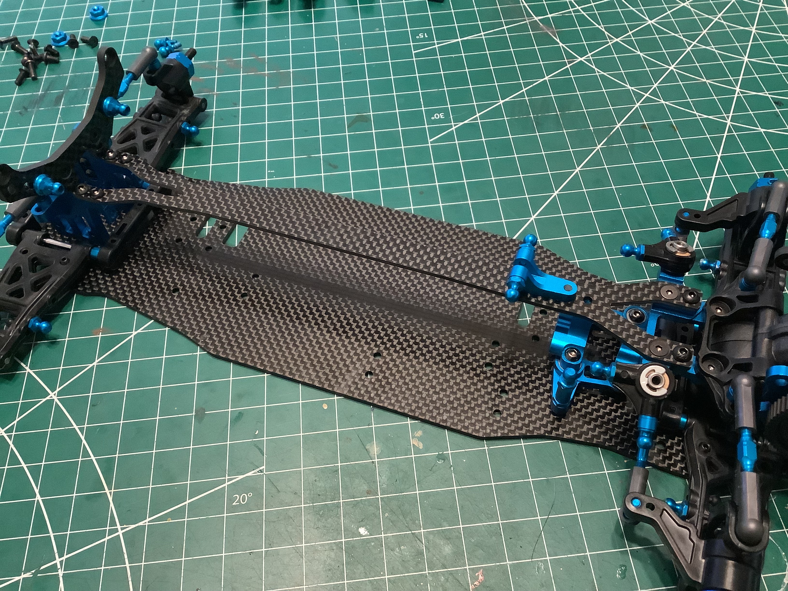
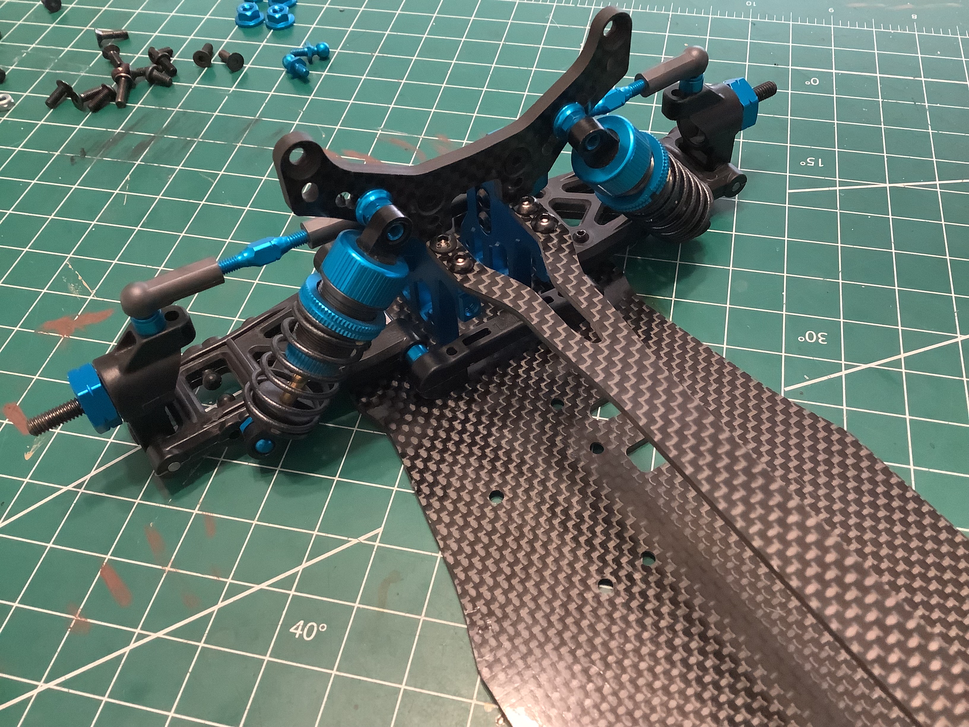
If the entire stiffness of the chassis were based on a 2.5mm carbon base
plate with nothing between the front and rear bulkheads, it would be
very flexible indeed. To counter this, a 2mm thick upper chassis
plate is added to span the tops of the bulkheads. This completely
alters the overall stiffness. This upper plate also serves as the
support for the central aluminum shock mount shown.
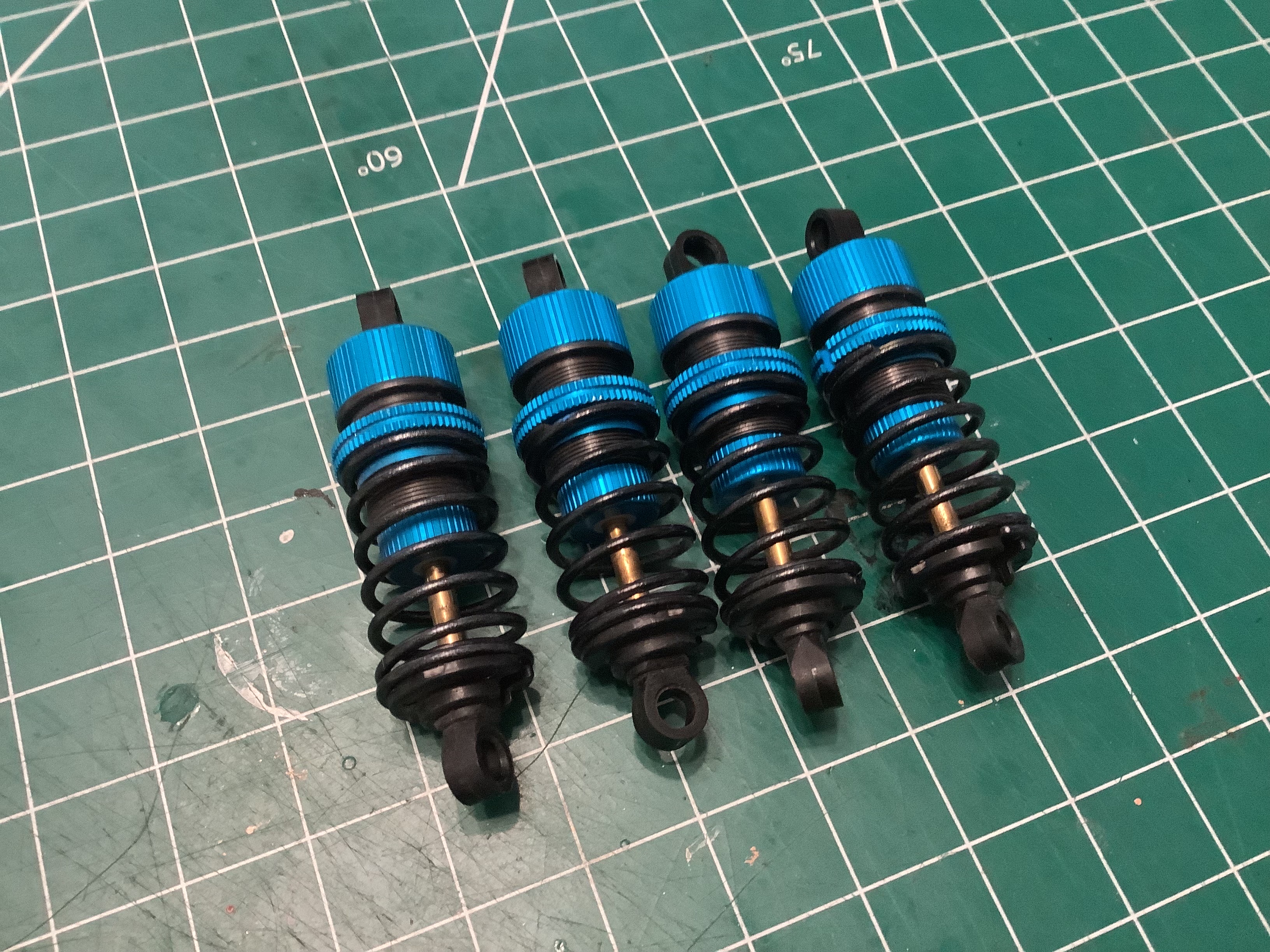
Here are the beautiful TRF shocks that I've come to know and love.
They are always a pleasure to build and operate as smooth as
silk. These springs appear as black in photos from the Tamiya
Japan web site but white in the North American site. They are
otherwise identical to the shocks that come with the FF-03 PRO and R.
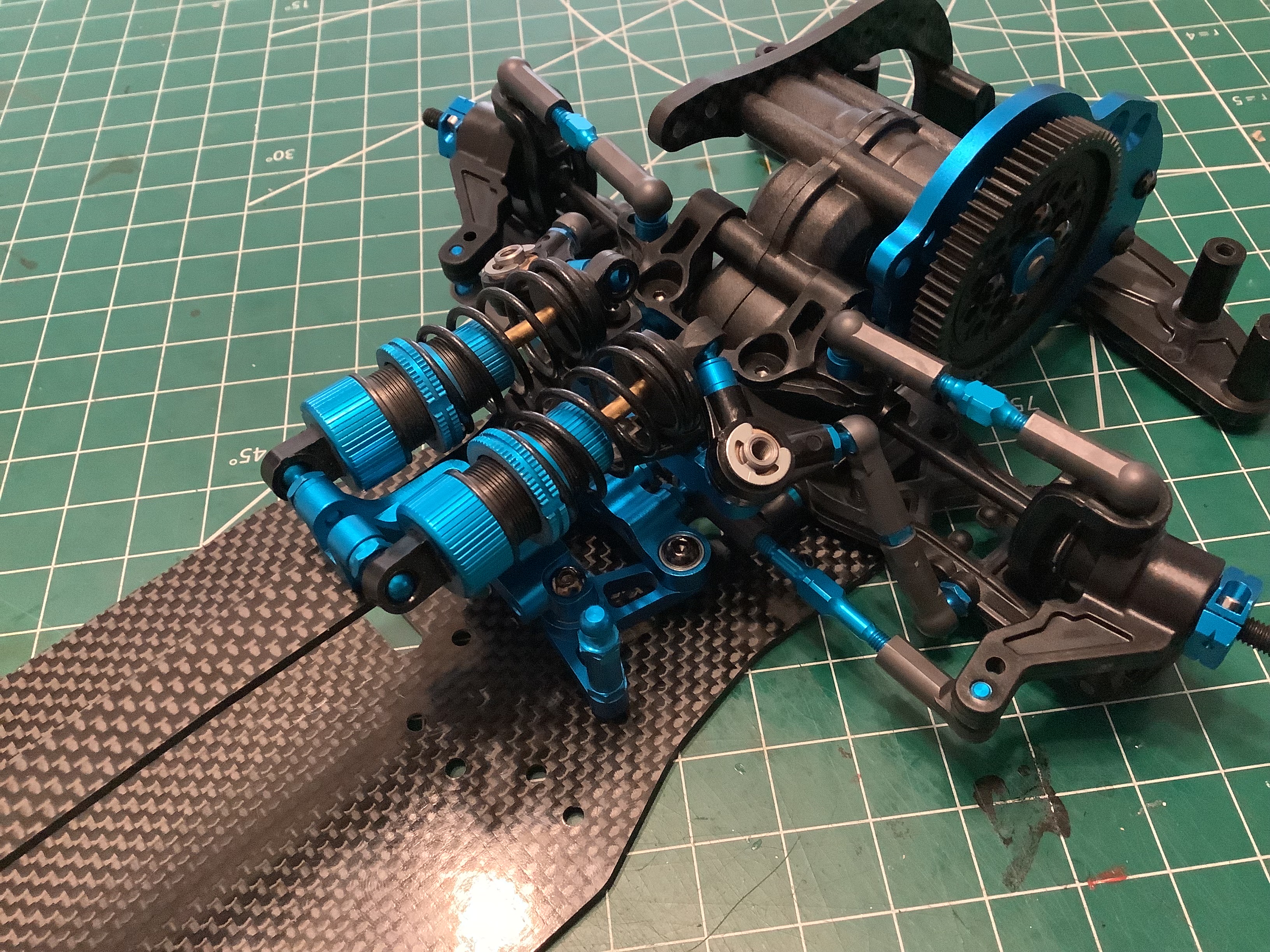
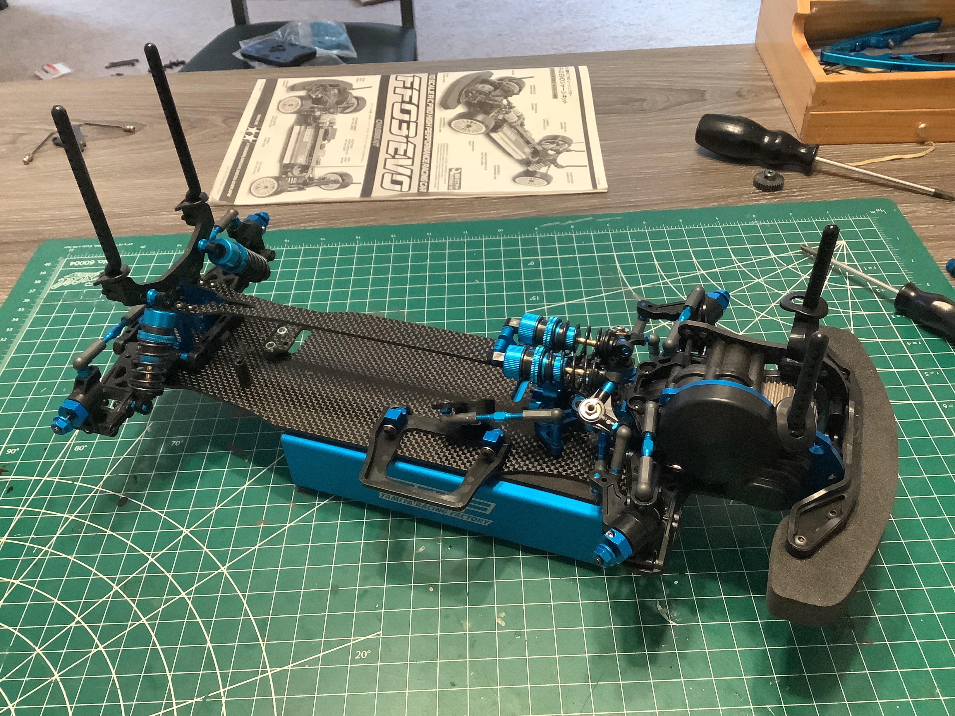
Installing the shocks in the front and rear completes the assembly of
the suspension. The rear shocks are mounted in a traditional
"vertical" manner, but are still angled quite significantly by
default. Other holes are available in the shock tower to make them
slightly more vertical. The front shocks are mounted in a
longitudinal orientation which differs from the lateral orientation of
the standard chassis. I'm not sure what the advantage of this
configuration is.
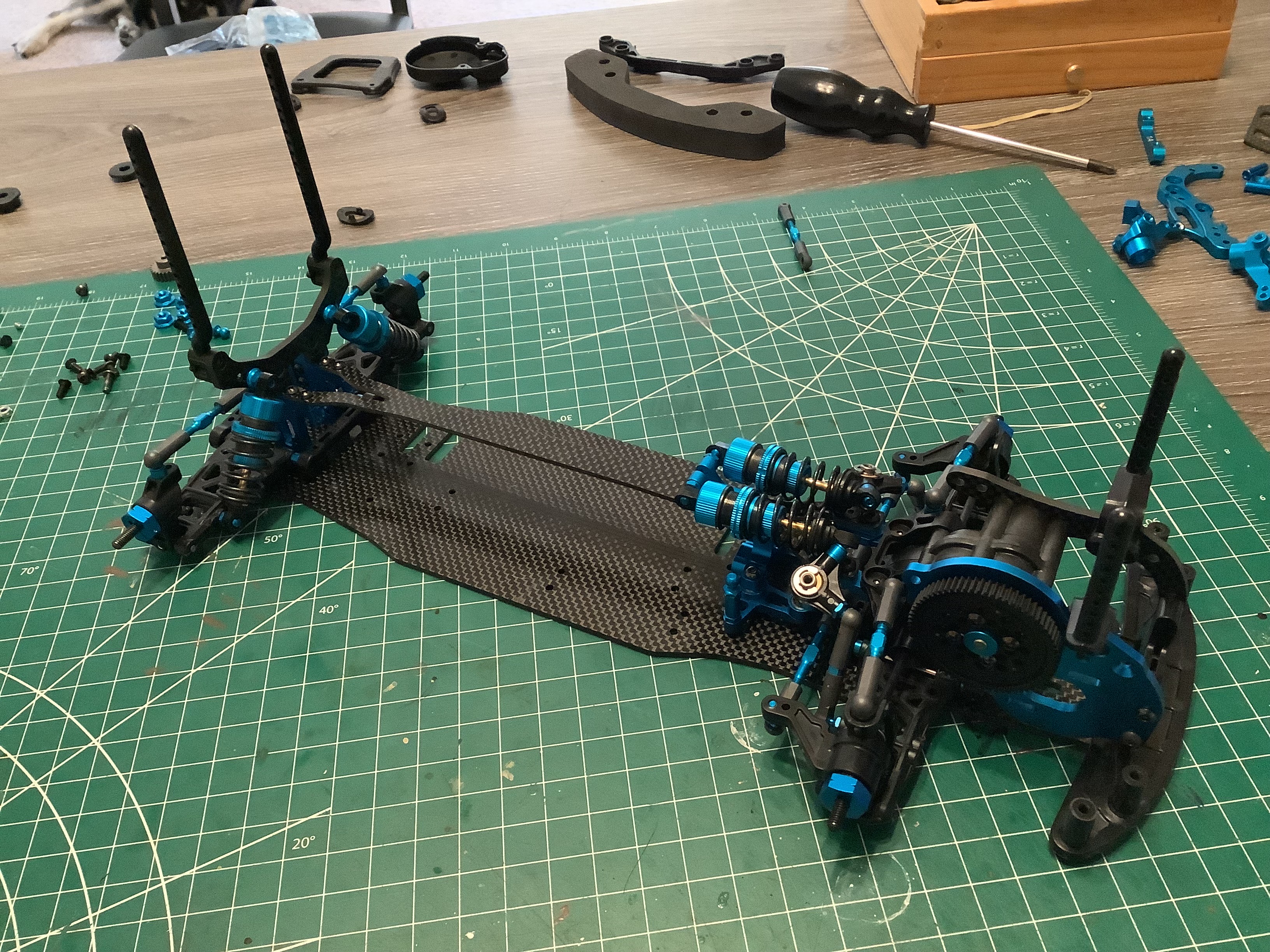
The body posts are very tall! I can't imagine any touring car body
that would require such a length, but it is nice to have the option.
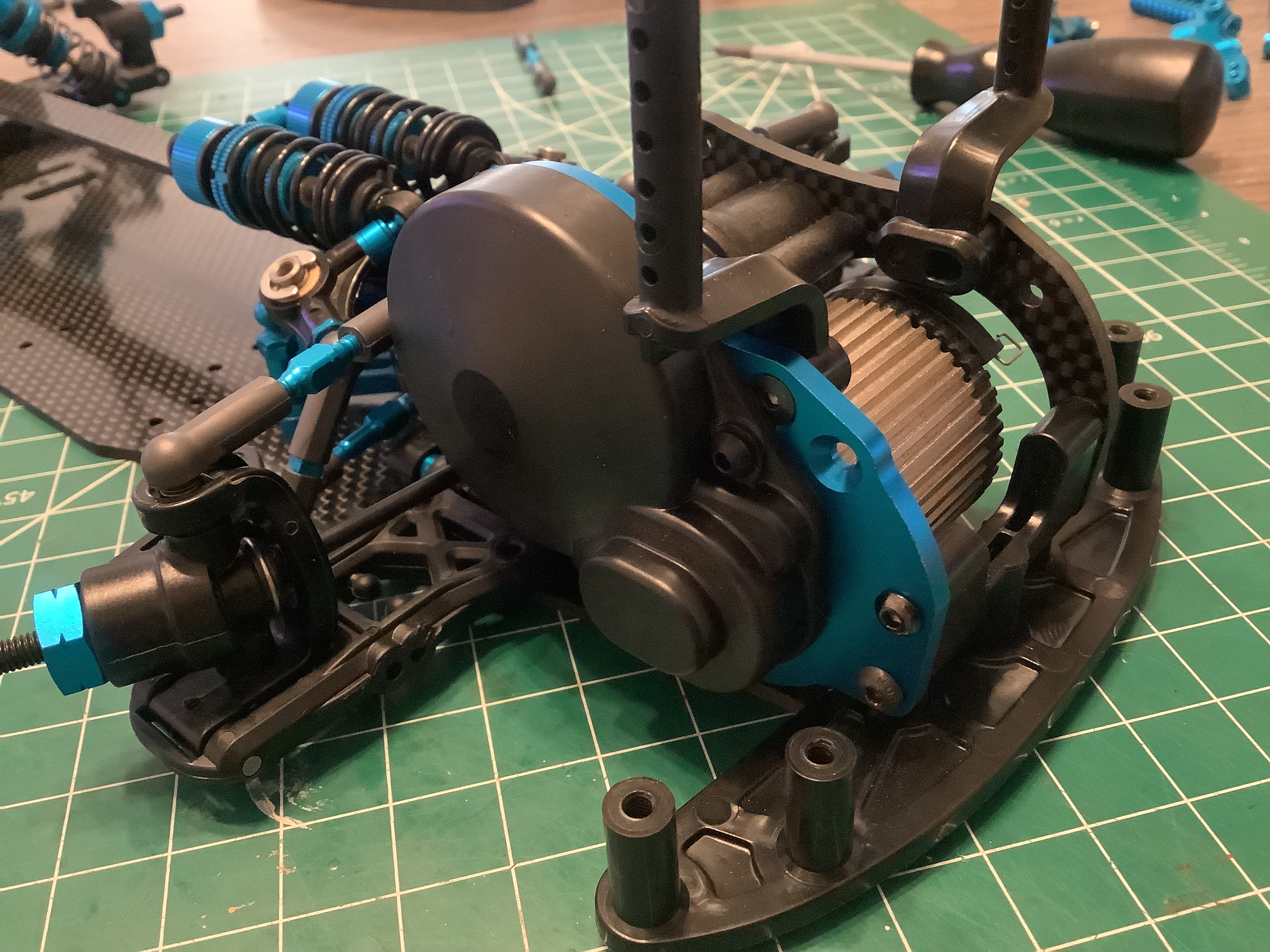
Here I've installed a temporary motor and a 26T 0.6 mod steel pinion
gear. A plastic cover is the installed over the pinion and spur to keep
out dust and rocks.
The final details are the servo tray and high torque (but not aluminum)
servo saver. I'll install the rest of the electronics after I
install a bunch of upgrade parts.
©2023 Eric Albrecht