Tamiya Frog Project
Page 1: Assembly
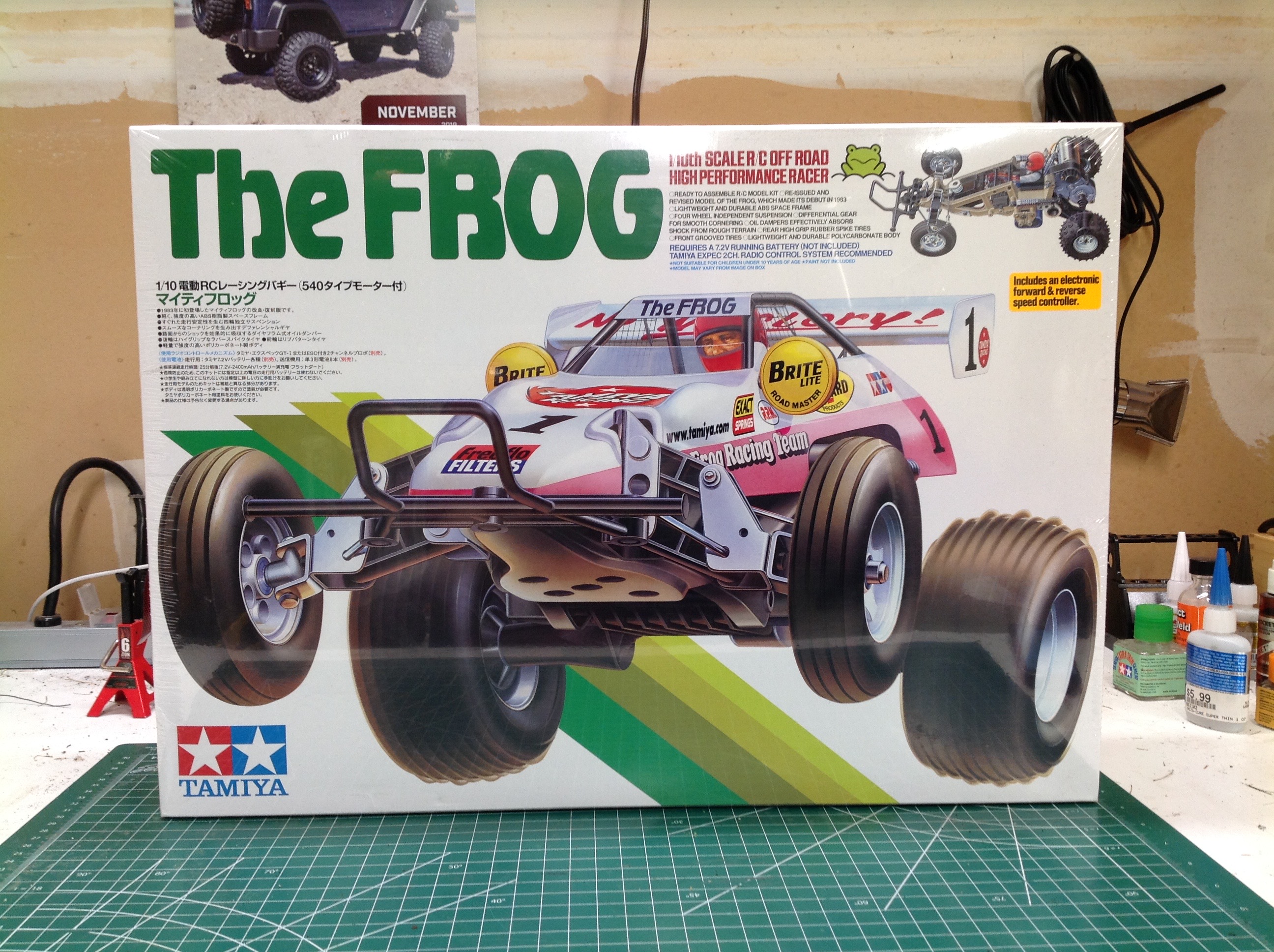
The Frog comes in this lovely box with classic box art. The
picture is almost the same as the original but the content of the
stickers has been modified to remove the unlicensed company names.
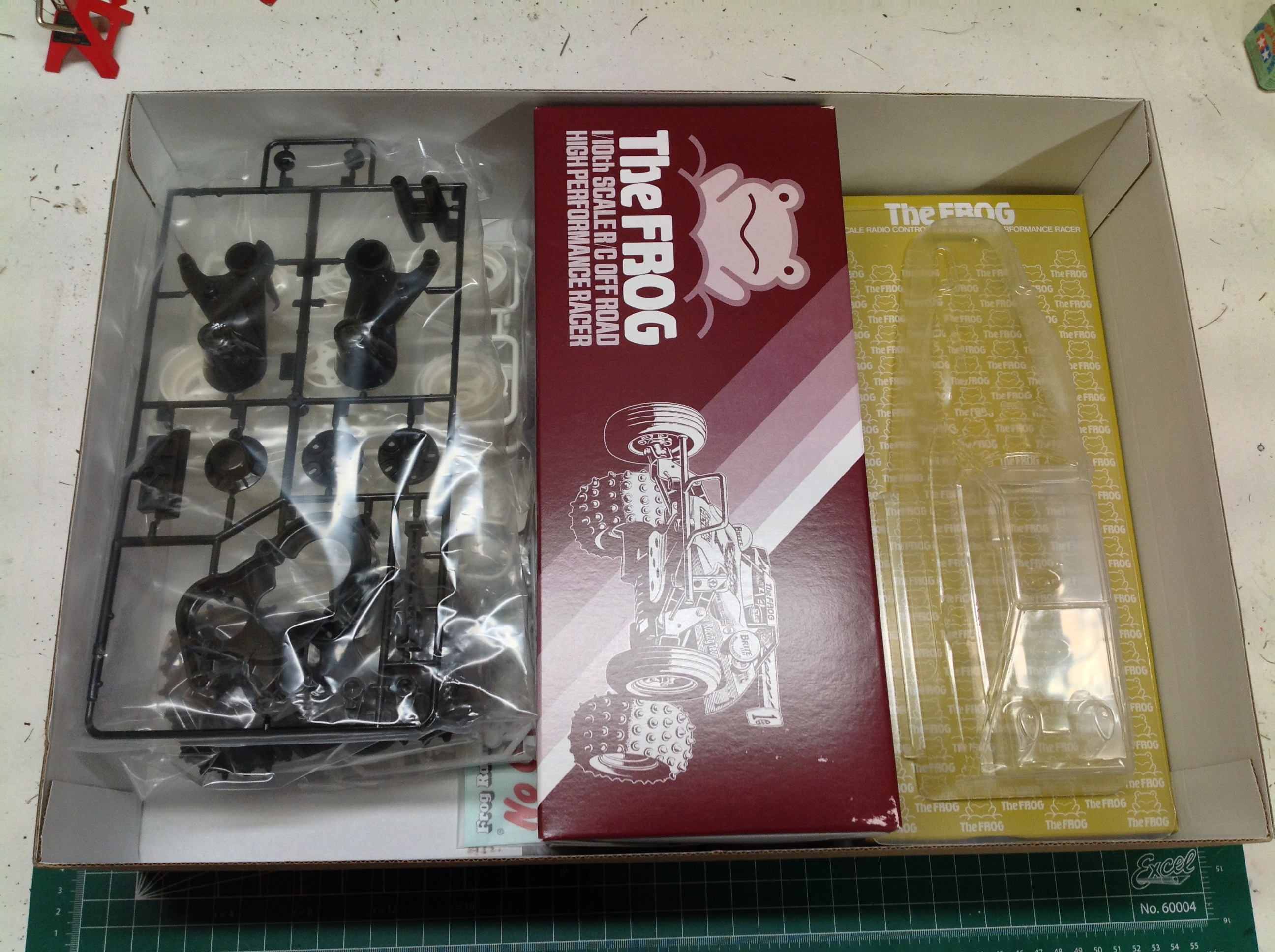
The picture on the right shows the arrangement of parts in the
box. There are no blister packs, but everything is still nicely
organized.
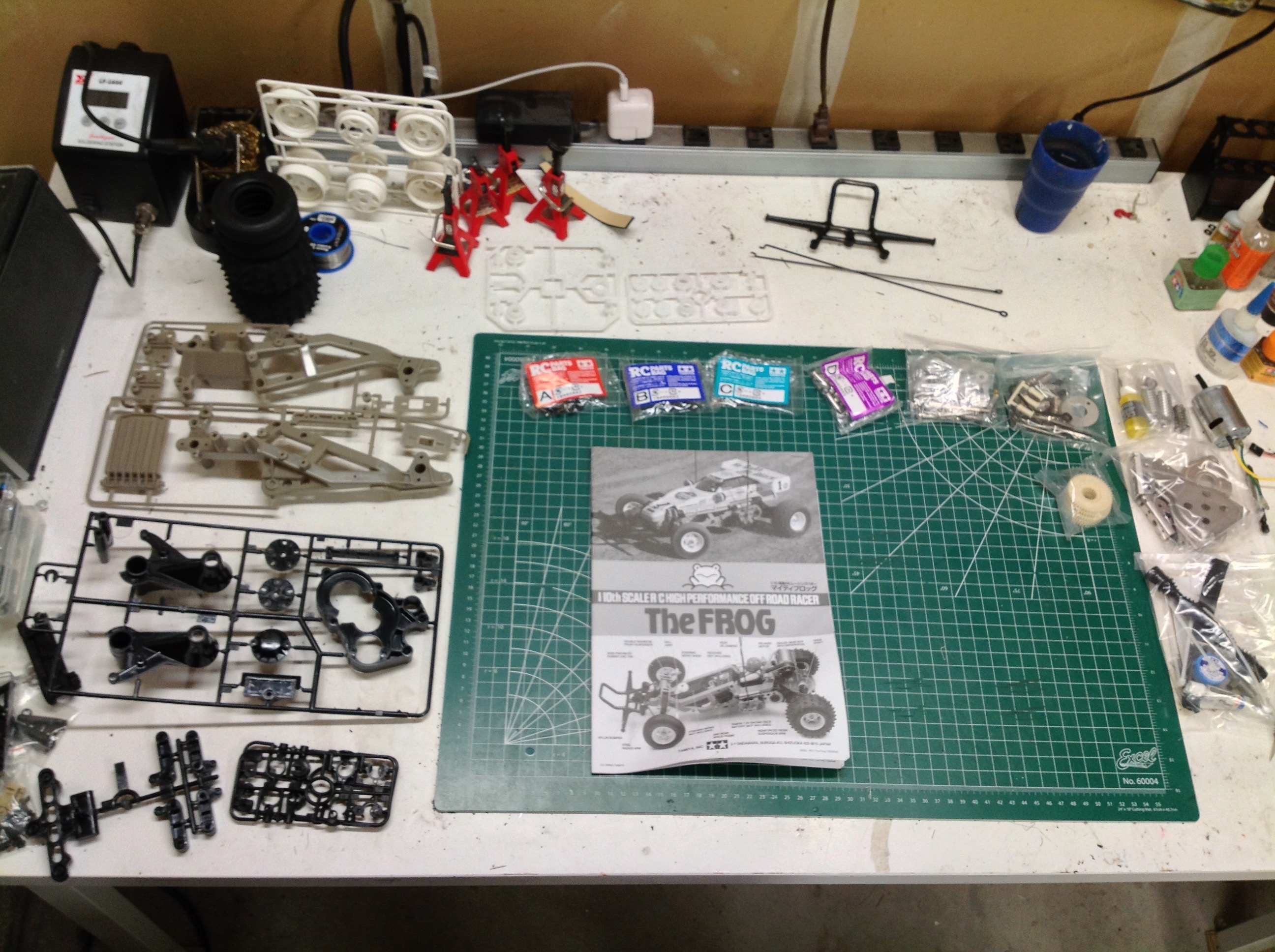
There are not very many plastic parts in this model as evidenced by the
handful of plastic trees shown to the left of my cutting mat. The
rest of the parts are metal and are either bagged separately or with the
hardware.
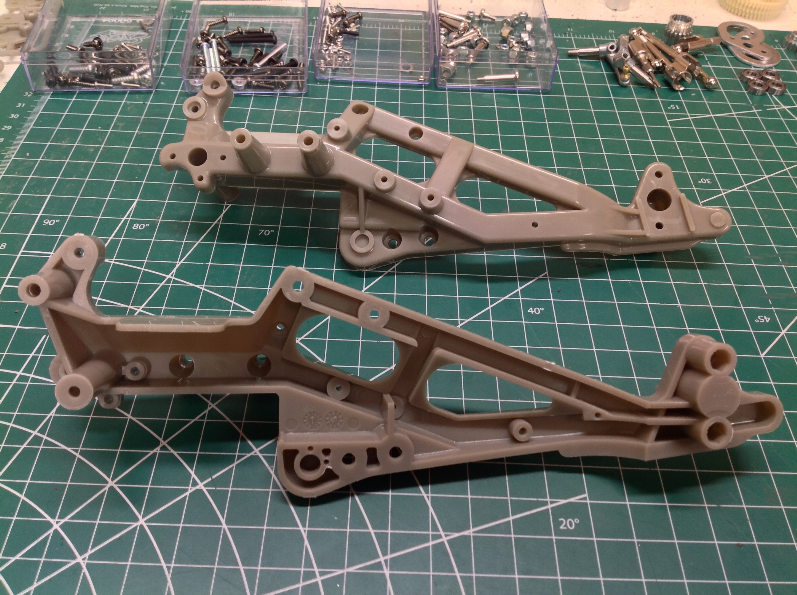
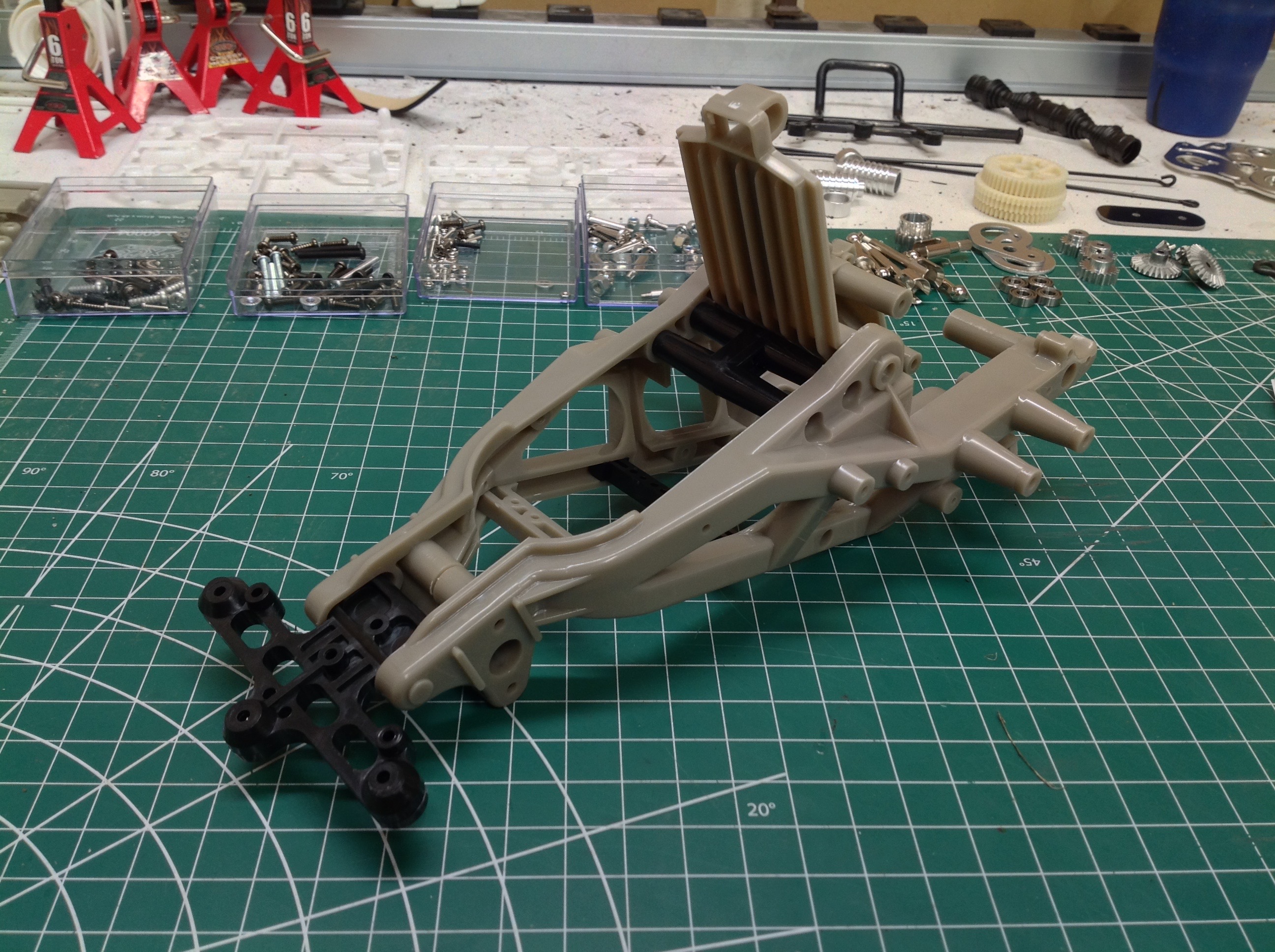
The ORV chassis is often described as a "space frame" design.
Rather than being an enclosed tub, the chassis uses an open
framework. It is not a ladder frame like a truck because the rails
are much more three dimensional with upper and lower rails canted
downward toward the front. The chassis rails are ABS which, in my
opinion, is too brittle for the primary structure of a buggy. Care
must be taken not to over tighten fasteners or it will crack rather
than strip. The gray frame comes in left and right halves as
shown. They are then attached together with some cross members
between as well as the battery hatch and front bulkhead which will
support the suspension. After completing this single step, the
chassis has already mostly assumed its final shape.
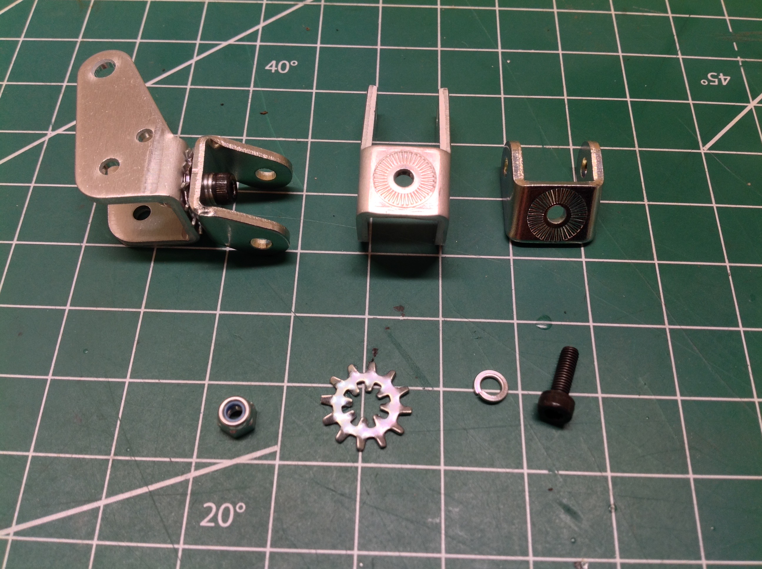
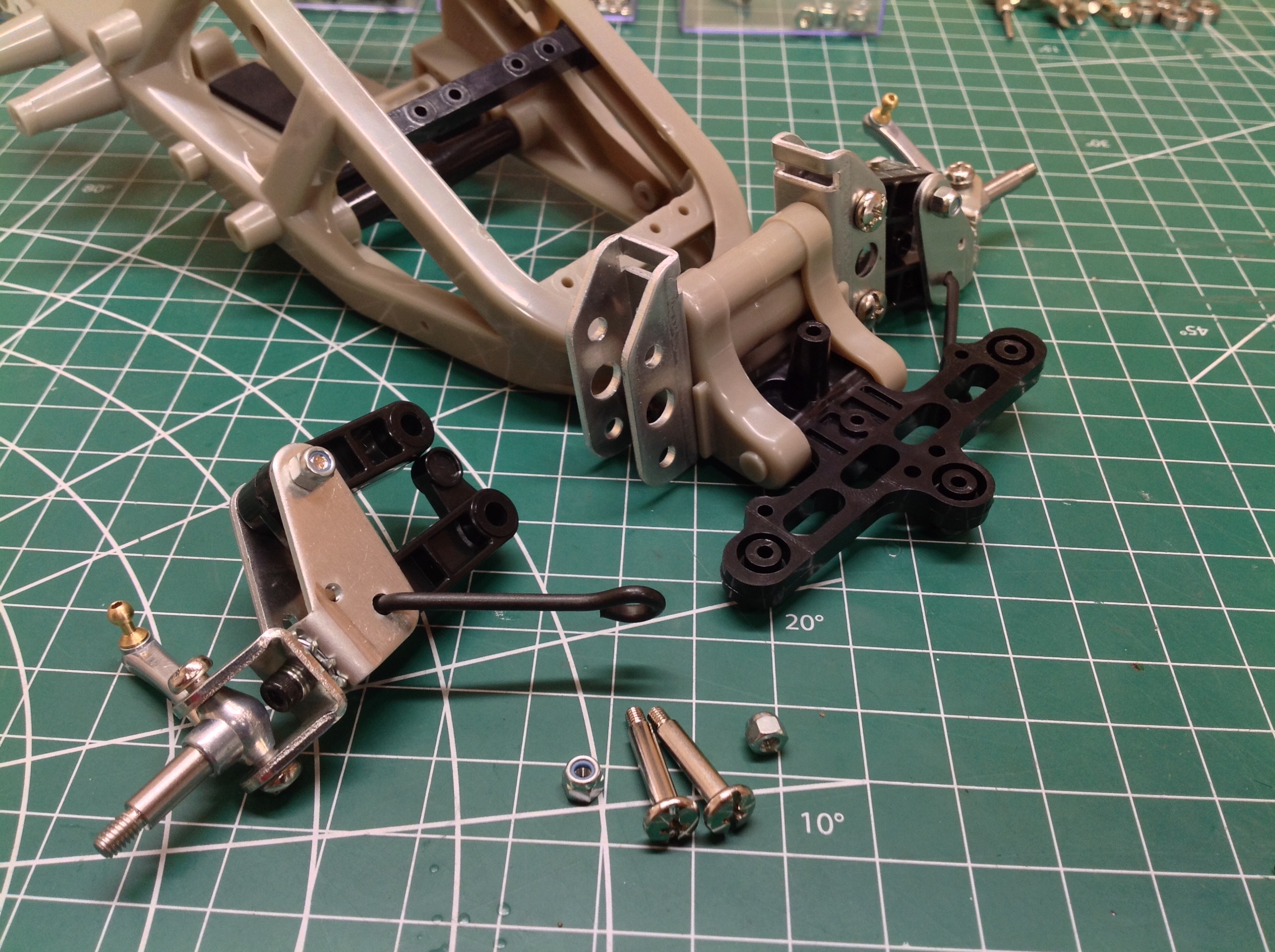
The front suspension is fascinating. Both the upright and the
C-hub are bent sheet metal. Since the C-hub attaches with only a
single screw, it is subject to rotation which would change the caster
angle. To prevent this, Tamiya includes the star washer shown
which is supposed to lock them together. It seems to work pretty
well. Note that the area around the holes on the mating parts is
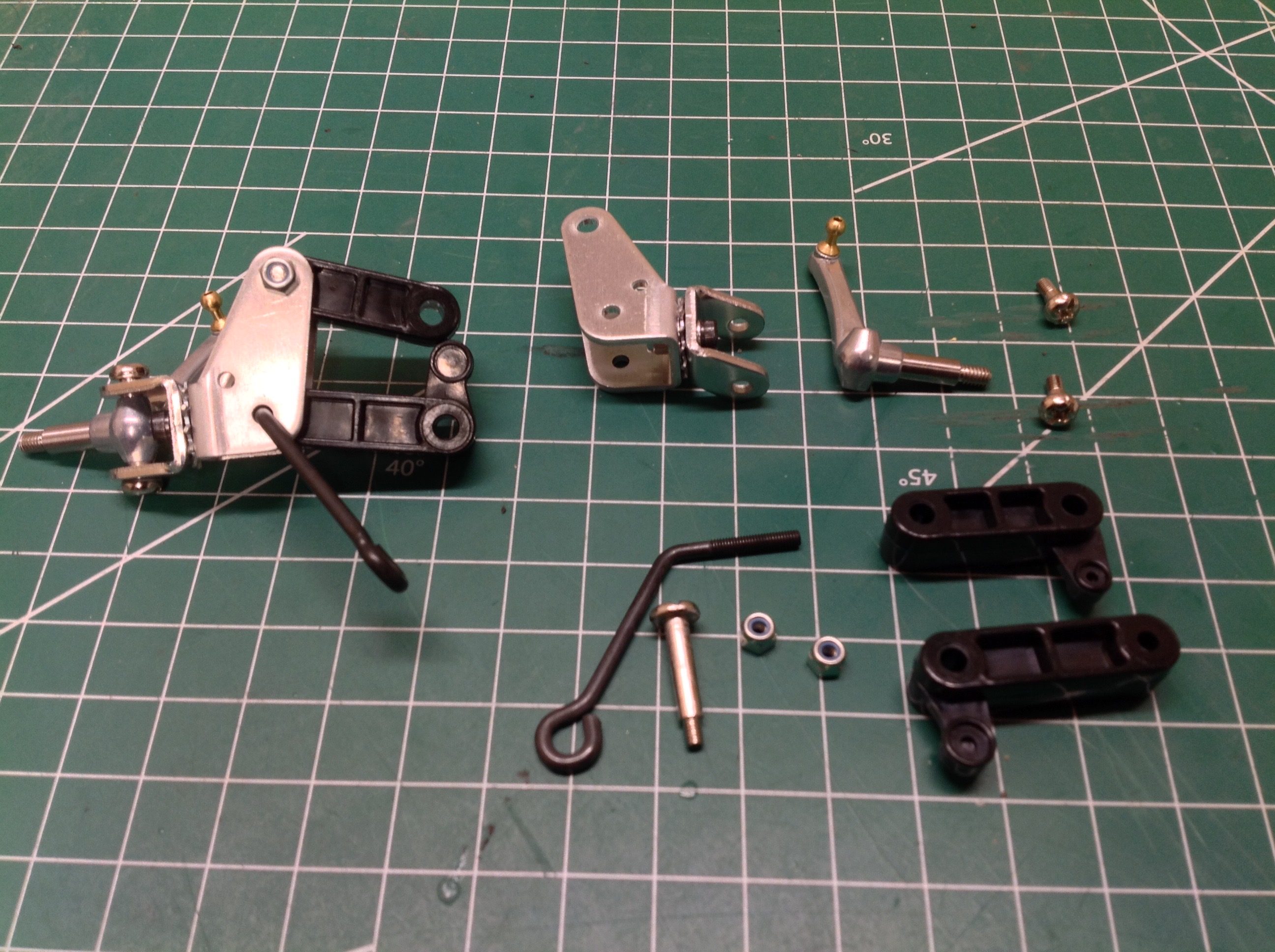
serrated to help grip the washer. On the right you can see the
super short double wishbone suspension arms. Take note of those
L-shaped cranks at the end of the arms. The crank on the lower arm
will support the spring and the crank on the upper arm acts as a down
stop. The steering knuckles are cast metal. The steel wires
are radius arms which support the thrust loads on the front suspension
to help protect the plastic arms.
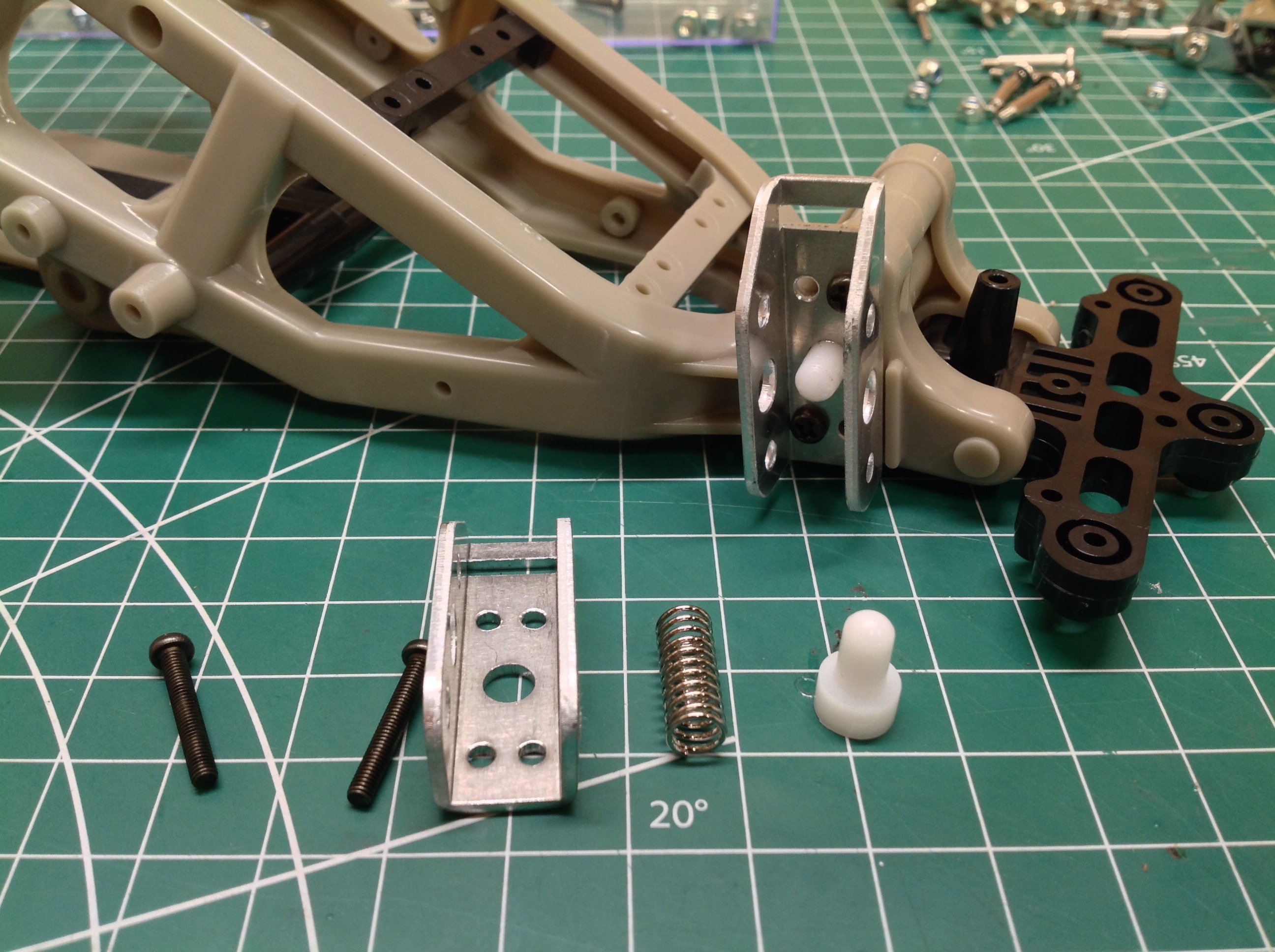
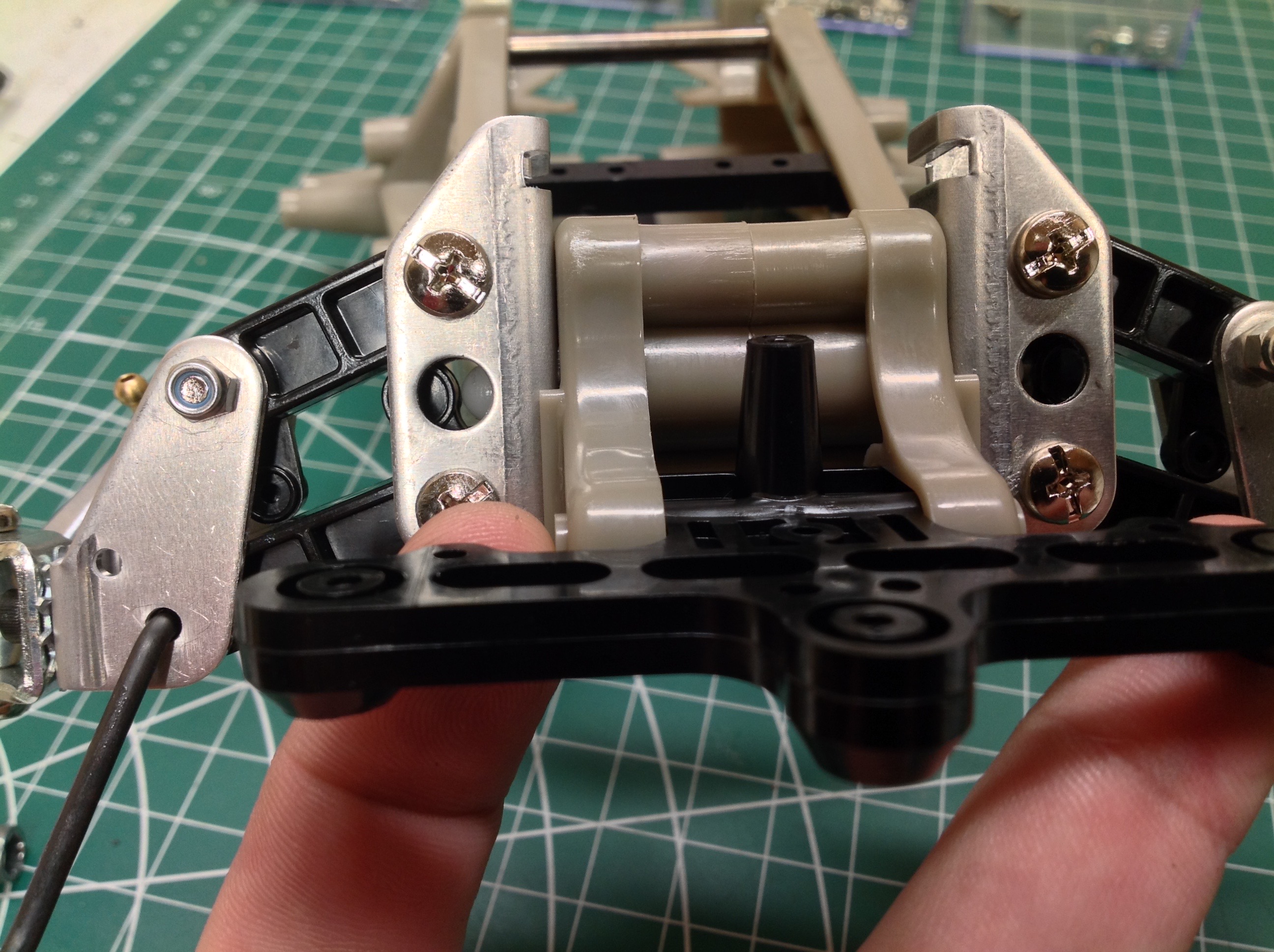
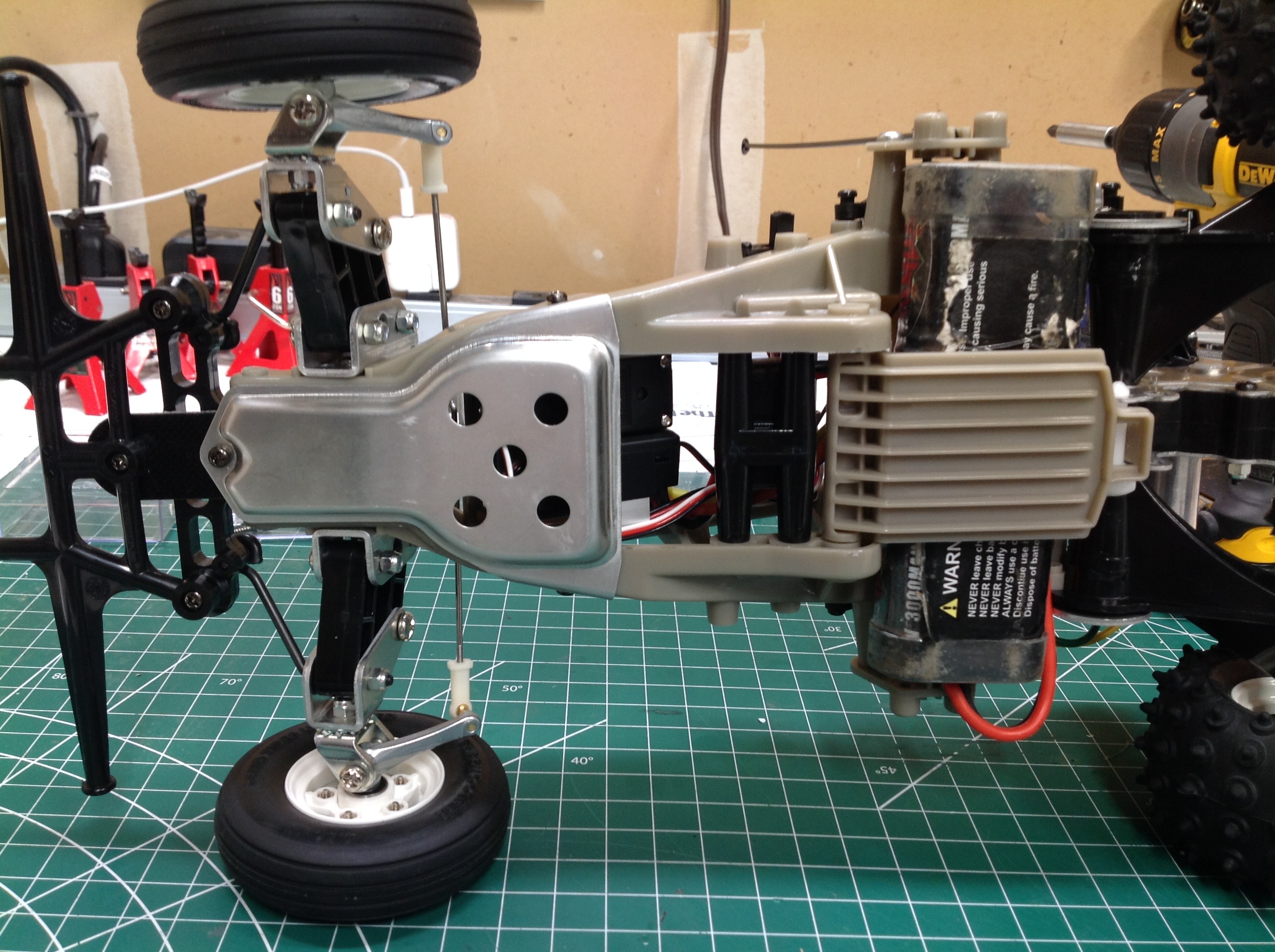
Now we'll delve into the way the front suspension is supported.
There are no coil shocks. A stiff spring sits laterally inside the
chassis frame and pushes a white plastic button as shown. This is
retained by a metal C-channel which will also support the suspension
arms.
From this front view you can see the end of the white button (look
through the hole in the metal part) pushing against the crank on the
lower suspension arm. This drives the arm down. As the
suspension compresses, the button is driven inboard. This results
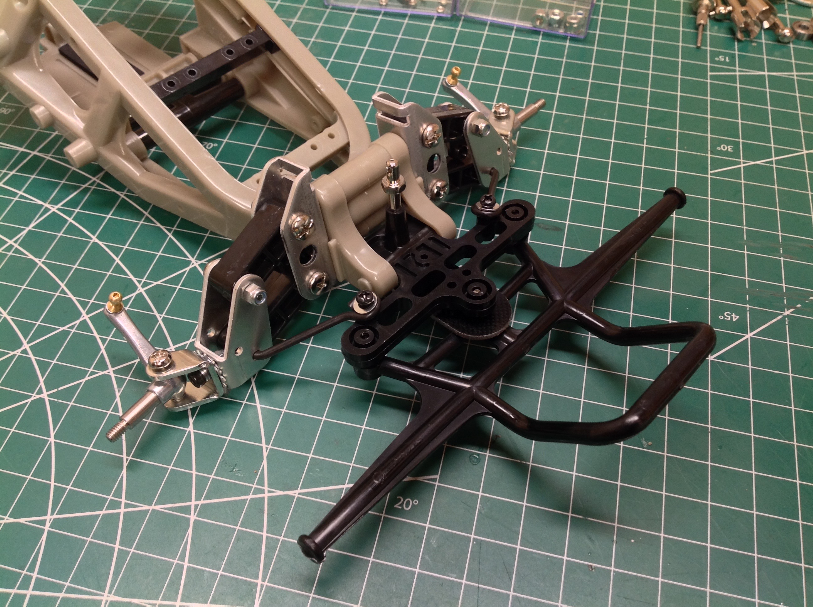
in a compact sprung suspension with no damping. The picture on the
right shows the completed from suspension. So far as I can tell,
this is unchanged from the original Frog, though the front bumper has
gotten stronger and wider.
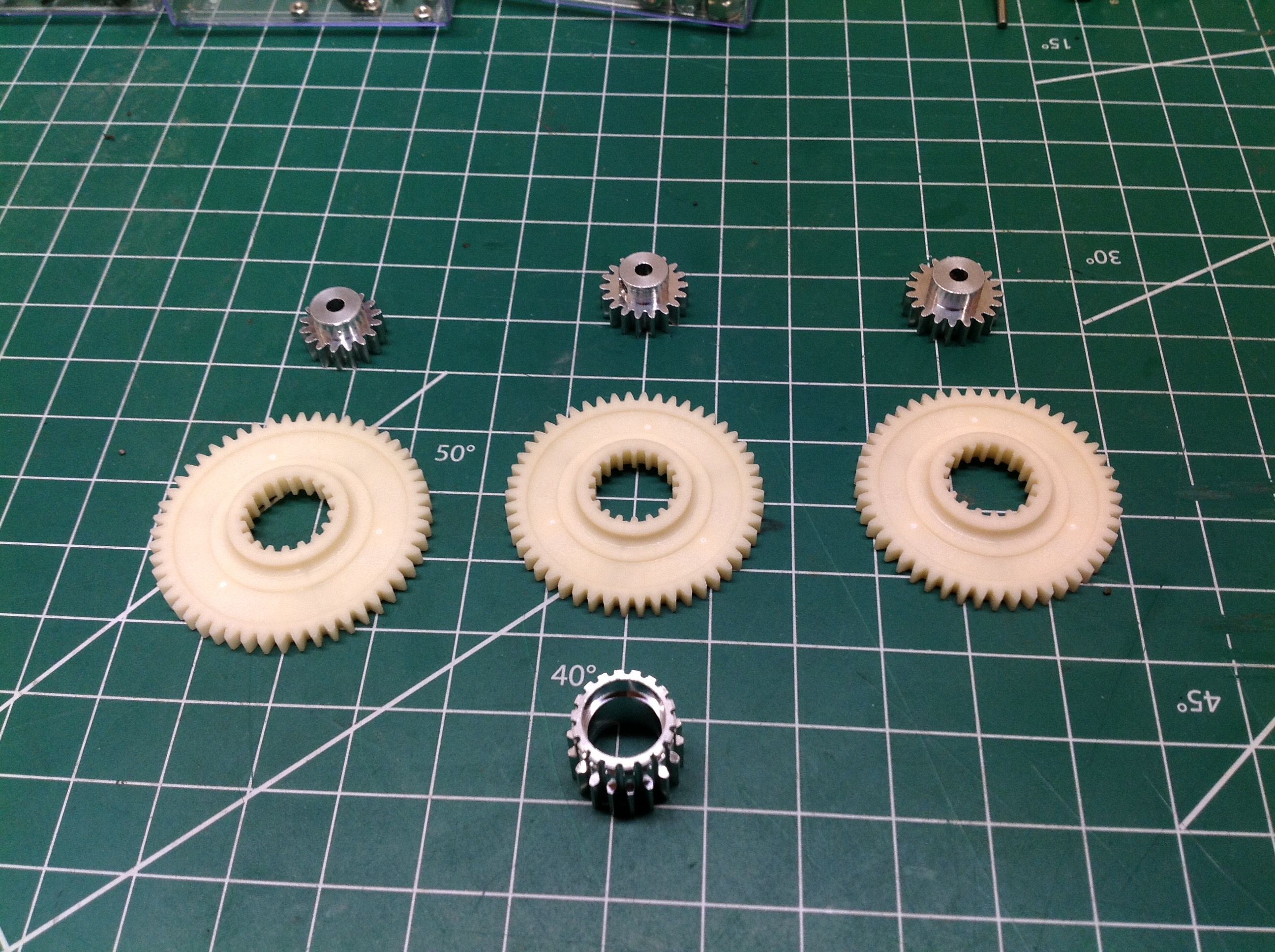
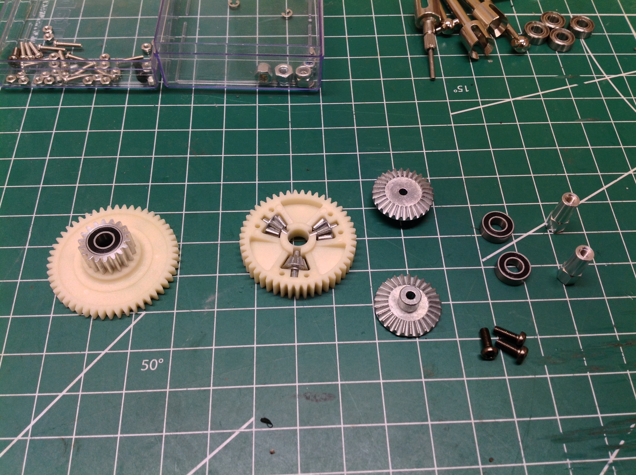
The Frog does not have an adjustable gear mesh, instead there are 3 sets
of spurs and pinions included. The options are 52:16 (8.5:1),
50:18 (7.3:1), and 49:19 (6.7:1). The standard configuration is
the one in the middle which is what I used. An aluminum gear locks
inside the chosen spur with a wire locking ring as shown on the right
next to the differential. The differential spur gear houses 3
metal spider gears with an output bevel to either side. This kit does not include ball bearings so I added them.
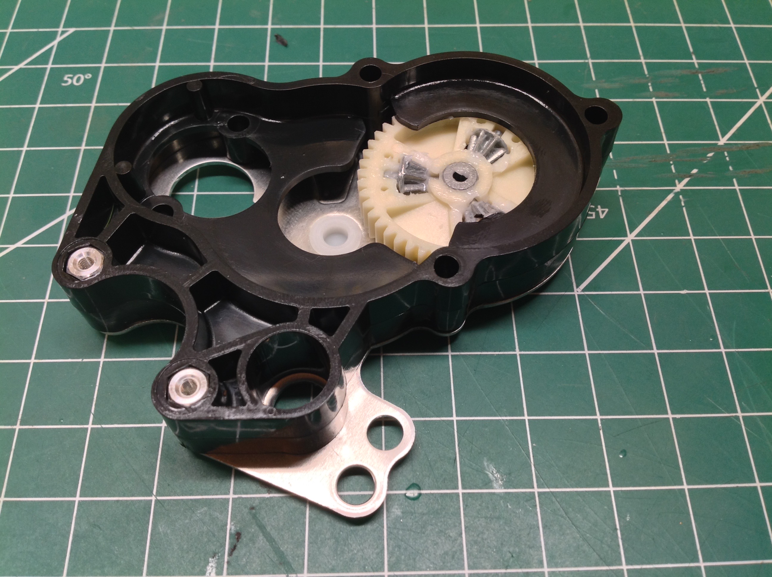
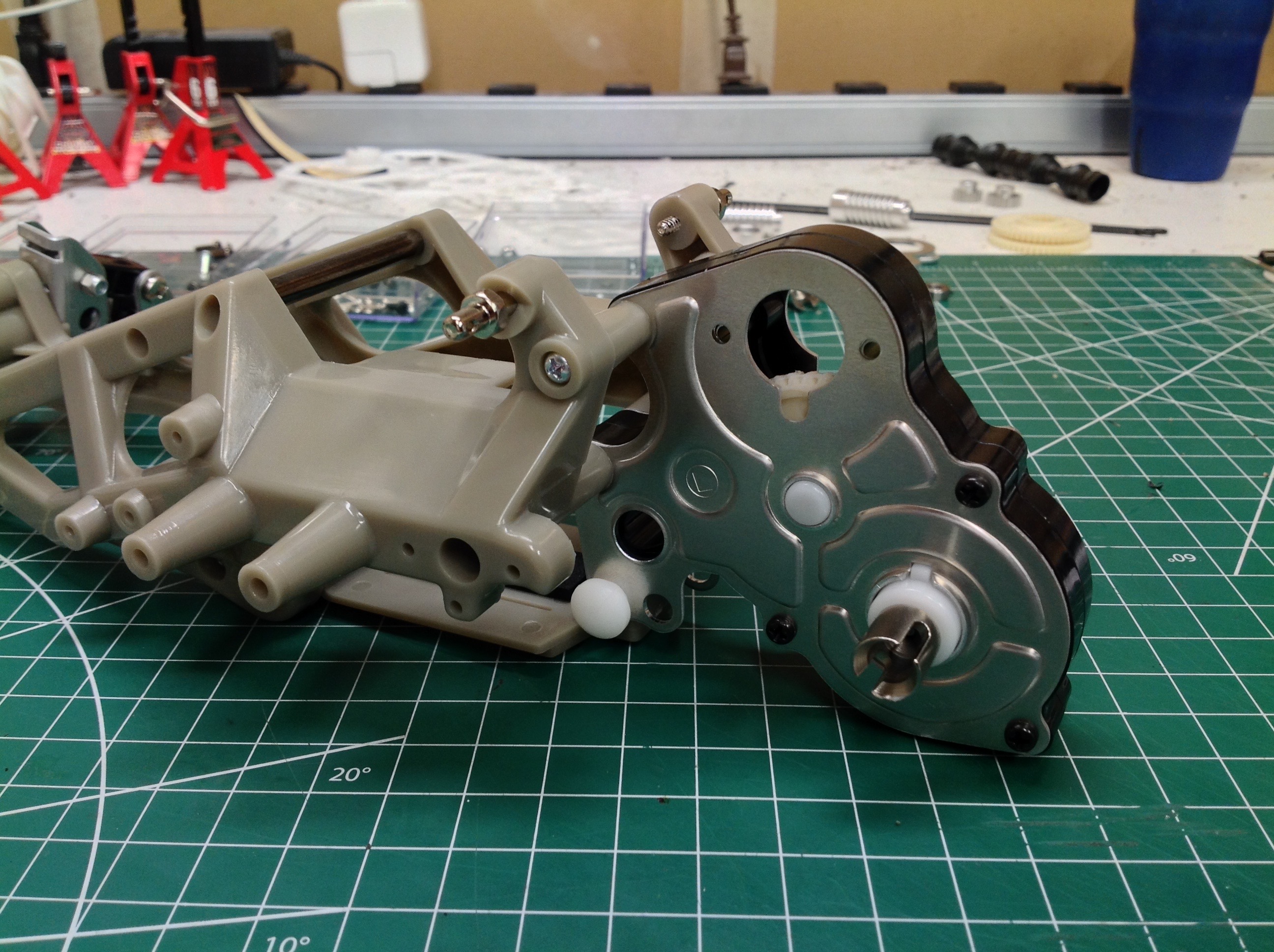
The differential and spur gear then sit inside a narrow plastic gearbox
housing which uses metal closeout plates as shown. In the picture
on the right you can see the locking ring holding the aluminum gear in
place.
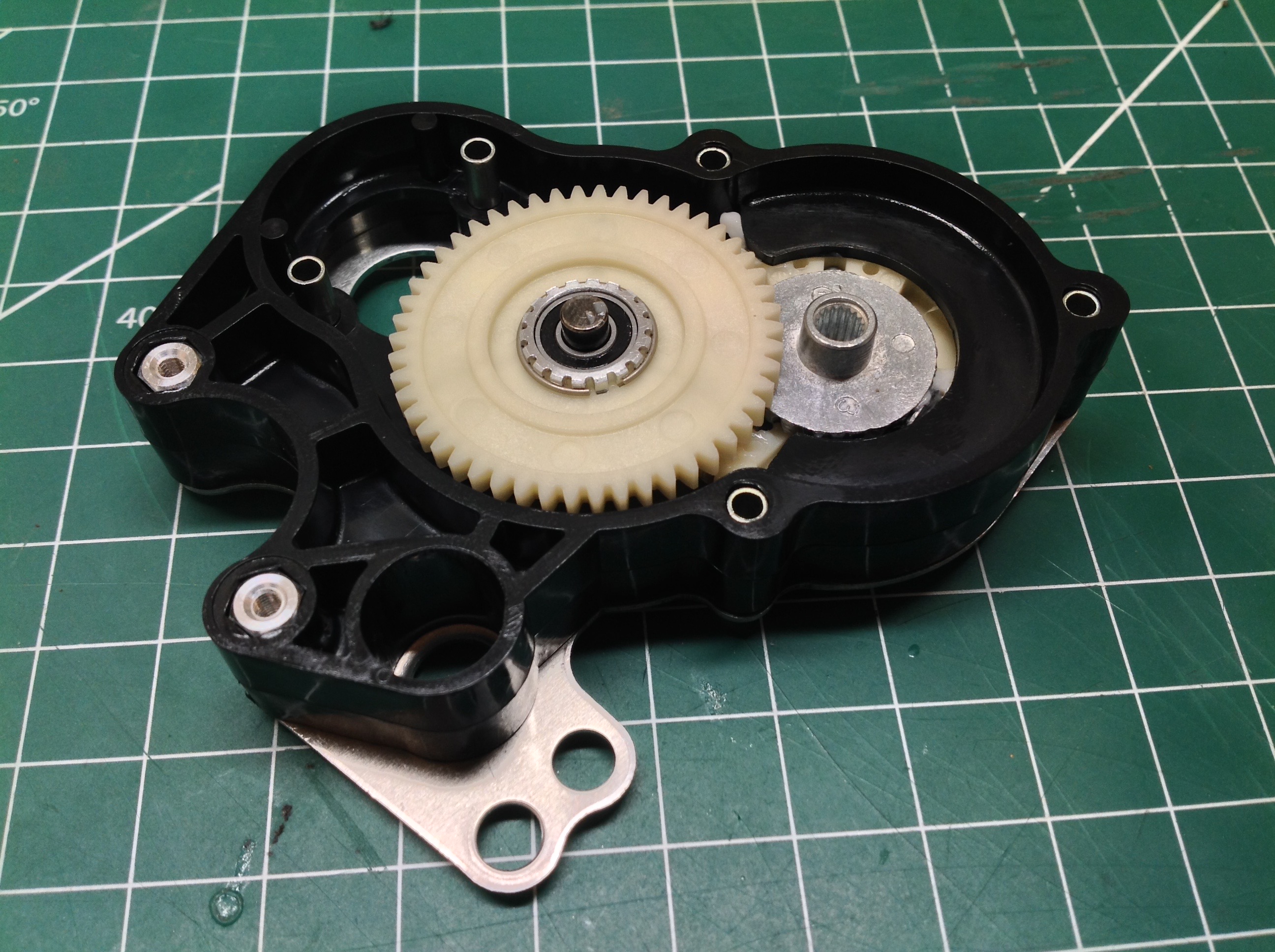
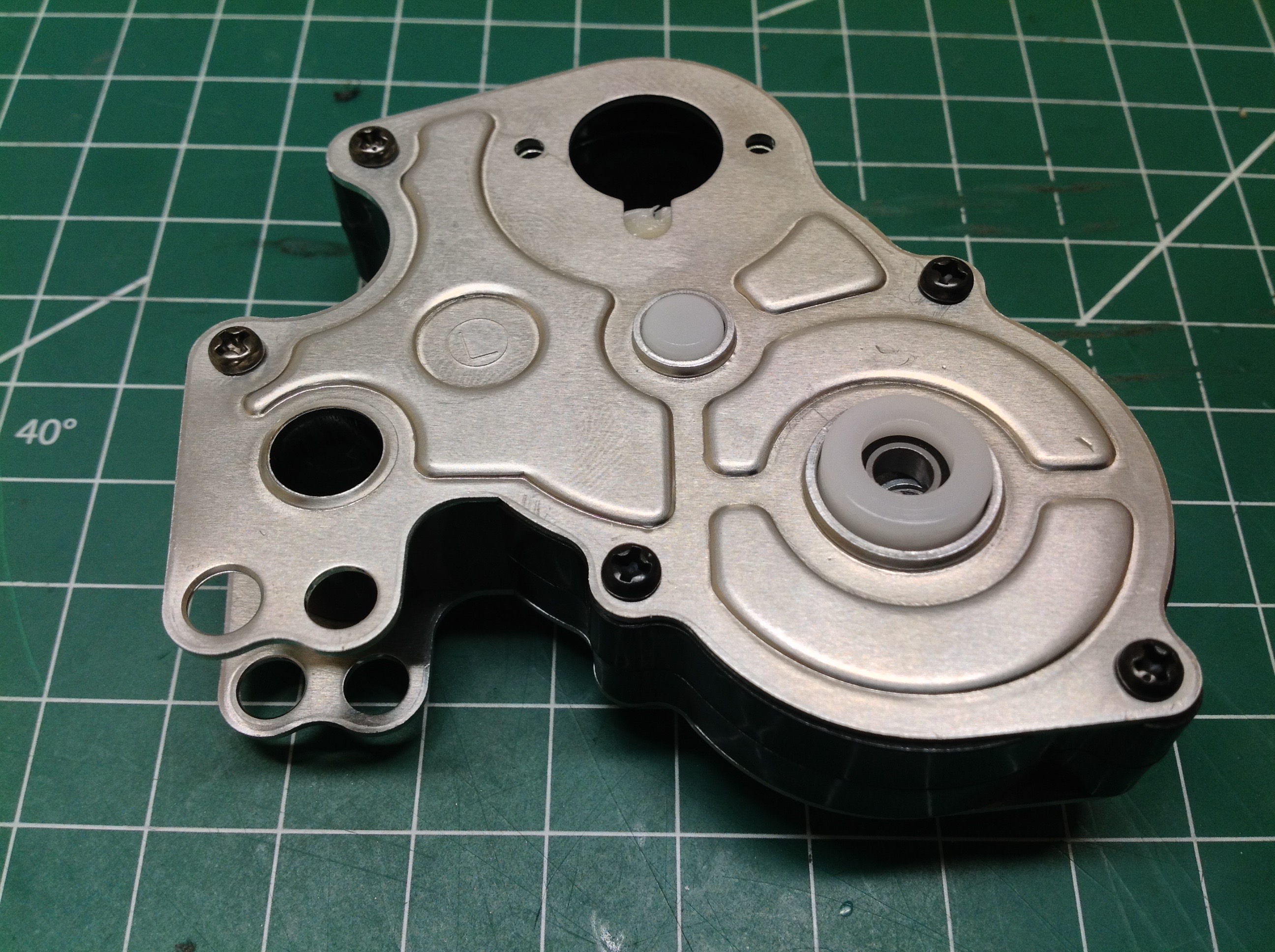
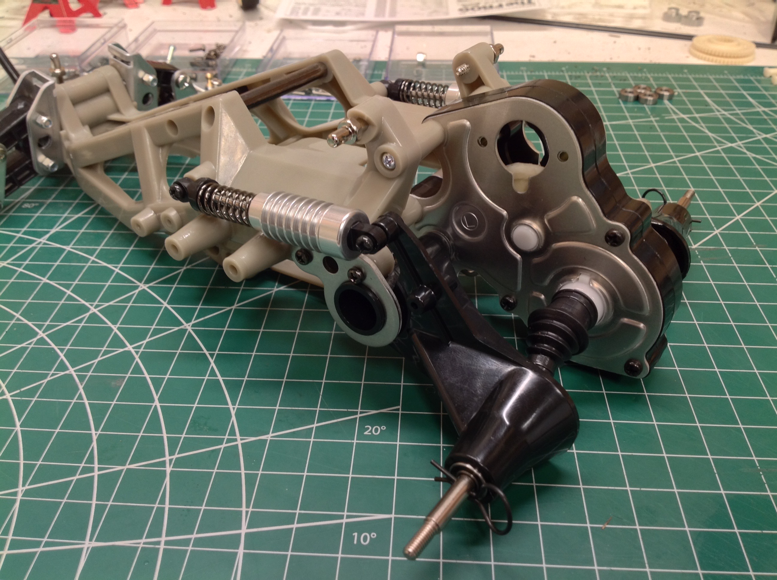
Here's the gearbox fully buttoned up. One flaw of this design is
that the differential gears force the metal side plates outward.
They are not very stiff so this deflection can be enough to cause gears
to skip if the torque is high. On the right you can see the
gearbox sandwiched between the frame halves. The drive cups are
different than the originals. The re-re uses dog bone drive
shafts, but the original shafts were hex drive and were not very
durable.
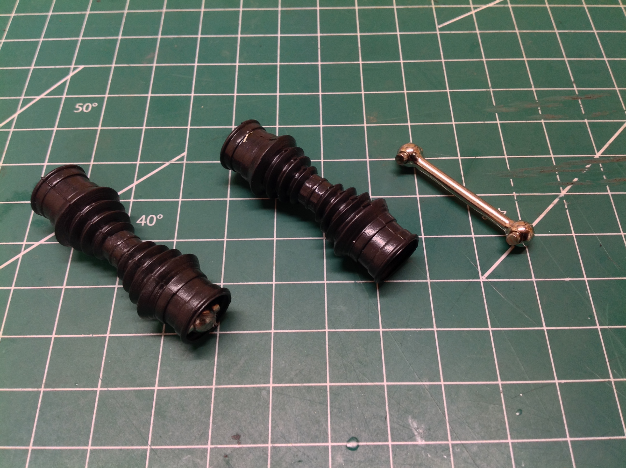
The rubber boots shown slip over the dog bone drive shafts to keep
contaminants out of the joints, and also to look cool. The rear
trailing arms are shown on the right.
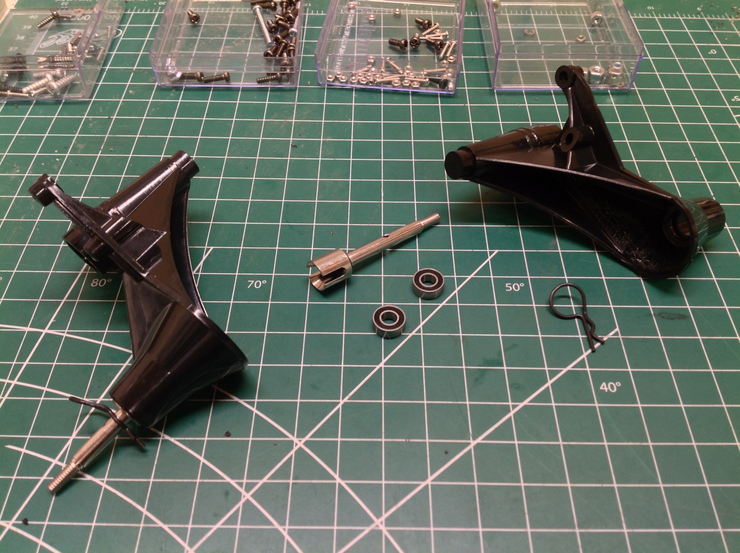
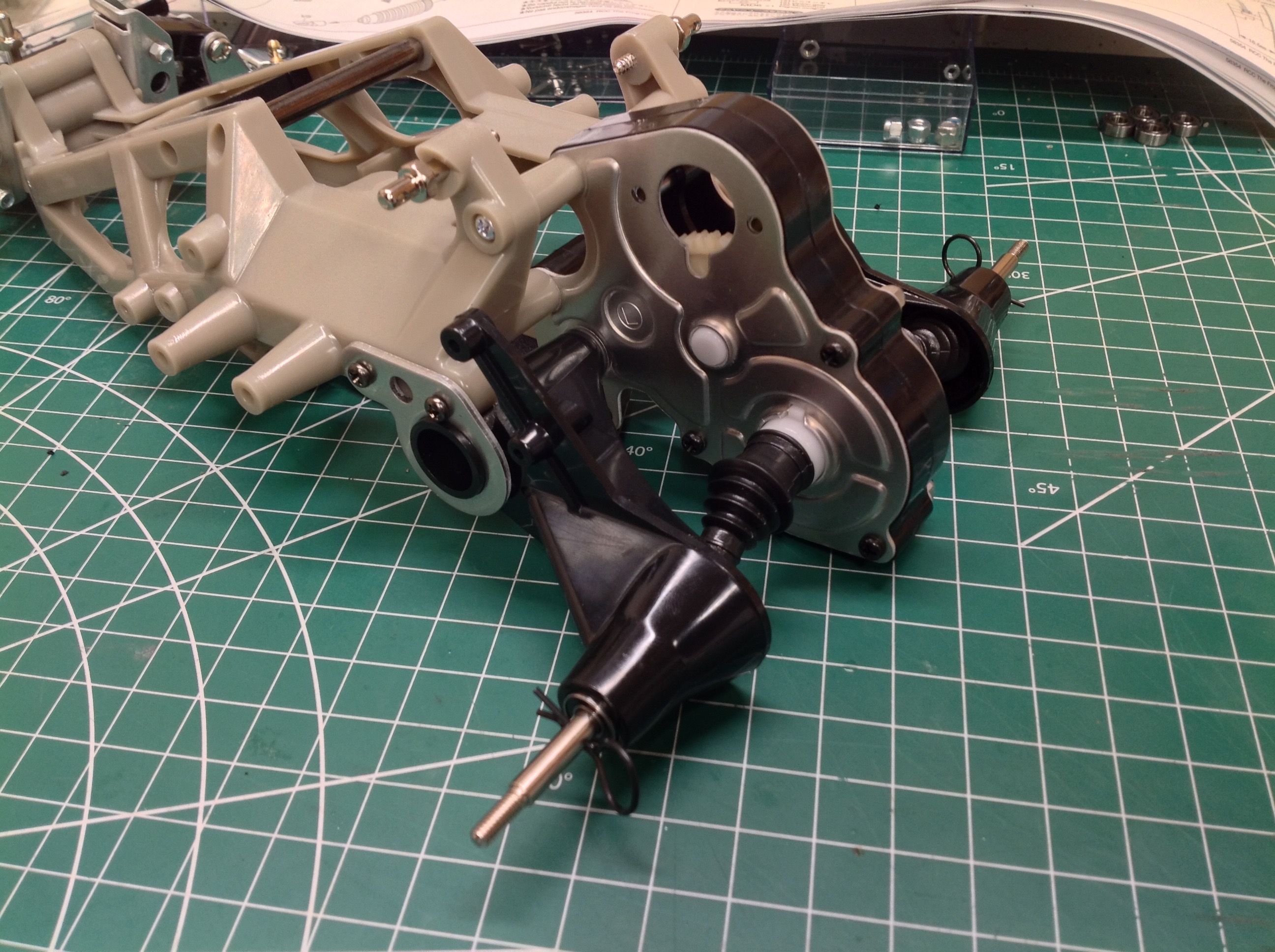
Here the rear suspension has been assembled. The rear trailing
arms pivot on the gearbox on the inboard side and on a sheet metal
bracket on the outboard side. The plastic just rotates in the
metal; there isn't any kind of bearing or even bushing for the
suspension travel.
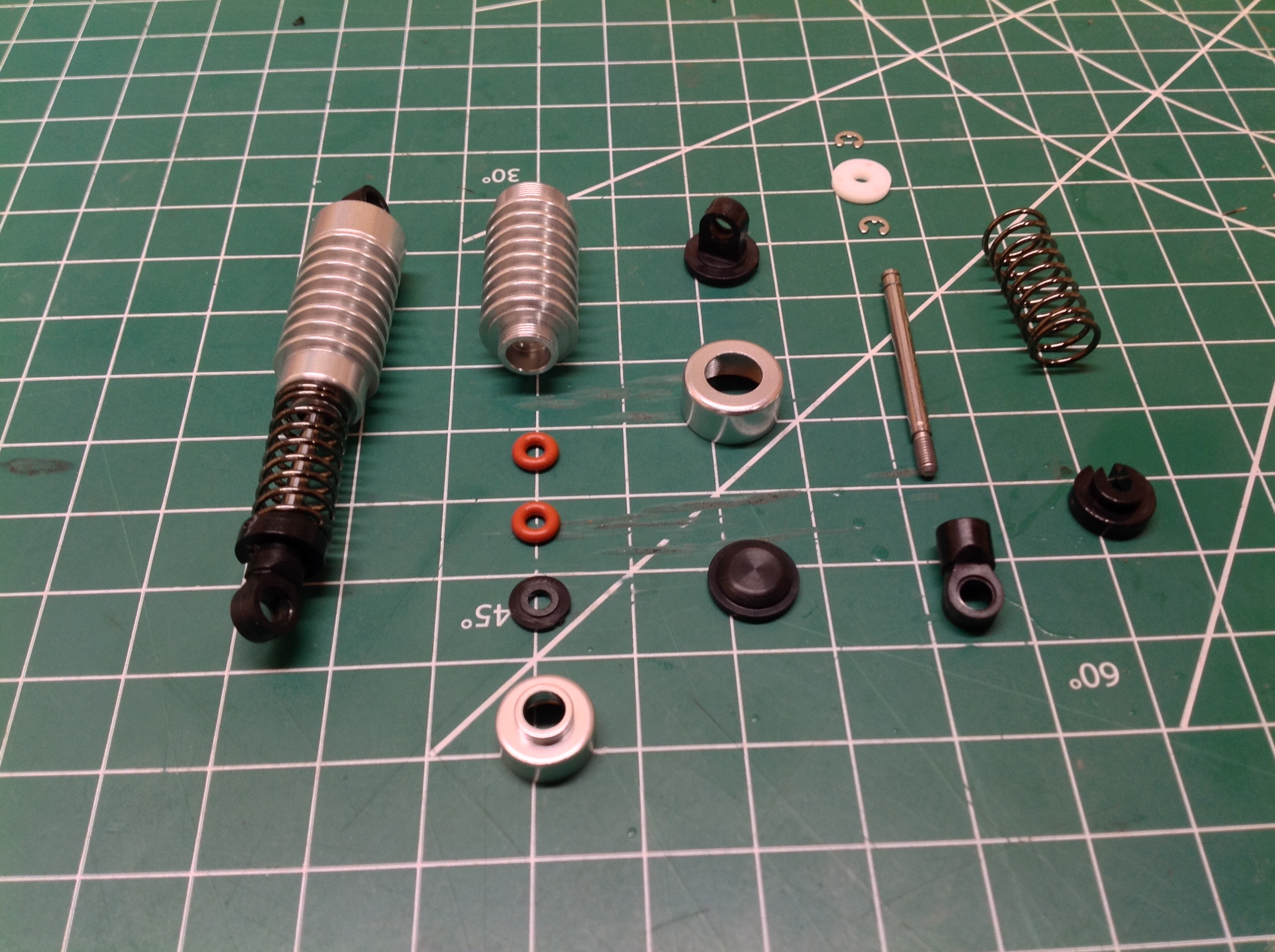
The Frog uses nice aluminum oil filled dampers in the rear which have
changed quite a bit from the originals. The original dampers had
the o-rings and rod guide swaged into the end of the cylinder.
They could therefore not be removed or replaced. There was also a
floating volume compensation piston in the head end. The re-re
dampers are more modern and traditional while retaining the outward
appearance of the originals. They use a threaded rod end cap which
locks the o-rings and a compressible bladder inside the head end.
The complete exploded view is shown on the left. On the right you
can see how the shocks are installed longitudinally and connect to a
crank on the trailing arms. This keeps them very low and obviates
the need for shock tower.
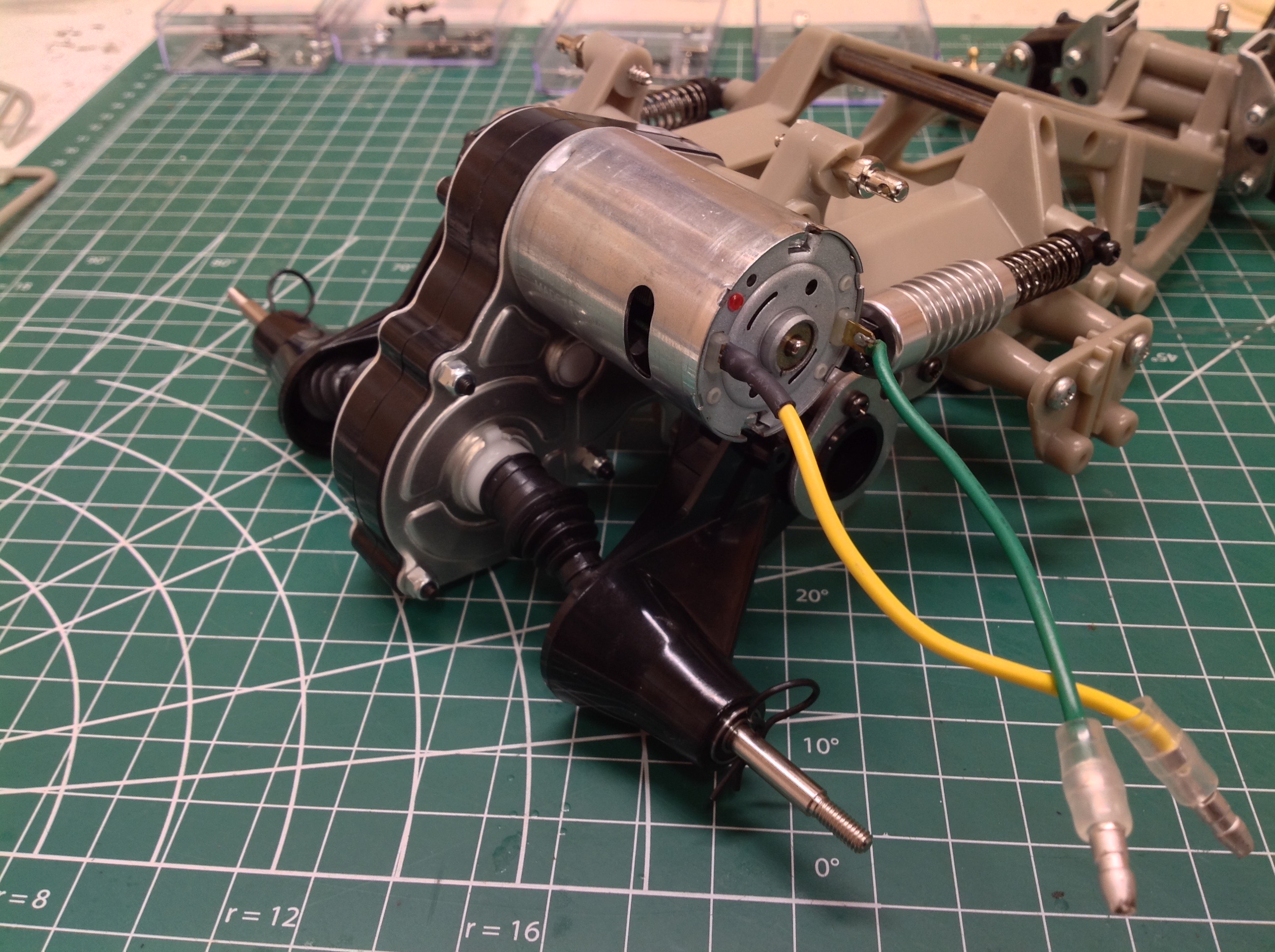
A silver can is plenty of power for a buggy like this. The
original Frog used 2 servos since it needed one for the mechanical speed
controller, but the re-re uses only a steering servo with an ESC where
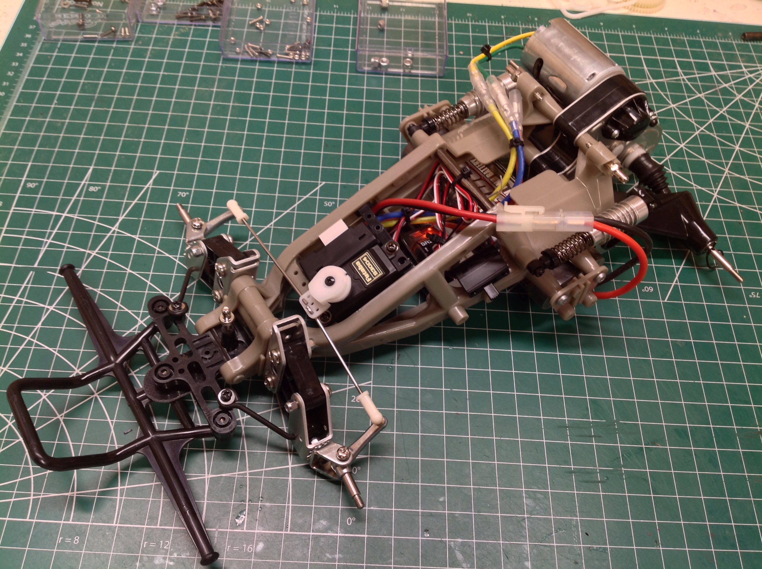
the other servo would have gone. There's a big empty space behind
that where the 4.8V receiver battery would have gone since it is no
longer needed. I tucked the receiver down there out of the way
which seems to have resulted in a pretty clean electronics
installation. The main battery installs from below without the
need to remove the body.
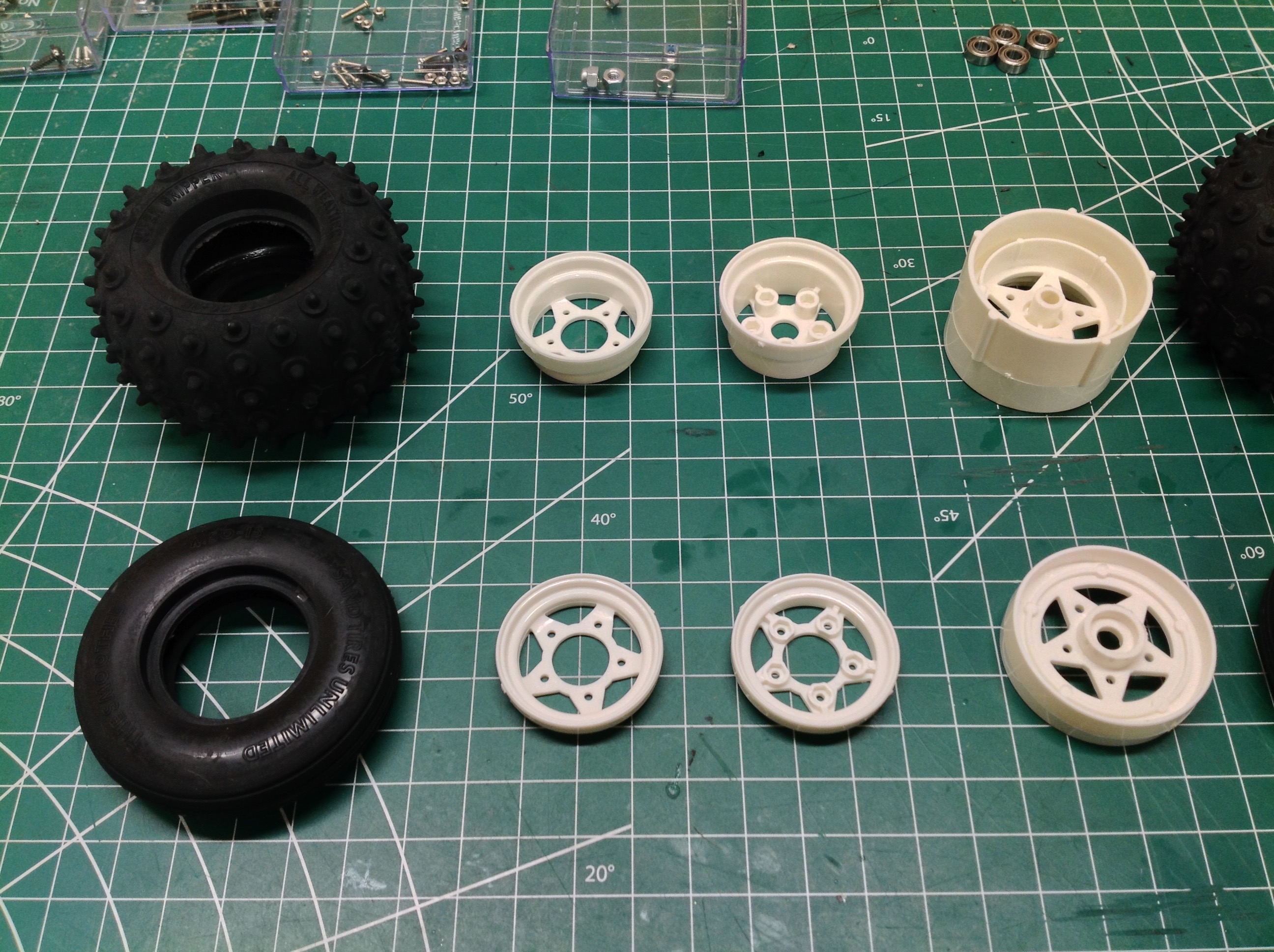
The wheels are a 3-piece clamping design similar to those first used on
the Rough Rider. The basic idea goes all the way back to the
XR311, but those mounted to the vehicle differently. The front
wheels house bearings and the rear wheels slip directly over the drive
pins. From the bottom you can see the metal under tray which protects the servos and the under slung battery.
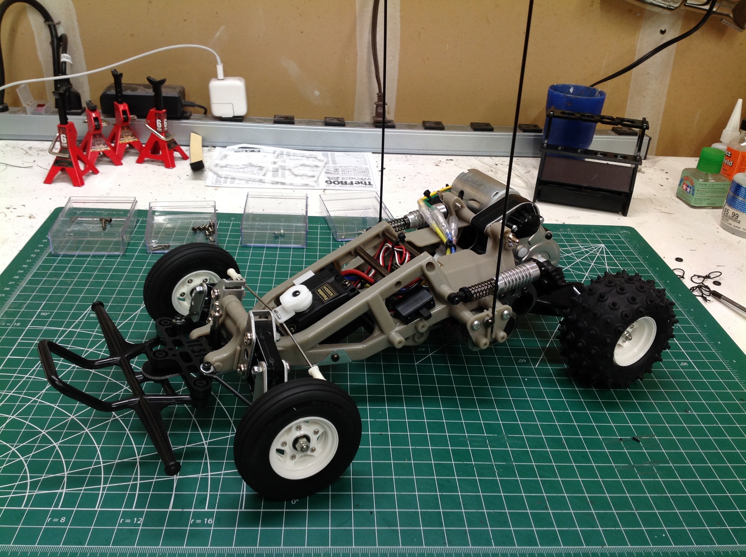
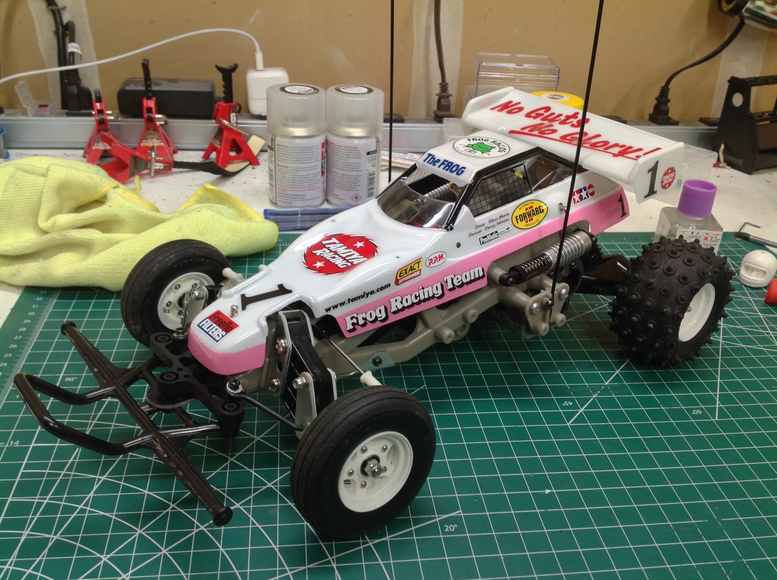
The completed rolling chassis. Note the very simple steering
linkage with the servo saver driving the steering links directly.
The rear wheels have some camber which will not change as the
suspension compresses.
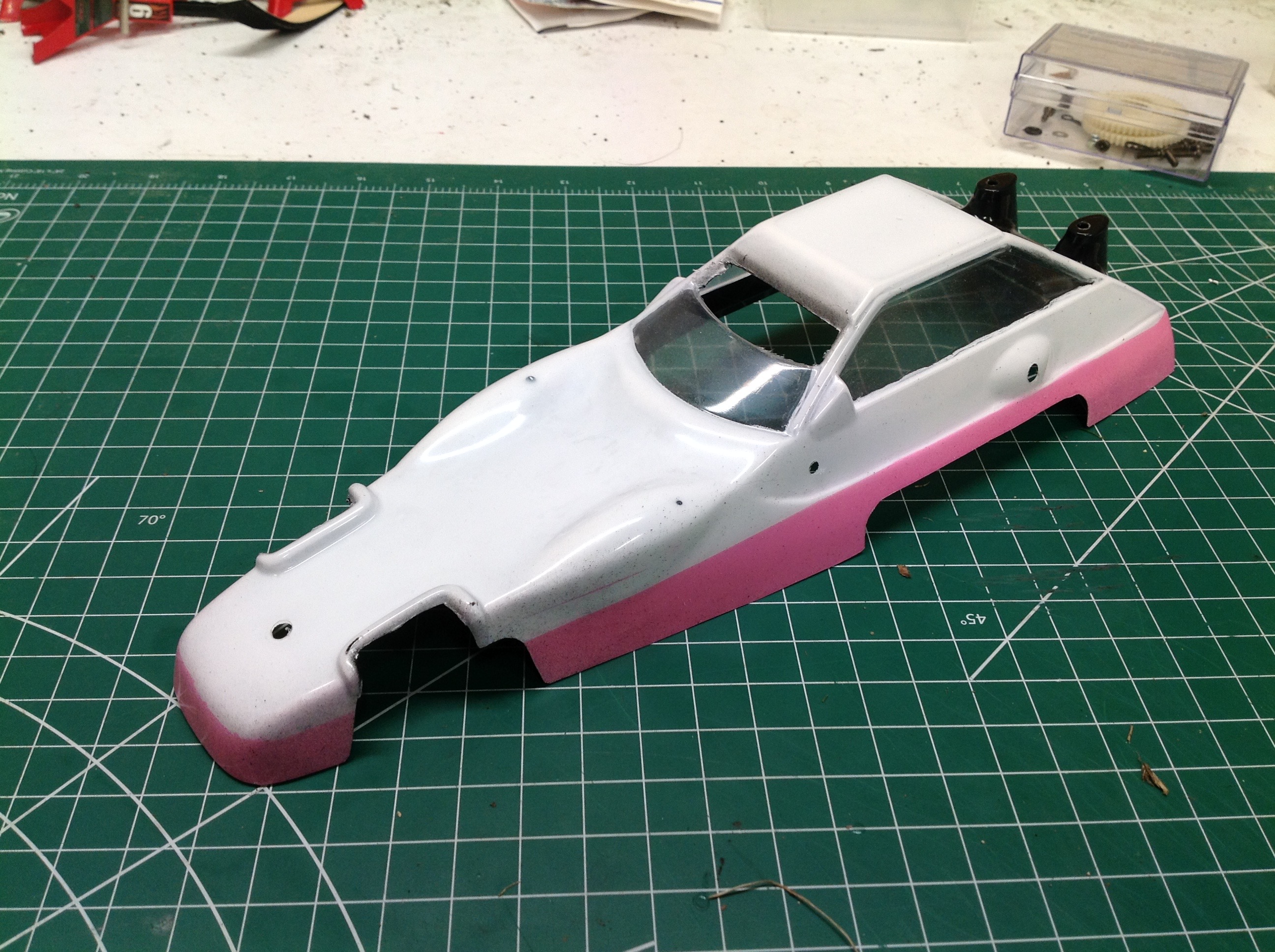
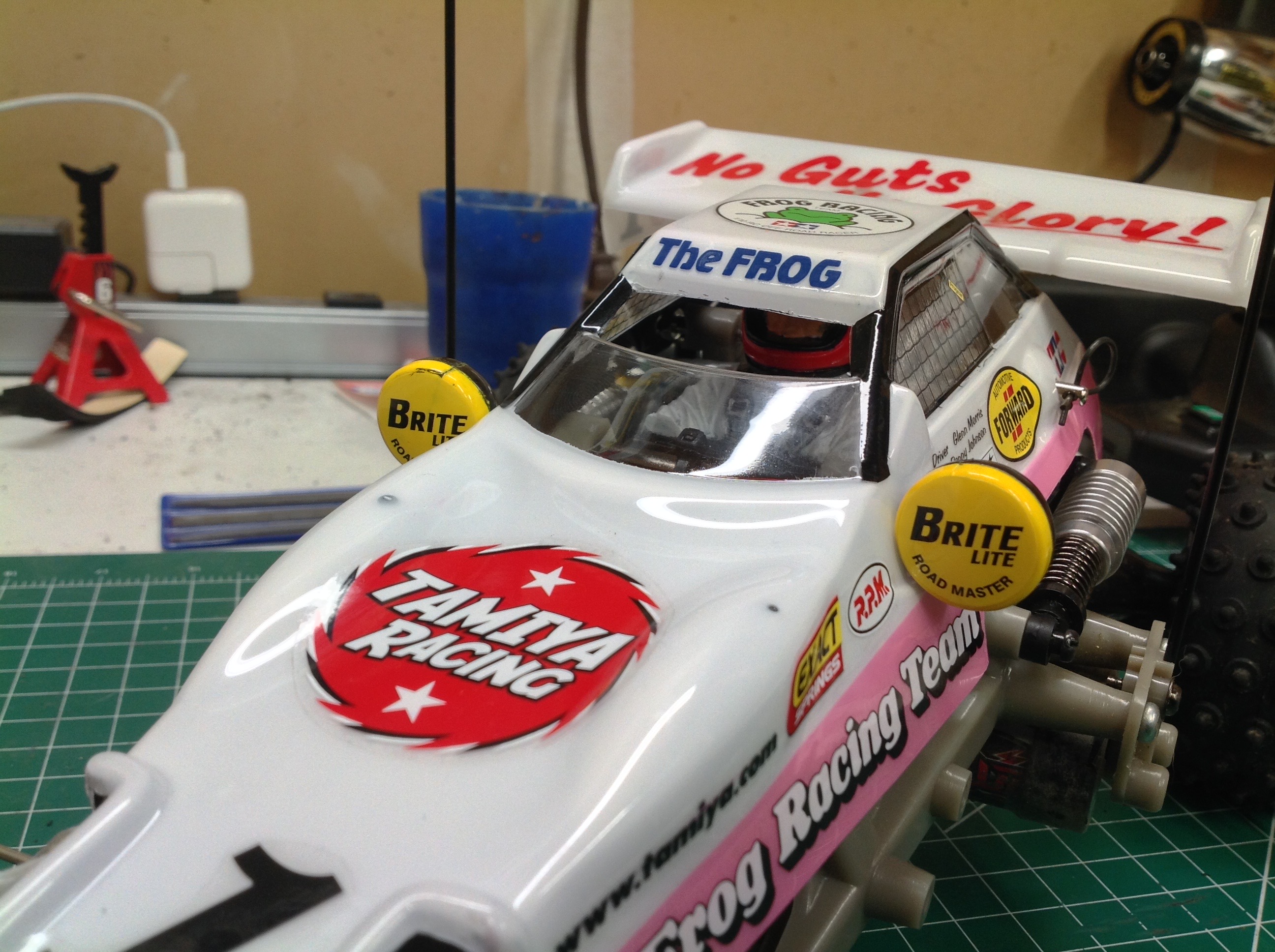
The paint job at first seems very simple but is more complex than it
looks. There is an obvious pink strip along the bottom, but an
area of the windshield must also be masked to remain clear and the back
deck beneath the wing must be black. After the paint is done the
stickers can be applied and the spot lights attached. The wing
attaches directly to the body which makes it very weak. The driver
attaches to the chassis.
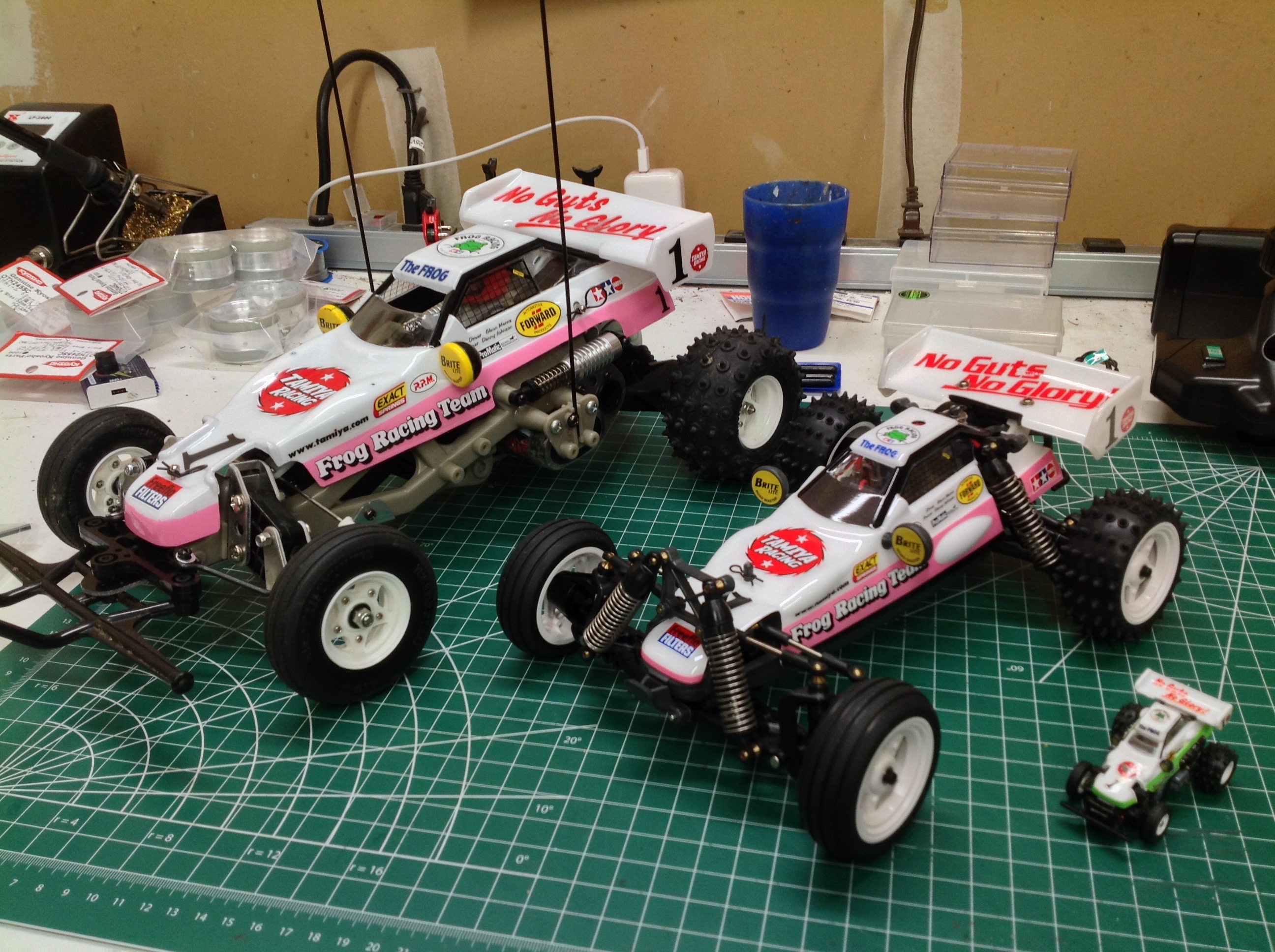
Here's the completed Frog. One of the twin aerials would have been
used as an actual antenna support originally, but here on the re-re
they are just for show. I put them on because they are a component
of the classic look of the Frog. On the right you can see a
comparison with the smaller TamTech Gear version and the tiny Takara
Tomy version.
©2020 Eric Albrecht