Tamiya Monster Beetle Trail Project
Page 1: Assembly
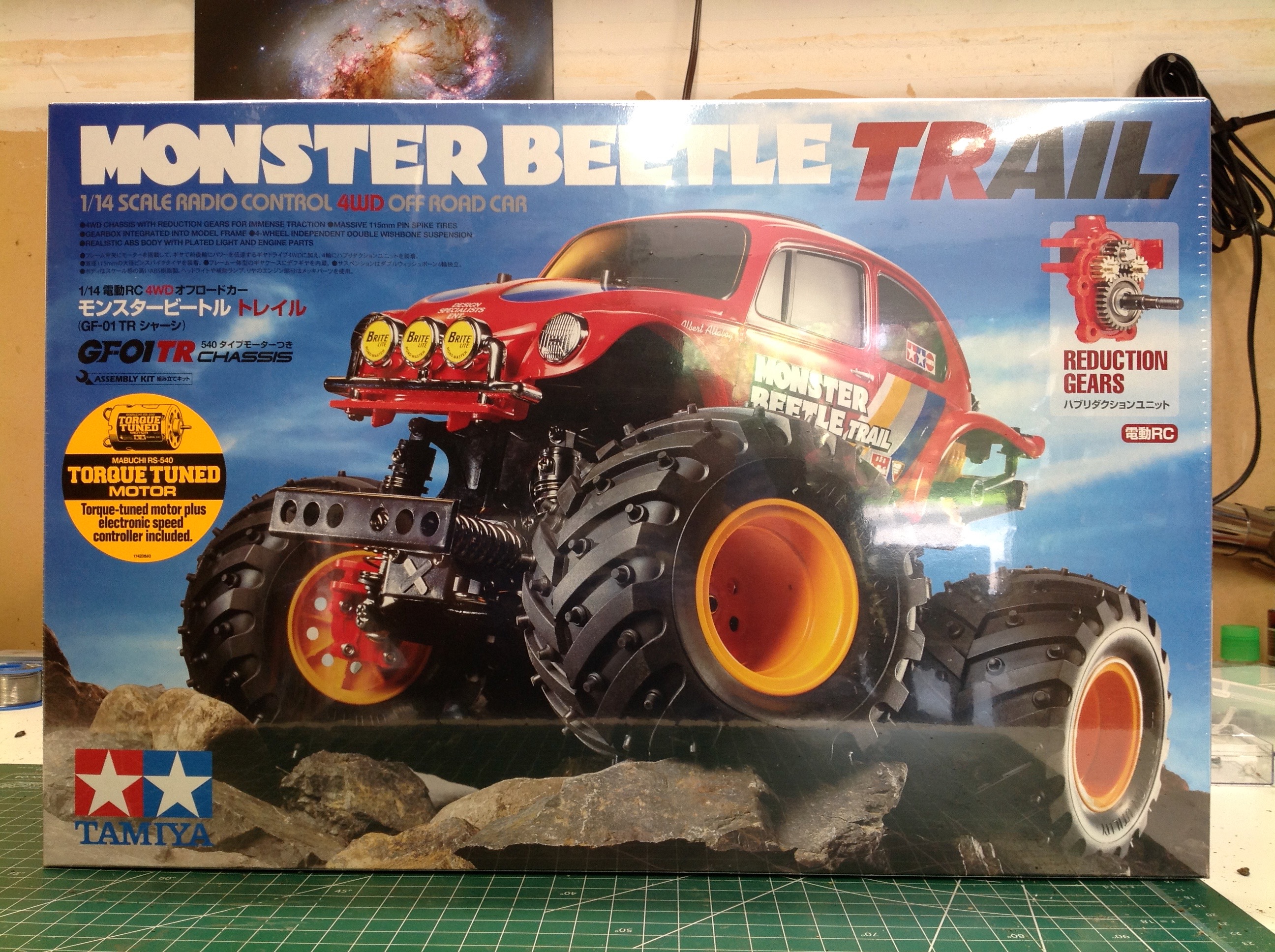
The Monster Beetle Trail comes in a surprisingly large box for what I
thought would be a small model. It turned out to be much bigger
than I expected. The contents of the box are divided into three
sections with the body on the left and the tires on the right.
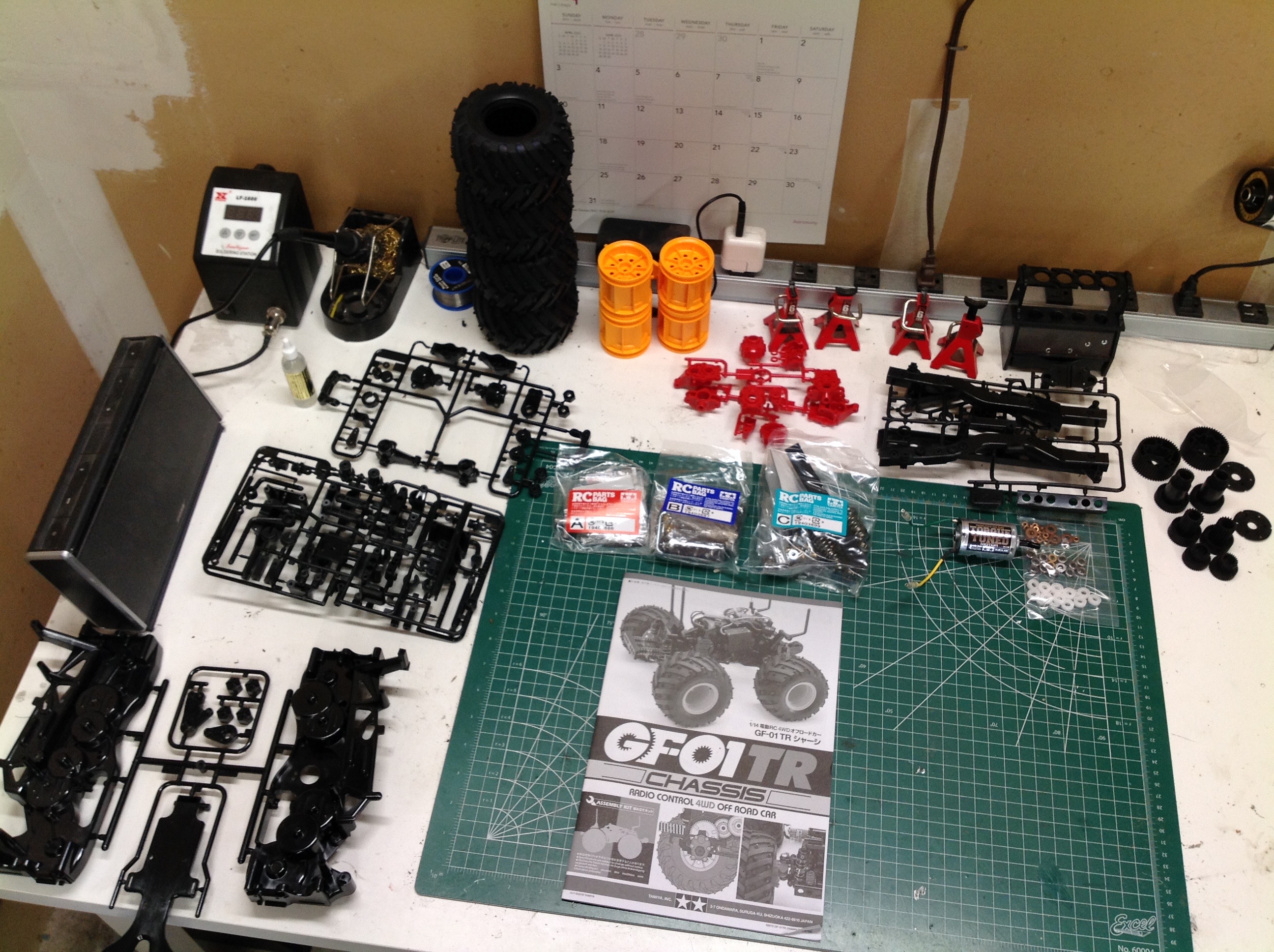
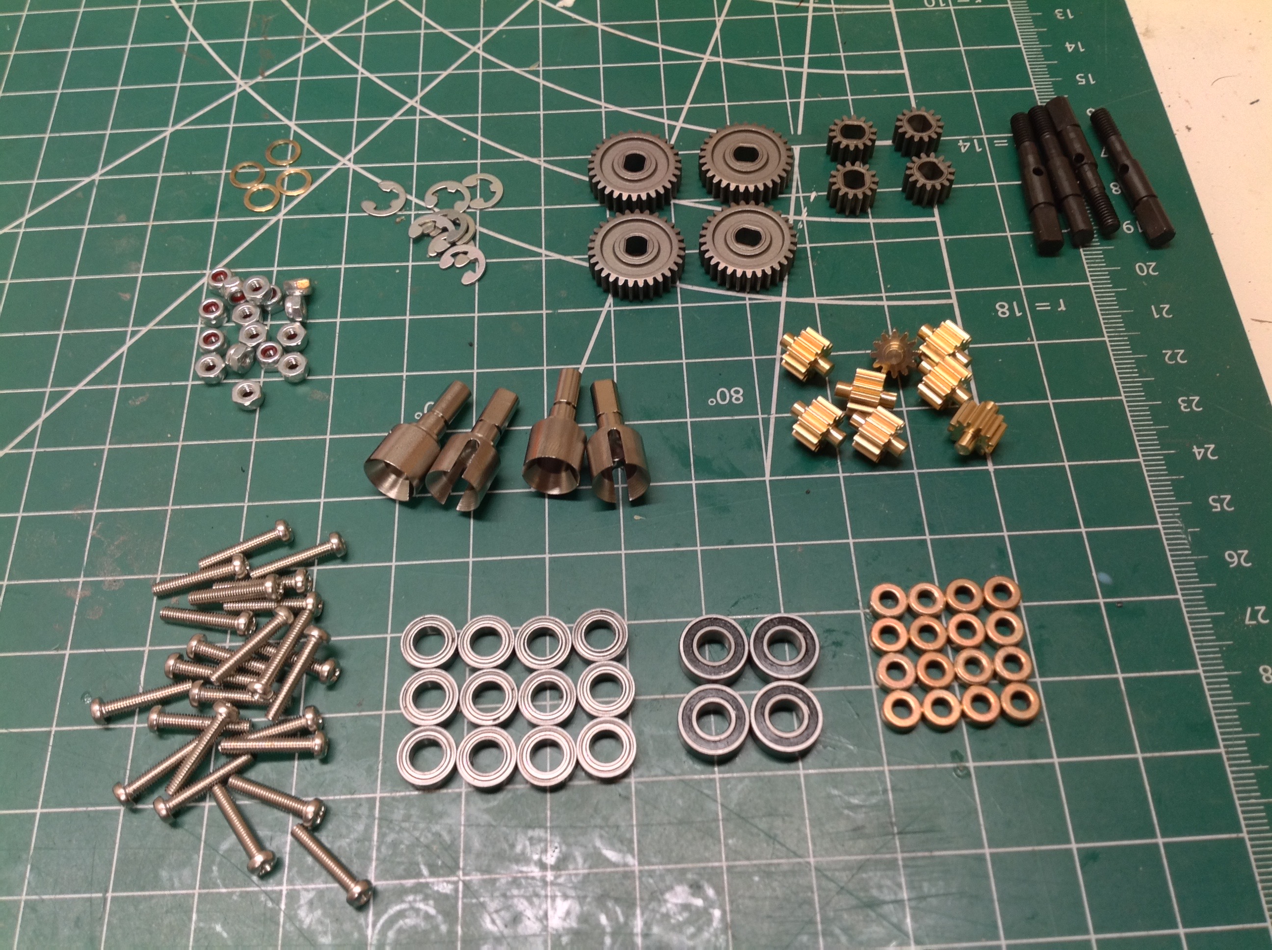
Here are the parts trees arranged on my building table. Apart from
those, there are three labelled hardware bags, a torque tuned motor, an
assortment of gears, and a mixture of ball bearings, metal bushings,
and plastic bushings. My plan was to upgrade to full ball bearings
throughout, but I later found that my "complete" bearing kit was not
complete. More info on that later.
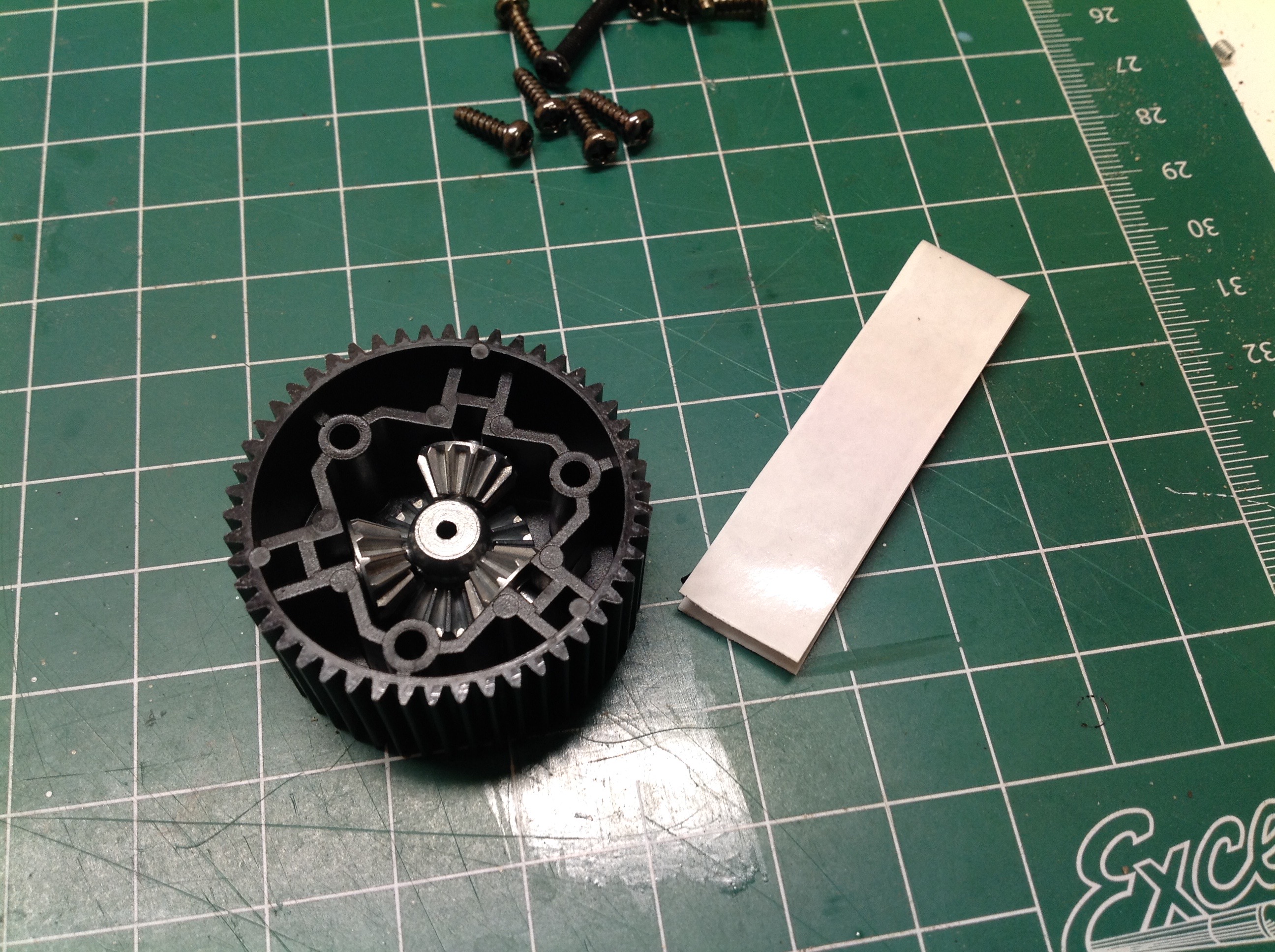
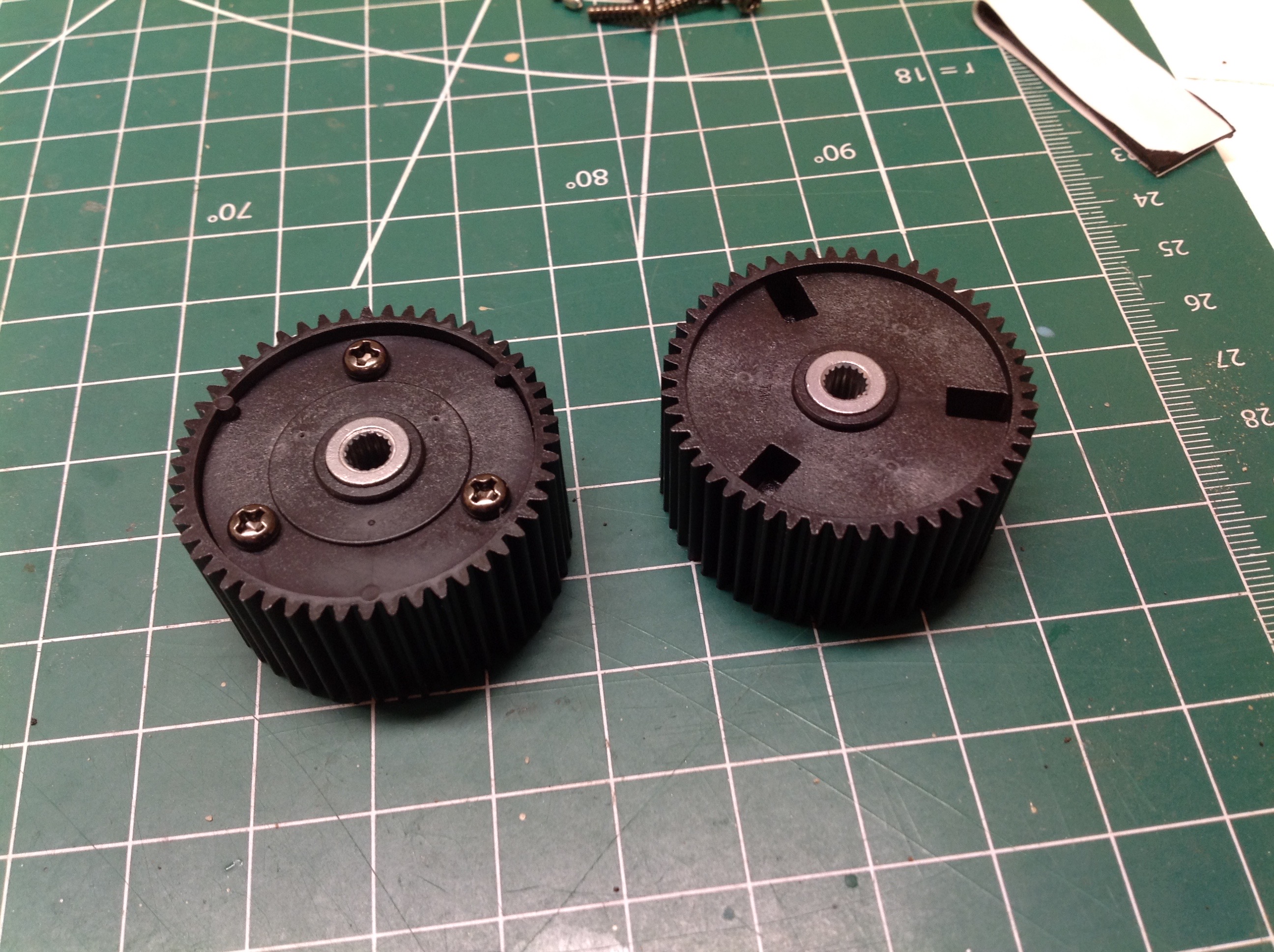
The build begins with the huge dual differentials. Each
differential housing has a spur gear on the outside diameter and a set
of three metal bevel spider gears on the inside. Outputs are
internally splined shafts. Front and rear differentials are
identical. These are unsealed units so they would normally get
some grease but not be filled with oil. In this case though, the
differentials are locked by putting a small ball of stiff putty inside
each. The white "tape" shown on the left contains the putty.
This results in an effectively locked diff, but still with enough
compliance to absorb some impact and protect upstream gearing and axles.
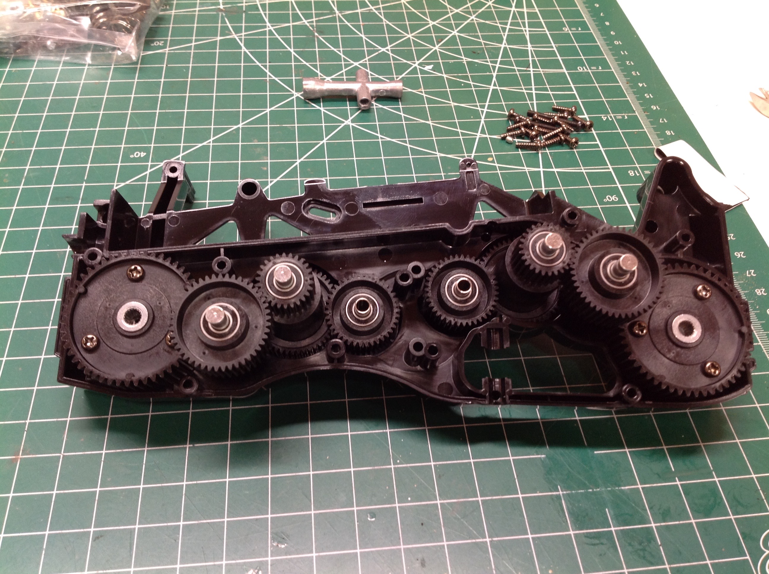
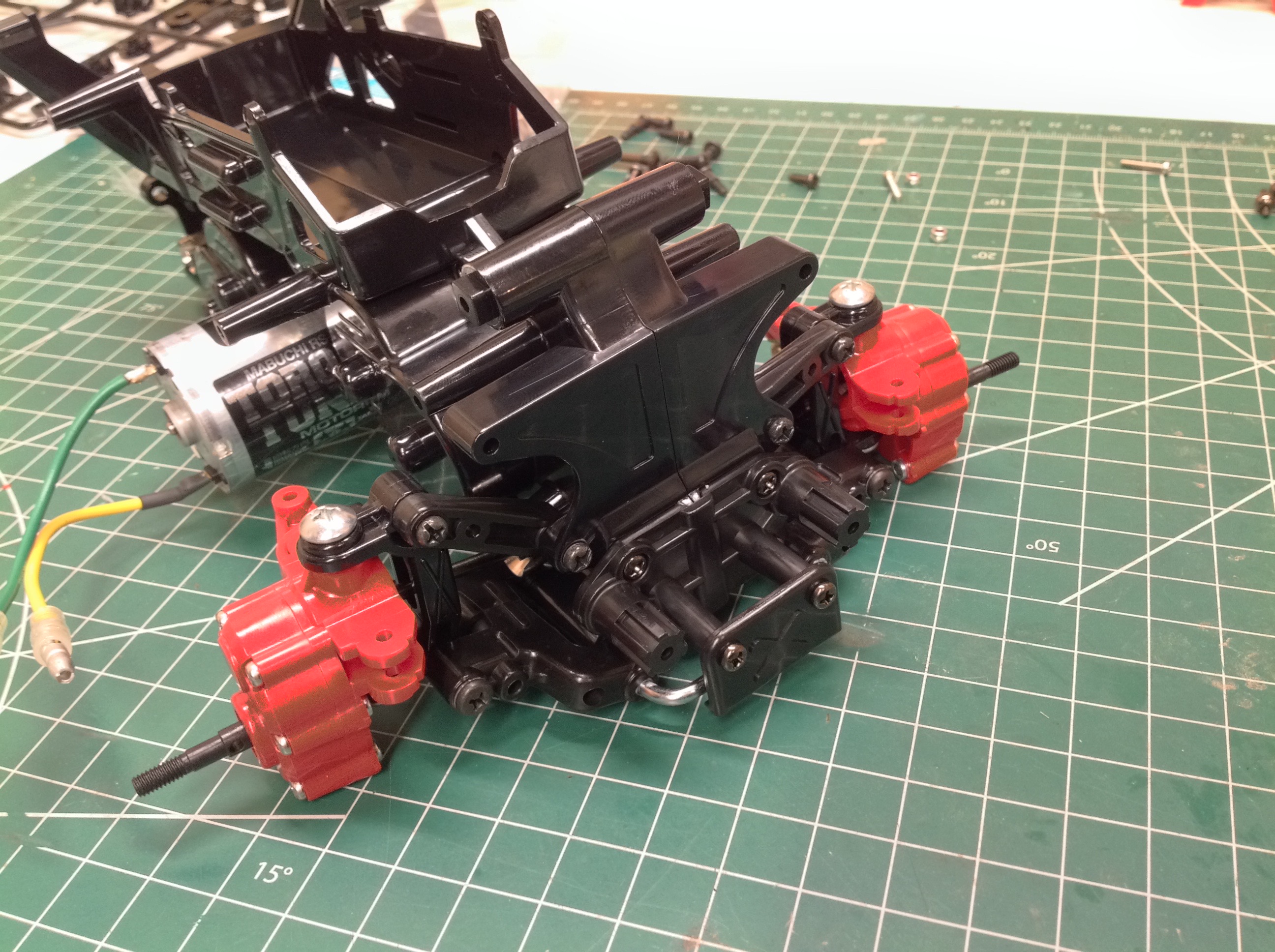
This chassis is just one giant gearbox filled with spur gears. The
differentials sit at the ends as shown. There are then three sets
of gear reduction, identical front and rear, until we get to a gap in
the center. This is where the motor pinion will sit, engaging both
front and rear gear trains in parallel. 16 ball bearings are
required to support all of this. The results is a solid chassis
with incredible bending stiffness due to its vertical height, and great
torsional stiffness due to its large cross section.
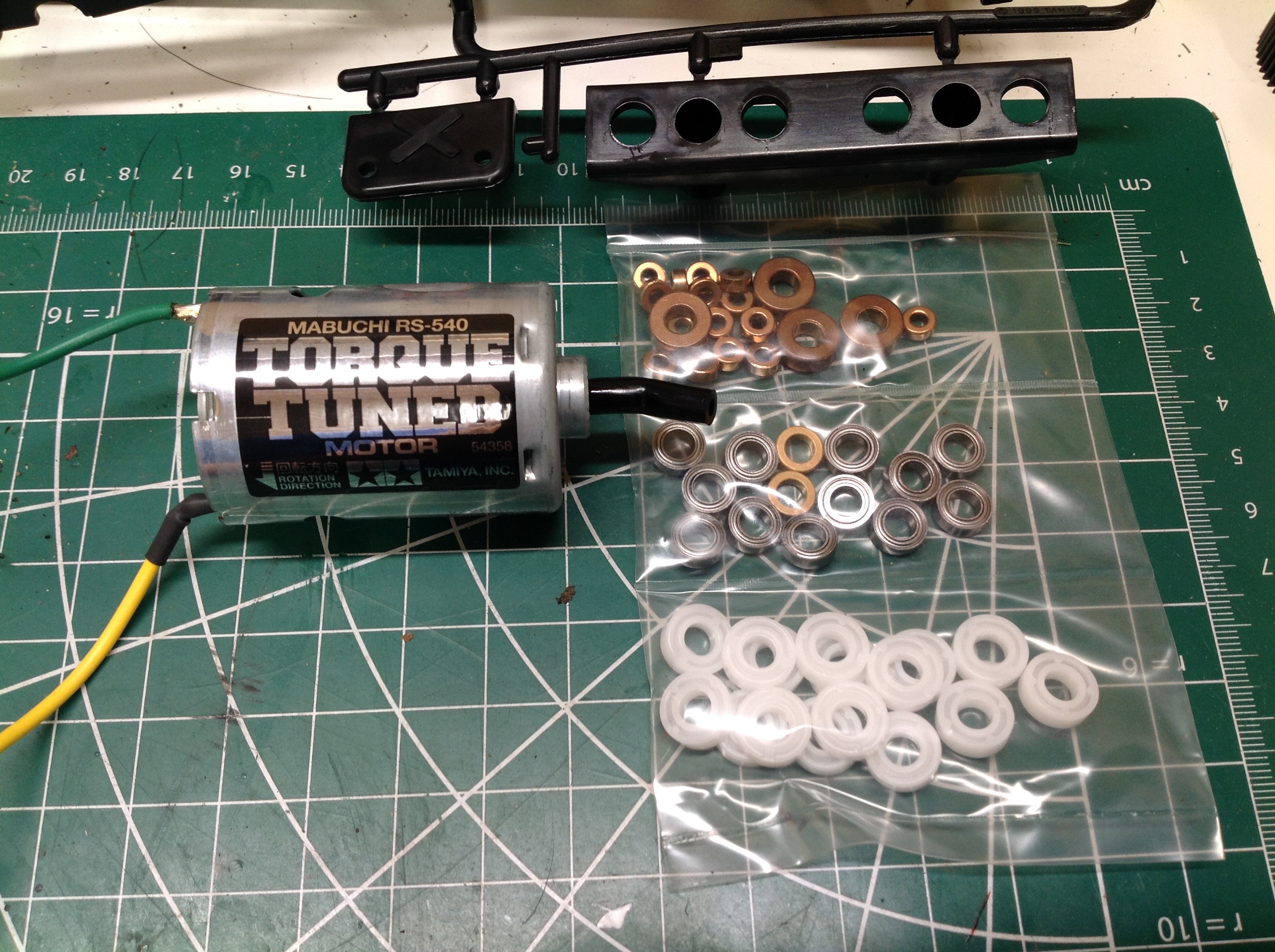
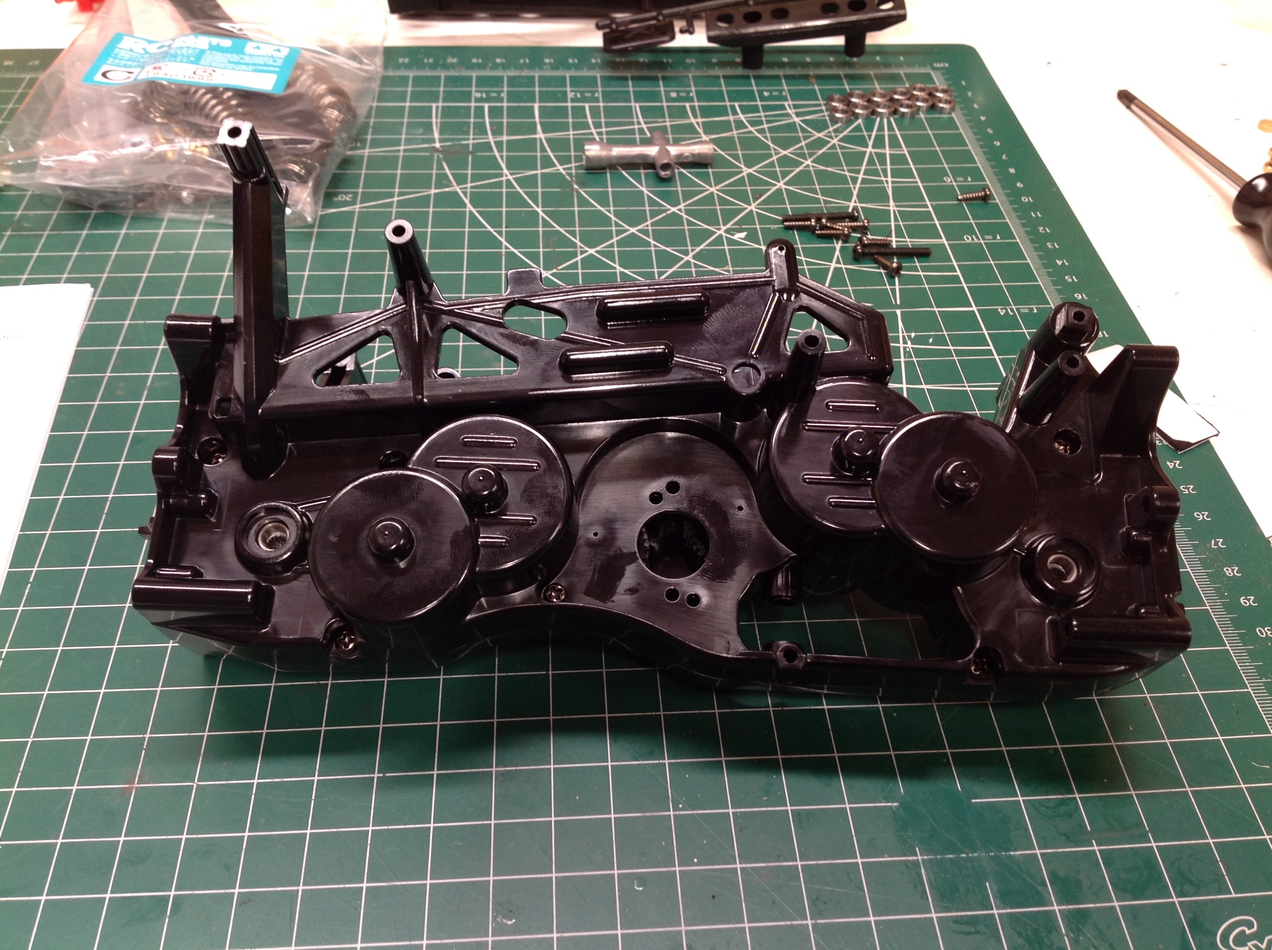
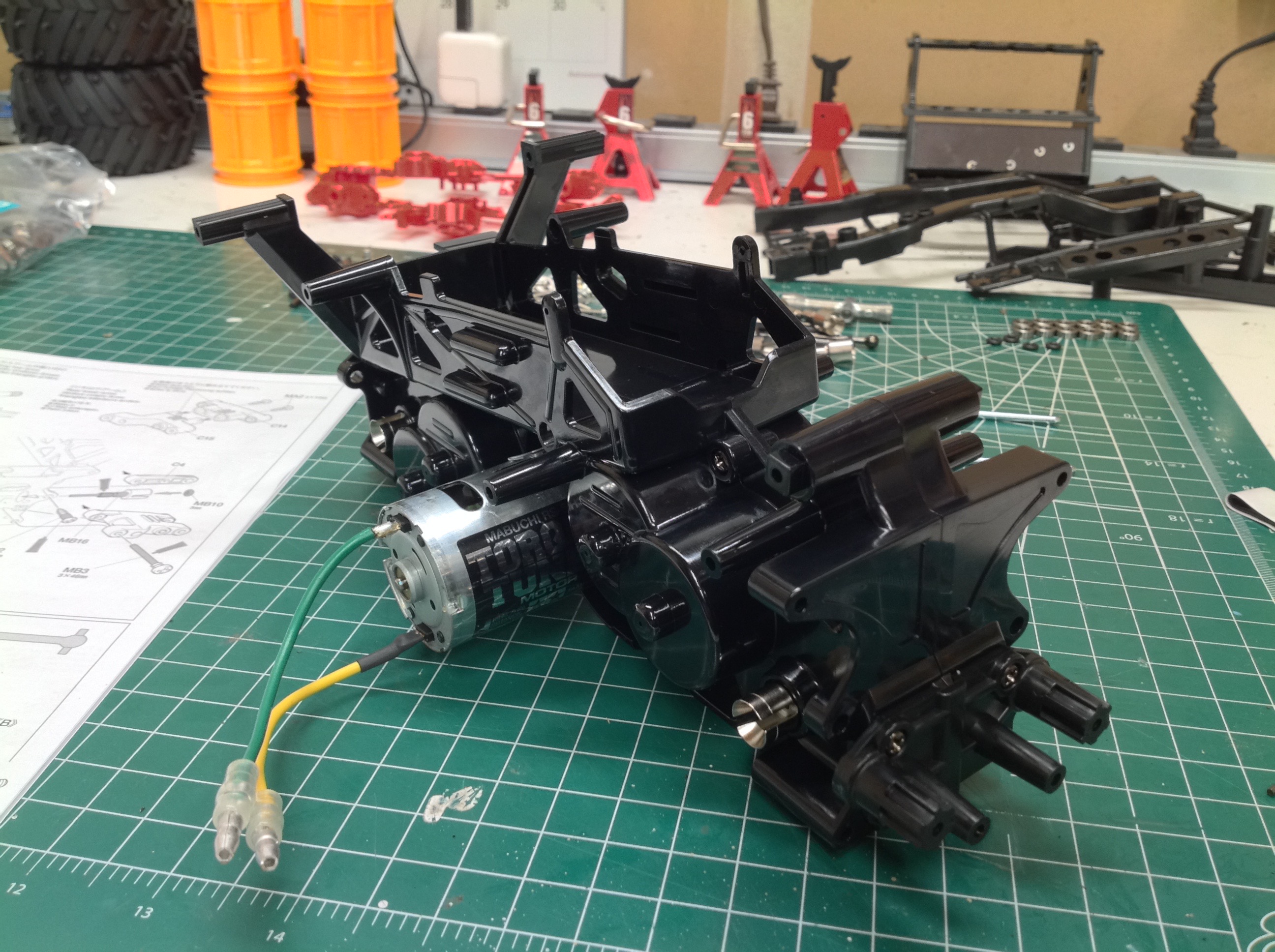
The left hand image shows two sets of mounting holes for the motor which
allow either an 18T or 20T pinion. The kits comes with the lower
speed aluminum 18T pinion which I replaced with a steel variant.
The pinion cannot be adjusted in
the usual manner by moving radially away from the mating spur, so
instead the second set of holes move the motor slightly down. The
installed Torque Tuned motor is shown on the right.
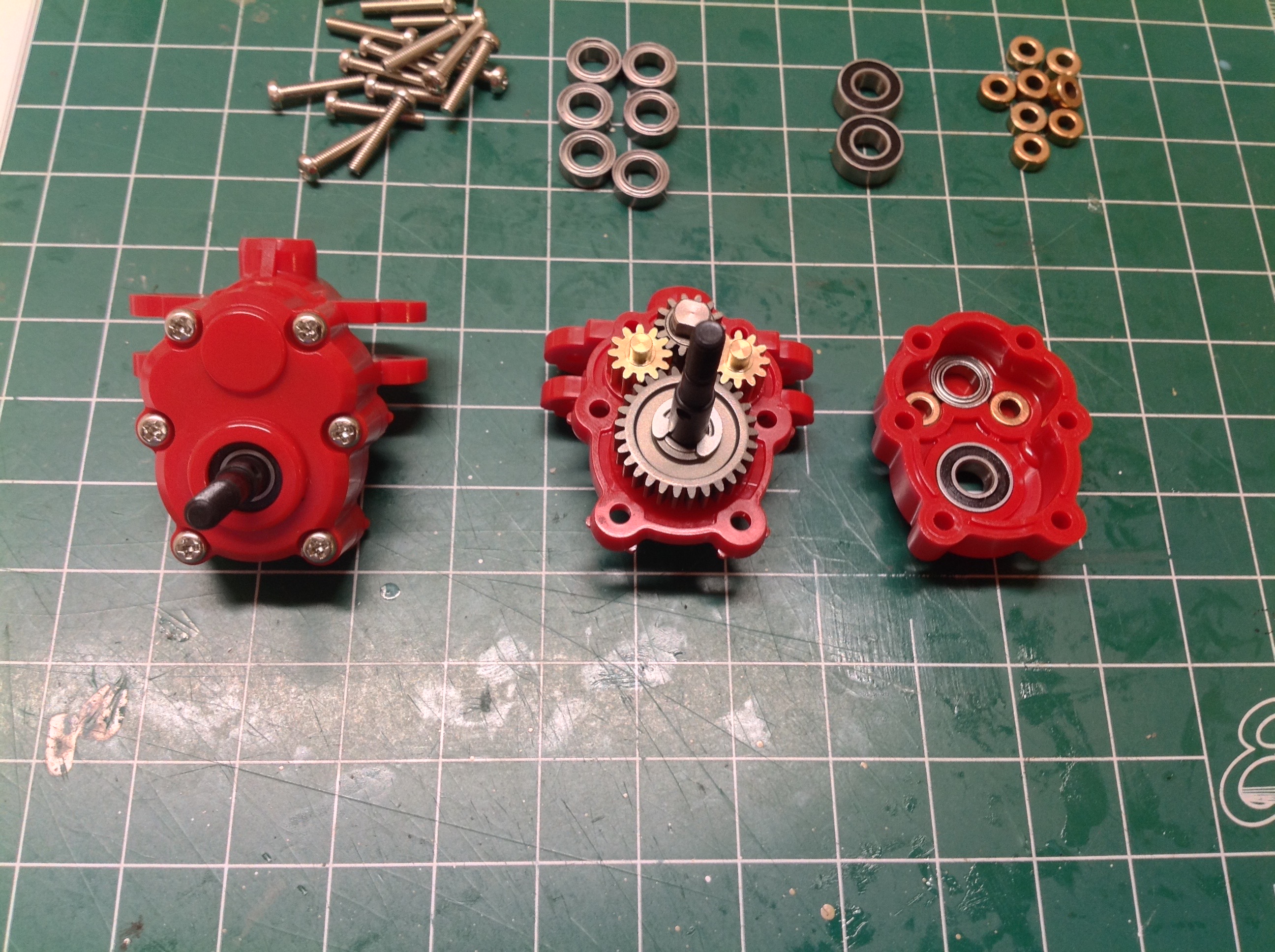
These portal axle hubs have a LOT of parts. The input and output
gears are steel while the pair of parallel idler gears are brass.
Brass is certainly less strong, but the use of double gears largely
mitigates that issue. I assume brass was chosen so that there
wouldn't be a steel on steel gear mesh which is subject to galling (and
noisy). The softer brass should be where the wear occurs. My
bearing kit did not come with ball bearings for the tiny 6x3mm metal
bushings which support the brass gears. I considered buying some
separately but decided against it. The balls in bearings this
small would be so tiny that they would not support much load. In
addition, spinning the brass axle on a bronze bushing inside a greased
housing should actually be pretty smooth. This is also the lowest
speed portion of the gear train where friction is least
detrimental. The far right image shows a metal shielded ball
bearing on the input, bronze bushings on the idlers, and a rubber
shielded ball bearing on the output. The rubber shield on the
output will help keep water away from the balls.
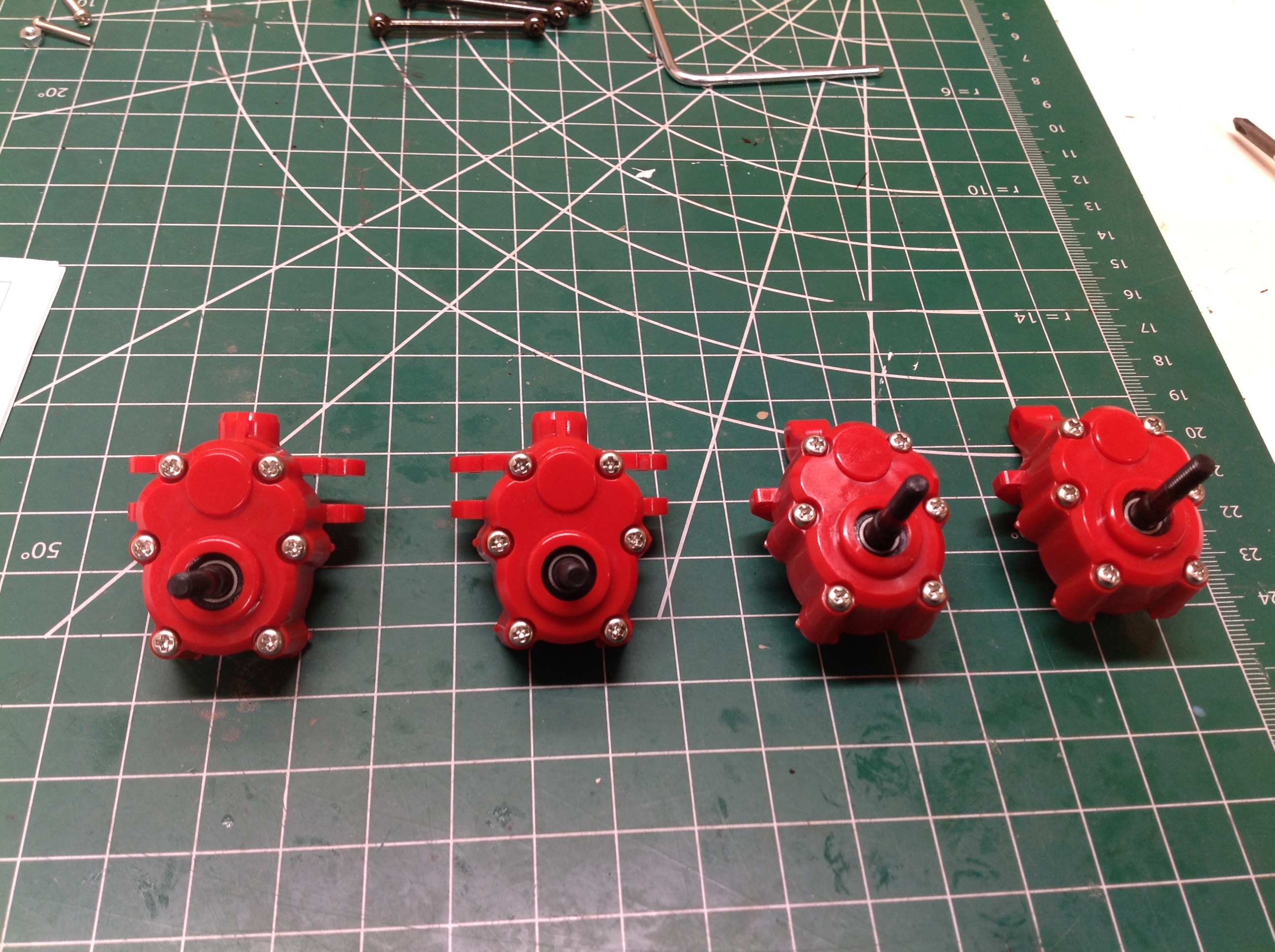
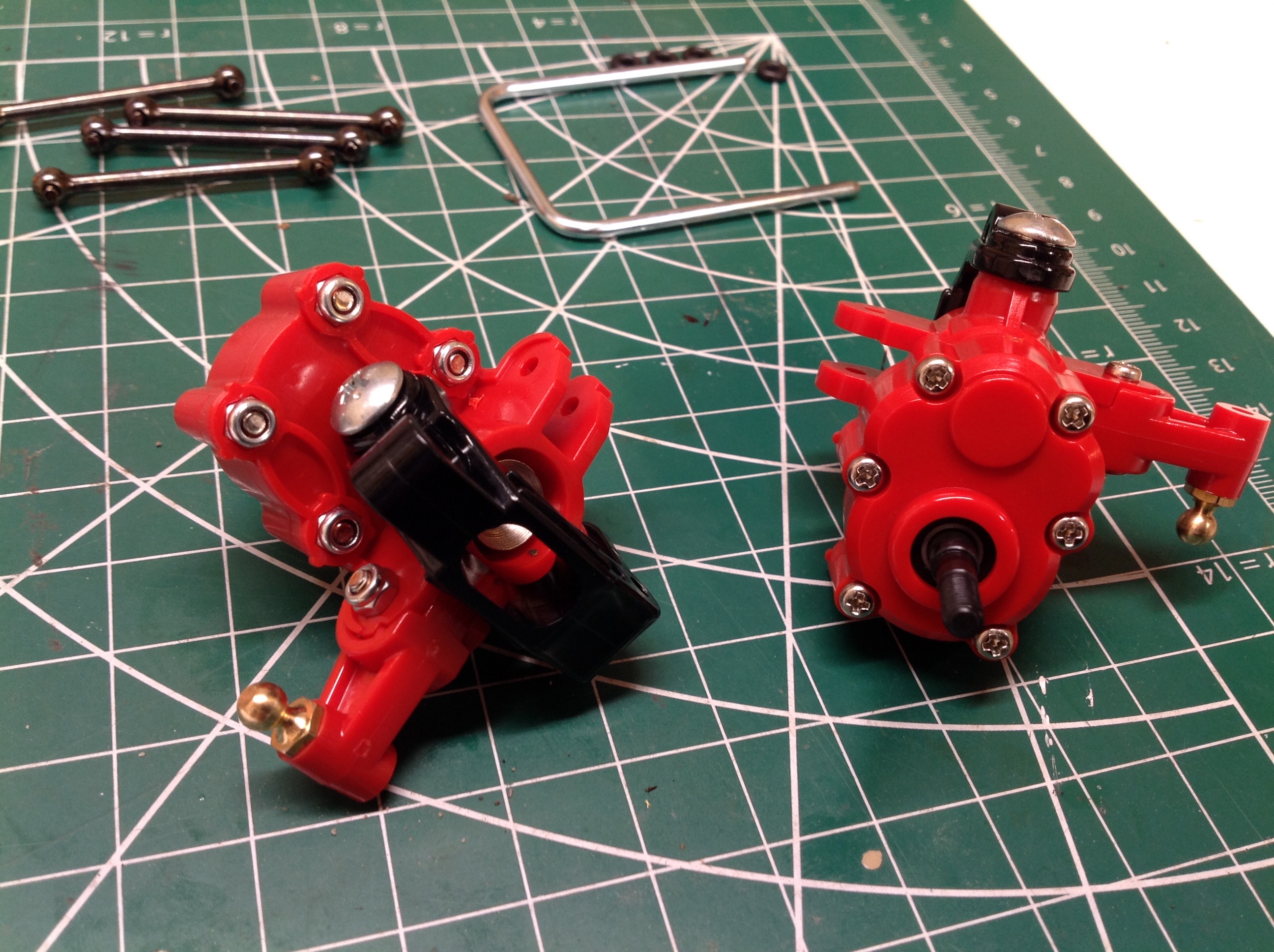
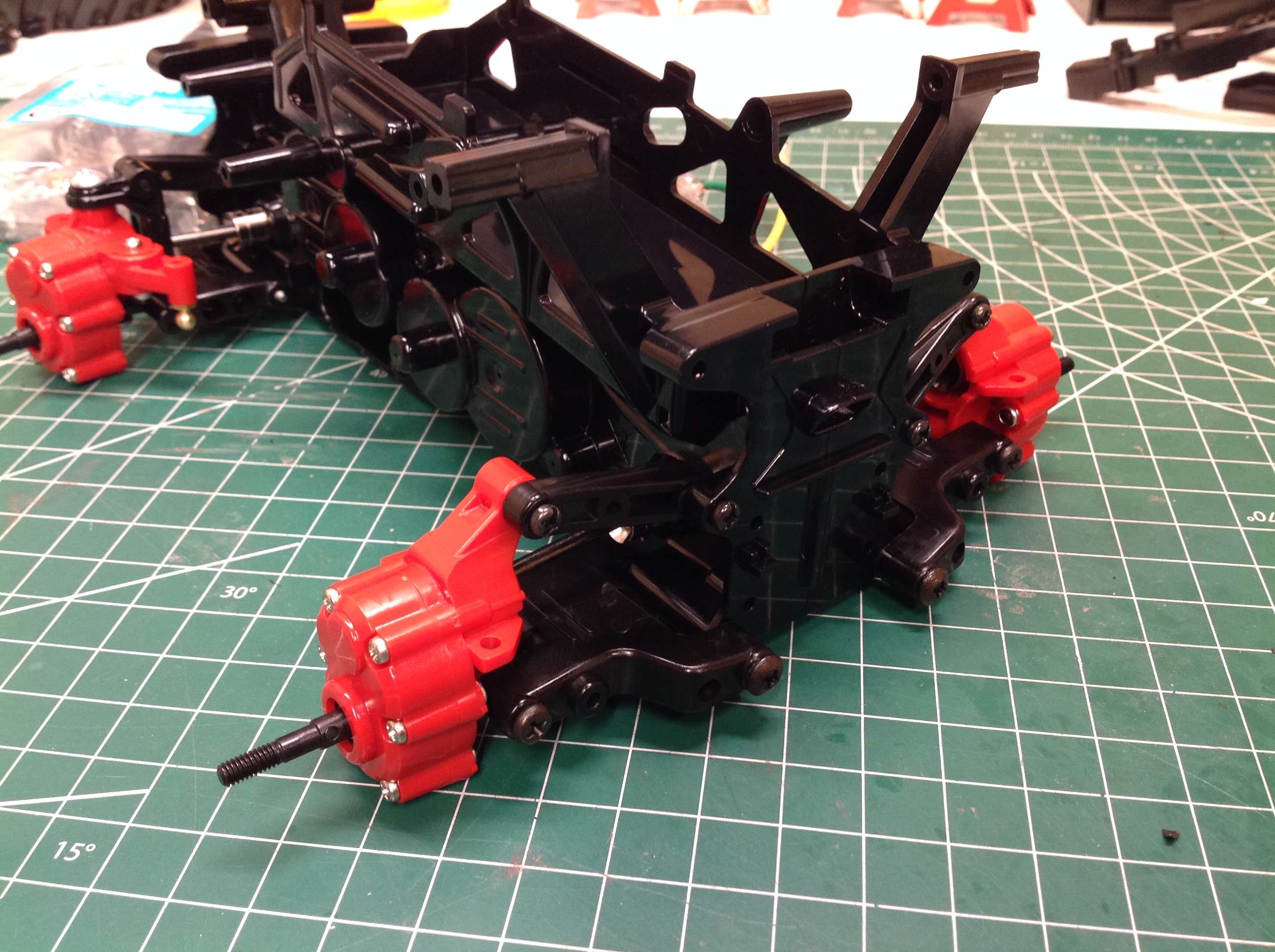
Here are the completed front and rear portal gearboxes. They
differ only in the provision for steering on the front. The left
and right steered parts are also identical, but use a mirrored steering
horn as a separate part. There are 6 screws and nuts locking each
housing. This is actually important for strength since threading
directly into the ABS would not hold as well. The model uses drive
cups and dog bones for torque transmission to the hubs.
Here the portal hubs have been installed to the independent
suspension. The lower control arms are wishbones (A-arms) and the
upper arms are fixed length links.
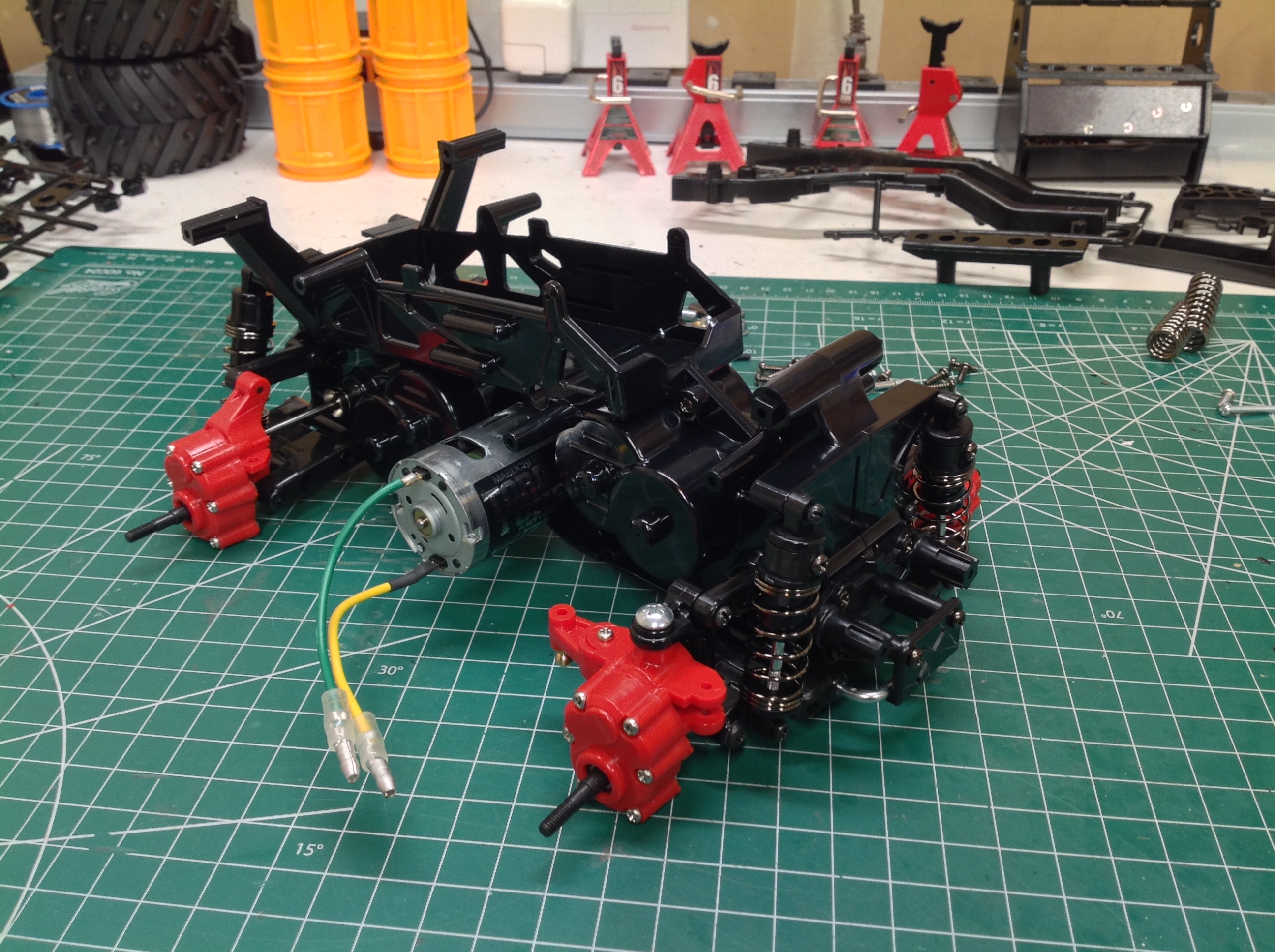
Regular readers will know that I detest friction dampers. The pure
pogo sticks are the worst, but this model at least has some rubber
tubing inside the shocks to provide some damping. Oddly, I don't
hate them. Something about the combination of this model's speed
and the compliance of the balloon tires makes for acceptable
performance. It is theoretically possible that I won't replace
them.
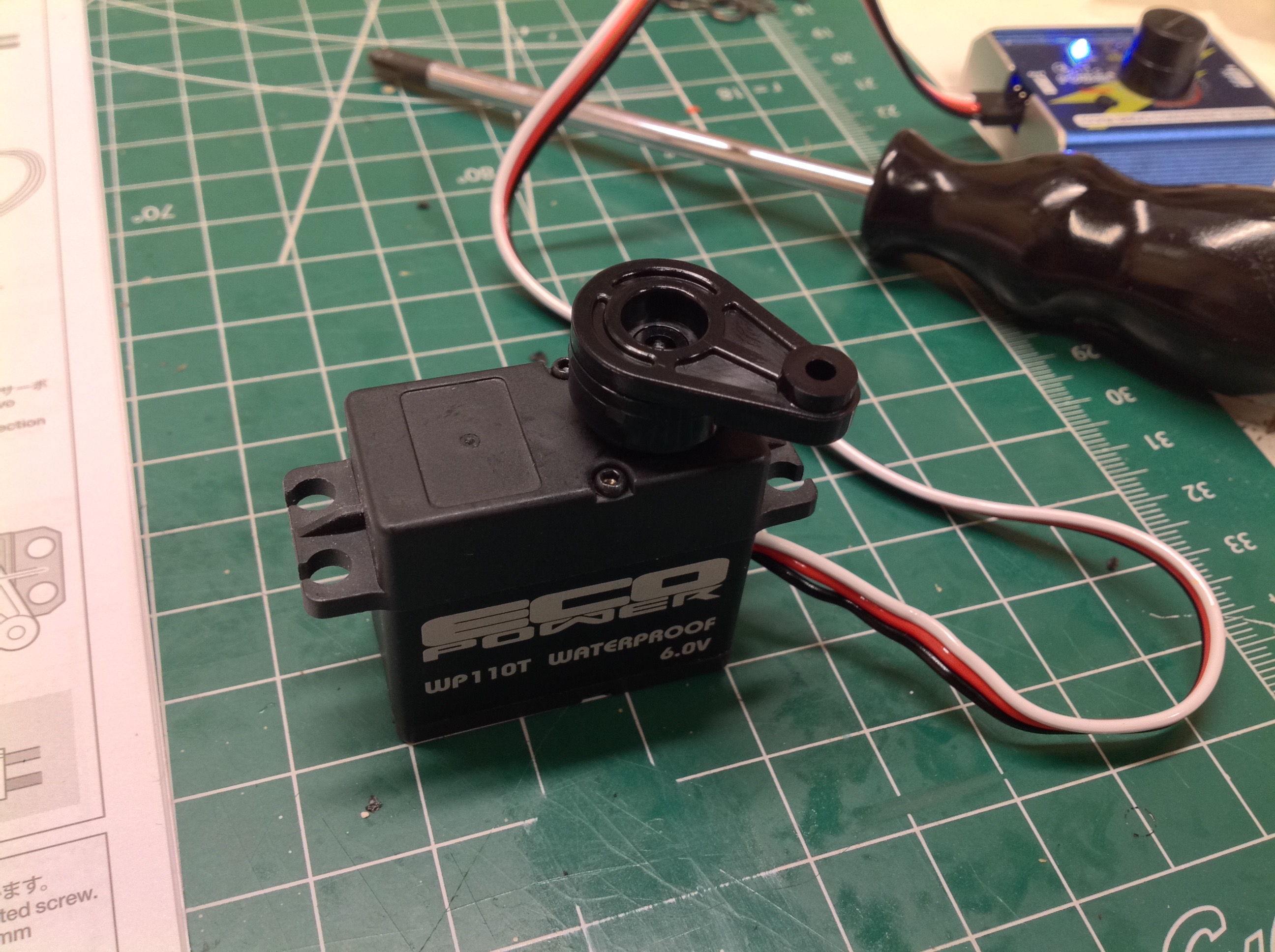
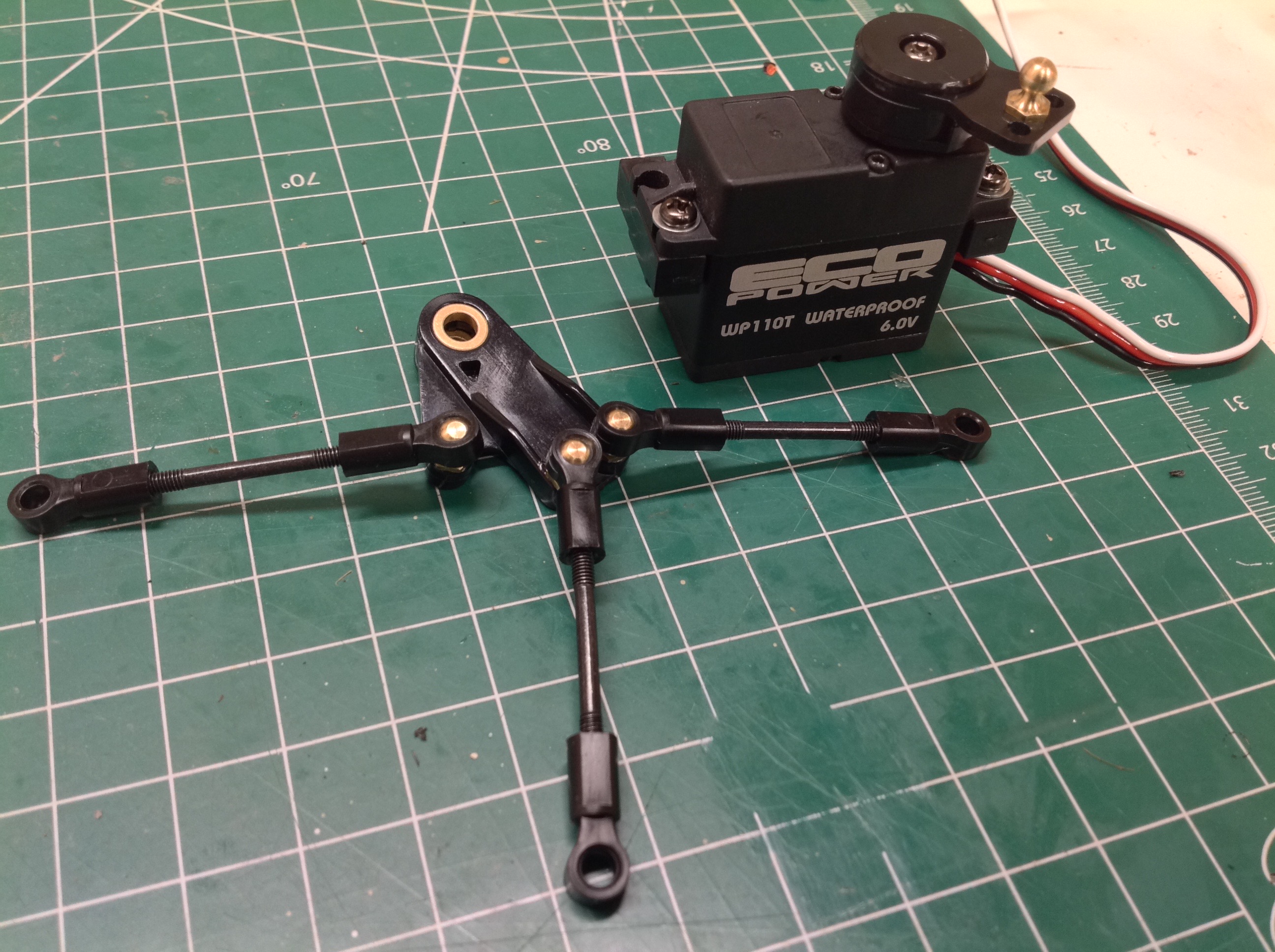
I figured that with large tires and the potential to drive in some
semi-serious off road conditions, I should use a moderately powerful
steering servo. I chose a waterproof 110T from Eco Power with
280oz-in of torque. The steering system is strange. The
servo horn attaches so it is at 45° when the servo is at neutral.
Another funny little chicken foot crank, shown on the left, will
transfer the motion to the front knuckles.
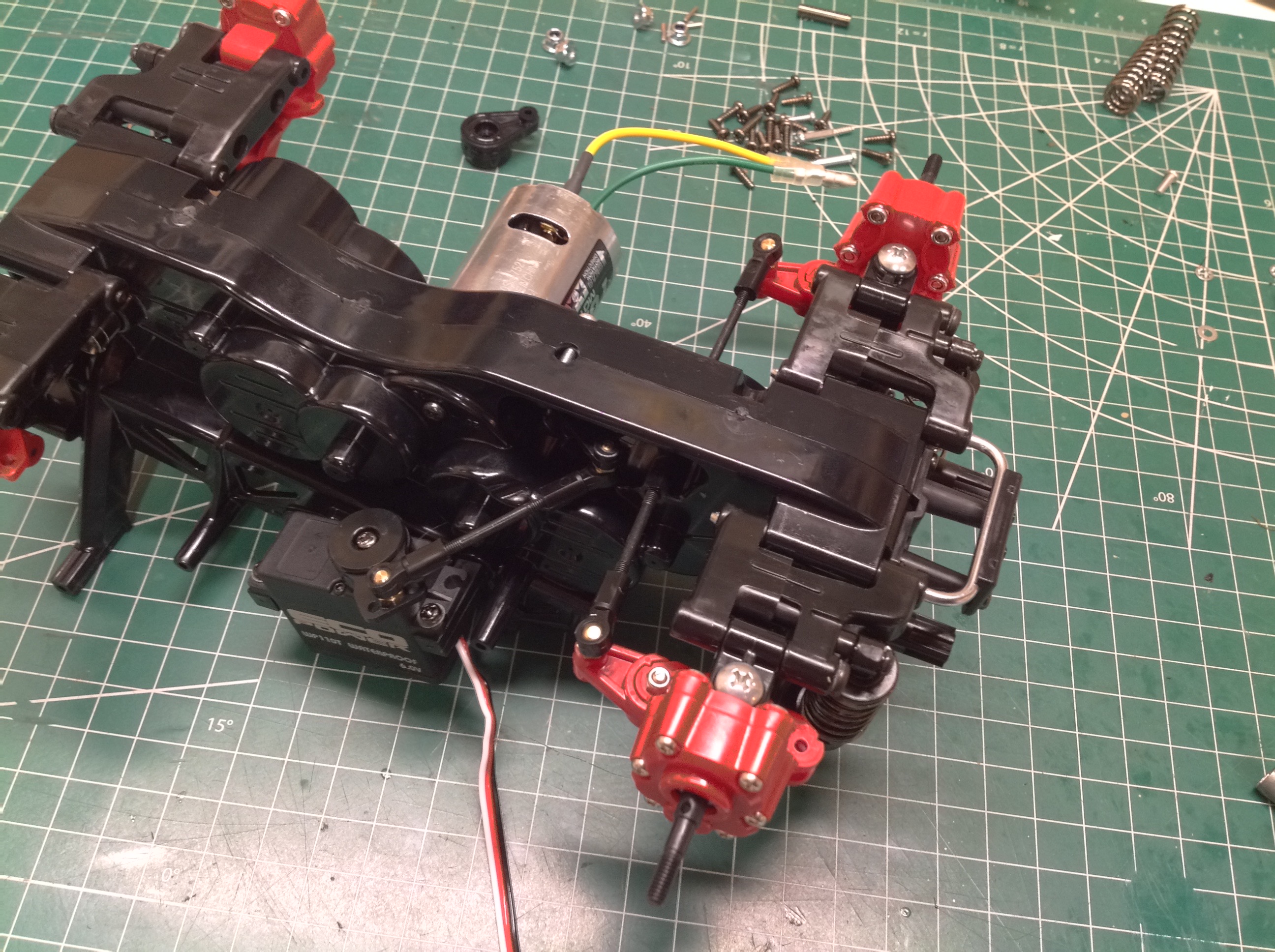
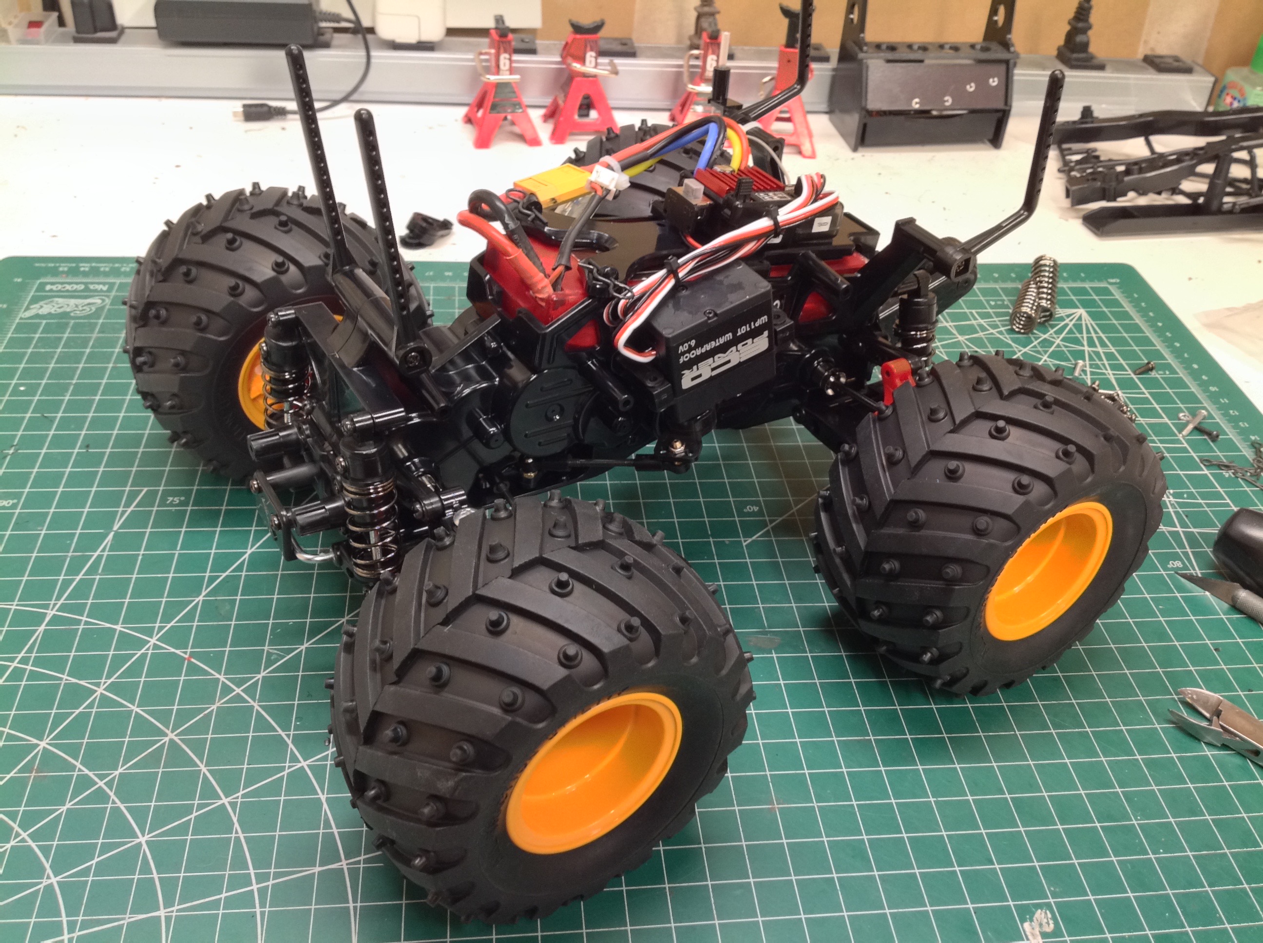
The bottom view on the left shows how the steering works. Since
the chassis is a solid block of gears, the servo can't be installed in
the center. It is hanging off one side and inverted as
shown. A diagonal link connects to the chicken foot which sits in a
slot in the chassis. It looks strange but works rather
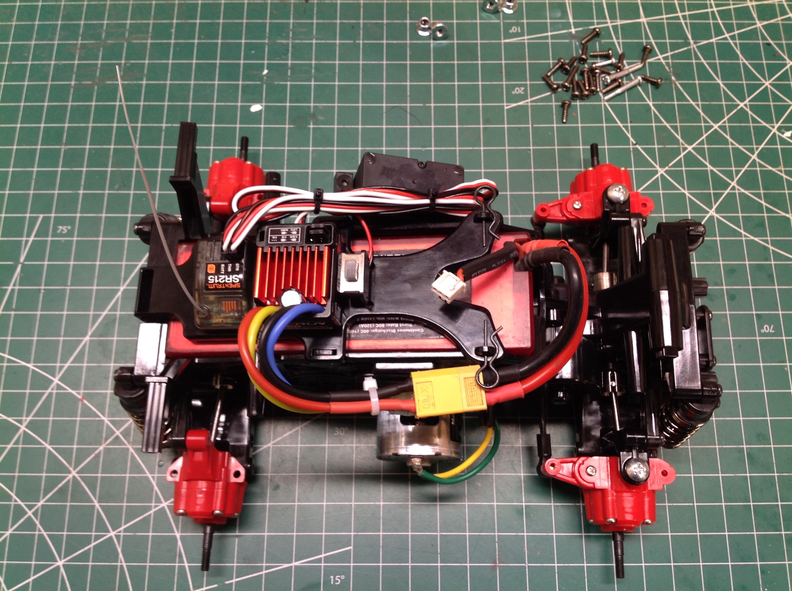
well. The top view on the right shows all the electronics
installed. The ESC and receiver sit on top of the battery
cover. The battery compartment fits a standard size rectangular
hard pack.
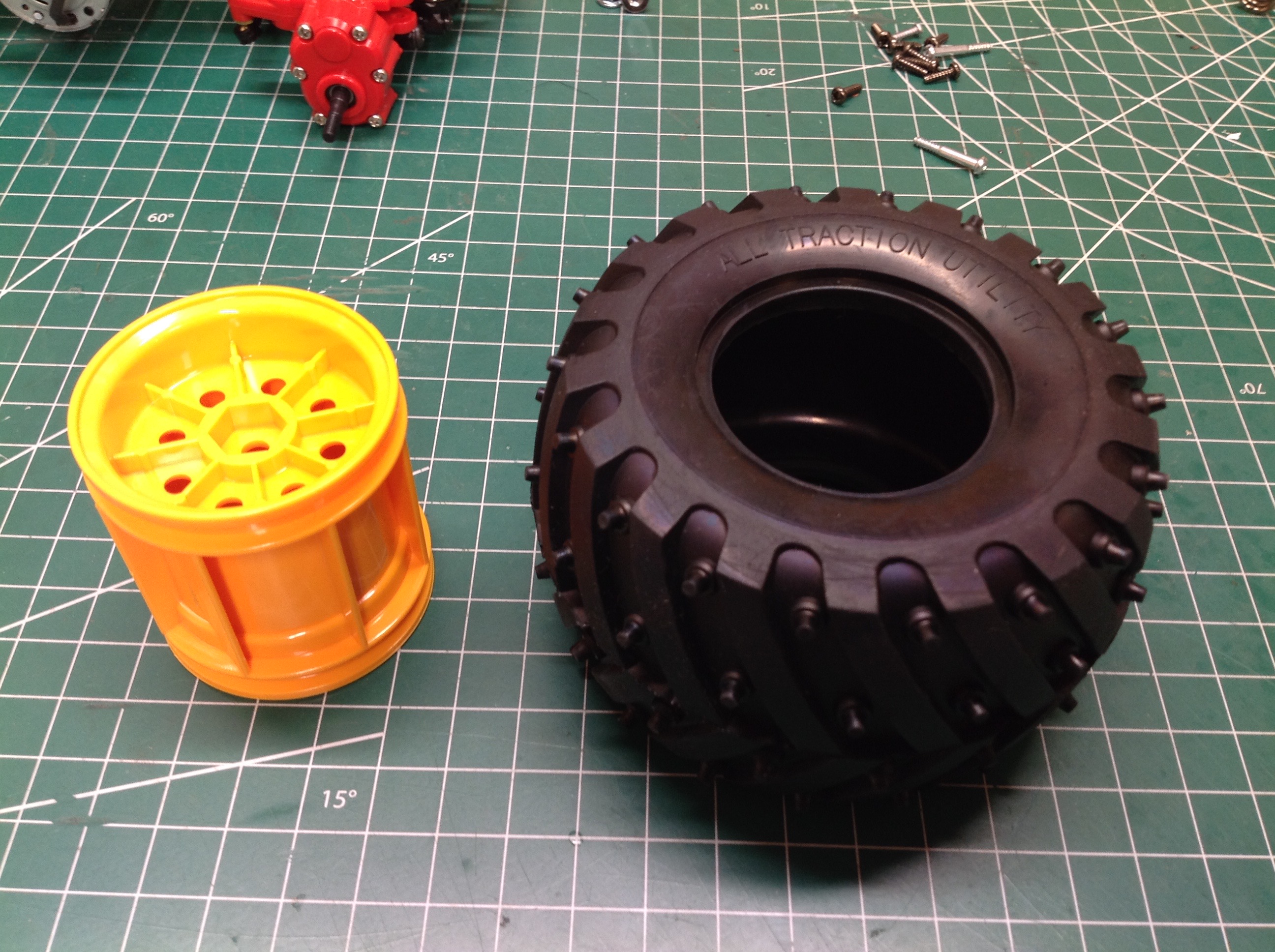
The tires use a chevron pattern with round spikes just like the tires
from the regular Monster Beetle, but they are not the same size.
They are smaller in diameter, but wider. These tires are not
common to any of my other models.
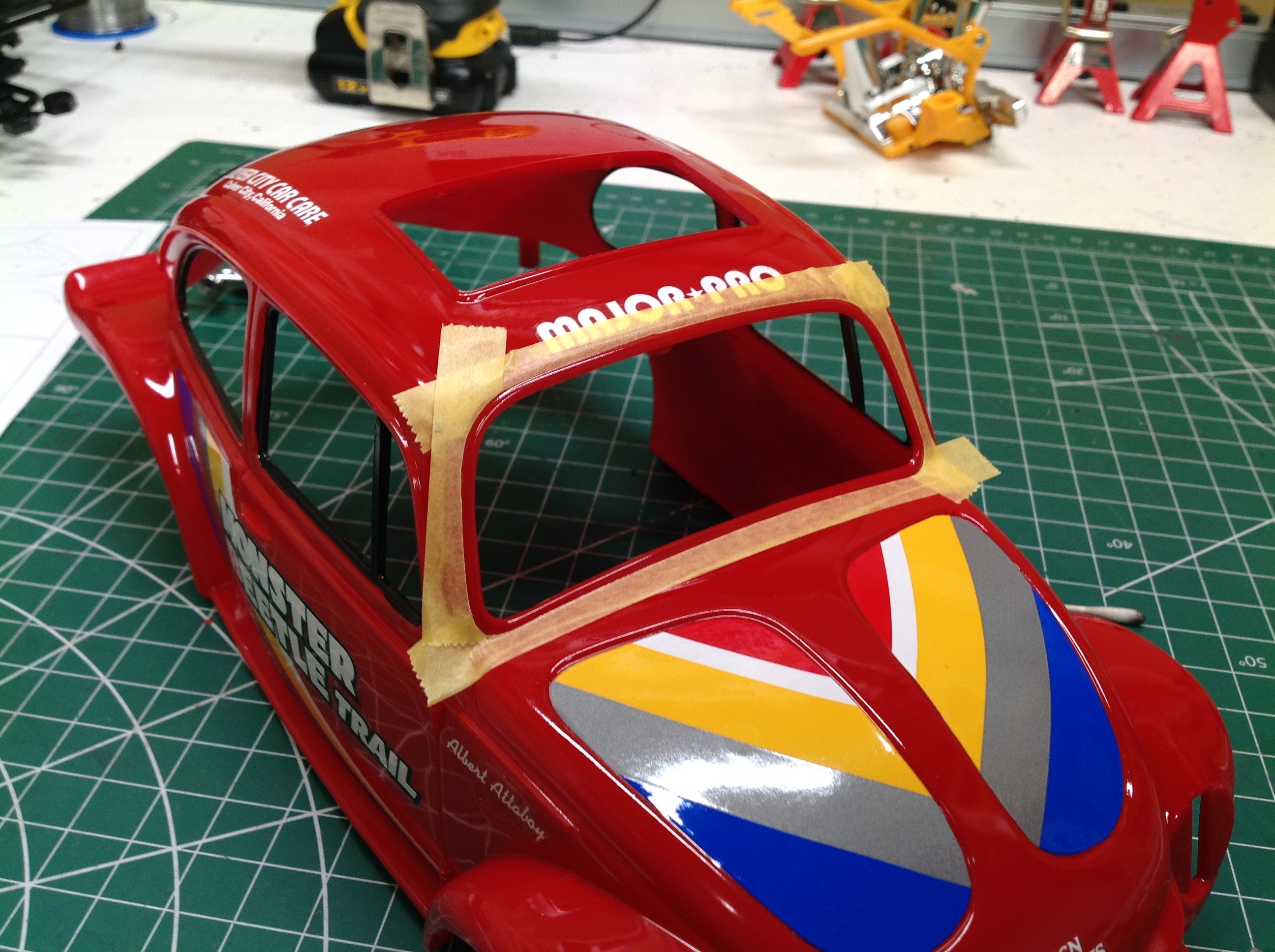
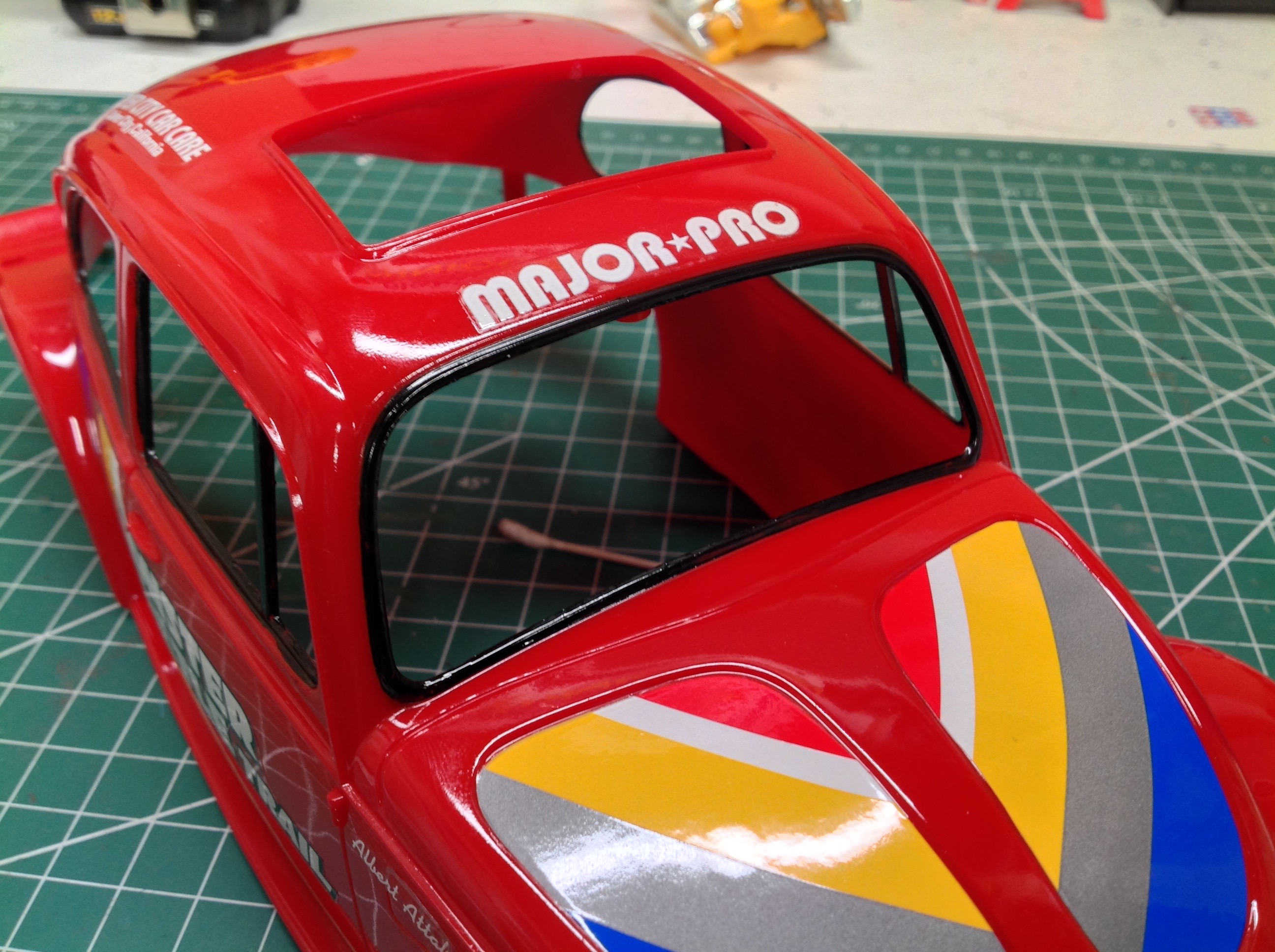
First I sprayed the body with Italian Red, then I moved on to the detail
work. The pictures above show the masking for the front window
trim followed by the result. I've also applied the stickers and a
couple coats of clear.
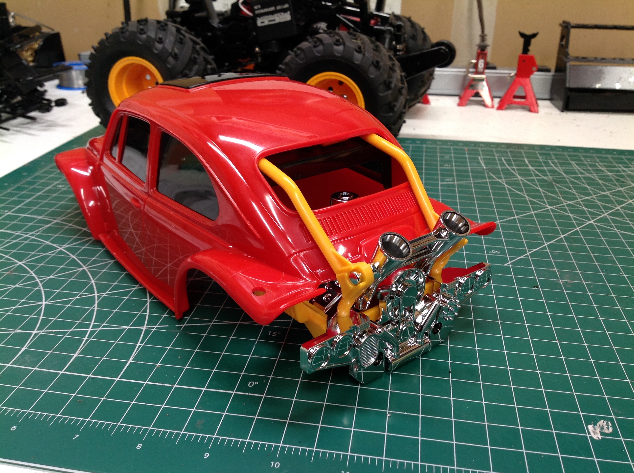
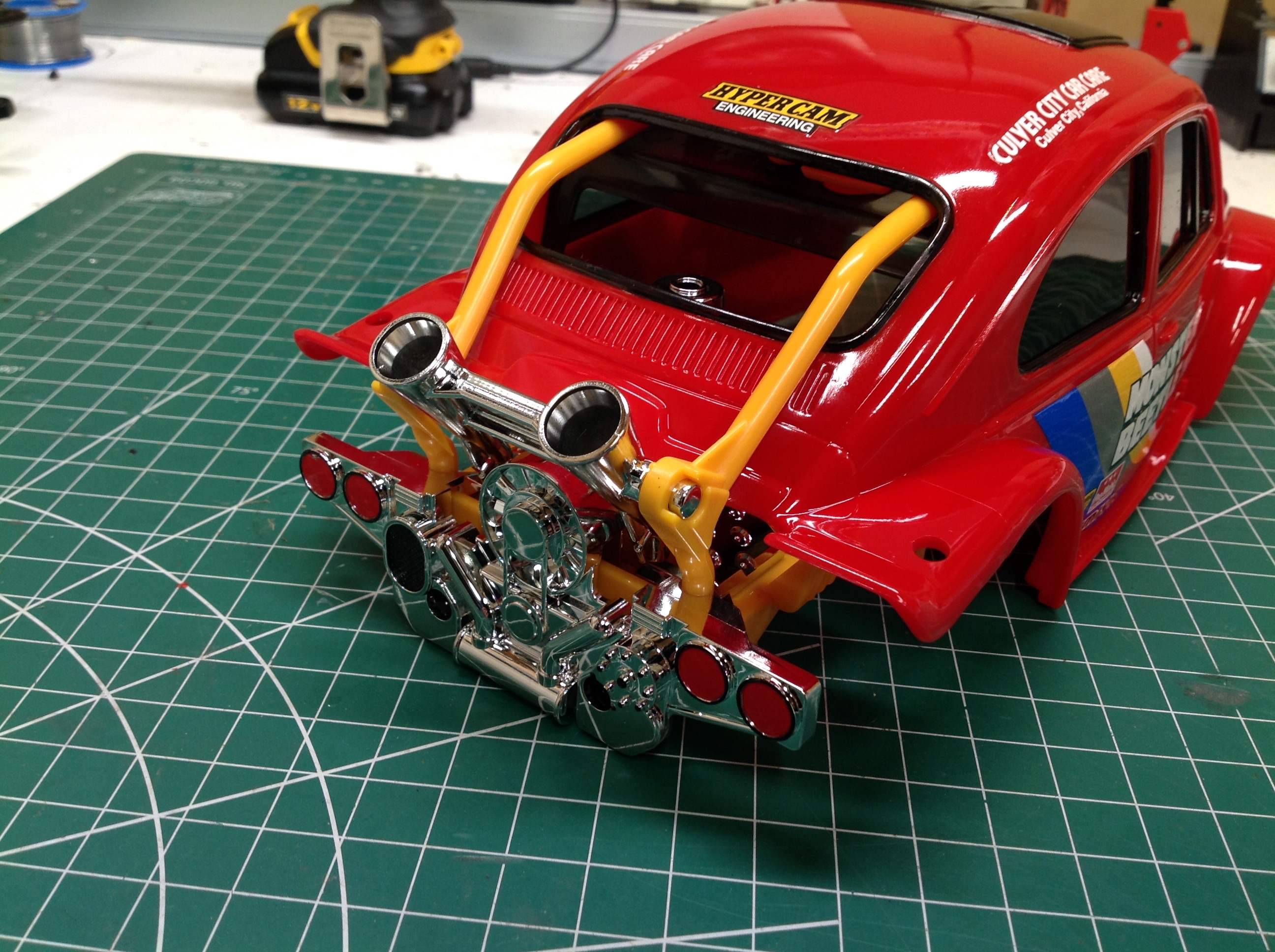
This Quick Drive Monster Beetle body includes a scale rear engine and
roll cage which protrude from the back window as shown. The chrome
engine and exhaust actually look pretty good. I also painted
black rings around the tail lights. The left picture is a test fit
before anything was painted; the right picture shows the final result.
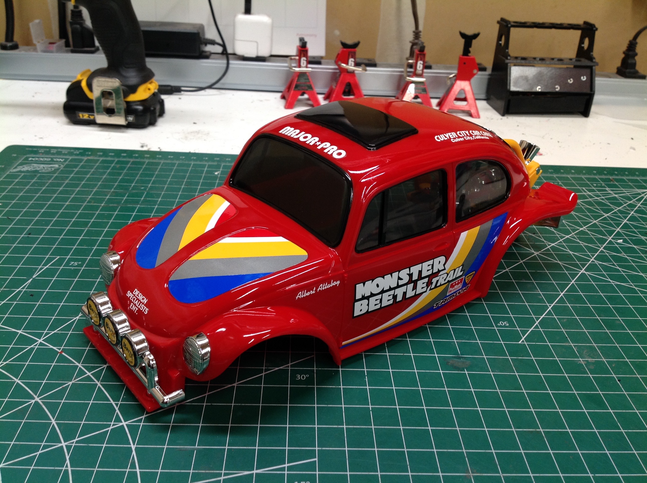
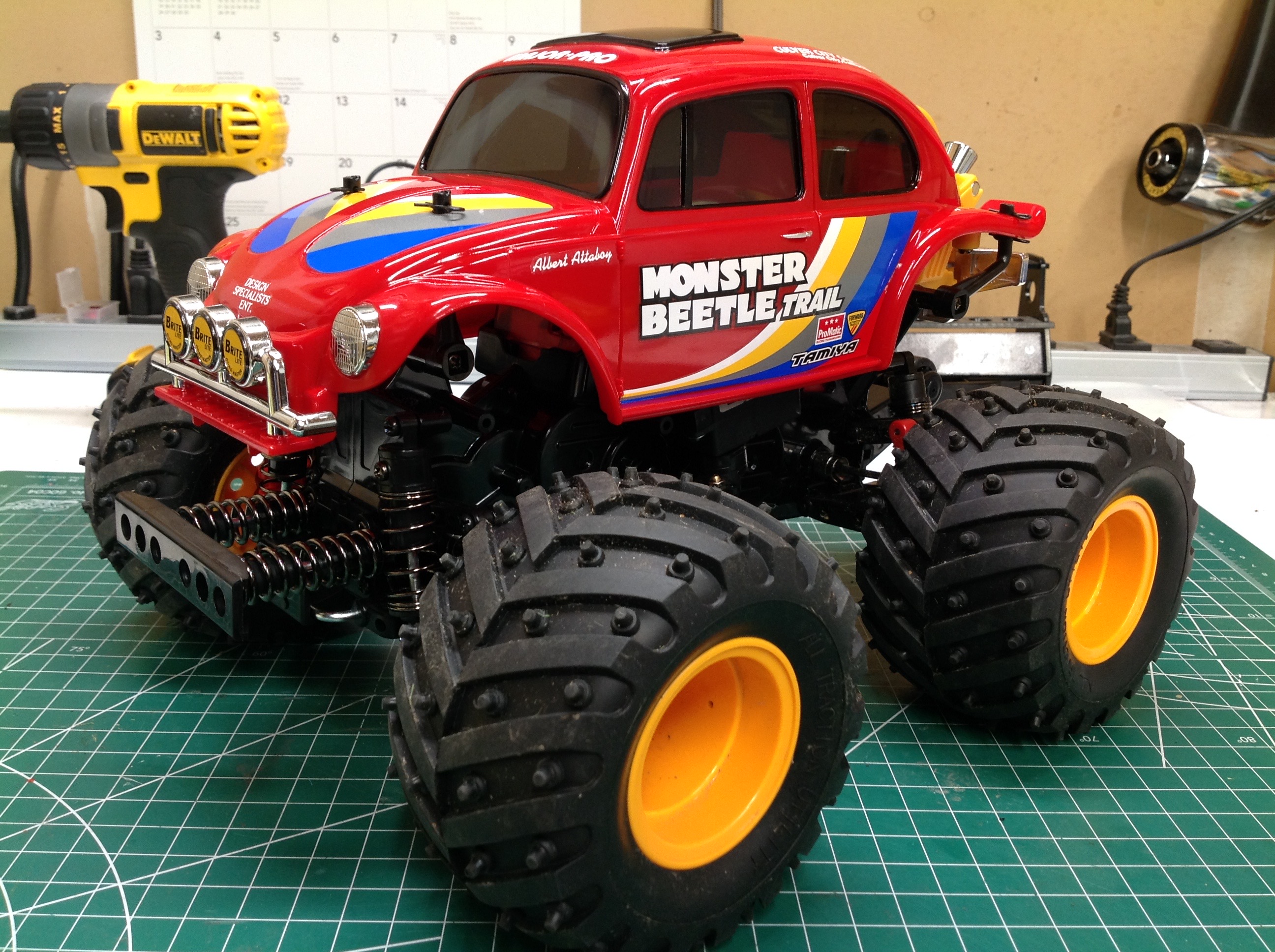
Here is the completed body with installed headlights and fog
lights. On the left the body has been installed on the chassis,
completing the model. I can't say I've ever seen a Beetle quite
like this before.
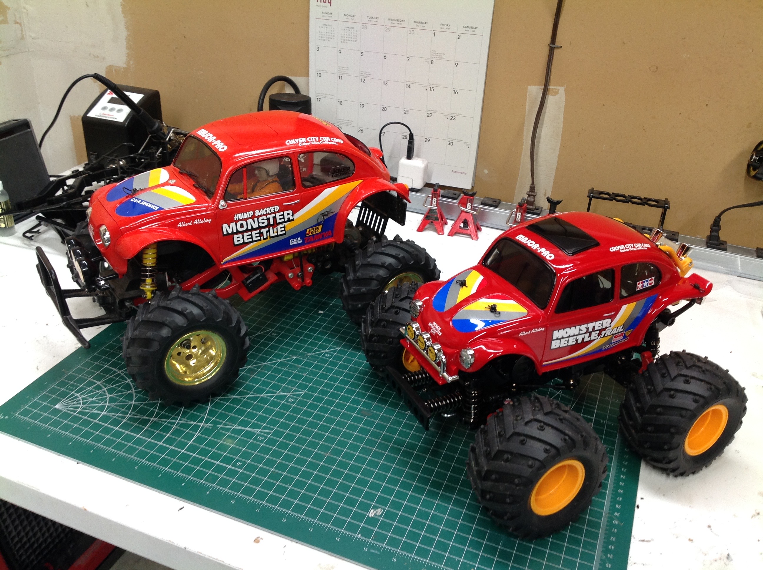
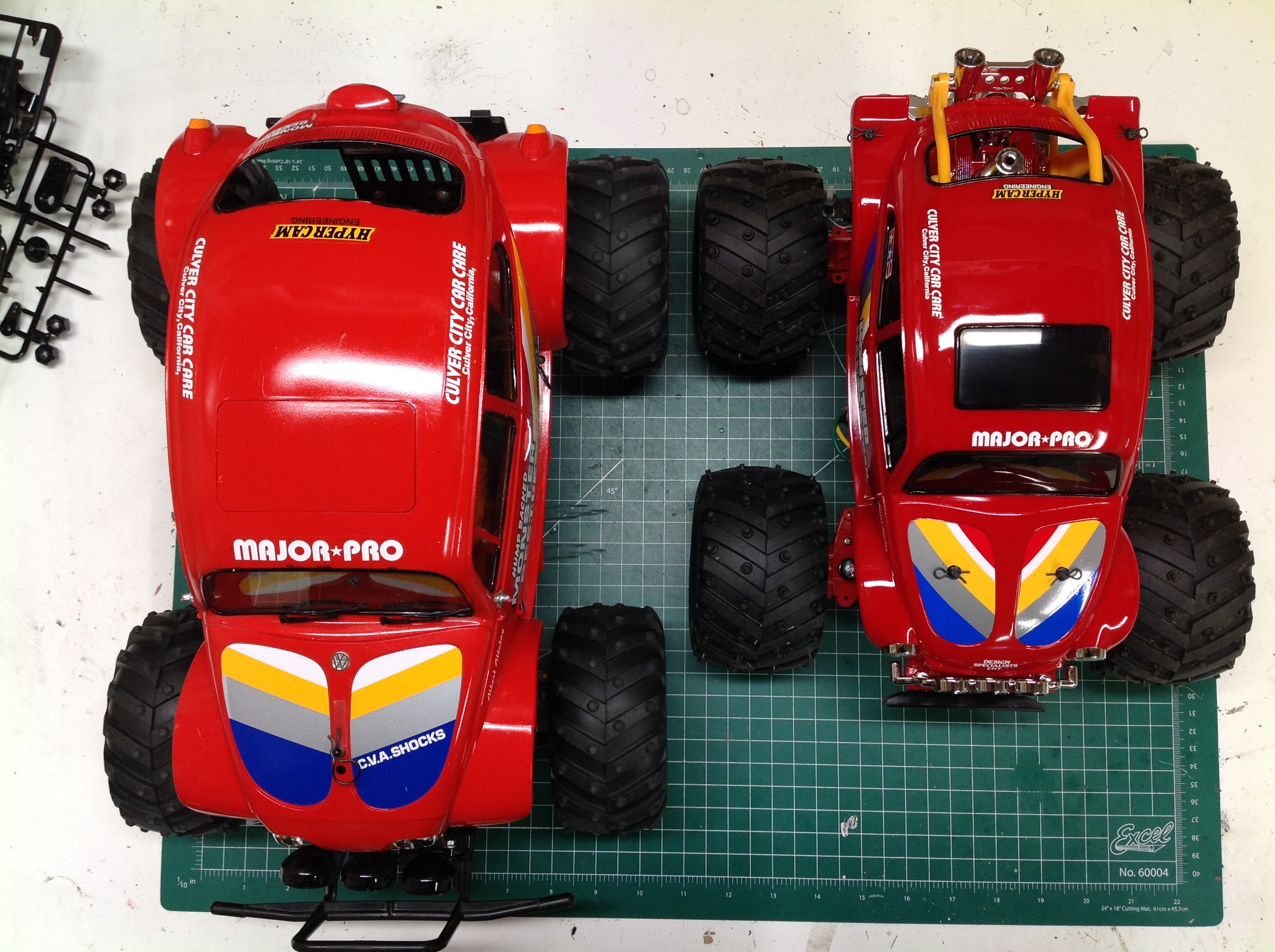
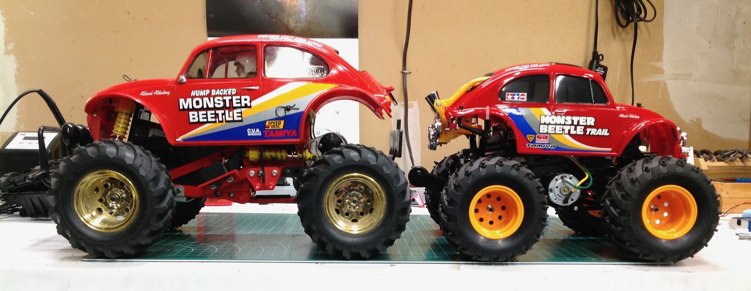
Let's look at some comparisons with the original Monster Beetle. I
used a different red for the original which makes it look a bit more
pale. The wheels are obviously different, but from a 3/4 view they
look pretty similar. From above, however, you can see how much
longer and wider the original body is.
Although the original Monster Beetle body is wider, the chassis of the
Trail makes up for it and ends up with a similar track width. The
original is also significantly taller with more ground clearance.
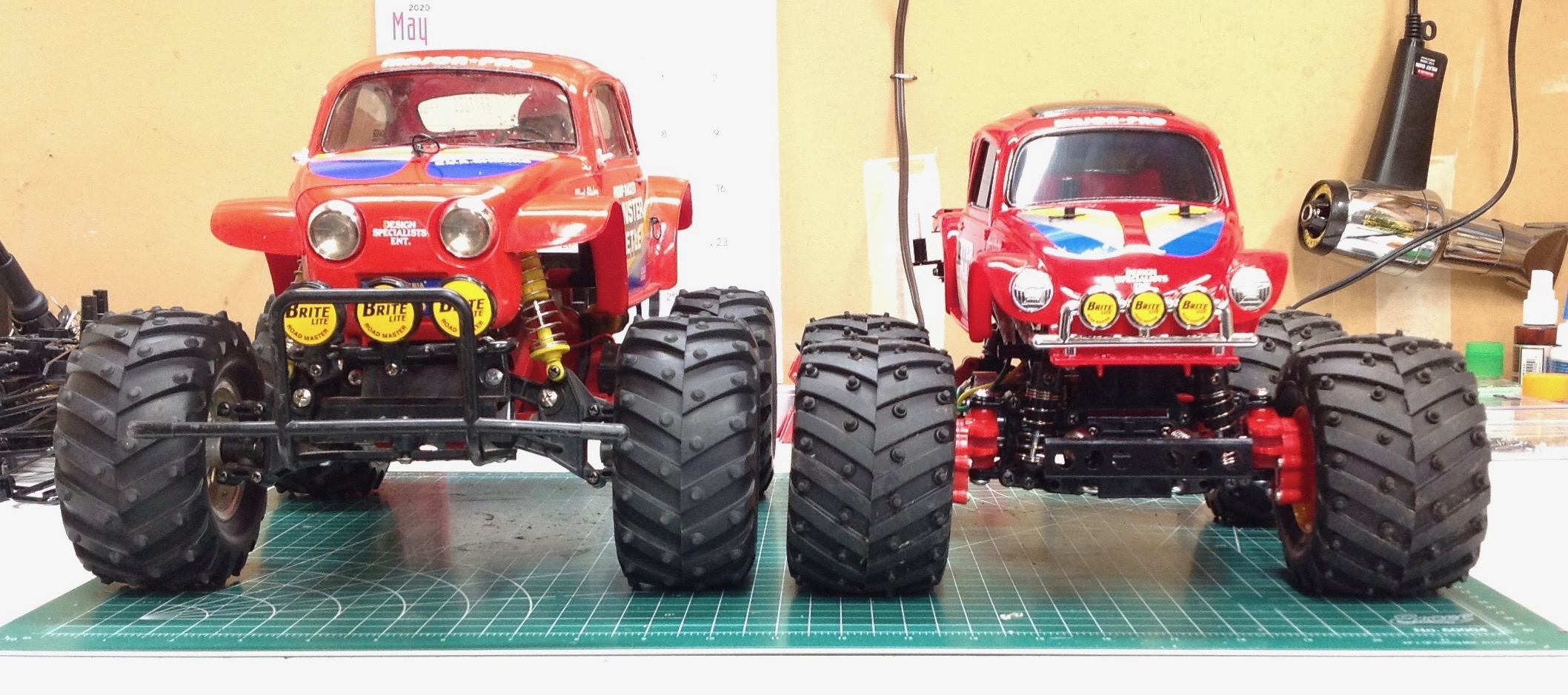
From the front you can see that these are different versions of the
Beetle. The OG uses headlights mounted to the nose while the Trail
mounts them to the front fenders. The fenders are also more
curved on the Trail.
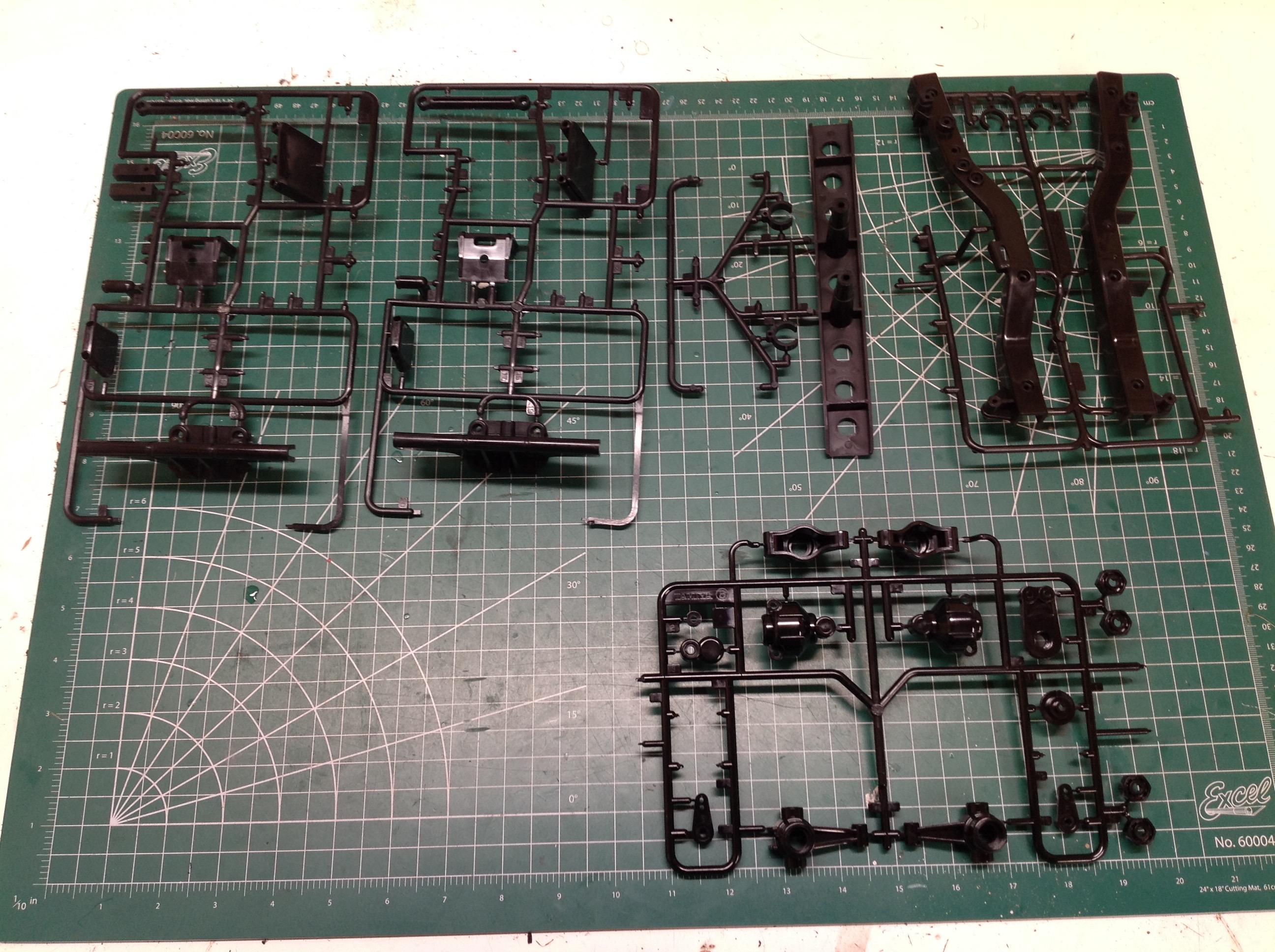
The GF-01 CB is obviously a heavily modified version of another
chassis. All of the parts shown here would have been used on a
regular version, but are just extra here. That's a lot of spare
parts, though none of them are usable for this model.
©2020 Eric Albrecht