Tamiya Leopard 2A6 Project

Page 5: Building the Turret

You might think the turret is pretty small and easy since all the drive system was in the hull, but you'd be wrong.  In fact, there is far more going on in the turret (and in much closer quarters) than in the hull.


The first thing we need to do is build the slew ring and that starts with Step 41.  We have some very rigid and durable plastic here in black.  The white part is a nylon roller cage, and each of the 10 ball bearings must be installed and greased manually.  A second black ring and a second coned roller cage are placed over the first.  One cone faces out and one faces in so the weight of the turret centers everything very well.  Finally, a ring gear screws on.  The base ring and upper ring gear will be fixed to the hull.  The center ring will hold the weight of the turret and a pinion fixed to the turret will drive against the ring gear to rotate the turret.


Step 42 installs the bottom of the turret to the slew ring and also gives you a sense of its scale.  There is an extremely small amount of clearance on the back.  In fact, at this point the turret hits the engine intakes.  Later turret components will stiffen it so it sags less and make it clear.  The slew ring is not quite axisymmetric.  There is a small index mark which must face a certain direction.  This will contact a limit switch which will prevent a declined barrel from striking the rear of the hull if you rotate the turret all the way aft.  Tamiya thought of everything.


Steps 43-46 have you check out all the radio gear, but I had already done that earlier so I just needed to attach the servo horn to the one and only servo in this complex model.  The servo was included in the kit.


Next we build this little gearbox which controls the turret rotation.  The motor uses a worm gear to drive a spur and there is one further stage of reduction.  The output is a pinion which will mate with the slew ring gear.  The pinion incorporates a ratchet mechanism which will allow it to skip instead of breaking gears if the turret is blocked.  It is pretty easy for this to happen since the barrel sticks out so far.  If you strike the barrel against an object while driving, this mechanism will save your model.  This motor is speed controlled so the driver can choose the rate of rotation.


Step 48 builds a somewhat similar worm driven mechanism for the barrel recoil motion.  The motor and gearbox assembly is used as a counterweight to balance the barrel and therefore moves with it.  This mechanism incorporates a limit switch so that you get one rotation out of a cycle.  The motor never reverses, instead the cam slot in the large gear drives a reciprocating slider which both drives the barrel and contacts the limit switch.  When the main gun is fired, the barrel recoils, returns, and shuts down.  This is not geared down much because you want the motion to be very rapid.  The cam is shaped in such a way that the recoil with will be very rapid but the return will be more gradual.  Of course this could all be done electronically in the controller, but this way all the controller has to do is give full power to the motor and the entire cycle is handled mechanically.  Clever.  The spring you see in the right hand image keeps the barrel in the outer position until the motor activates the recoil cycle.


Here the barrel elevation servo is installed.  Use of a servo allows easy and powerful positioning at any angle.  The barrel can range from +20 to -9 degrees just like the real thing.  The other wire you see is for the turret rotation limit switch.


Once you start putting these mechanisms into the turret it doesn't look so spacious and tidy anymore.  Here I've installed the gun elevation servo and the turret rotation motor.


Step 51 begins construction of the main barrel assembly.  This is the root of the barrel and the top armor plating.  The wires are for an LED which imitates the muzzle flash of the coaxial MG3A1 machine gun.  Both the machine gun and the main gun can be fired from the transmitter.


Now the aluminum main barrel tube is attached to some accessory parts.  The tip at the end of the barrel is made from transparent acrylic.  I was not sure why this was done given that it must be painted, but I found out later.  The Leopard 2 has a 120mm smoothbore gun, no rifling.


If you thought the barrel would be simple, here is where it gets really complicated.  Here at the back of the barrel in Step 53 we install the recoil motor along with its limit switch.  We also pass through an odd looking little orange taped tube.  It turns out this is a Zenon high voltage bulb which rests at the mouth of the barrel.  When you fire the main gun, the high voltage unit releases its charge into the Xenon bulb and produces a brilliant bright flash which can be seen through the paint on the edge of the barrel, even from far away.  The effect is quite convincing.  They went a long way and added a lot of electronics to make this possible.  Of course the barrel also recoils when fired.  Not only that, but the entire tank recoils slightly by driving the tracks backward a tiny bit.  After firing, the barrel moves to almost level for reload and then returns to its former position, whatever that was.  The effort put into scale firing kinematic motion is stunning.


Now the barrel is installed into the counterweight mechanism and all the wires are routed and clamped so they won't interfere with motion later.  Having the barrel balanced about it's elevation axis is important because that means it won't bounce around while you drive over bumps and obstacles.


The barrel swivels about a pair of trunnions which are installed in Step 55.  Things are starting to get pretty messy up there, but is also starting to look like a tank.


In Steps 56 and 57 the DMD (Dual Motor Drive) control unit is installed and all the wires are connected and carefully routed and cleaned up.  This careful routing is not just for those with OCD, you have to route the wire this way or there simply won't be room to install the cover or for the internal motions to occur unimpeded.  You can see the controller, the wires from the hull, the receiver, the servo, the recoil motor, the rotation motor, the HV unit, and lots of wires.  Untangling them and making them neat took the better part of an hour.  The second photo shows the battery consuming whatever is left of the internal space.


Now some sharply angled armor plates are installed to either side of the gun which allows us to tuck some wires underneath.  The armor is angled this way to help deflect the energy of incoming rounds.


Since the battery is inside the turret, we need to be able to easily remove the turret cover to access it.  The armor plates on the sides are used as convenient access panels.  Behind them, a pair of removable 1/4 turn bolts lock the cover into place and then the plates hinge shut and adhere with some Velcro.  Reverse the process to remove the cover.  It only takes a few seconds.  There is also a magnetically retained access door for the DMD so you can turn the unit and on off and make setting adjustments very easily without opening the turret.


The turret cover is one big part, but it needs a few dozen little details attached to it.  Step 62 starts with the details on the underside including some brackets and windows.  If you use the optional battle system for fighting other model tanks, you'd install the receiver here.


Step 63 builds some complex little boxes.  The EMES15 Telescope is the rectangular box with clear windows and armored shutters that open and close.  The commander's panoramic site is the more cubic box and can rotate even after being installed.


The baskets on the back of the turret are used to store random crap, or so says the official German field guide.  Maybe I didn't translate it right.  The mesh is photo etched metal which means I can't use cement, I have to use CA.  CA means sticky fingerprints everywhere.  This step was hard.


Even more details for the turret in Step 65. There's a wire reel for ..... wire, I guess.  There is no wire in the kit.  We also have a periscope here and a couple of track stoppers or what others might call chocks.  All of these transparent parts will have to be masked later when I do the camo paint.


Step 66 installs all the junk built in the previous several steps onto the turret cover, giving it a lot more character.  The magnet you see toward the rear holds the DMD access cover.


The hatches are built in Step 67.  One is for the commander and the other is for someone else.  The loader.  You need to choose now whether to install the loader's hatch open or closed because it is not hinged to adjust later.  The commander's hatch is screwed down so it can be opened later which is required if you ever want to use the battle system.


Step 68 took me a couple of days and was so tedious that I forgot to take any pictures so this final picture will have to do.  All you have to do is build 16 smoke canisters.  Each one requires you to bend a single staple into the loops of a tiny 18mm chain that you have to cut to length, and then join it with 3 plastic parts.  8 of these get installed on either side of the turret.


Step 69 attaches a small metal plate to the DMD access door so that it can attach to the magnet on the turret.  The light which is misleadingly called the revolving light is used for the battle system so I didn't install it.  I also didn't need to install the old school metal antenna because a modern 2.4GHz receiver doesn't' need it.


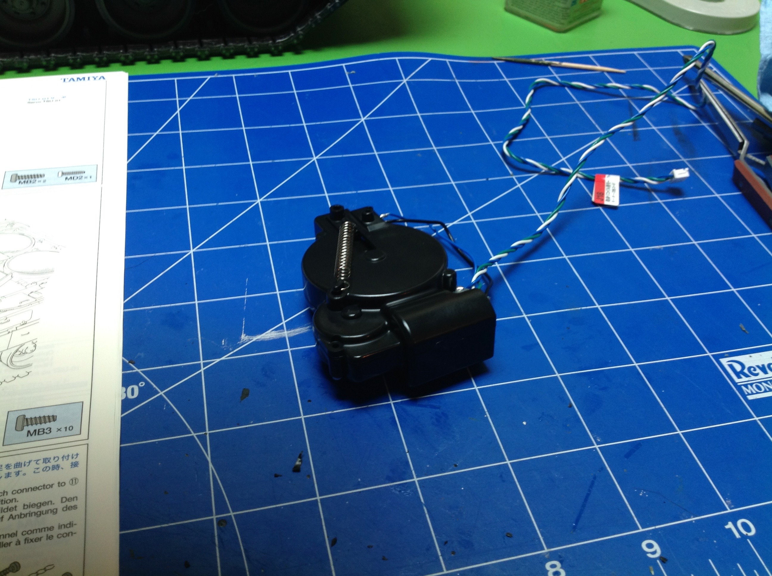
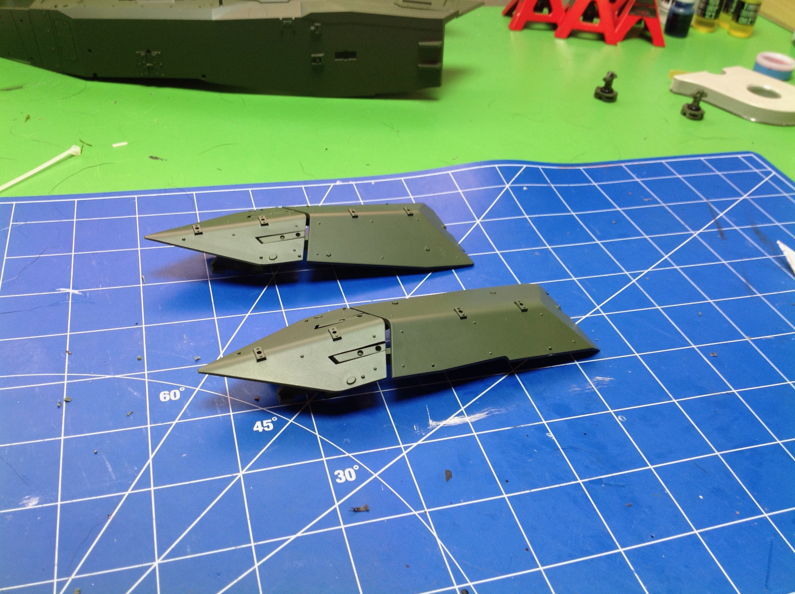
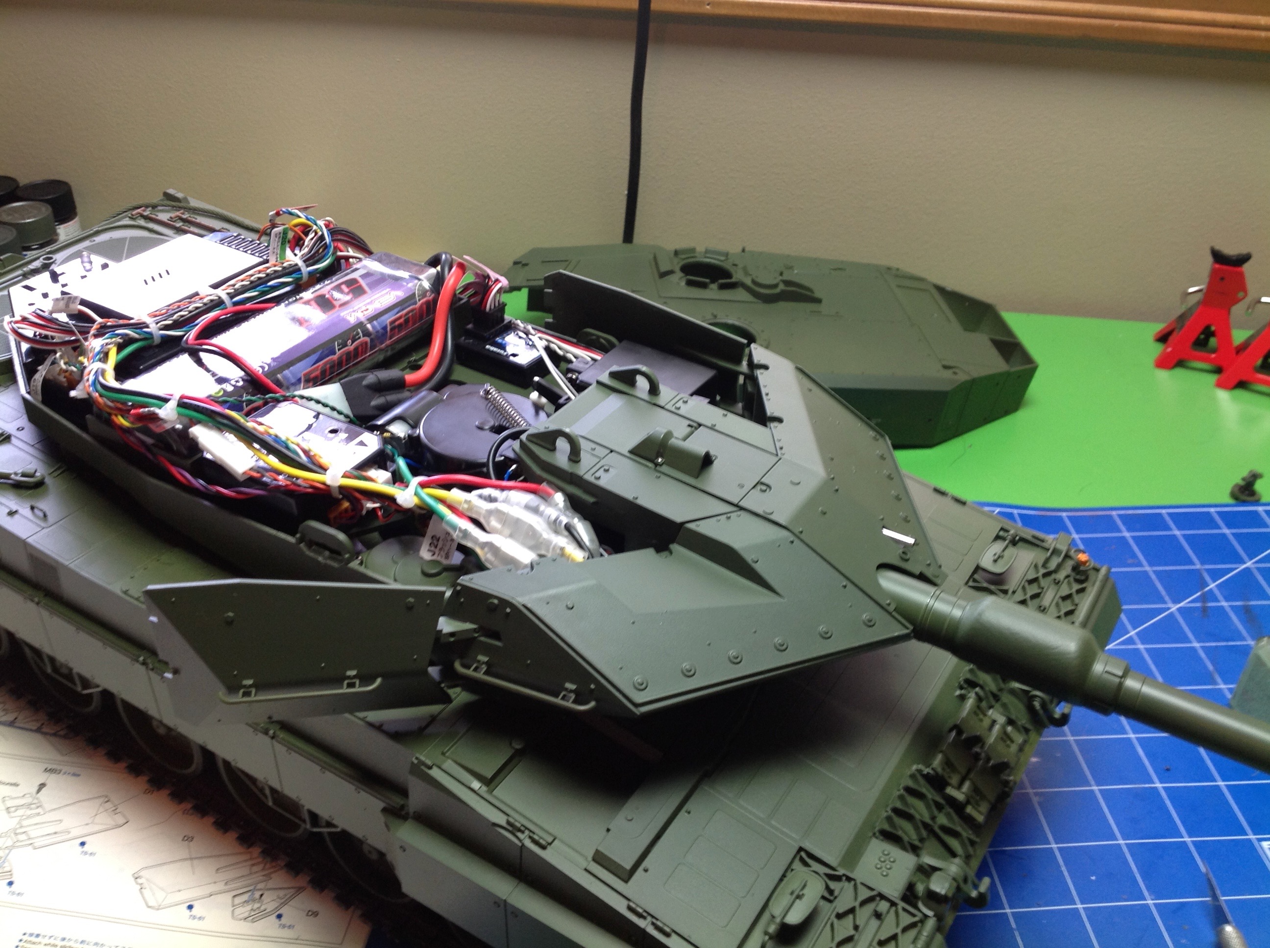
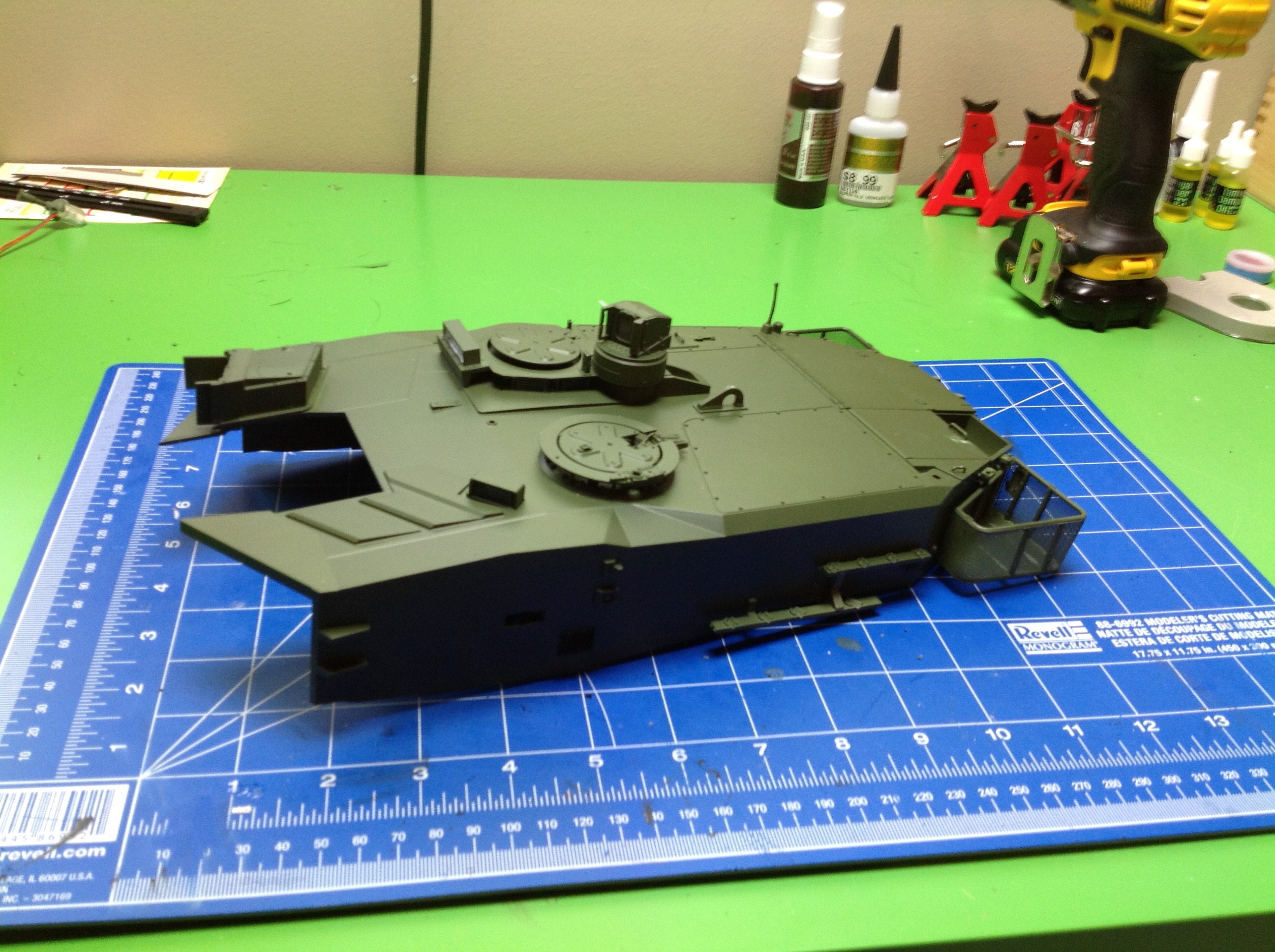
This is the last picture of the turret cover.  As usual, I got excited at this point and stopped recording my progress.  The only step left is to put this on the tank, but after that comes all the decals and the camouflage painting.  I bought an airbrush just for the task, but this was the first time I had ever used one.  I was VERY worried about screwing up all my beautiful work, so I took several days to do the painting.  It came out unexpectedly well once I got the hang of it.  The additional colors are NATO Black and NATO Brown.  You can see the results on the next page.

Back to Page 4 |Up to Index | Go to Page 6
©2017 Eric Albrecht