Tamiya Mad Bull Project
Page 1: Assembly
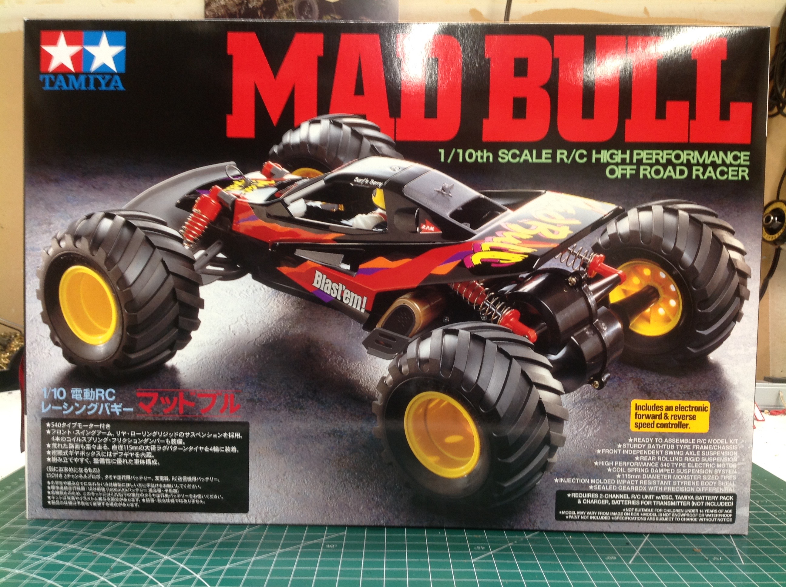
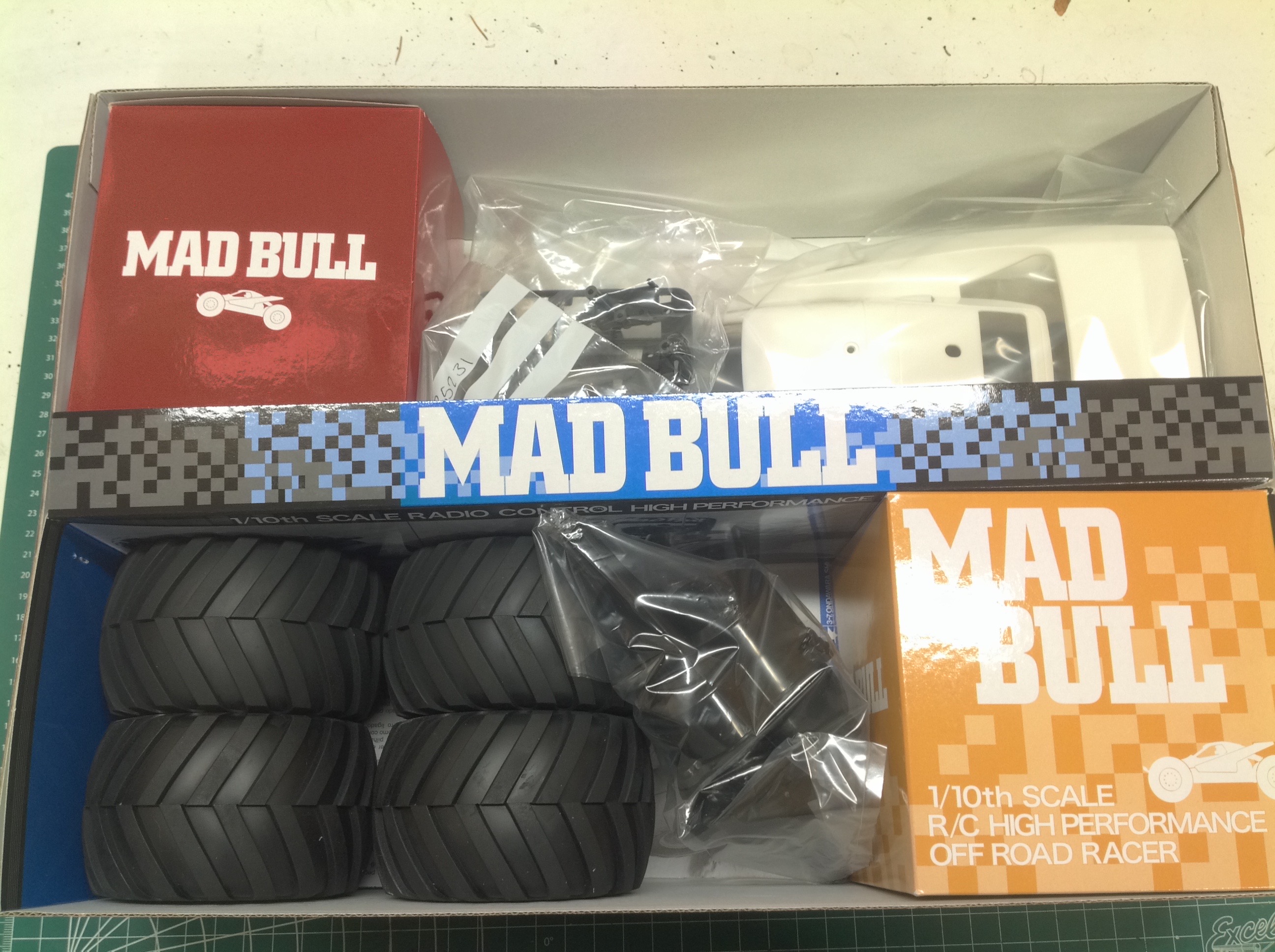
The Mad Bull comes in a large box which is mostly filled with
tires. The cover features a photograph rather than the traditional
Tamiya hand drawn art.
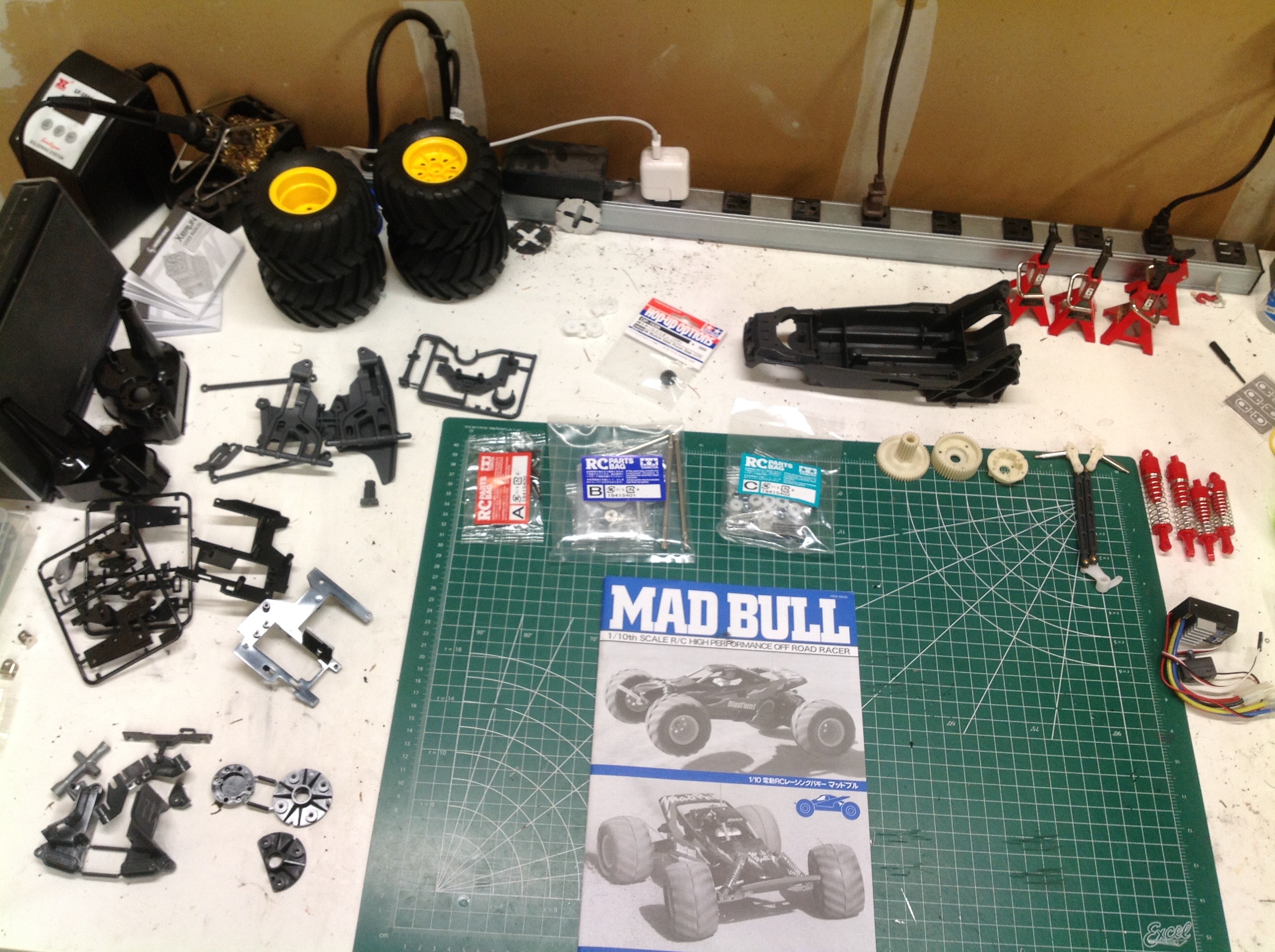
It doesn't take long to look at this photo and see that there is not
much to this kit. There are only a handful of parts, a giant
chassis tub, and the tires. The body is still in the box while I
build the chassis.
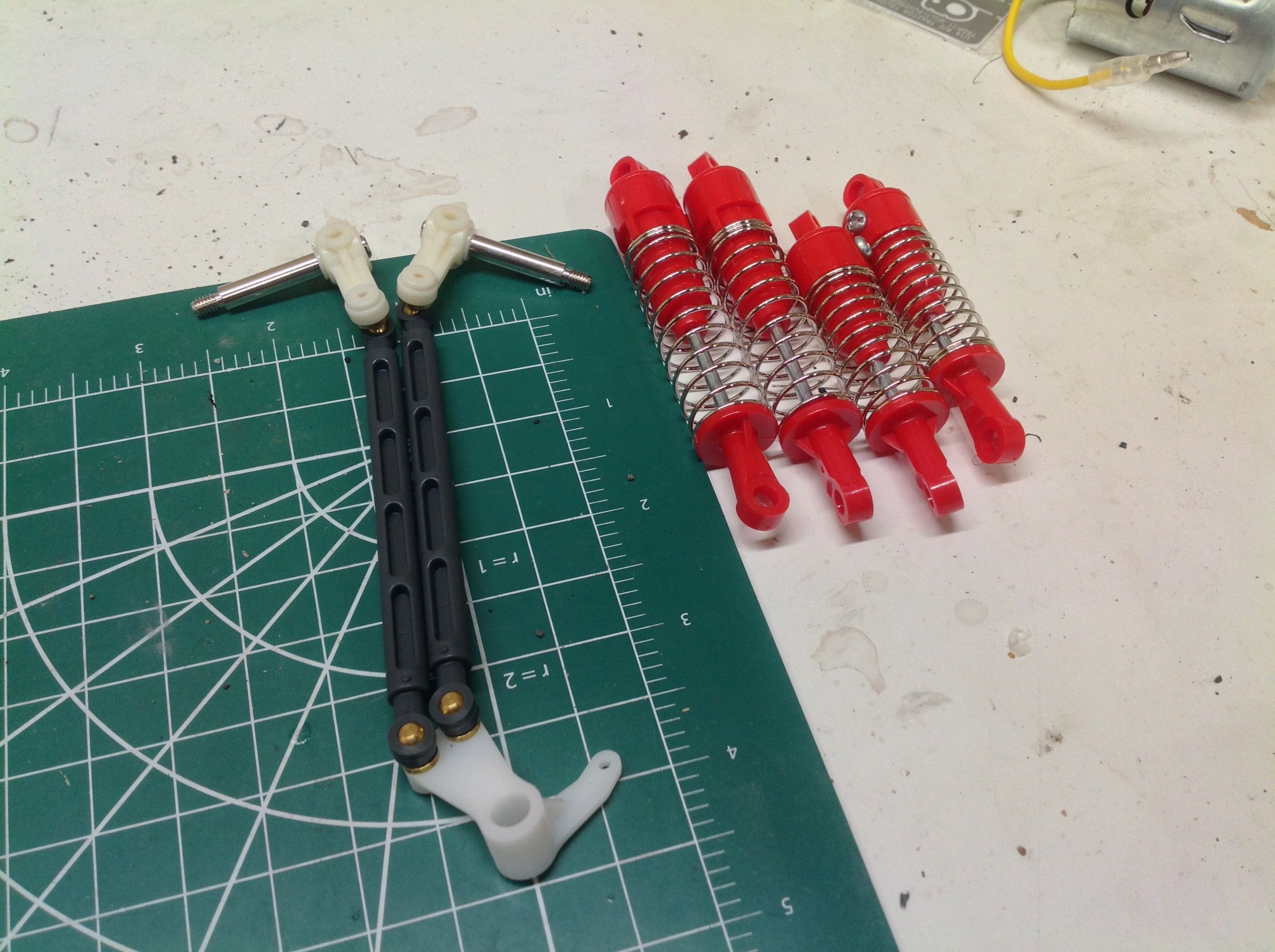
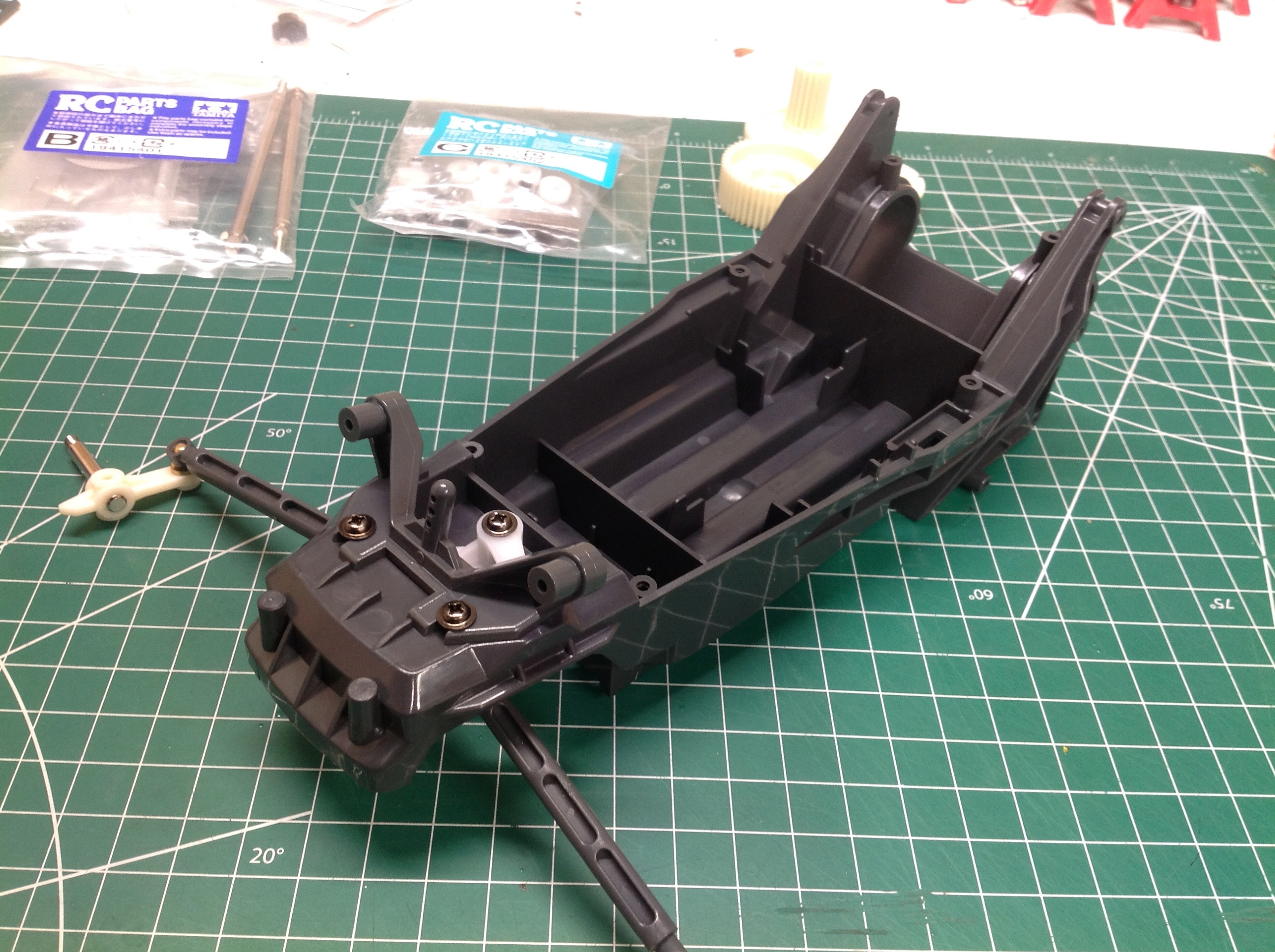
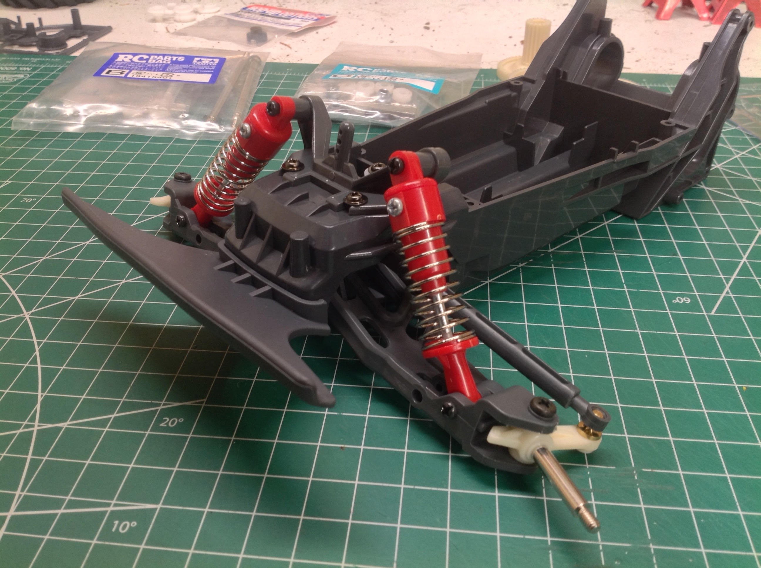
In case the model wasn't already simple enough for you, the "shocks"
come assembled and so does the steering linkage. These are not
oil shocks so they would have been dirt simple to assemble, but here
they are. The steering and hub assembly slips through a slot in
the chassis tub and then the crank slides over a post and is secured
with a flanged screw. We're only one step in and it already looks
like a chassis.
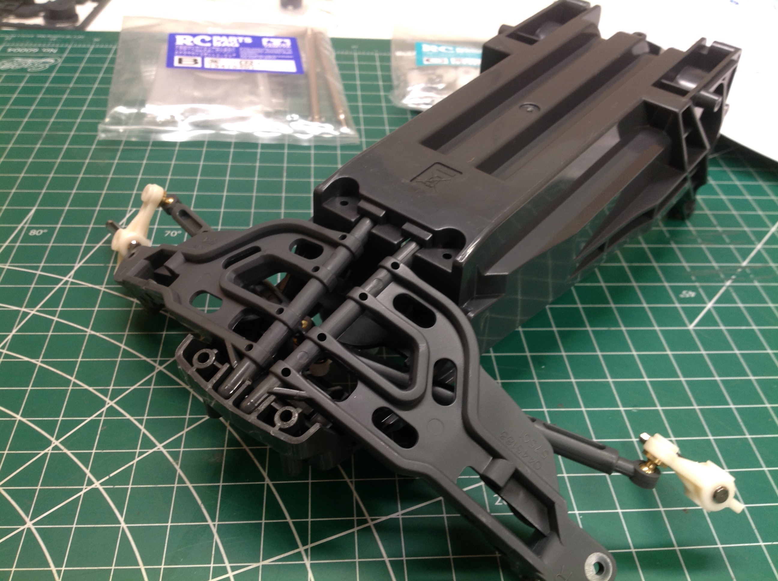
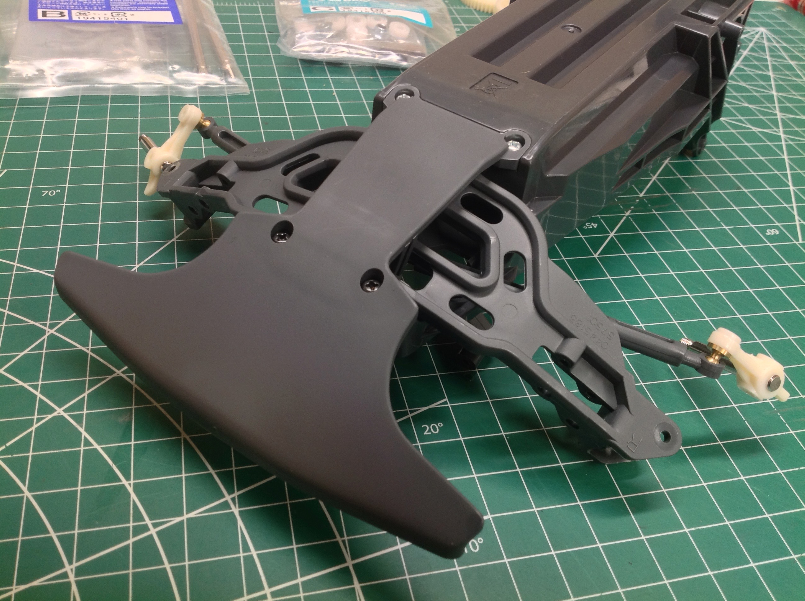
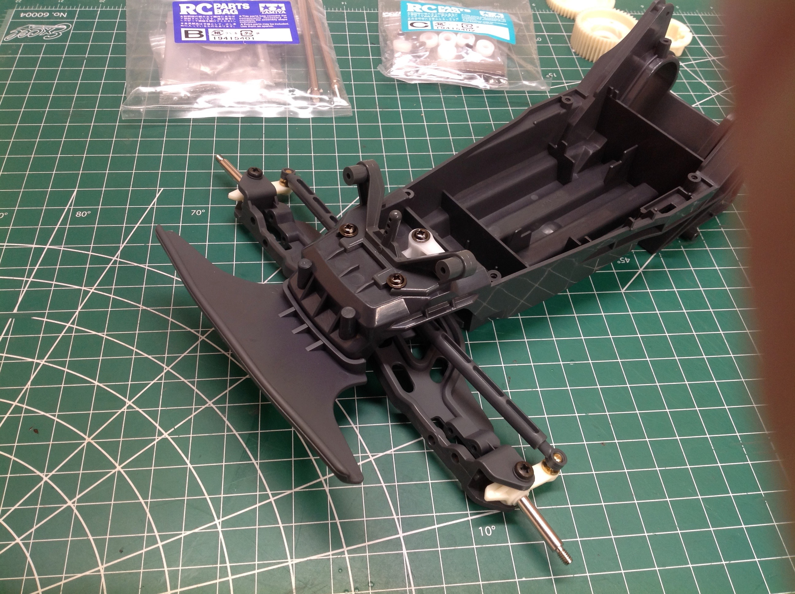
The front suspension uses swing arms which insert from the bottom.
You can see that the rotation axis tips the arms slightly
forward. The attachment of the front bumper retains the arms.
There are no upper arms, instead the C-hub is built directly into the
lower arm. The insertion of a screw pin attaches the steering
knuckles. Once the shocks are installed, this very simple front
suspension is complete.
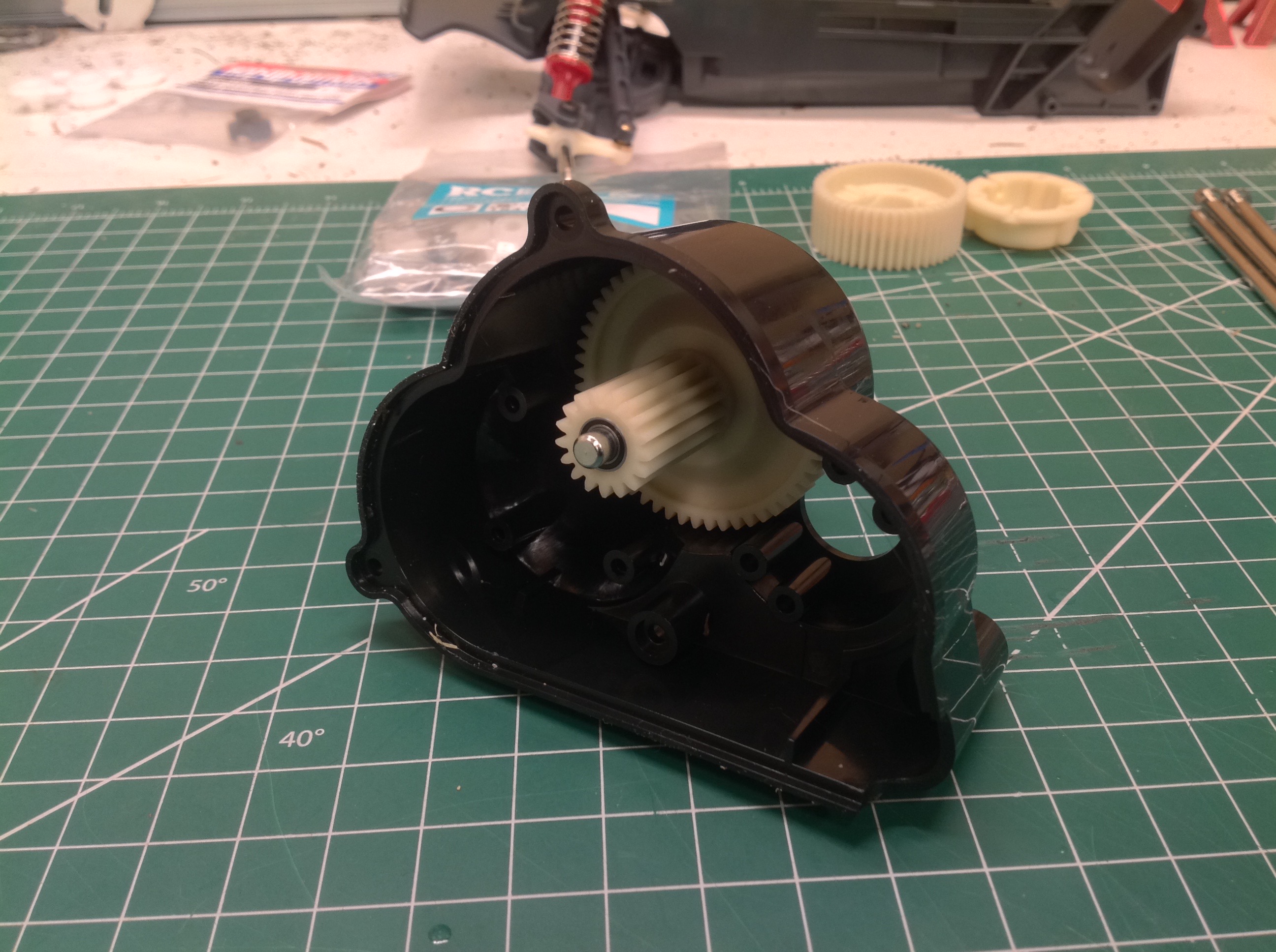
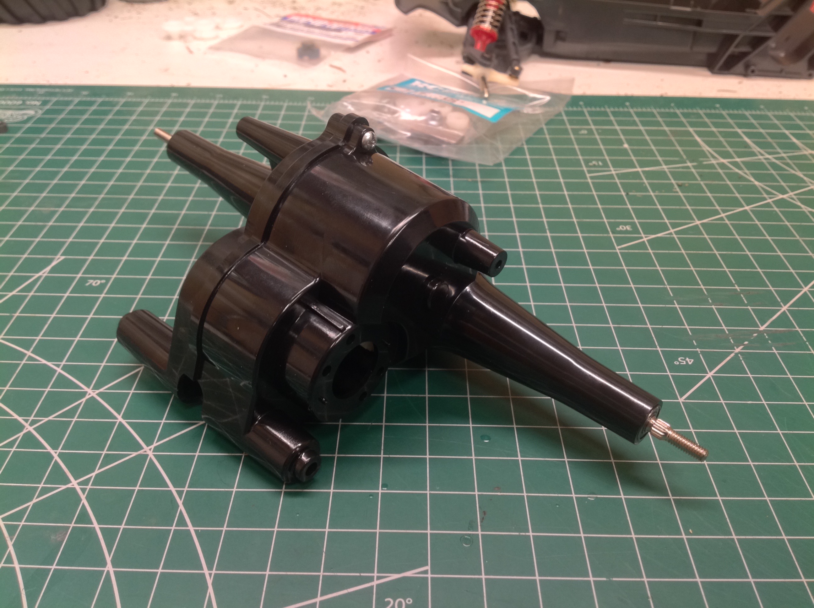
The transmission is integral to the solid rear axle and consists of only
a single stepped gear in addition to the differential. These are
some really large gear teeth so gear failures should be rare.
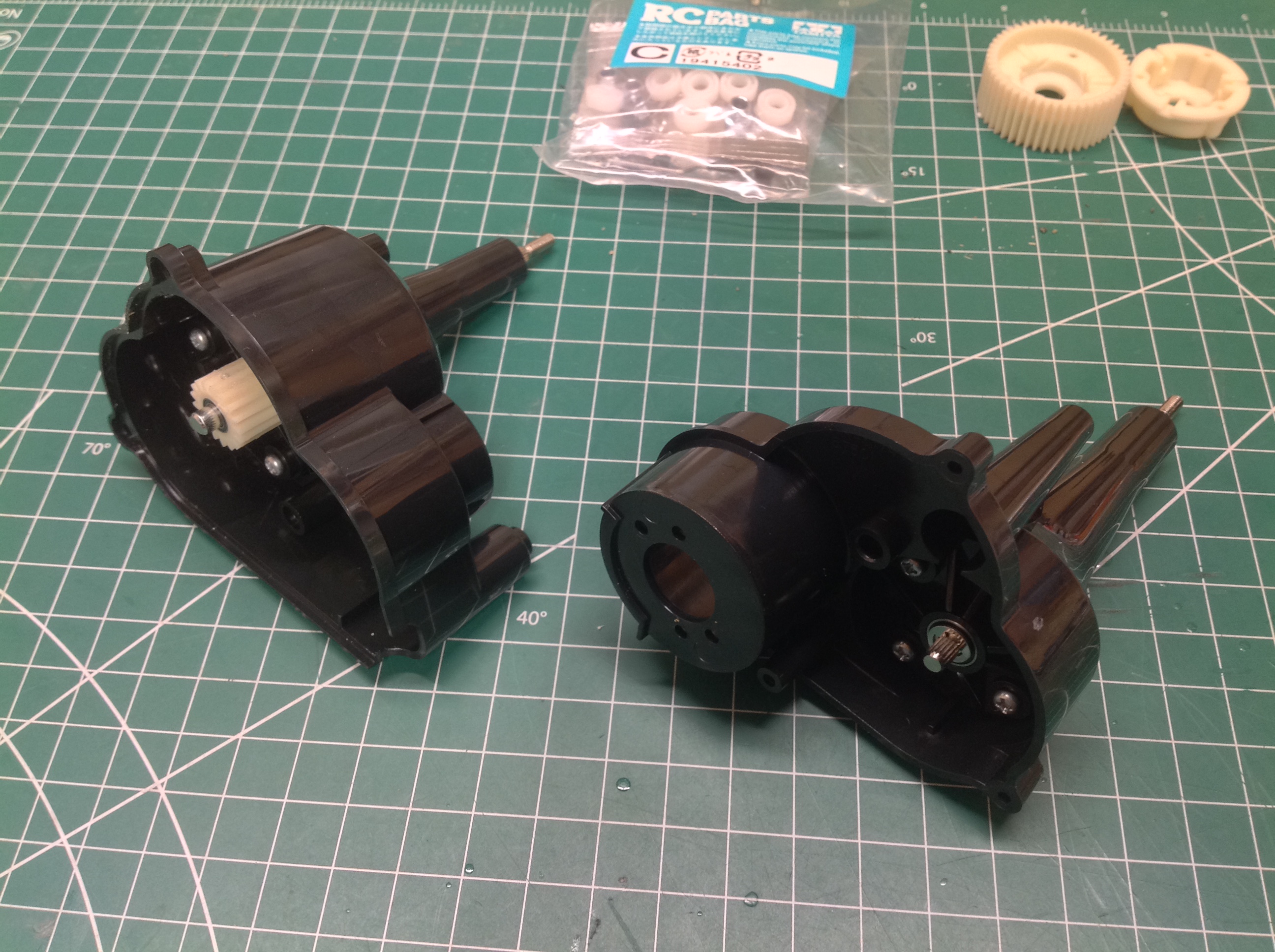
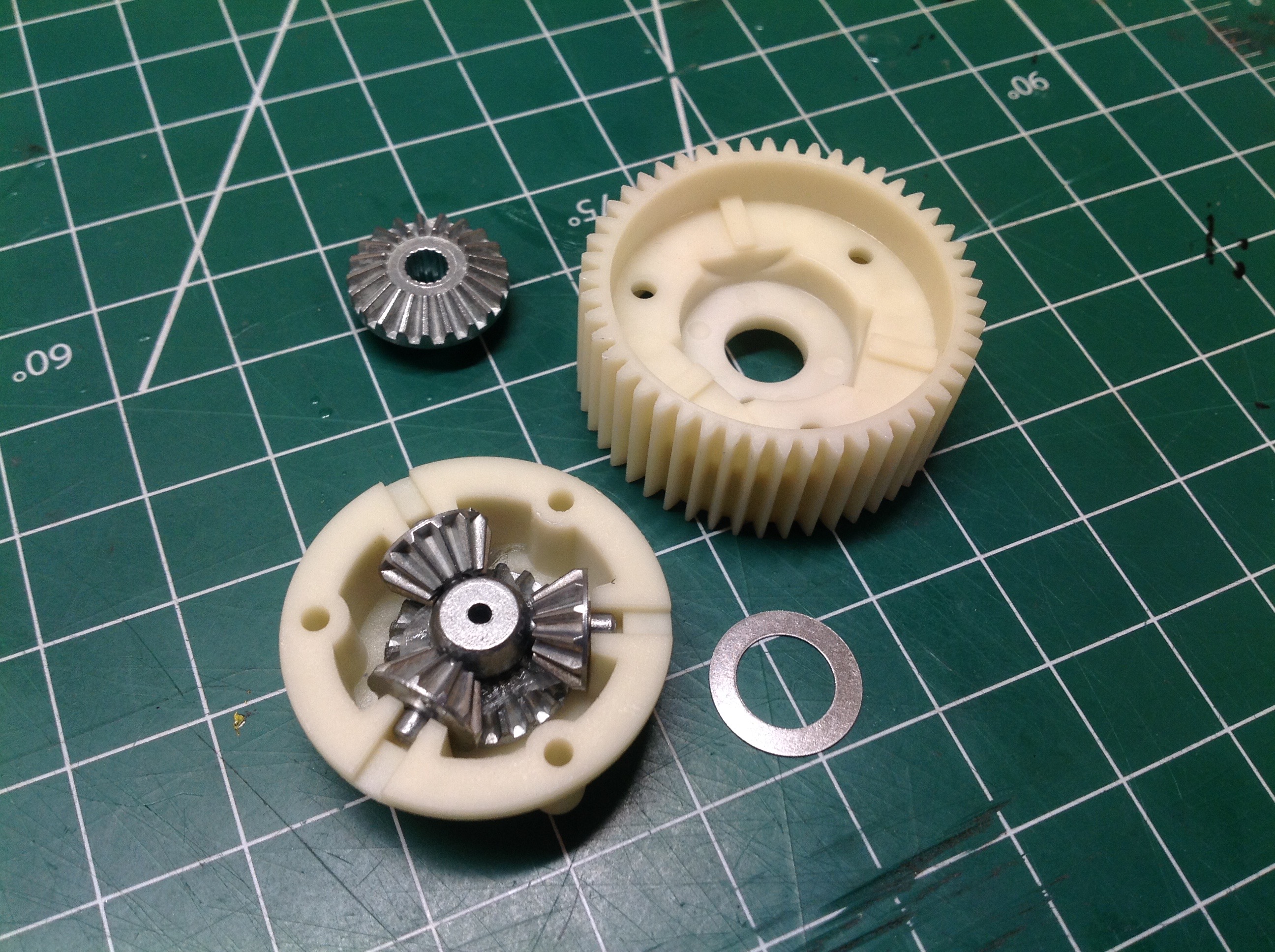
The metal differential gears sit inside a nylon spur gear housing as
shown. Once this assembly is inserted into the rear axle housing,
the two halves can be joined to complete the rear axle.
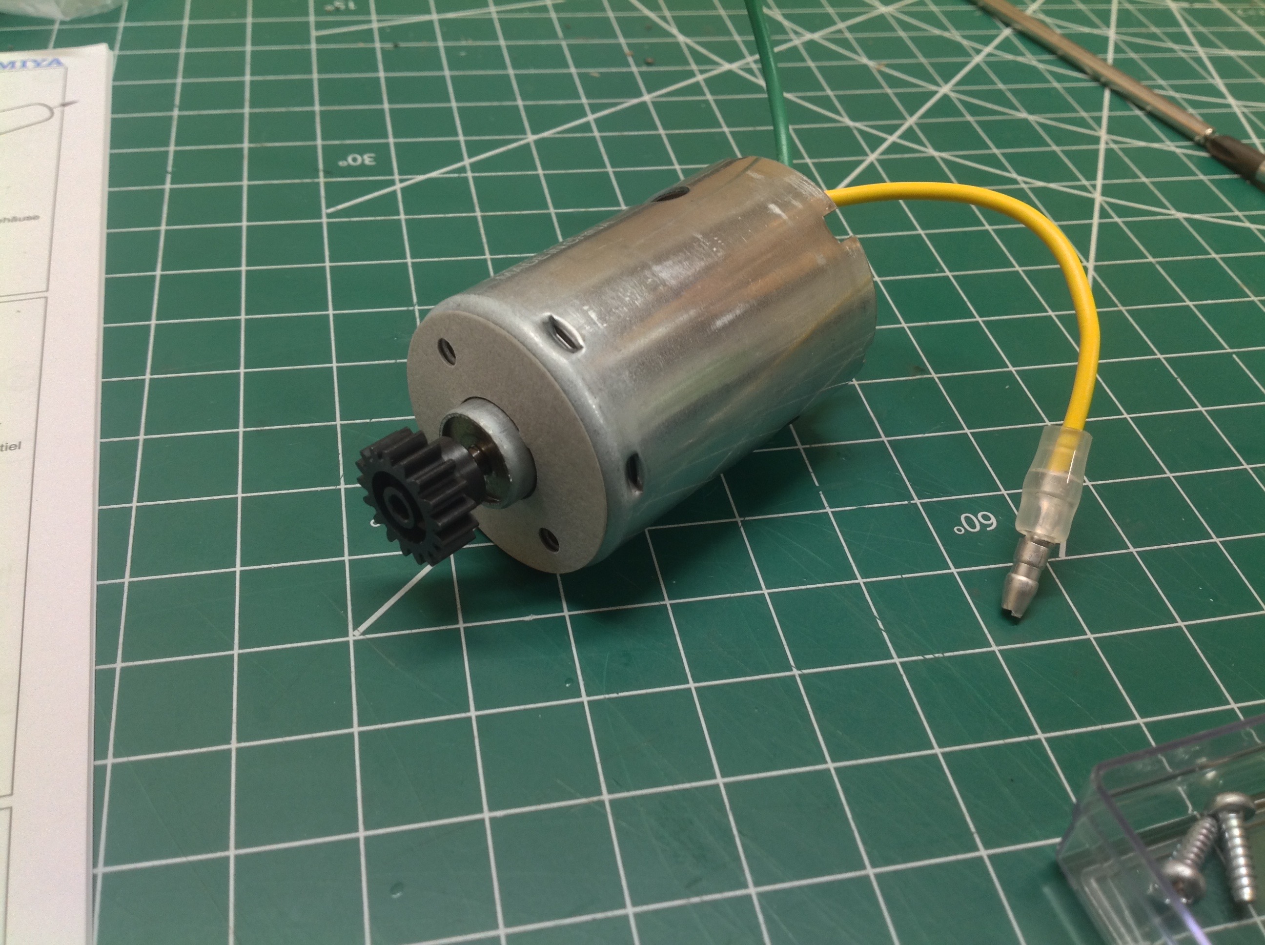
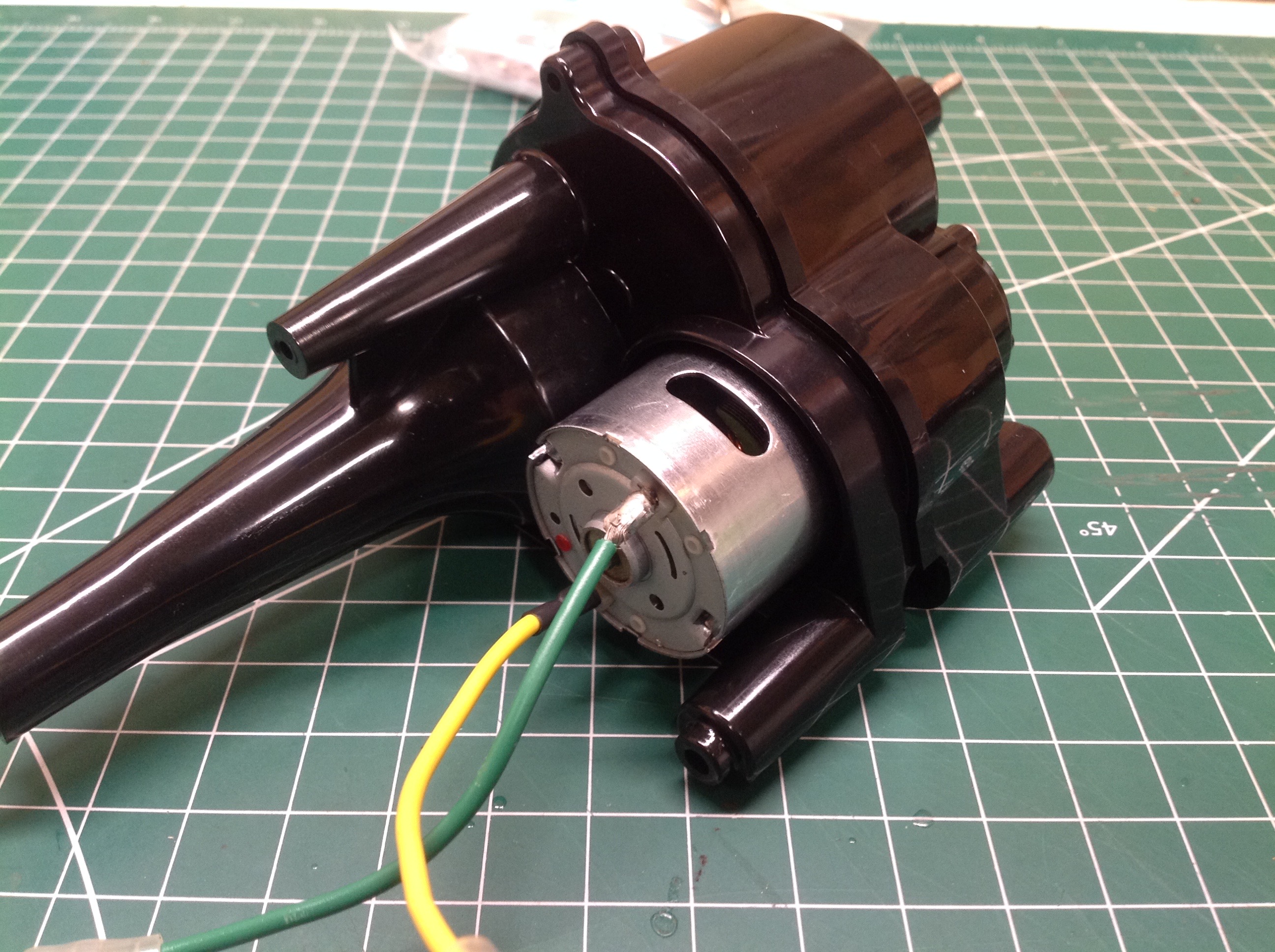
The kit comes with a silver can motor and a 17 tooth pinion. There
are two sets of motor mounting holes which suggest an optional larger
pinion, but there is no indication of what size this might be. 19T
is a reasonable guess, but I'm not sure this model would benefit from
more speed.
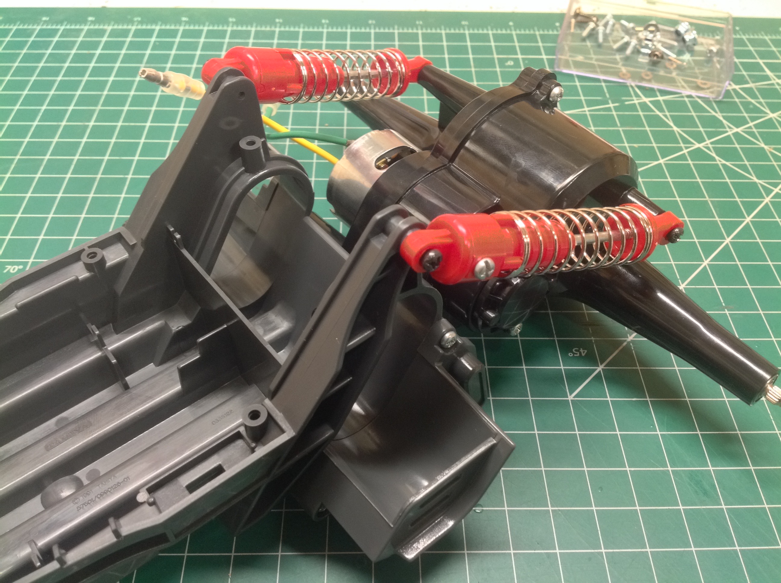
The center pivot you see at the front of the axle allows the whole thing
to swivel side to side without bouncing up and down like it does on the
Grasshopper or Lunch Box. Note the extremely shallow angle of the
rear shocks.
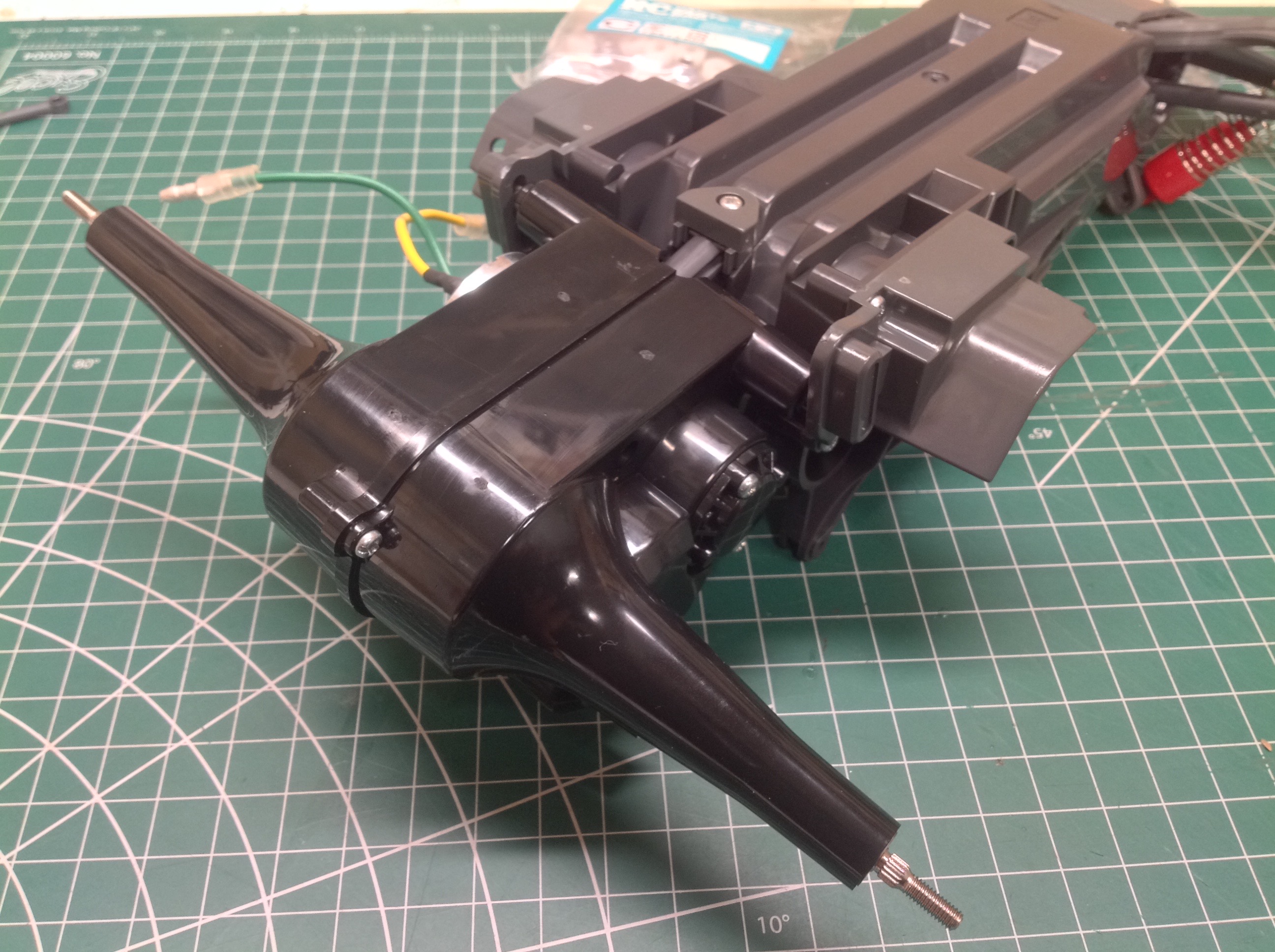
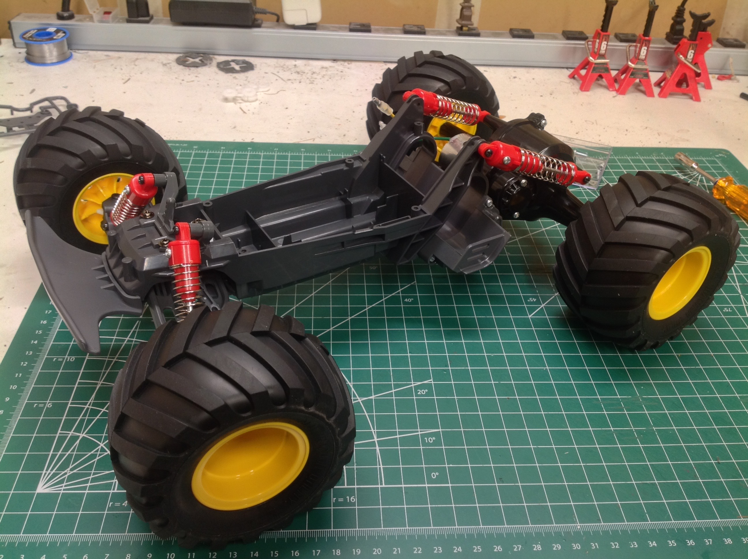
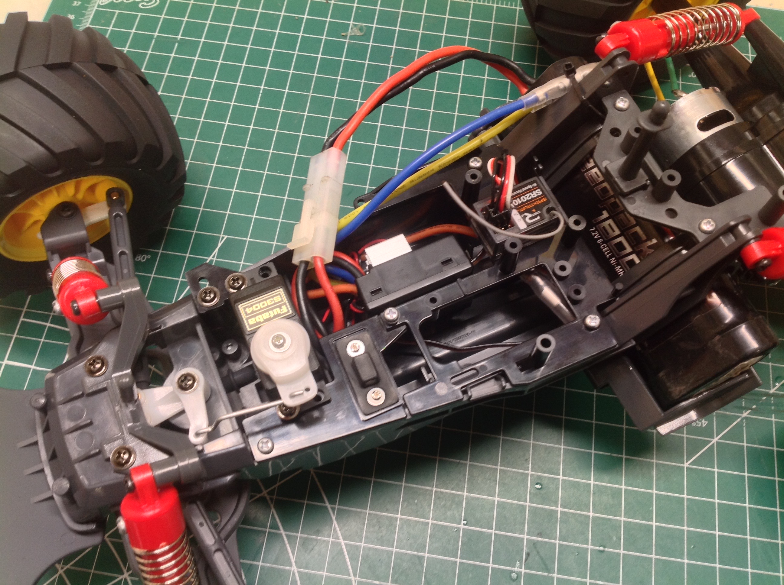
That's it. Now the wheels and tires can be installed along with
the electronics. There is quite a bit of space available. It
is interesting that there is clearly space for a second servo to drive a
mechanical speed controller even though this model was never available
with one, nor was any DT-01.
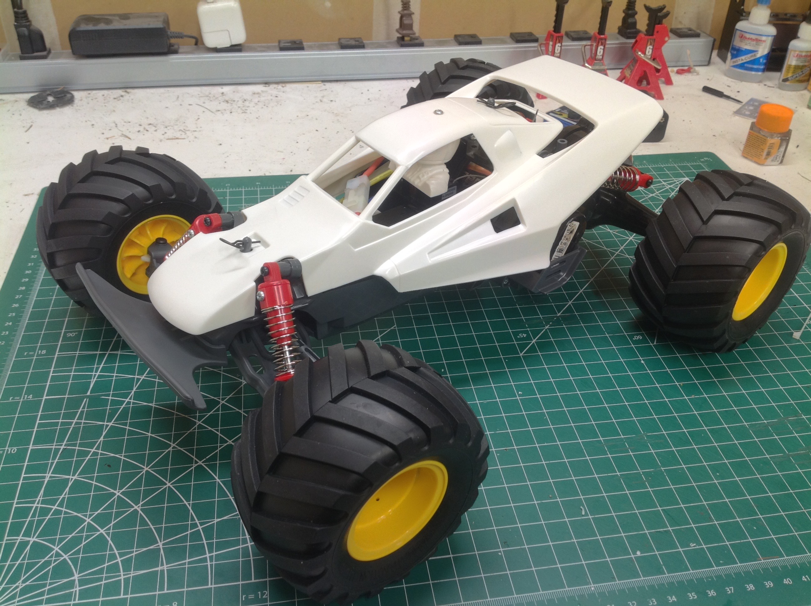
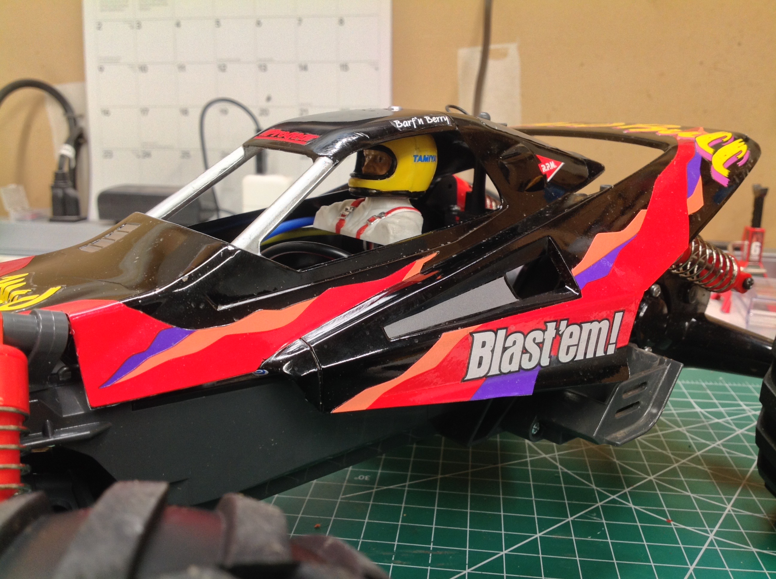
The Grasshopper II body is a single part. It just needs to be
painted uniform black so the stickers can be applied. There is
also a driver torso and head to paint.
©2020 Eric Albrecht