Kyosho Turbo Optima Project
Page 1: Building the Chassis
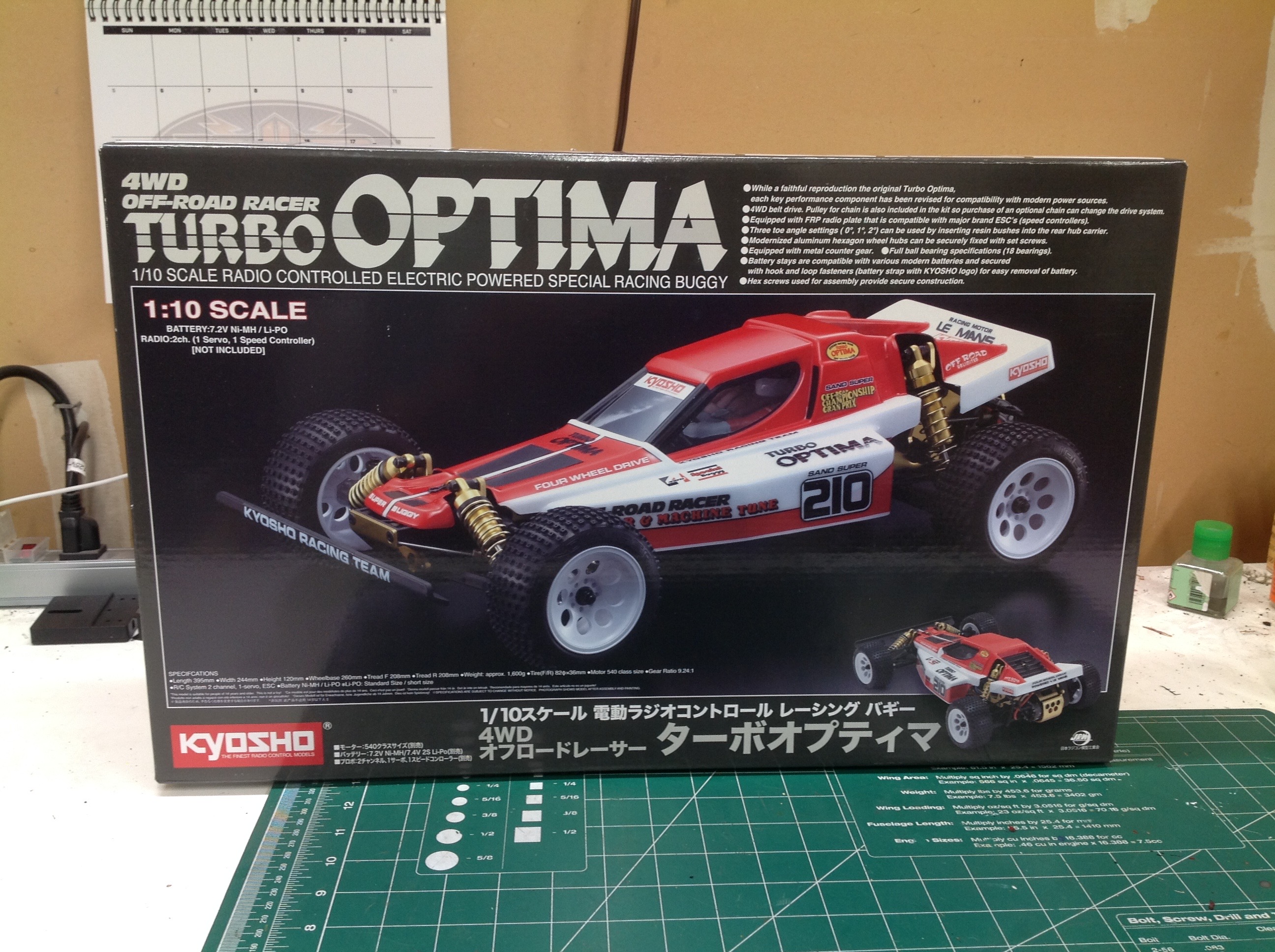
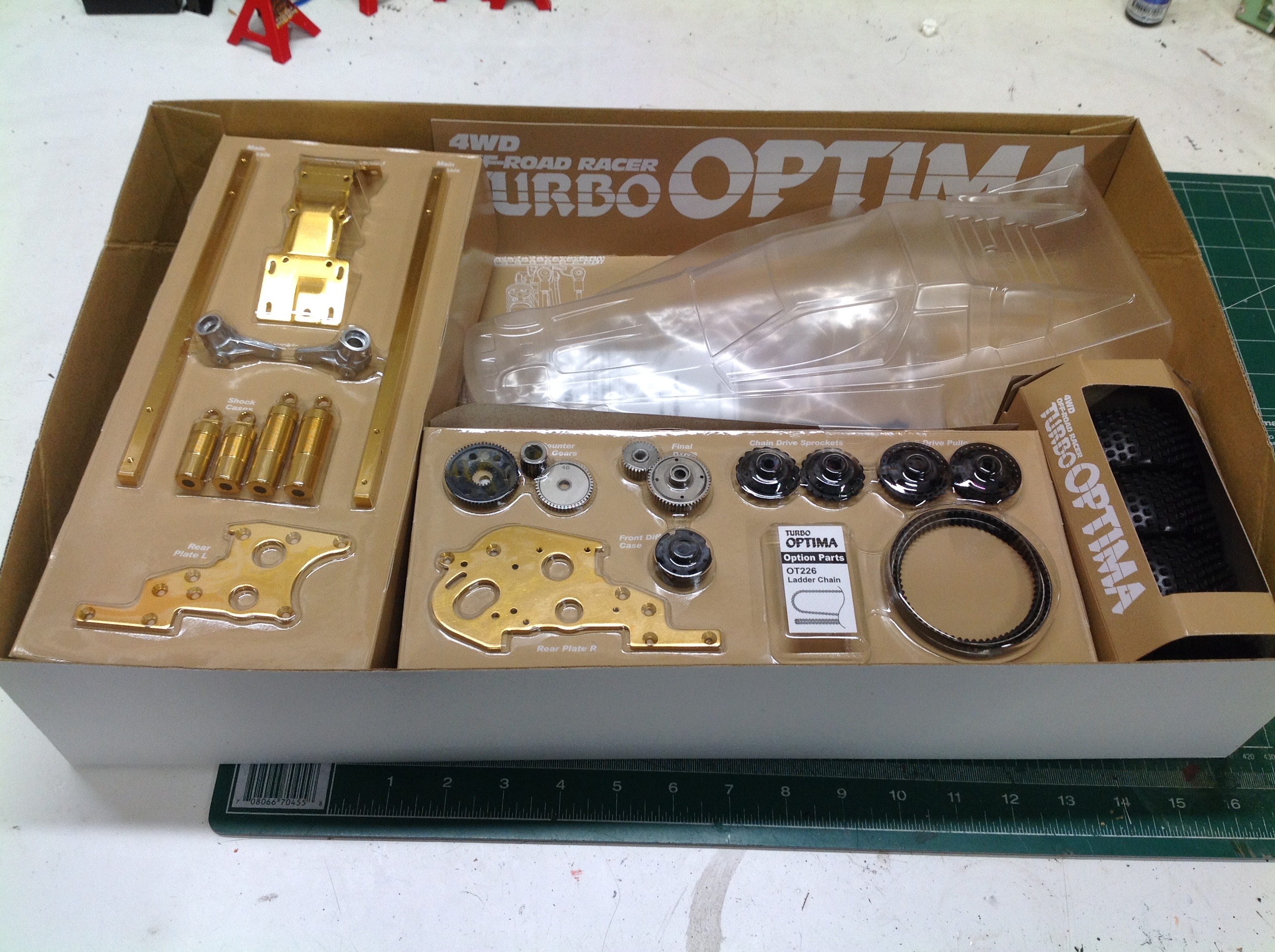
The Turbo Optima box is not super exciting on the outside. In is a
fairly plain black box with a photograph of the product. On the
inside, however, things are quite a bit better. Here we see the
gorgeous gold anodized parts presented in blister packs along with some
of the special parts like the pulleys and belt.
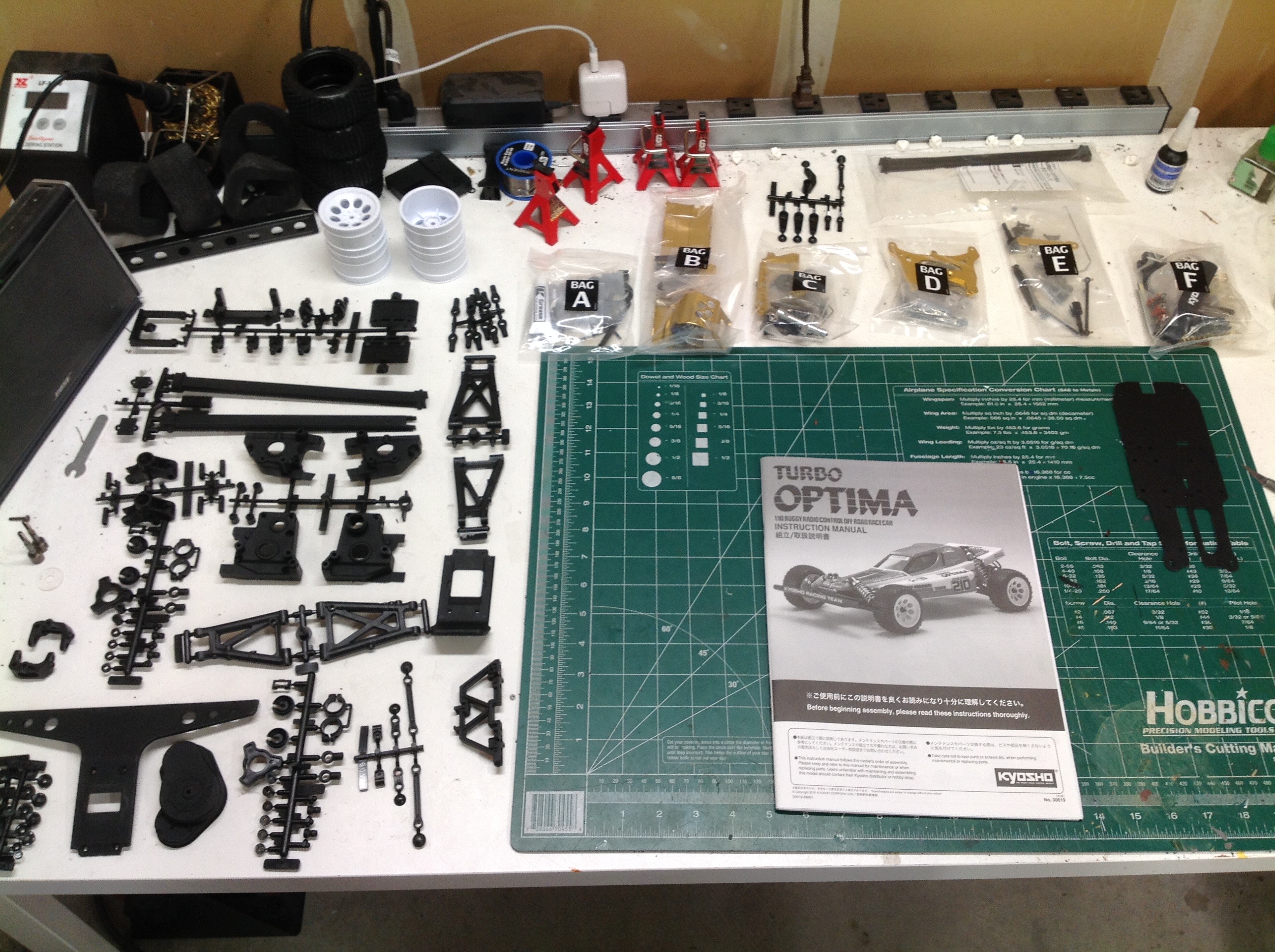
The parts inside the box are sorted as shown. There are series of
loose plastic parts trees and also a set of 6 sequentially labeled bags
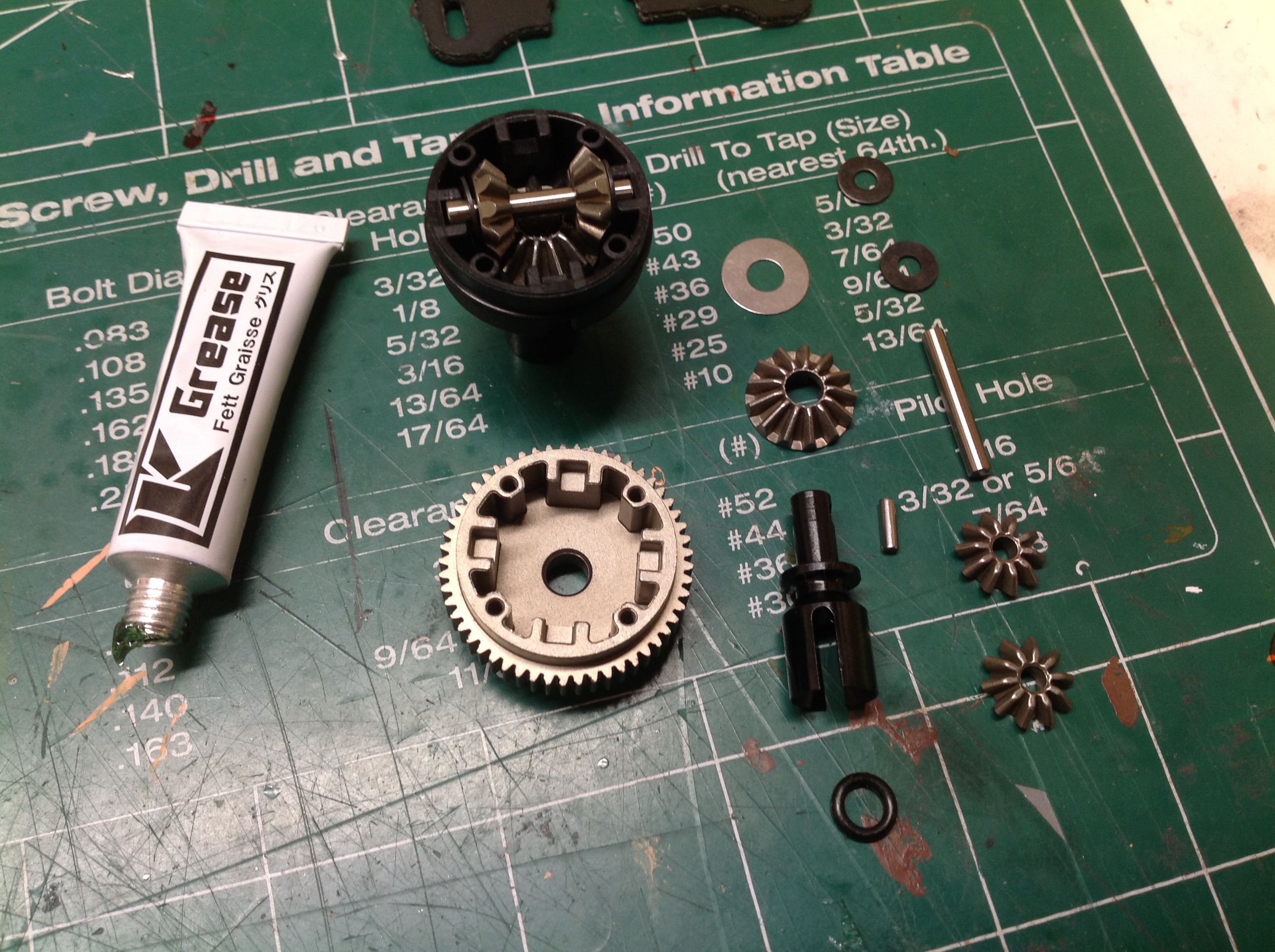
of hardware and specialty parts. Step 1 begins with the parts for
the differentials. Each step shows the parts required for that
step so you can find and arrange them ahead of time. Kyosho
instructions are very well done and clear with excellent graphics.
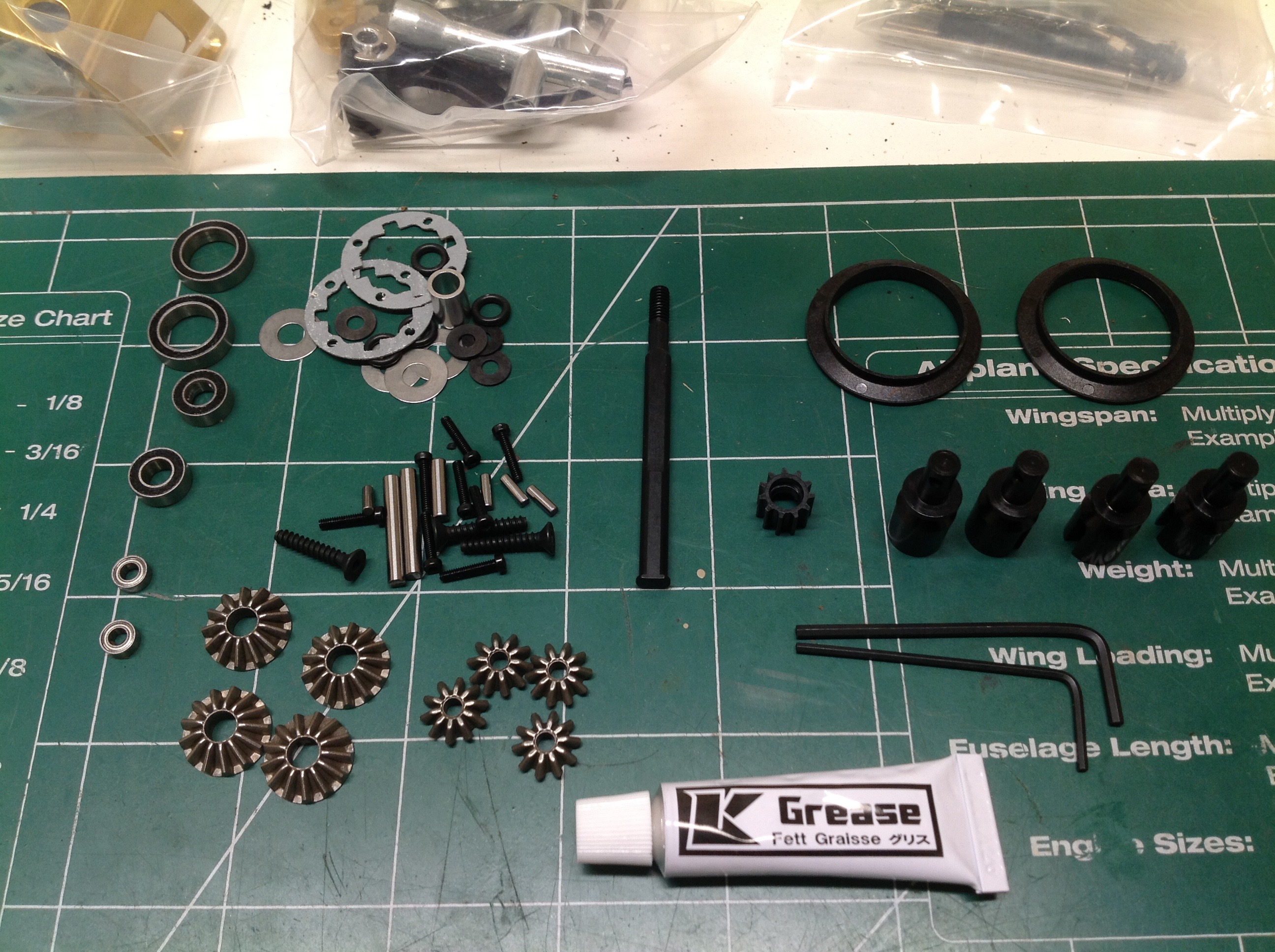
The first step also includes the hex keys and some nice black grease.
The front and rear differential internals are identical with metal
gears, but externally the rear incorporates a spur gear. This is a
sealed diff unit so you can load it up with grease or oil as you
choose.
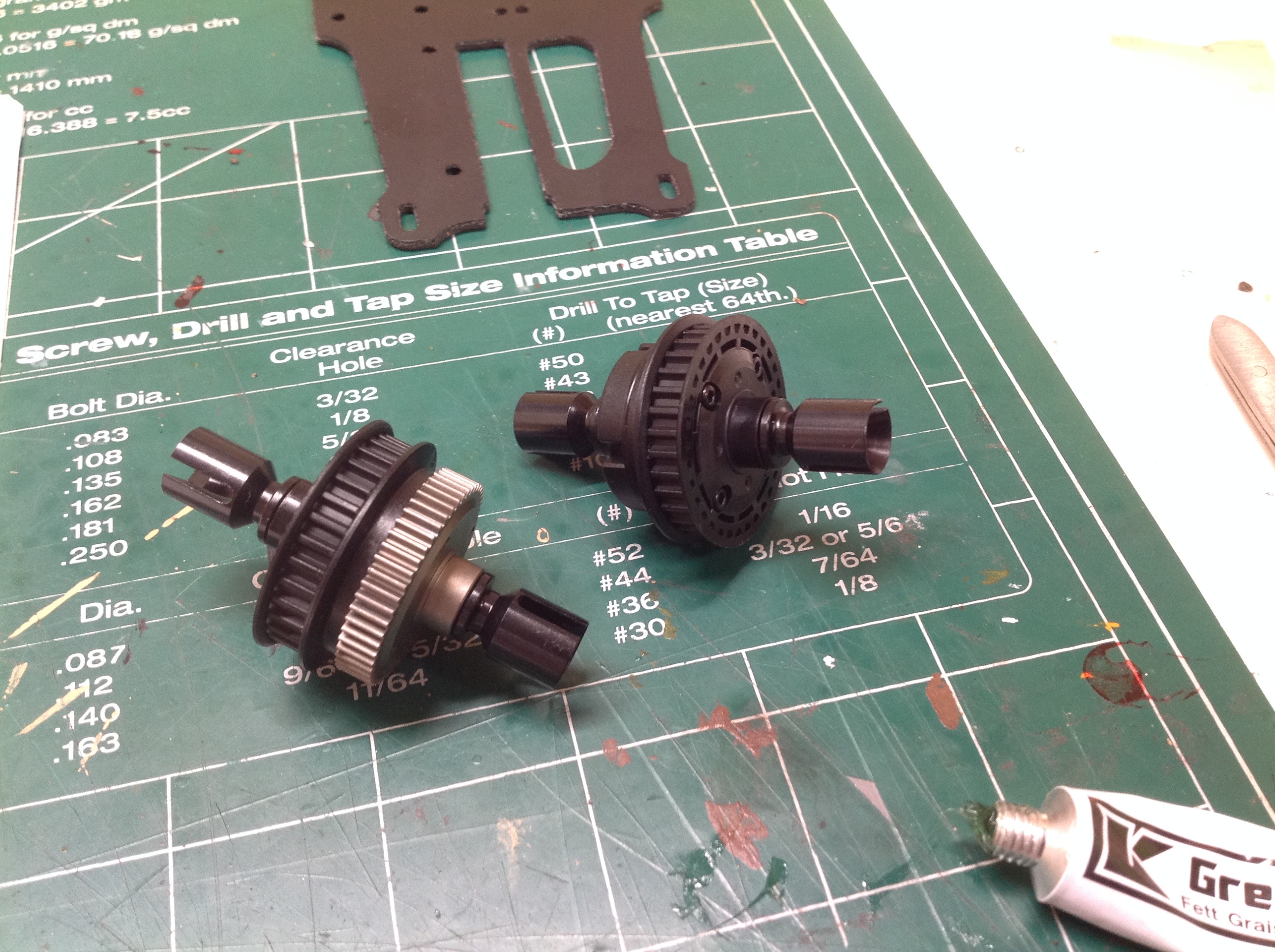
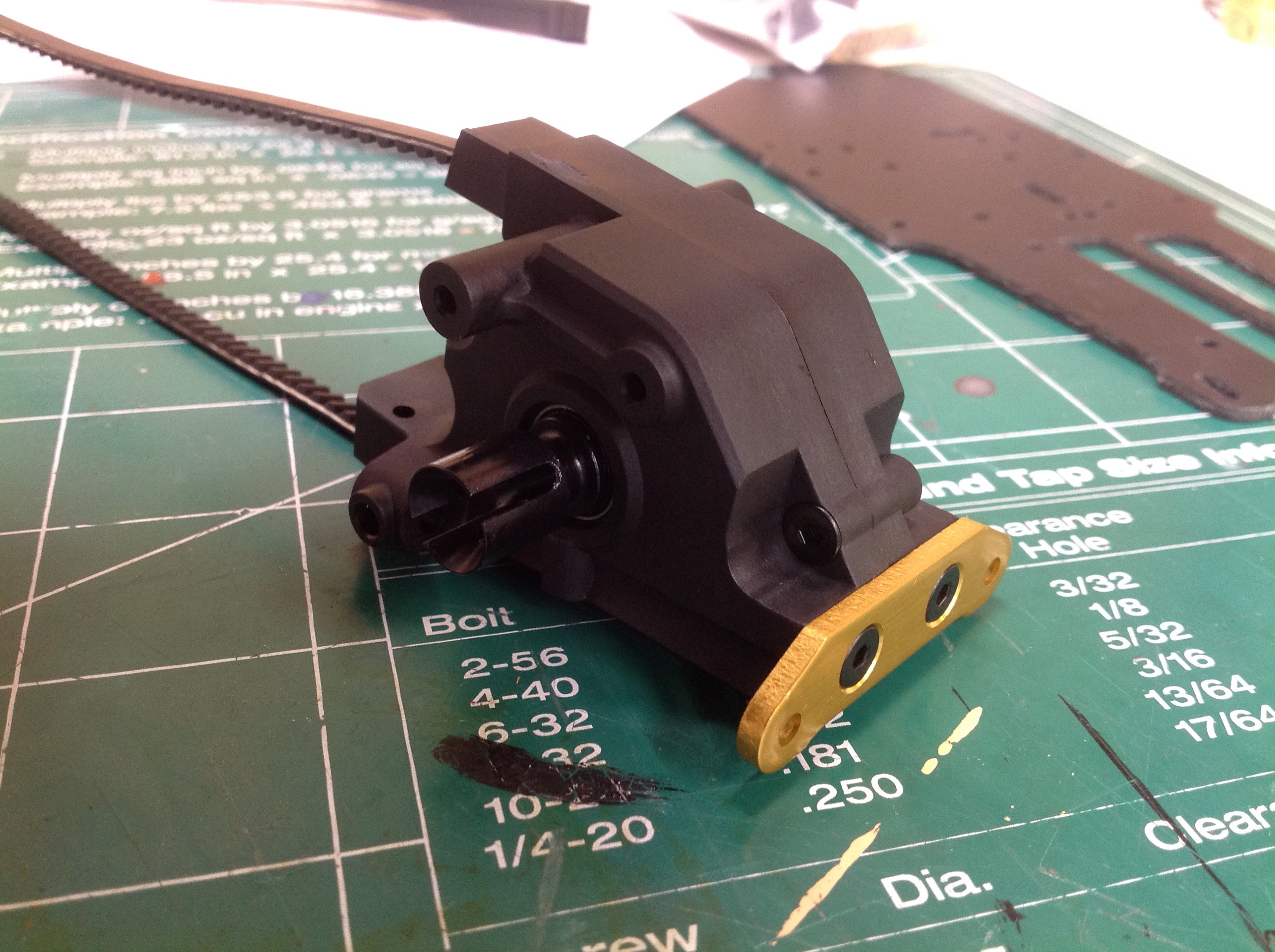
The differential housing is plastic and supports ball bearings.
The tiny cog you see is an idler support for the belt. Not shown
is an another metal internal gear driving the differential. Shown
on the right is the completed rear differential. The protruding
shaft drives the smaller gear and will support the slipper clutch.
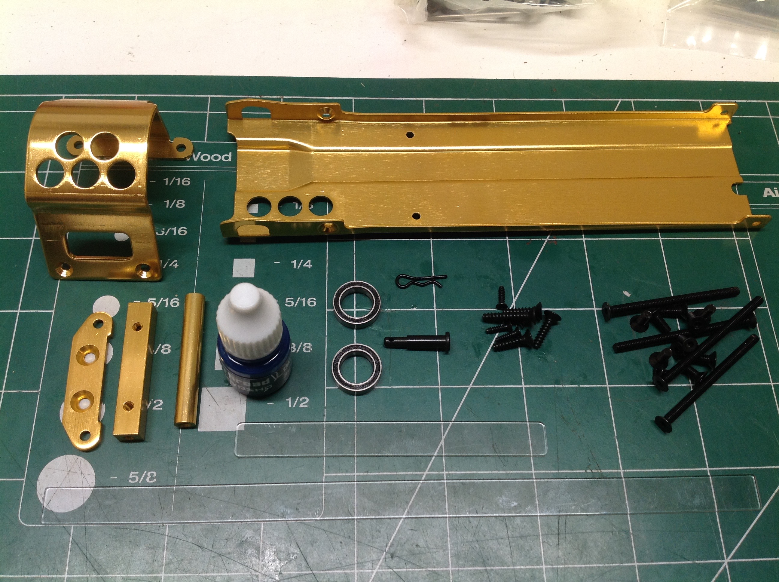
Now we get to break out those incredible gold parts. Note that
large size of the bearings. The parts you see here are from Bag B
and include the undertray and motor shroud. The small bottle is
thread lock. The first thing to install is the front suspension
bulkhead.
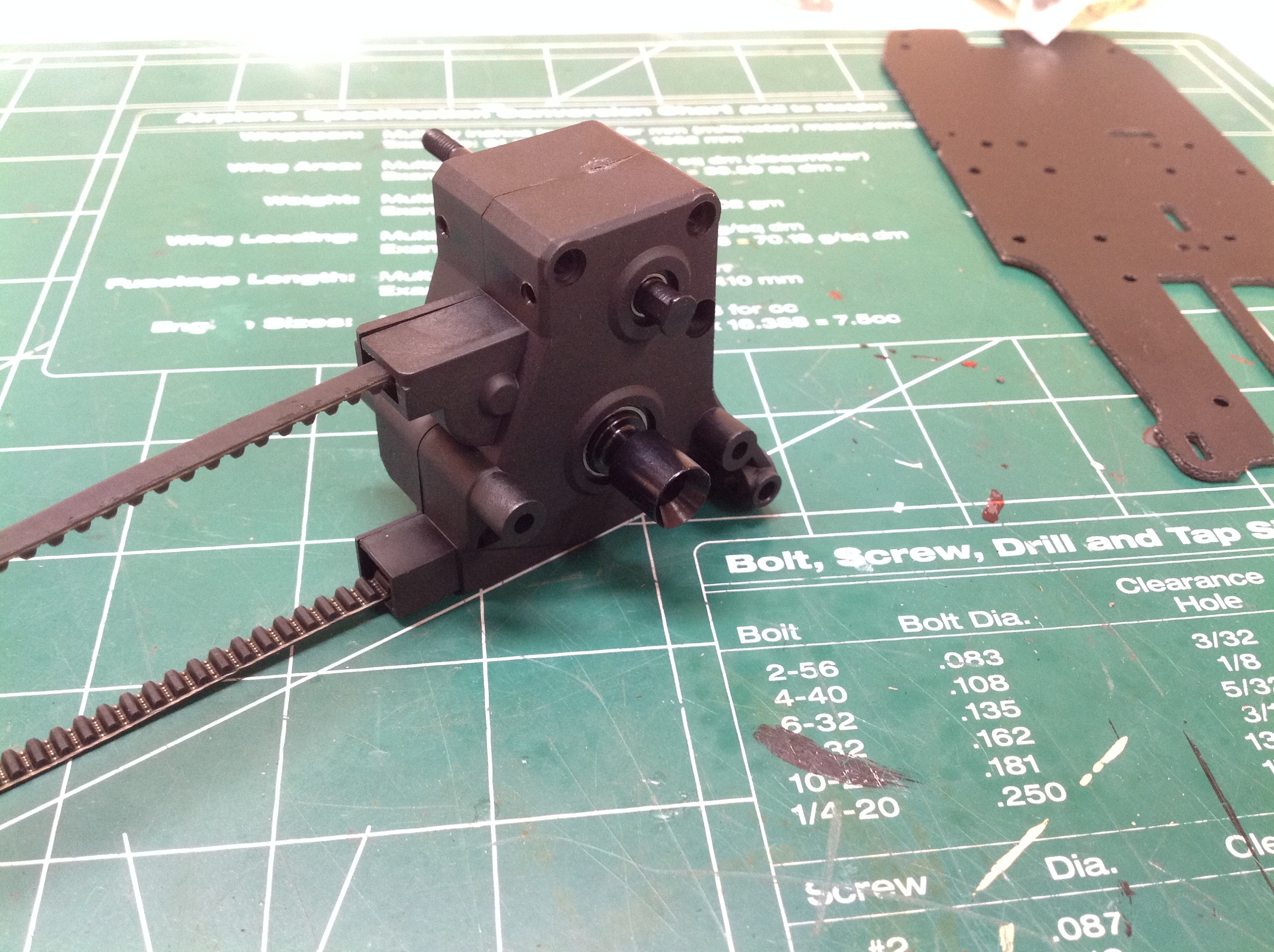
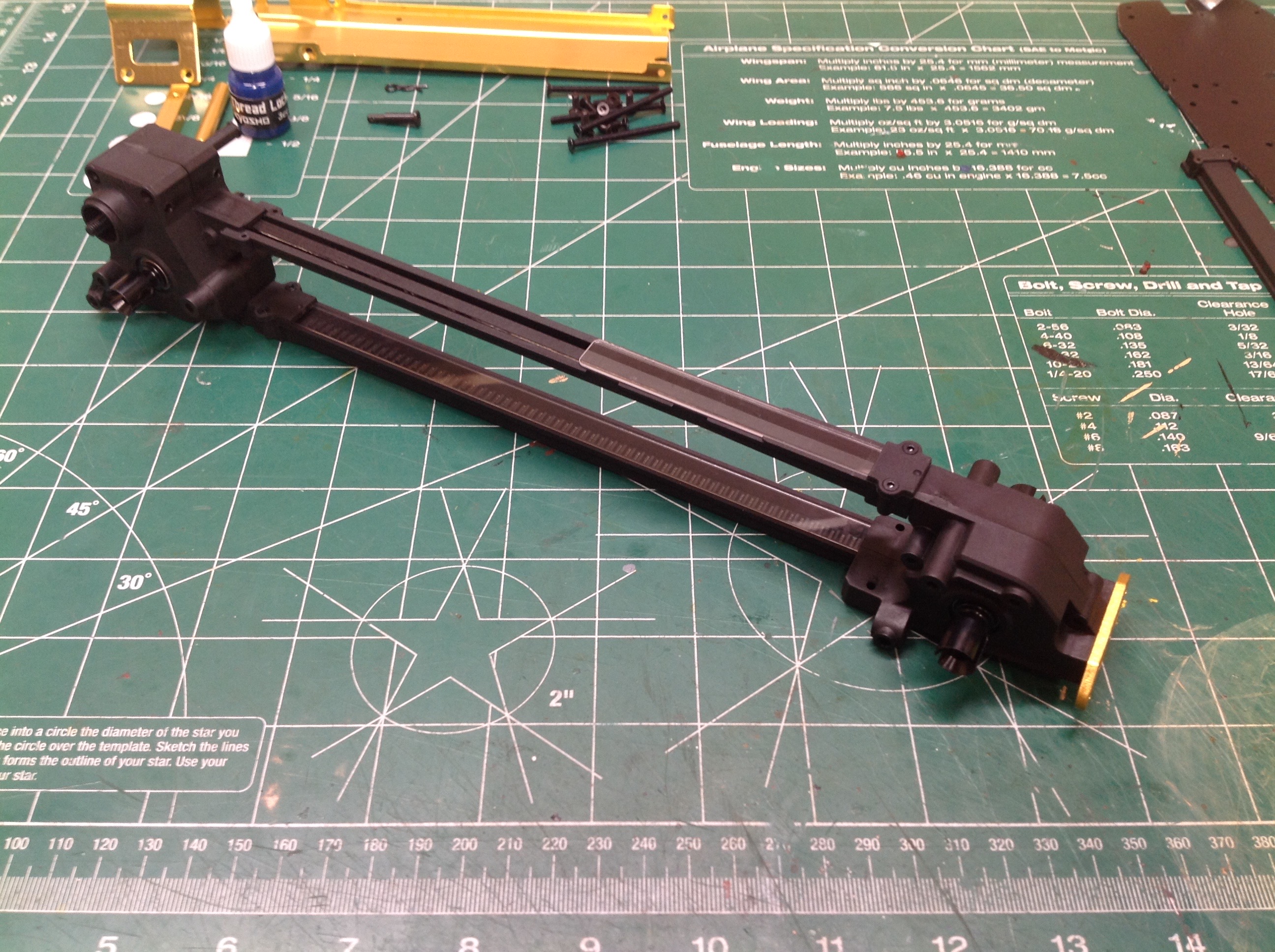
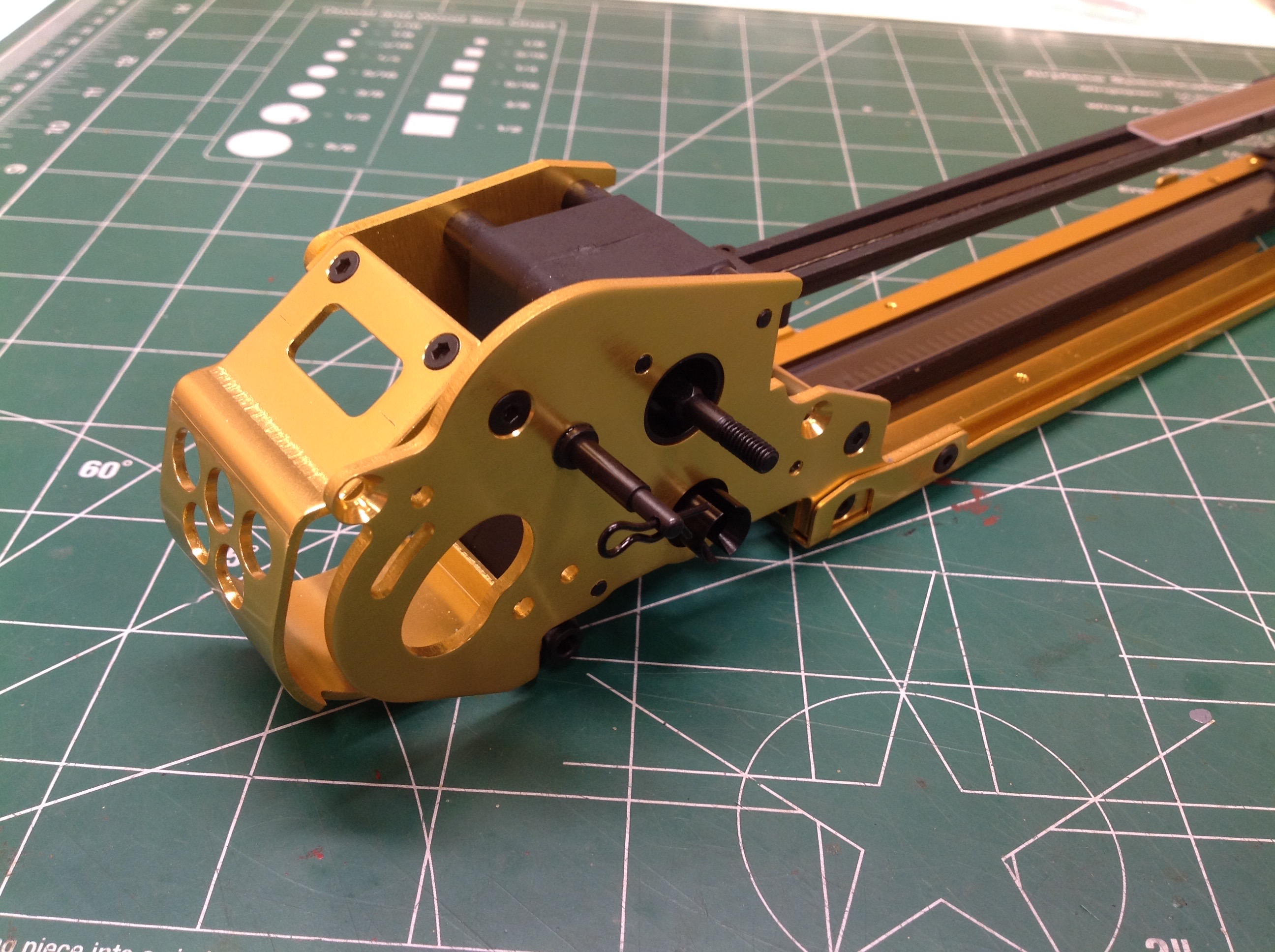
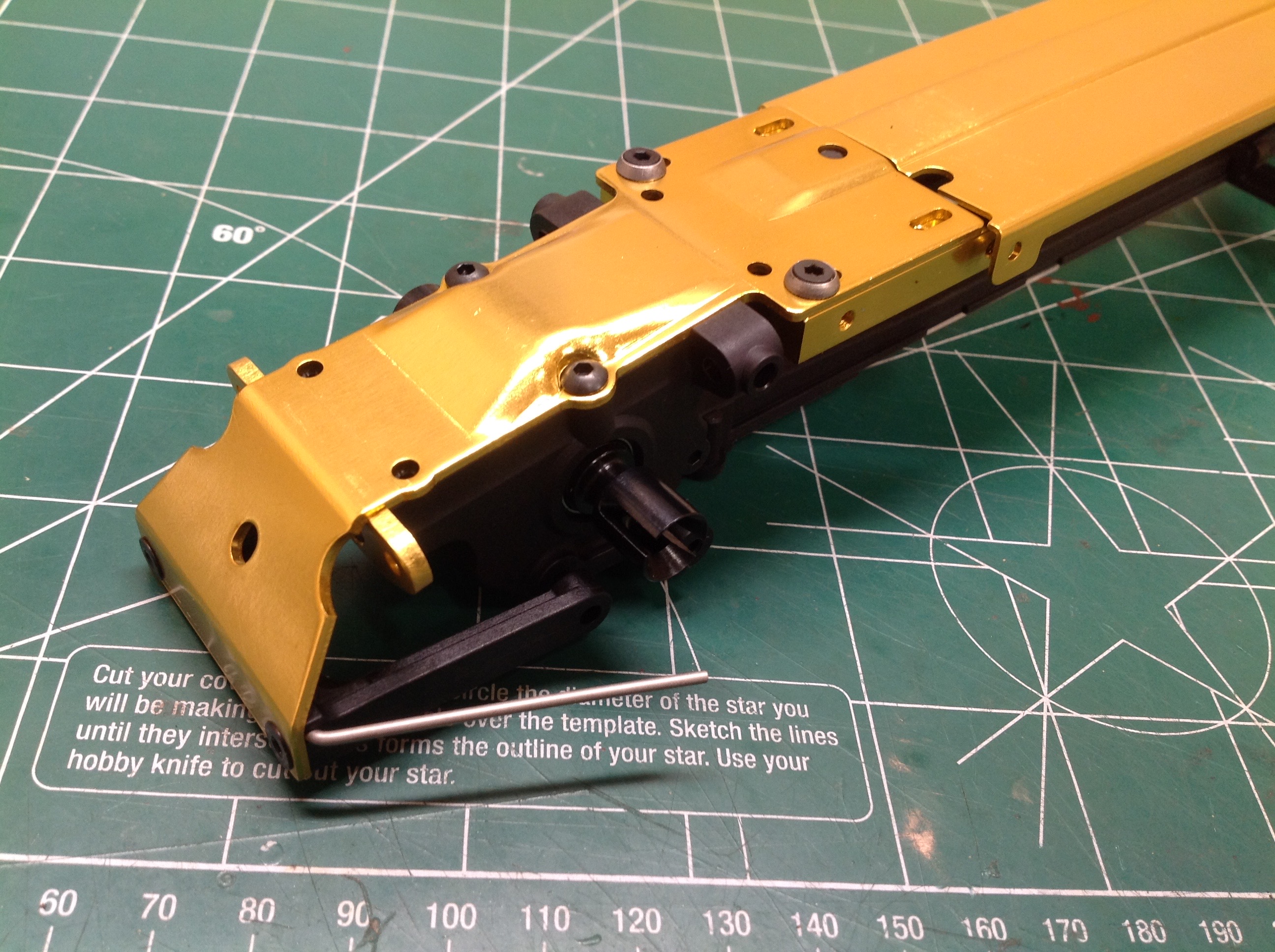
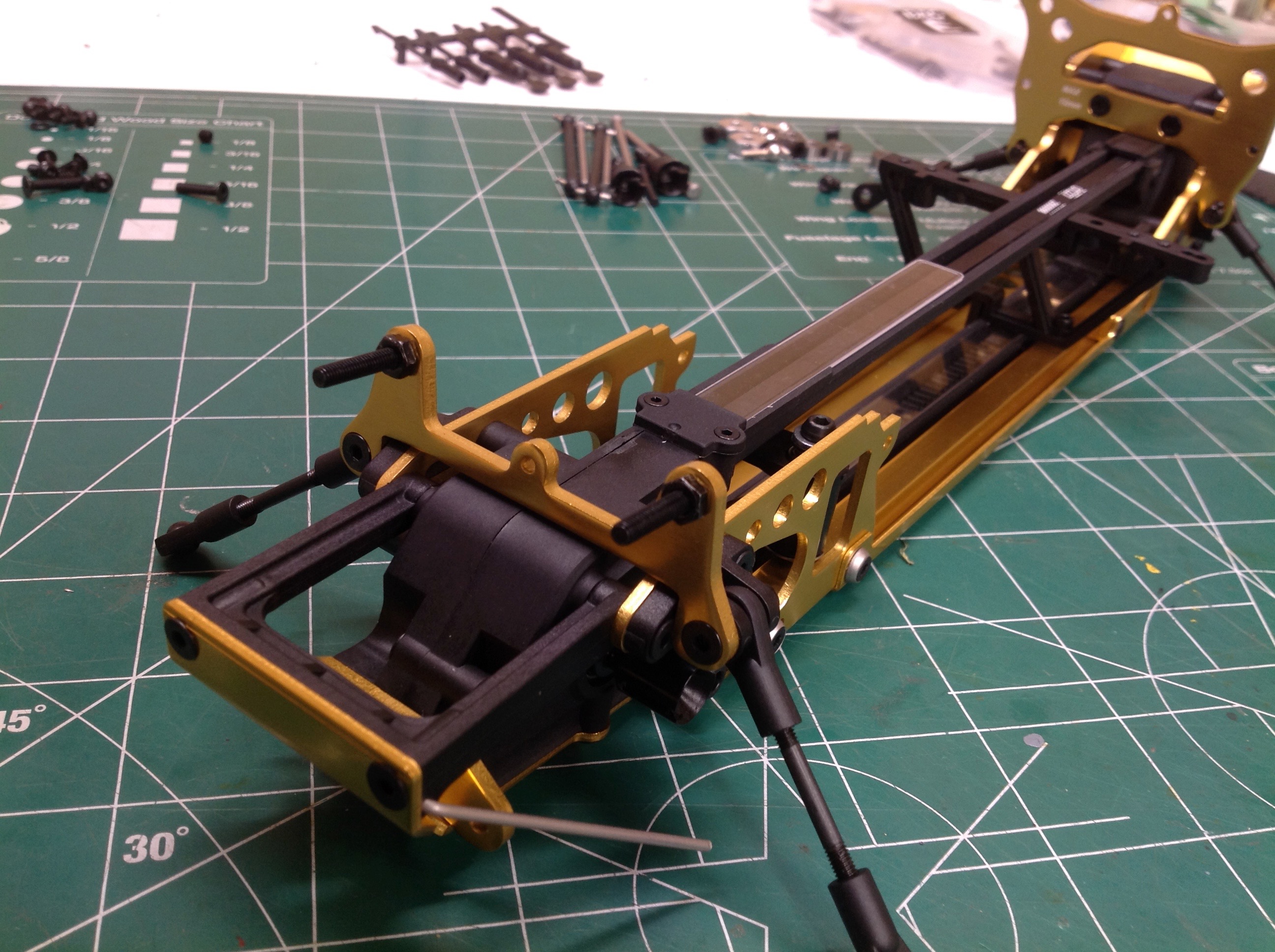
These long channels protect the belt and also serve to separate the
front and rear gearboxes. There is still play in the joint at the
front which allows the front gearbox to be slid to tension the
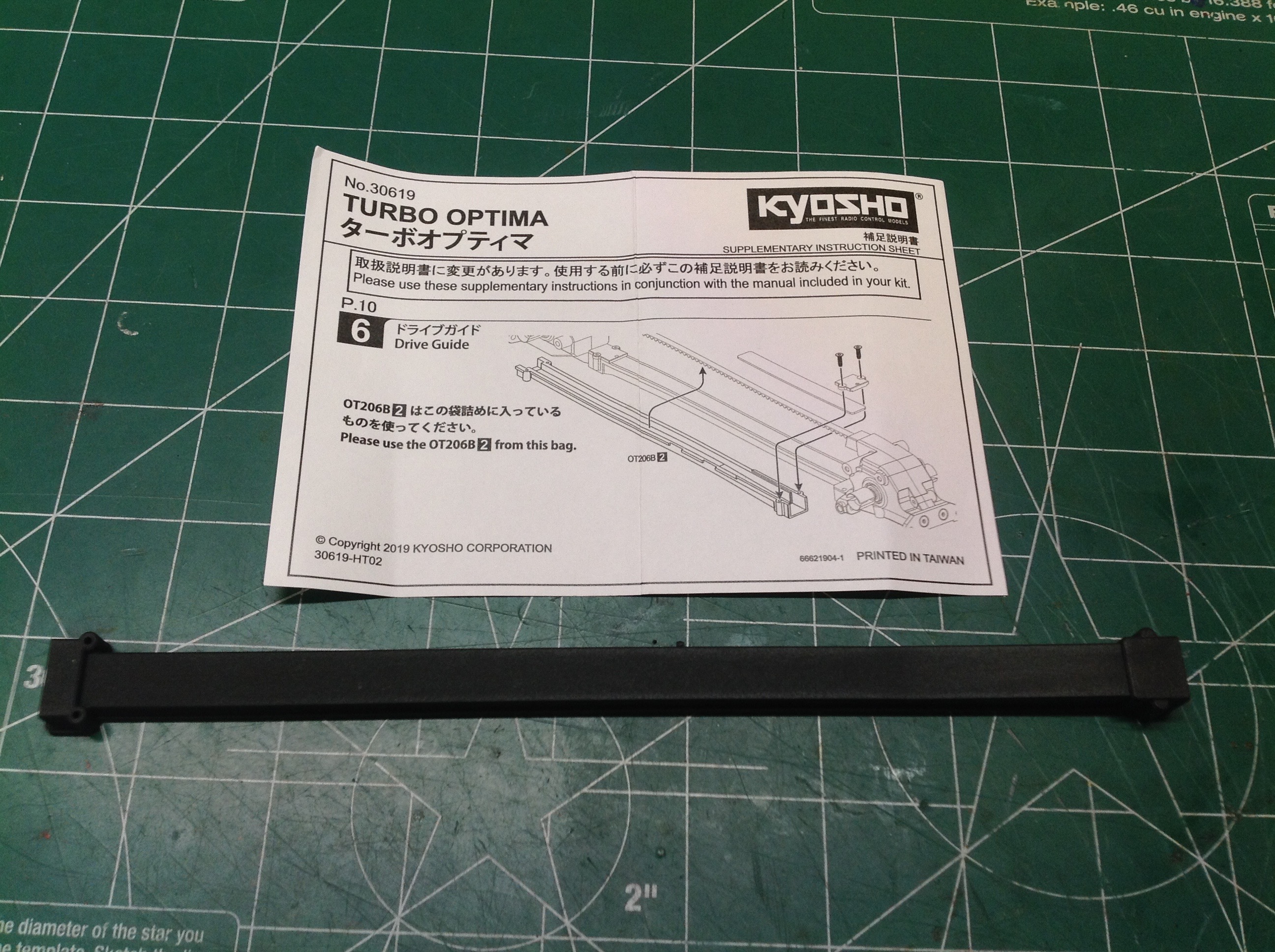
belt. The right hand image shows a part which was bagged
separately, apparently as a last minute replacement for the upper belt
guard. I studied it thoroughly for quite some time and can't find
any difference between it and the one that came stock in the box.
It is possible that a couple of tiny screw holes in the back have gotten
smaller, perhaps to make the screws grip more tightly.
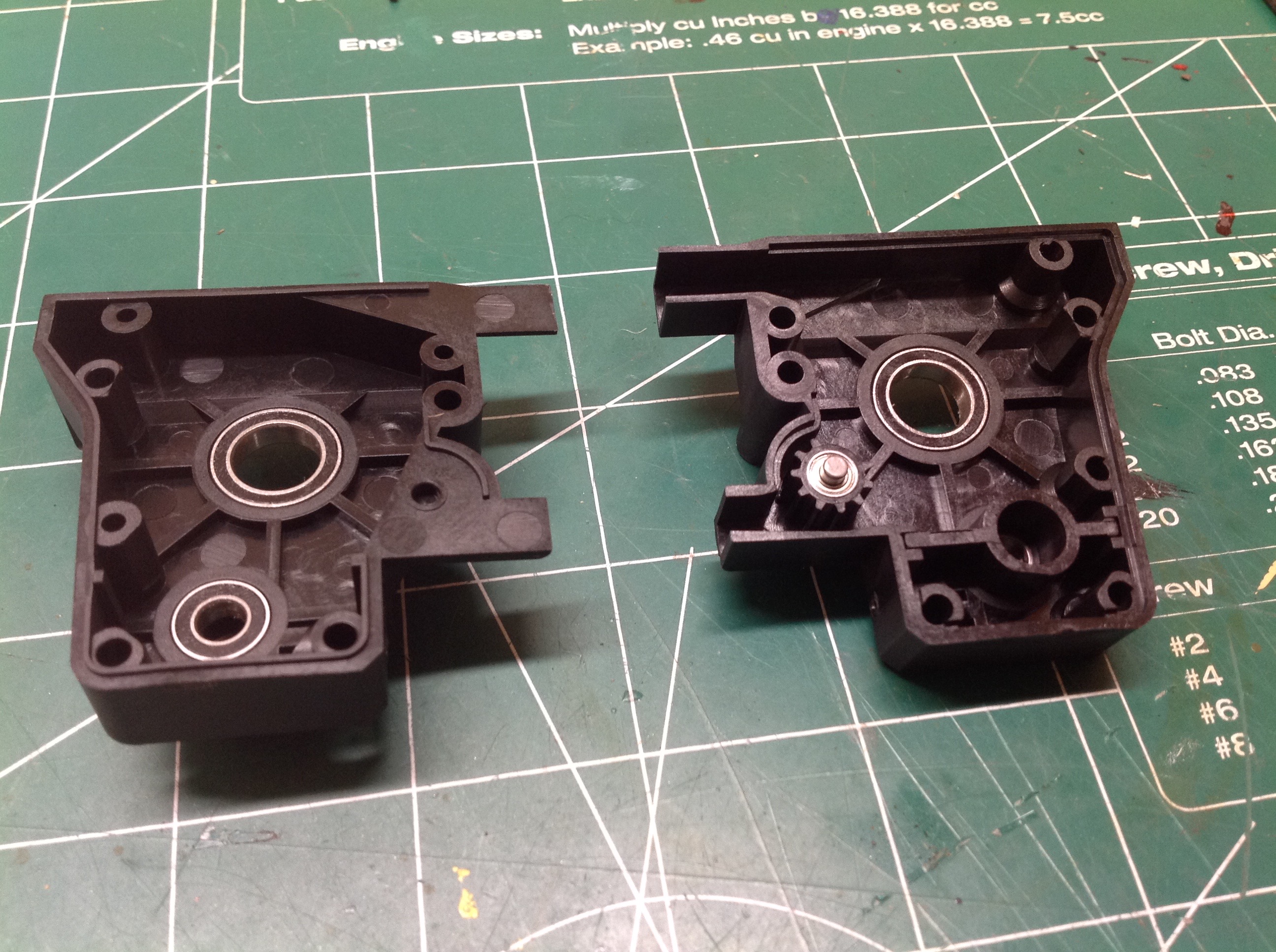
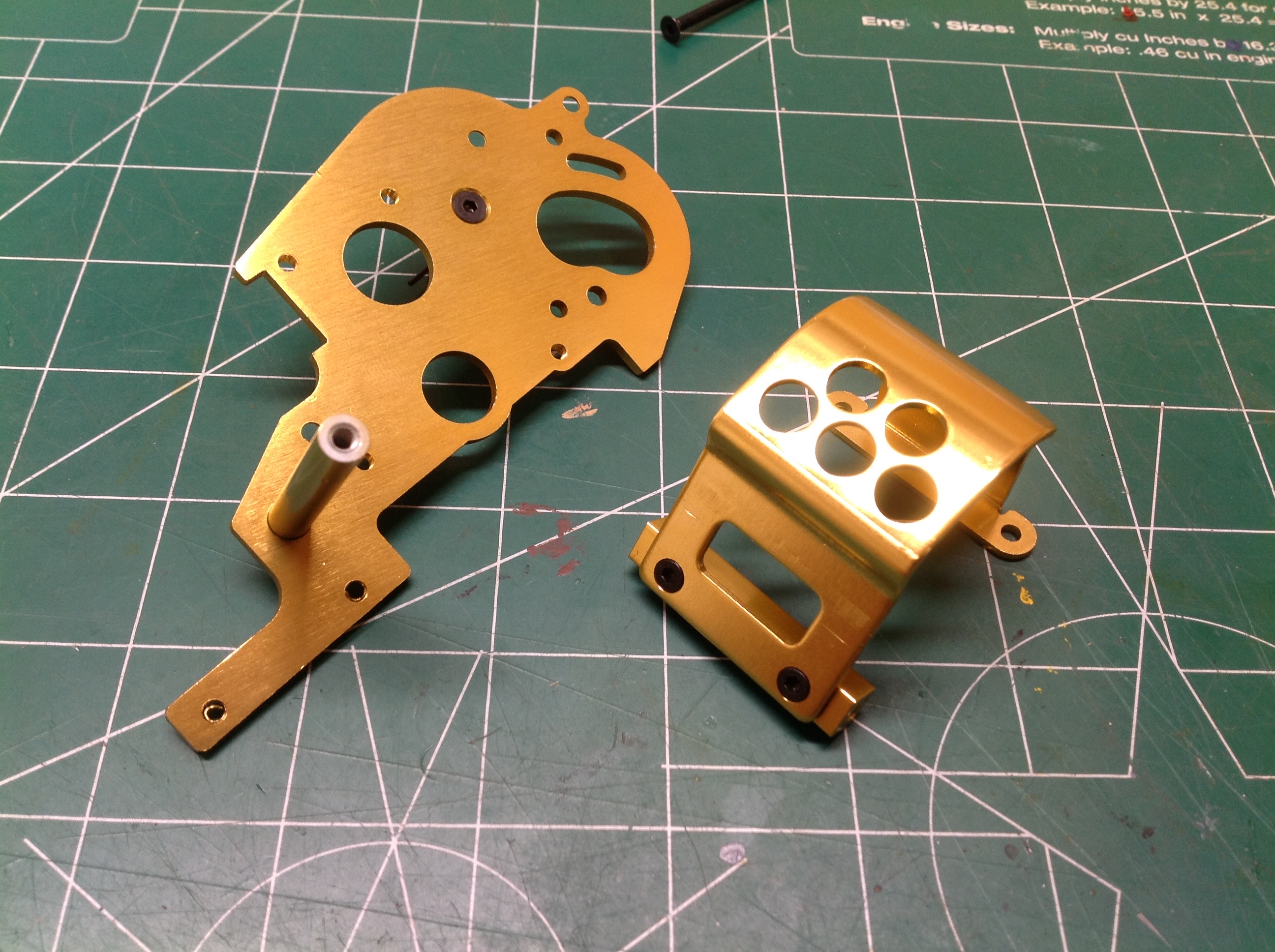
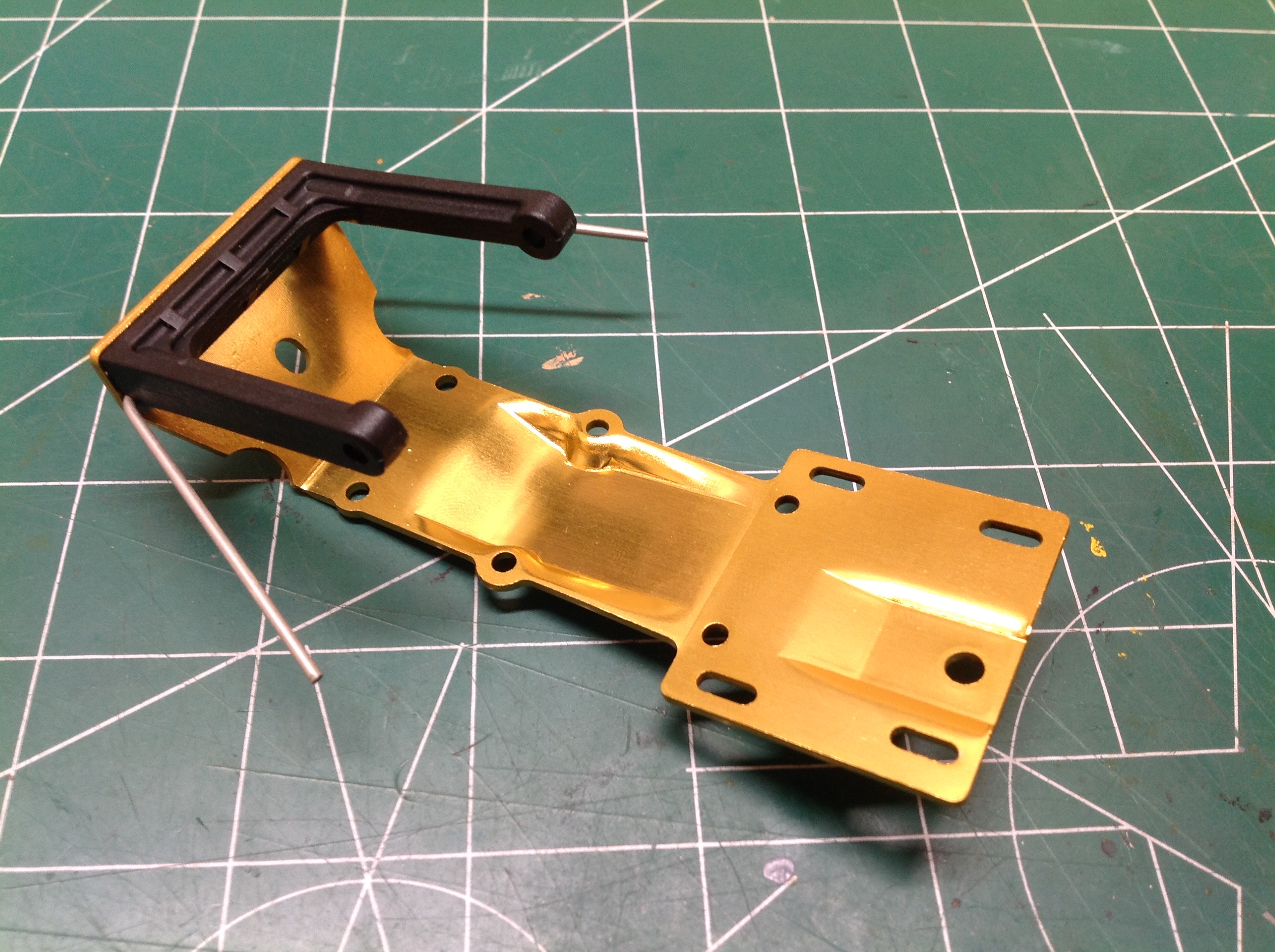
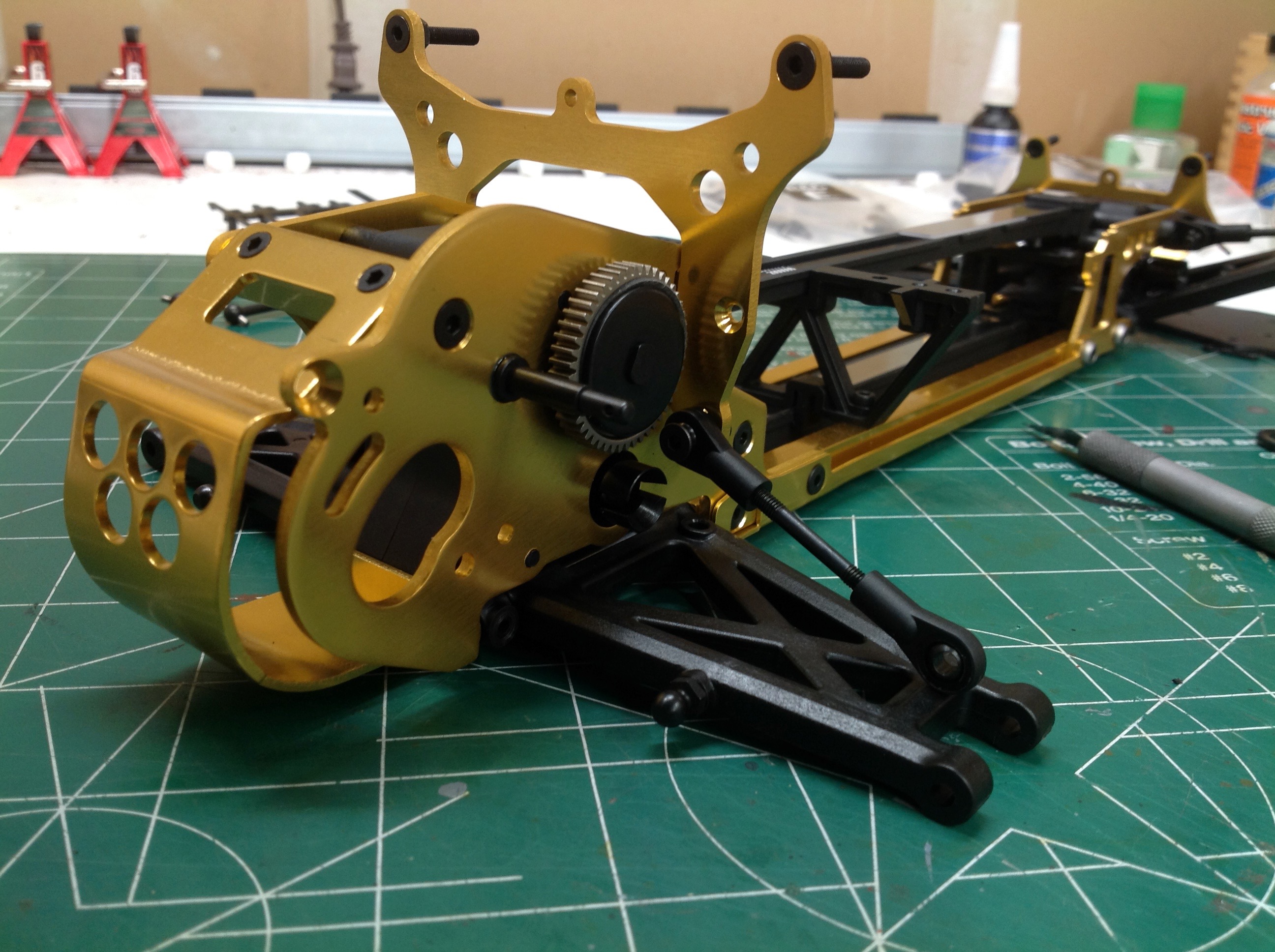
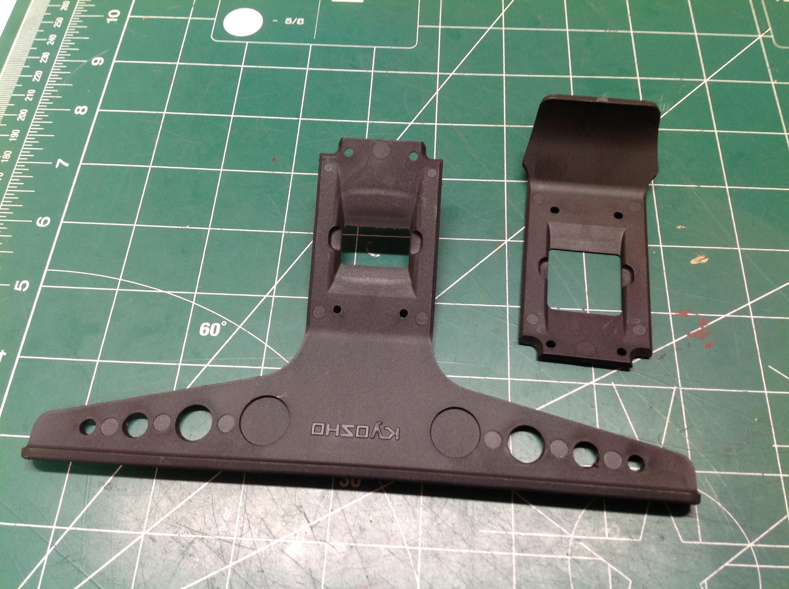
These parts are for the rear gearbox and form the major part of the
structure of the back of the chassis. The curved part with holes
is the motor shroud and presumably the vents are for cooling. The
large flat plate is the motor mount and right hand rear gearbox
attachment. The pin you can see sticking out of it does not spin,
it is a support for an idler gear.
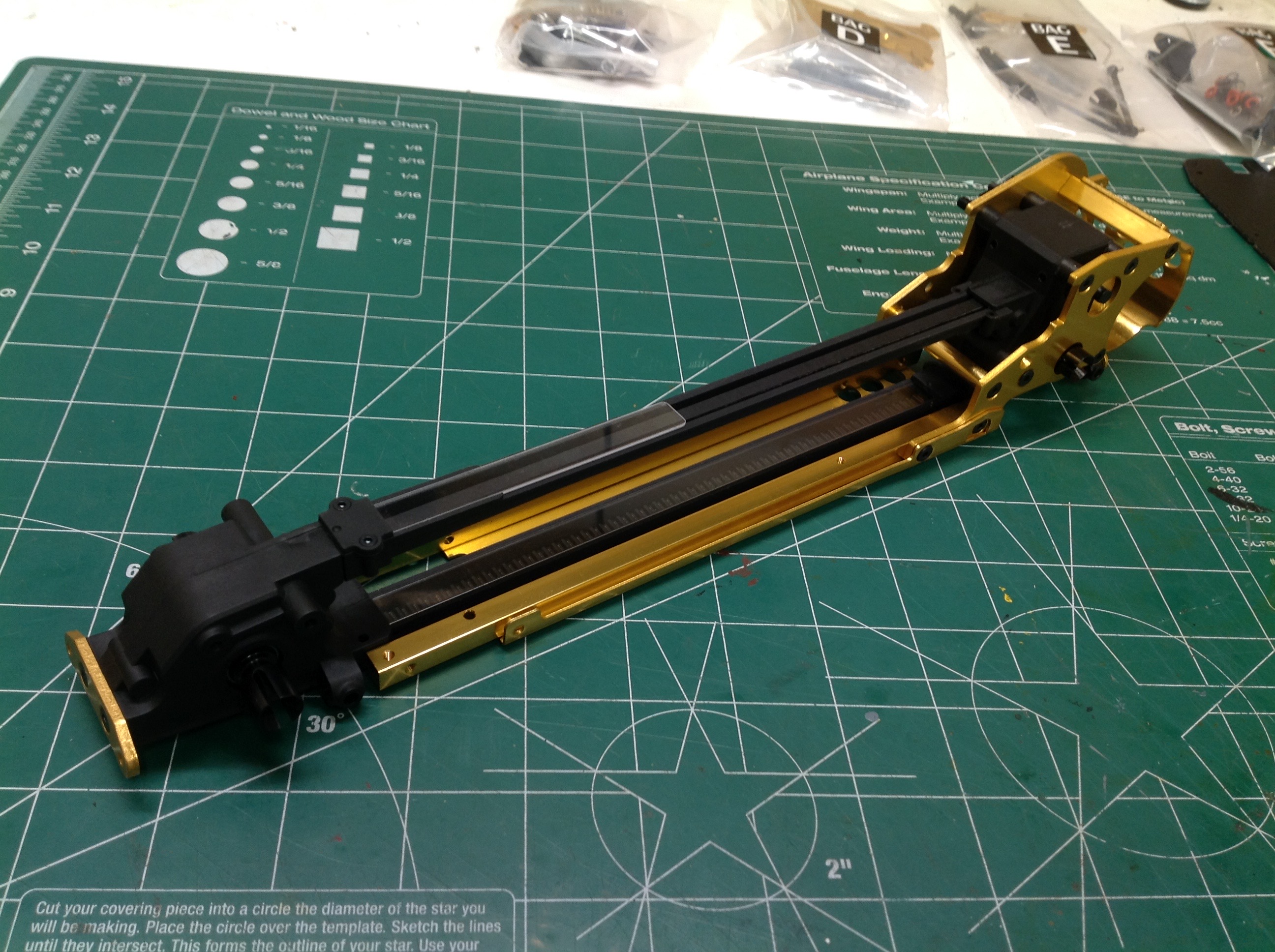
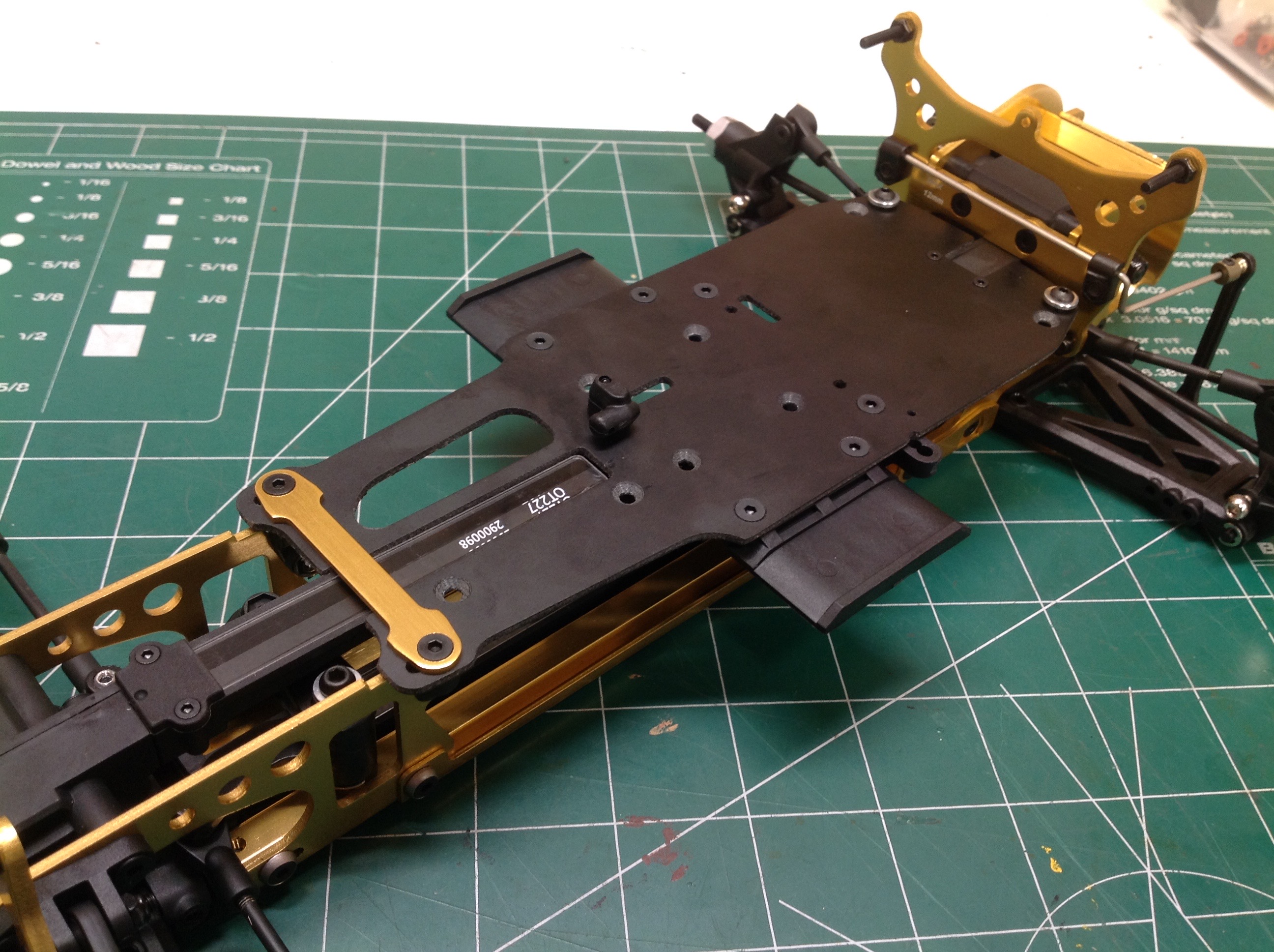
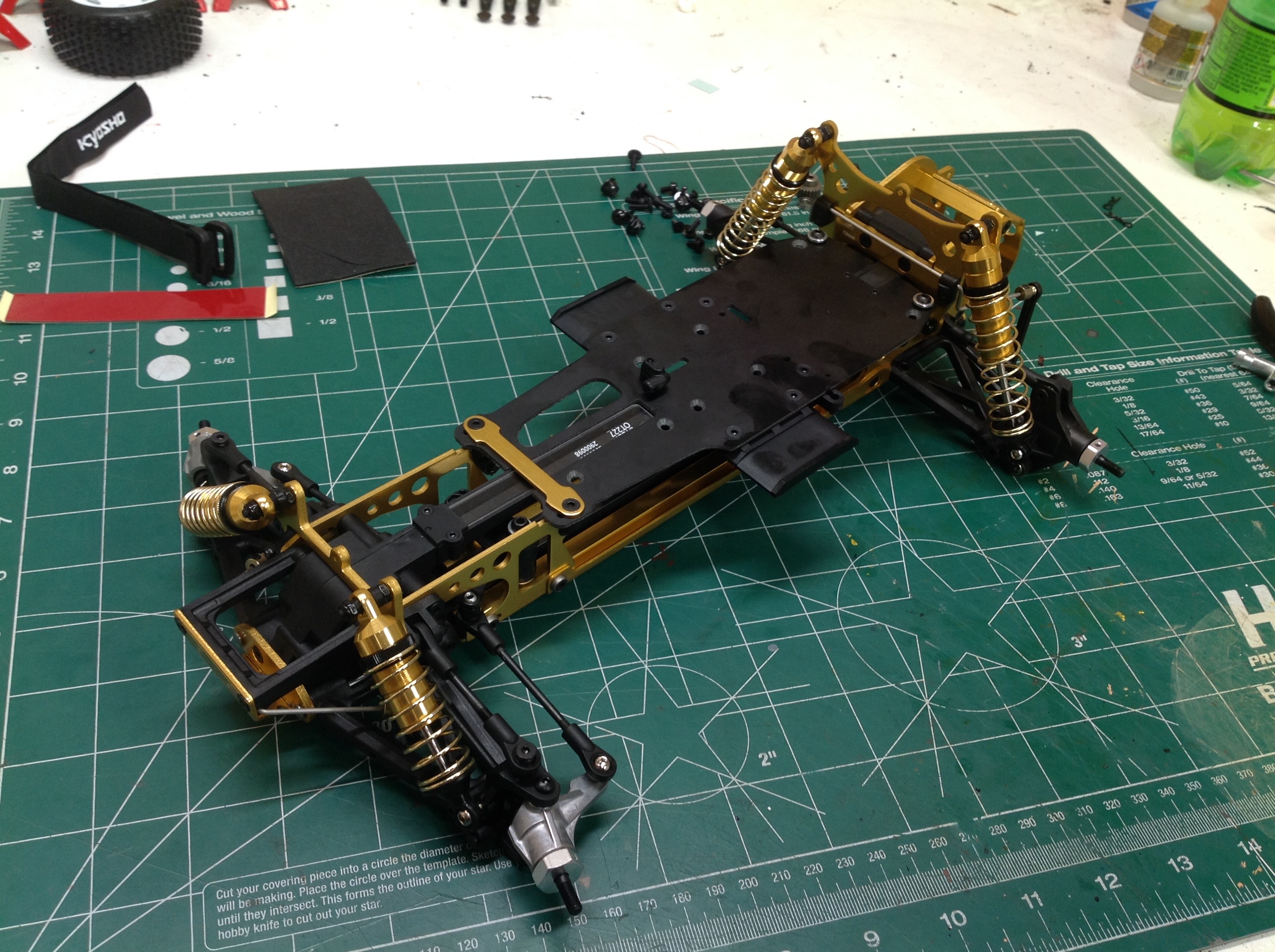
Now the undertray has been installed along with the longitudinal chassis
rails. The rails are intended to carry all the load (in fact the
Javelin doesn't even have the undertray) and the tray is there to keep
debris out. Protective undertrays tend to be polycarbonate, so the
fact that this one is formed aluminum is impressive.
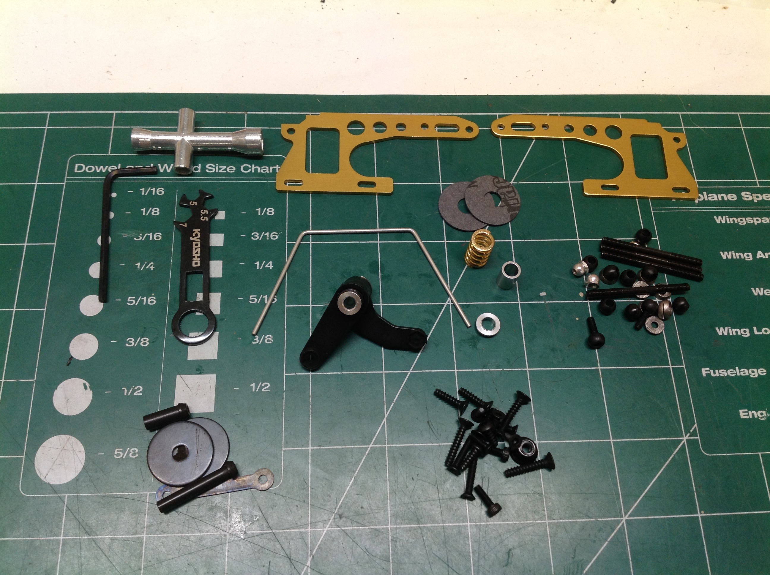
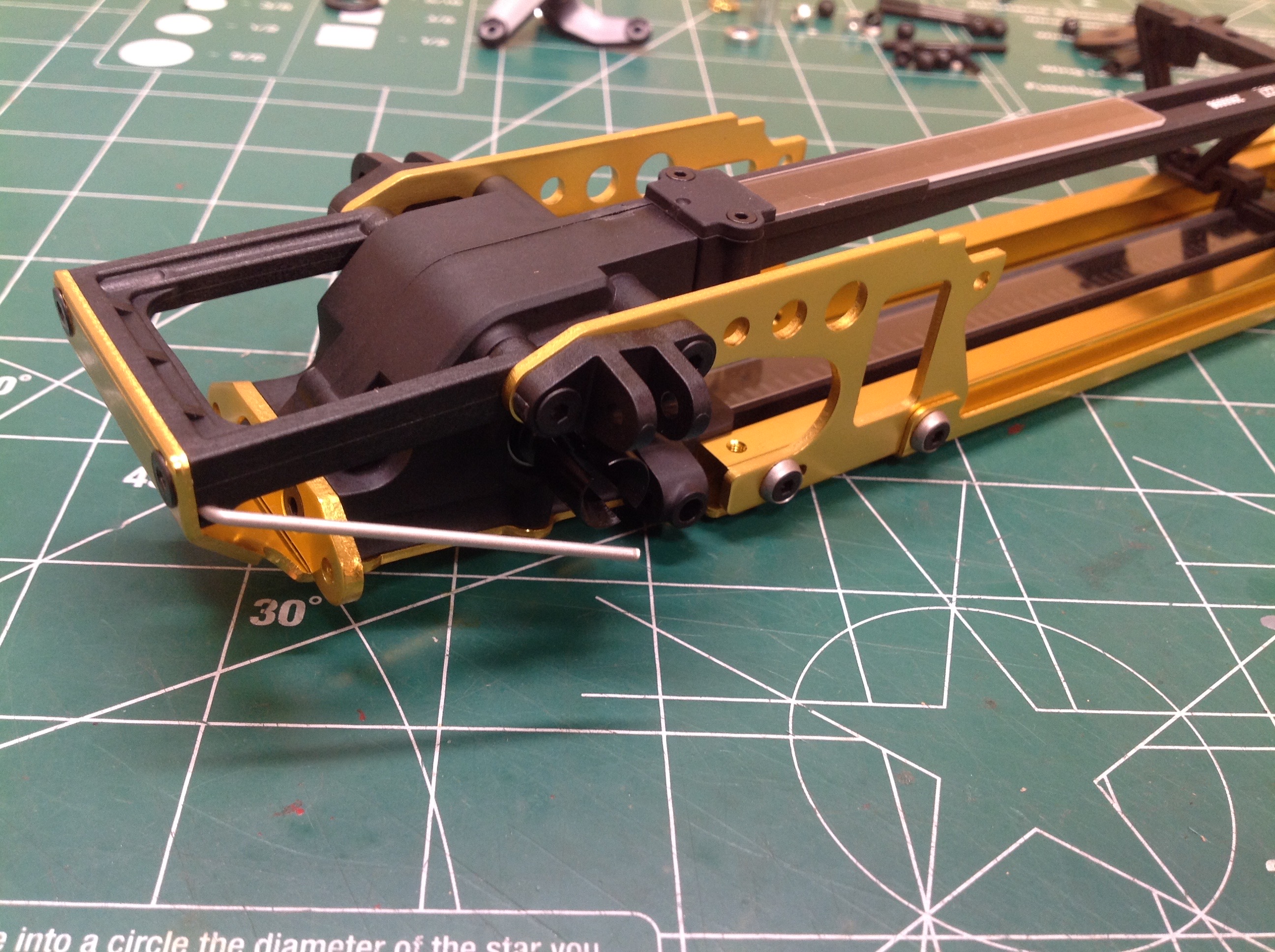
Time to open Bag C which contains gold supports for the front bulkhead,
steering, and suspension support parts. The first thing to build
is the front skid plate as shown. This protects the underside of
the front gearbox and serves to lift the chassis over any obstacle that
makes it between the tires. However, the front bumper will later
extend even under this, protecting it from scratches. The slots
you see in the bottom are to slide the whole front end to adjust belt
tension.
Here the skid plate has been installed along with the side supports for
the front gearbox. You can also see the upper suspension arm
supports if you look closely. The front sway bar pivots right at
the front of the chassis.
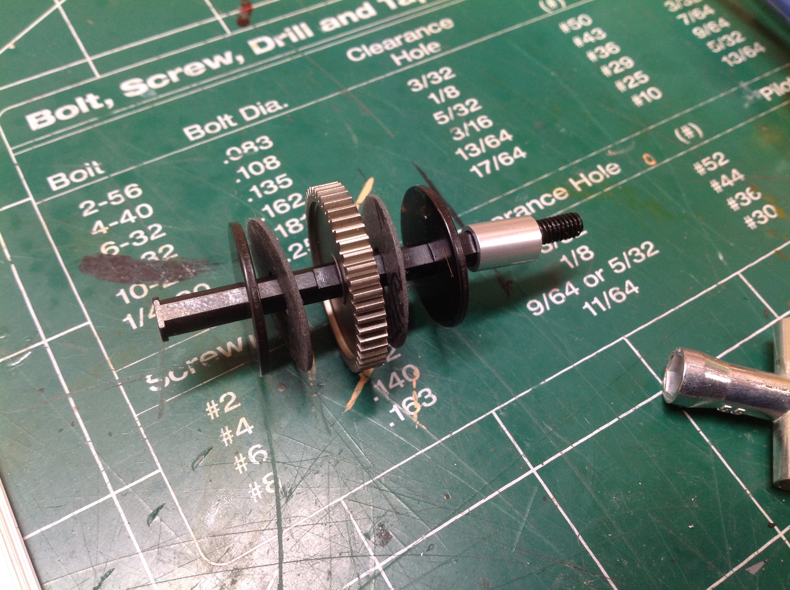
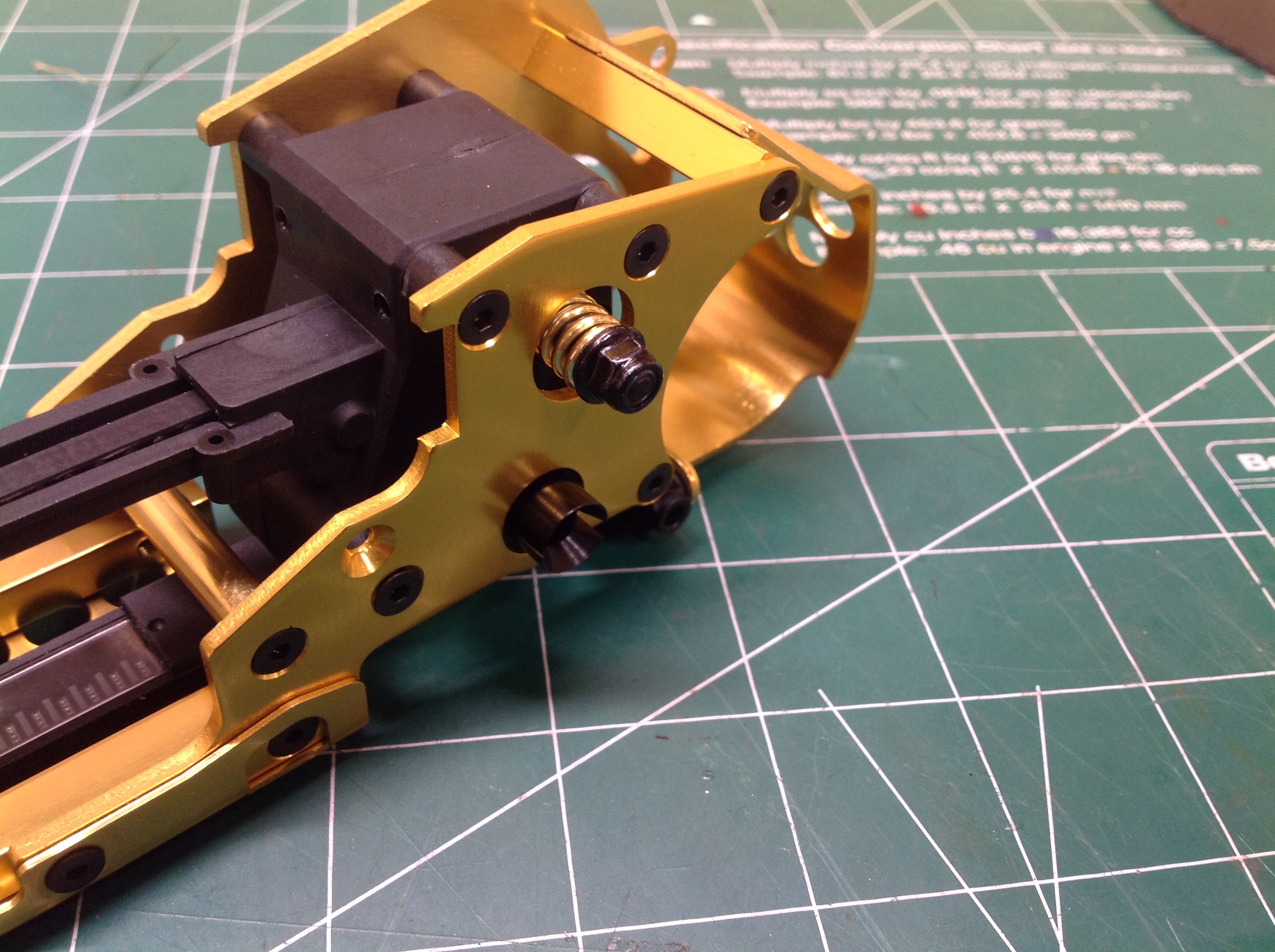
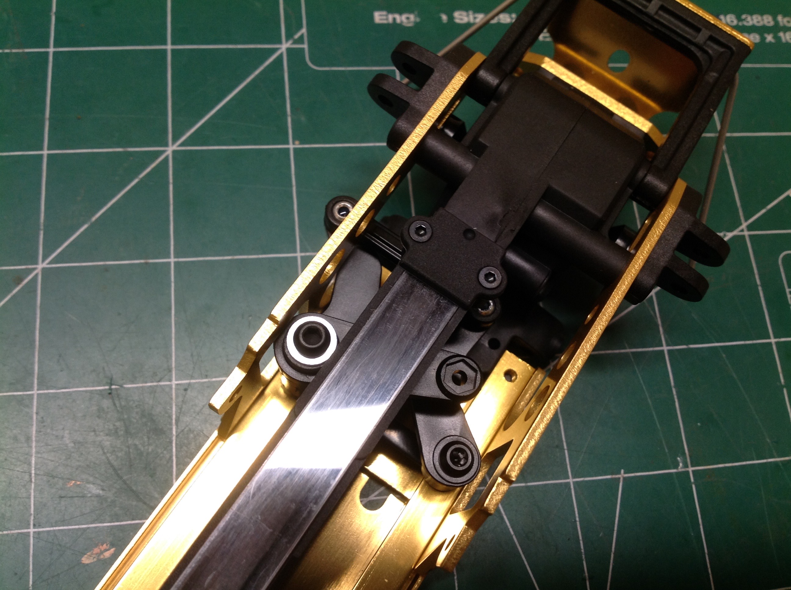
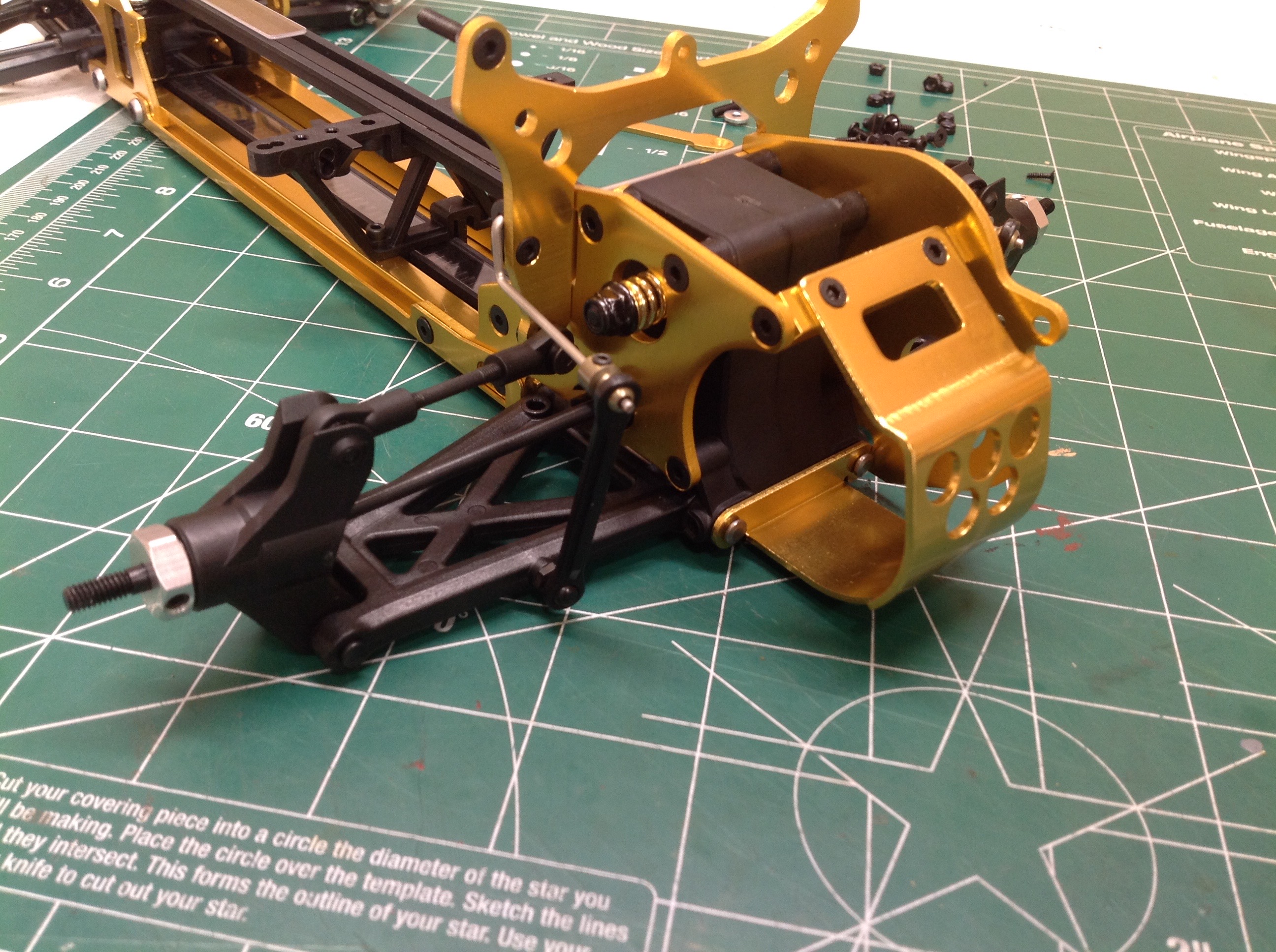
The slipper clutch is pretty conventional although it may have been a
bit of a novelty at the time. It uses a slipper pad (essentially a
brake disc) on either side of the spur gear. The slipped plate is
keyed to the flats on the shaft, but the gear is not. This allows
the gear to spin freely unless there is enough clamping across the pads
to produce adequate friction to transmit torque into the plates.
The compression spring used to adjust preload is actually installed on
the opposite side of the gearbox which I like because it reduces how far
the adjustment nut needs to hang out from the chassis.
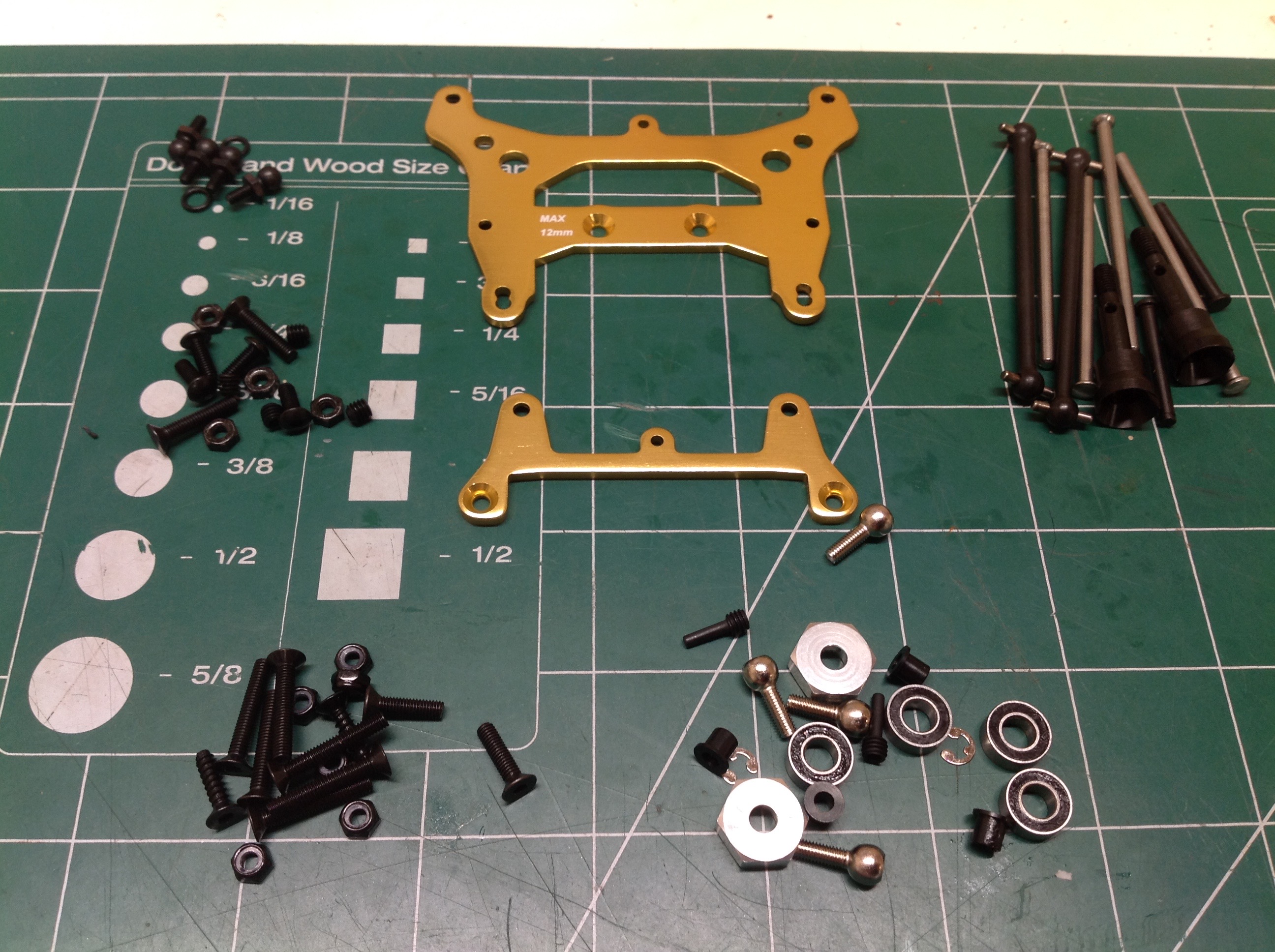
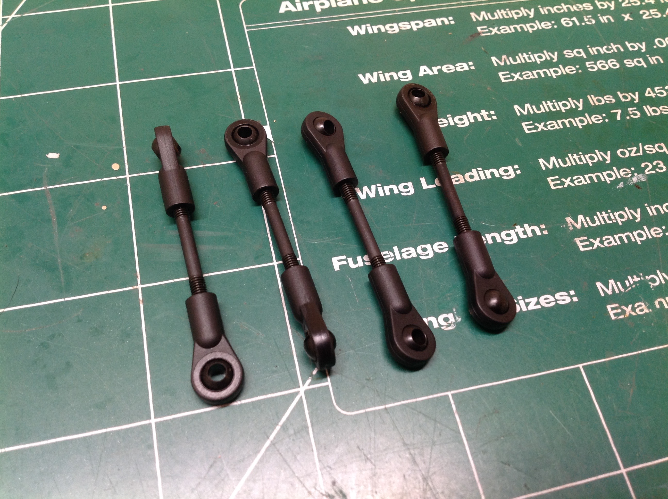
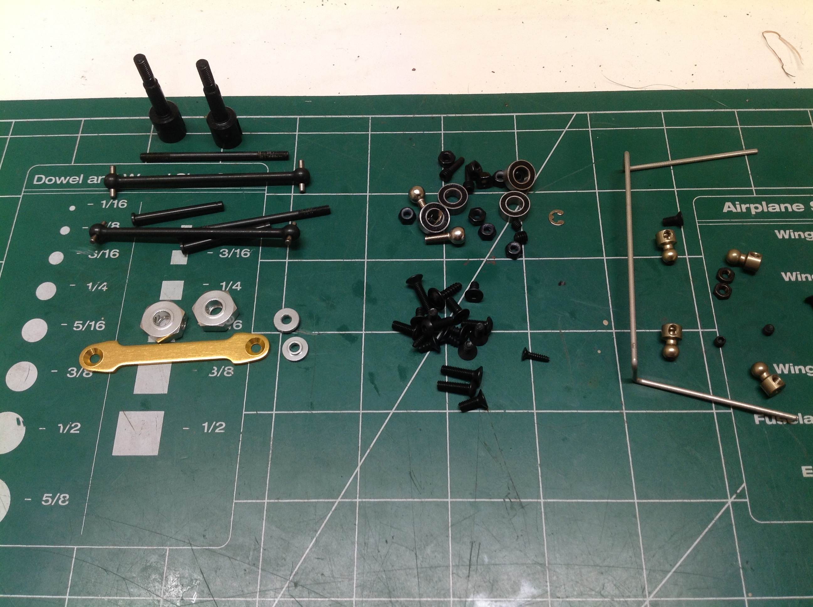
Bag D contains the parts for the front suspension and both shock
towers. I've built some links which will be used as upper
suspension arms and steering tie rods. The rod ends are plastic
but feel strong.
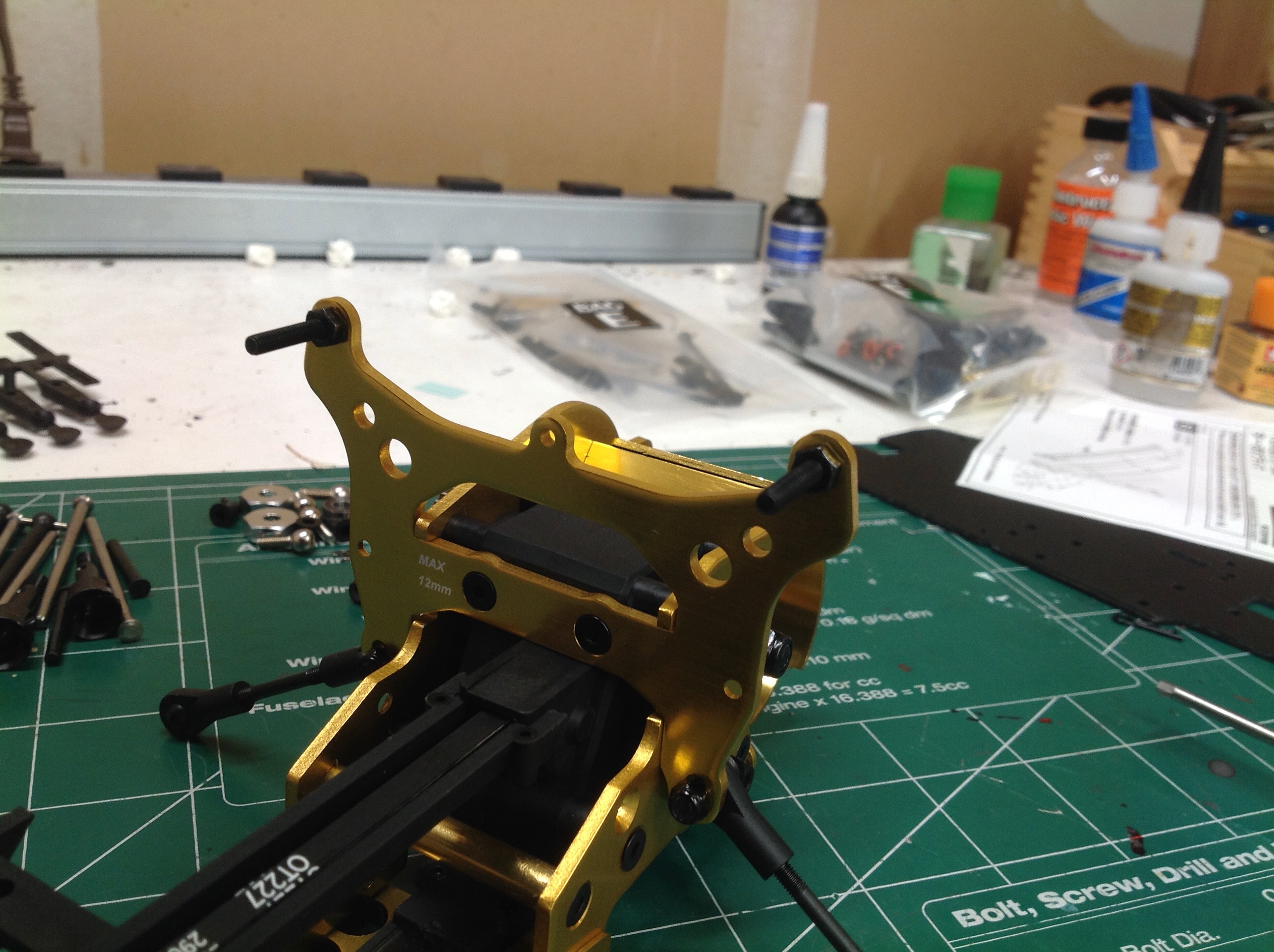
Here I've installed the front and rear shock towers which each consist
of flat anodized aluminum plate complete with holes and
countersinks. A close look at the rear shock tower will reveal a
note near one of the holes which says "MAX 12mm". Presumably this
is because using a longer screw here would cause it to poke inside the
gearbox and foul the differential. The shock supports are just
cantilevered screws which is not my favorite. I would much prefer
they were in double shear, but I'm sure this is adequate for the weight
of the buggy.
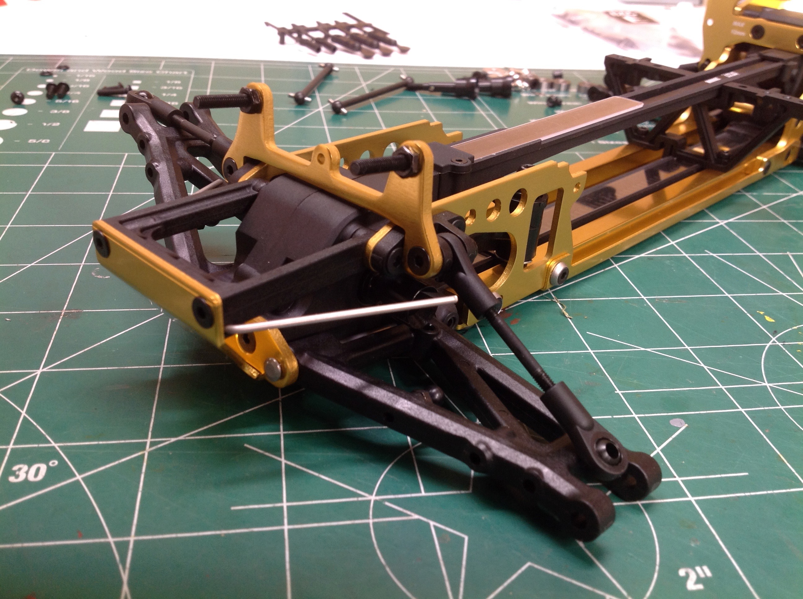
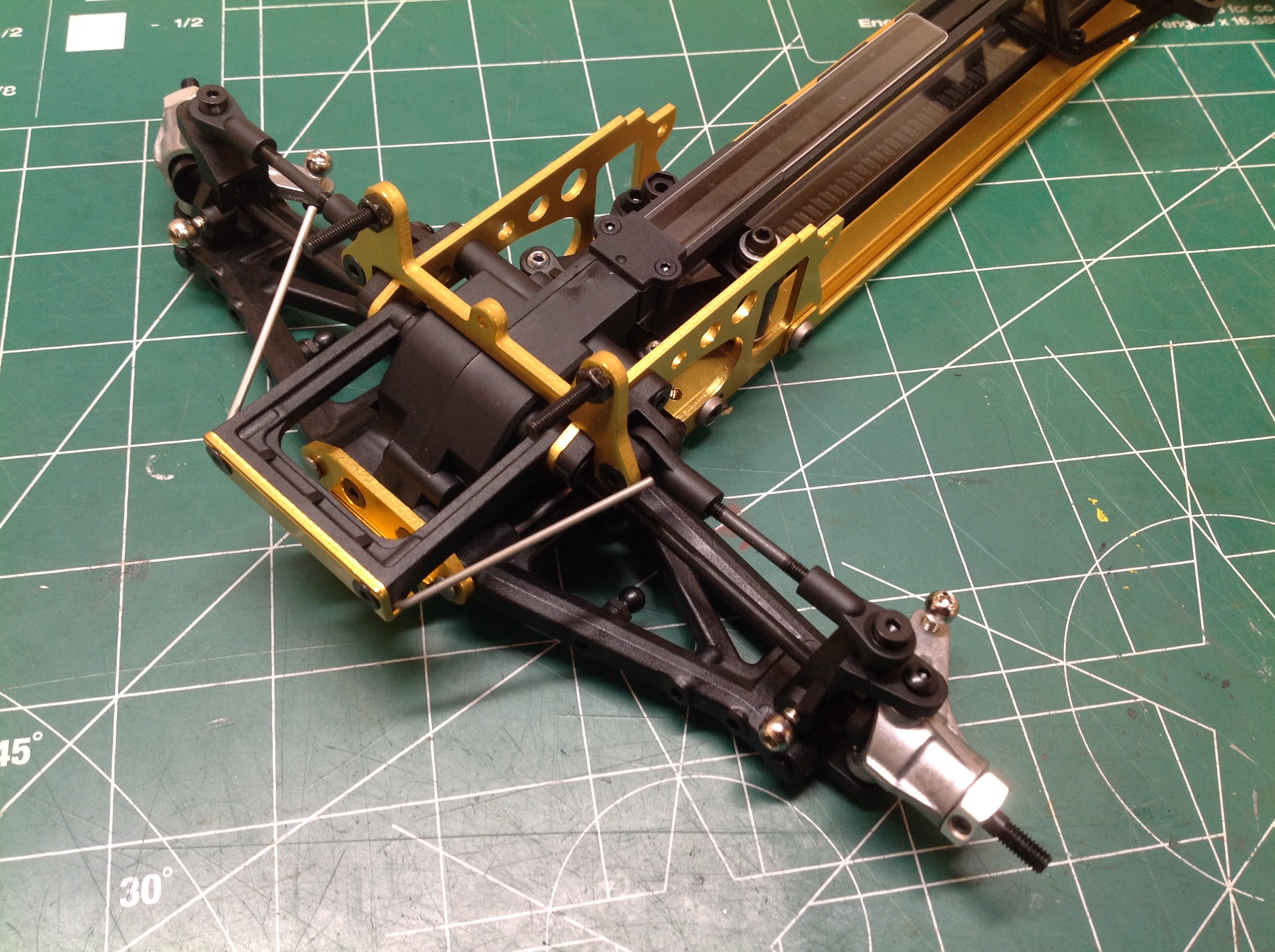
Now I've installed the lower suspension arms which are single piece
plastic molded parts with a significant amount of diagonal
bracing. The upper arms are just rods which means the lower arms
need to carry all the thrust and braking forces. In the left hand
image you also get a clear view of the installed slipper clutch.
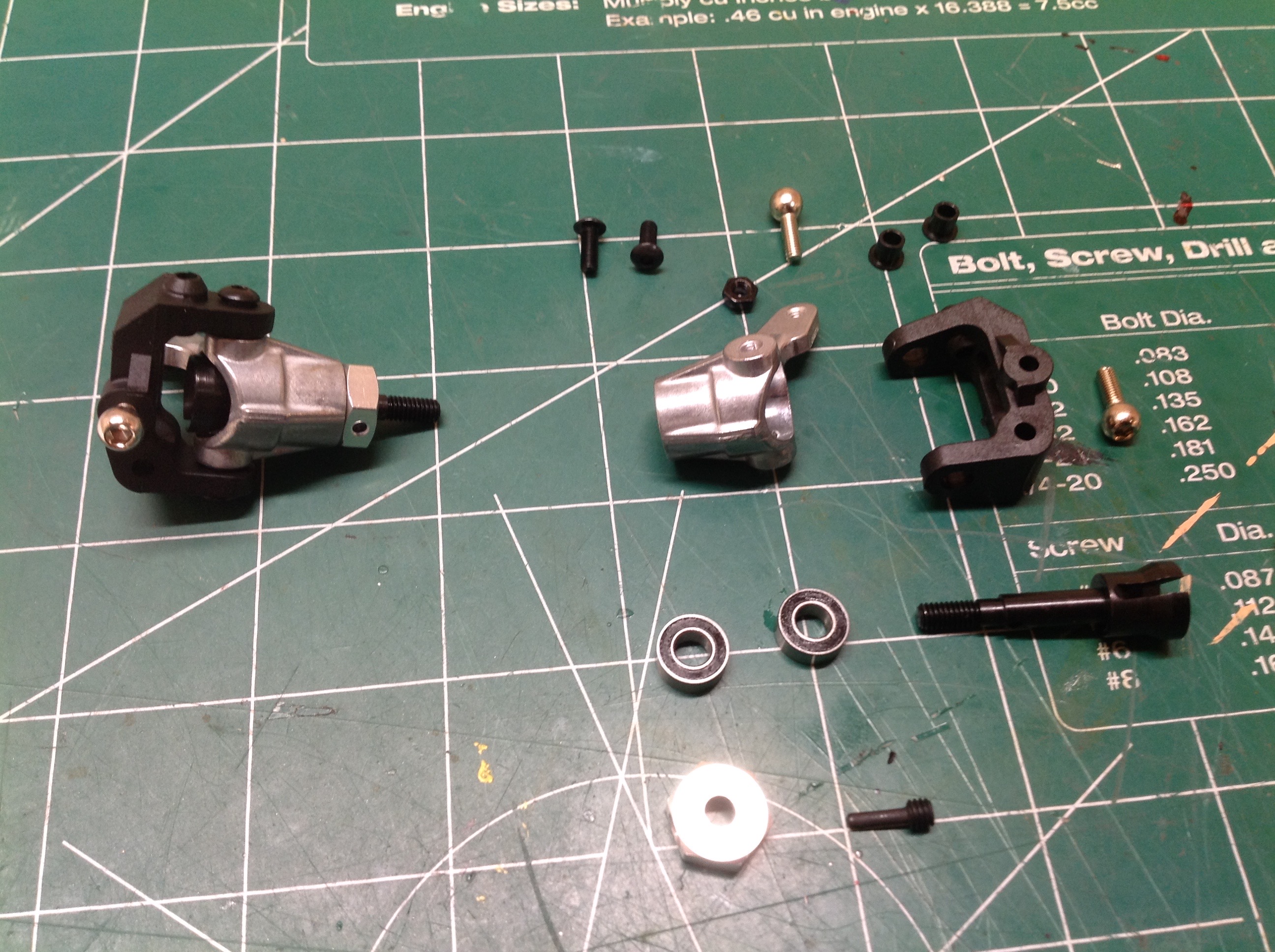
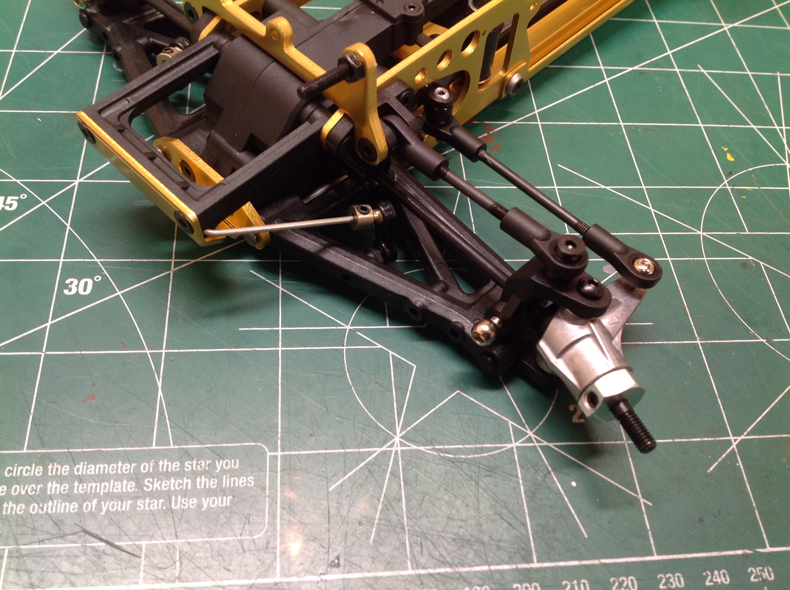
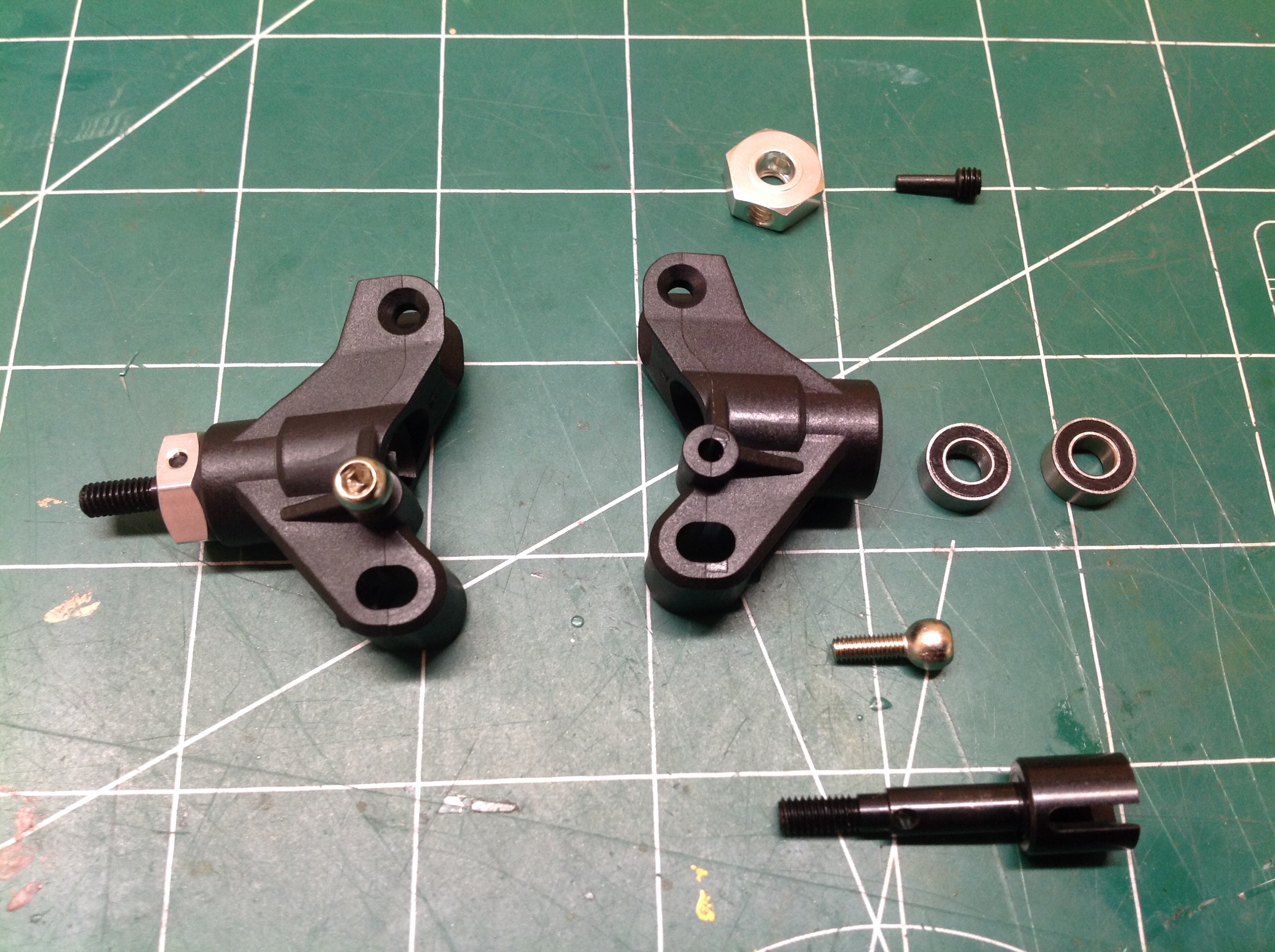
The steering is fun to build. The system uses C-hubs to support
the steering knuckles and kingpins. The bearings and drive cups
and housed within the knuckles. The knuckles are metal and appear
to be die castings. The right hand image shows them
installed. They aren't gold like the rest of the aluminum parts,
but they still stand out from the black plastic.
From above you can just barely see how the steering works. The
dual bellcranks are under the upper belt guard and supported only at the
bottom. The servo saver is built into the left hand crank.
The right hand image shows the steering tie rods attached and the sway
bar links as well.
Bag E has the parts for the rear suspension which don't look like much
because the main parts are plastic and on separate trees. Note the
complicated geometry of the sway bar.
The lower oblong holes in the rear uprights are for inserts which can be
swapped out to change the rear toe angle. By default the 2º toe
is used but parts are included for 1º and 0º. The rear sway bar
has also been attached here.
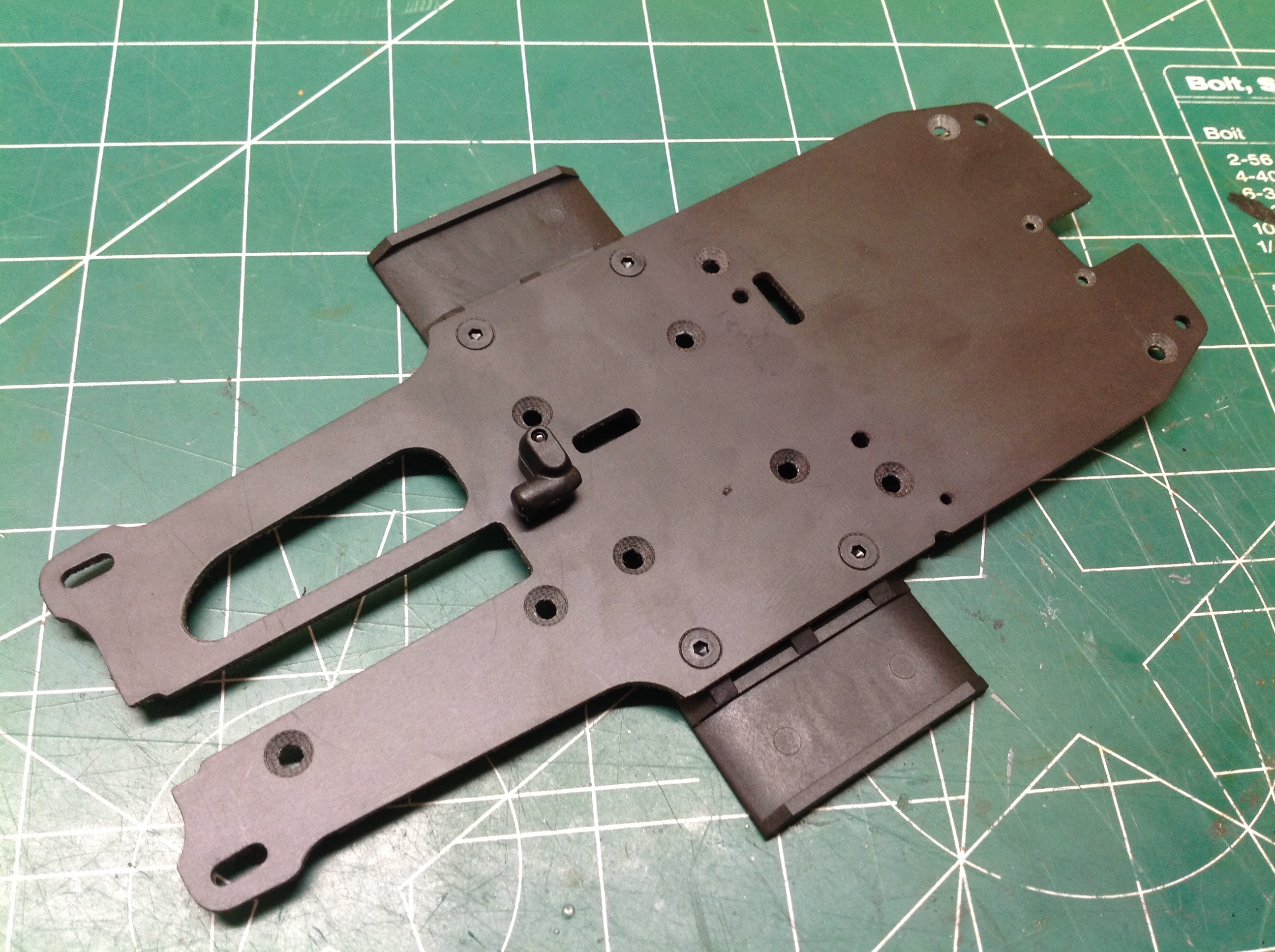
This plate is not carbon fiber but it looks pleasantly like it.
This upper plate stiffens the chassis and provides a mounting surface
for the receiver and ESC. The receiver sits on top and will be
hidden by the driver. The ESC adheres underneath. The
"wings" you see protruding are supports for the Velcro® straps which hold the battery.
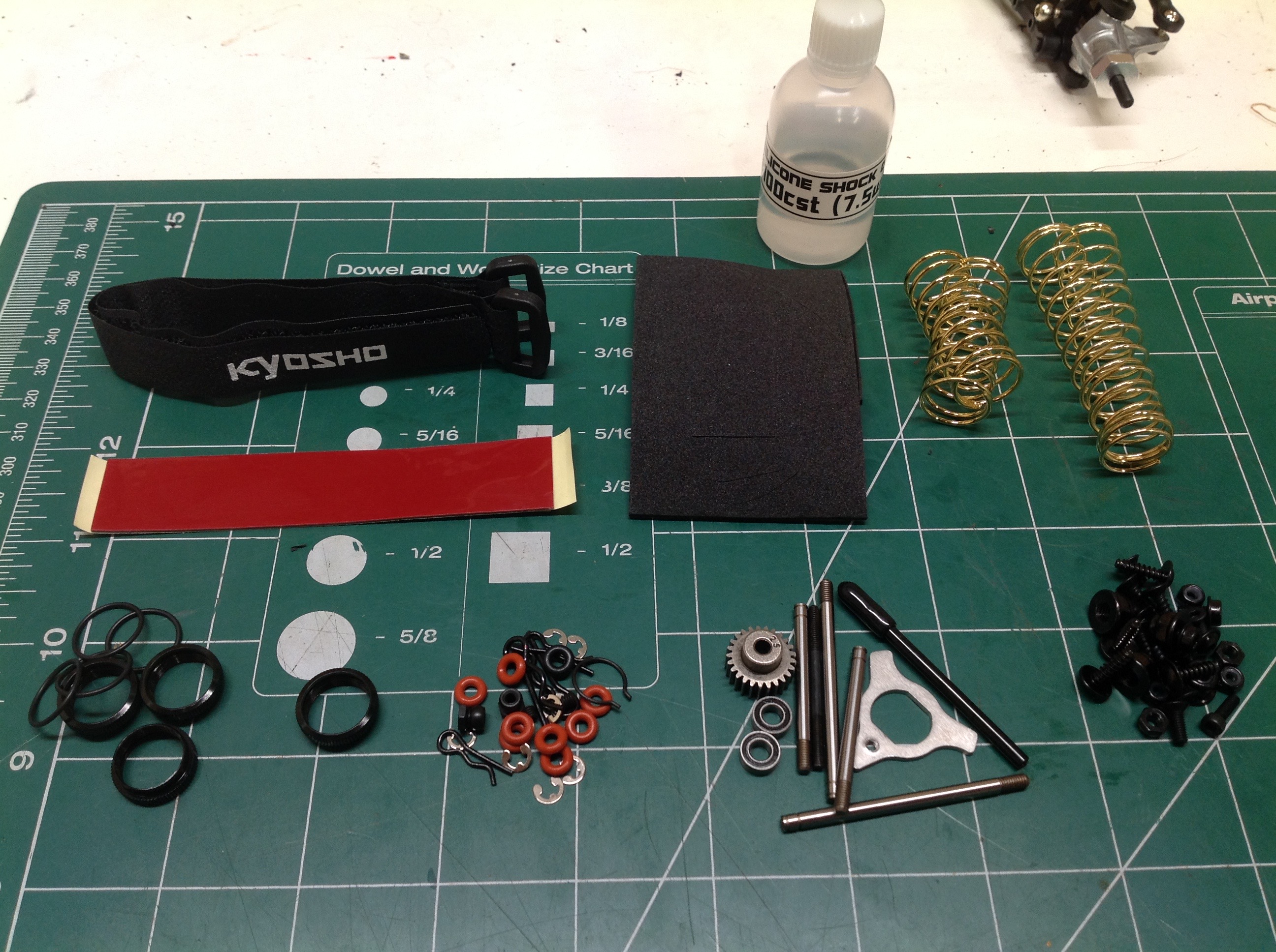
Finally we get to build those beautiful shocks with the parts from Bag
F. There are quite a lot of O-rings and other miscellaneous little
parts here. Even the springs are gold! Among the parts are
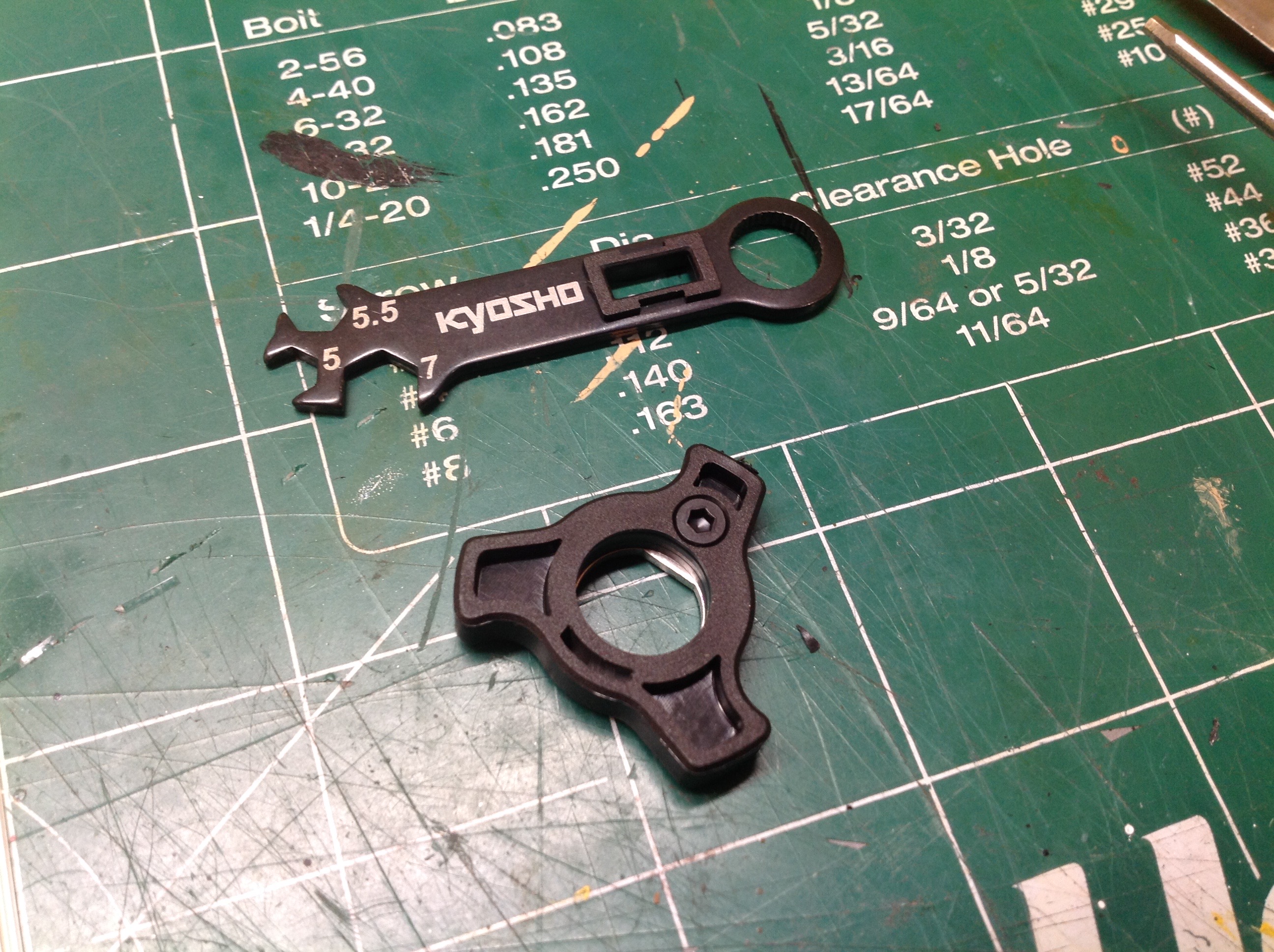
those needed to build the tools shown at the right which will assist
with assembly. The rectangular slot in the wrench fits over the
head end lug, and the Glaive shaped tool fits over the rod end
gland. With both tools you can effectively tighten the ends of the
cylinder.
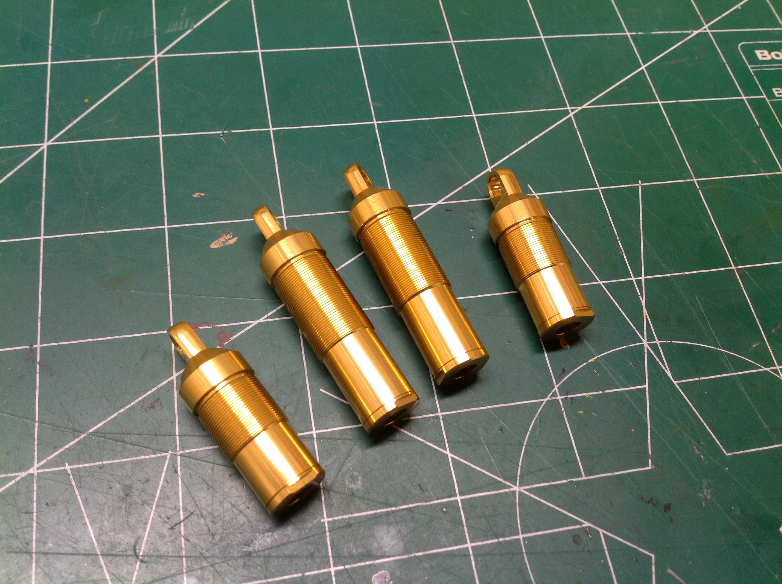
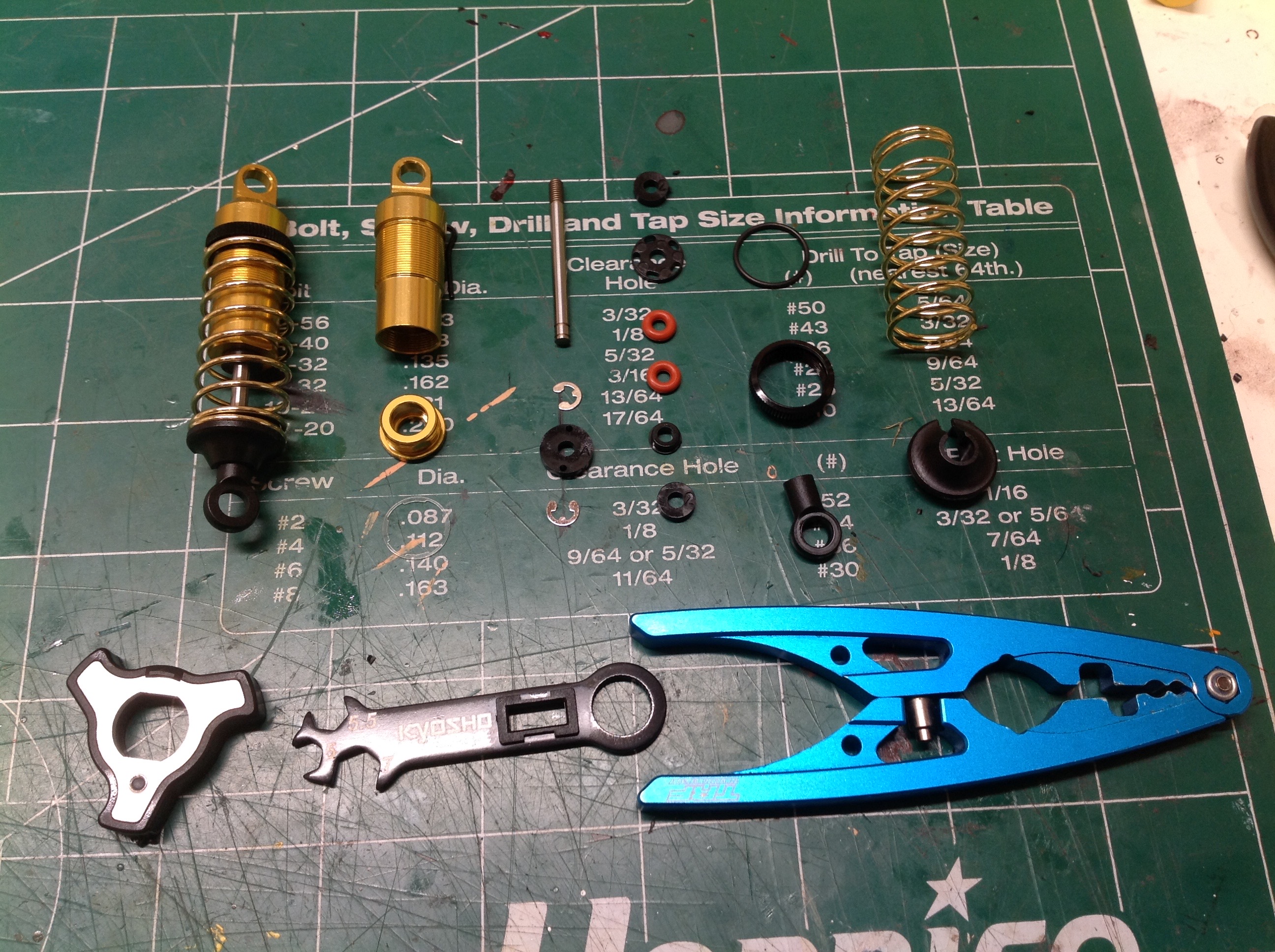
The aluminum parts of the shock consist of only two parts because the
head end plug is integral to the cylinder which must everything must be
inserted from the rod end. Note how much longer the rear shocks
are than the front. The picture on the right shows one completed
shock next to an exploded view making it clear just how many parts there
are. I count 18 parts per shock. The part you didn't see is
the almost invisible gasket sitting just beneath the rod end
gland. The front piston heads have 2 holes and the rear have
3. Each is retained by 2 E-clips. There are also a pair of
O-rings and a couple of rod guides inside each gland. Both front
and rear shocks have a spacer on the outside to limit compressed length,
and the front shock also has an internal spacer to limit extended
length. The threaded collar on the outside of the cylinder is used
to adjust spring preload (which controls ride height) and contains
another O-ring to add some friction to it doesn't vibrate an unthread
while driving. The shocks use very thin 7.5wt oil.
With the shocks installed, the chassis is nearly done. Other than
the electronics, it might not be obvious what is still missing at this
point.
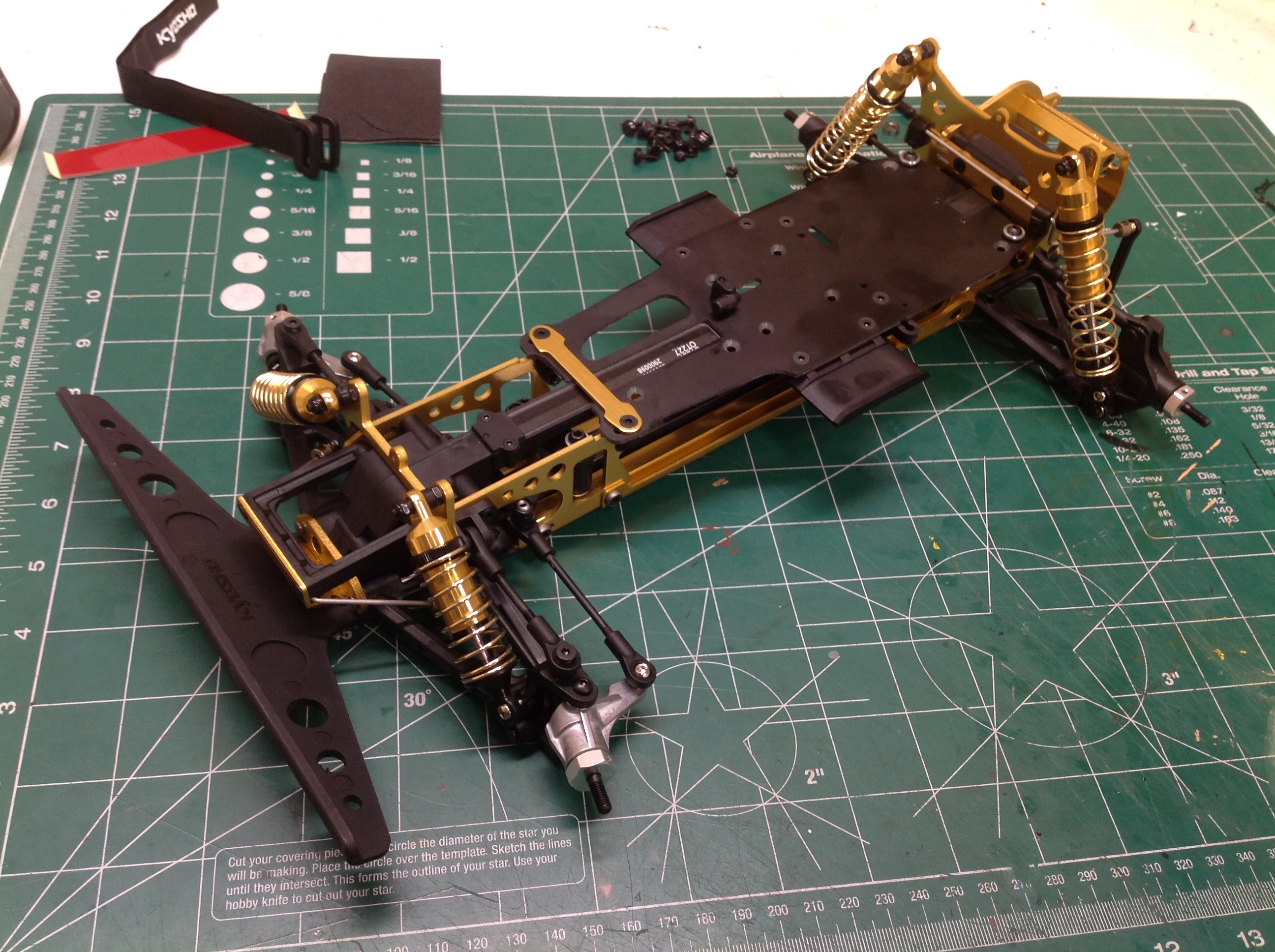
Time to install the rather substantial front bumper which will protect
the front tires from direct impact. It is well anchored to the
chassis and isn't coming loose any time soon.
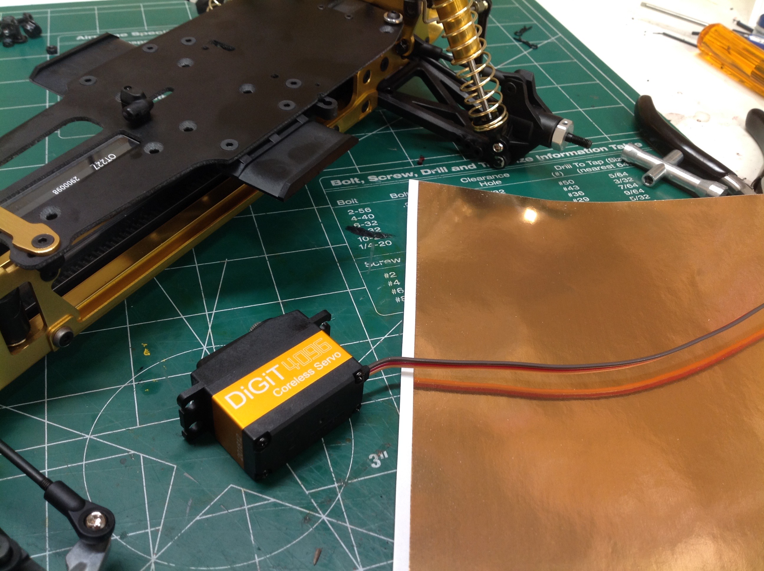
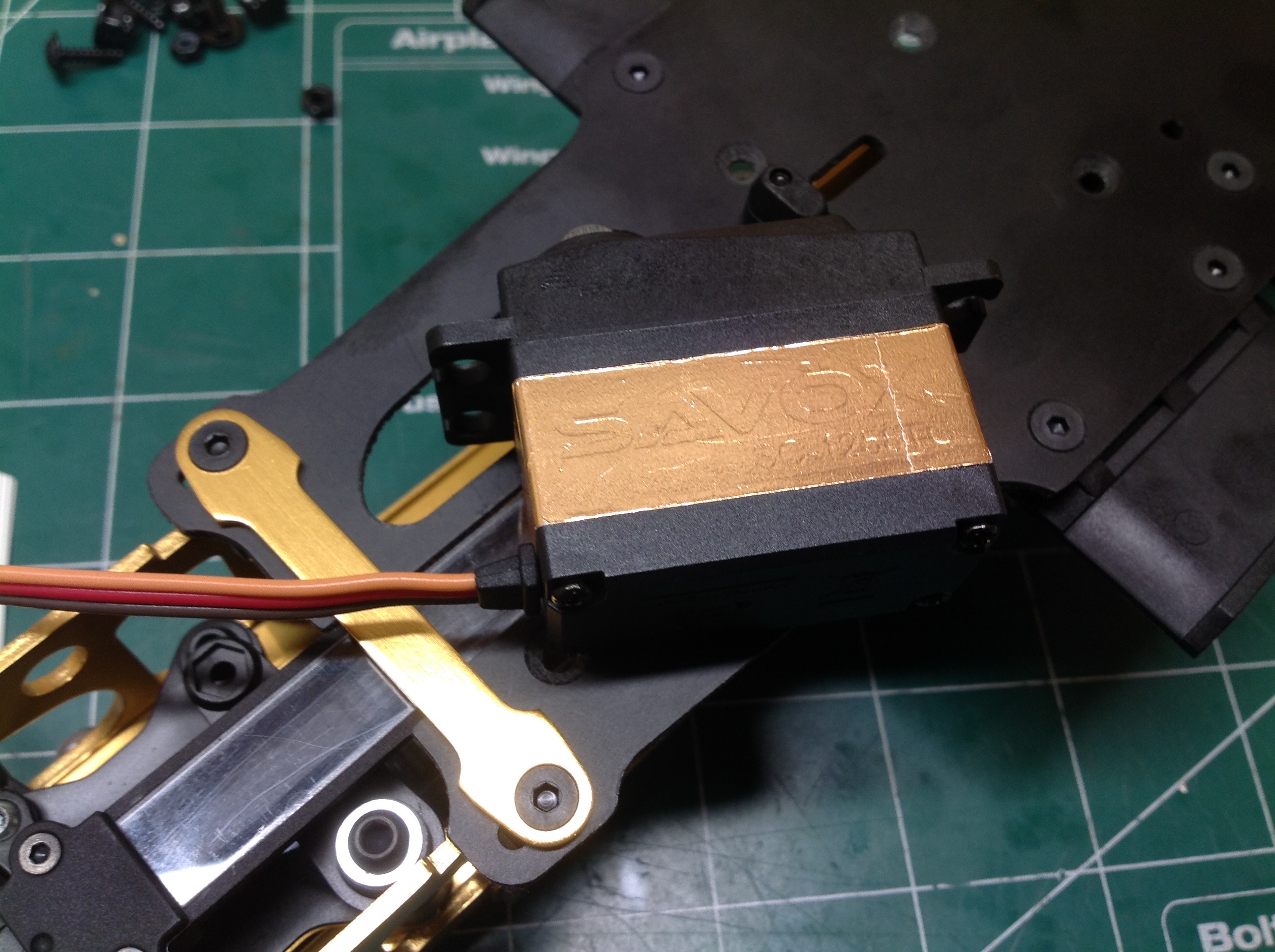
With the rolling chassis done, I can get started on the
electronics. A light buggy like this doesn't need a fancy or high
powered steering servo, but the model is just so pretty that I wanted
something special. I knew Savox servos use a nice orange aluminum
case which I was hoping would match the anodizing, but it didn't
quite. I bought a sheet of gold foil as shown on the left and used
it to wrap the metal part of the servo. To do this, I had to take
the servo apart, wrap the center portion, then put it back
together. The result on shown on the right which looks pretty
great if I do say so myself.
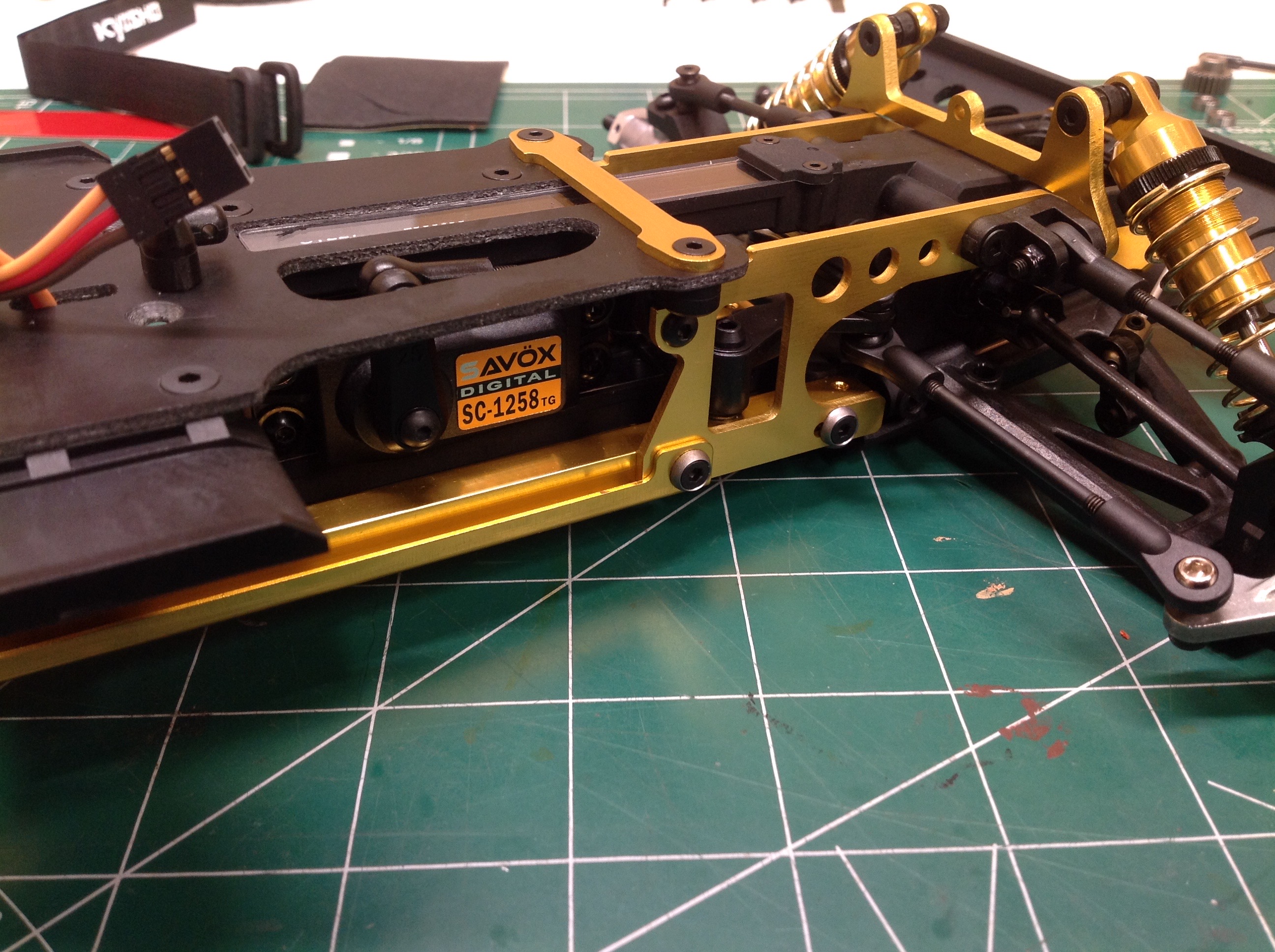
Much to my chagrin, it turns out you pretty much can't see the servo
case once it is installed in the chassis. Oh well, at least I know
it is in there. (Hard to justify that high dollar, titanium gear
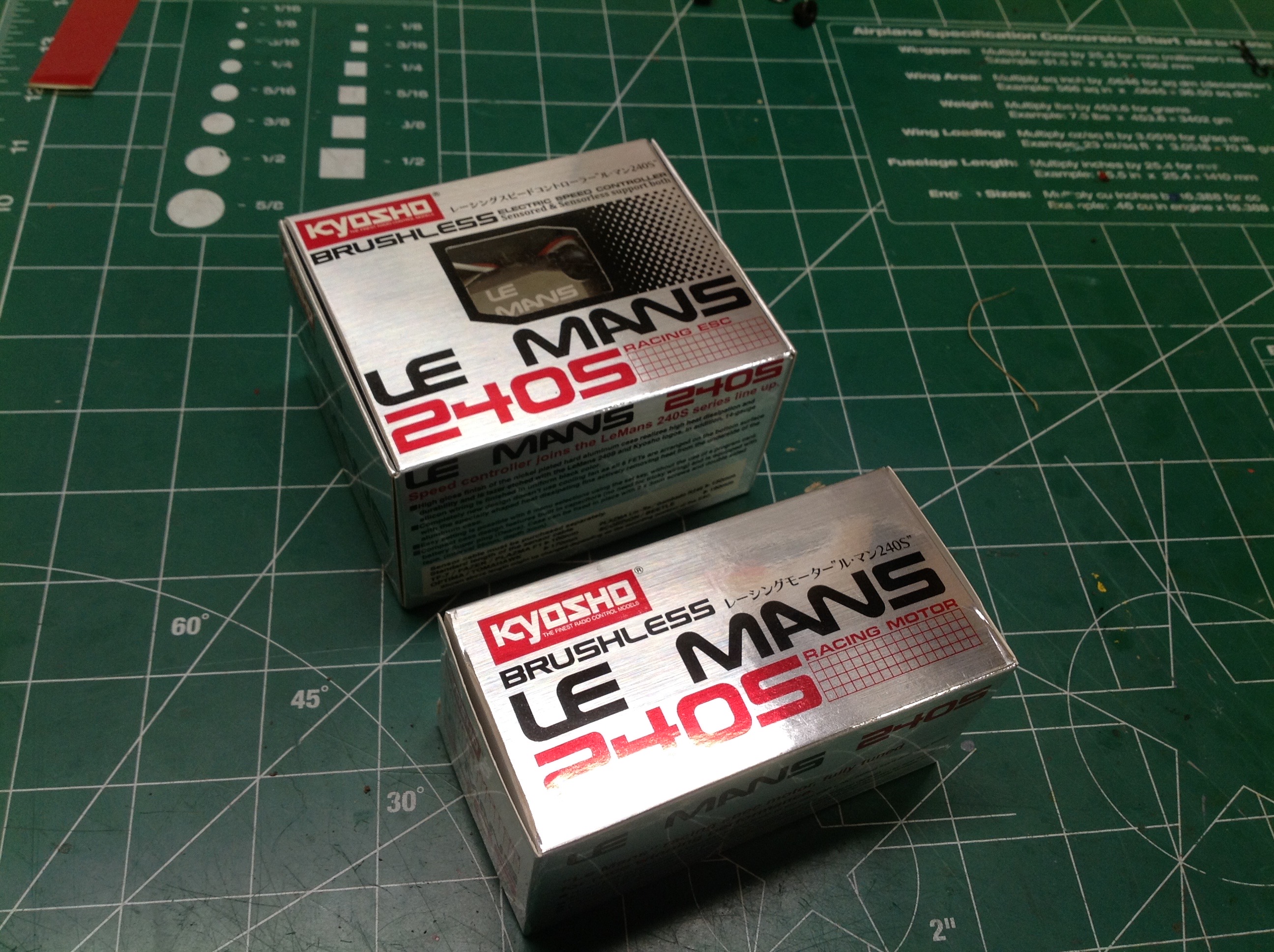
servo though.) On the right you can see the power system I got for
this model. I wanted a genuine Kyosho Le Mans system, but updated
for modern times like the buggy. This is a sensored brushless
motor and controller. Let's see what's inside.
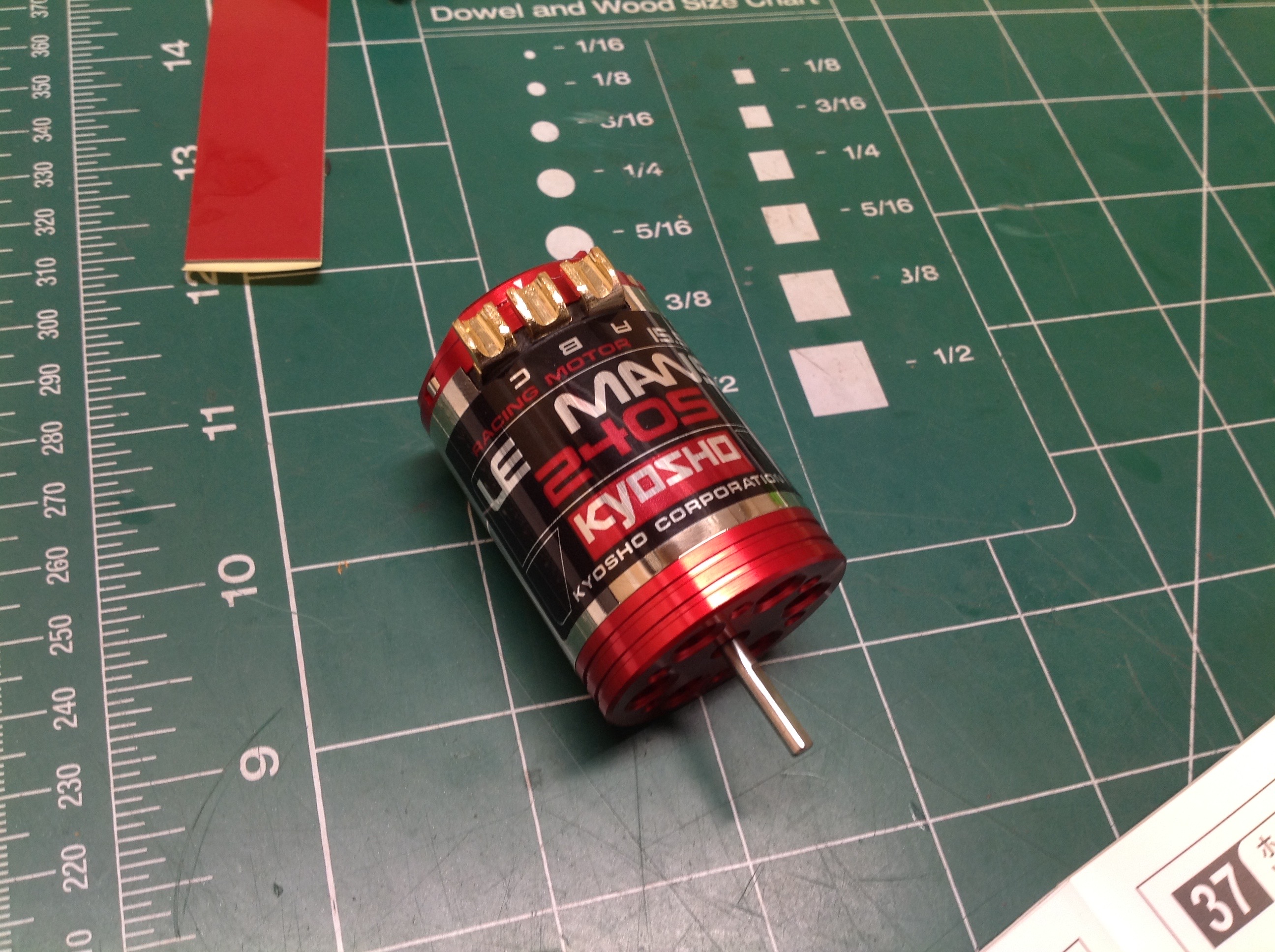
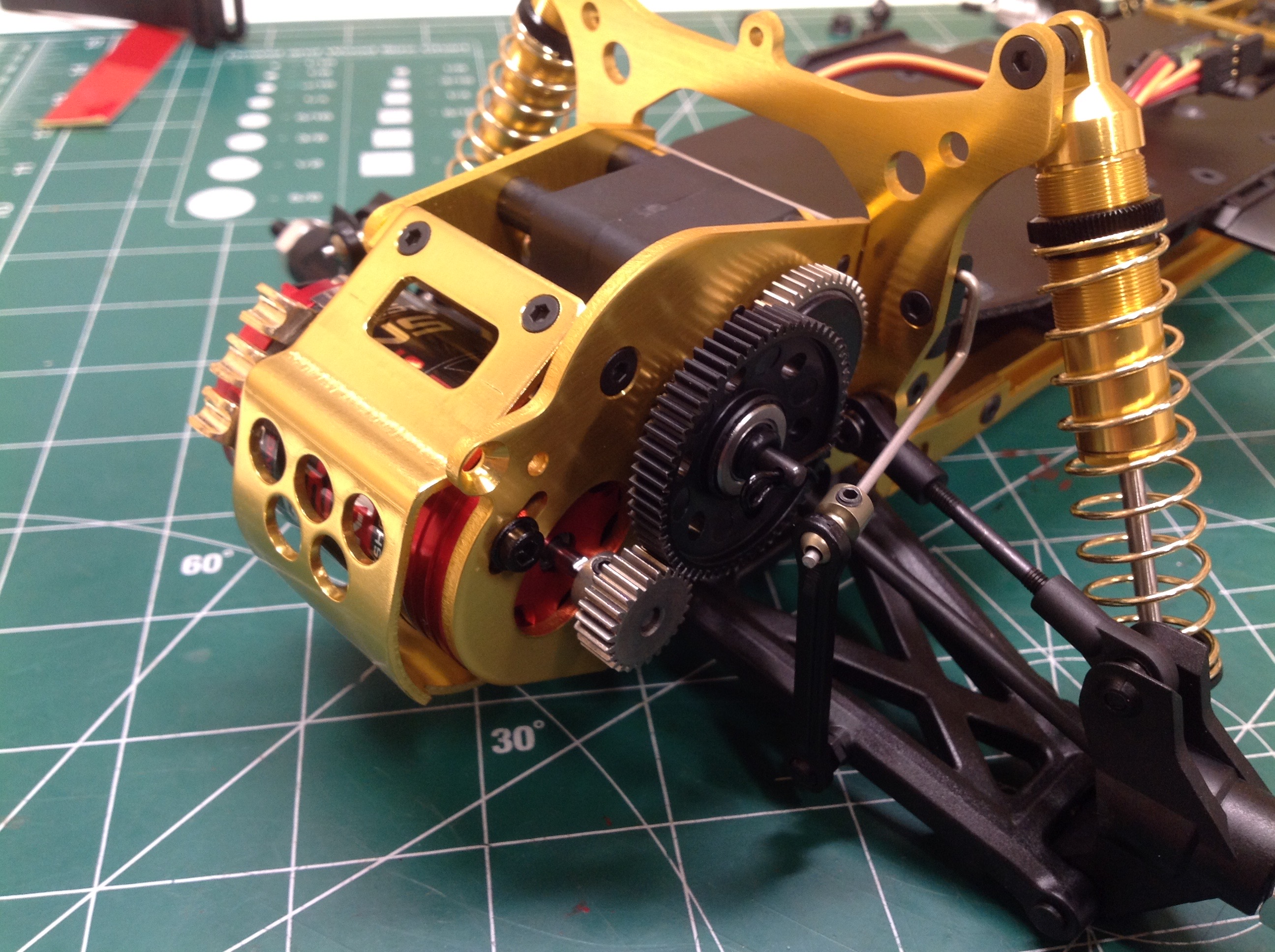
Regardless of how this motor might perform, it looks great with the
shiny petal can and chrome label. This is a 15.5T motor which is
the hottest recommended for this model. On the right you can see
the motor installed along with the stock 25 tooth, 48 pitch
pinion. The model will accept a wide range of pinions from 16T -
31T. The spur is the only plastic gear in the model. Note
that I'm not that bad at adjusting gear mesh, I just haven't done it
yet.
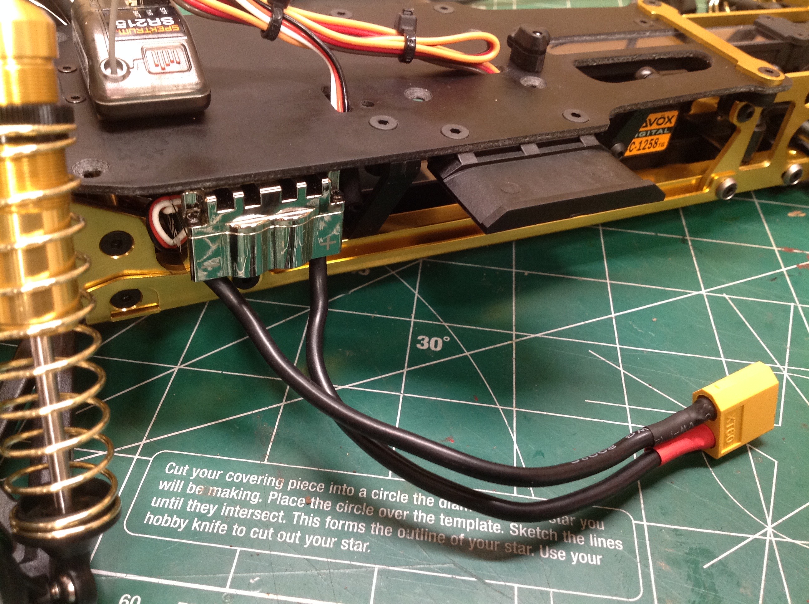
Look at this tiny, chrome silver controller! I really like how
small it is, and the size is convenient because there isn't much room on
this chassis for electronics. I'm not sure how they did it back
in the day with a mechanical speed controller. I used to servo
tape to stick it to the bottom of the chassis plate and soldered on my
standard XT60 connector.
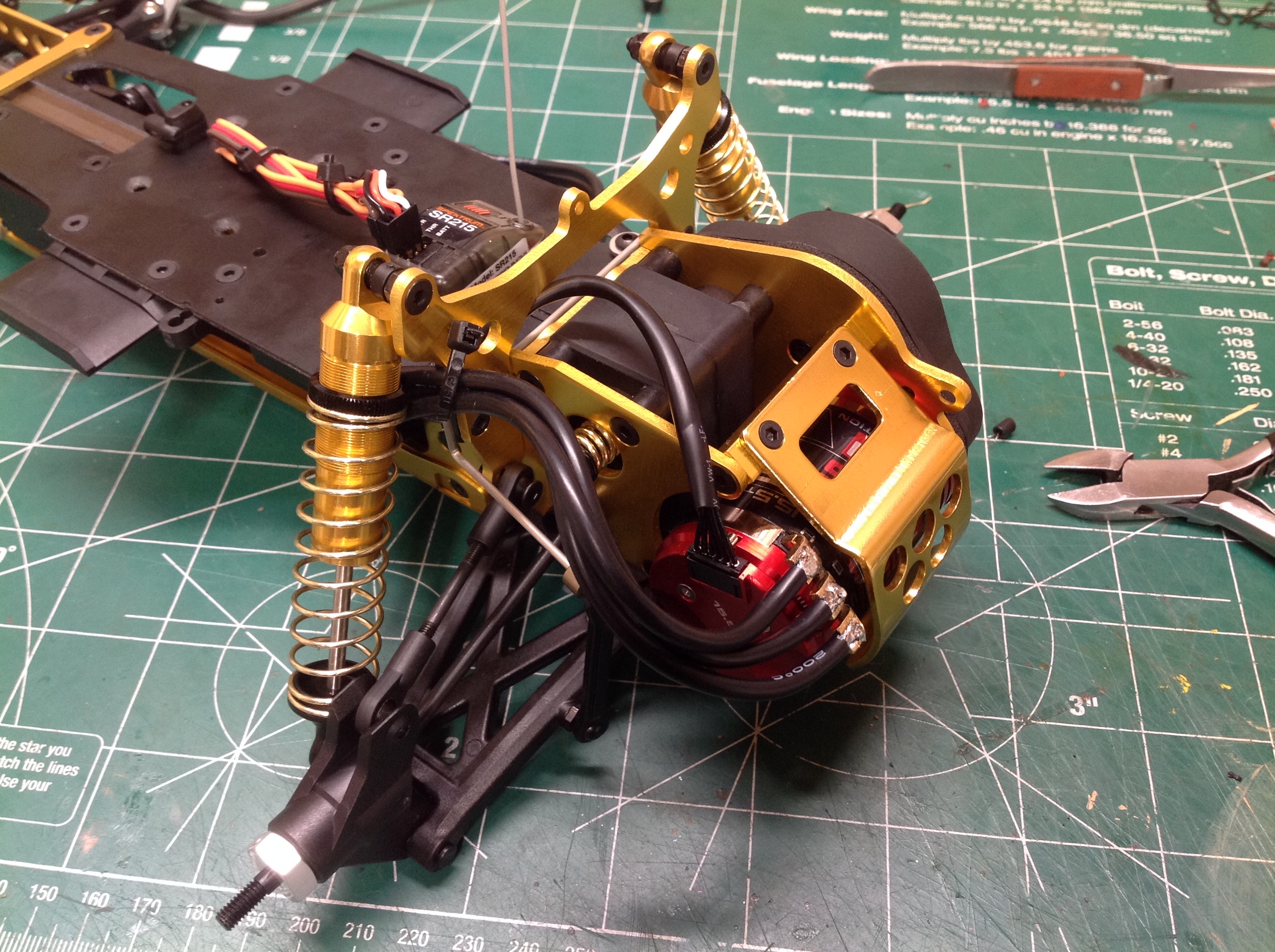
I had to cut each wire carefully to size and solder so that they
wouldn't interfere with anything. This chassis is really designed
for a brushed motor with wires coming out the end rather than a
brushless motor which has them coming out the side, so there isn't much
room available. I ran the sensor wire under the shock tower.
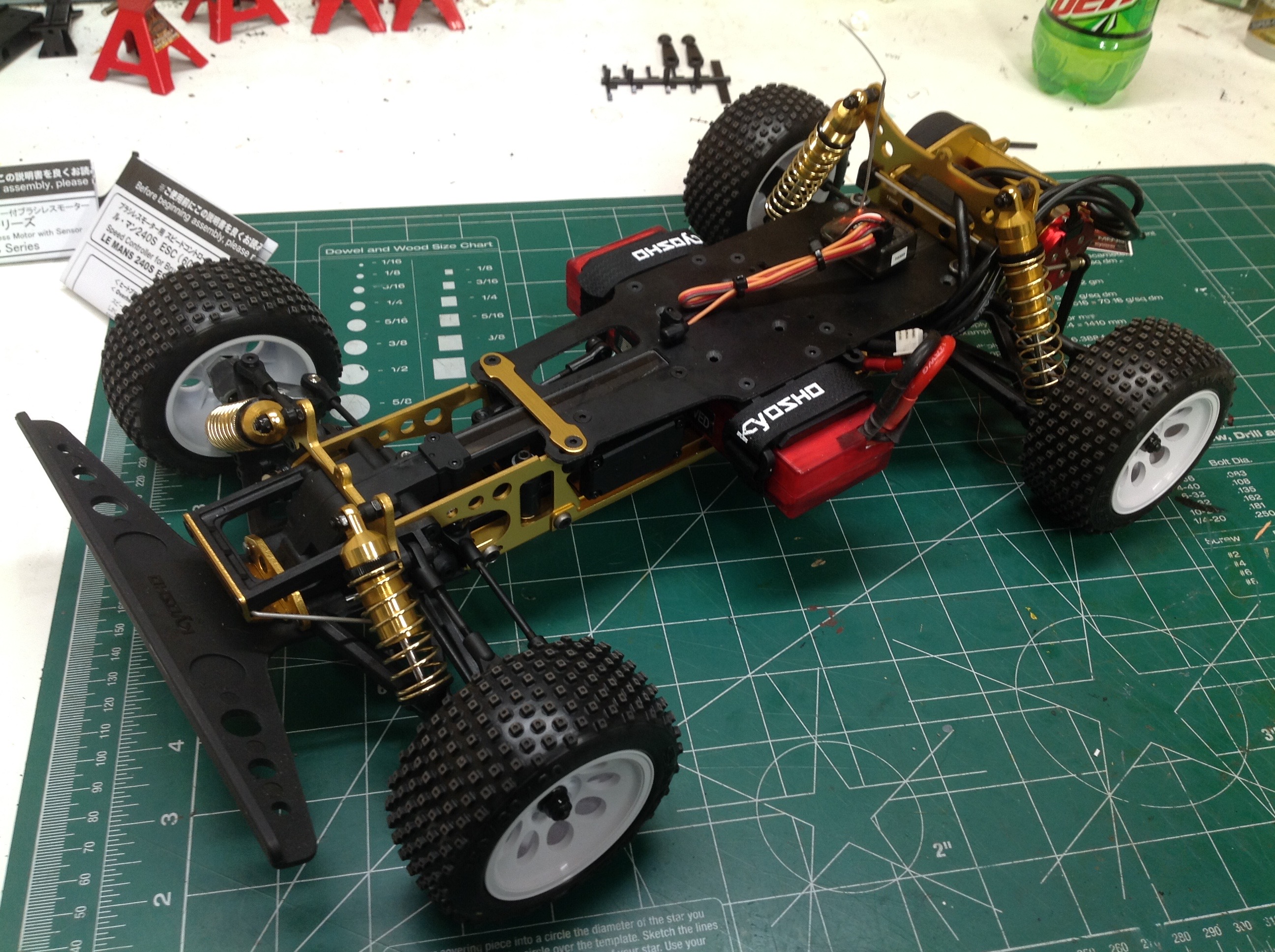
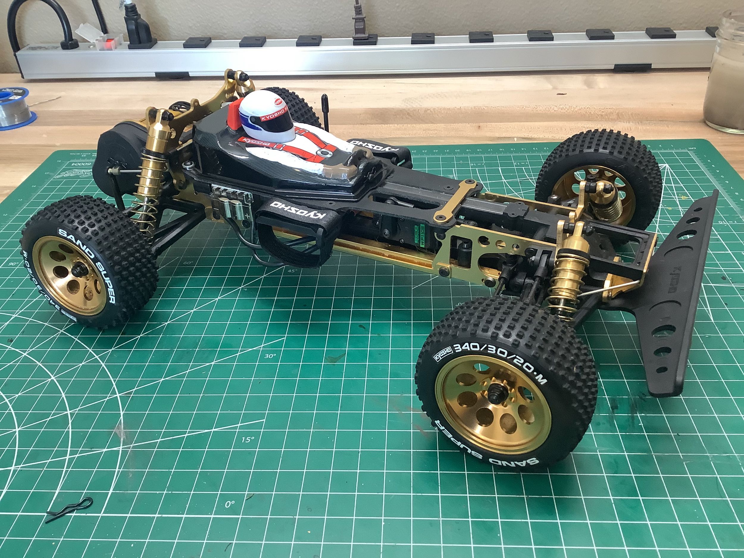
The final picture shows the rolling chassis with wheels, tires, and a
hard battery pack installed. At this point it can be driven.
Update:
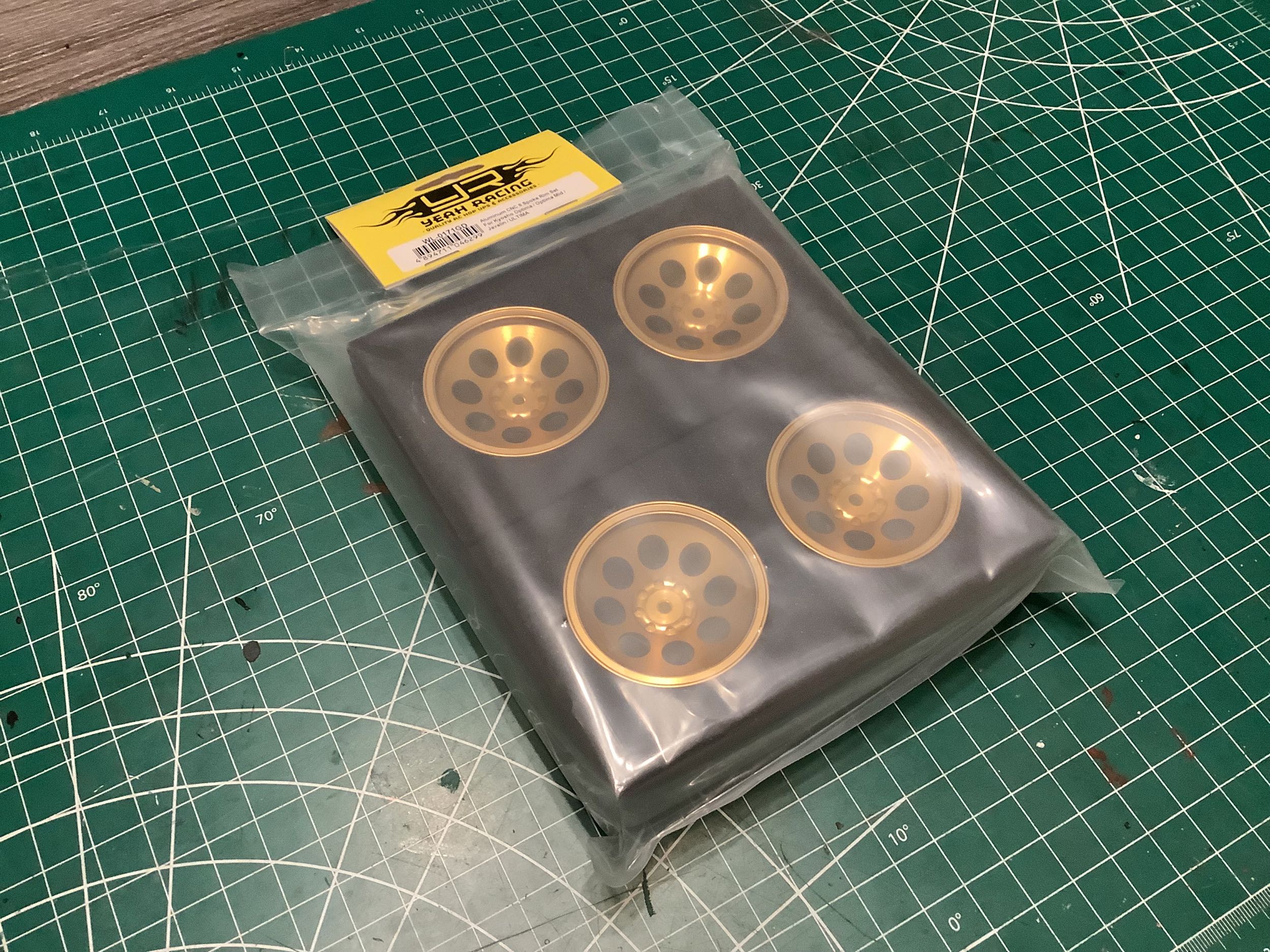
For my replacement Turbo Optima after the fire, I got some gold aluminum wheels and applied the white
lettering on the tires via sticker (which I hadn't noticed existed the
first time). I don't think the stickers will stand up to actual
driving though, so I got an extra set of tires and I will use the
original white wheels with those tires when running the model.
©2019/2023 Eric Albrecht