Axial RR10 Bomber Project
Page 1: Stock Assembly
I took very few pictures of the assembly process for some
reason. I'll try to discuss the important points even if there are
no pictures to illustrate them.

The very first things which are built are the axles. There are
no differentials in this model, so the metal ring gear is just attached
to a locked spool. The axle housing is one piece plastic and
support the ring and pinion gears with their bearings. The diff
cover is removable after the axle is installed on the vehicle in case
the diff needs to be accessed, which came in handy for me when I broke
the spool. The pumpkin is not centered on the axle housing so this
means the axles are different lengths. Front and rear use the
same axle housing and spool, but have different end. The kingpin
axis of the steering knuckle is inclined with a determinant
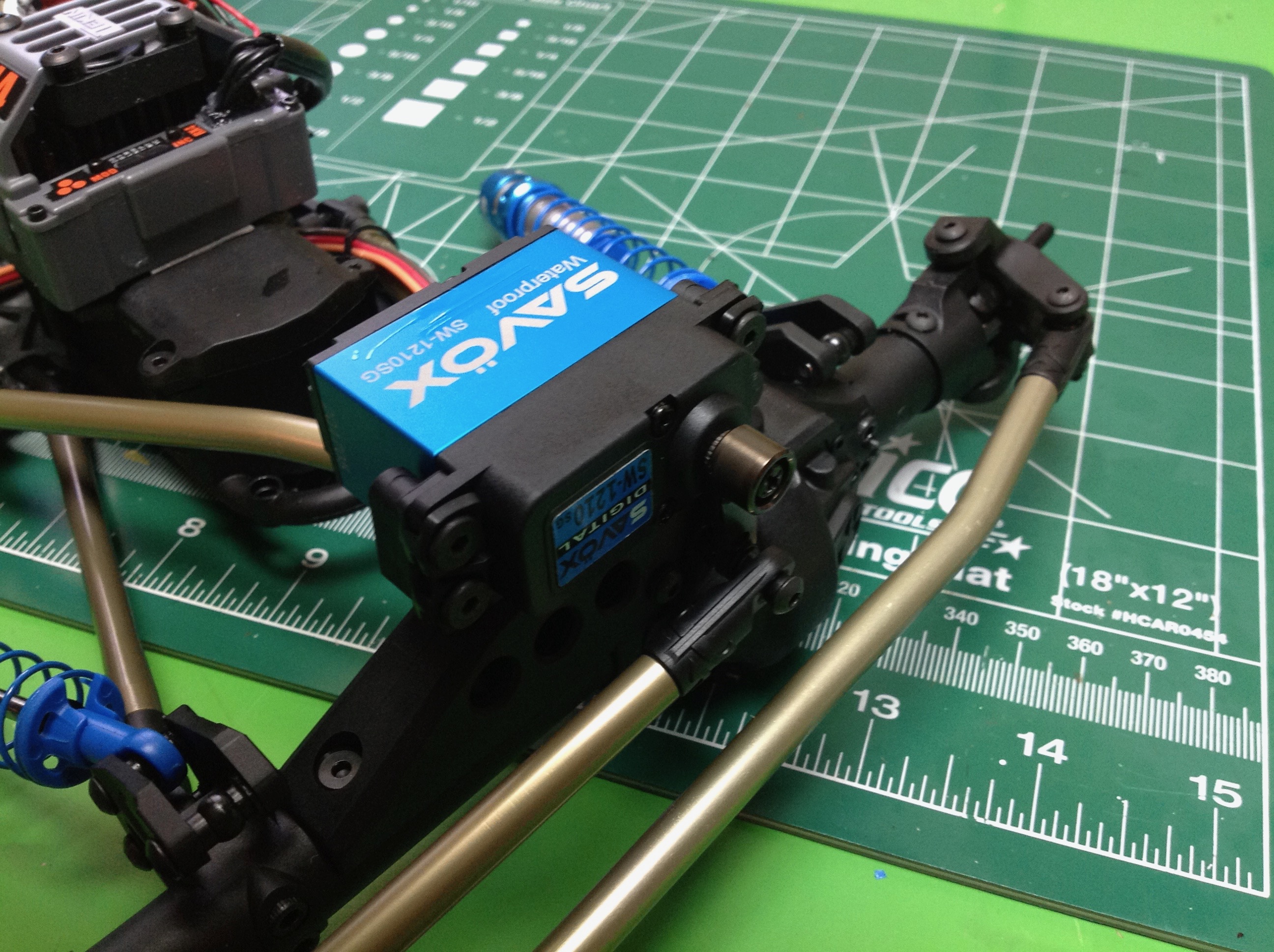
assembly. Next all the links, both suspension and steering, are
assembled. The rods are aluminum and the rod ends and balls are
plastic. Finally the steering servo is mounted directly to the
front axle as shown. I used a waterproof servo and an aluminum
servo horn. The kit supplied plastic horn bent like crazy under
the high torque of this servo. The lower links for the rear
suspension are not just rods, they are much stronger rectangular
sections with aluminum side stiffeners.
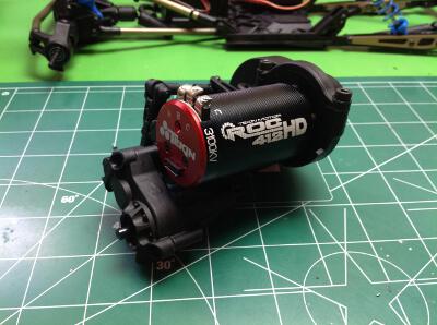
The next think to construct is the transmission. I never built the
transmission in stock form, but installed the optional 2-speed shifting
transmission instead. The gearbox uses all metal gears except the
spur gear which incorporates a dual pad slipper clutch. I chose a
Tekin ROC 412 HD sensored brushless motor. There is plenty of
room for the long 550 sized can. I could not use the stock pinion
because this motor has a 5mm shaft instead of a 1/8" shaft so I bought a
new steel pinion.


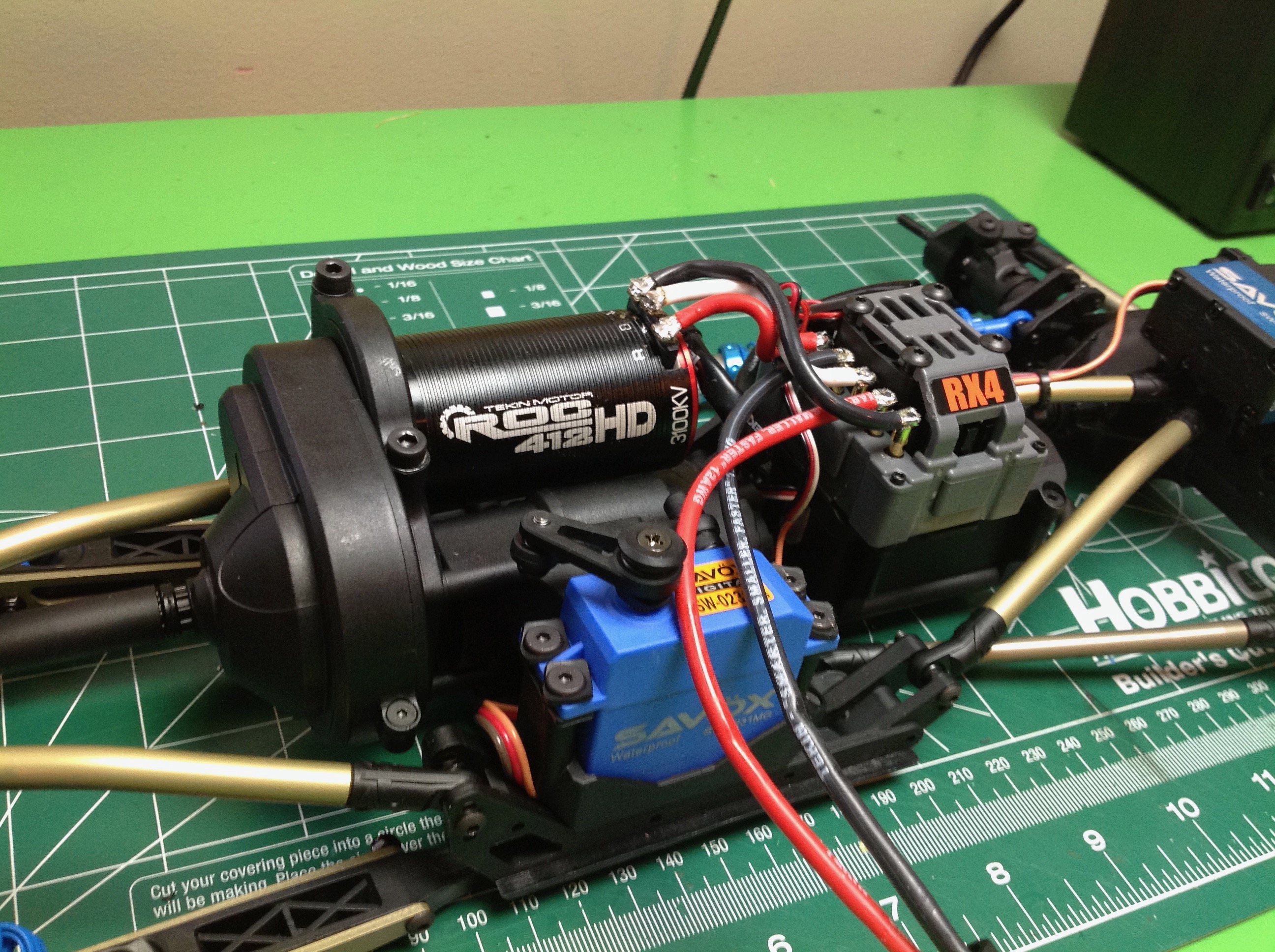
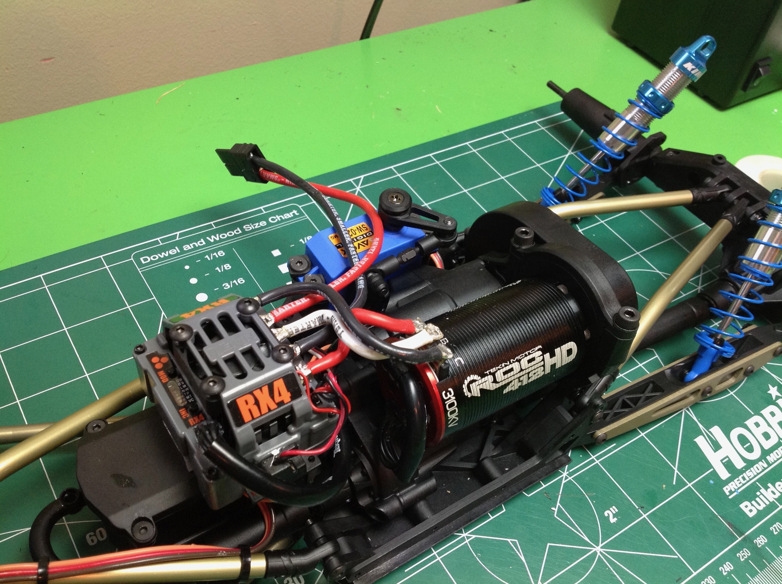
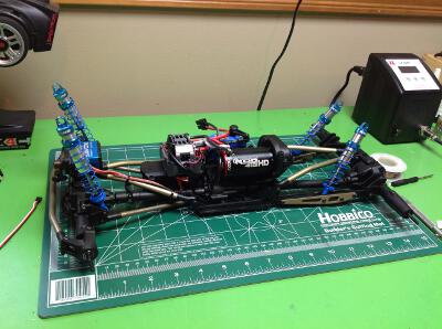
Next the gearbox is installed onto a slide plate and then the axles and
links are connected. The radio box is directly in front of the
gearbox. The Tekin RX4 speed controller is very large so it was
tricky to find a spot for it that wouldn't block the body later. I
ended up sticking it to the top of the radio box. You can see the
very short wires soldered between the motor and ESC. The solder
joints need to be very strong because you don't want to have to remove
the body to access this later. I had to do so several times.
The drive shafts are telescoping units with CVD ends. The splined
center portion is plastic and the CVDs are steel. The front drive
shaft has broken several times and should really be replaced with
steel, but this may just force the failures into something more
expensive and difficult to replace. The instructions for the
2-speed transmission are for the Yeti, and although the unit also works
on the Bomber the instructions for installing the servo were all
wrong. I had to figure it out myself. Clearance for the
servo horn and link is not good. The required servo travel is very
small, so you need a radio with adjustable end points. I ended up
only using about 20% of available travel. I couldn't use a
shorter horn or it would not clear the side of the servo.
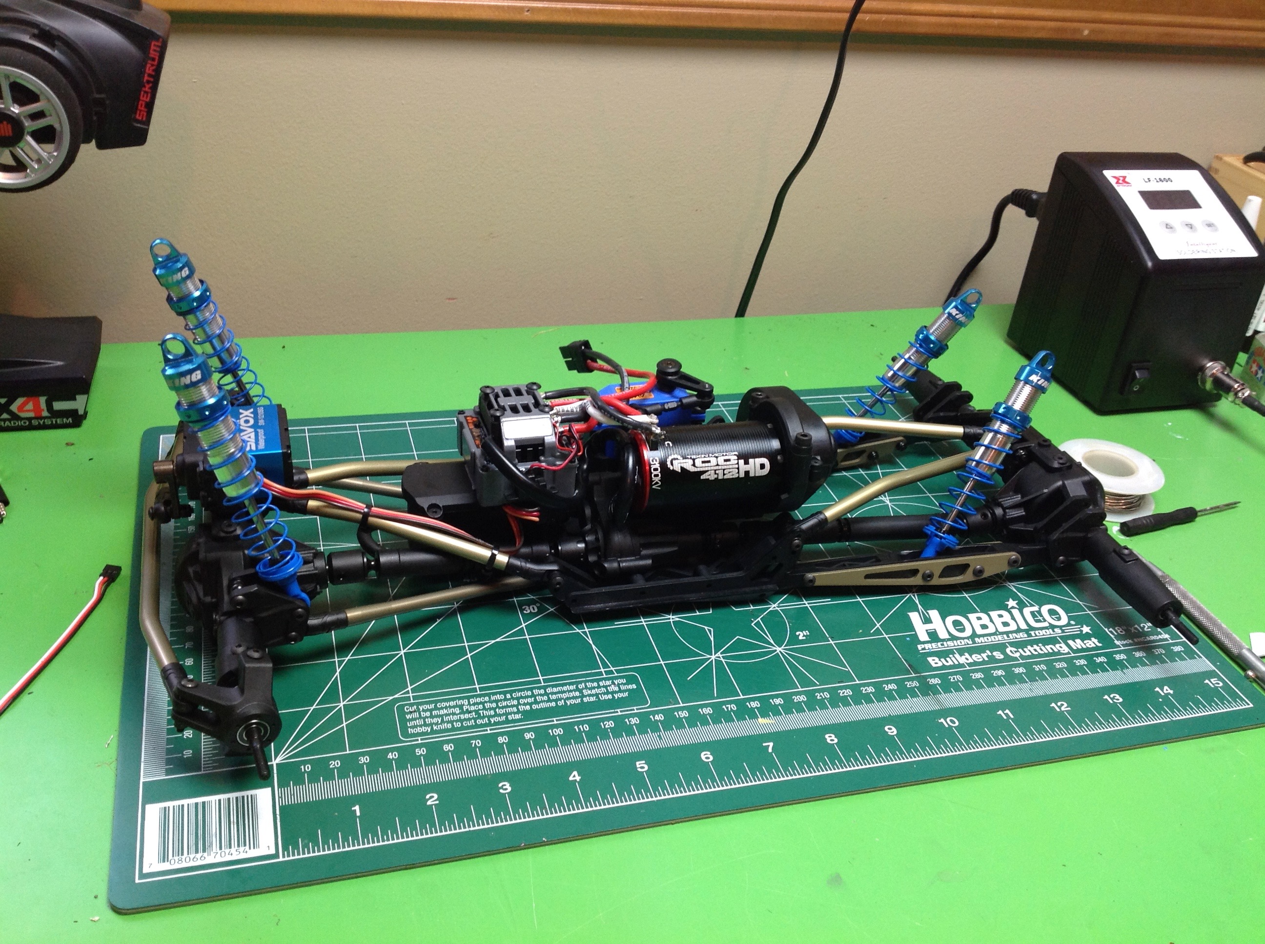
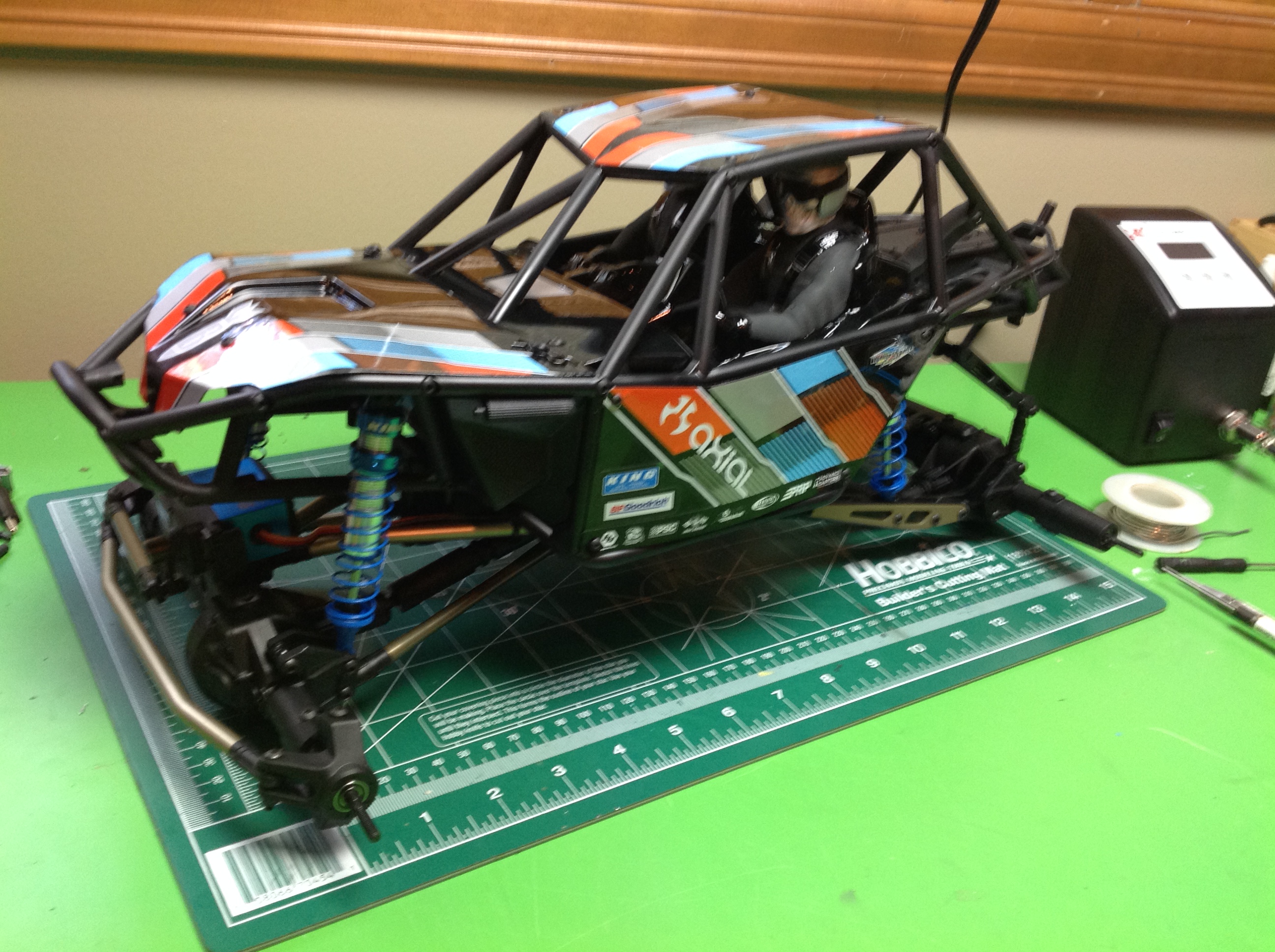
The shocks are the last part of the chassis to be built. these are
oil filled, aluminum units with a pretty long stroke. This is a
good time to point out that this is a not a traditional ladder frame
chassis. There are no side rails here. At this point in the
assembly the whole thing is a floppy mess held together only with
links. The cage has to built and used to support the whole thing.
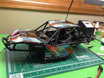
The frame cage is built of perhaps a dozen plastic sections and maybe a
hundred screws. It takes some time to get it all together.
The body panels are just flat sheets of Lexan which are painted.
Most of the decoration comes from the stickers. There are two full
sets of stickers for two different general looks. The is also a
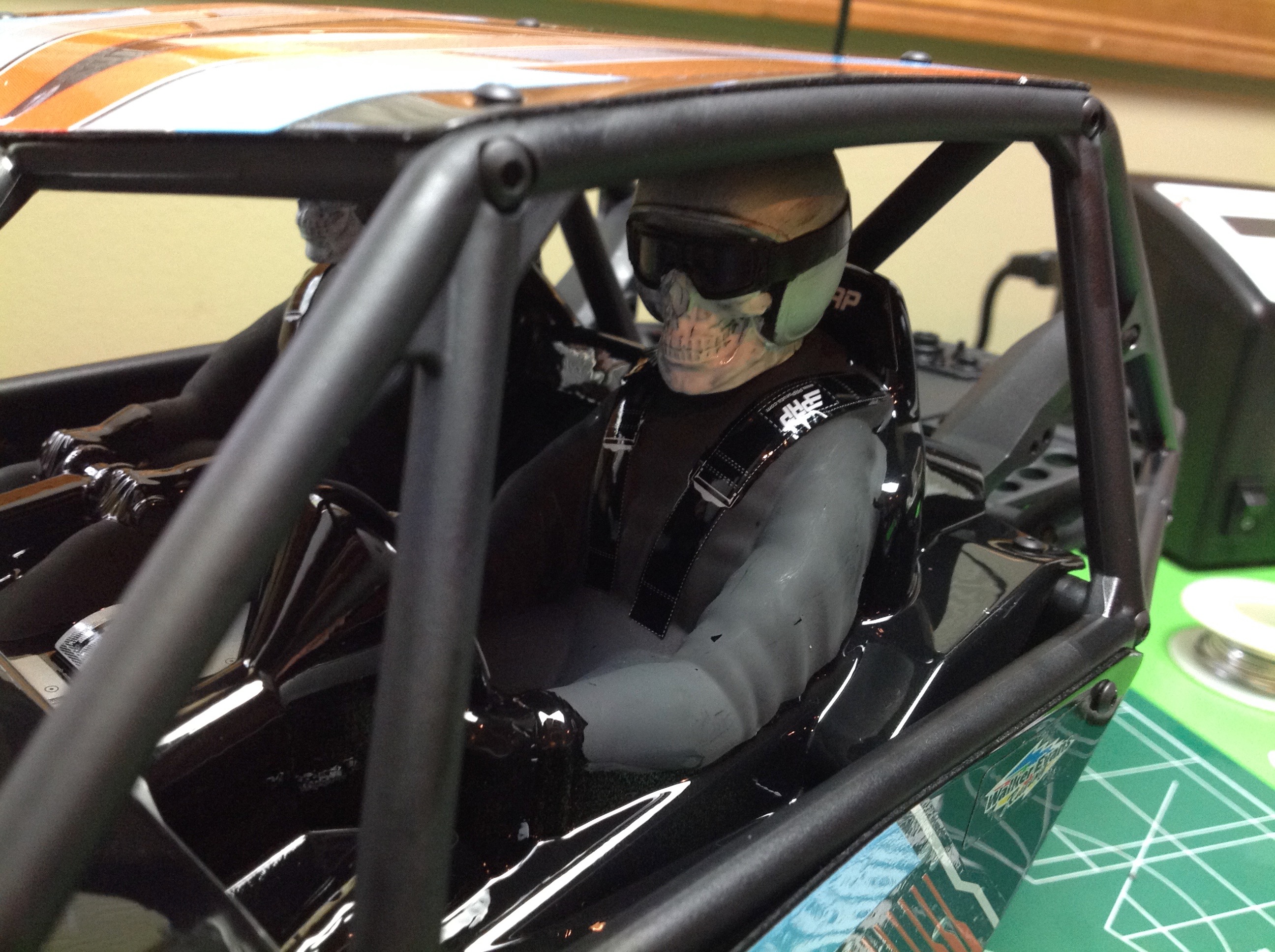
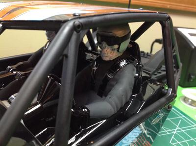
Lexan interior. The driver and co-driver have optional
heads. You can use either traditional helmets or skeletons.
Naturally I chose the skeletons.

Only after the body is installed does the whole thing finally become
stable. It is a total rigid rock with everything connected.
There are 10 screws connecting the body to the base: one for each shock,
four at the base of the doors, and two below the radio box. The
kit also comes with the rear sway bar option which requires another 2
screws.
©2017 Eric Albrecht