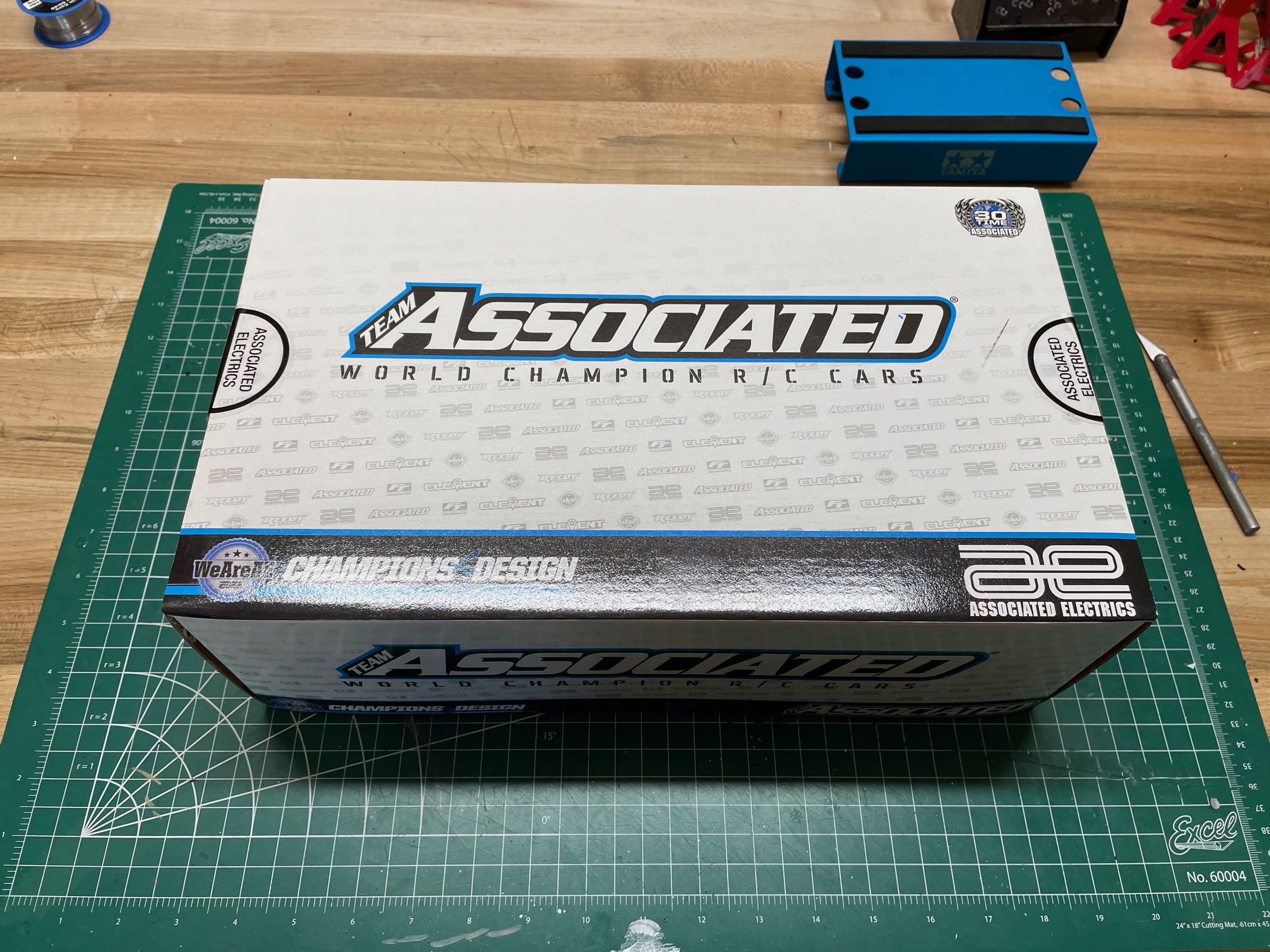
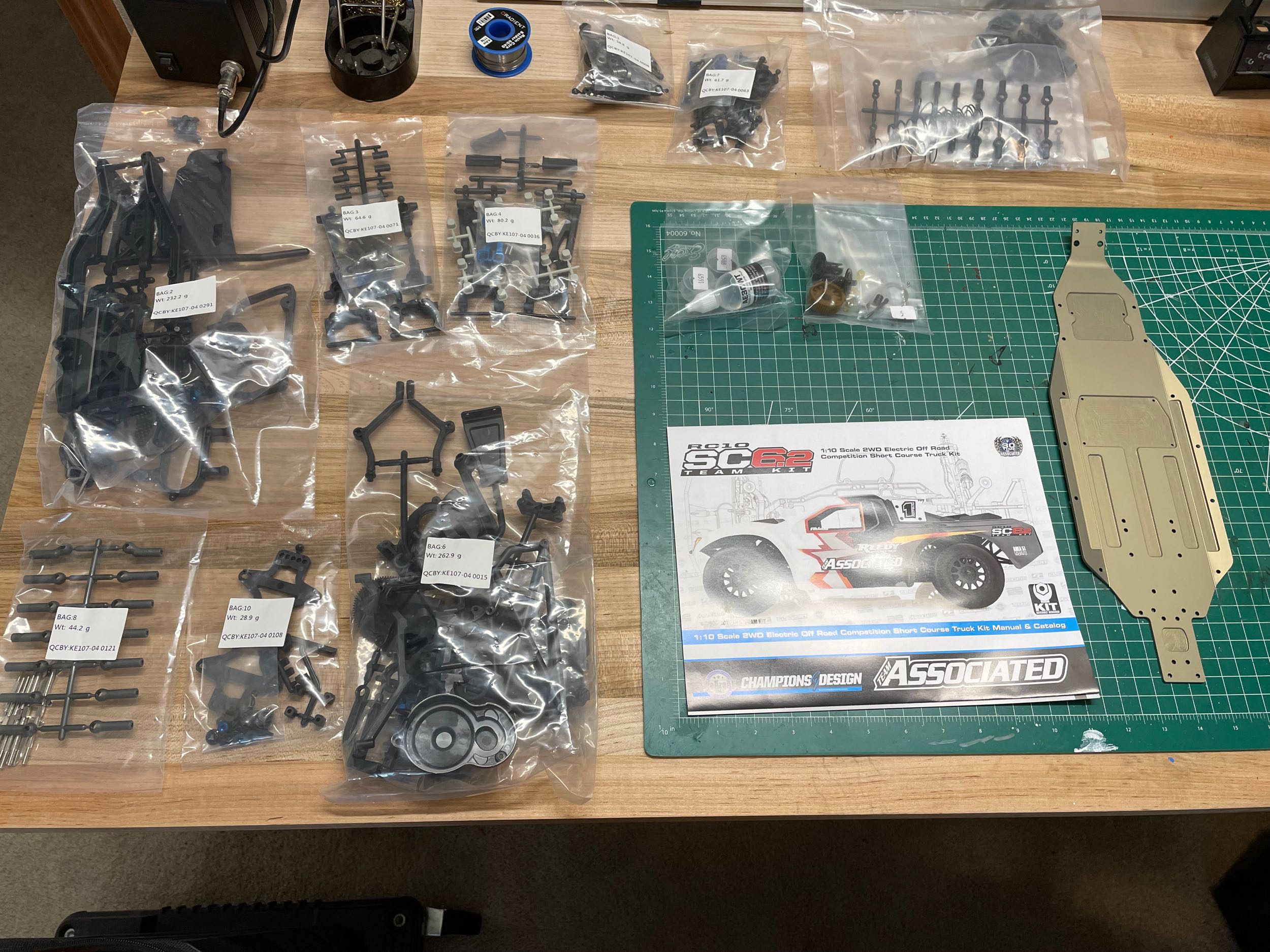
With no body, wheels, or tires included, this kit's
box doesn't take up much space for such a large model. The modest
contents are shown on the right. There is plenty of plastic here,
but the chassis is a formed, anodized, and milled 2.5mm thick aluminum plate.
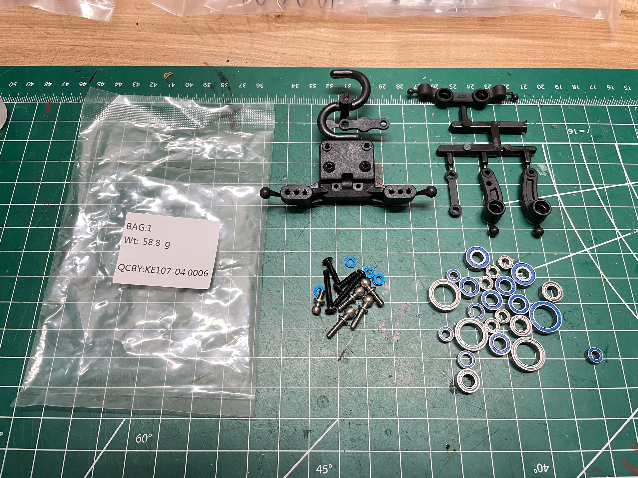
The built starts, not surprisingly, with Bag 1.
The contents of that bag as shown above and consist mostly of the parts
for the steering, but also the ball bearings for the entire kit.
Note that some bearing are rubber shielded and some are metal
shielded. From what I can tell, the metal shielded bearings are
used in sealed areas for minimum friction, but the rubber shielded
bearings are used on external areas to keep them clean.

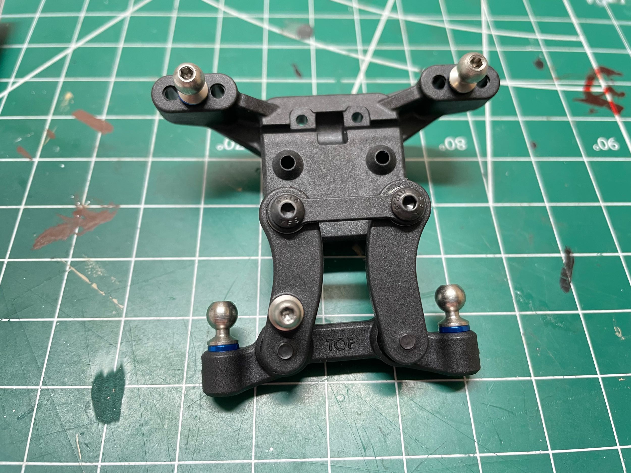
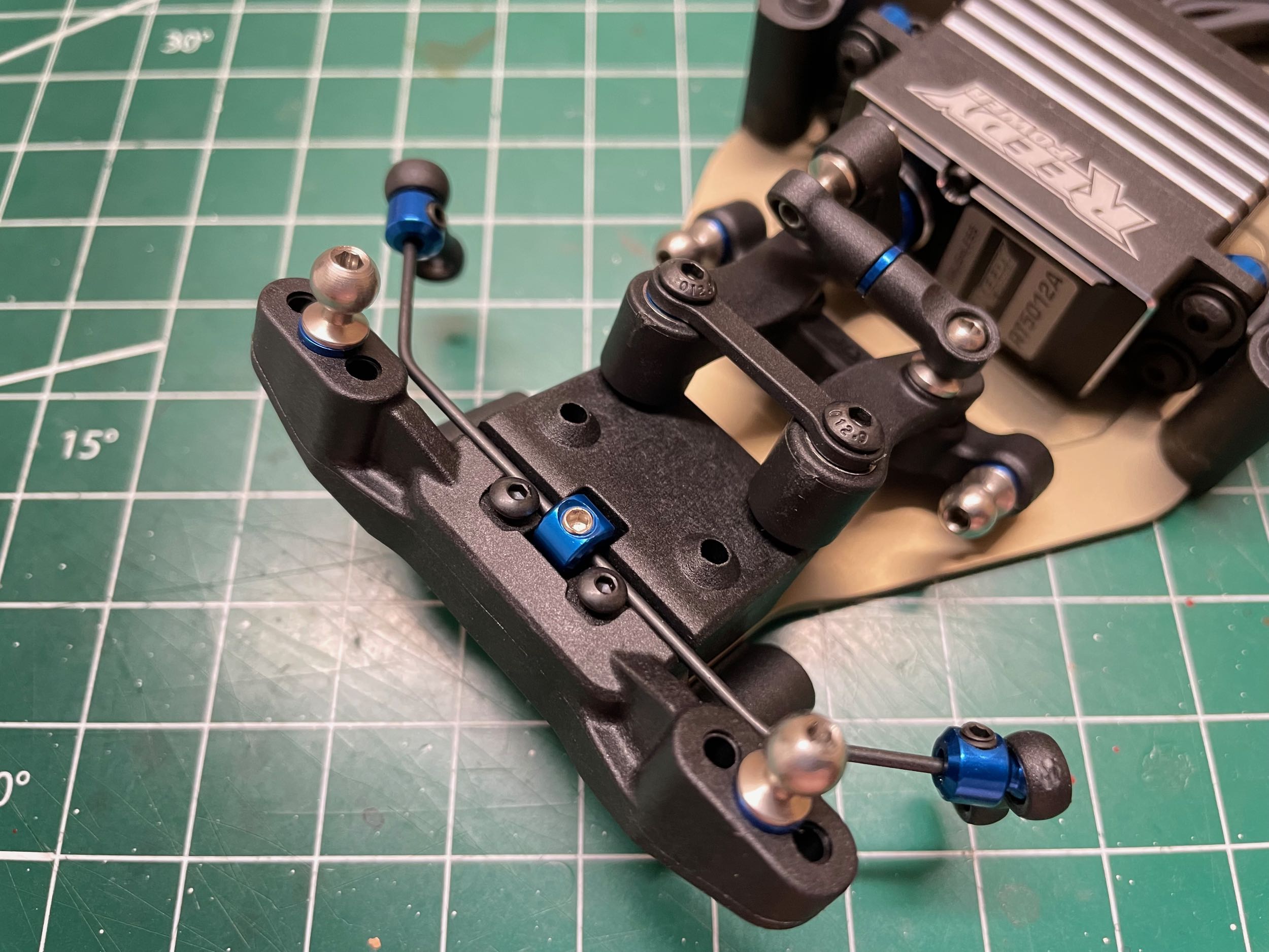
The dual bellcrank steering uses six bearings for
smooth motion. Optional aluminum cranks are available.
Changing the 1mm spacers behind the ball studs will adjust the Ackerman
correction. The cranks are attached to the front upper
suspension bracket as shown on the right. The ball studs are all
installed with
1mm aluminum spacers for vertical adjustability. There are also
multiple holes in the suspension bracket for lateral
adjustability. Different positions would result in different upper
suspension link rotation points which would alter camber response.
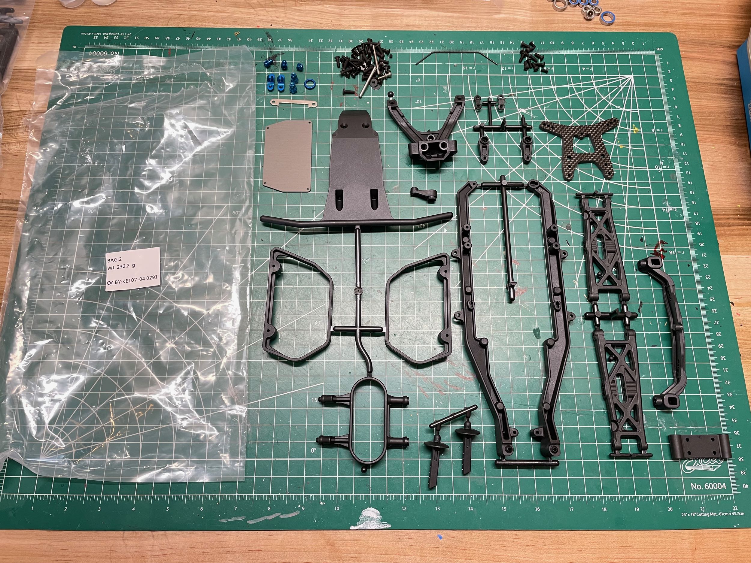
While the first set of parts was very small, the parts
contained in Bag 2 are extensive as shown on the left. Parts are
included for the front suspension, bumper, and chassis bracing. I
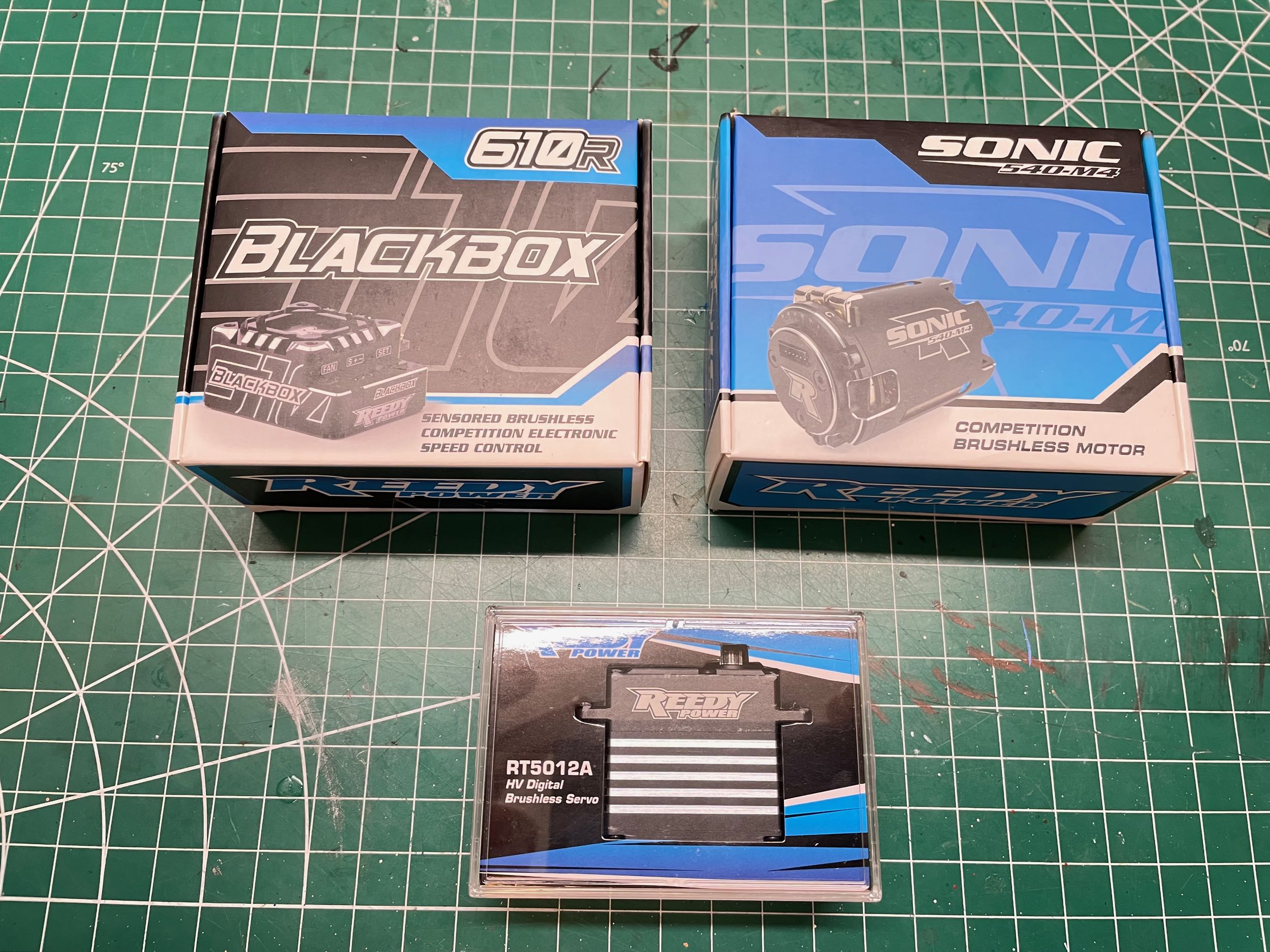
acquired a set of all Reedy racing electronics to go with this set
including a 6.5T sensored brushless motor, programmable controller, and
aluminum bodied high torque servo. I could have saved a lot of
money using Hobbywing instead, but I felt compelled to keep it in the
Associated family for this one.
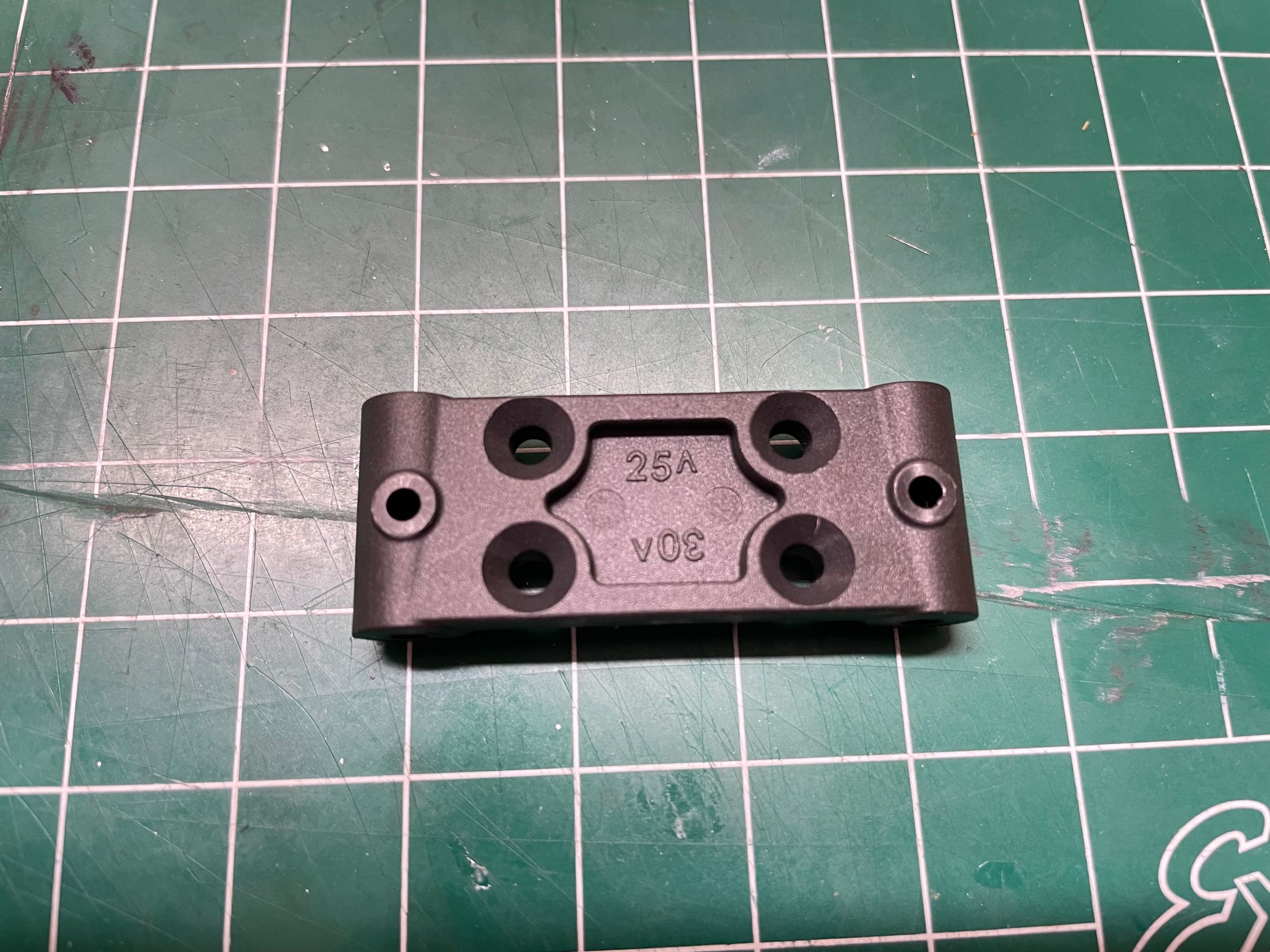
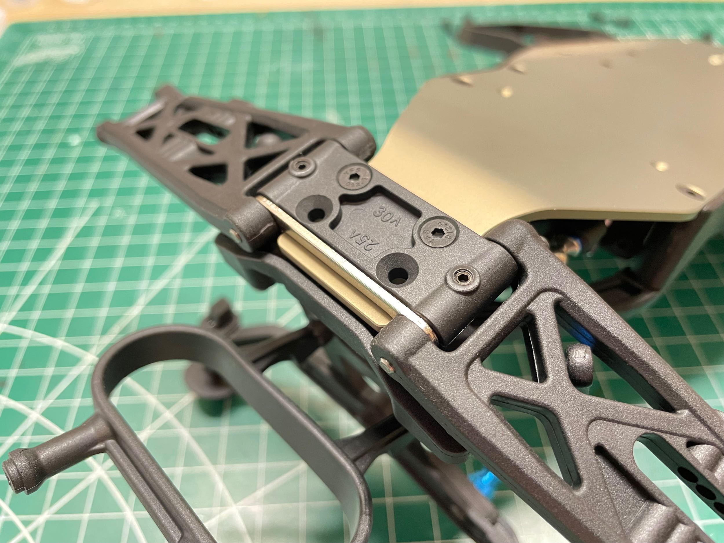
The front bulkhead is shown on the left. You can
see the numbers 25 and 30 molded into it along with arrows pointing to
either end. These refer to the kickup angle which can be modified
by flipping the bulkhead over on installation. The vast majority
of the angle comes from the bend in the chassis plate as shown on the
right. The
chassis bend angle is 27.5° and the holes in the bulkhead are drilled
slightly out of plane offering a modification of ±2.5° to that base
value depending on which way it is installed. The default setting
is 25°. Optional aluminum and steel bulkheads add 10g and 30g of
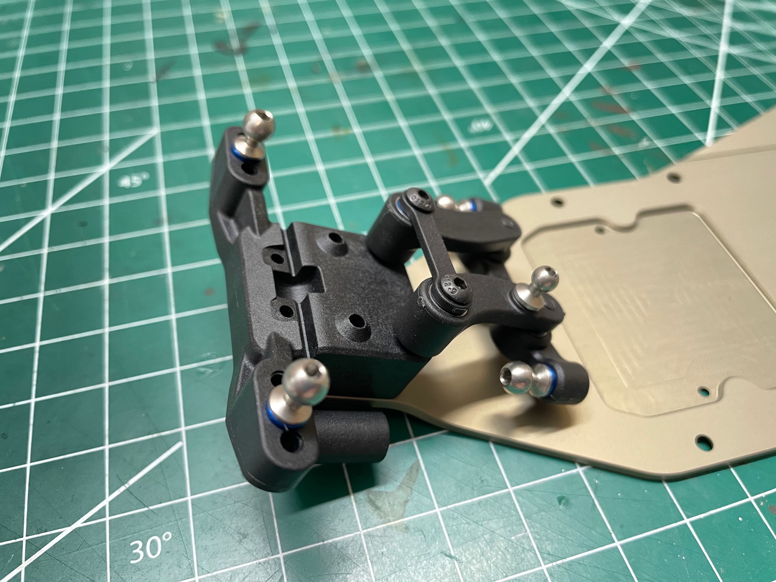
mass, respectively. Note that since the steering cranks are
attached to the
front bracket, they are also angled back with the chassis as shown on
the right.
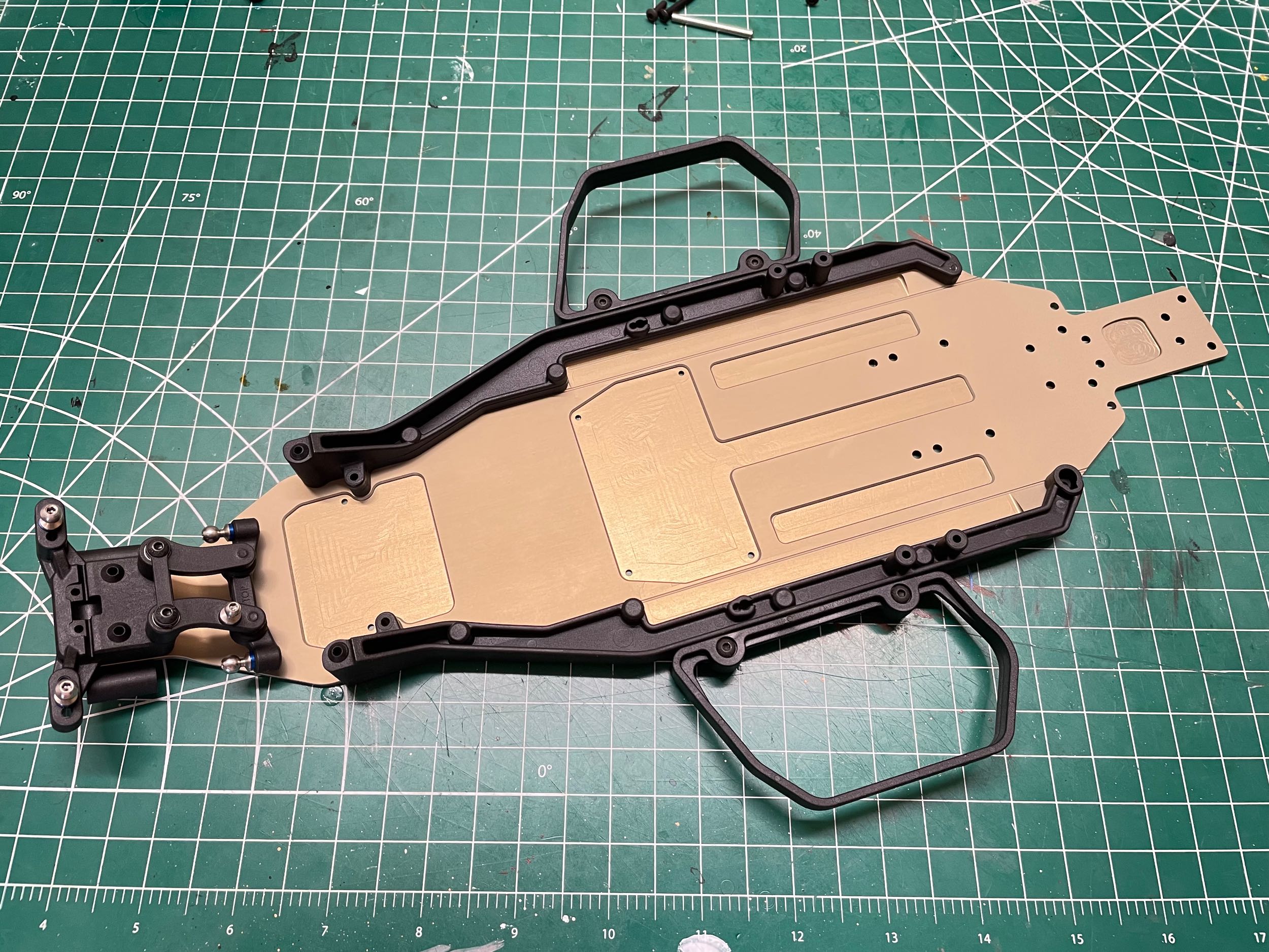
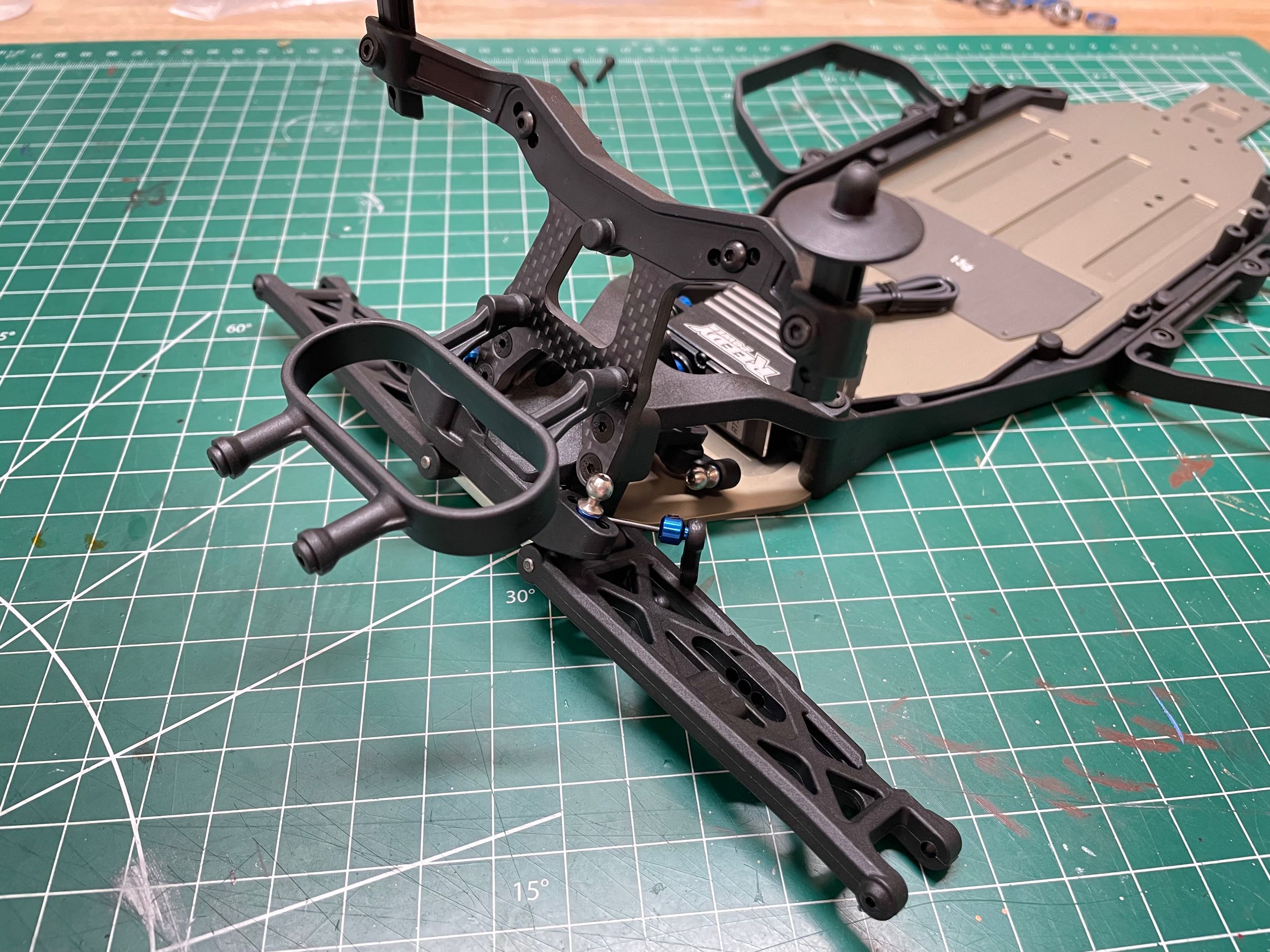
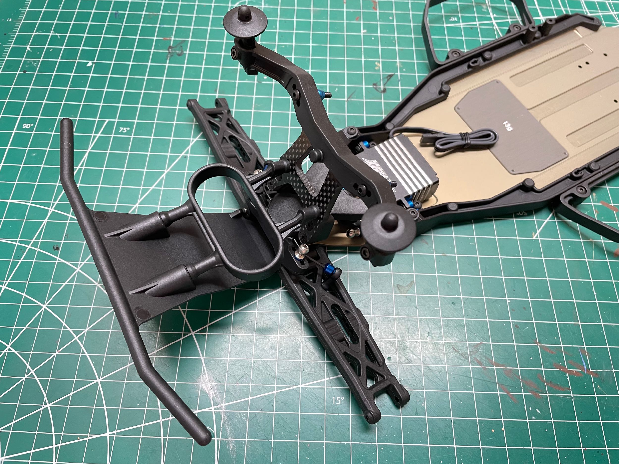
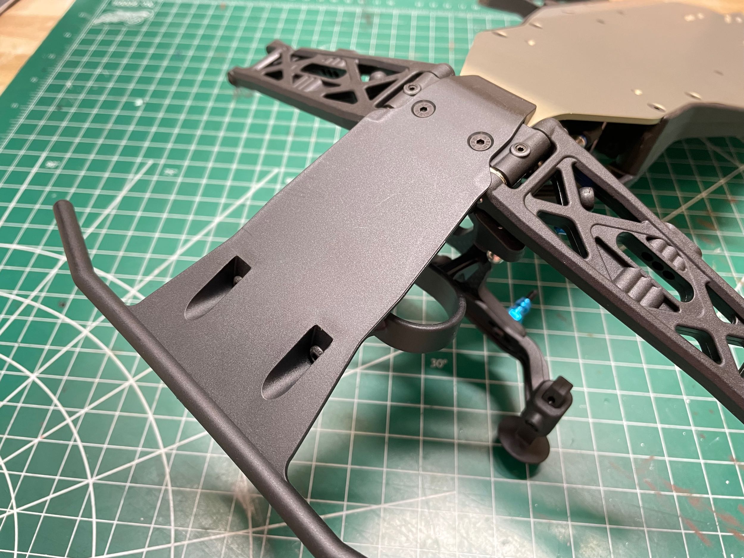
Next these long side rails are attached which stiffen
the chassis and provide a bit of protection for the electronic
components. The nerf bars on the sides are there to provide some
support for the much wider body in the event of a rollover. Note
the machined pockets in the chassis plate. We'll come back to
those later.
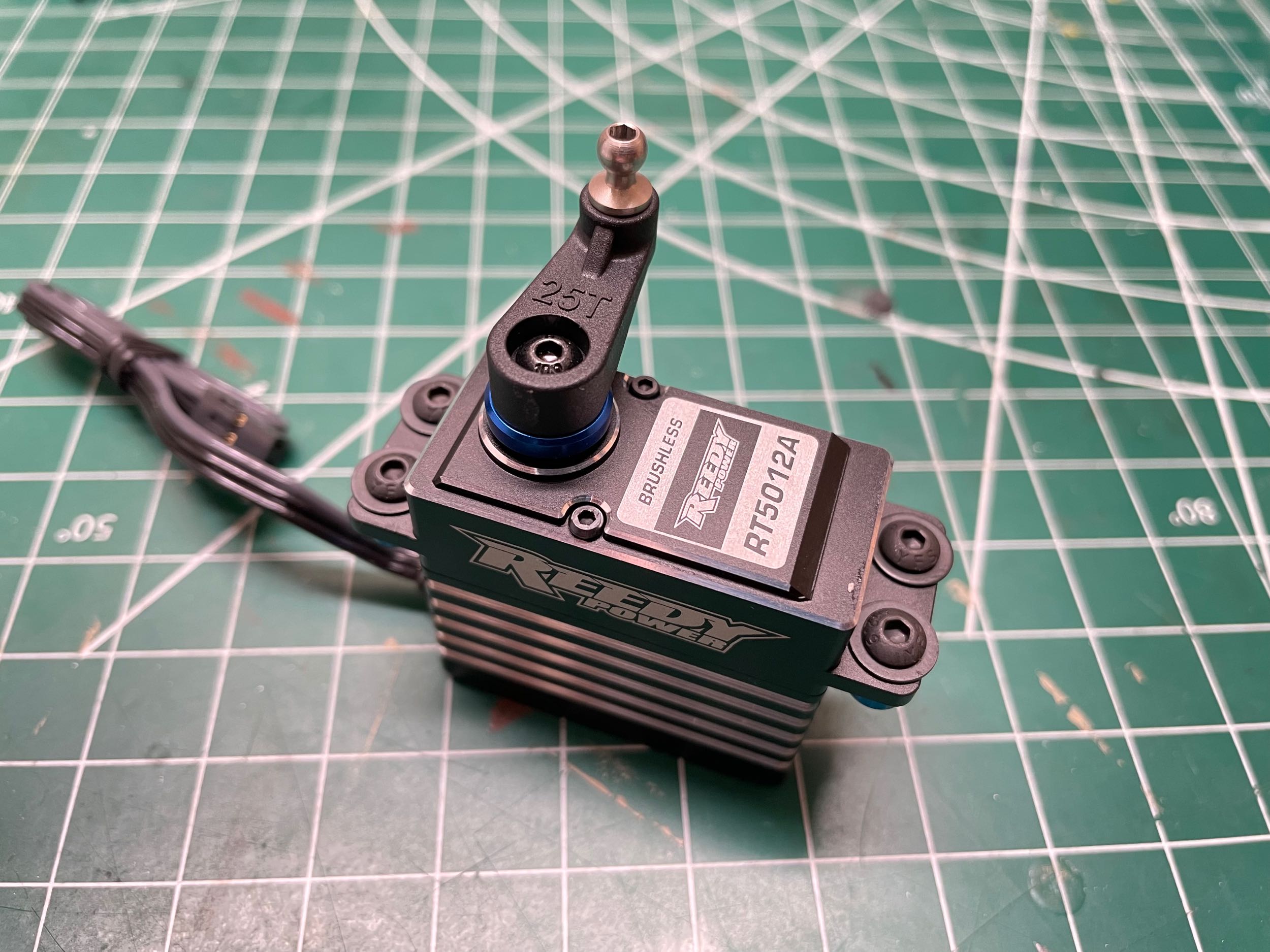
There is no servo saver; the plastic servo horn
attaches directly to the steering servo for maximum control
precision. I suppose the fact that the horn is plastic at least
offers a minimal amount of cushioning compared to metal, although
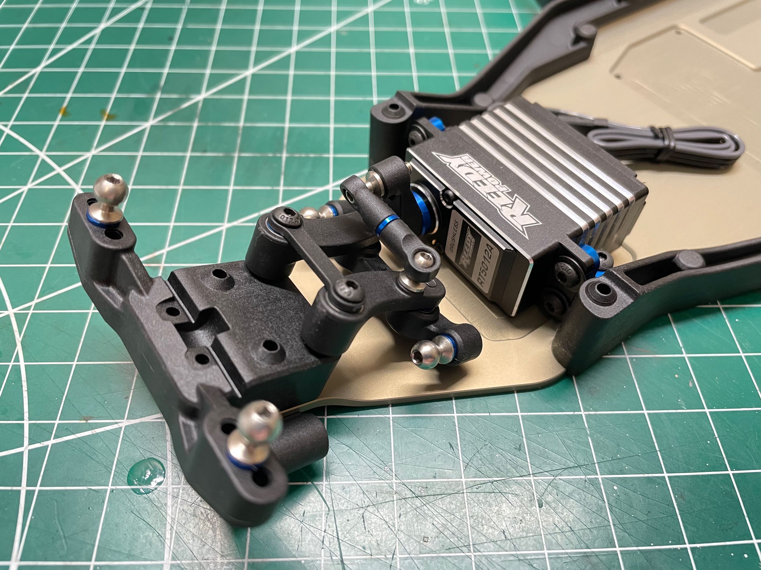
optional aluminum horns are available. The
steering servo is shown installed at right along with the tiny steering
link. The servo mounts to the plastic side rails, not to the
aluminum chassis plate so it actually floats slightly above the chassis.
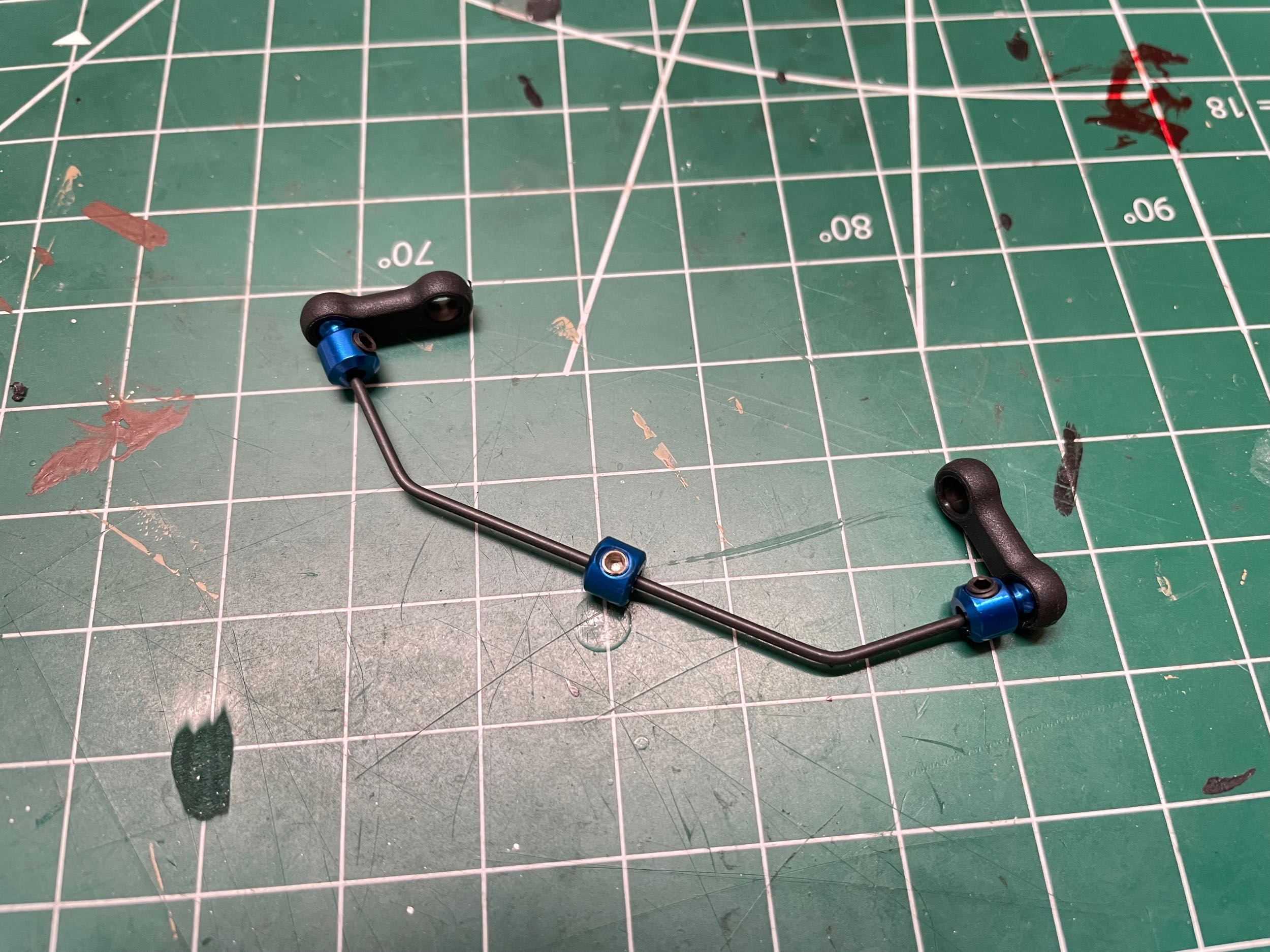
The front sway bar is made from a 1.3mm diameter bent
steel wire. Optional thickness of 1.2mm and 1.4mm are available. A collar in the middle will keep it centered in the
front bracket while ball studs on either end will allow short rods to
connect to the lower suspension arms (later). The sway bar is
shown installed in its slot on the right. It will be captured by a top plate later.
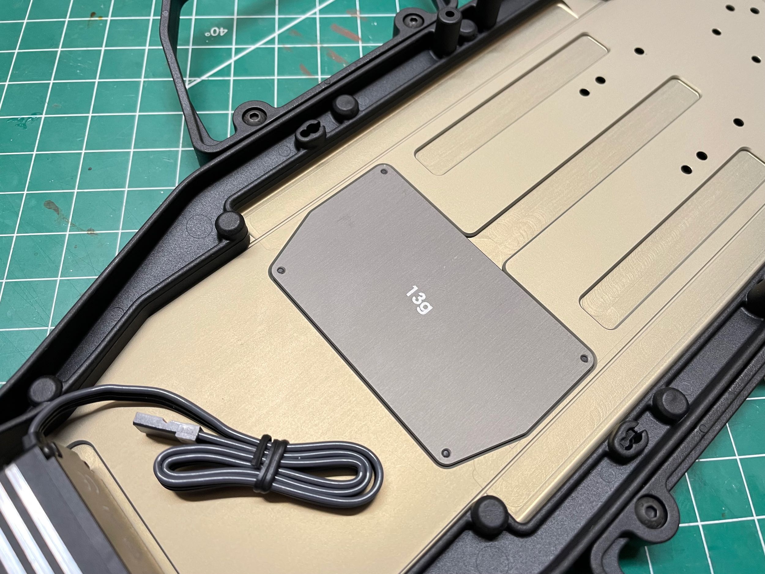
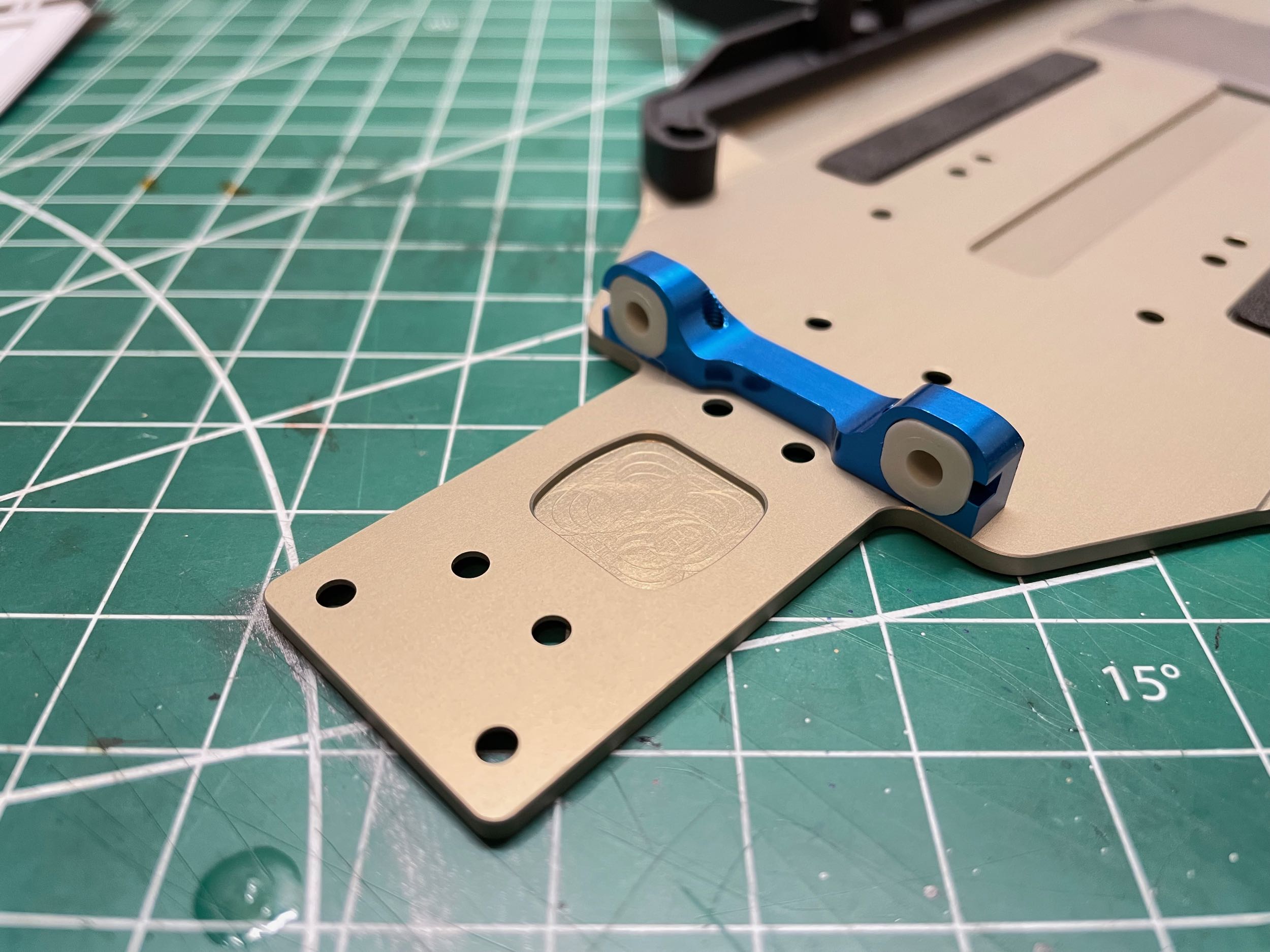
There is a milled pocket in the chassis which
accommodates weighted plates used to adjust the weight and balance of
the vehicle. The aluminum plate included in the kit is labeled as
having a mass of 13 grams. An optional thinner 9g aluminum plate
is also available, as are 24g and 36g steel plates, and an 8g carbon
fiber plate. If the electronics are installed onto this plate,
they can be easily changed as a unit. There is a second pocket
under the servo which is empty by default, but can accommodate a 5g
carbon plate, a 9g aluminum plate, or a 24g steel plate. This is
the
sort of thing I will never be changing. In fact, I won't be
changing any of the adjustments available on the chassis at all.
When you can't drive, nothing matters.
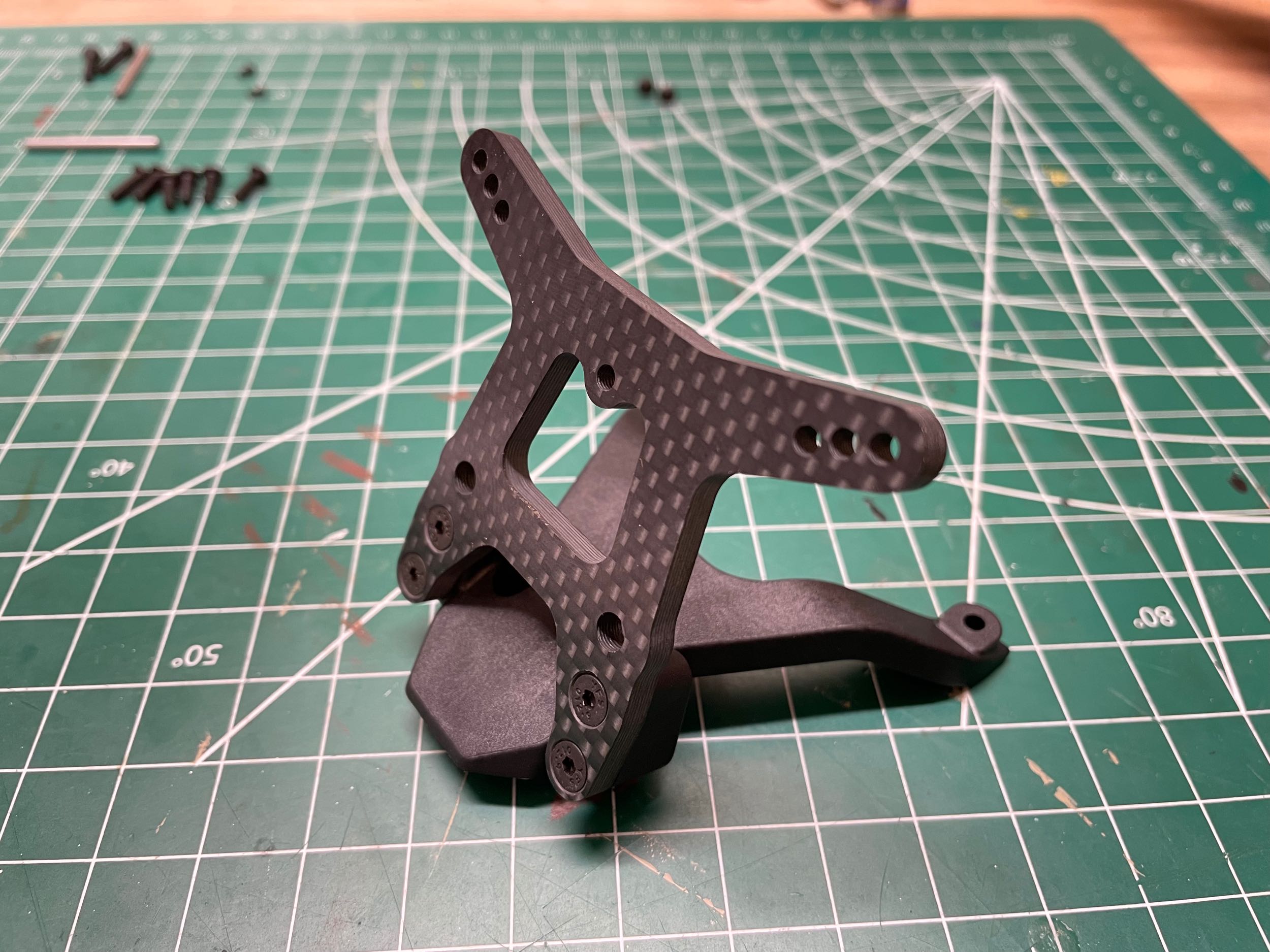
The 4mm thick front shock tower is made from carbon
fiber
plate and is attached to a plastic top plate. It is tilted back at
roughly the same angle as the chassis kickup. There are three
hole options for the upper shock mounting point. The center hole
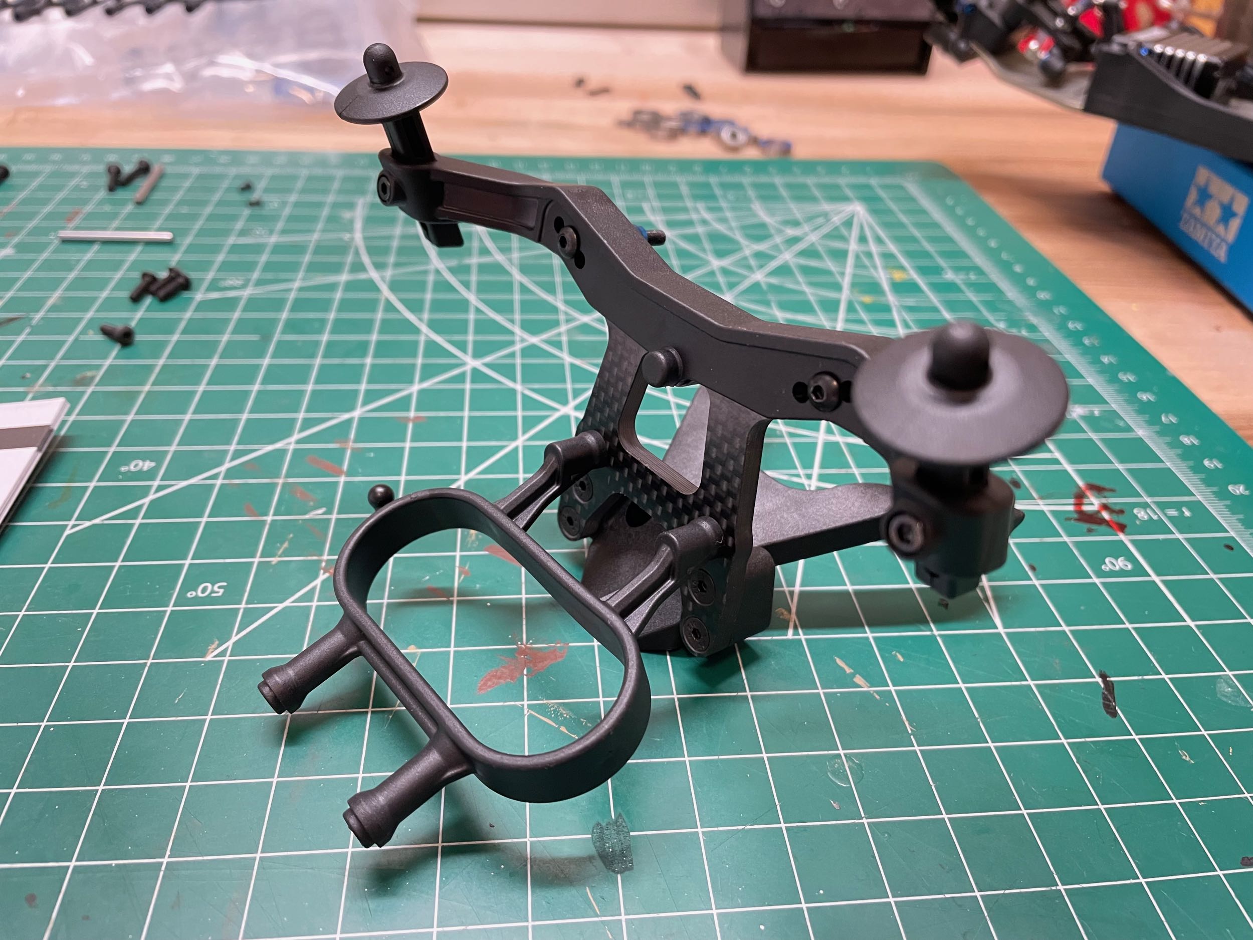
is used by default. The front body
posts are attached to a bracket at the top of the shock tower as
shown. The bumper brace shown on the right is in the shape of a
loop to allow it to deform and absorb a lot of energy without breaking
in the even of a front impact (which happens a lot).
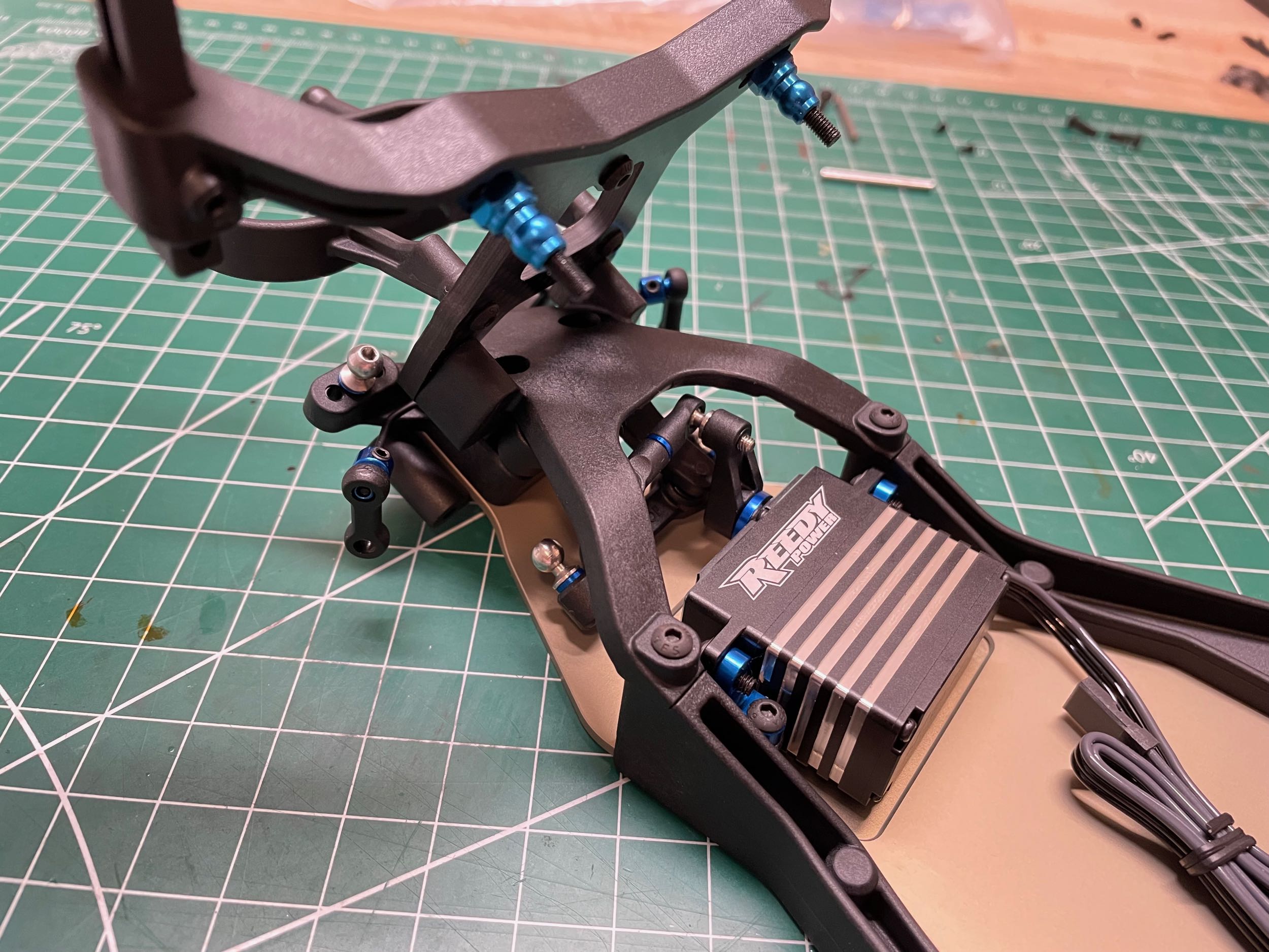
The front shock tower and plate assembly spans the
steering system and provides a closed box for structural rigidity of the
chassis and plenty of support for the shocks. You can also see
that the steering servo is well protected and supported by blue anodized aluminum brackets.
Now it is time to attach the front lower suspension
arms. Like all the plastics in this model, the front arms are
glass fiber reinforced. The arms are thick and riddled with
diagonal bracing. On the right you can see the aluminum brace
against the front bulkhead which helps support the hinge pins.
When the pins see big forces from jumps and impacts, they won't tear out
of the plastic bulkhead. A set screw keeps each hinge pin in
place.
The final step related to the parts from Bag 2 is the
installation of the front bumper. It attaches to both the bumper
brace and the chassis plate (through the front bulkhead), resulting a
very sturdy bumper even though it is quite thin.
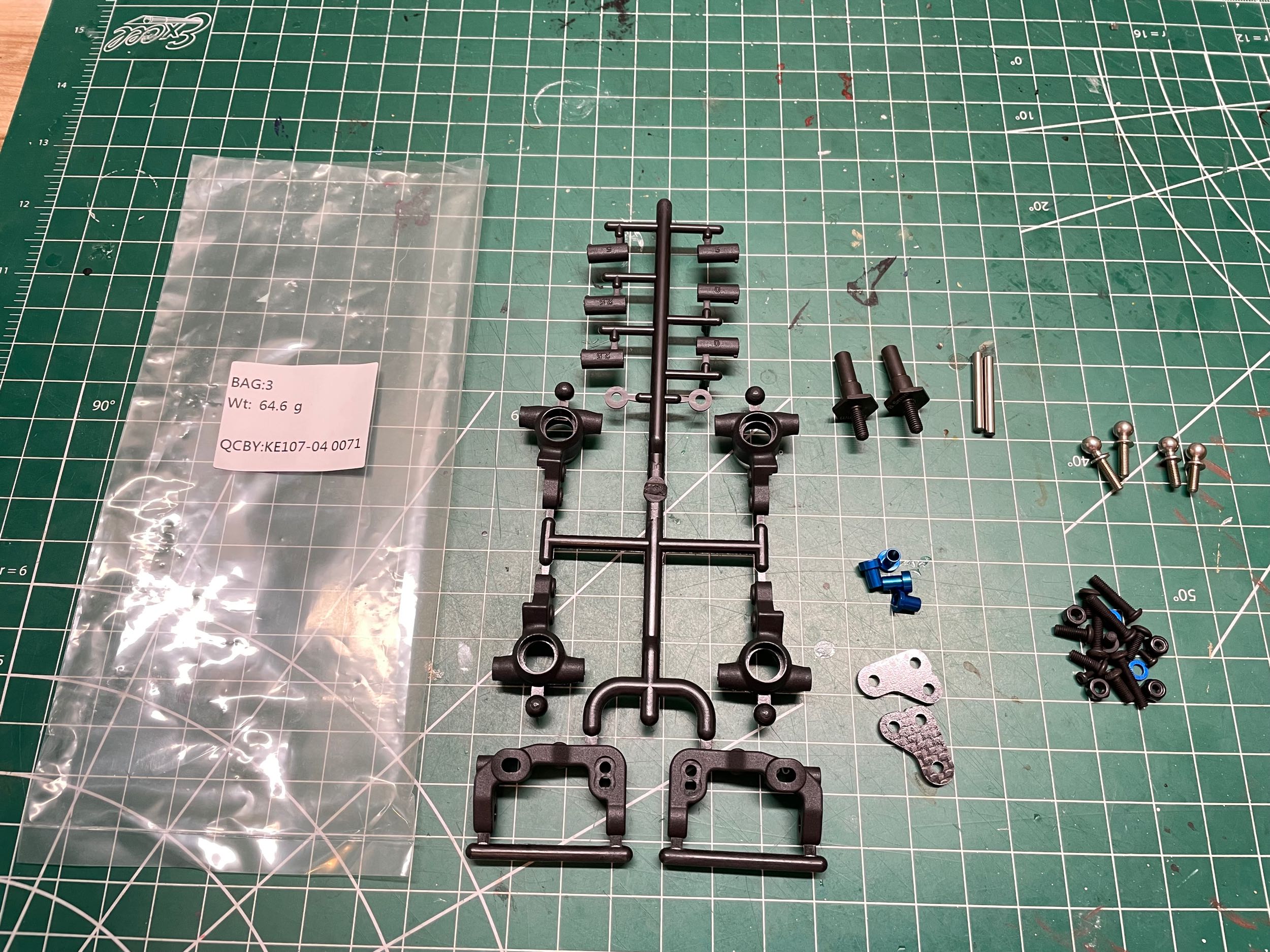
The parts for the remainder of the front suspension
and steering are contained in Bag 3 and shown above. It doesn't
look like much, but there is a lot of adjustability built into those
parts.
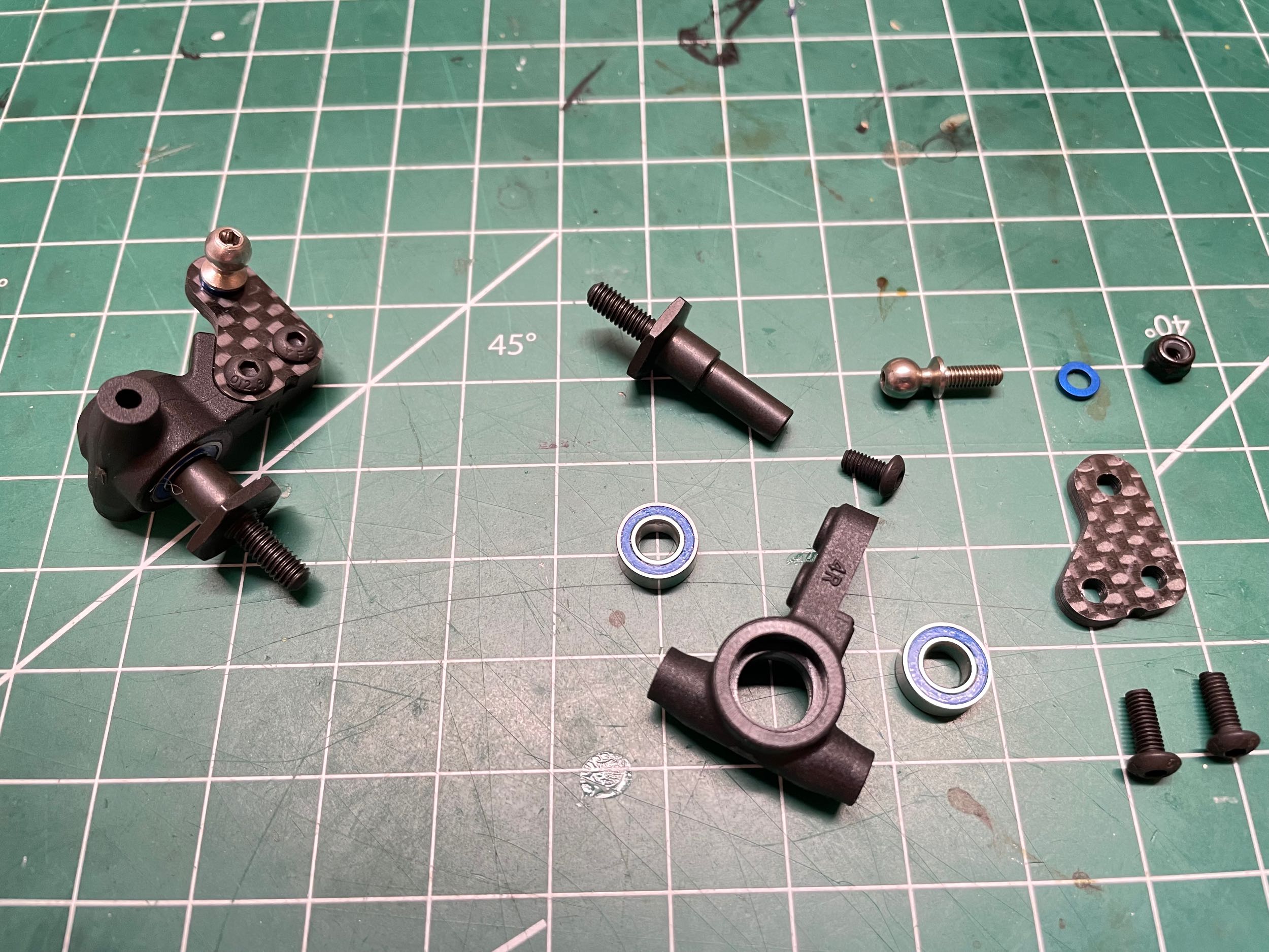
The steering knuckle assembly is shown at left in both
an exploded view and a completed version. The knuckle itself is
plastic and uses two rubber shielded ball bearings to support the
hardened steel axle with 12mm hex. The "8.5mm" printed on the end
of the axle is the offset, not the hex size. Optional titanium
axles are available in case you want them to be much weaker for some
reason. There are two sets of knuckles
included in the kit which vary by having 3mm or 4mm trail. The
standard 4mm trail will give more straight line stability, while the 3mm
trail would offer sharper steering response. The ball stud is
offset from the knuckle using a carbon fiber plate. This plate is
listed in the manual as "+1", but it is not at all clear what this value
of 1 is added to because there is no baseline part to use for
comparison. After some research, it appears that this part puts
the steering ball stud 1mm further inboard compared to a baseline (not
included) part which will serve to provide additional Ackerman
correction to the steering. Apparently this is better for high
grip surfaces (like carpet) which is too bad for me because I will only
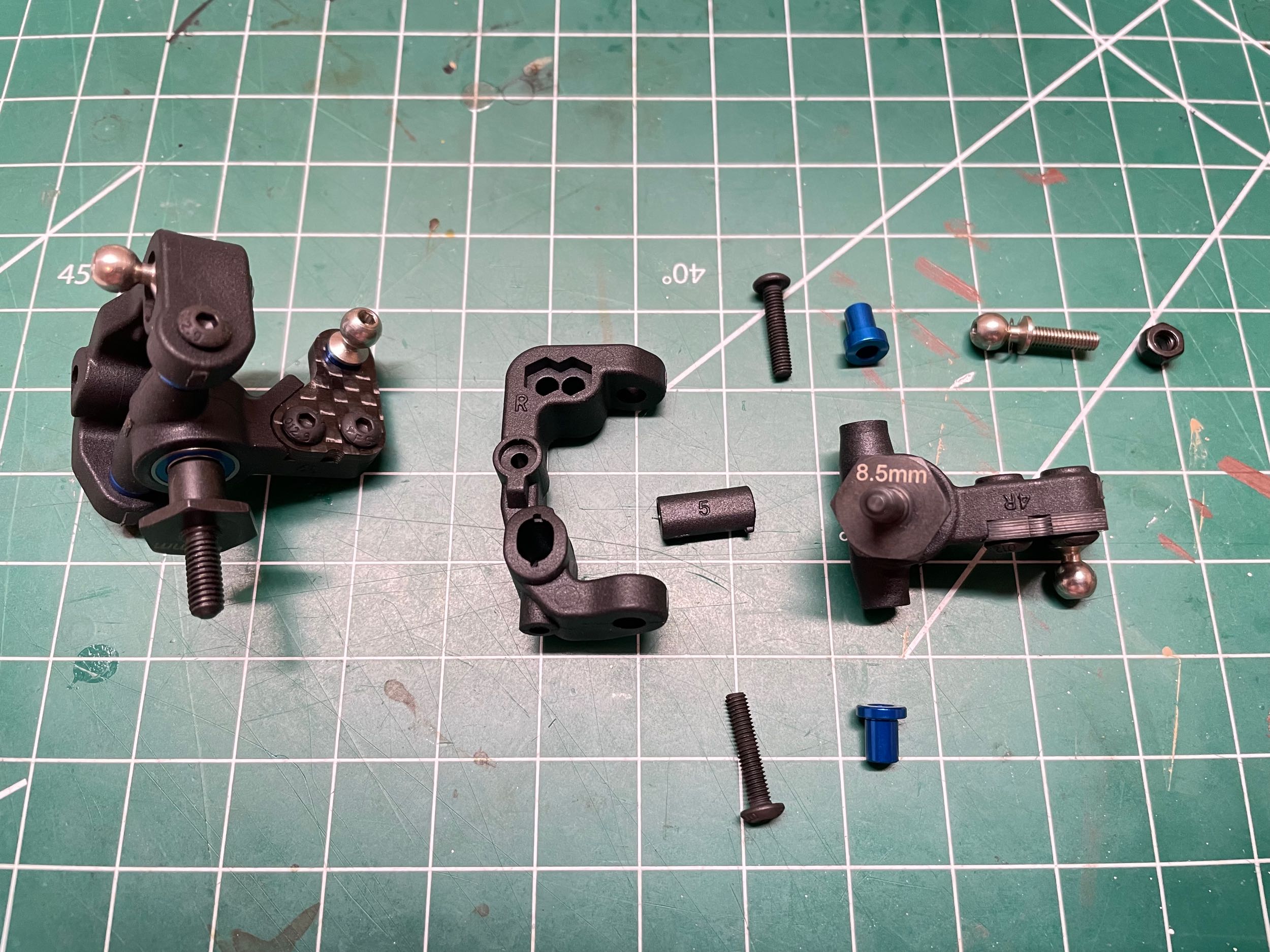
be driving this off road outdoors. The picture on the right shows
an exploded view of the caster block assembly as well as a completed
version. The plastic insert with a "5" printed on it adds an
additional 5° of caster to the 25° which comes from the chassis kickup
for a total of 30°.
It does this by containing an angled hole which will be used as the
pivot axis between the caster block and the lower suspension arm.
Optional 0° and 2.5° inserts are also included. Since they can be
flipped upside down, the amount of caster adjustment they provide can be
positive or negative. Combined with the 25° and 30° options of
the front bulkhead, this means the total caster angle adjustment range
is 20° (25°-5°) to 35° (30°+5°).
There is also a 1mm bump steer spacer under the steering ball stud and
two optional positions for the upper ball stud to adjust kingpin
inclination. The steering angle is limited by contact between the
knuckle and the caster block. A spacer can be installed to limit
the maximum angle.
What does it look like if you make every single
adjustment option the default? It looks like this. The front
steering parts have been installed, but the camber links will have to
wait until later because all the links in the whole kit get installed in
one step near the end. Although you can't really see it in the picture,
there is a 1mm spacer on the hinge pin just behind the caster block
which moves it all the way forward. Moving the spacer to the other
side would slightly reduce the wheelbase.
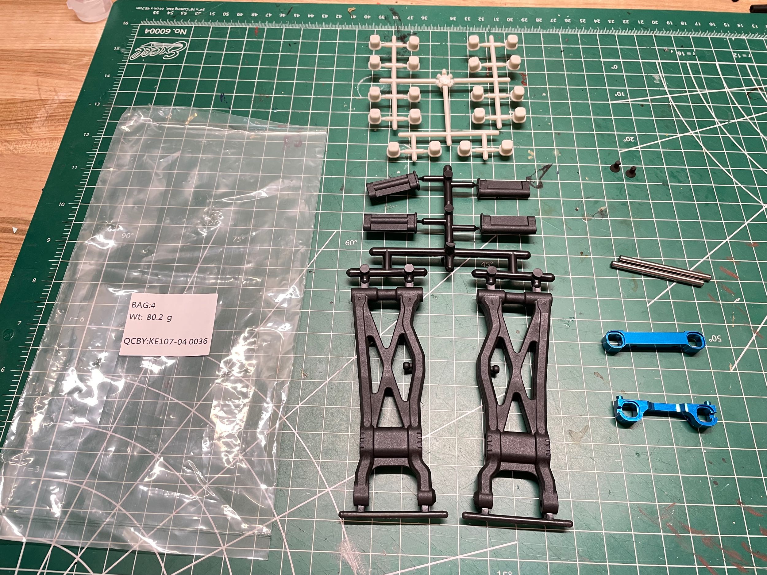
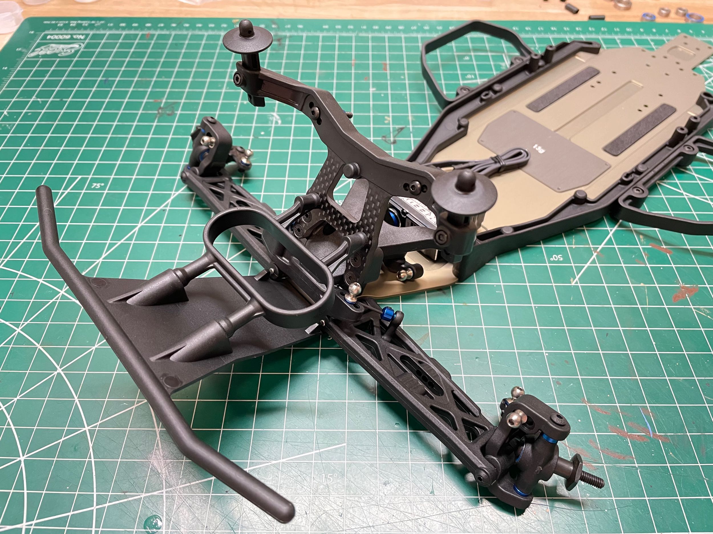
Bag 4 contains the parts for the rear
suspension. Most parts are plastic, but you can see the blue
anodized aluminum suspension mounts.
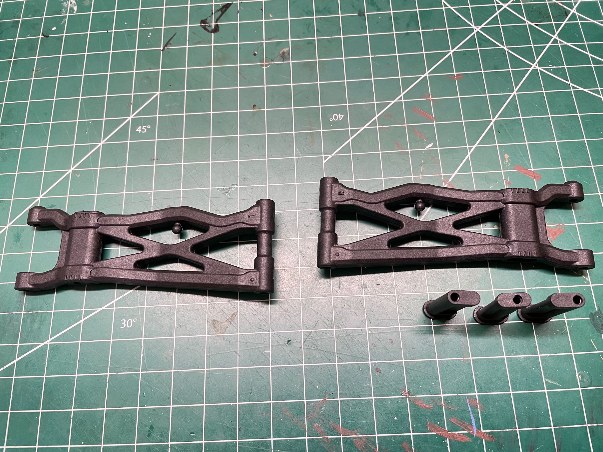
The left and right rear lower suspension arms are
identical. Those inserts you see in the left hand picture are used
to change the position of the lower shock attachment. There are
two types, one with a slightly off center hole, and one with a very off
center hole. Since they can also be flipped, that results in four
position options. The advantage of this system over just having
multiple holes in the arm is that the optional holes can be much closer
together without overlapping and losing strength. The stock
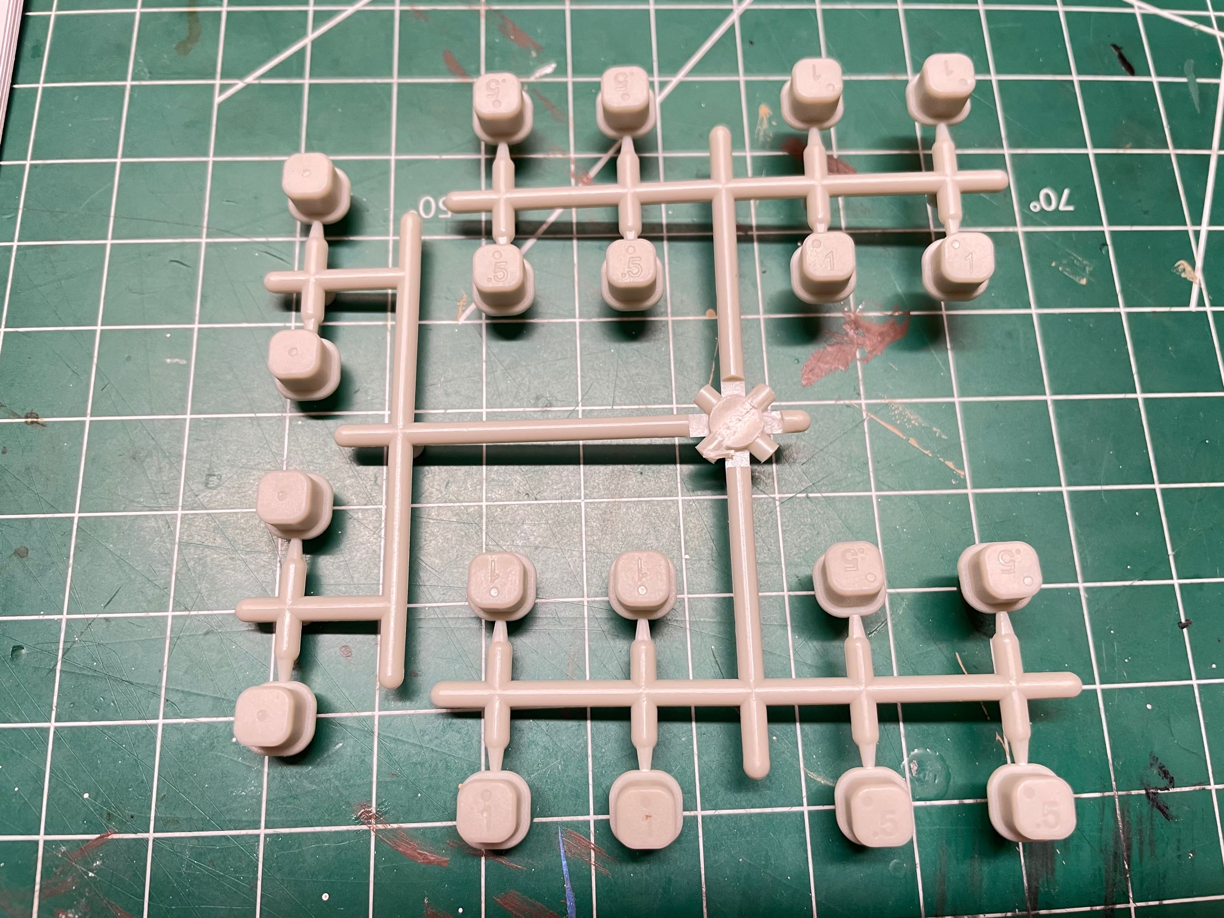
position is the second most outboard option. According to the
manual, the name for those white bits you see on the right is "pill
inserts". Zoom in and you'll see a mark on the back of each
indicating the relative position of the hole in the square. The
hole can be either in the center, 0.35mm toward an edge or a corner, or
0.7mm toward an edge or a corner. Selecting a pair of matching
inserts with holes further inboard or outboard will result in a change
in track width while selecting a pair of matching inserts with holes
further up or down will result in a change in roll center. Mixing
inserts from side to side results in 0.5° or 1° changes in rear toe
angle while mixing them front to back changes the anti-squat
angle. Standard toe angle is 3° but can be adjusted from 1° to
5°. Standard anti-squat angle is 2° but can be adjusted from 0° to
4°.
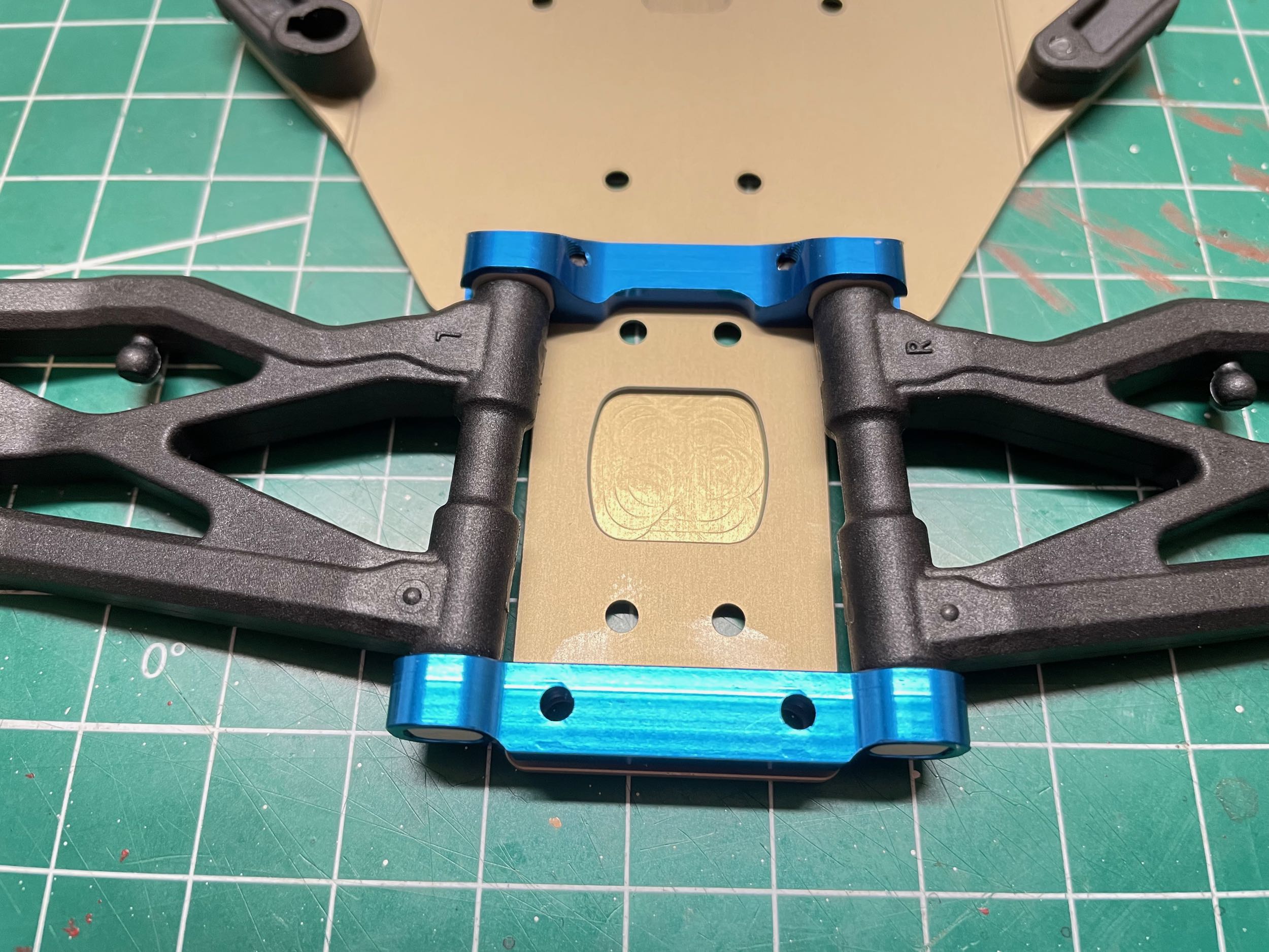
Here one of the rear suspension mounts has been
installed and you can see the default boring inserts with central
holes. The aft suspension mount is wider as you can see on the
right which results in a toe angle even when using the central insert
holes. That milled pocket you can see between the suspension arms
makes space for the teeth of the differential gear allowing it to be
mounted as low as possible.
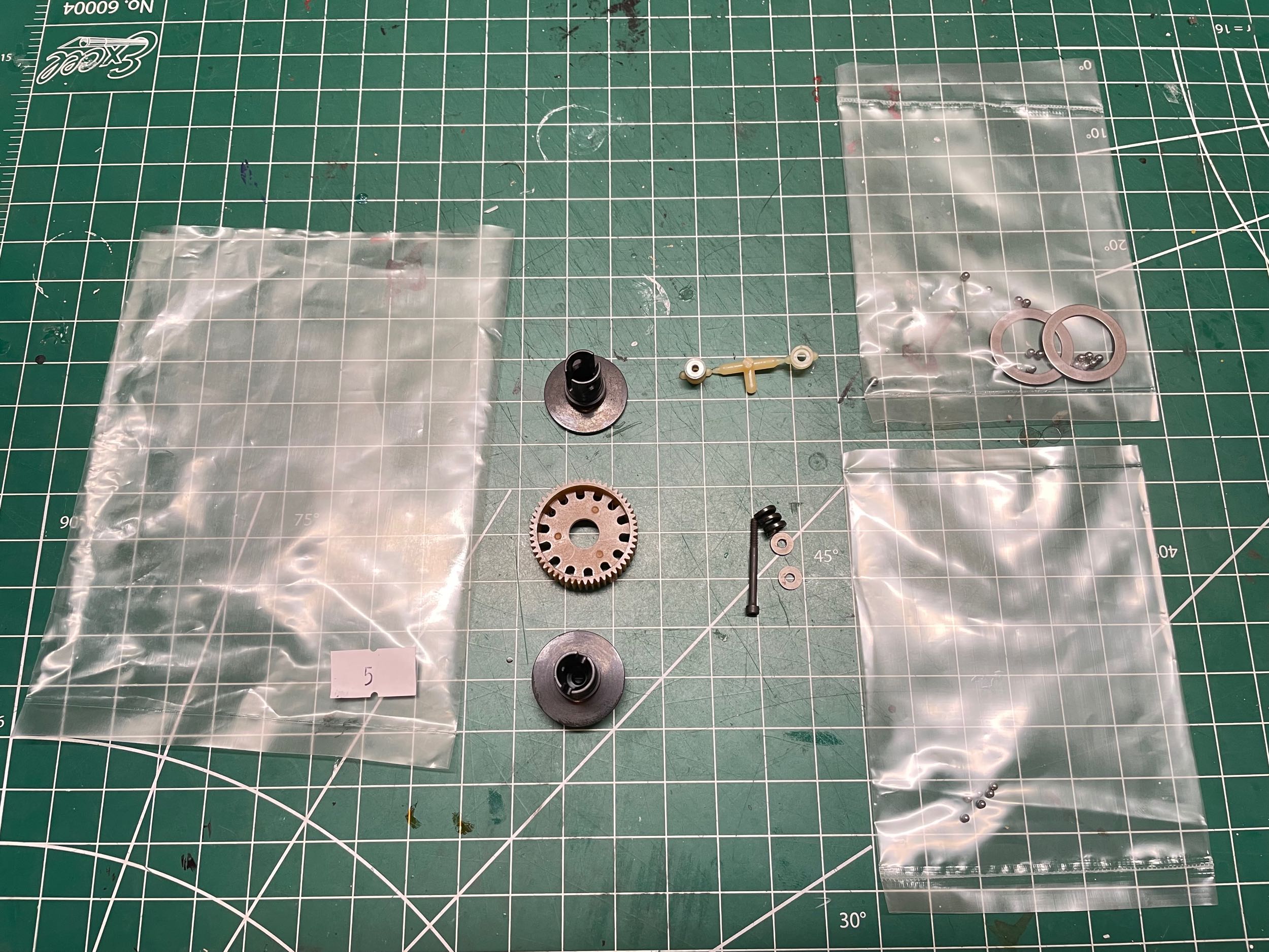
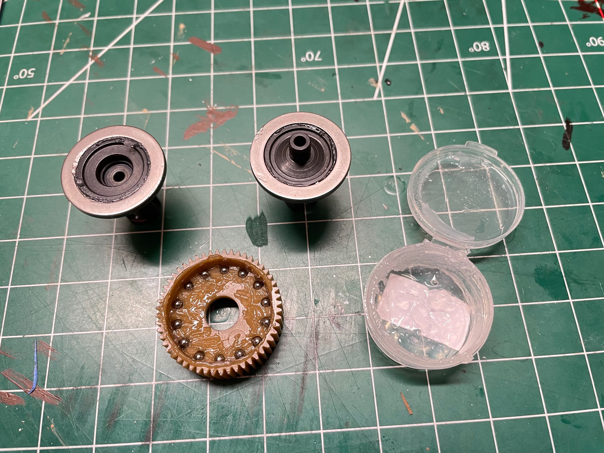
Bag 5 contains the parts for the ball
differential. On the right you can see that it is built with a
total of 14 balls with a diameter of 3/32". There is a tiny
container of clear ball diff grease in the kit. The differential
outer spur gear has 52 teeth.
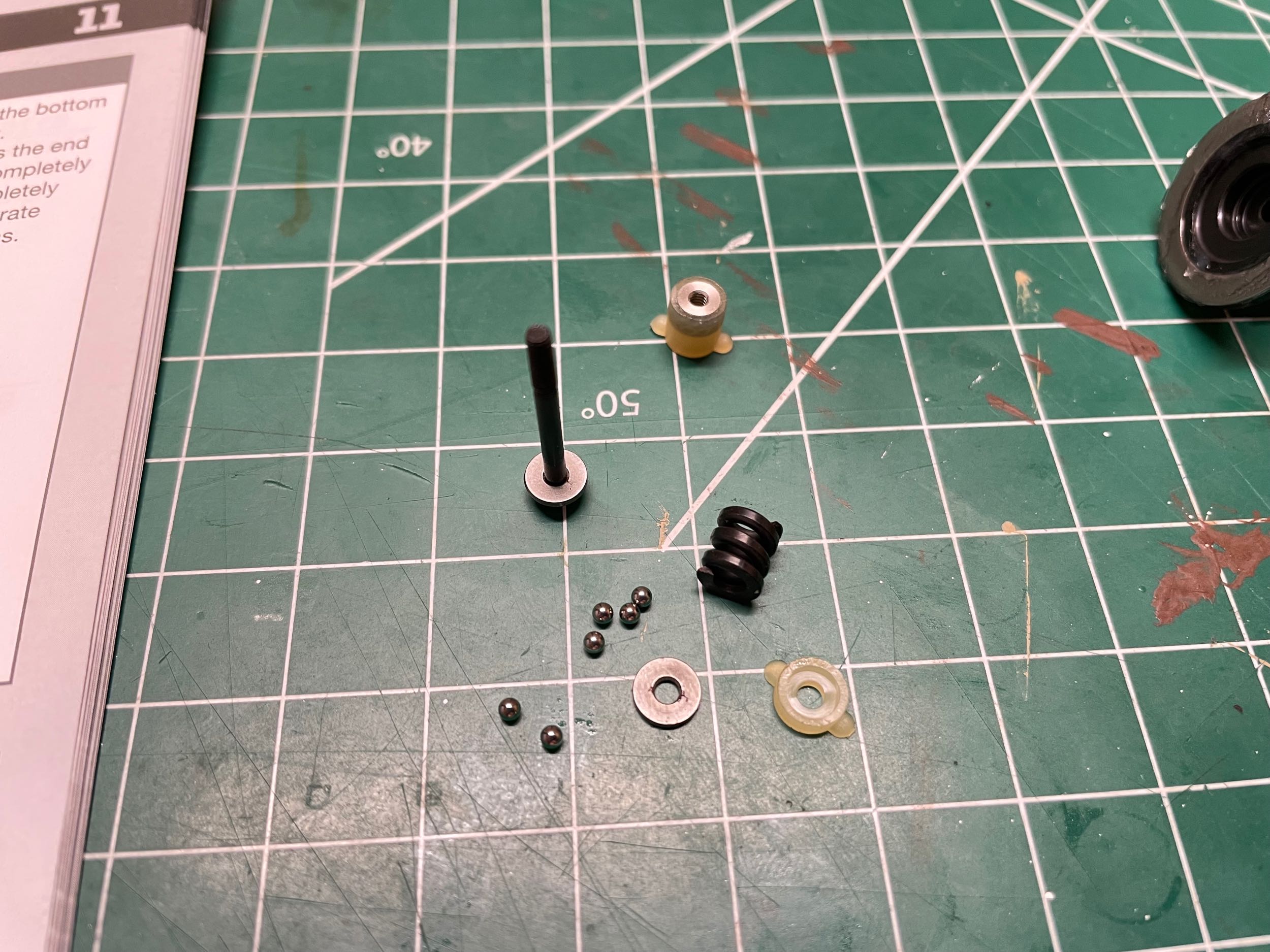
The thrust bearing uses 6 balls of 5/64" diameter that you have to be
careful not to get mixed up with the diff balls since they vary by only
1/64 of an inch. There are no extra balls, so you'll have a real
bad day if you lose any of them. A tiny screw is used to clamp the
diff together across a compression spring allowing easy adjustment.
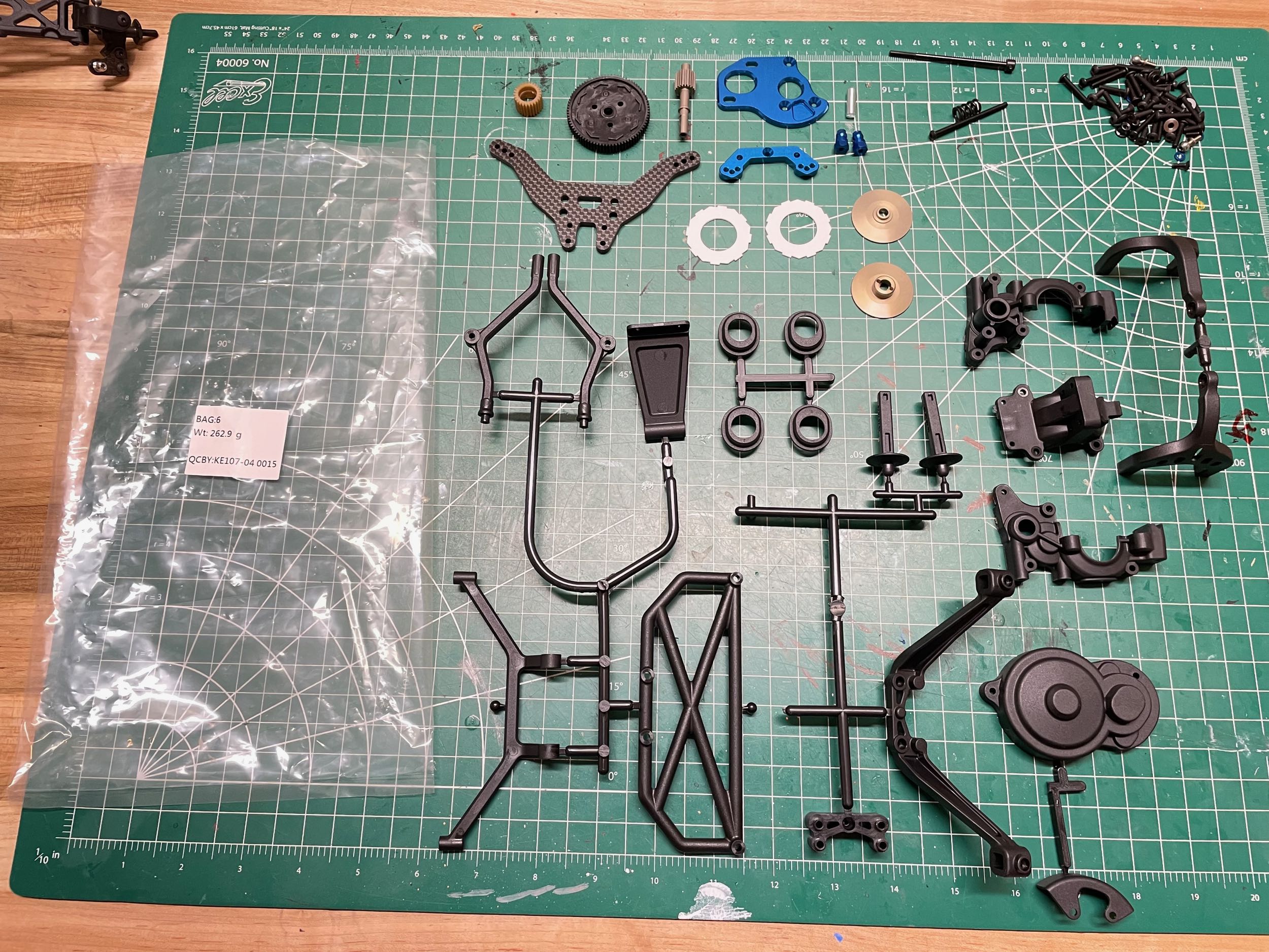
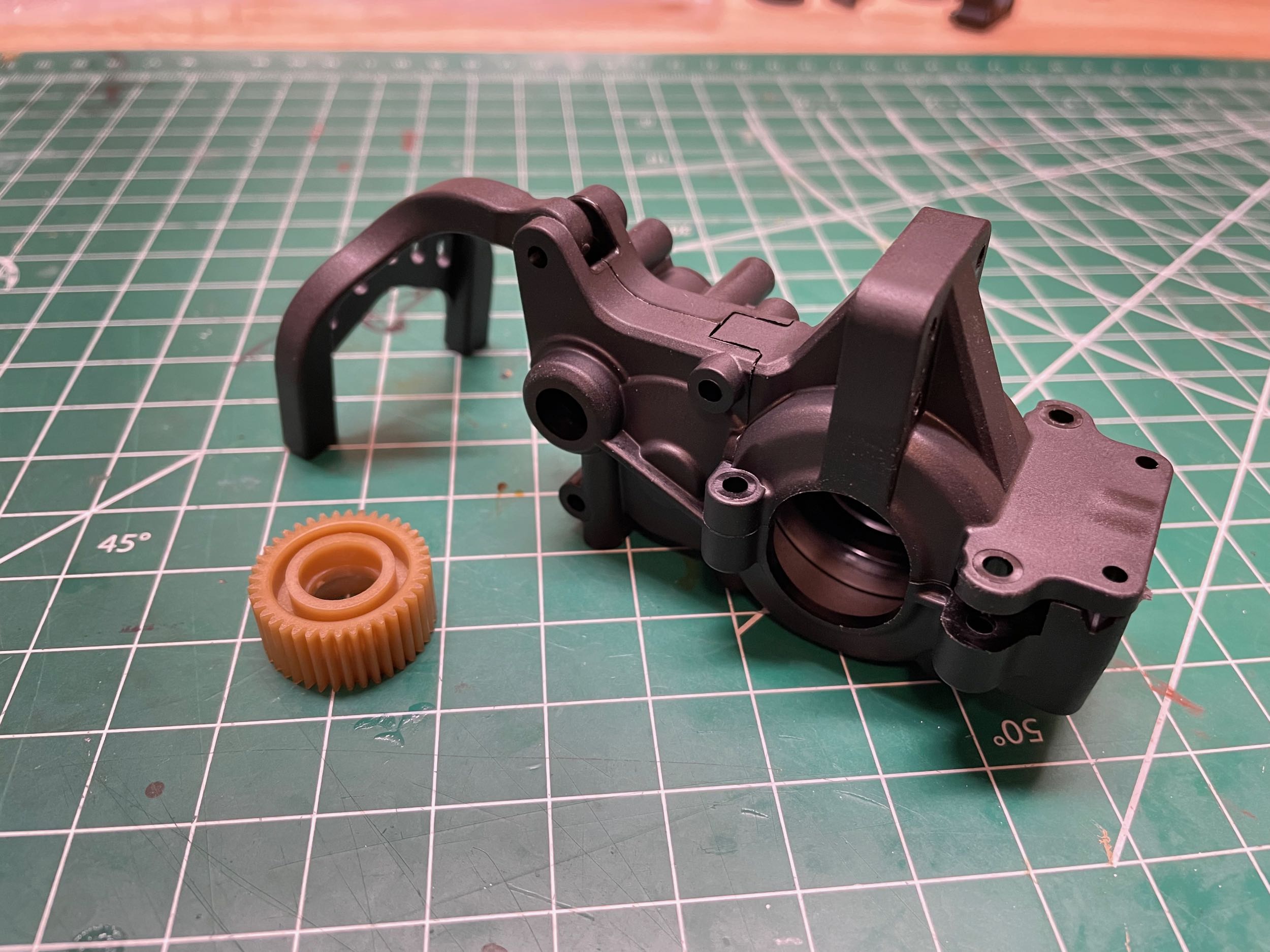
Things just keep getting more complicated. Bag 6 contains parts
for two different version of the transmission, and the names of those
options are not at all helpful. One is called "lay back" and the
other is called "lay down" which pretty much sound like synonyms.
Both have the same gear ratio and low mounted motor height, but the lay
down option has the motor 6mm further forward. The lay back option
is default and the more aft motor position gives you more traction on
loose surfaces. Moving the motor forward with the lay down version
would provide more steering traction instead. To achieve the more
forward motor position, the lay down transmission uses a larger idler
gear. The names of the parts for the different transmission
options are all mixed together in the manual making it very difficult to
figure out which parts to use. For the kind of driving surface I
am going to use (gravel), and standard "stand up" transmission
arrangement would actually be better, but that's not one of the
options. That's what I get for buying a racing chassis and using
it for bashing.
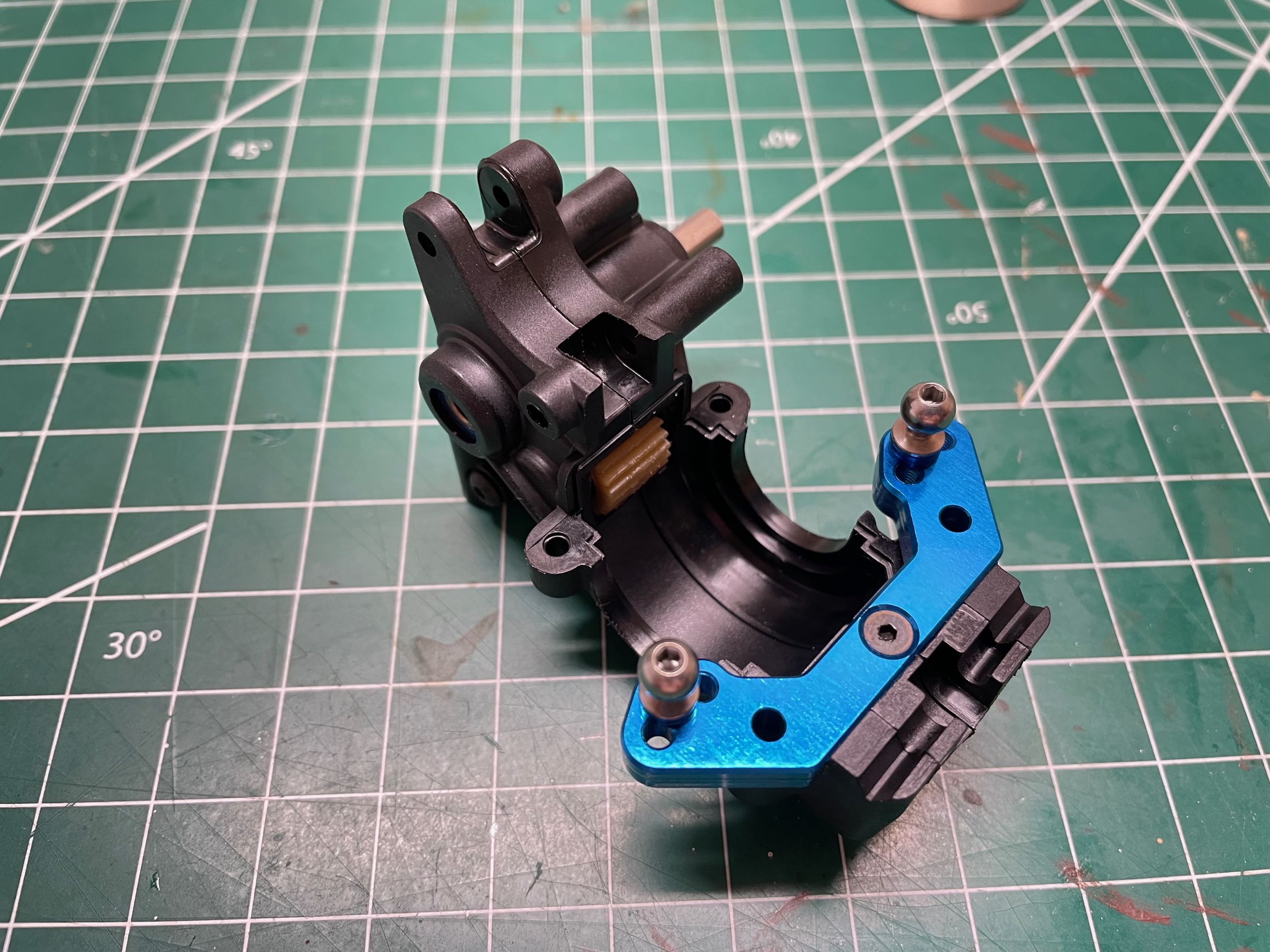
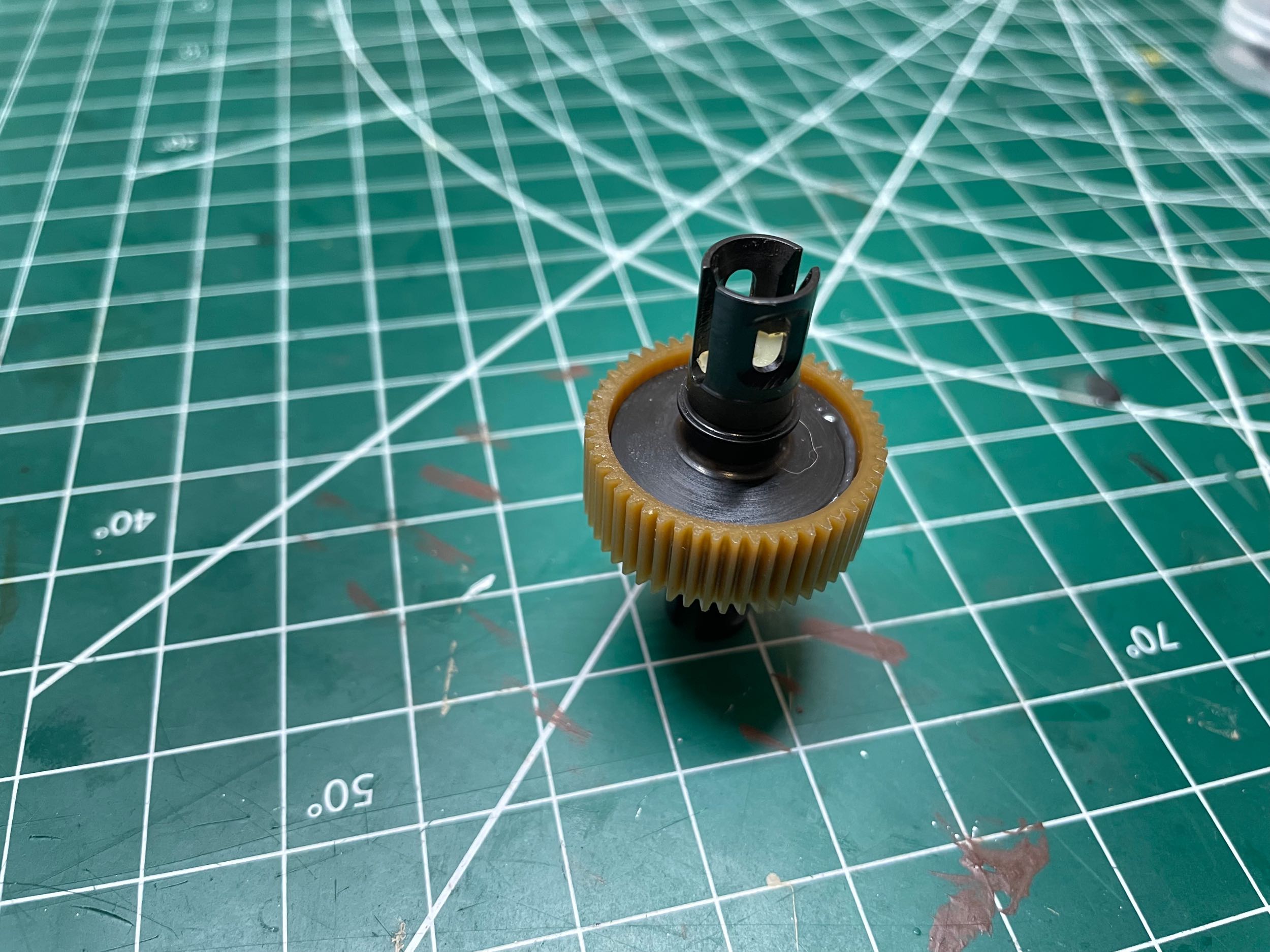
We will be building the lay back transmission starting with the
(apparently) aluminum top shaft and the Nylon idler gear shown on the
left. After the gearbox halves are joined, the aluminum rear ball
stud mount is installed spanning them. There are 2mm of spacers
underneath each ball stud which are installed in the center of three
hole options. There is also a slot for a rear sway bar, but this
is not included in the kit.
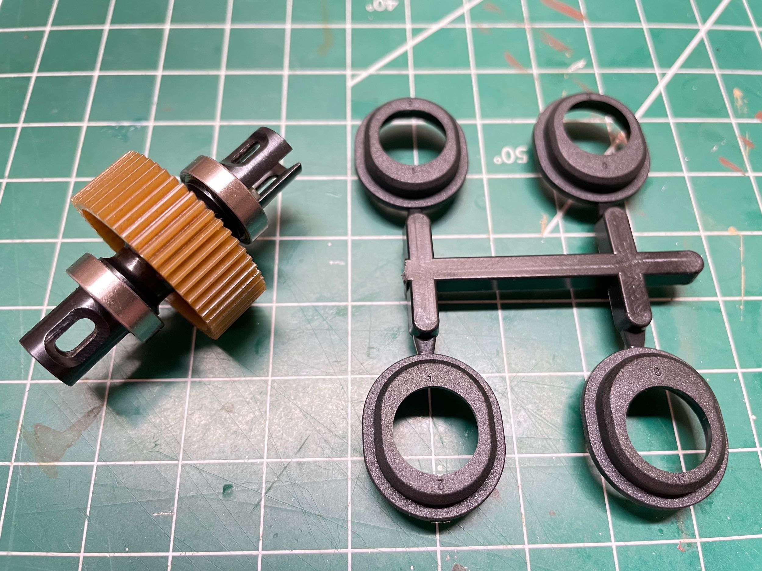
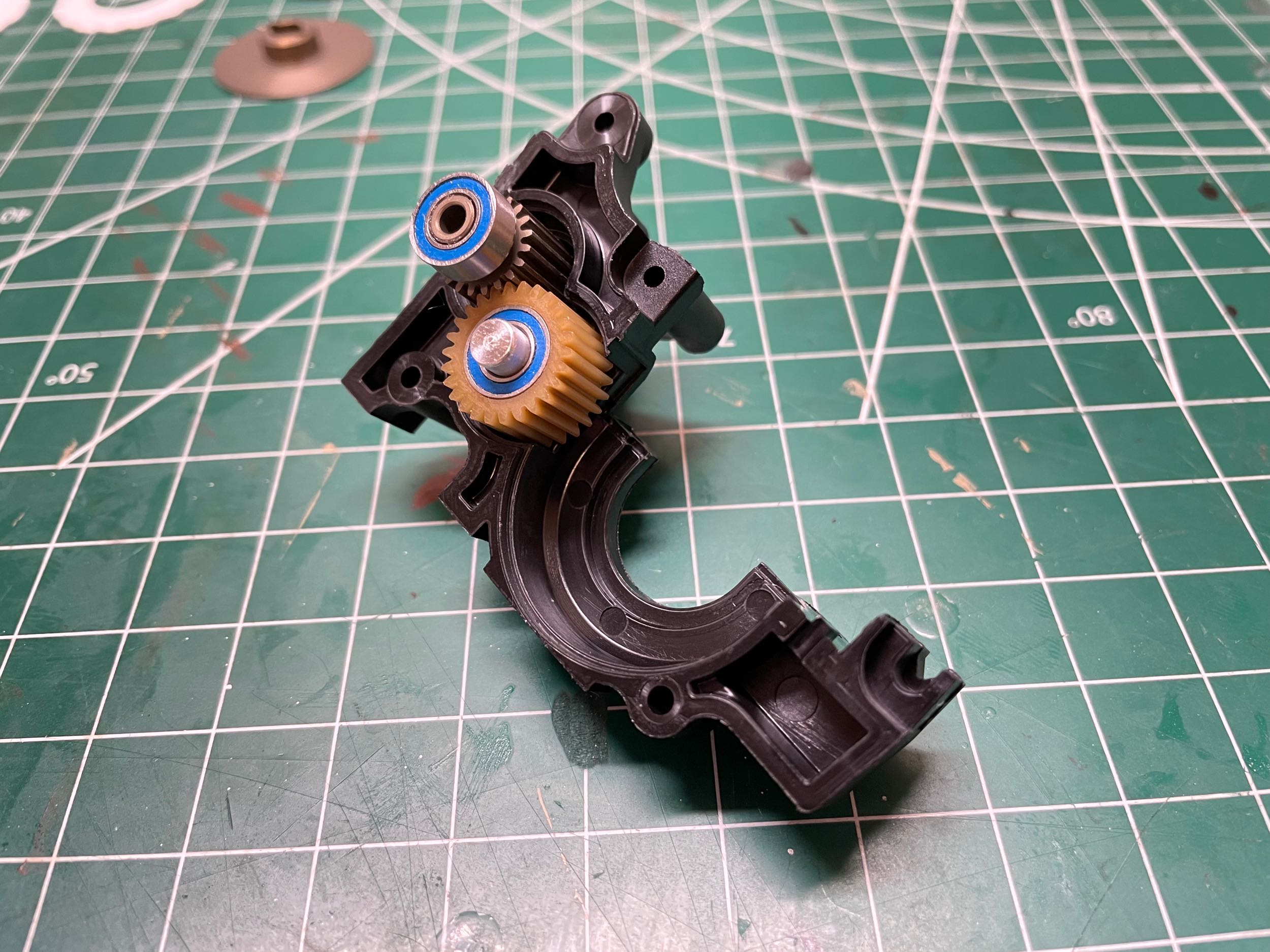
These inserts which support the bearings can be used
to slightly change the height of the differential within the gearbox
housing. It is not at all clear to me why this would make any
difference in how the car performs. The manual claims setting the
diff higher for high grip tracks is a good thing, but does not explain
why. It is probably to keep the drive shafts as close to
horizontal as possible. Moving the diff would also change the way
the gear teeth mate with the idler gear. The extreme high or low
positions would have less tooth engagement, but this must be a minor
impact since there is no adjustment for it. The default position
is the lowest so that's what I used.
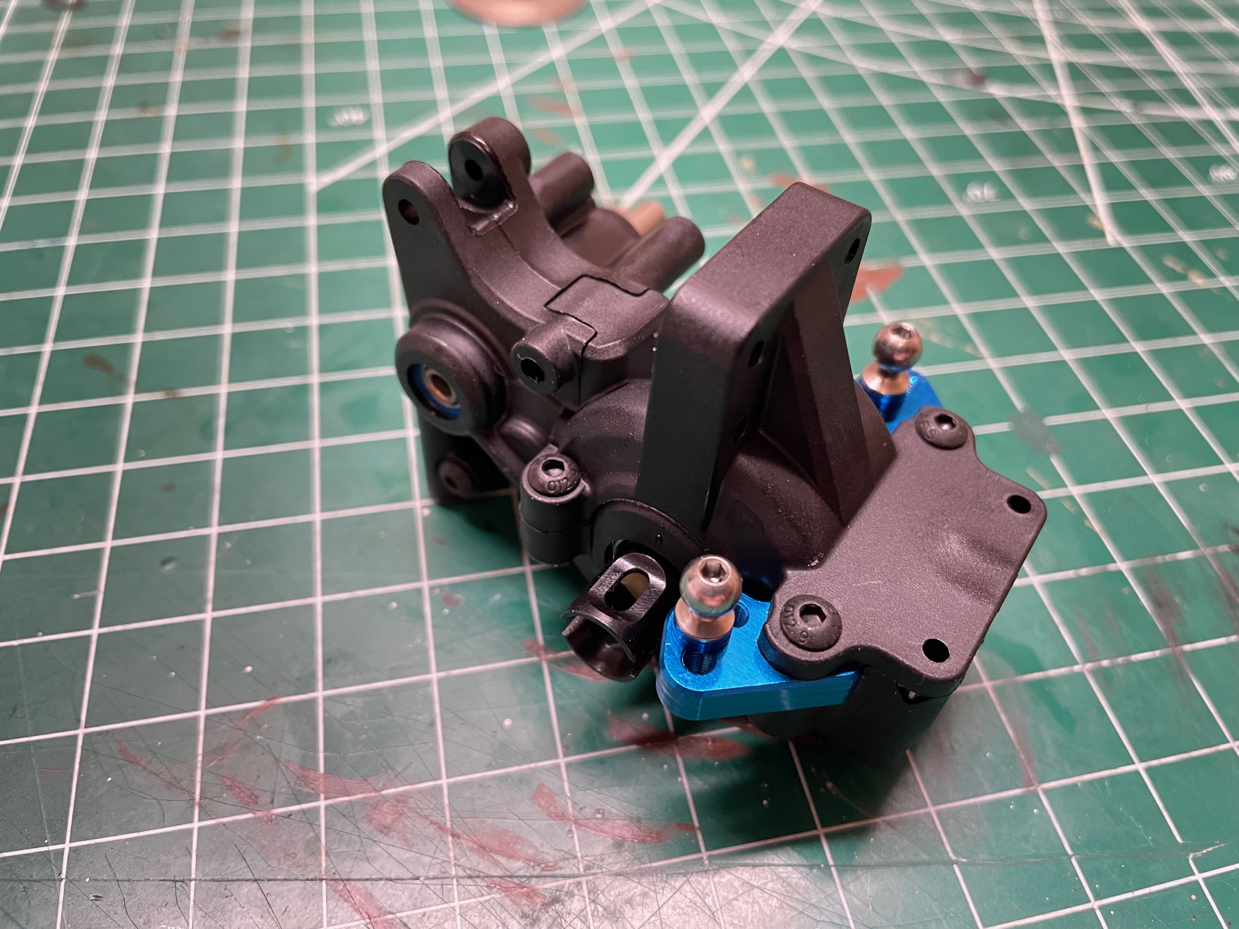
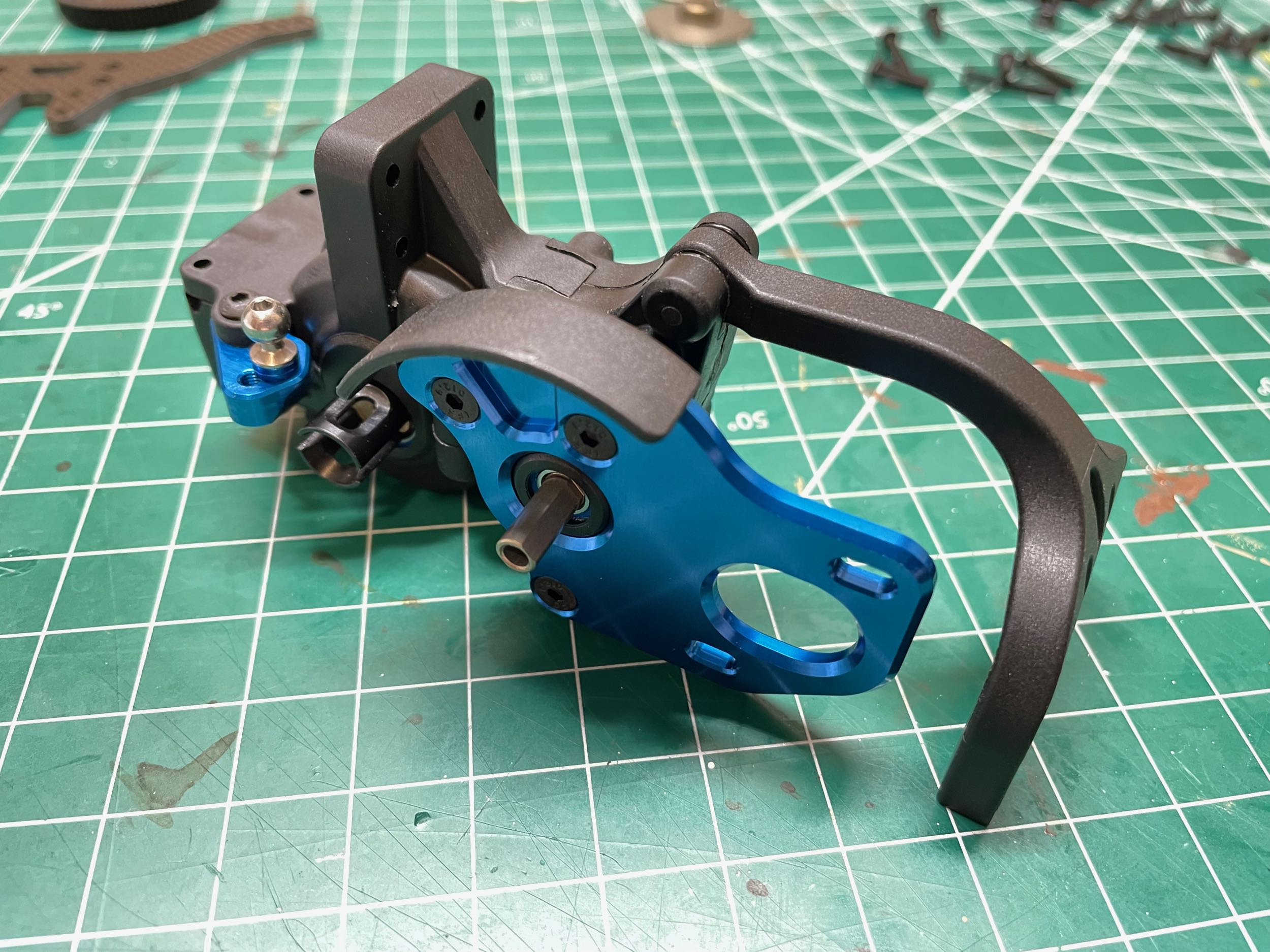
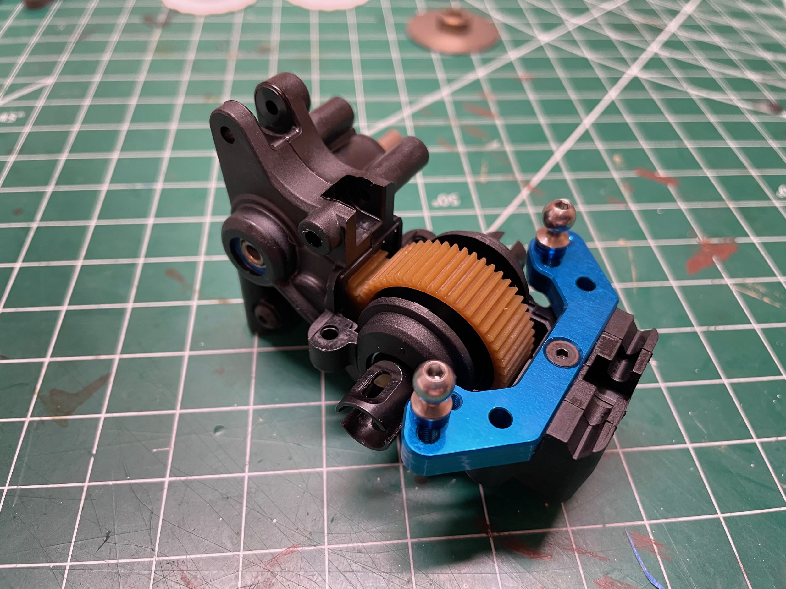
Here the cover has been screwed onto the gearbox
housing as shown on the left. On the right I've attached the
aluminum motor mount plate, the gear guard, and the chassis brace which
will help stabilize the gearbox on the chassis plate.
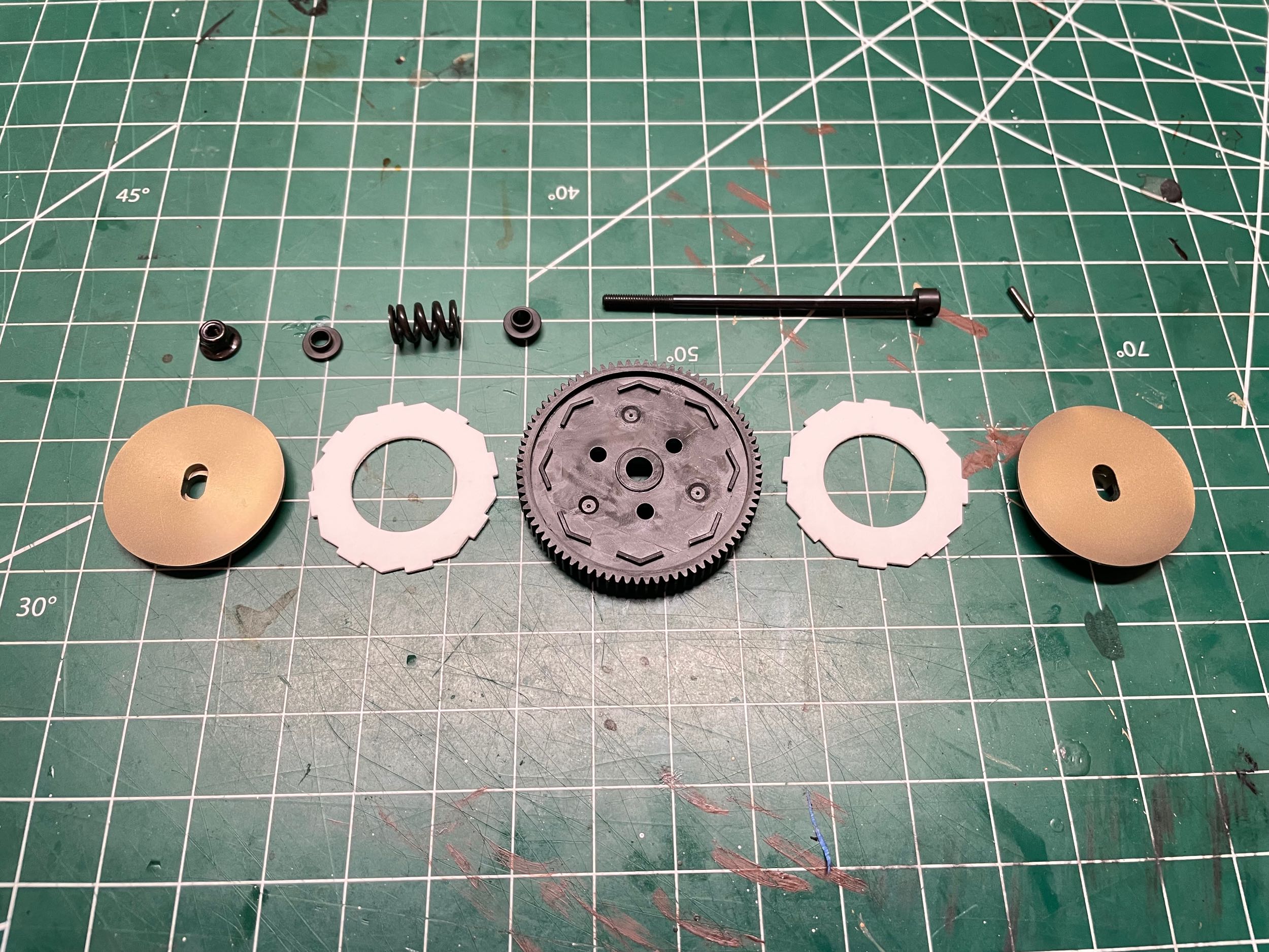
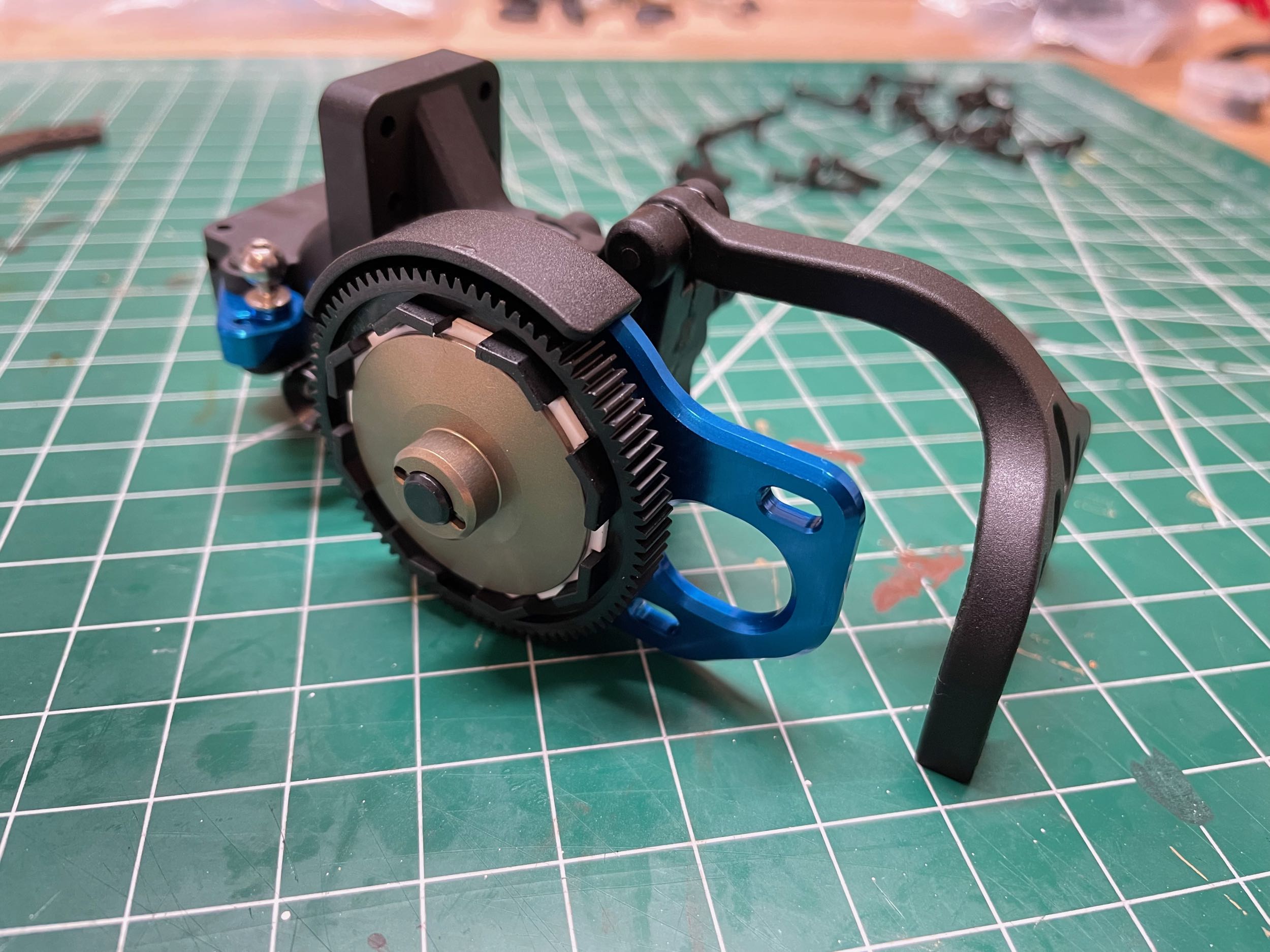
The slipper clutch uses two friction pads, one on
either side of the spur gear. The friction pads are keyed to the
spur gear and spin with it, but the gear itself is not keyed to the
shaft it rides on. Rather, the aluminum slipper hubs have slots
which key to the shaft. So when torque is introduced into the spur
gear teeth from the motor, the only path into the shaft is through the
hubs via friction. Thus, the clamping force across the slipper
determines the maximum torque that can be transmitted. This is a
high power model, so the slipper needs to be pretty tight. It
protects the gears and axles from very abrupt changes in torque.
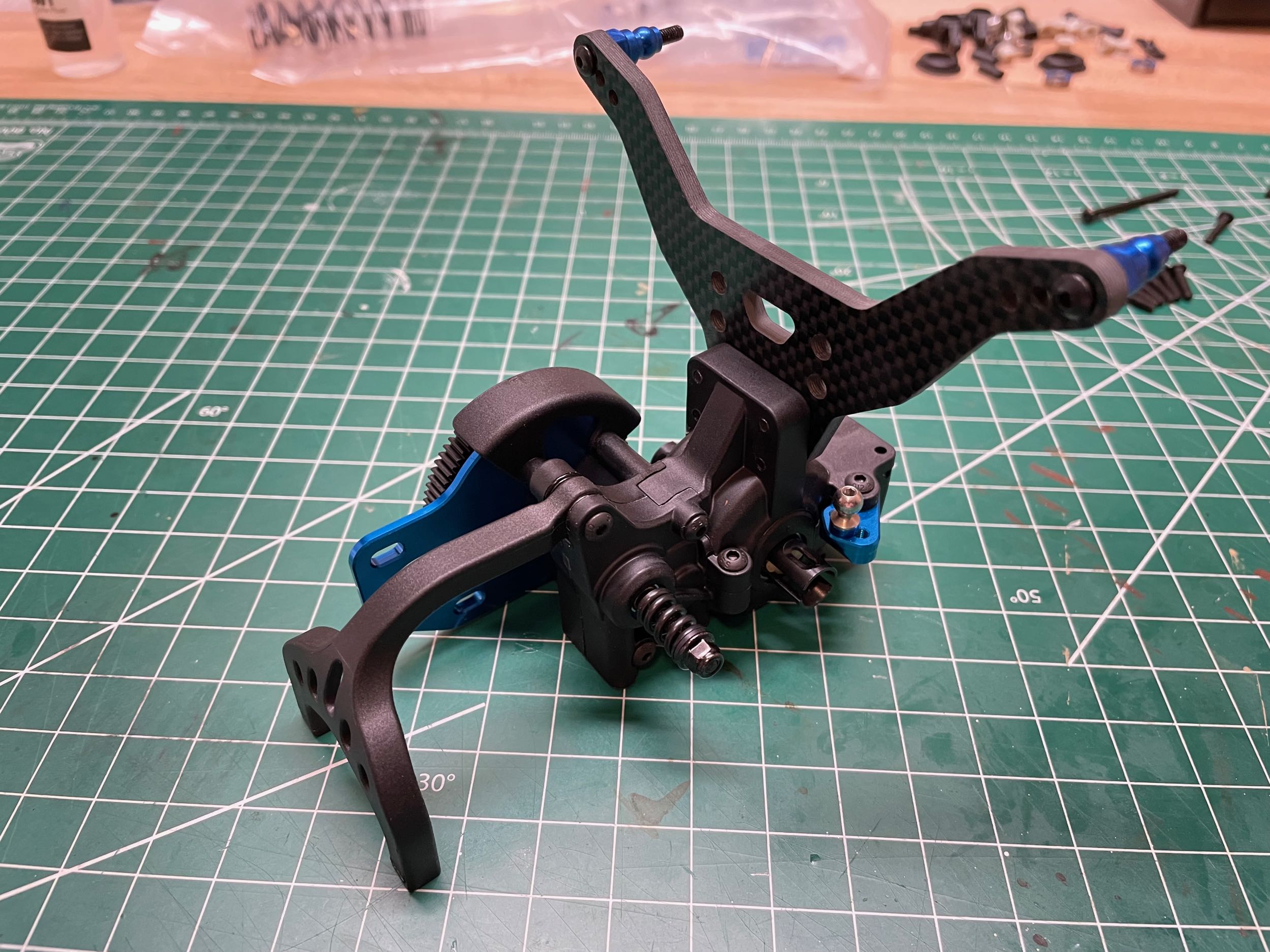
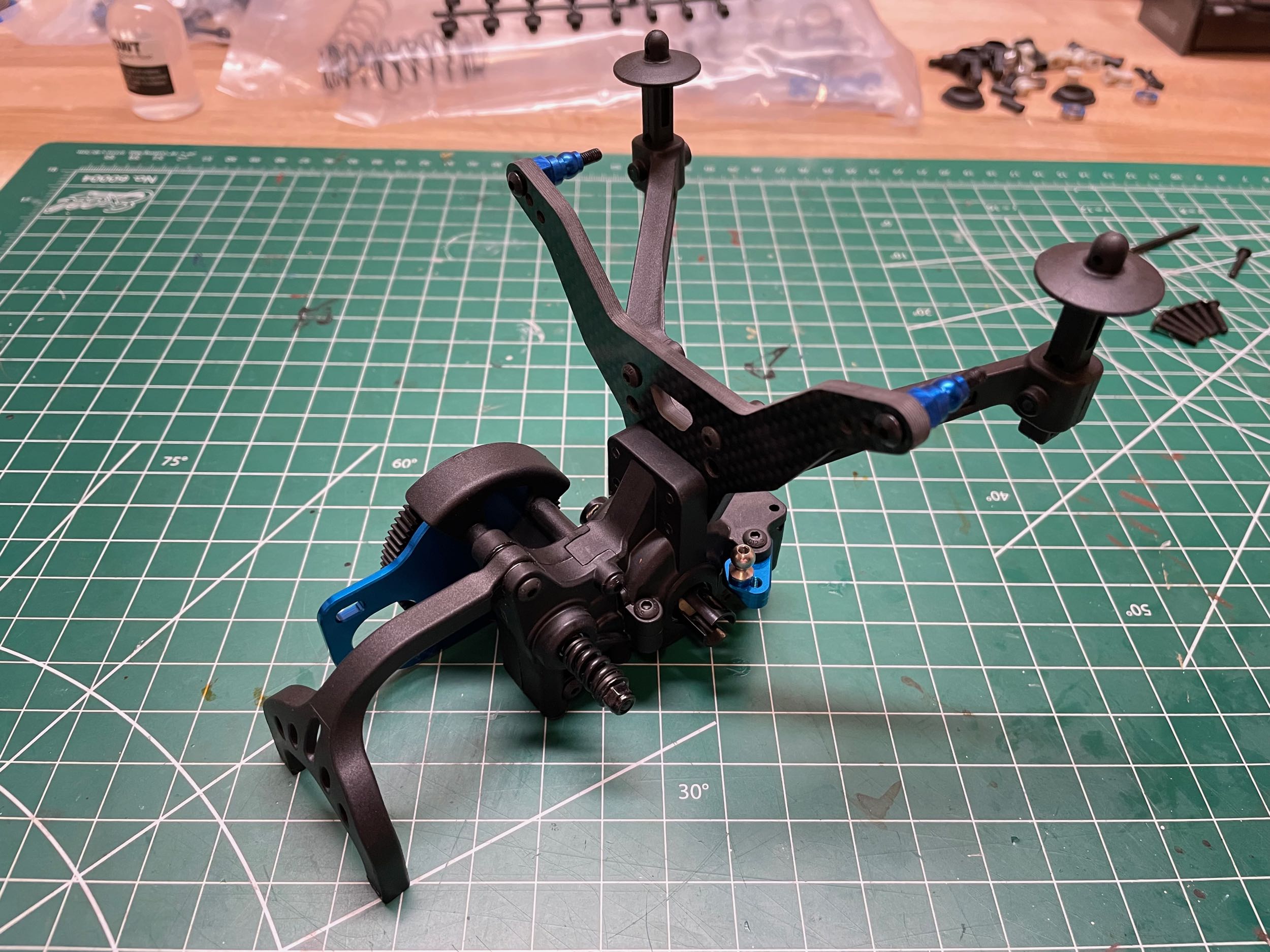
Now we can make the whole assembly more gangly by
adding the 4mm thick carbon fiber shock tower. It seems to me that
the plastic mounting interface to the gearbox housing is a bit small
for a tower this large, but so far it seems to work. There are
three hole options on either side for the upper shock support (the
center hole is default). On the right I've also added the rear
body posts which cantilever quite far behind the shock tower.
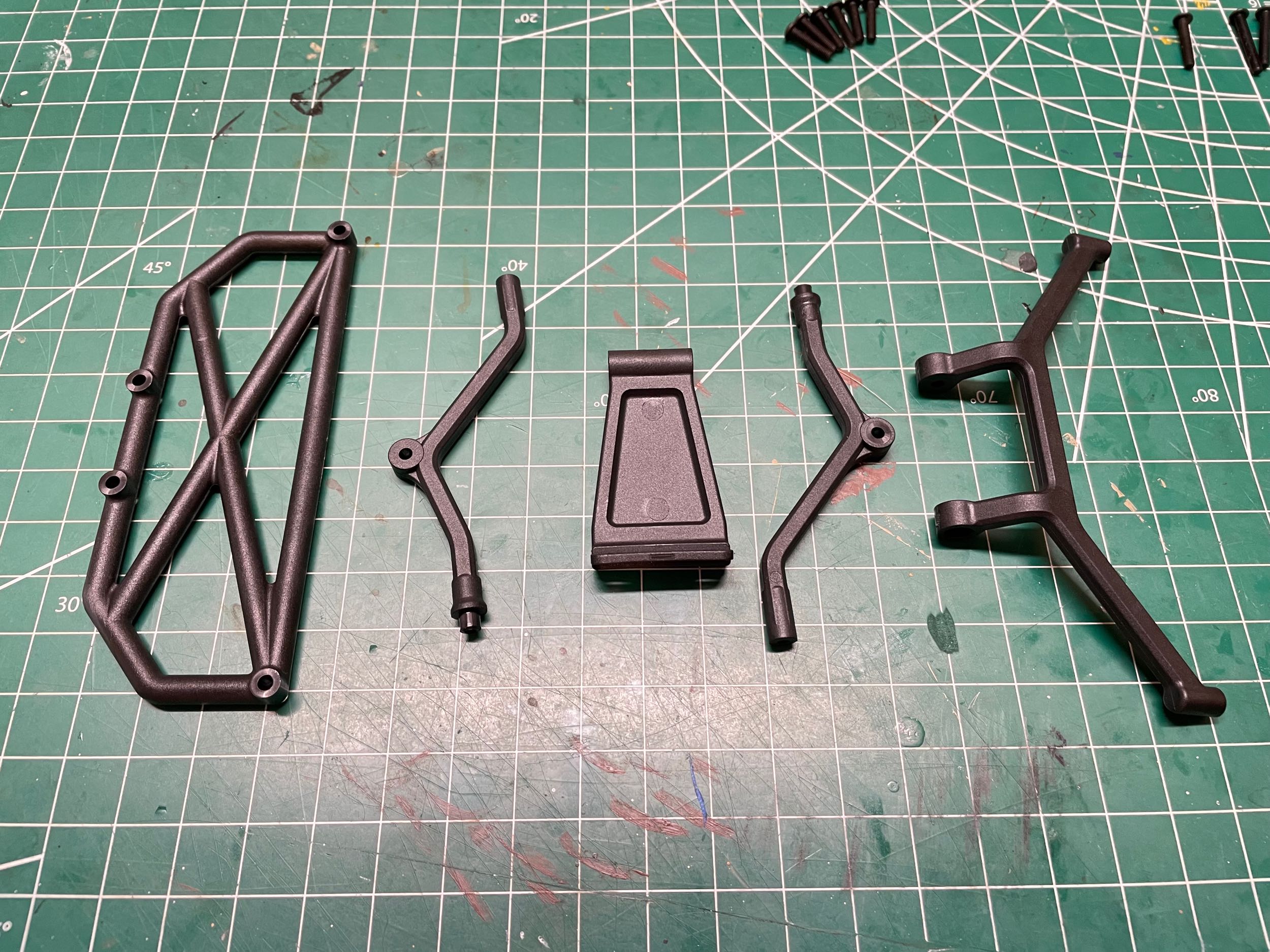
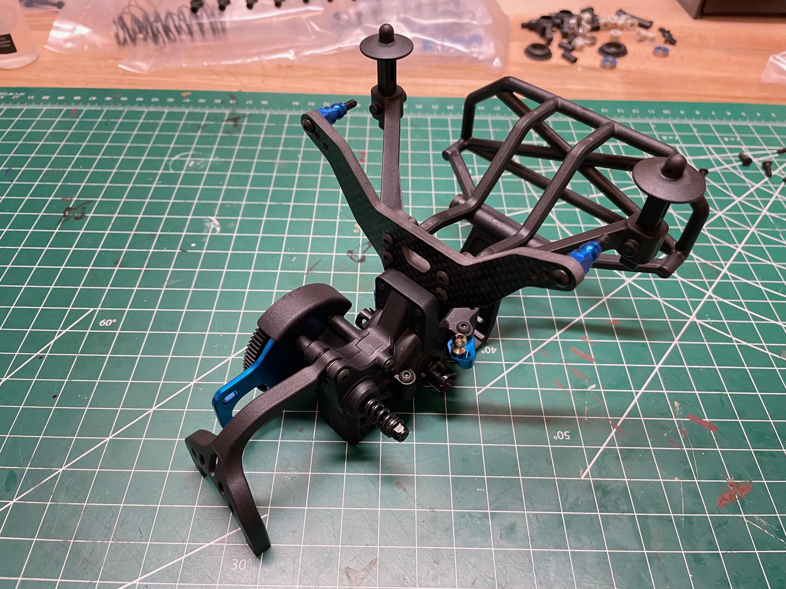
Let's add even more parts before connecting this to
the chassis. The final bits shown at the left are for the rear
bumper. Unlike the front bumper, the rear doesn't have a big
flexible loop to absorb impact. it is pretty sturdy being braced
in multiple directions.
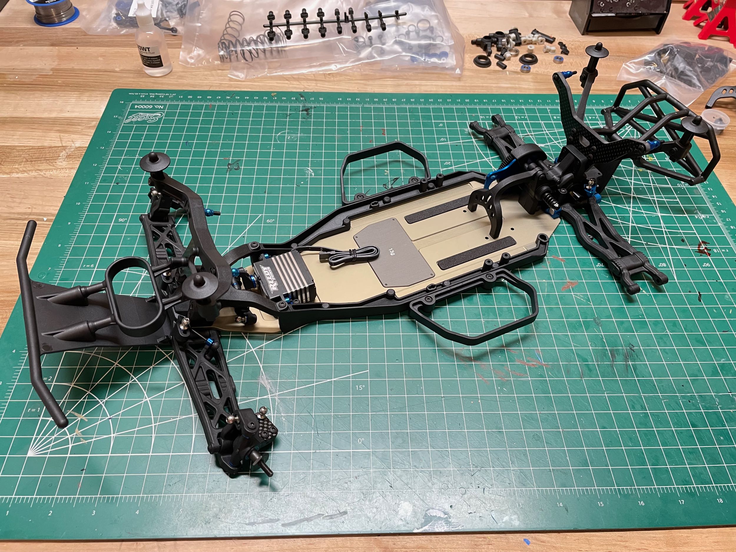
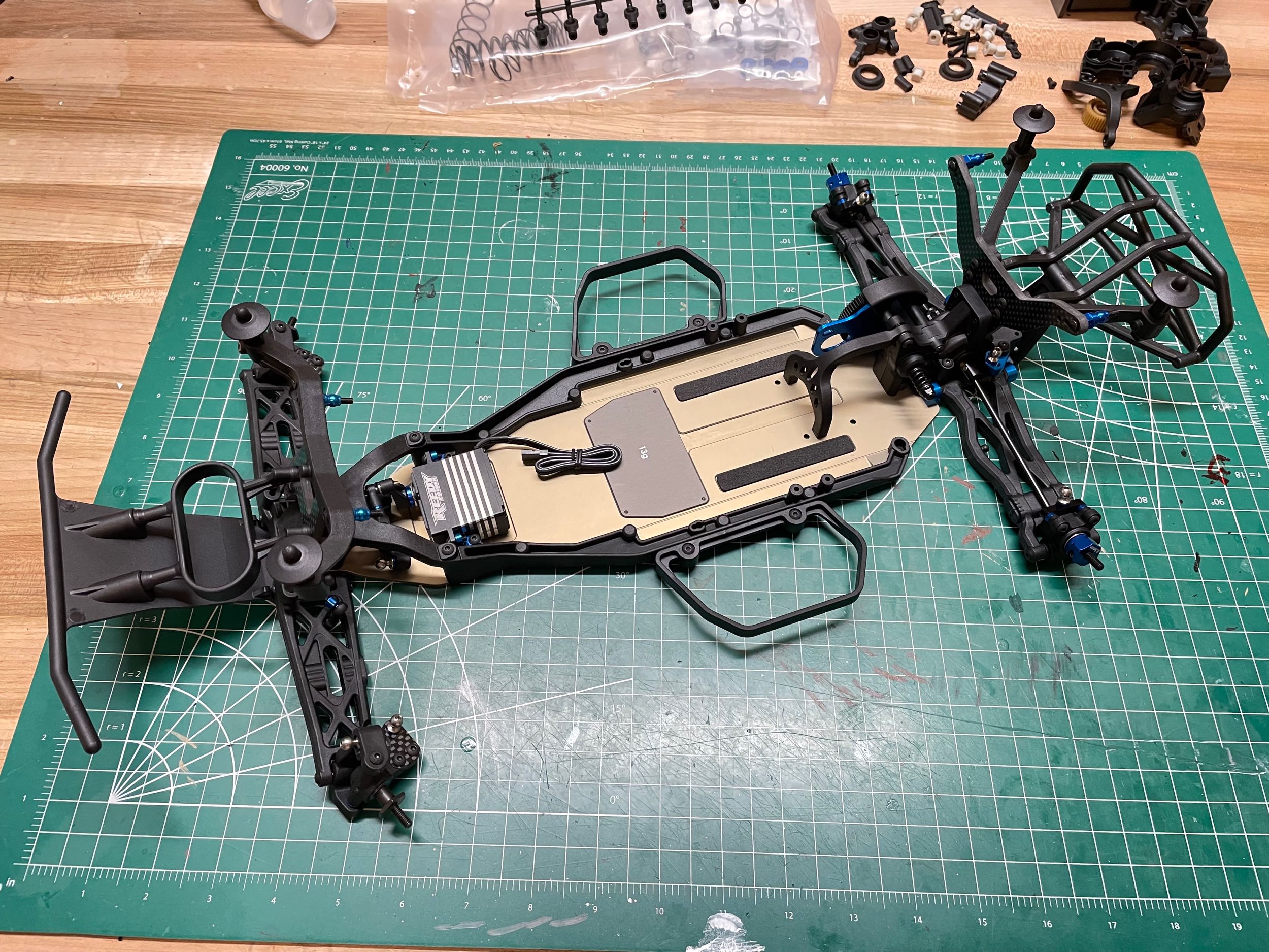
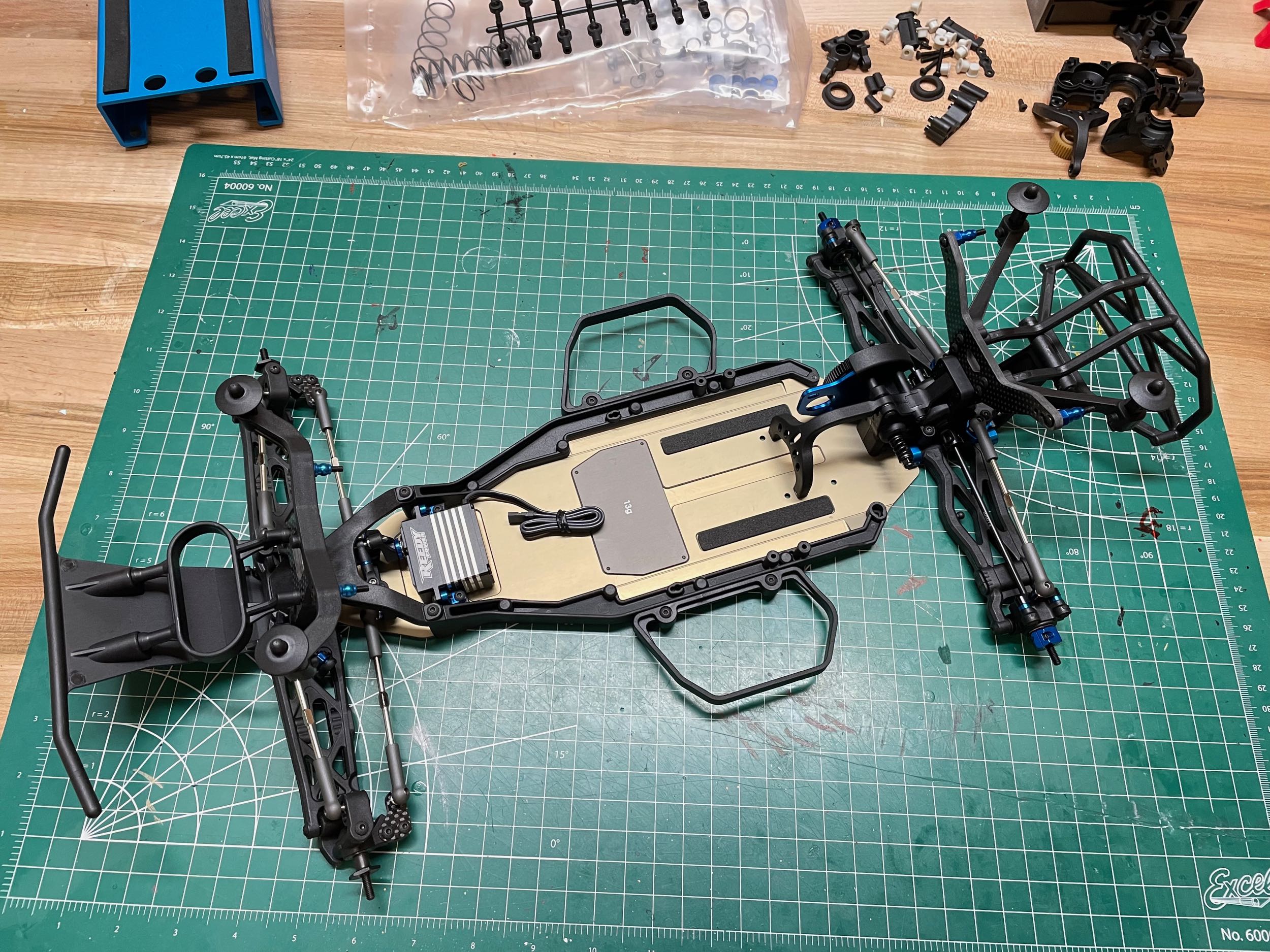
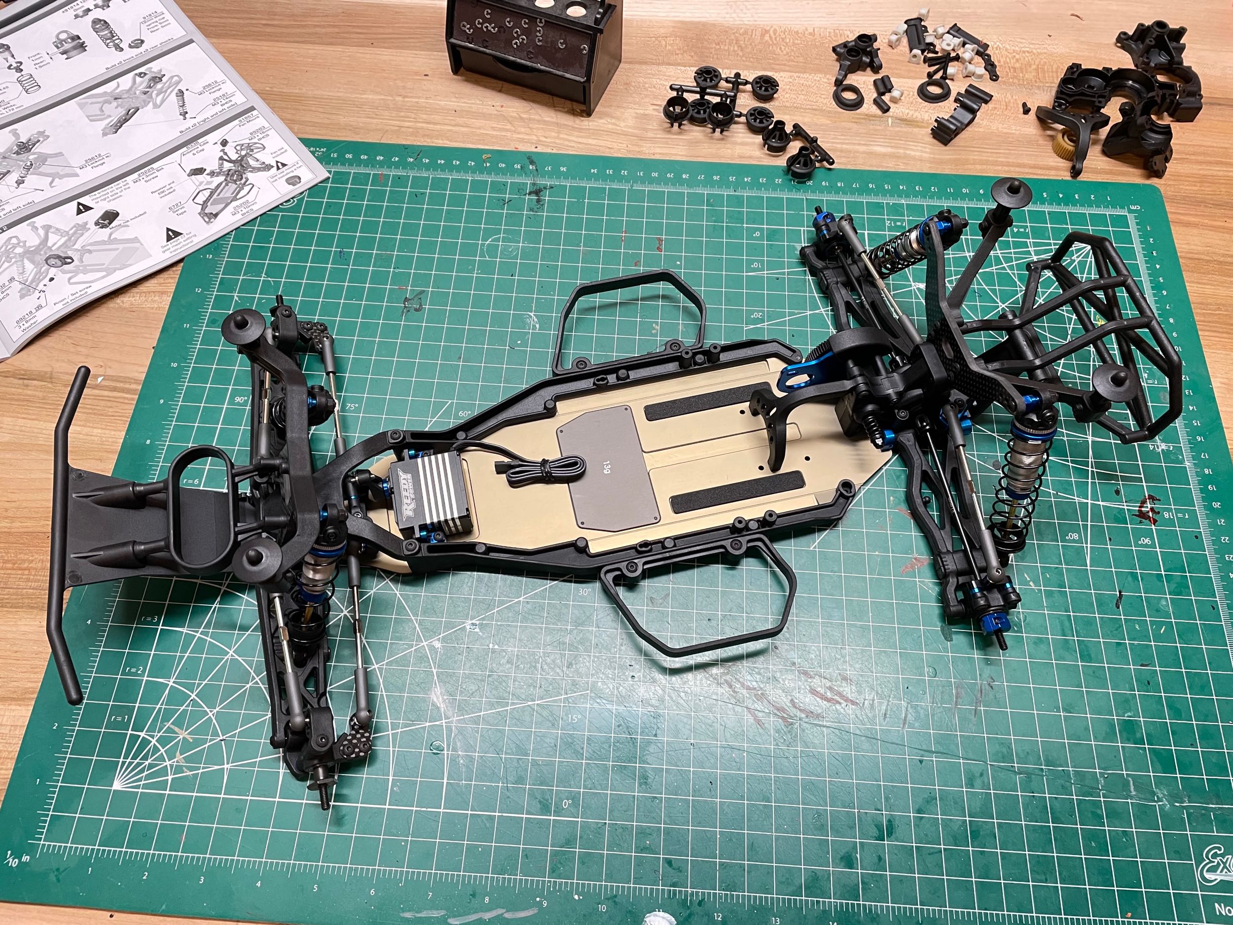
At long last the rear gearbox assembly can be attached to the chassis
resulting in the nearly complete version shown at left. The photo
on the right shows the unused parts left over which are for the "lay
down" transmission option.
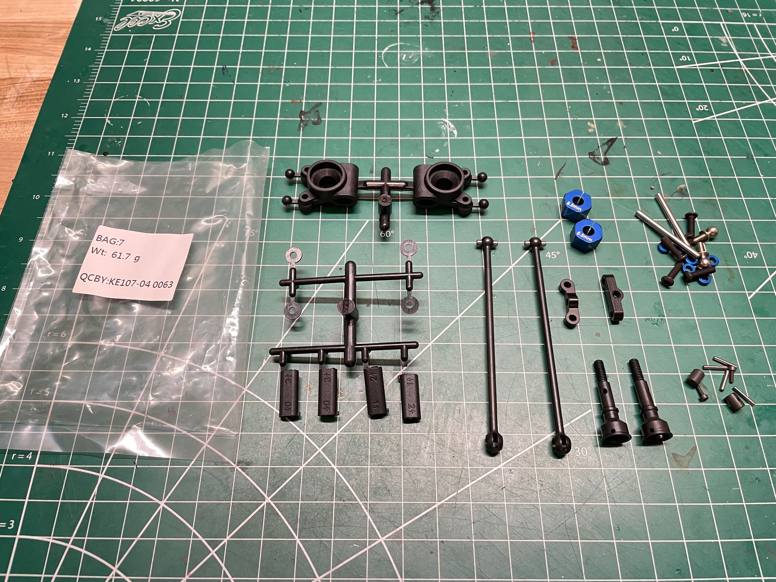
Bag 7 contains the parts for the rear hubs and axles. There are
not very many parts here and not as many adjustment options as for the
front hubs, but still plenty of complexity.
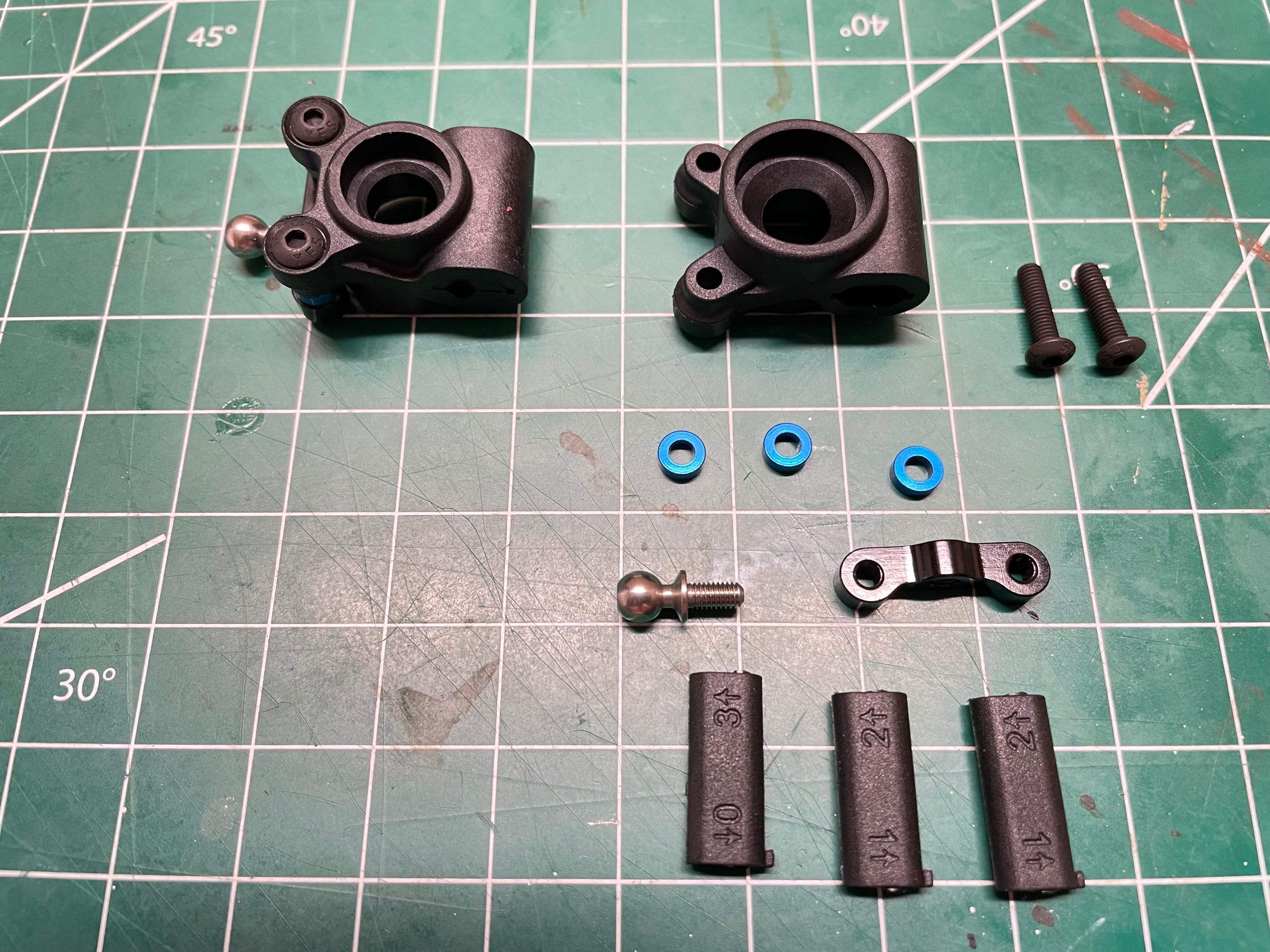
The inserts shown in the photo on the left have holes either 1mm or 2mm
off center which can be flipped, thus offering four different
options. The hinge pin will pass through this hole and control the
position of the hub relative to the lower suspension arm. There
are a pair of 2mm spacers positioning the ball stud for the camber link
in the lateral direction, and another 2mm spacer in the vertical
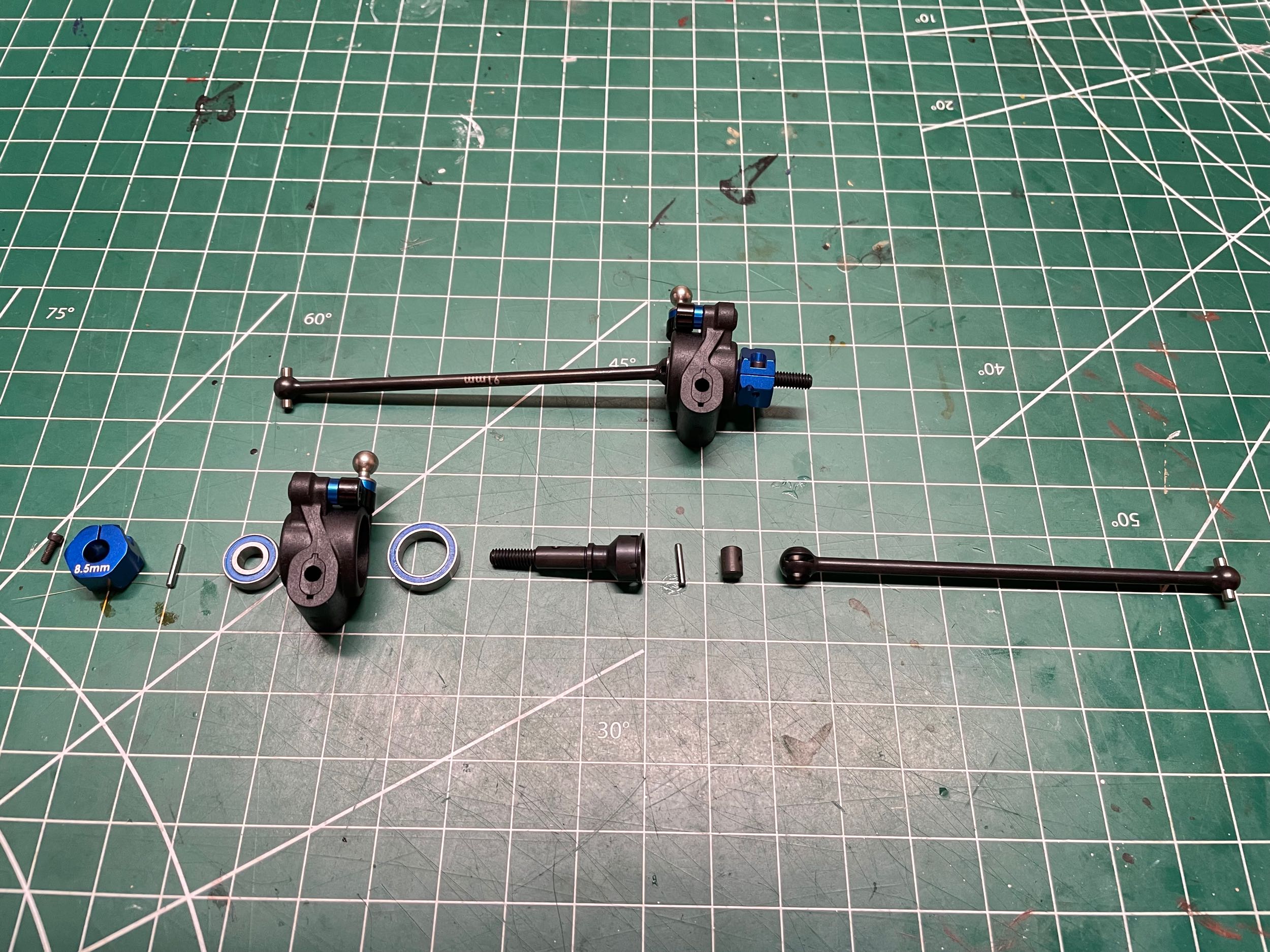
direction. Any of these could be altered. The axles have a
CVA style universal on the inboard side and a dogbone end on the
outboard side.
When the rear hubs are attached to the lower arms,
they are installed with a spacer on either side. Moving both
spacers to a single side would either slightly increase or decrease the
wheelbase. The hinge pin is retained with a tiny 2mm screw.
The rear hexes are aluminum clamping type.
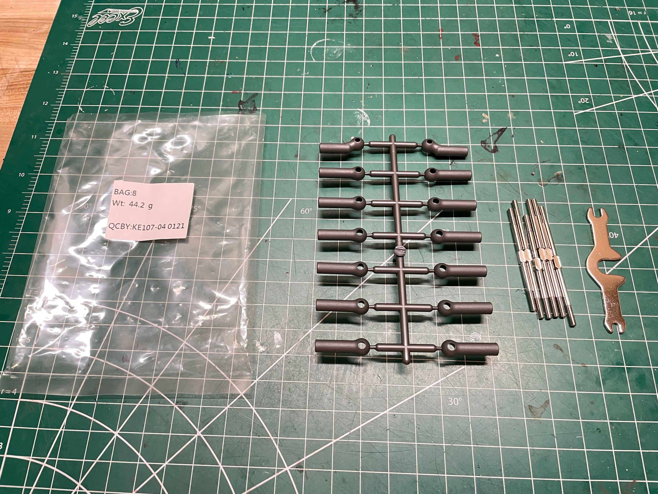
Bag 8 contains six titanium turnbuckles and twelve plastic rod
ends. These comprise the four suspension camber links and the two
steering links. Since turnbuckles use reverse threads at one end,
rotation of the rod in a single direction lengthens or shortens both
ends at one allowing easy adjustment (if you have a dedicated turnbuckle
wrench). Now the suspension operates properly as a 4-bar
linkage. Since the upper and lower arms are not exactly the same
length, the camber changes as a function of suspension travel.
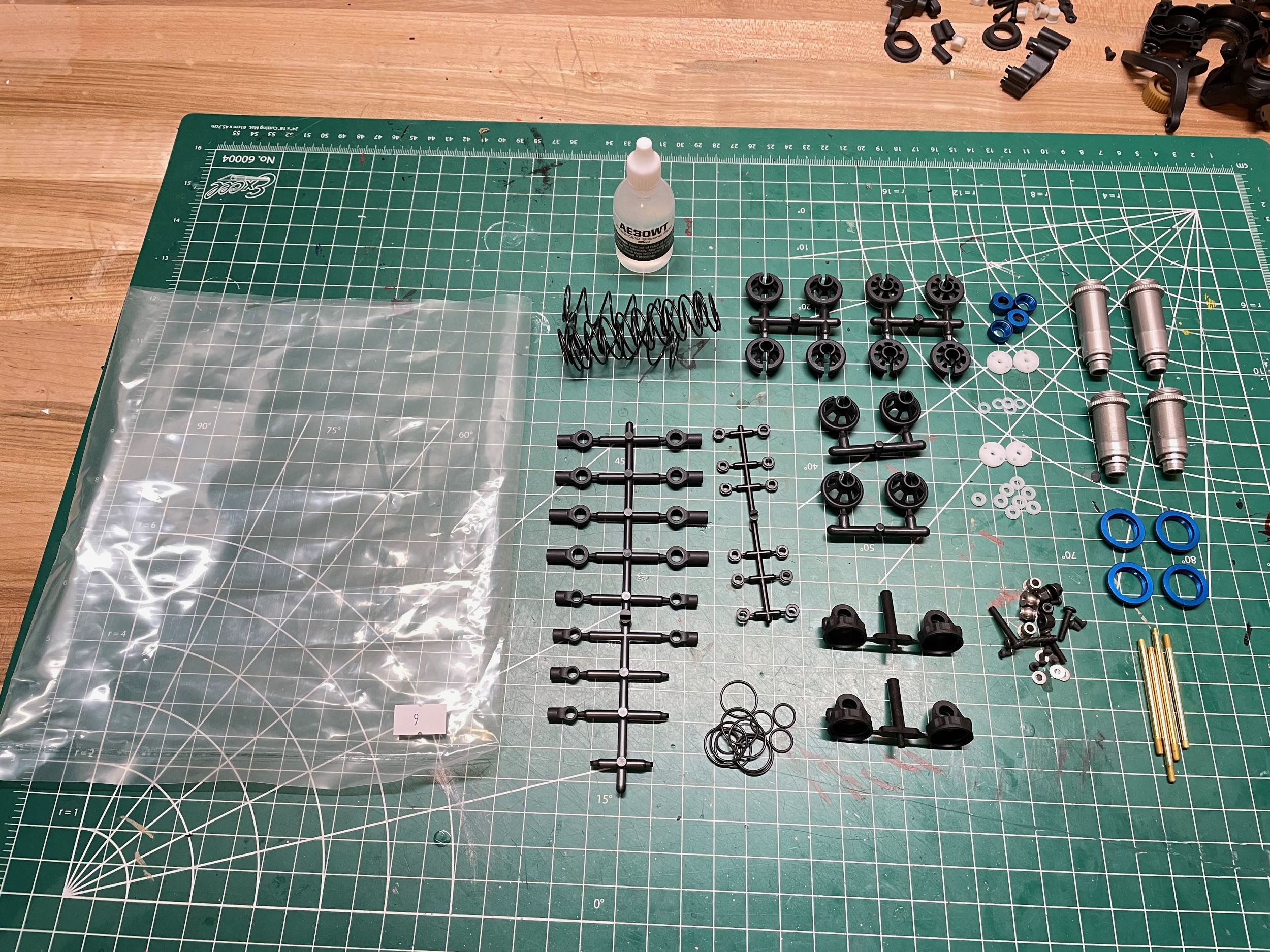
Now we get to build the beautiful shocks. The parts are contained
in Bag 9 and shown above. There are a lot of parts that go into
building these.
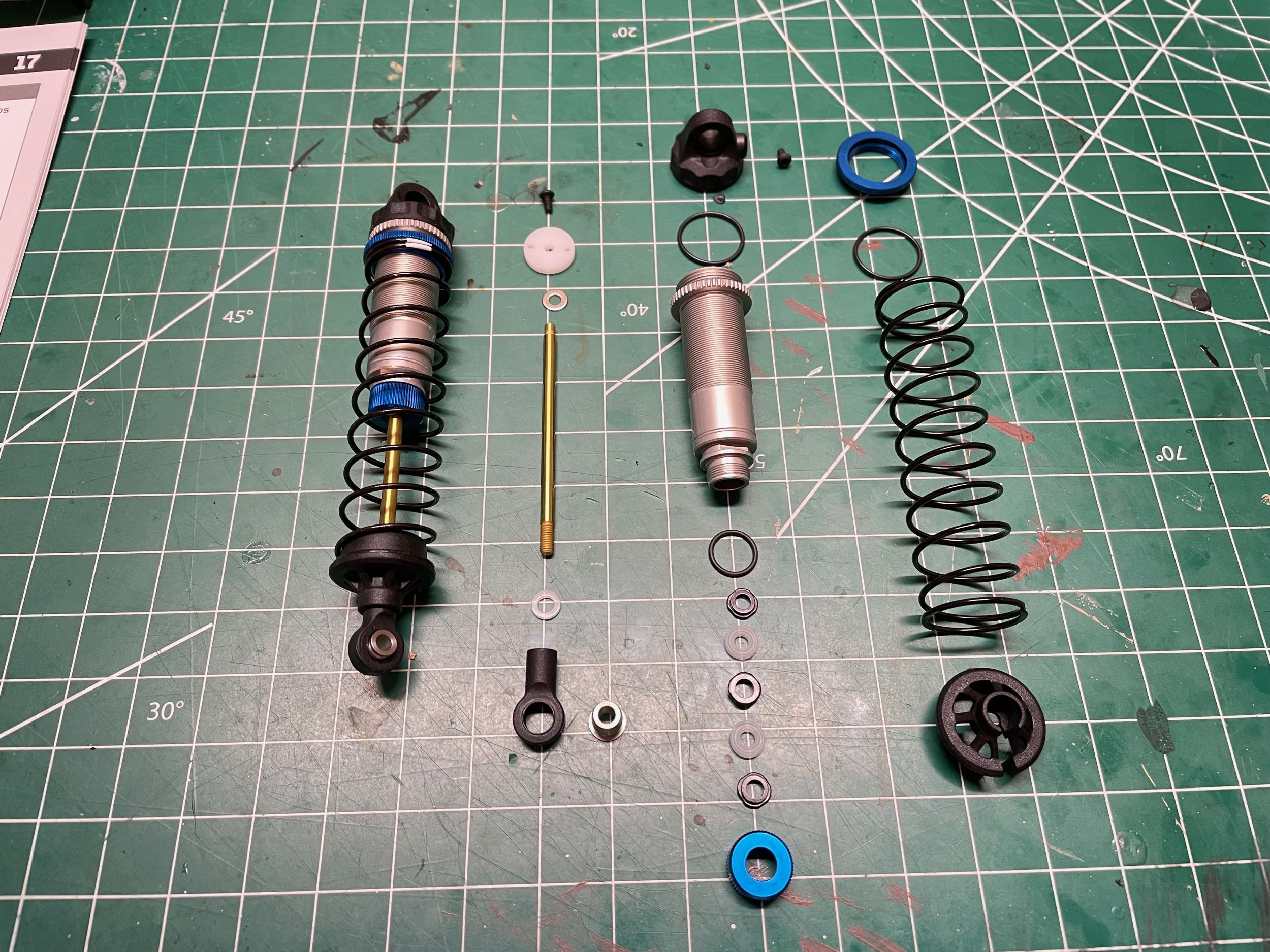
The rods are titanium nitride coated and the pistons are Delrin with two
1.6mm holes in the front and 1.7nn holes in the rear. The
aluminum
cylinders have a 12mm bore for both front and rear, though rear have a
longer stroke. Each shock has two dynamic seals and two rod
guides. All four shocks use 30wt silicone oil out of the
box. The shocks do not have a volume compensation bladder; instead
they use a
bleed screw to set the fluid level when compressed. When extended
there is a void, making these emulsion type shocks. The springs
have a substantially different rate: 4.45 lbs/in in the front and 2.40
lbs/in in the rear. Many multiple variations of spring rate (3.75 - 4.45
lbs/in front, 2.2 - 2.7 lbs.in rear), rod end length (standard to
+2mm), fluid viscosity (10 - 70 wt), and spring cup height (0, 5, 9mm)
are available as well as completely different larger 13mm bore
shocks. A completed shock is compared with an exploded view at
left. At right they've all been installed, completing the
suspension.
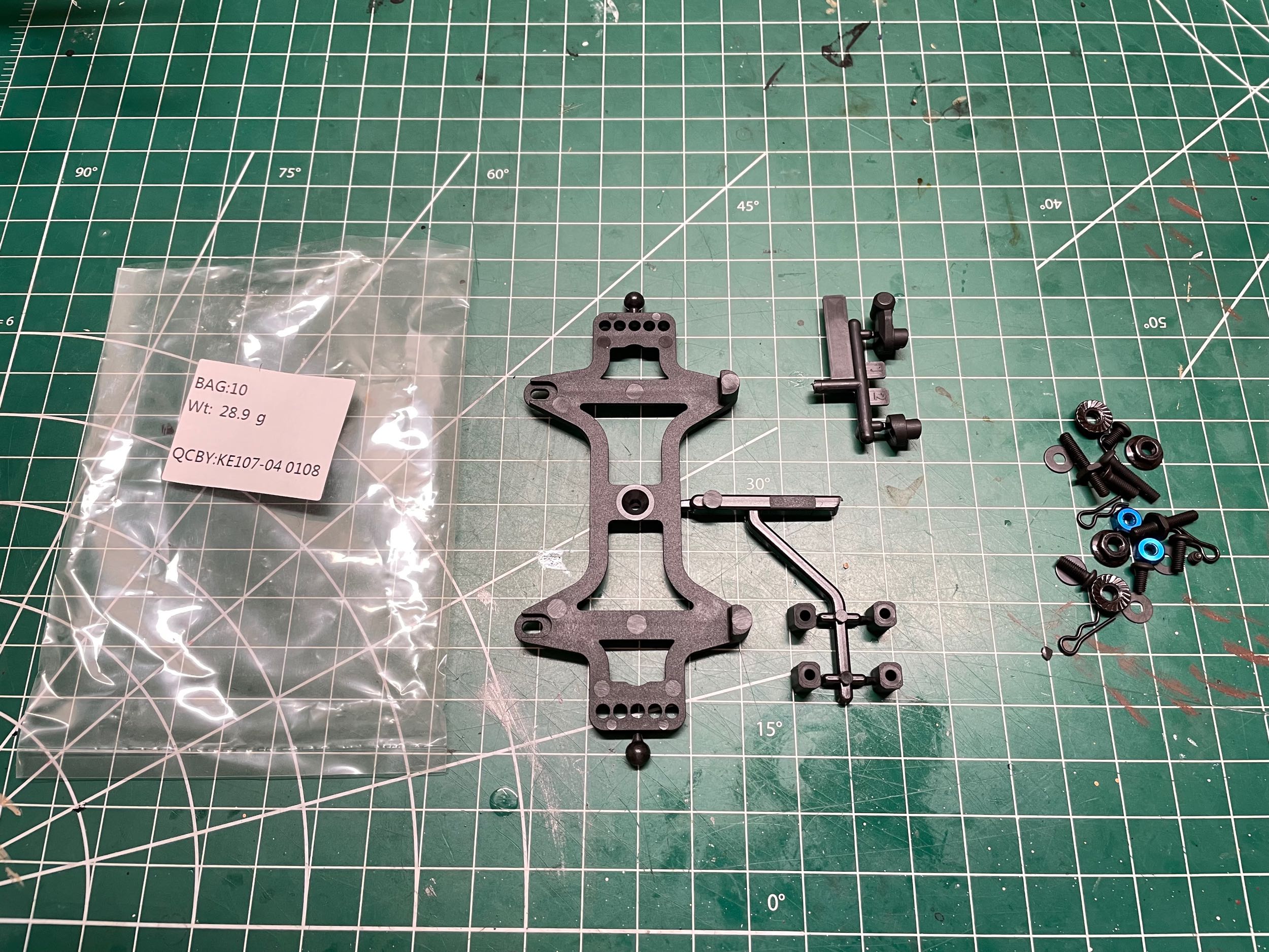
Bag 10 finishes the model with the parts for the battery strap.
This model uses a shorty hard pack (as opposed to the rare square pack
used on the 5M) held down by a rigid strap with two thumbscrews.
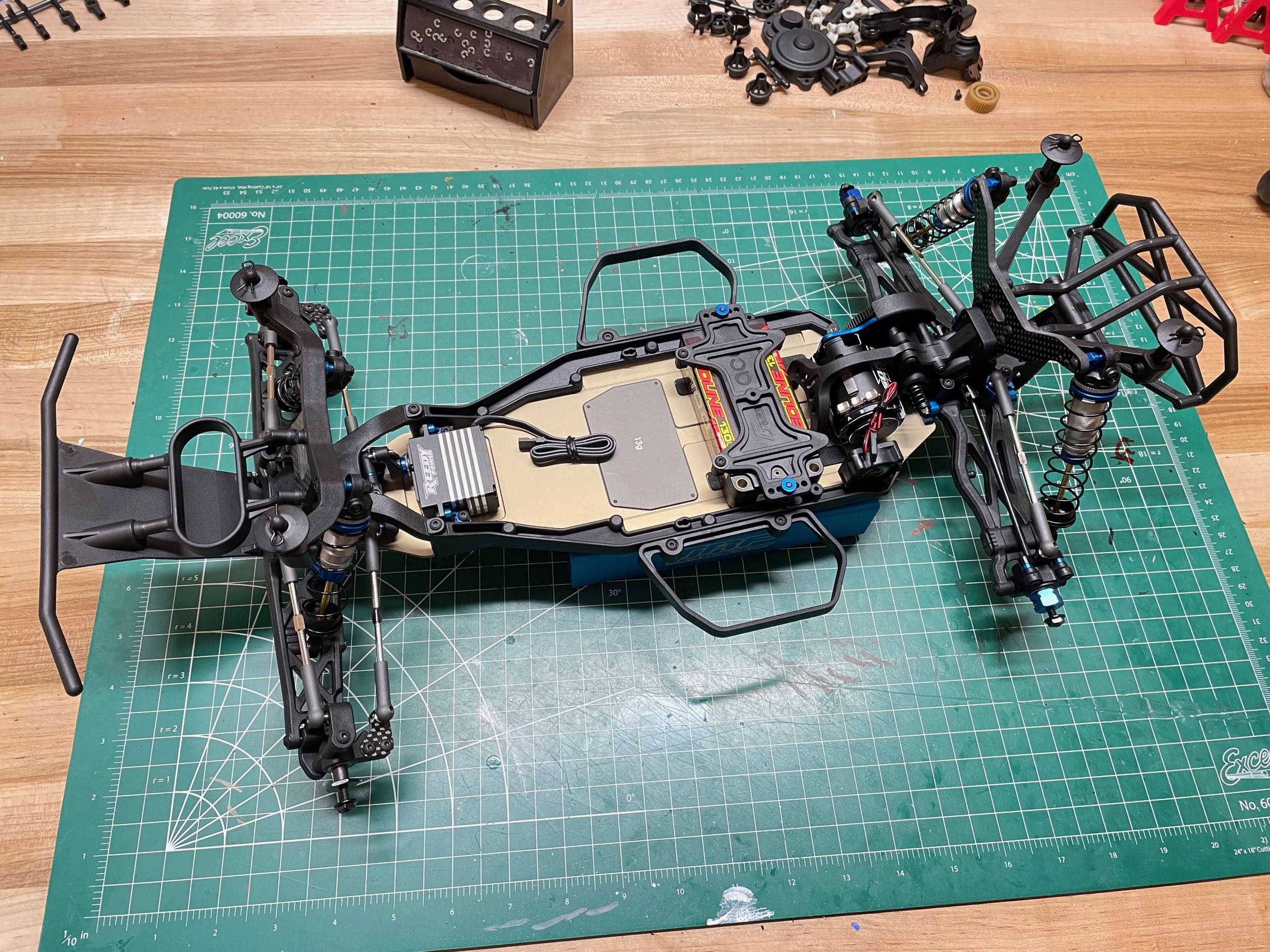
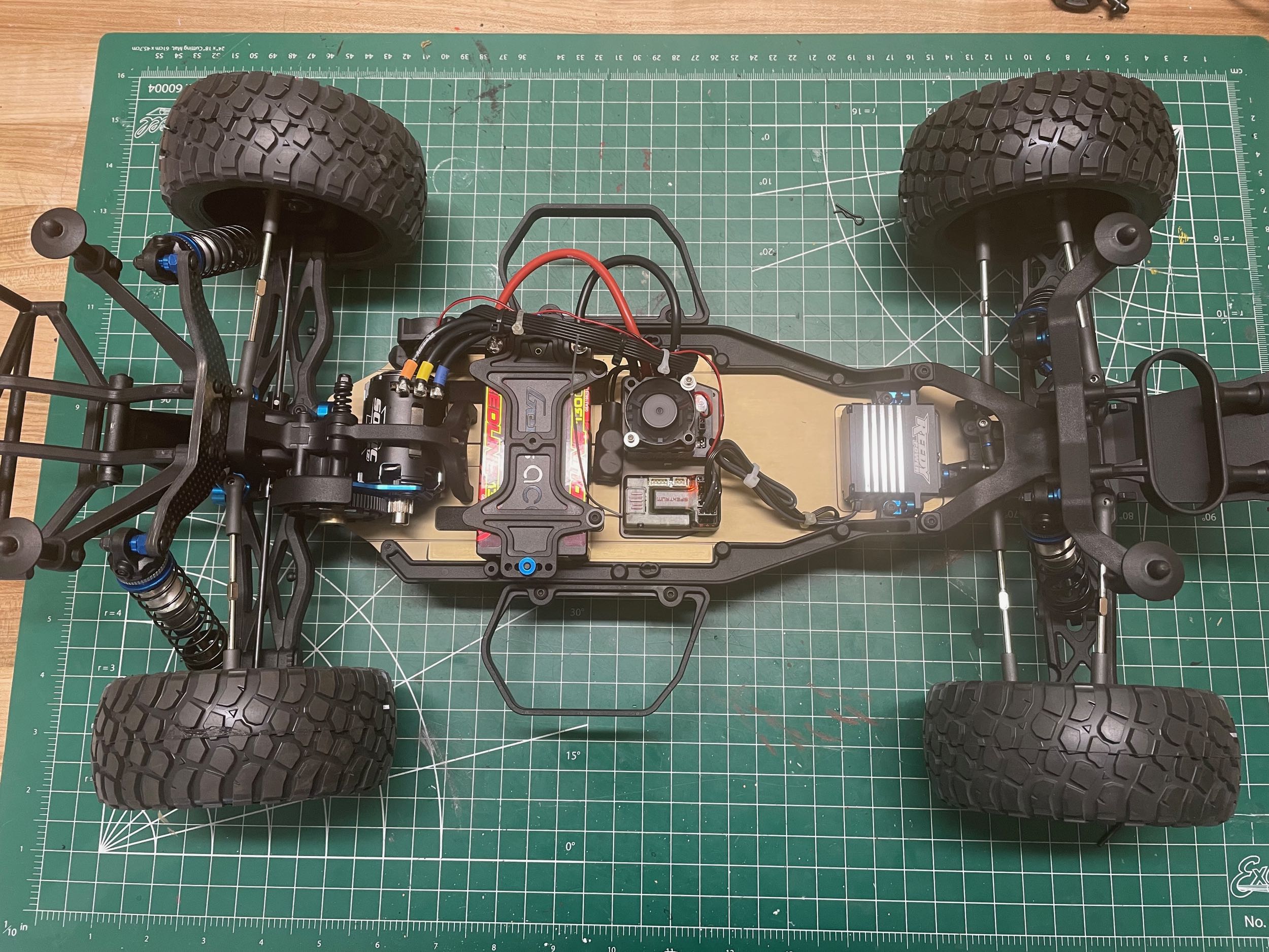
On the left I've test fit the battery and installed the motor and pinion gear. I'm using a 6.5T motor, so I matched it with an 18T pinion. The side rail also has a spot to install a cooling fan for the motor so I did that as well. On the right I've also added the electronic speed controller and the receiver. I'm using a Spektrum receiver with AVC (Active Vehicle Control) to keep things stable and compensate for my driving skills. There is a second fan on the ESC. Finally, I've added a set of Proline KR2 tires.