Tamiya Sand Rover Project
Page 1: Assembly
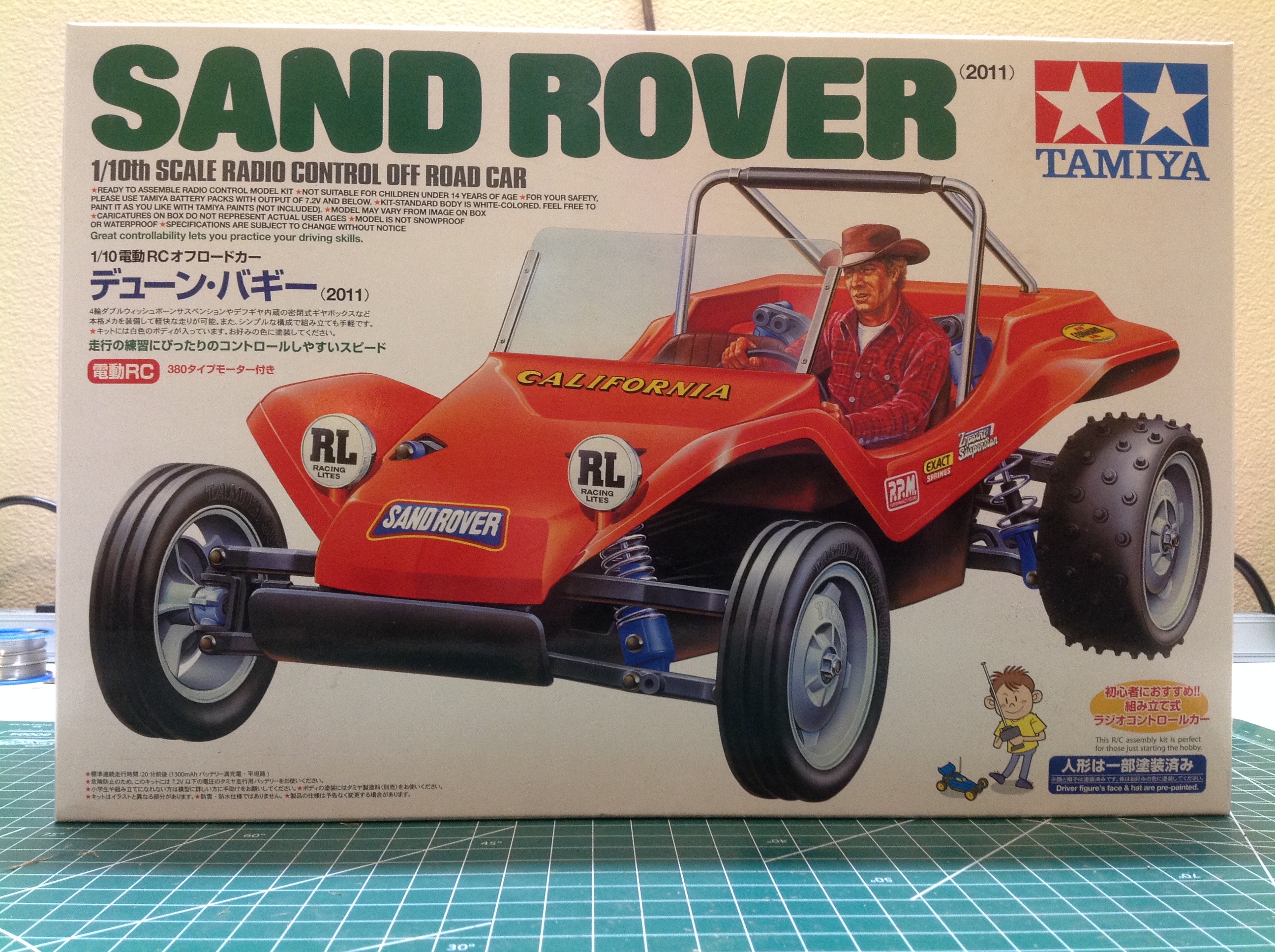
The art on the Sand Rover box mimics that of the original box, but the
changes to the track width, shock locations, and stickers have been
incorporated so it is clearly the re-released version. The picture
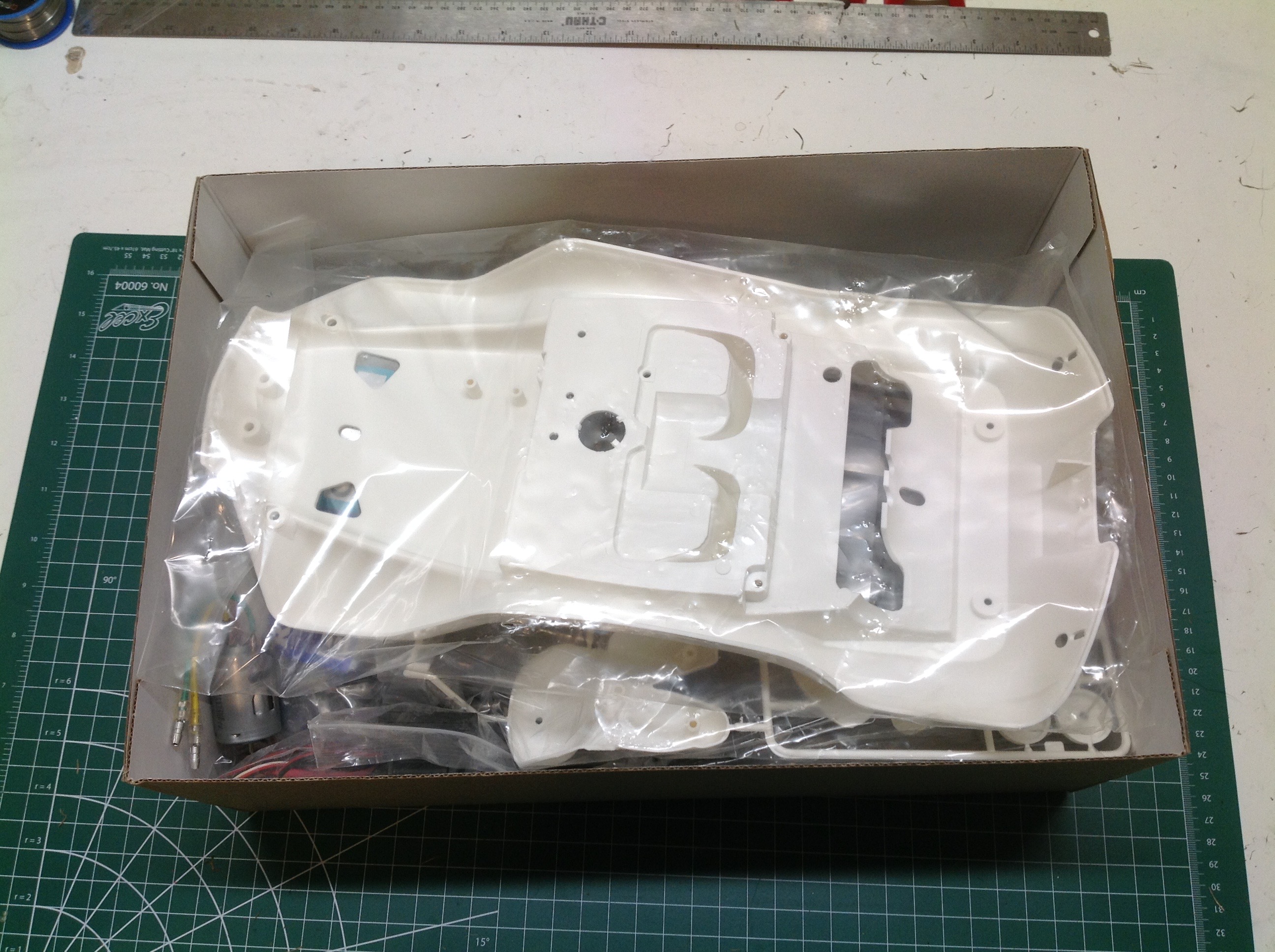
on the right shows the contents of the box which are dominated by the
hard shell body.
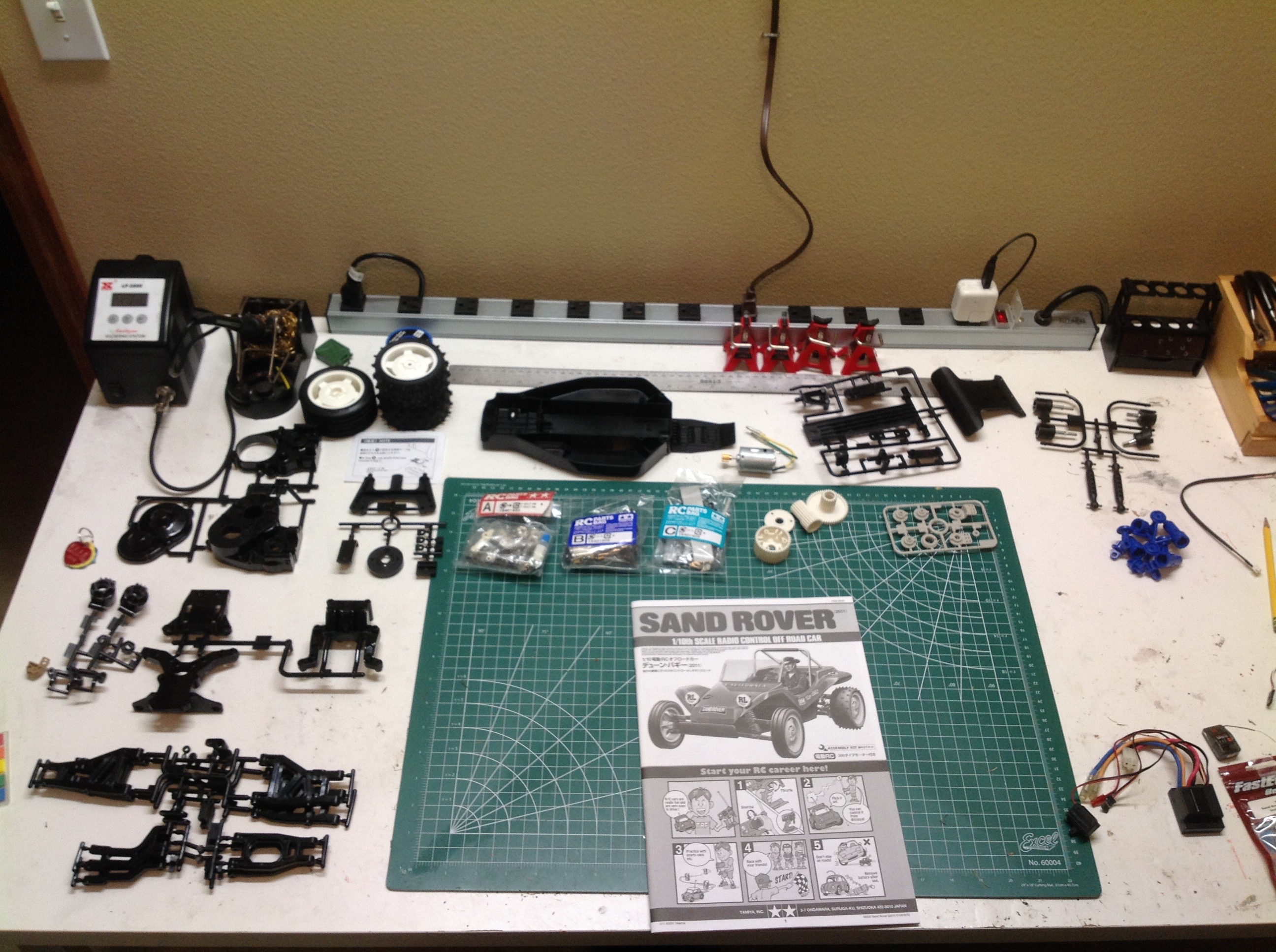
This is a pretty simple model as you can see by the relatively small
number of parts. One oddity that is not so obvious from the
picture is that this instruction manual is a different size than all the
others. It is larger for some reason and therefore does not fit
in my file cabinet.
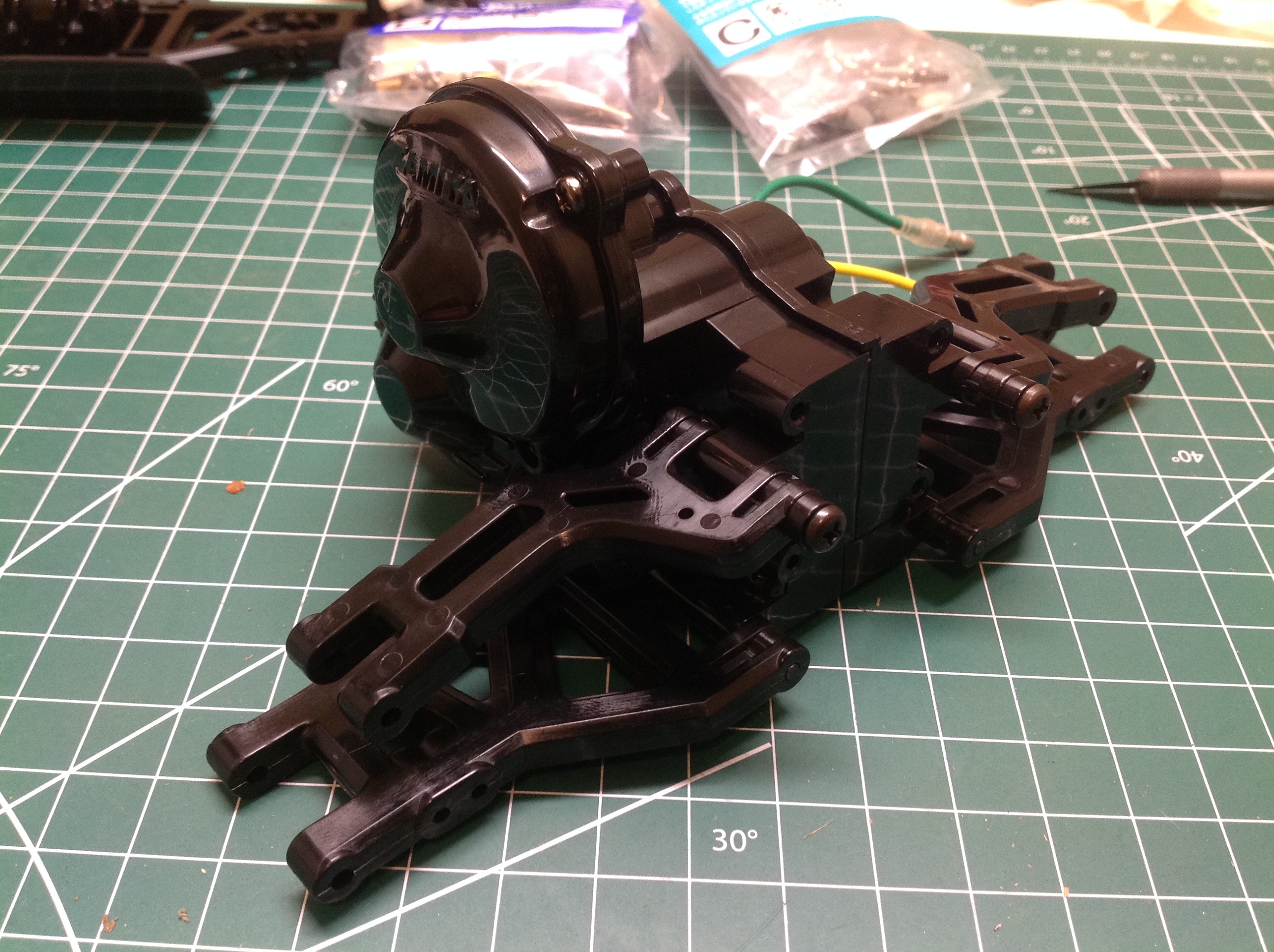
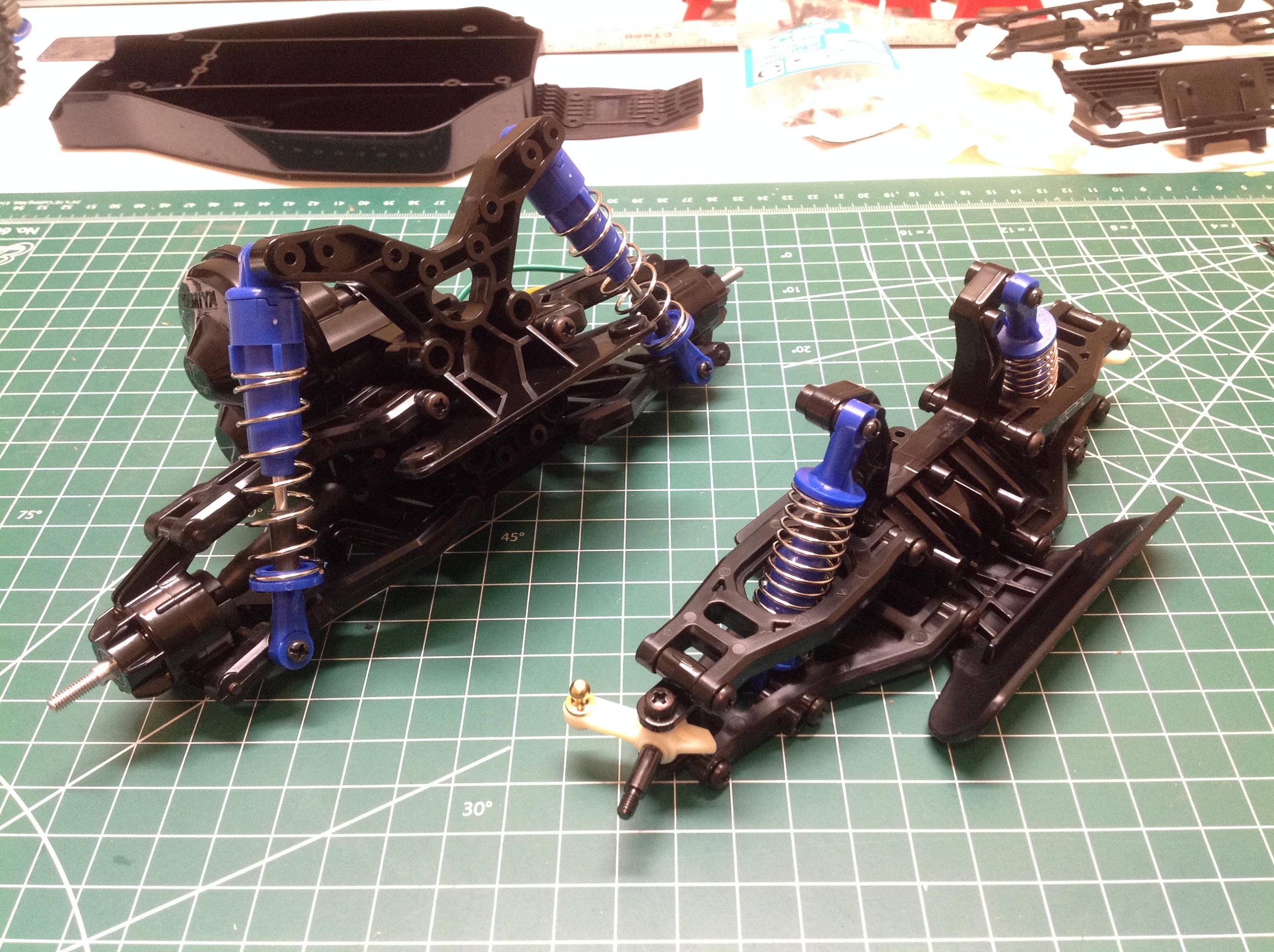
The chassis build starts with the front suspension module which can be
completely built apart from the chassis tub. Both the upper and
lower suspension arms are sturdy wishbones and the shock tower is
tall. The front bumper is integrated into the suspension module.
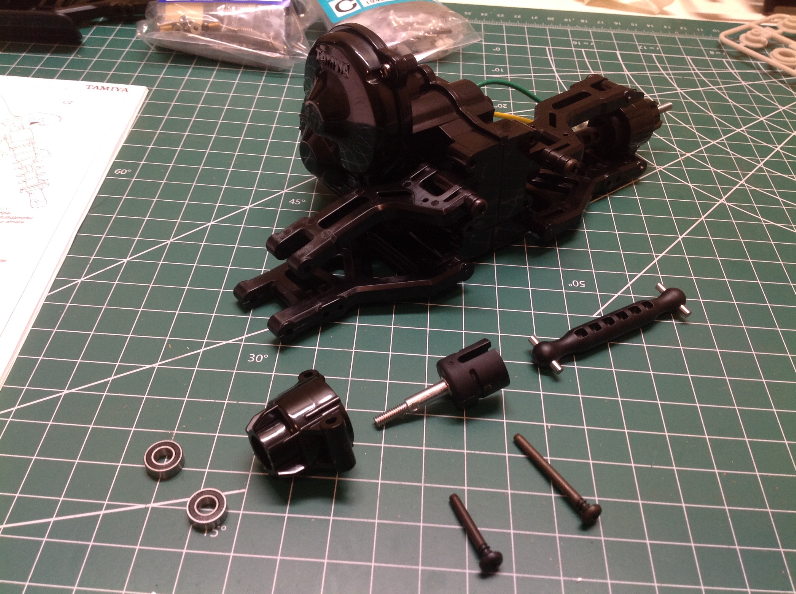
The open rear differential sits inside a very large housing as
shown. The outer spur gear mates with a much smaller counter
gear. The kit did not come with ball bearings, but I added them
during the initial build as usual.
Just like the original, this kit comes with only a tiny 380 sized
motor. It can accept a 540 motor as an upgrade. The small
brass pinion is pressed onto the shaft and is not intended to be
replaced. The picture on the right shows the installed motor and
spur gear.
Once the gearbox cover is installed as shown, the drive cups can be
installed. These are interesting parts with metal shafts molded
directly into the plastic cups.
Now the upper and lower wishbone arms are attached to the rear gearbox
assembly with pivot pins. The axle is a plastic shaft with metal
pins as shown.
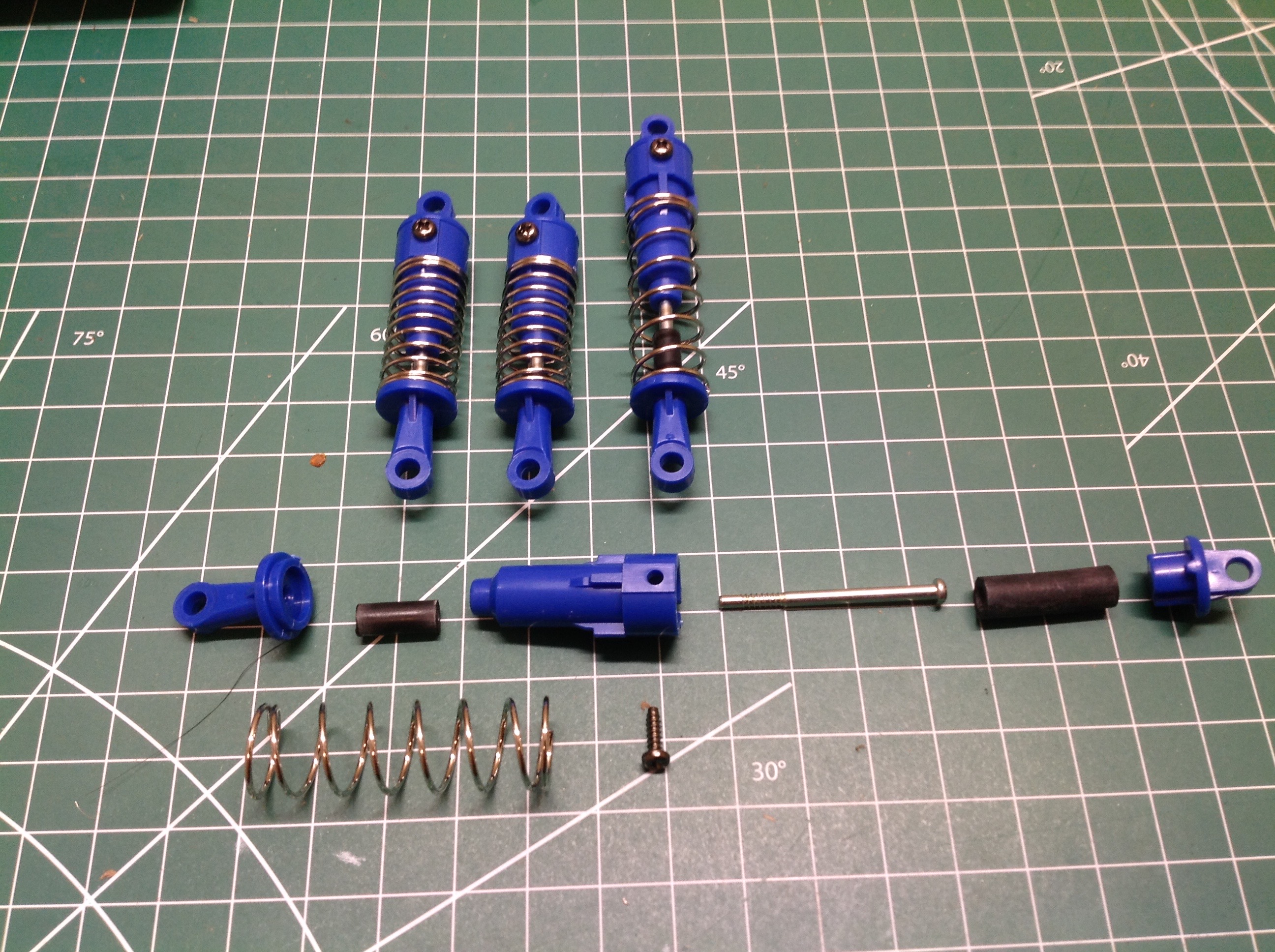
This kit comes with the dreaded friction dampers, but the included
rubber sleeve actually does a semi acceptable job of providing some
resistance to motion. Note how much longer the rear shocks are
than the front. The picture on the right shows the completed
suspension assemblies with shocks installed.
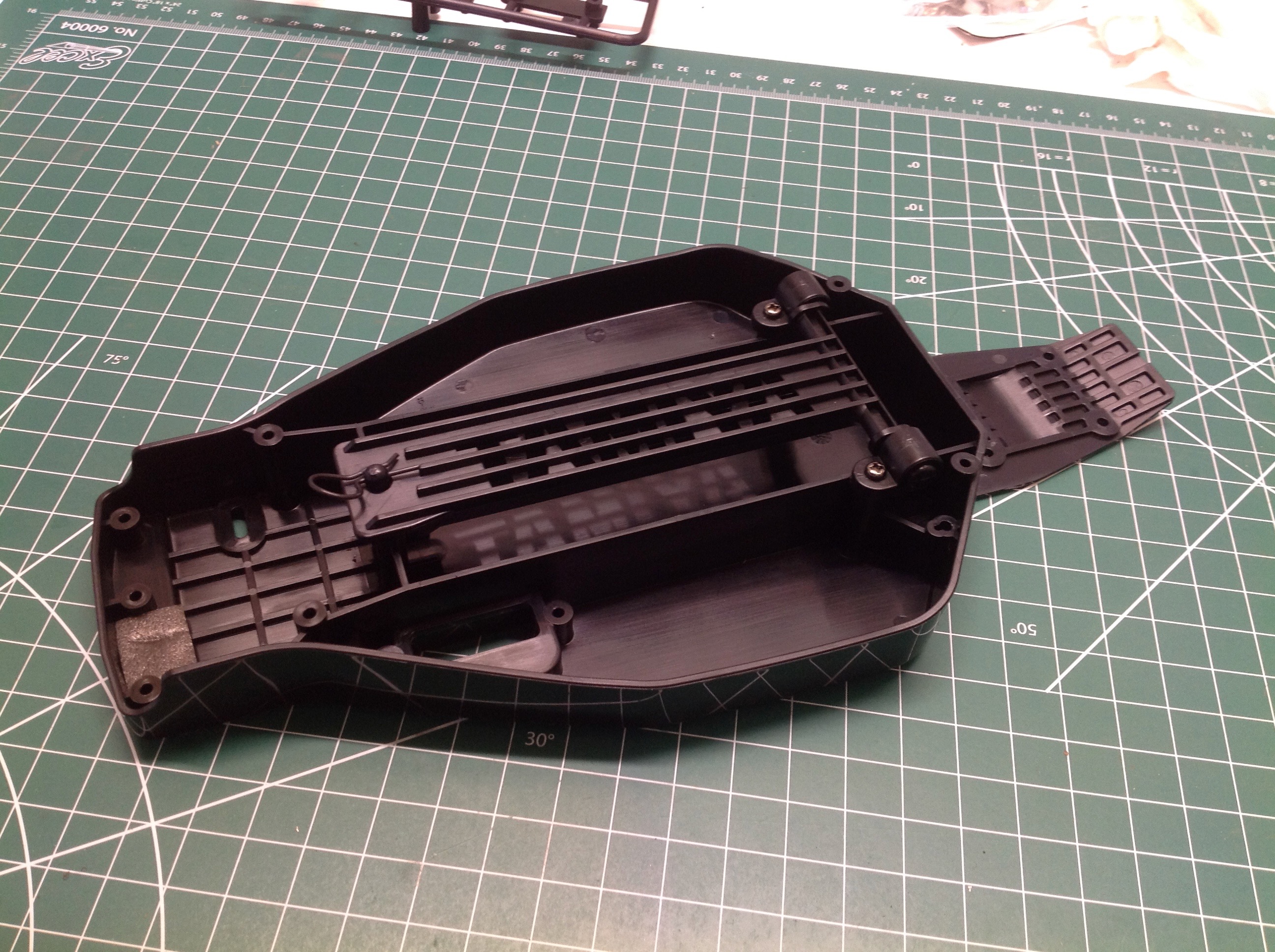
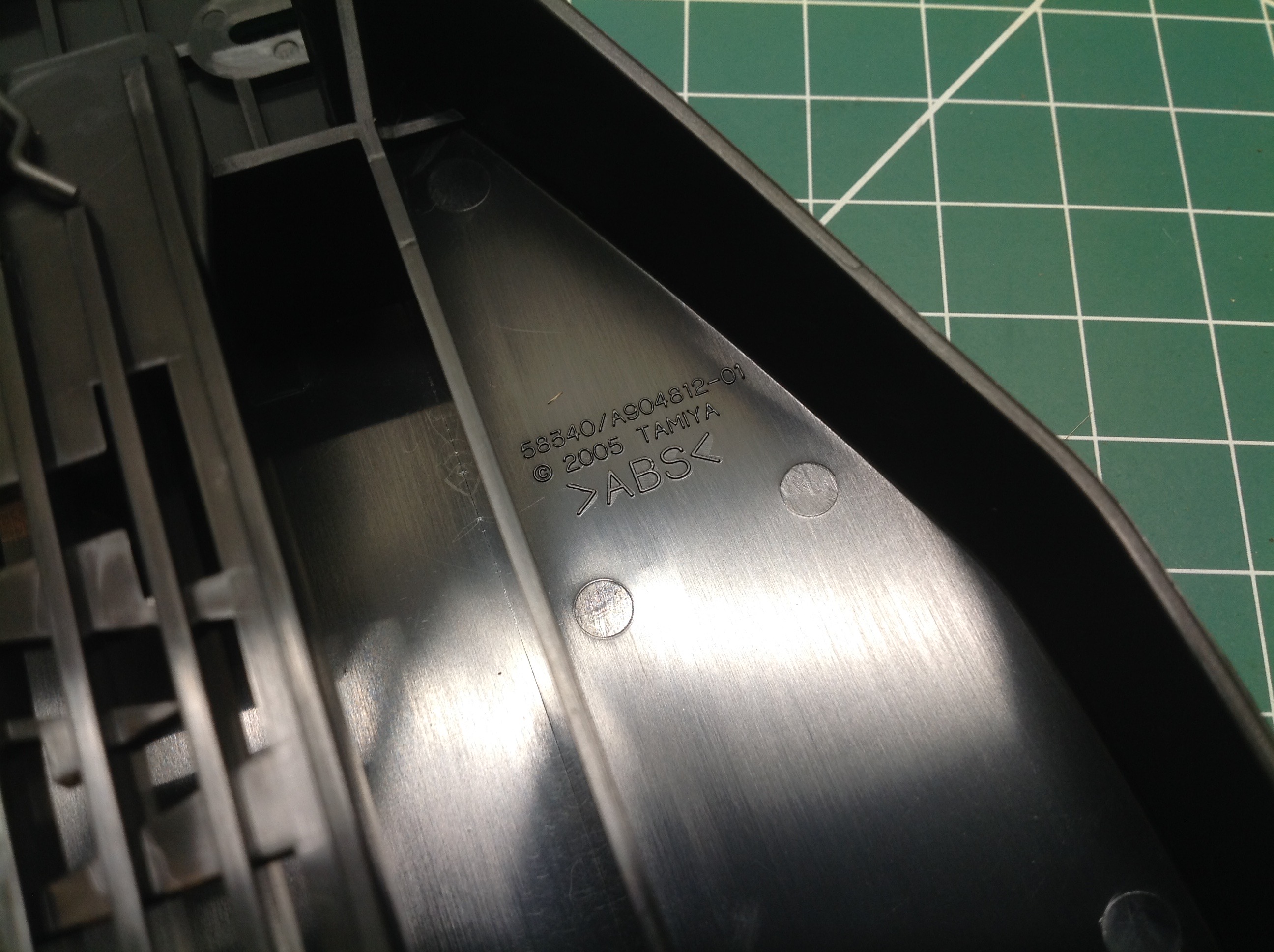
The main chassis is pretty much just a single tub part. The
battery cover sits on top and hinges at the rear. The chassis is
made from ABS (acrylonitrile butadiene styrene).
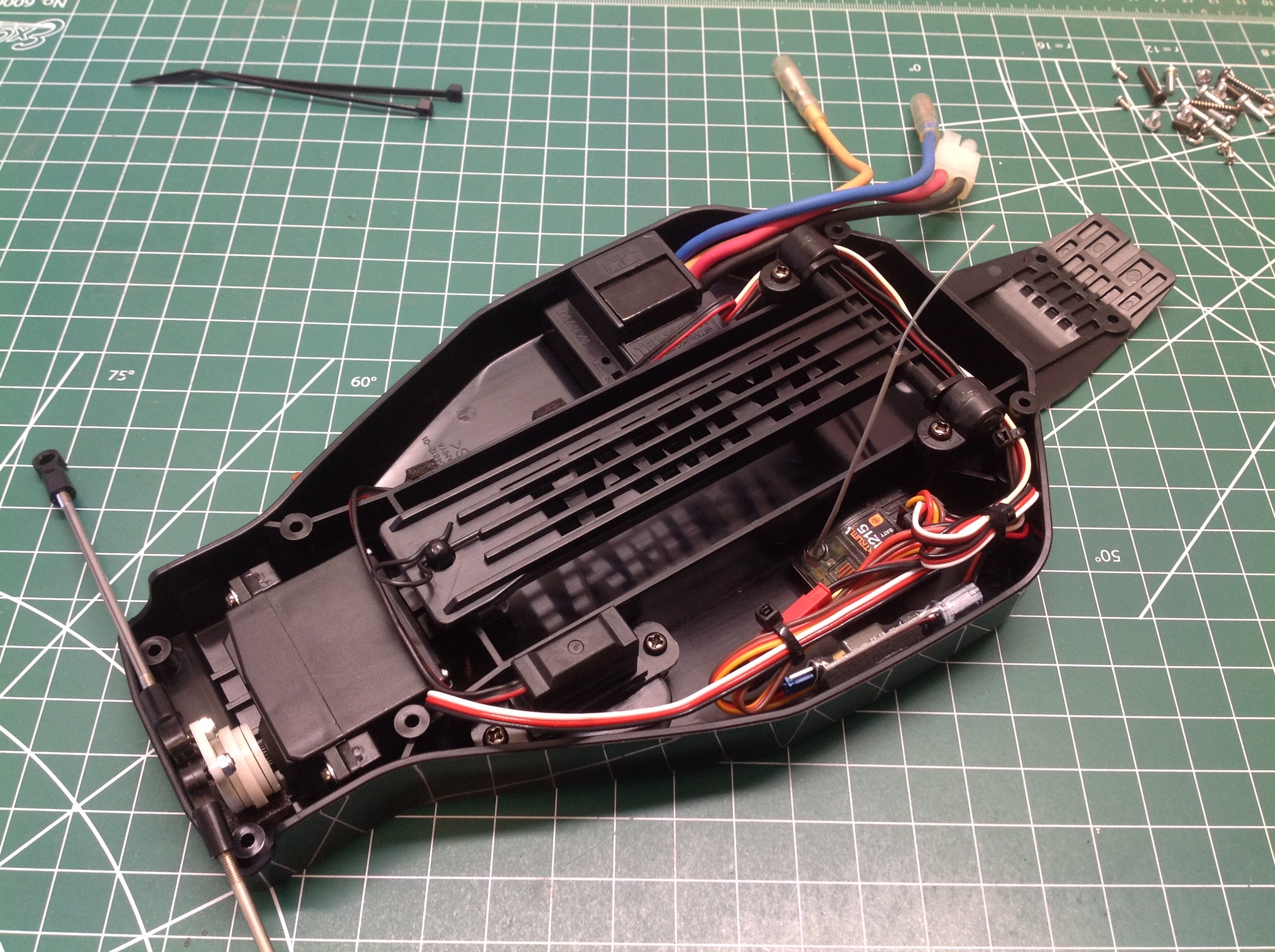
Next the electronics are installed which is pretty easy. I
happened to have an ancient TEU-101BK ESC for this model which does not
have an internal BEC so I had to add one. The steering servo
drives the steering links directly as shown. There is still plenty
of room to spare.
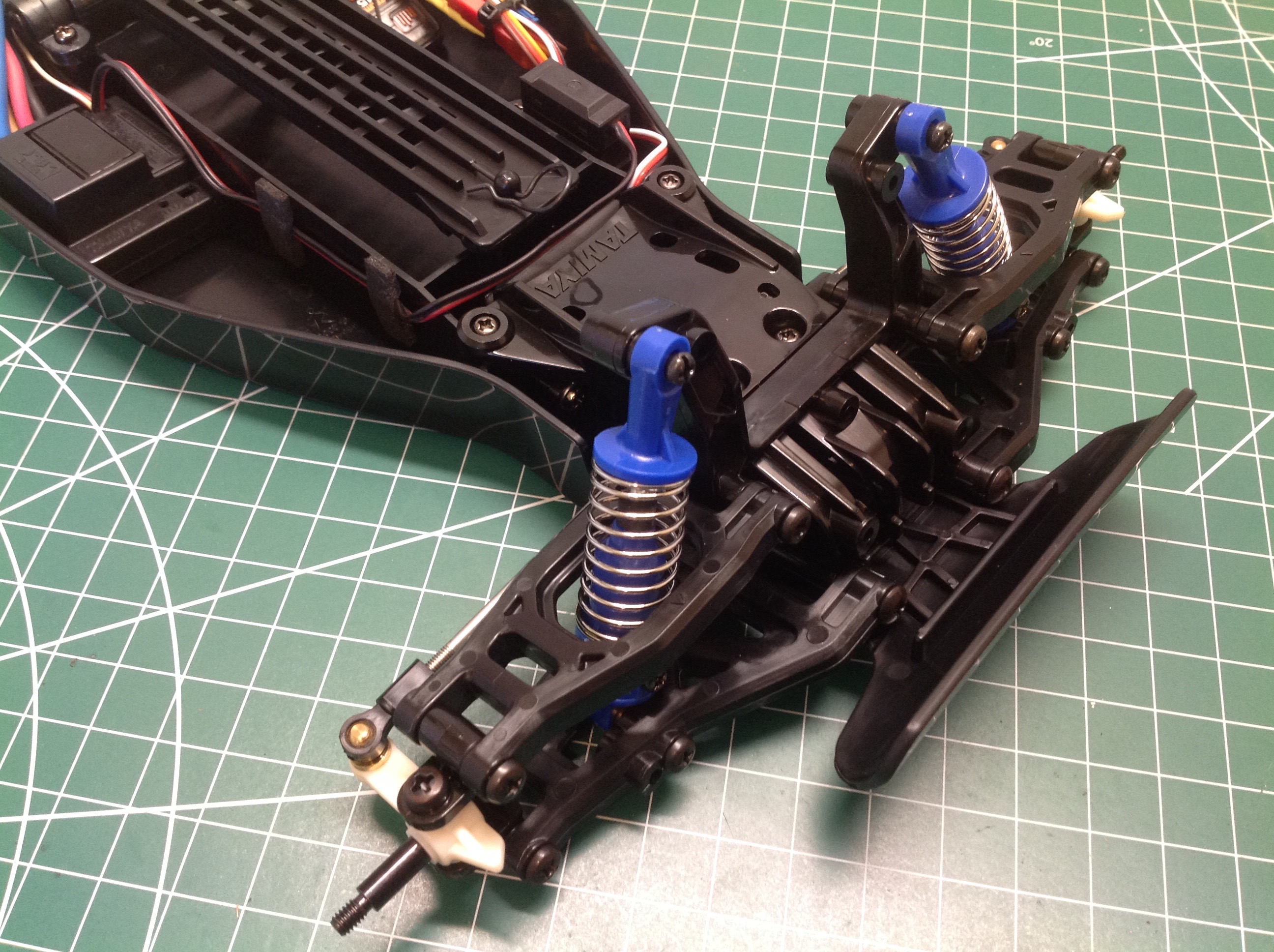
Now the front and rear suspension modules are simply screwed to the chassis tub.
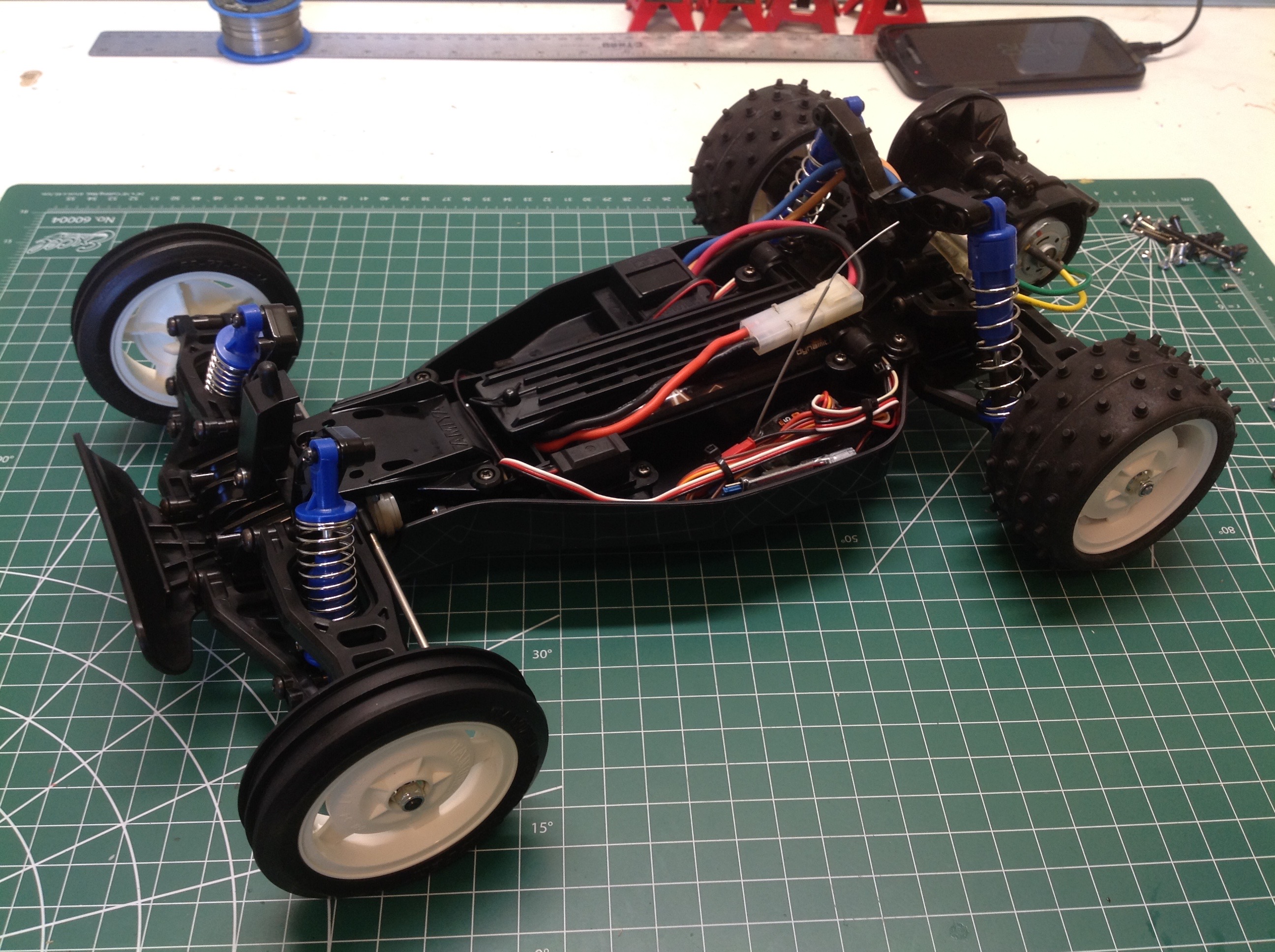
The chassis is completed by installing the wheels and tires. This is a very sturdy chassis.
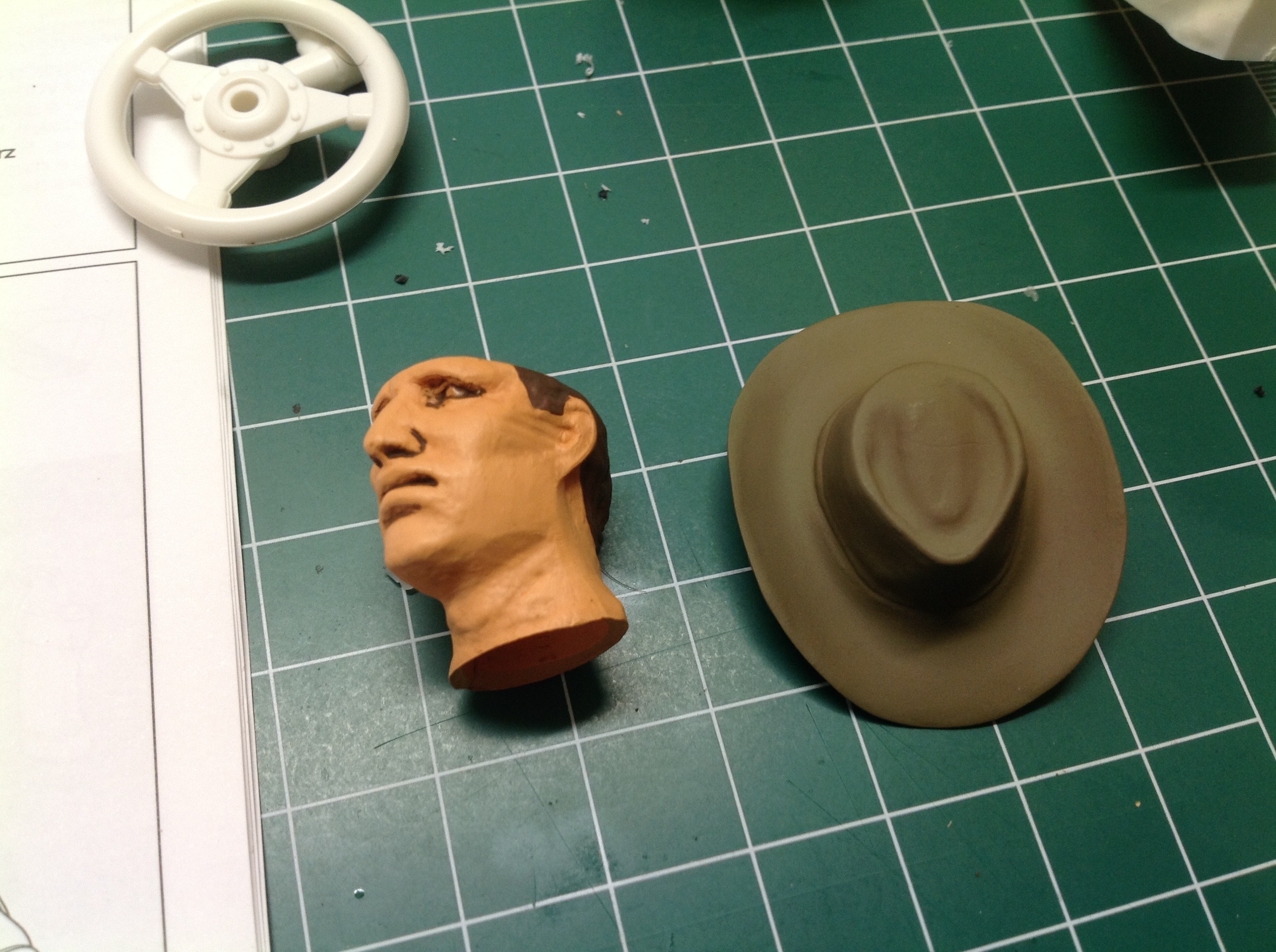
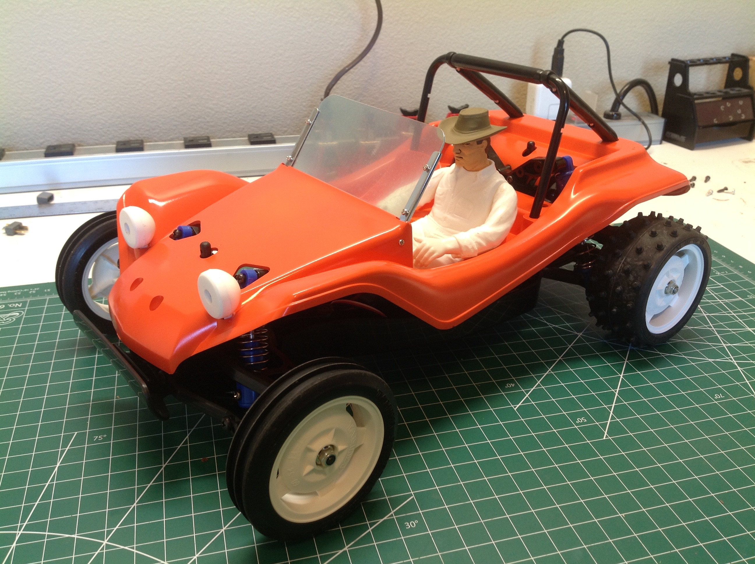
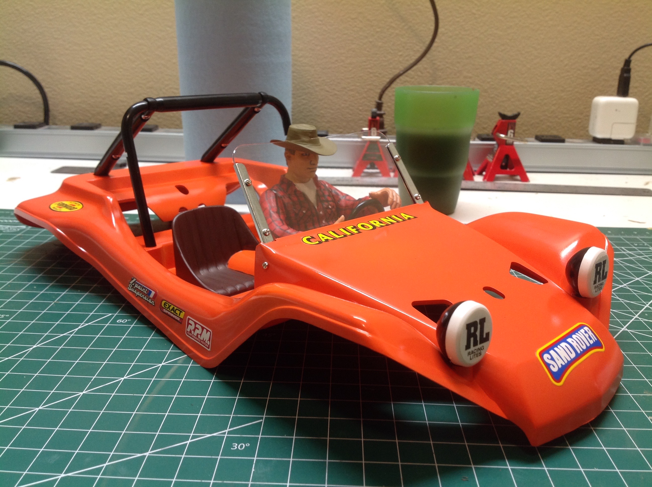
The driver's face and hat come prepainted with this kit, but nothing
else. In the picture on the right I've sprayed the body in orange
and then test fit all the other unpainted parts.
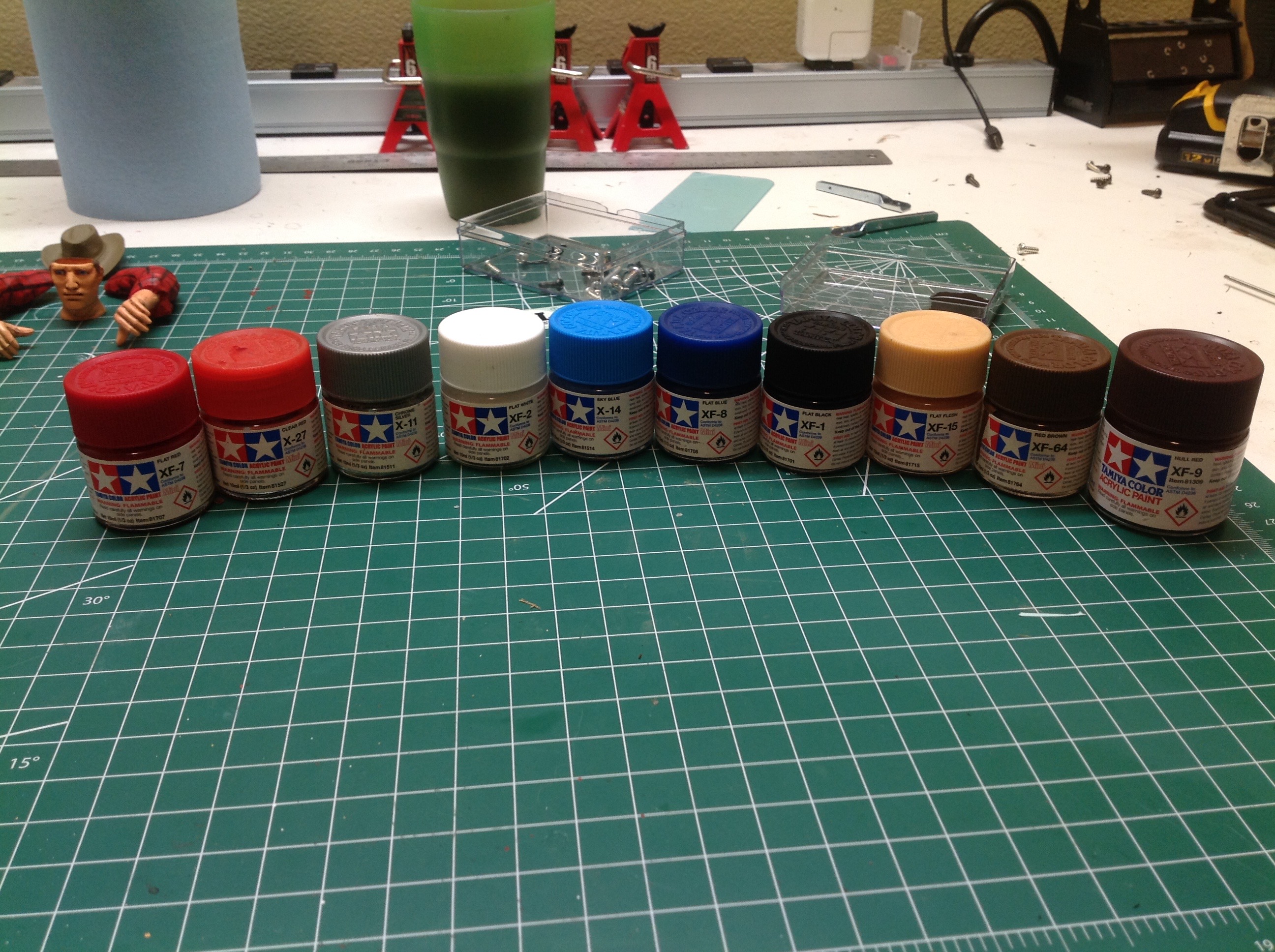
You might think that this would be a pretty easy single color paint job,
but you'd be wrong. I needed all the colors shown above, many
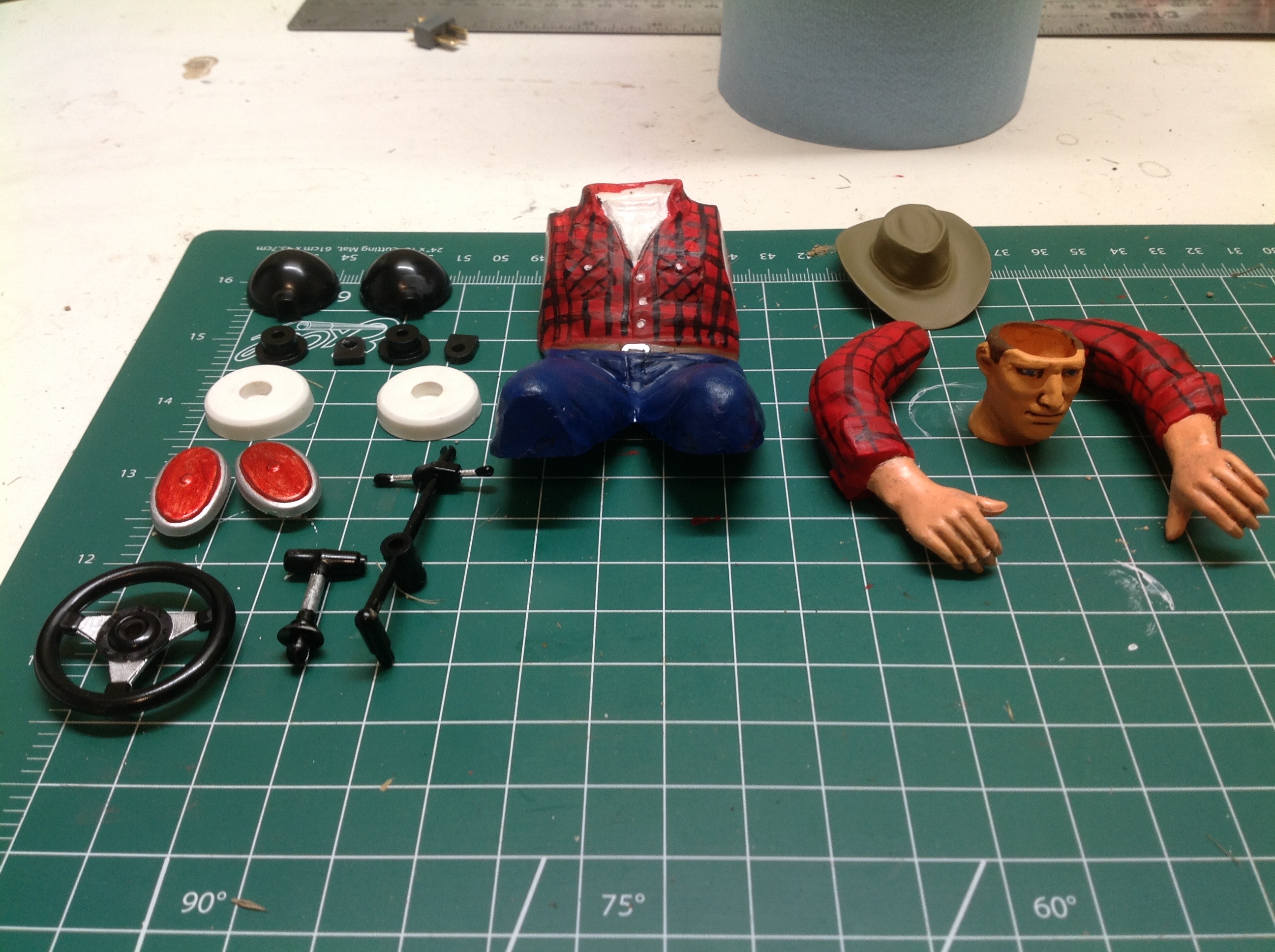
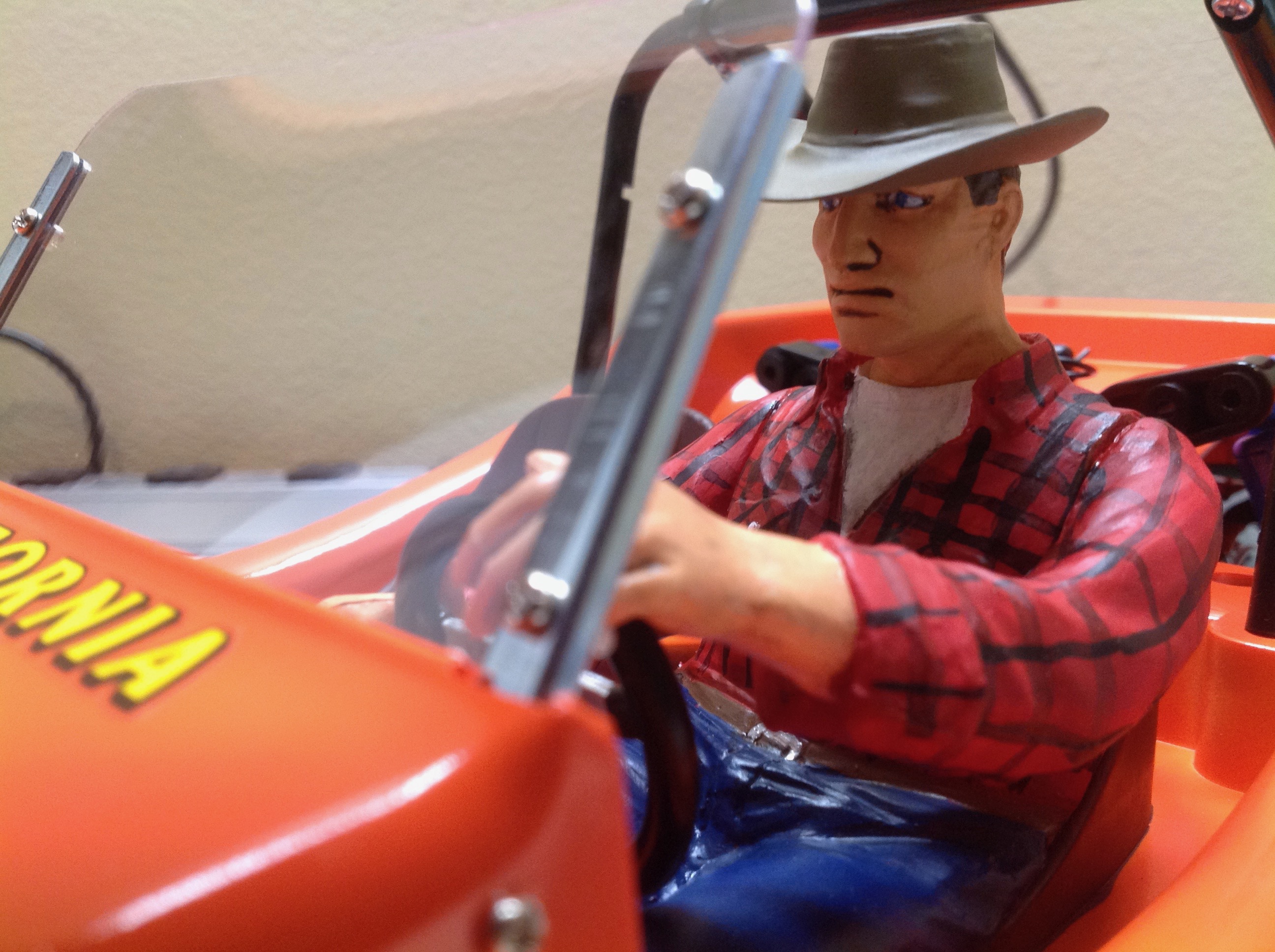
just for the driver. I decided to try painting a flannel shirt and
jeans. I also used trans red for the tail lights and aluminum for
bits of the steering wheel and levers.
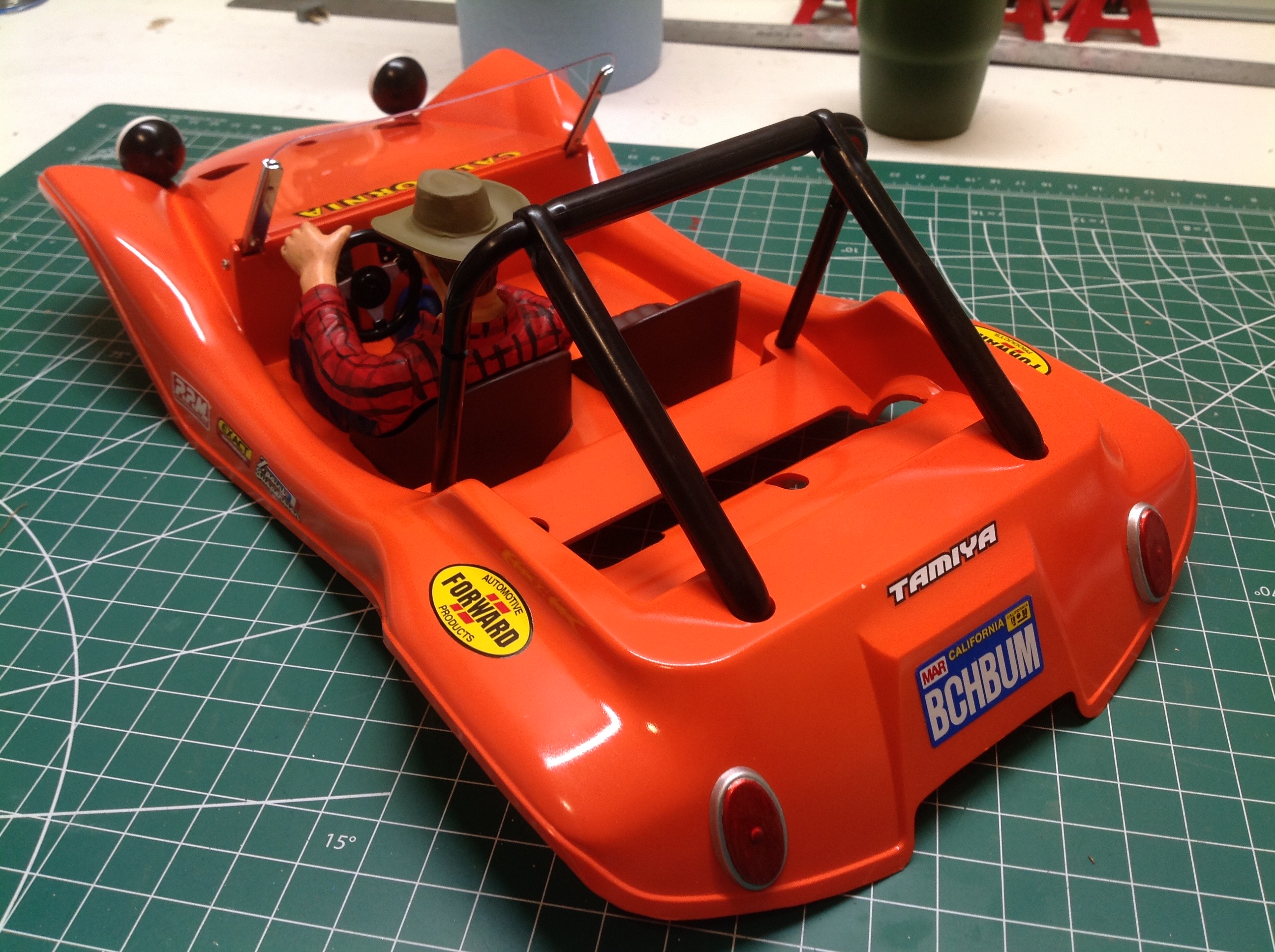
I painted the seats by hand and sprayed the roll bar and lights.
The windshield is supported by little metal brackets and itself is just a
sheet of Lexan.
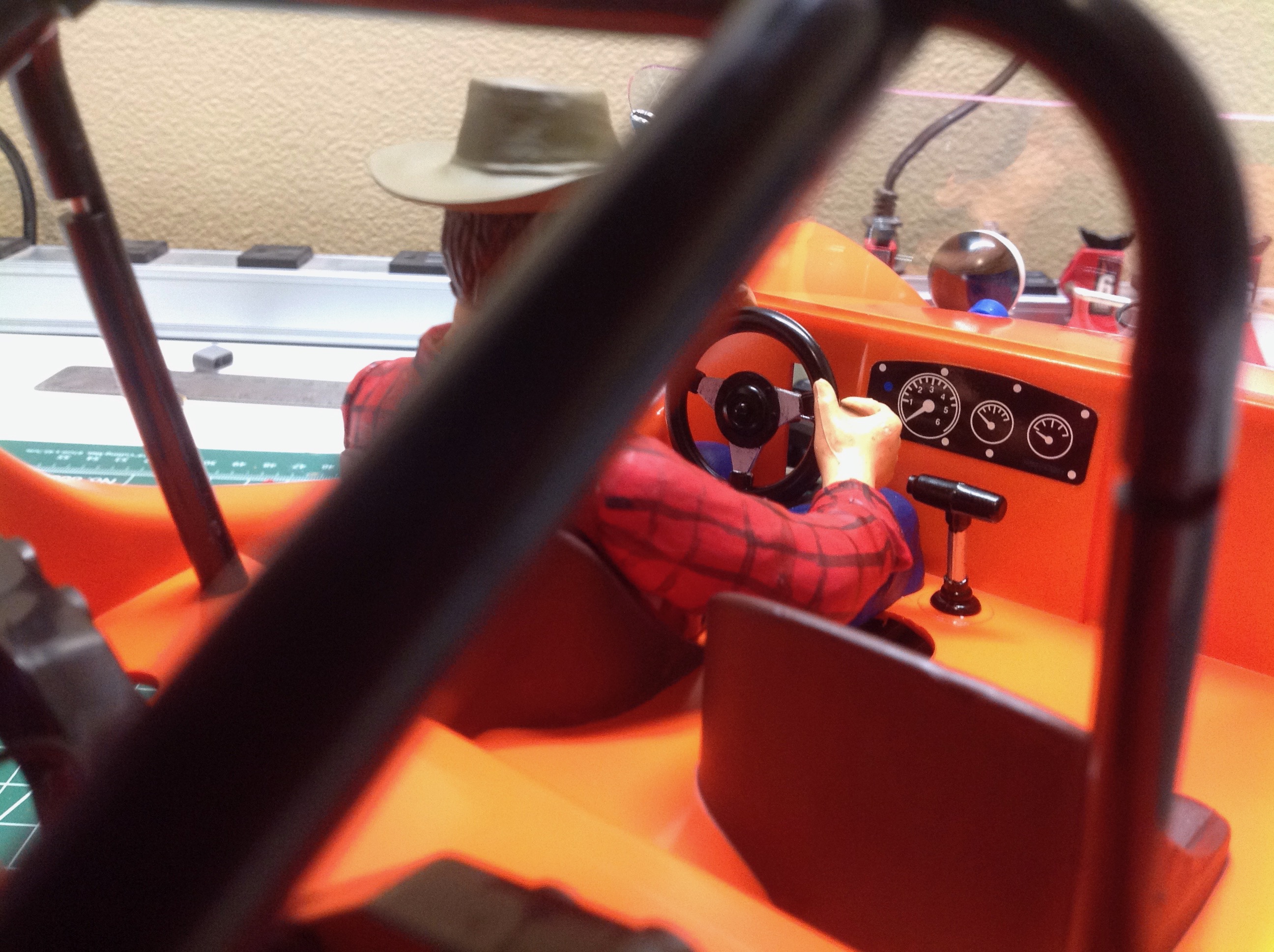
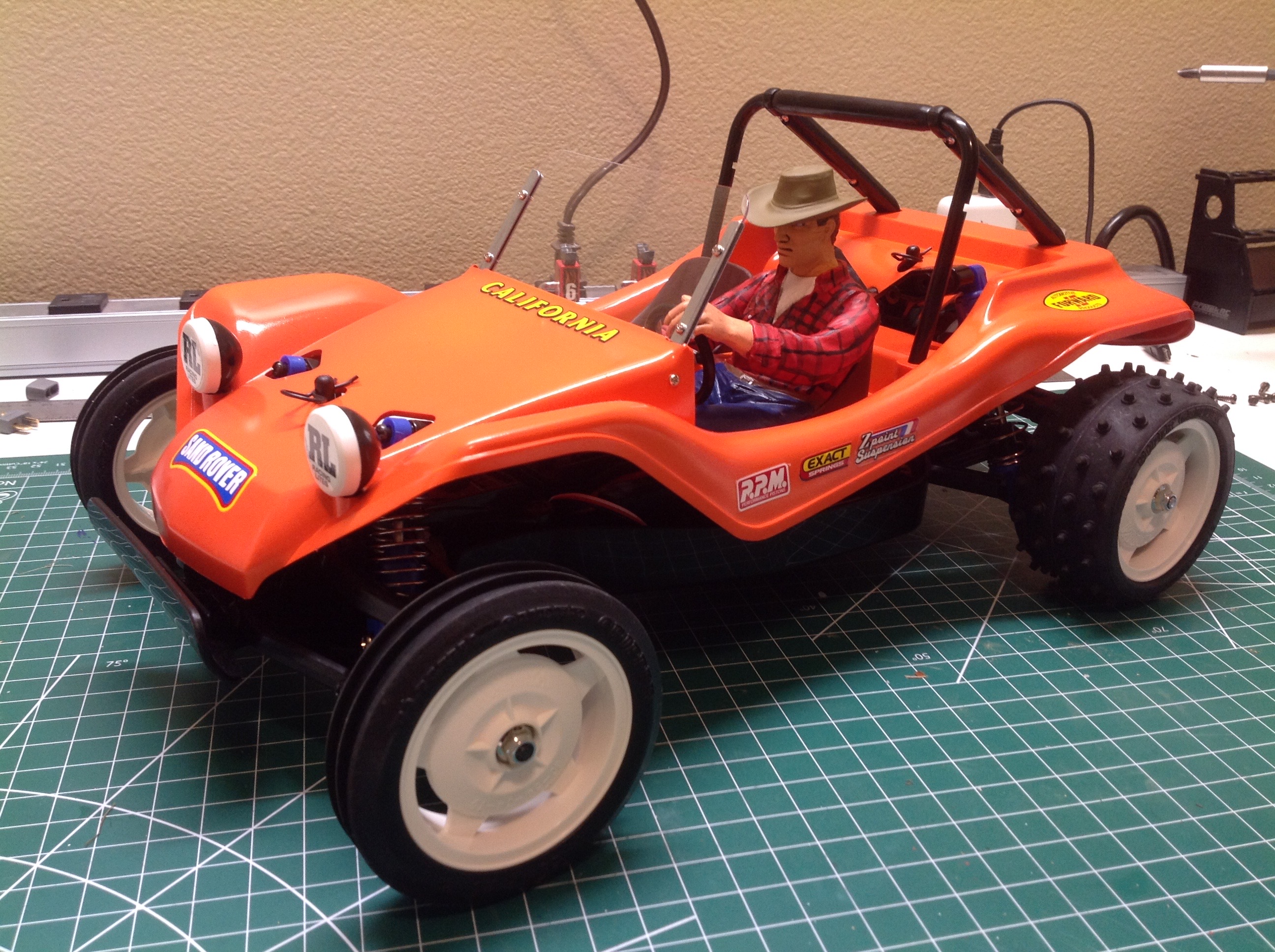
There are a few stickers for the dash as you can see on the left.
The right shows the completed driver attached to the buggy.
Et voila! I think it looks pretty good even though it is much wider than the original.
©2021 Eric Albrecht