Kyosho Scorpion Project
Page 1: Stock Assembly
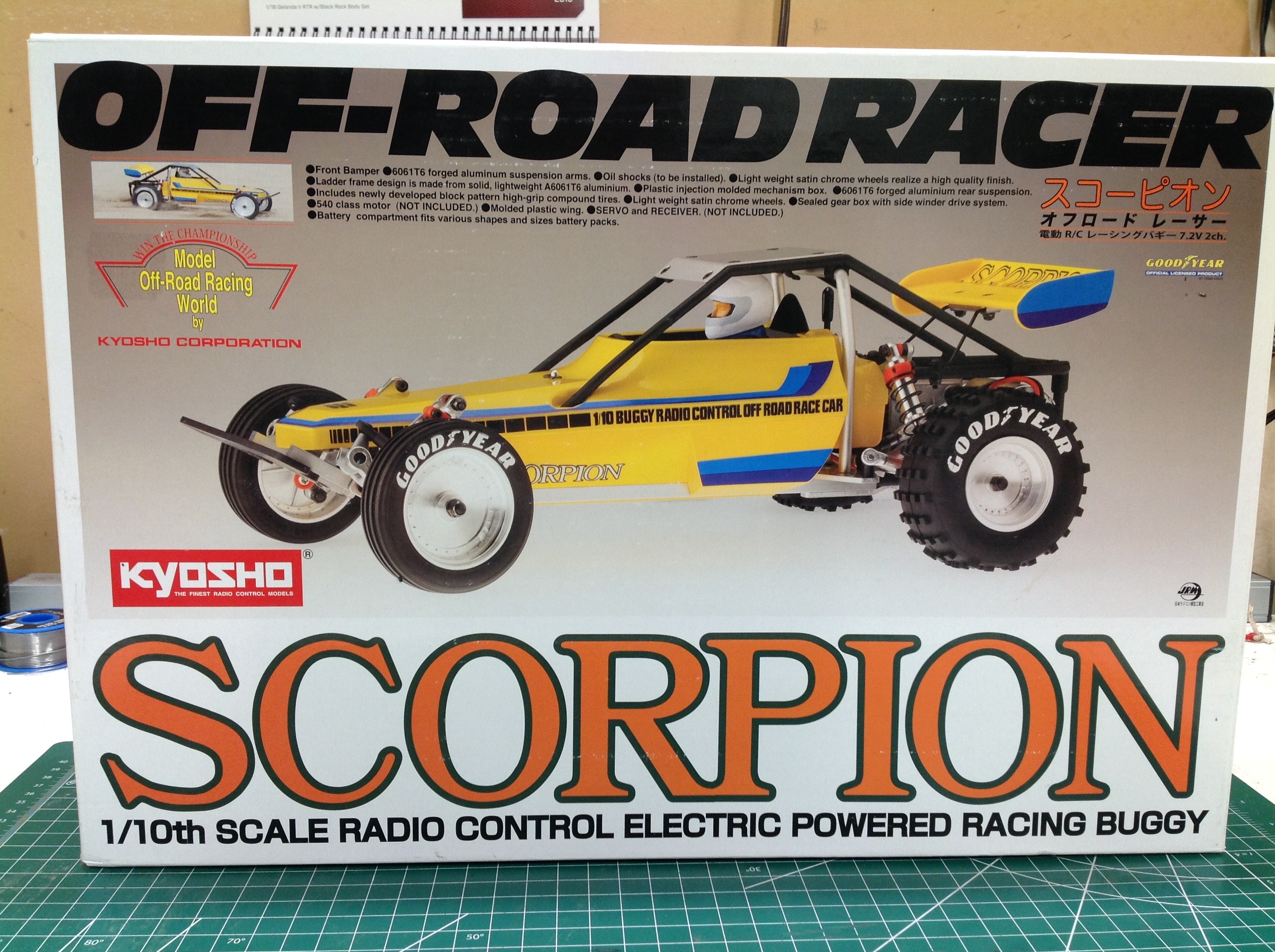
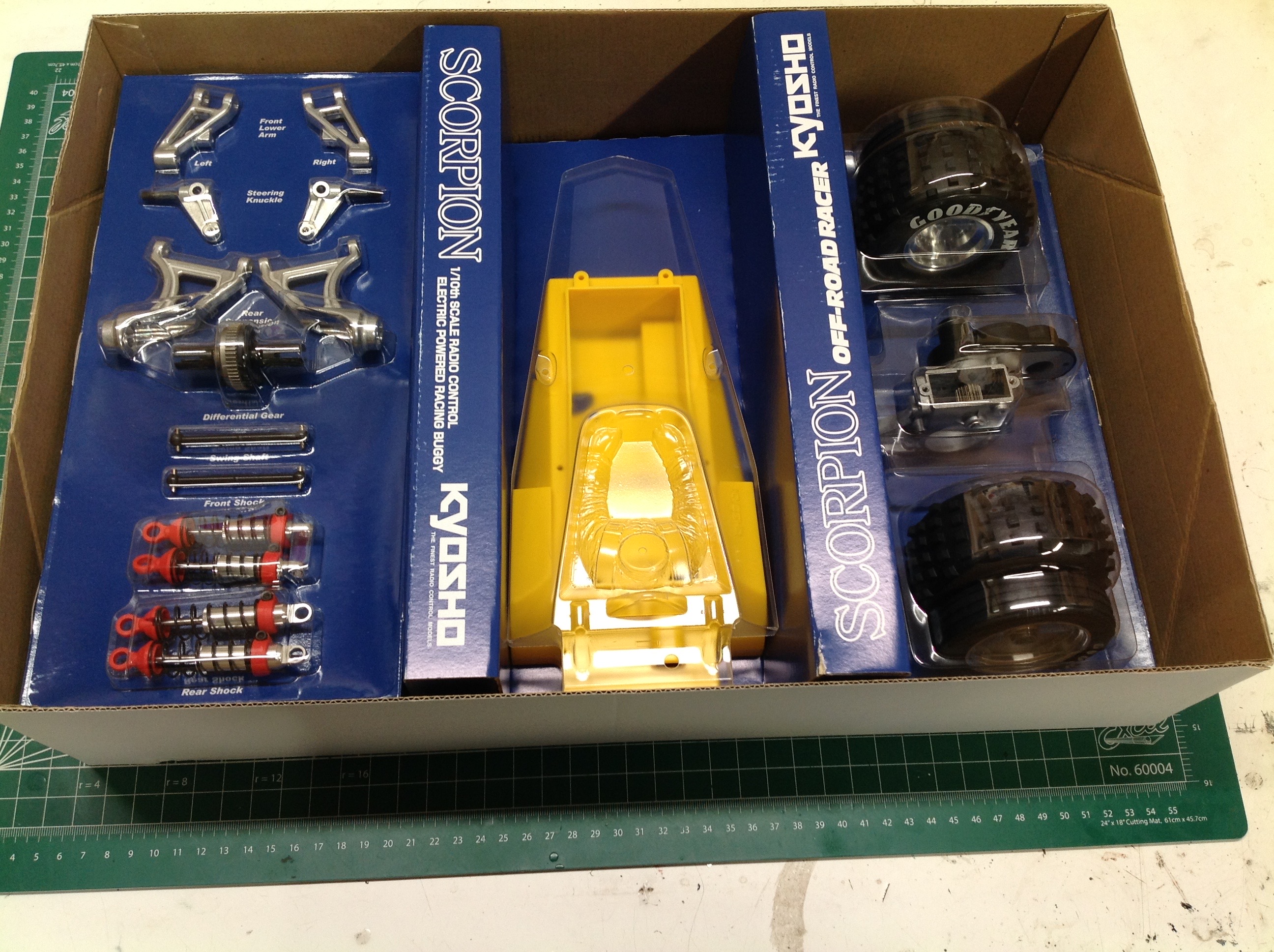
The presentation of the Scorpion parts inside the box are as beautiful
as you could ask for. The body sits in the middle with blister
packs to either side. The remaining hardware sits beneath the left
hand tray.
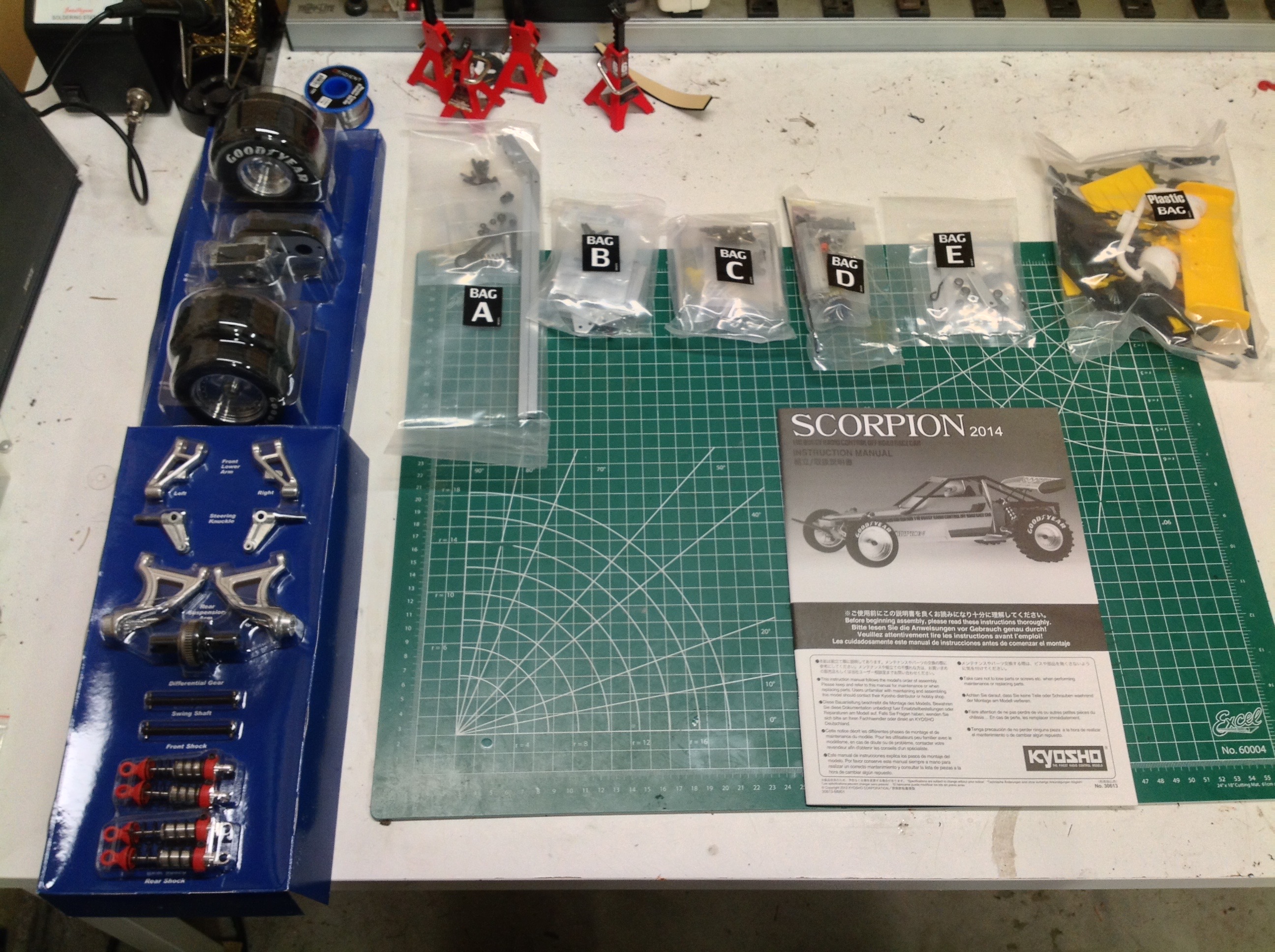
The parts are very neatly organized into five hardware bags, a plastic
bag, and the two blister packs. Note that there are very few
plastic parts. The body tub is basically it.
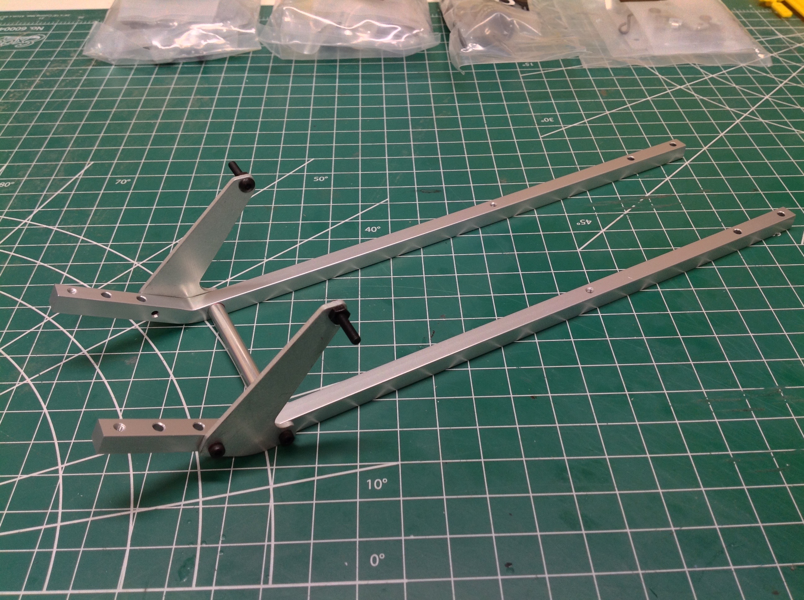
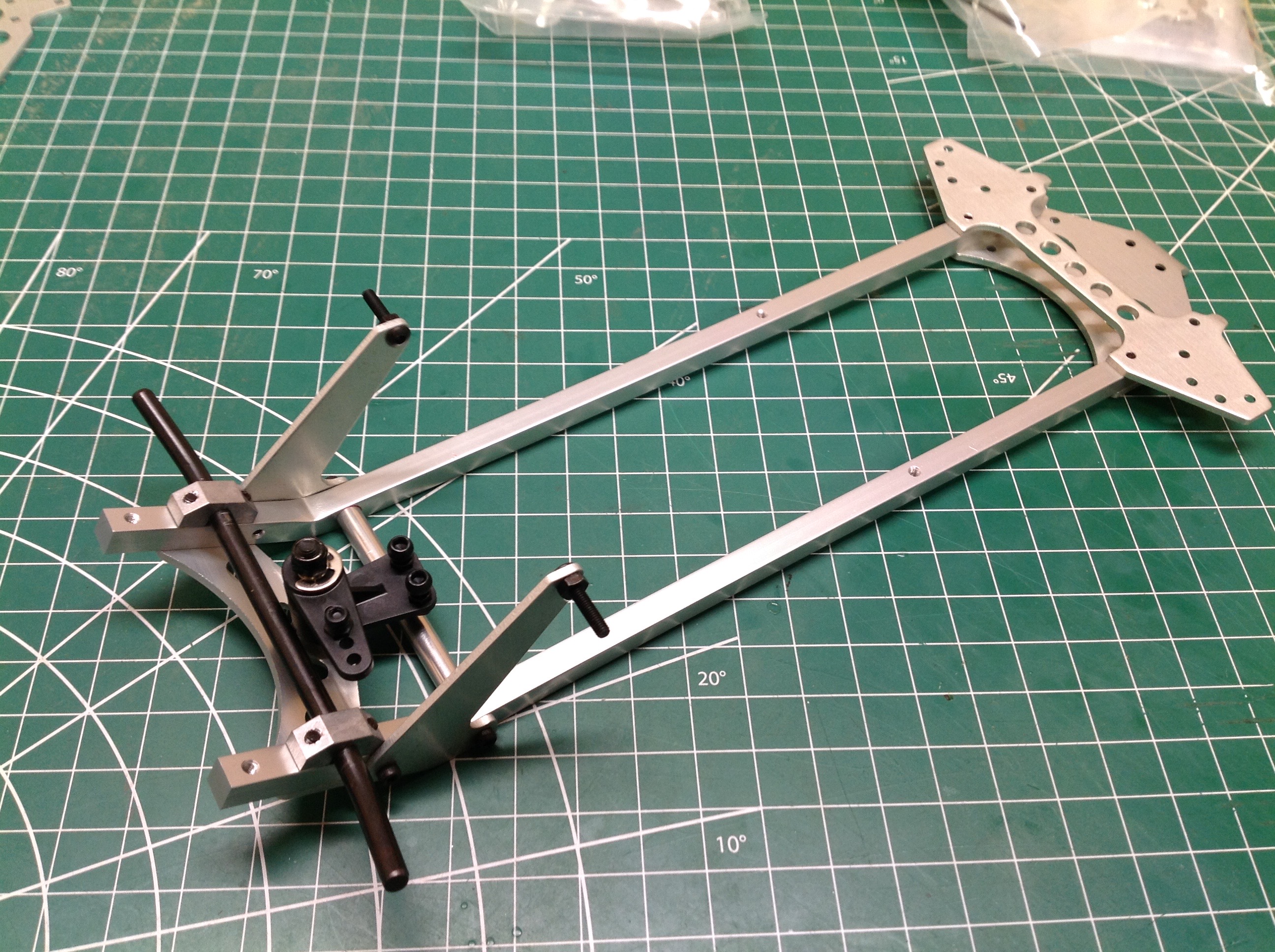
Even though the kit includes a plastic bathtub, the entire chassis is
actually aluminum. It starts with these two solid (not hollow bar
stock) square rails, front shock towers, and cross member. You can
see that the rails are bent to have a kick-up angle in the front.
The steering linkage is a simple crank with integrated servo saver as
shown on the right.
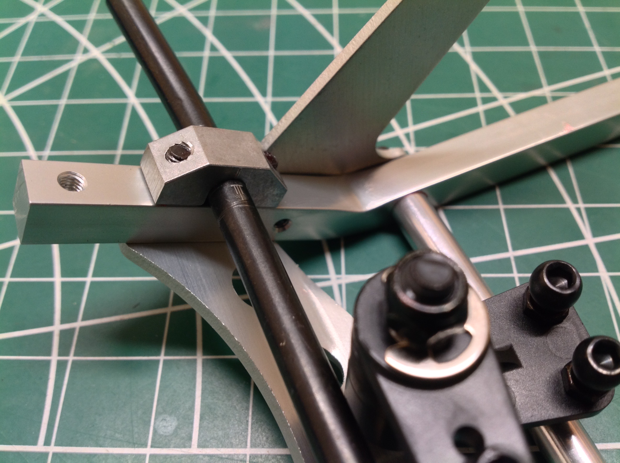
Now the steering crank can be mounted to the chassis along with some
rear cross members. The bent round bar which crosses the front is a
very unusual suspension mount. It serves as the rotation axis for
the front trailing arms. The whole rod can be rotated in the
pillow blocks to change the caster angle. Look closely at the
picture on the right and you can see the scale printed onto the bar
which shows the nominal adjust point in the center and allows adjustment
to either side.
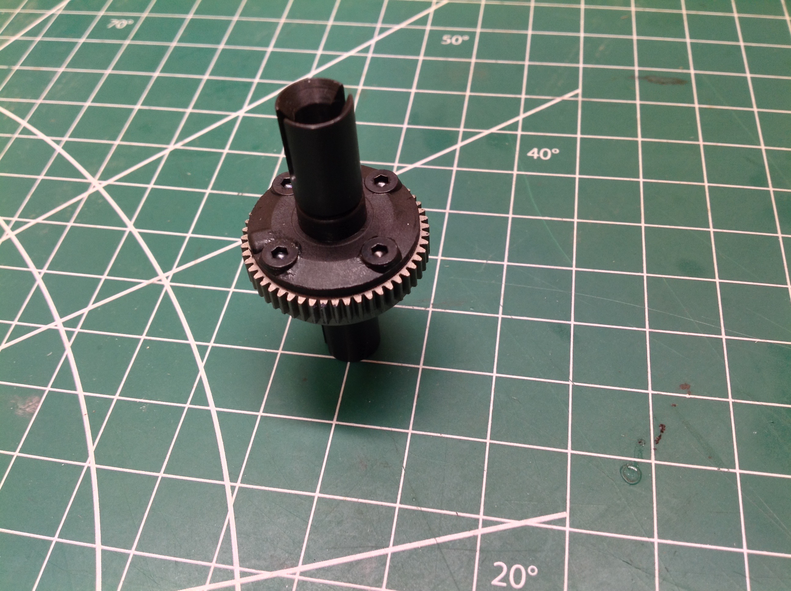
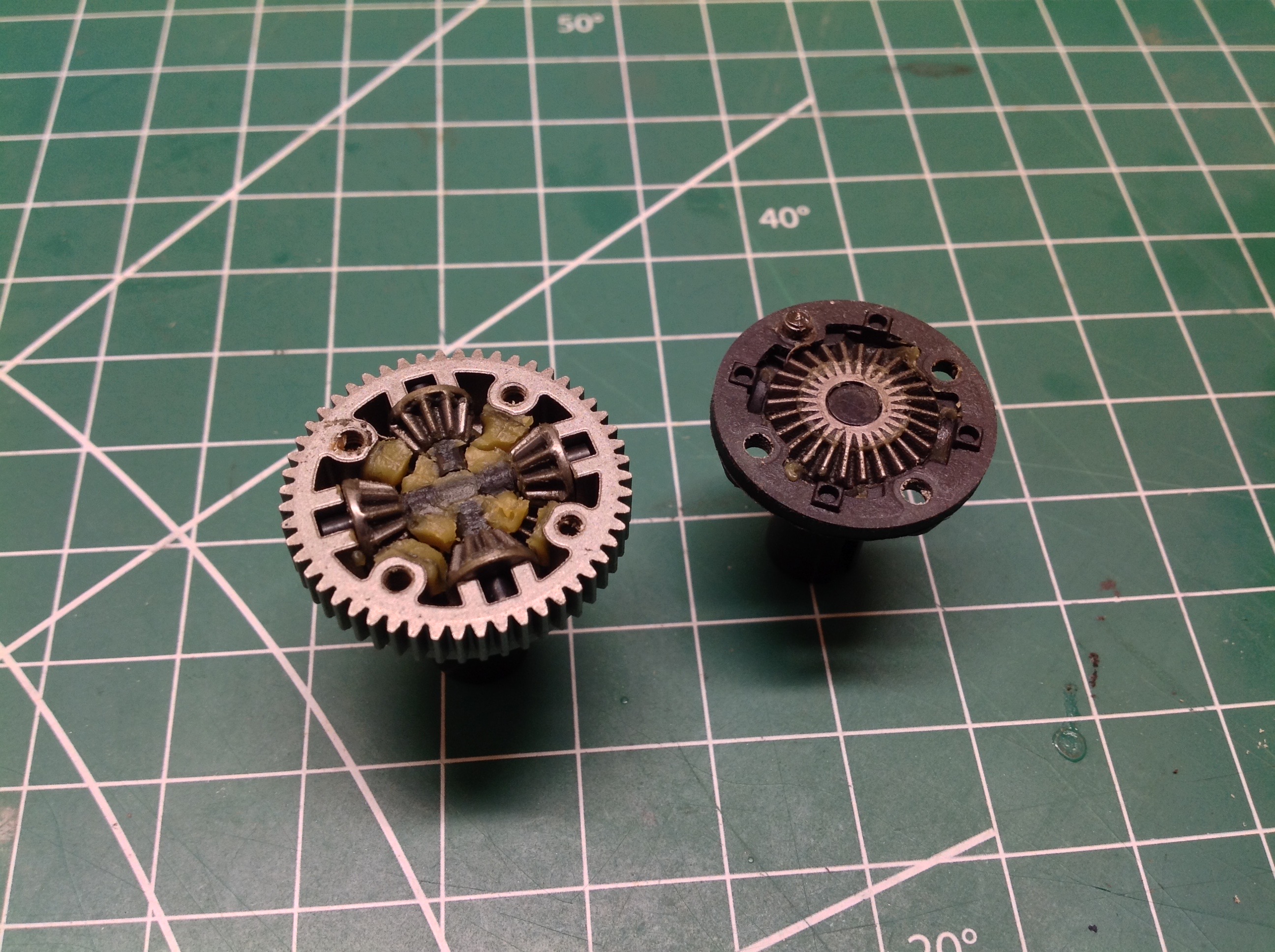
The single differential came pre-assembled in the package, but of course
I had to take it apart both to see what was inside and to check for
adequate grease. The grease I found was ample but seemed more like
a paste than a viscous fluid. I was happy to see all metal gears.
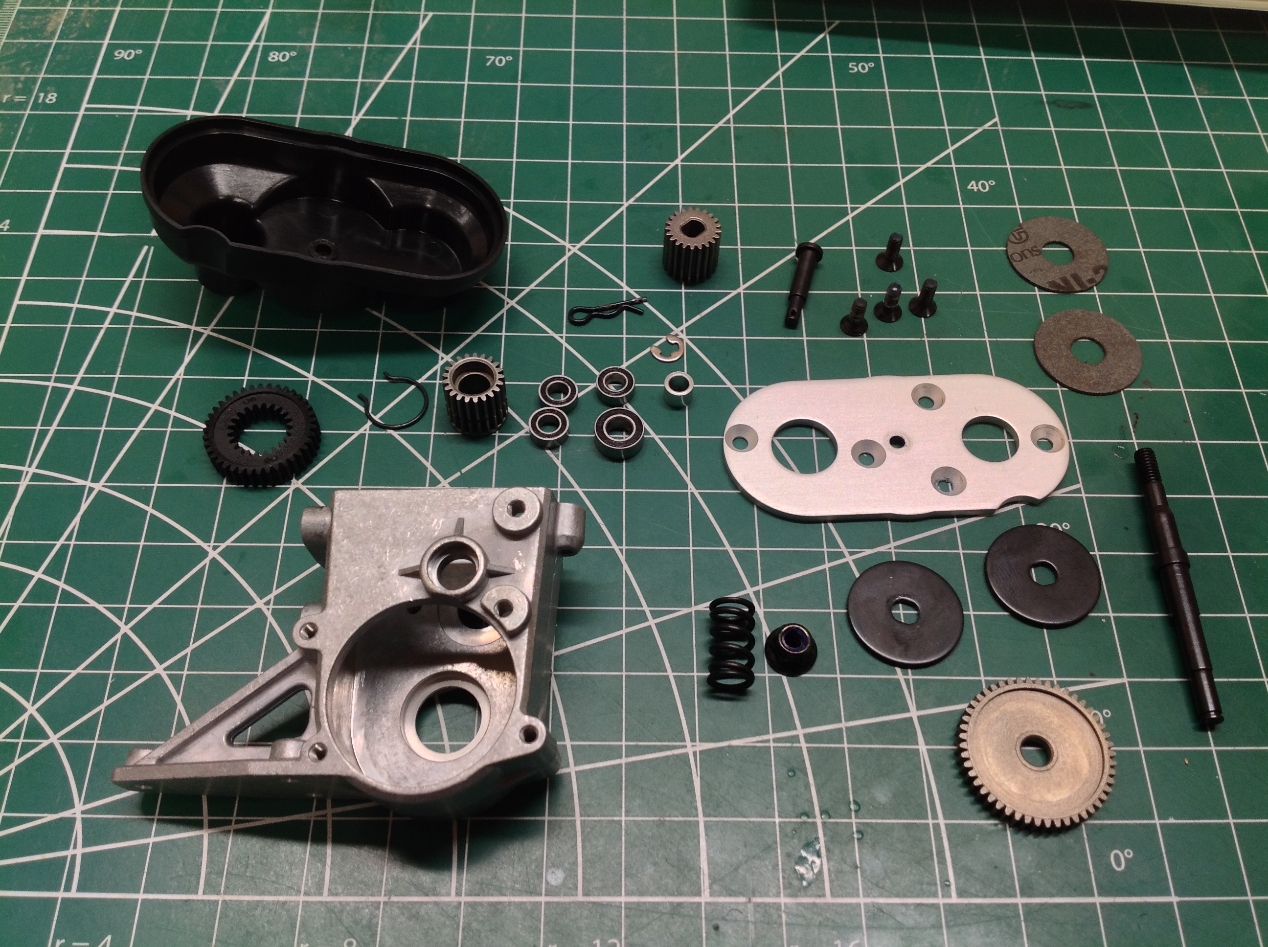
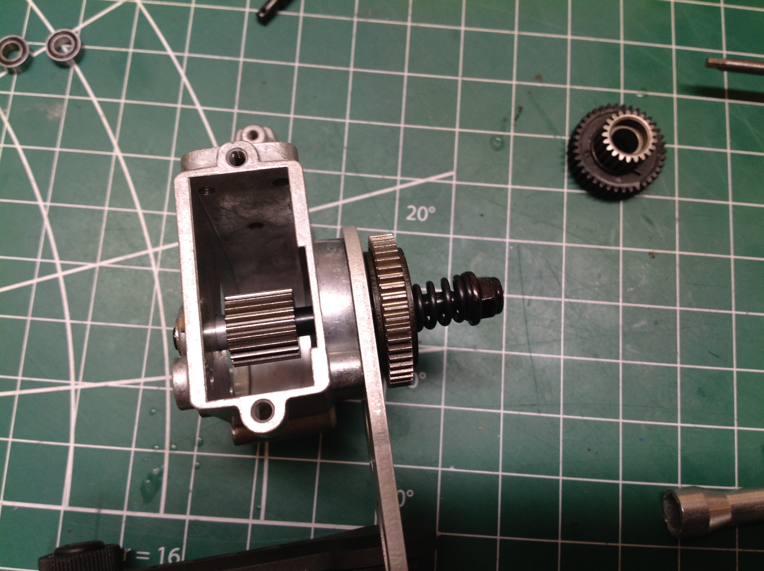
The gearbox was also pre-assembled which is really unfortunate because
it contains so much good stuff. I totally tore it down as shown on
the right. The are a lot of parts inside including the slipper
clutch.
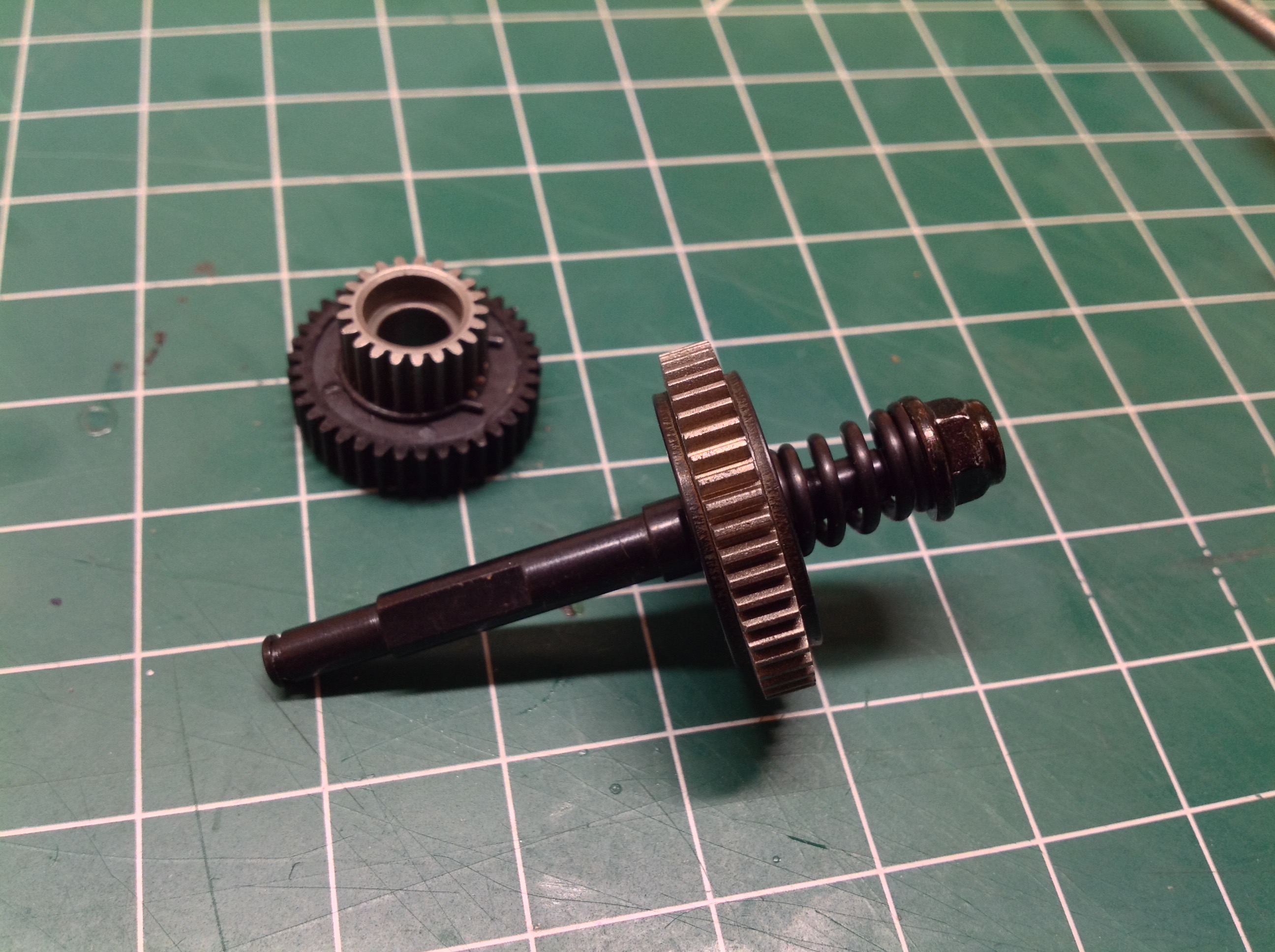
The slipper clutch has two friction surfaces and sits outside the
gearbox while a smaller spur gear sits inside. The idler gear
shown sitting next to the gearbox is one of two optional assemblies
allowing the choice of either a 6.9:1 or 8.3:1 ratio.
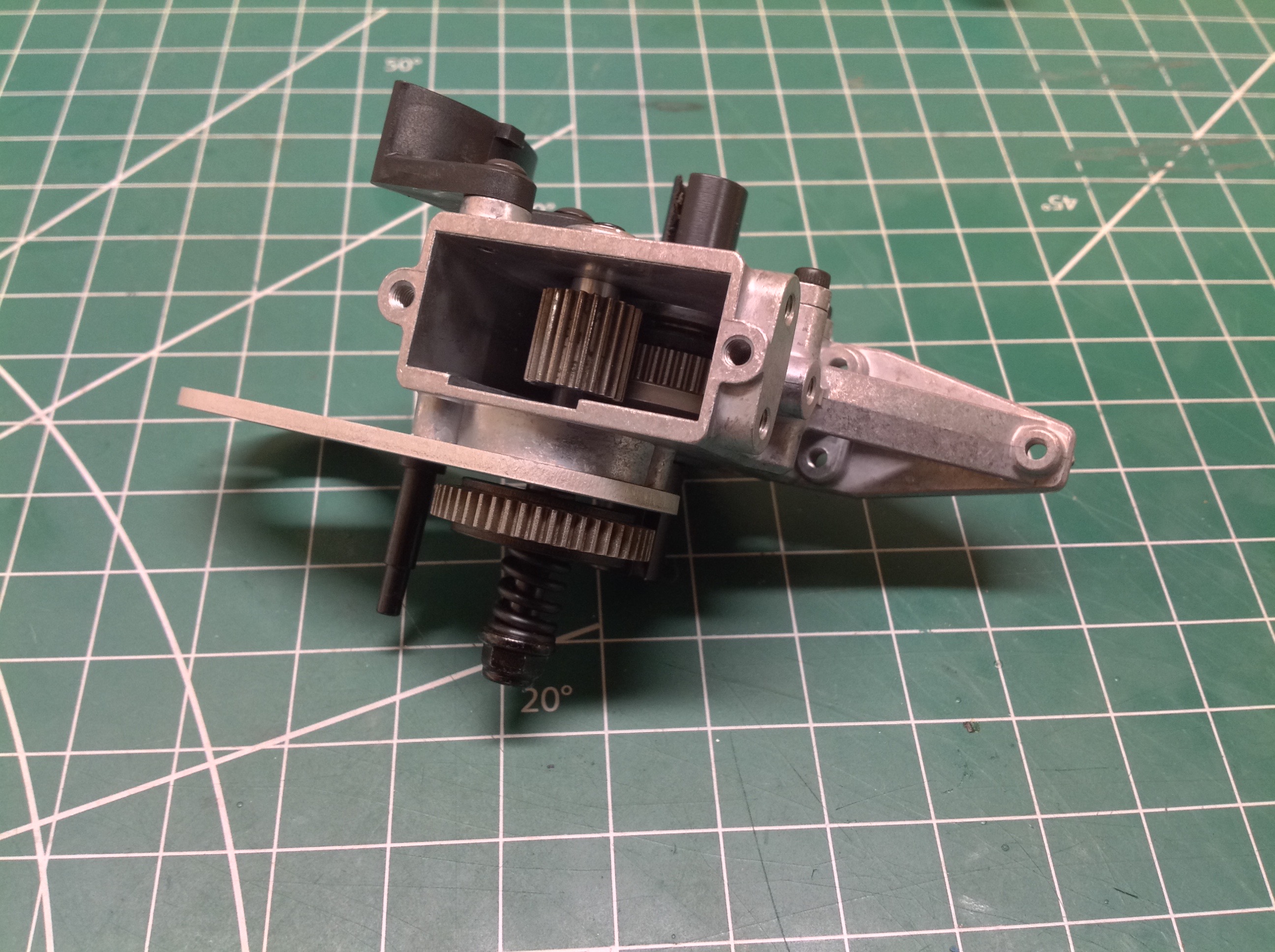
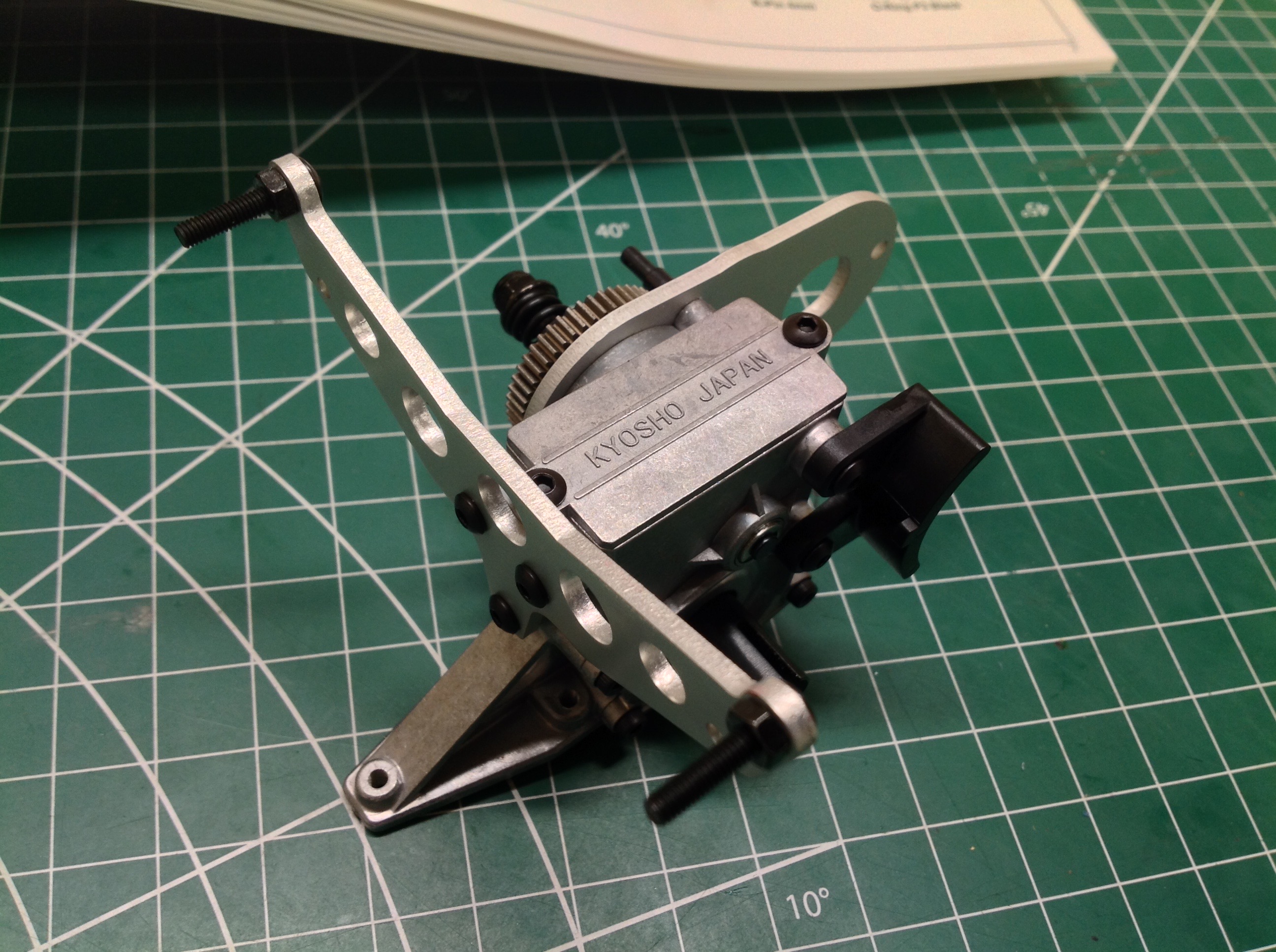
Now the diff gear plugs into the bottom and meets the internal spur
gear. After application of some grease, the top cover and rear
shock tower can be attached to the gearbox housing.
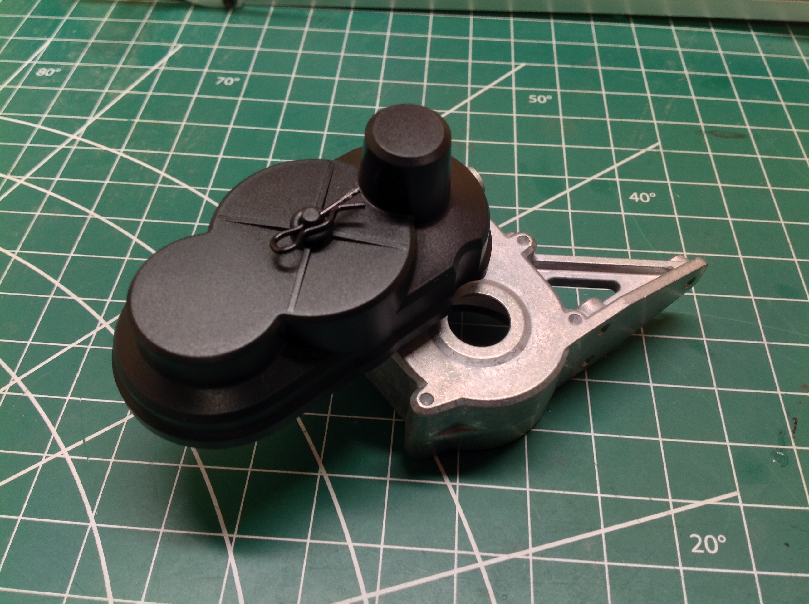
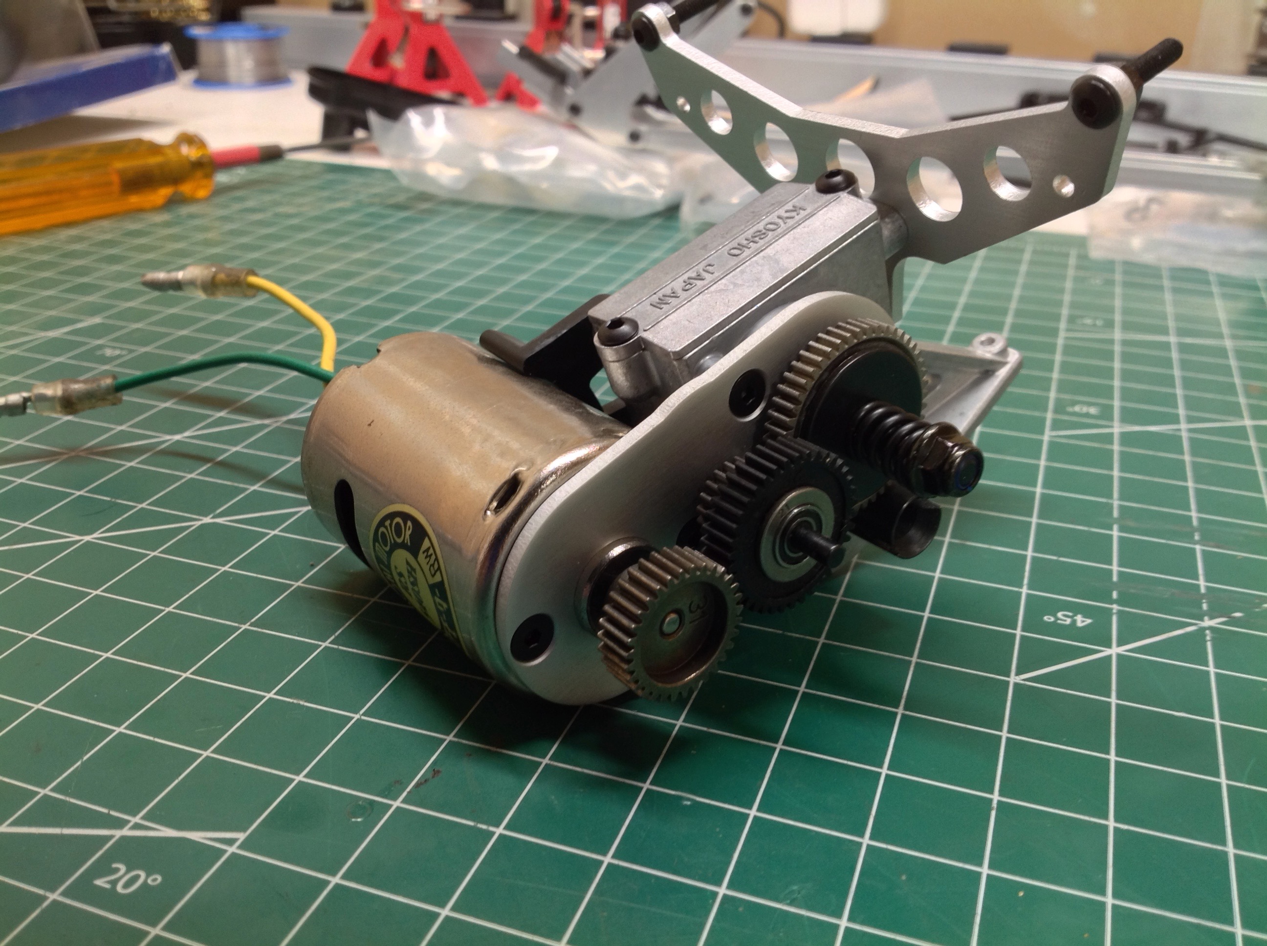
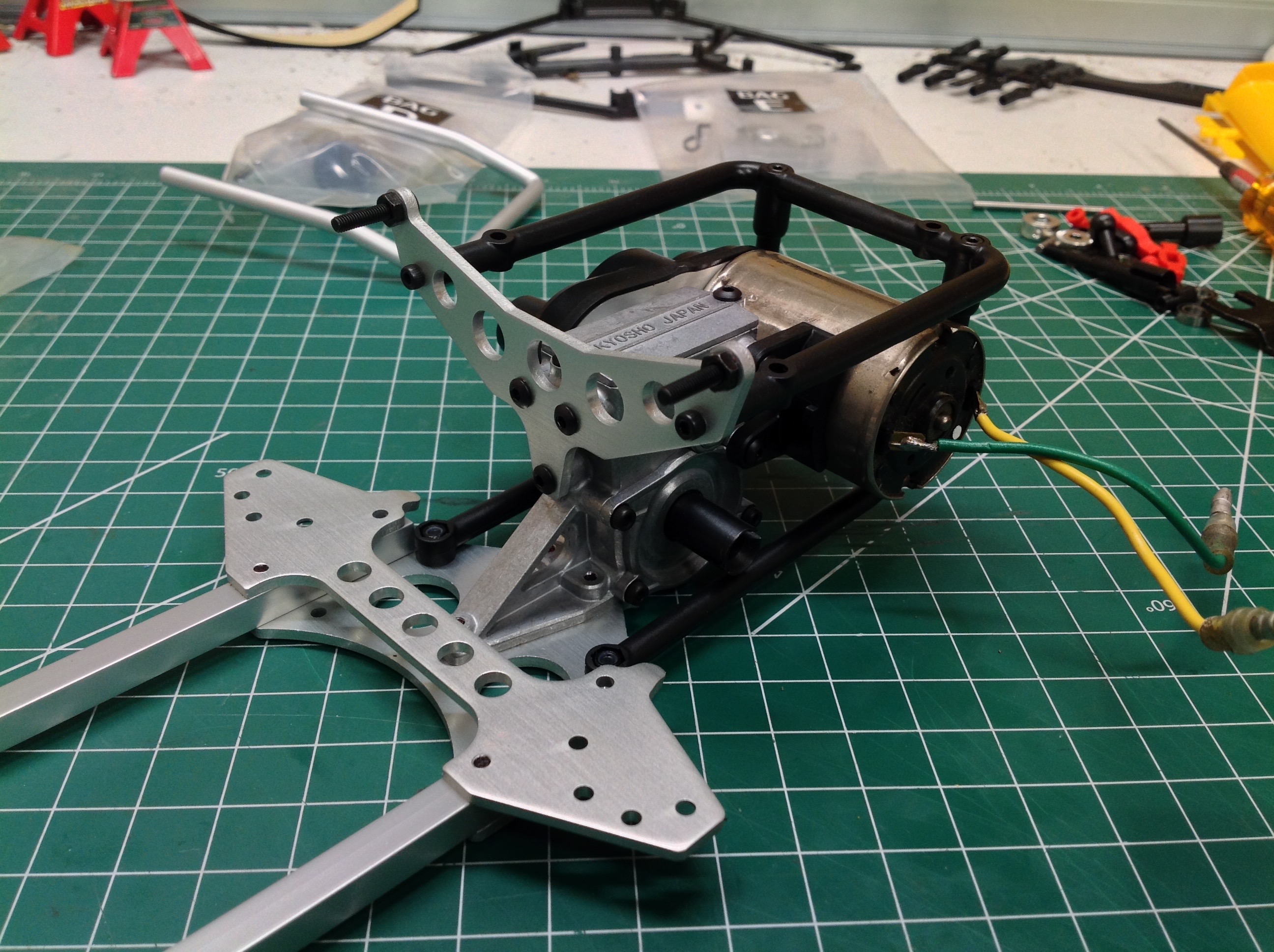
Here's the completed power assembly using a temporary Tamiya silver can
motor as a placeholder until I choose a power system. The whole
thing then bolts to the rear chassis cross member. Note the
plastic cage surrounding the gearbox.
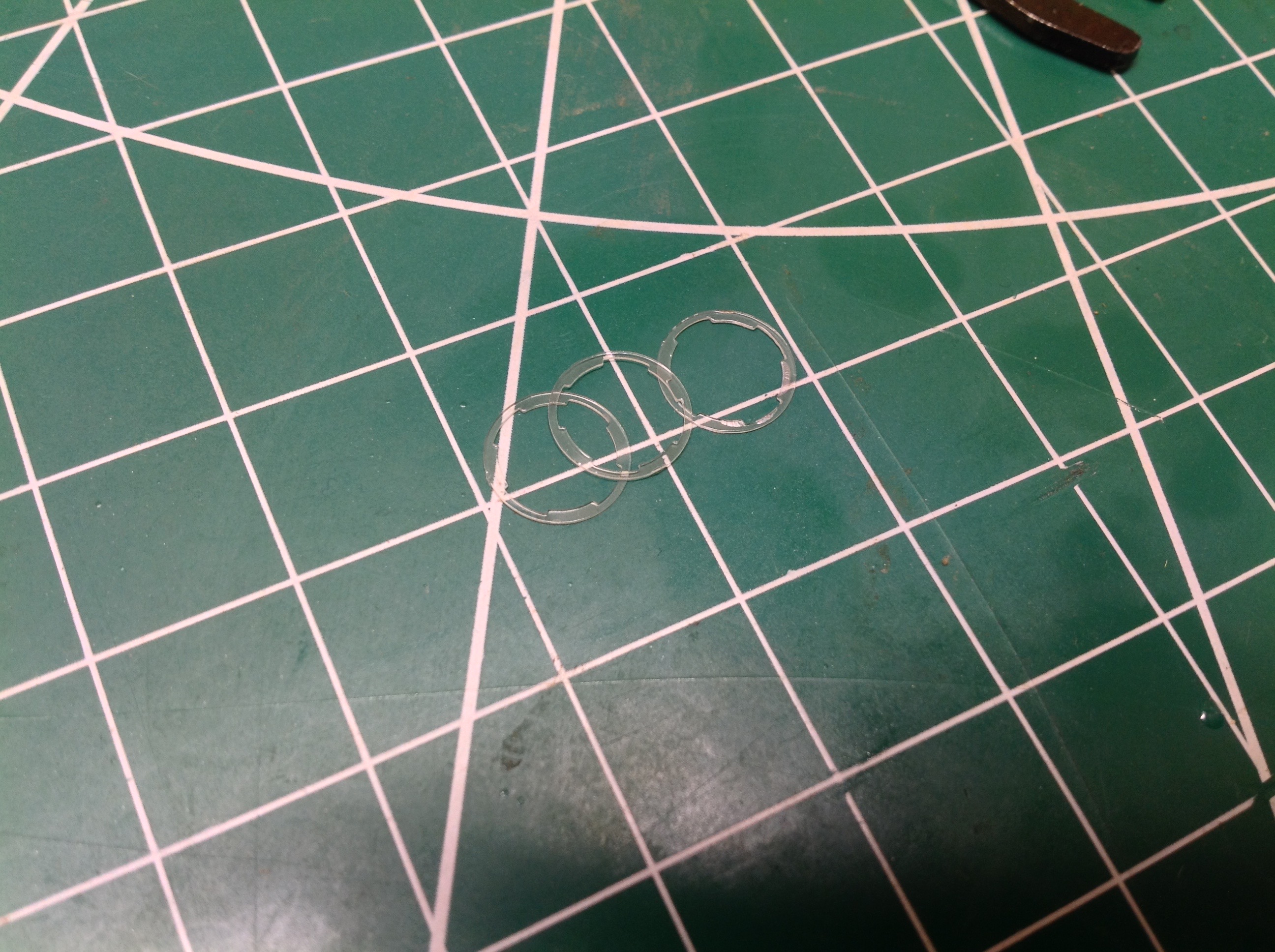
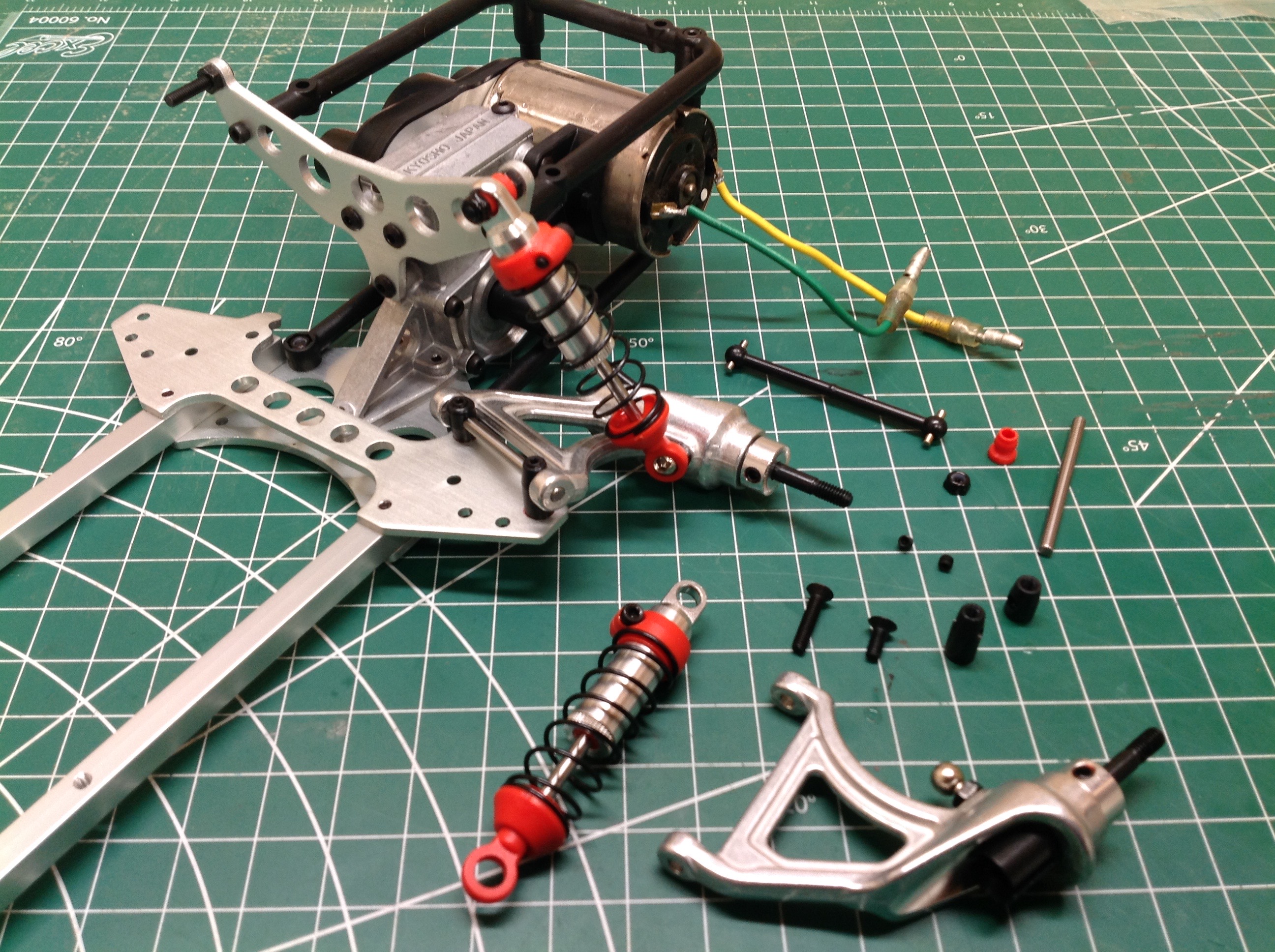
See those tiny clear seals in the picture on the left? Neither did
I. I was convinced that these parts were missing from my kit
until I found them hiding inside a bag I'd emptied and thrown out.
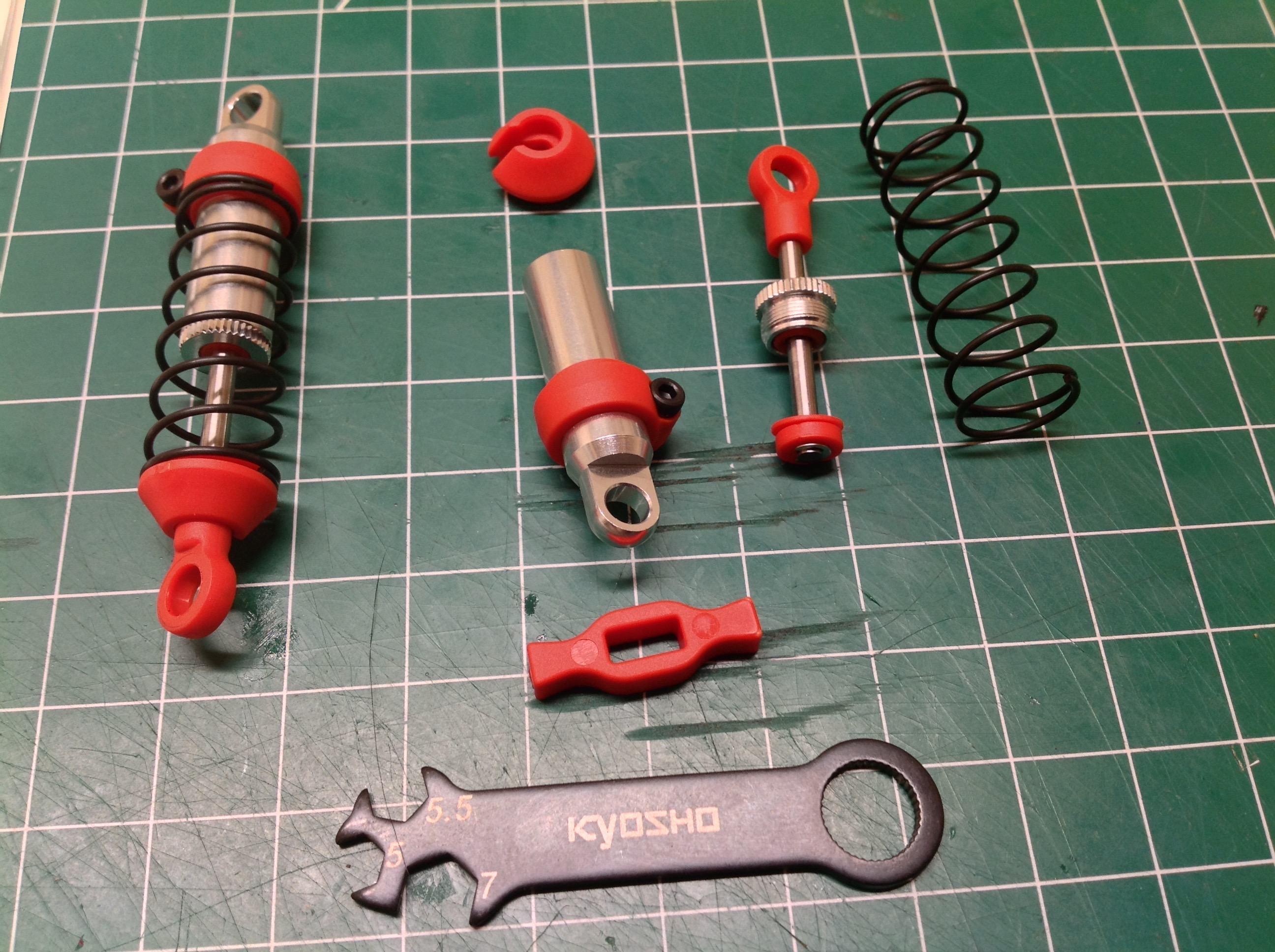
These are the gland seals for the shocks. The shocks come
pre-assembled but must be disassembled to the extent shown on the right
to fill them with oil and install the seal. There's a diagram in
the back of the manual showing you how to fully tear down the shocks if
you ever need to. The special tools shown make this process a lot
easier.
The rear suspension is very odd. It's not exactly trailing arm but
it not exactly swing arm either. The pivot axis for the
suspension arm is mostly lateral, but is angled slightly forward and
tipped slightly up as well. How they came up with this particular
geometry I can't say, but it results in a very small change in wheelbase
and a small change in camber as a function of suspension travel.
This is apparently called a semi-trailing arm suspension and allows the
pivot axis of each wheel to intersect the contact patch of the opposite
wheel. The understeering tendency of a trailing arm and the
oversteering tendency of a swing arm theoretically cancel out. I
have never seen its like in another model.
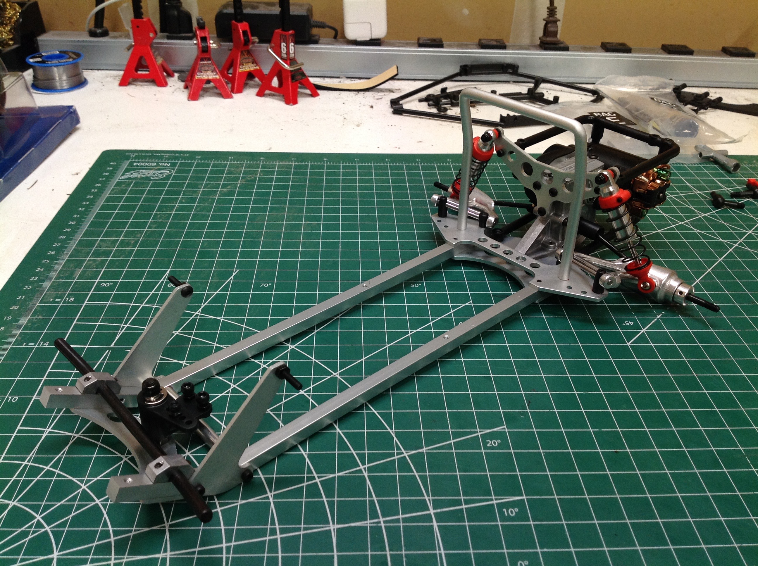
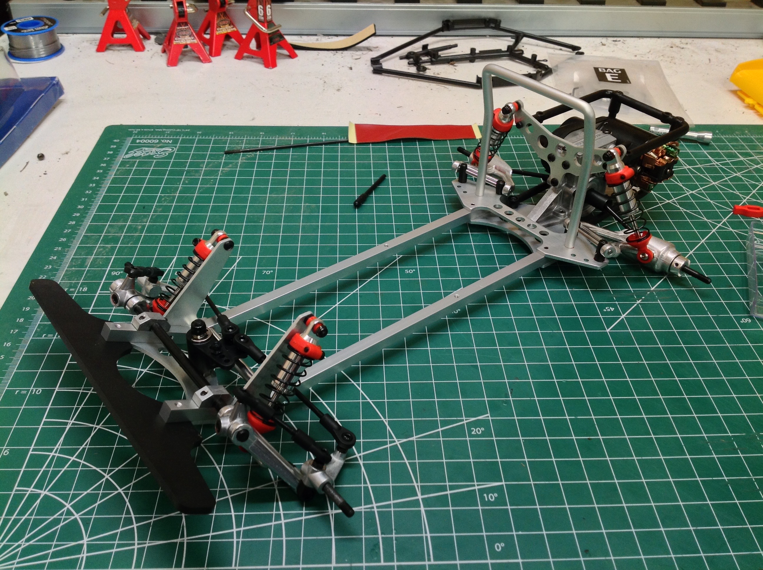
The rear suspension and drive system are now complete. The chassis is obviously very weight biased toward the rear.
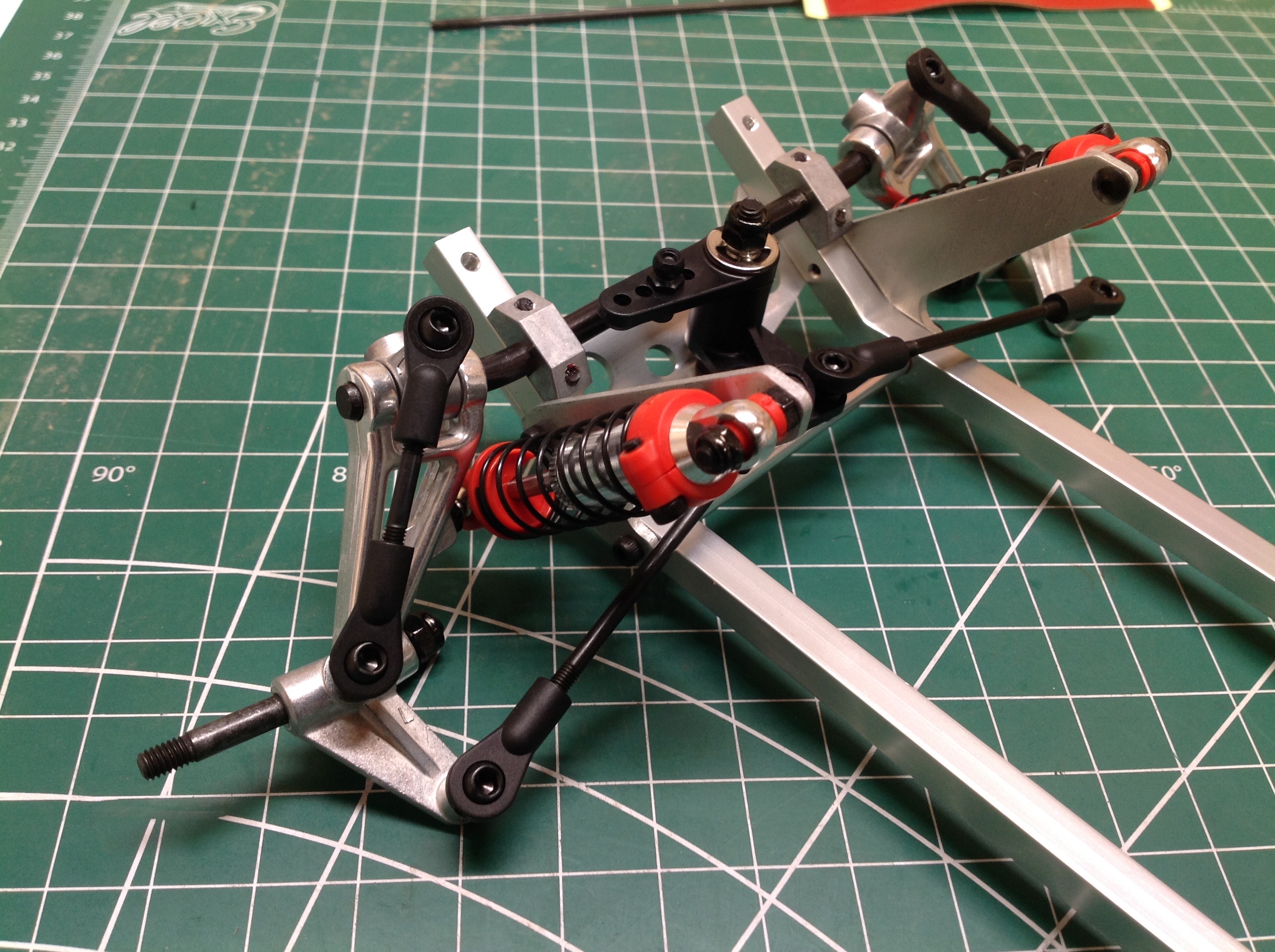
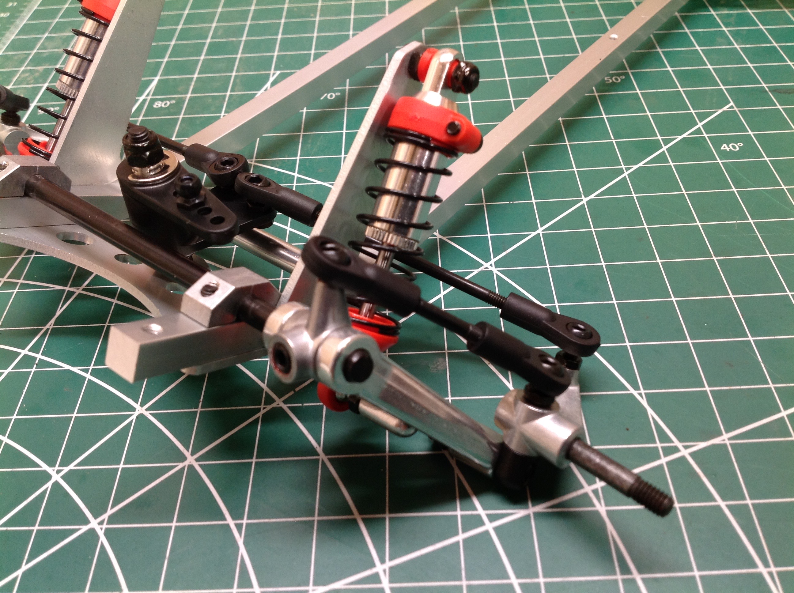
Like the rear, the front suspension using something approximating a
semi-trailing arm design. However, there is also an upper arm
which makes it a type of double wishbone. Again, this is a totally
unique suspension setup so far as I am aware.
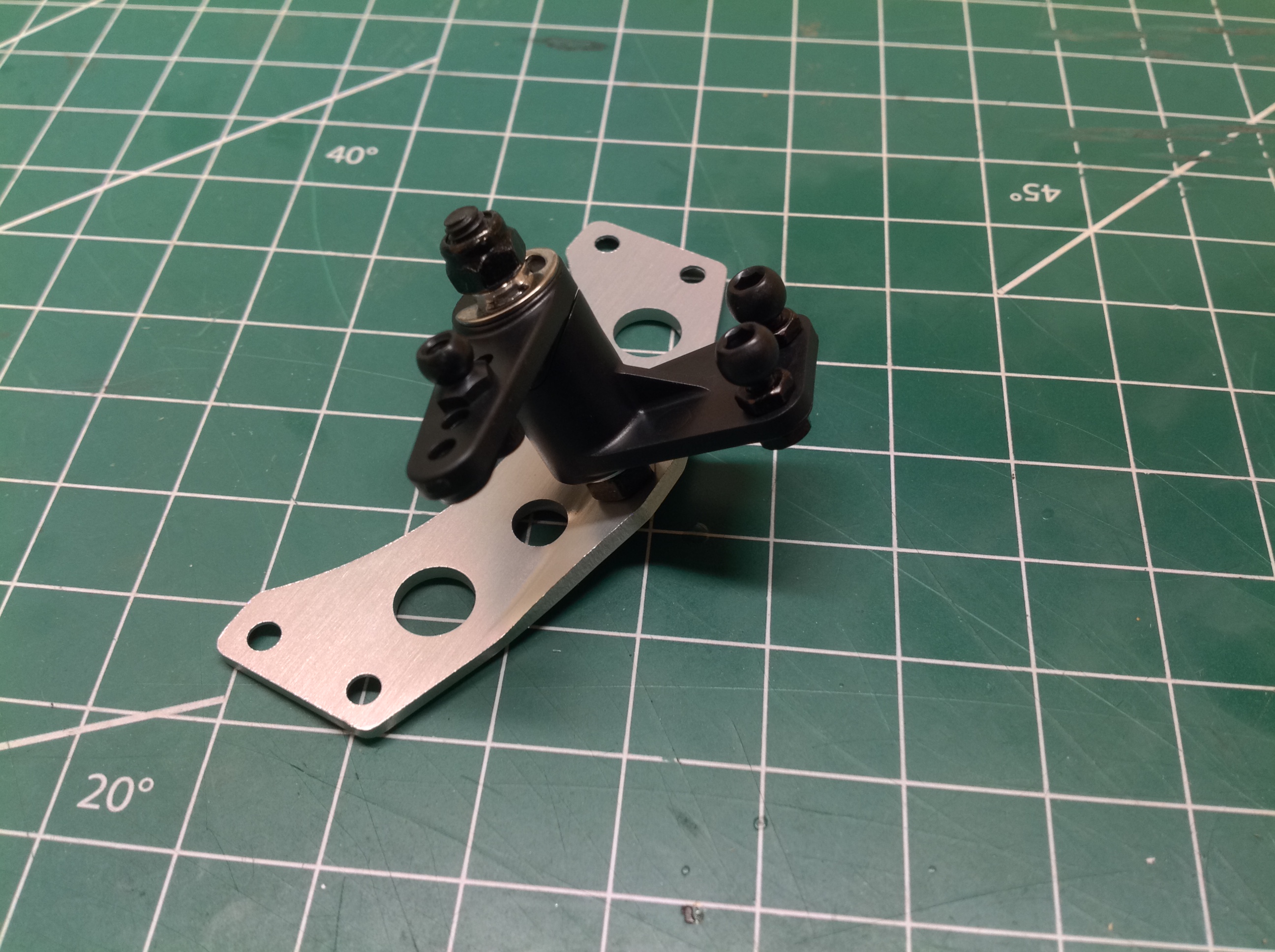
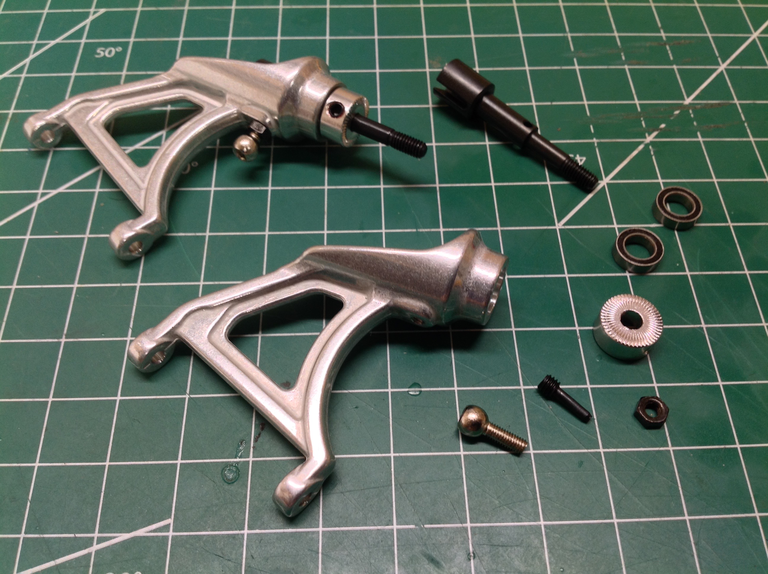
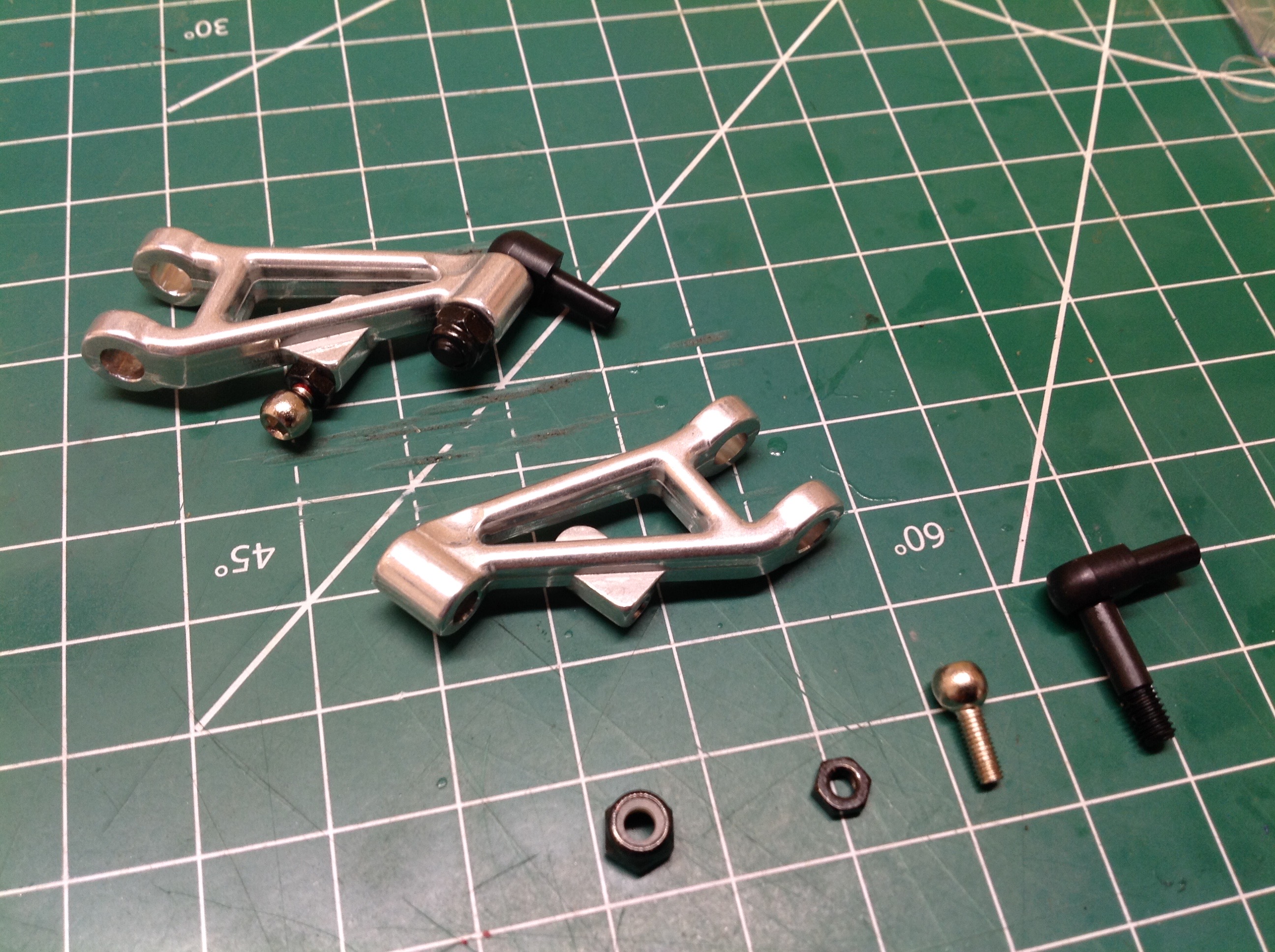
Here's a closer look at that front suspension. In order to have an
upper suspension arm it has to be attached to a point higher on the
chassis than the lower arm, but the pivot axle is the only attach
point. To solve this they have installed a standoff crank with a
ball joint as shown. This whole crank can be clocked on the pivot
axle to set the camber angle of the steering knuckle. It's very
difficult to get right because there is no good datum against which to
reference. The instruction say to allow a certain gap between the
steering tie rod and the frame at full suspension extension to set the
angle. Crude, but effective. Make sure that the set screw
which locks the orientation is nice and tight or it will rotate the
first time you go over a bump. Once everything is set, the front
bumper can be attached as shown.
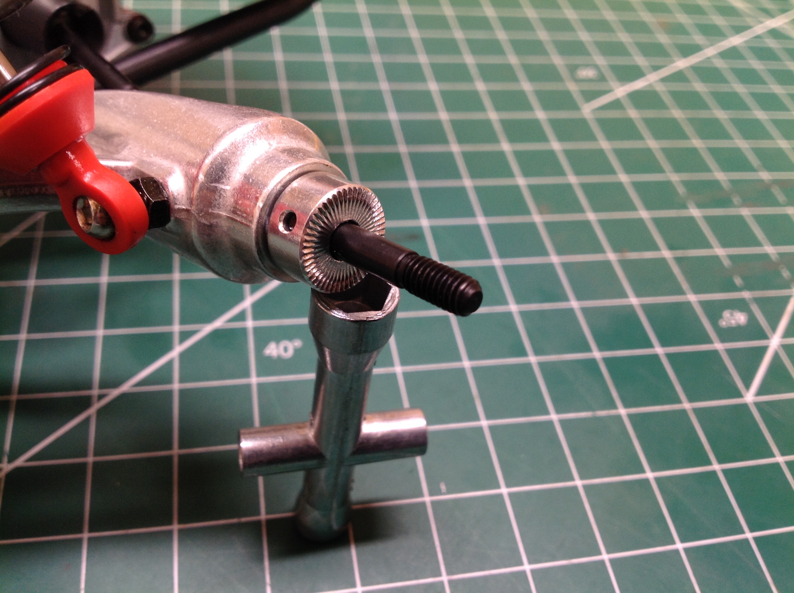
Even the wheel hub is odd. Normally you would see a 12mm hex (or
something similar) to transfer the torque of the driven axle to the
wheel. In this case, we just have a serrated nut. The
clamping force of the wheel nut against the serrations is all that
provides the preload necessary to engage the serrations. A loose
wheel nut will result in a loss of torque before the nut actually falls
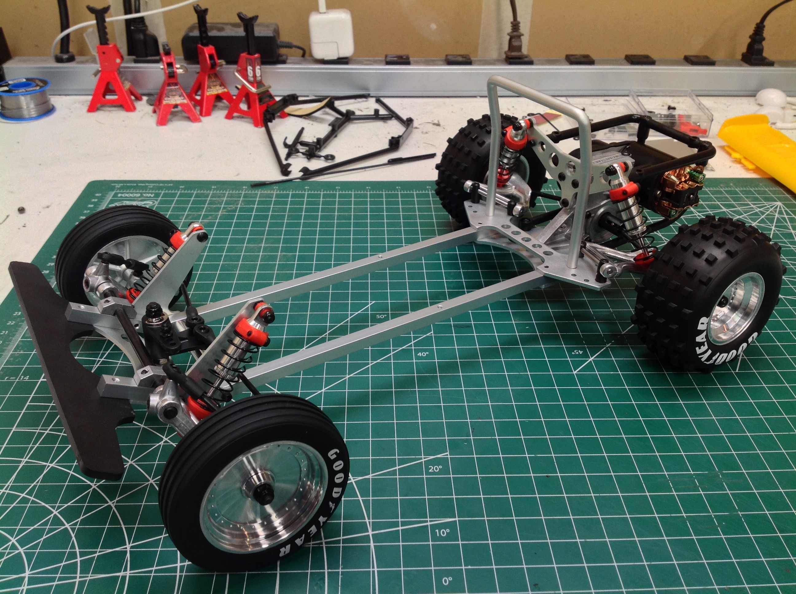
off which is actually a nice benign failure mode. To complete the
rolling chassis the wheels and tires are now installed. These are
beautiful faux brushed aluminum wheels with printed tires. It is
hard to imagine a bigger size and tread pattern variation between front
and rear tires. At this point you can also see the 23T Yeah Racing motor that I've installed.
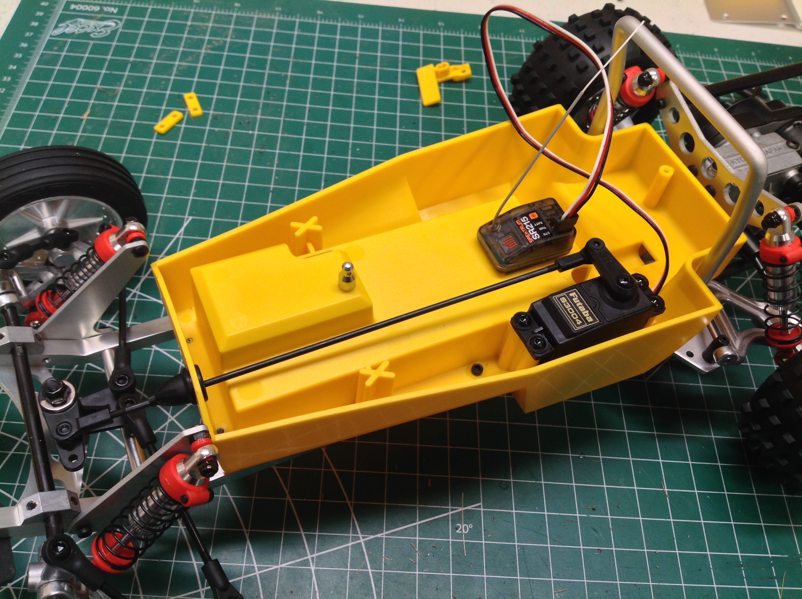
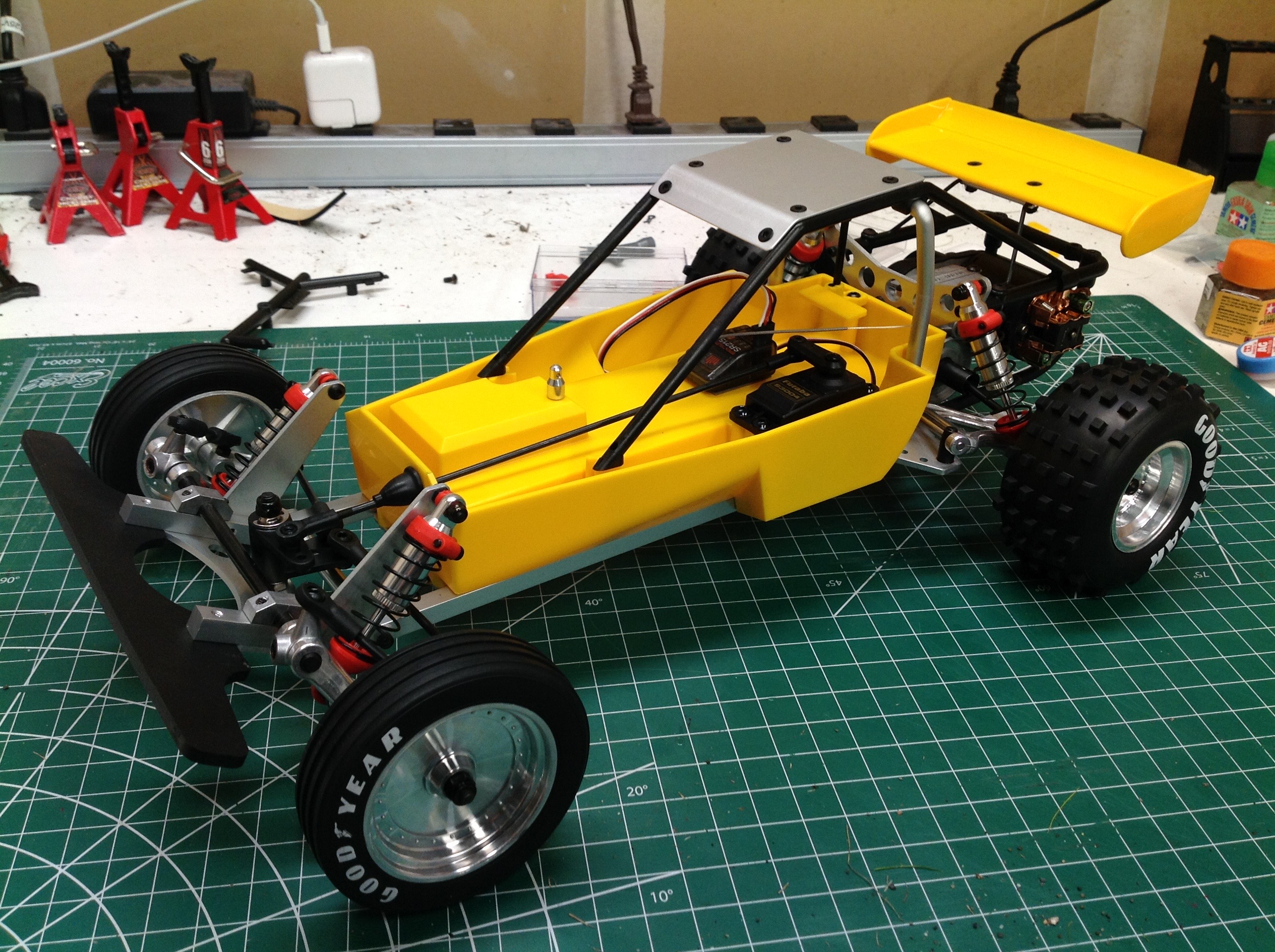
Normally a plastic bathtub forms the backbone of the structural chassis
of a radio control buggy, but in this case the tub just sits atop the
frame so it can be considered a body-on-frame chassis. The tub
houses the electronics and the roll bar while the wing attaches
separately to the motor guard. The battery installs from the
underside between the frame rails.
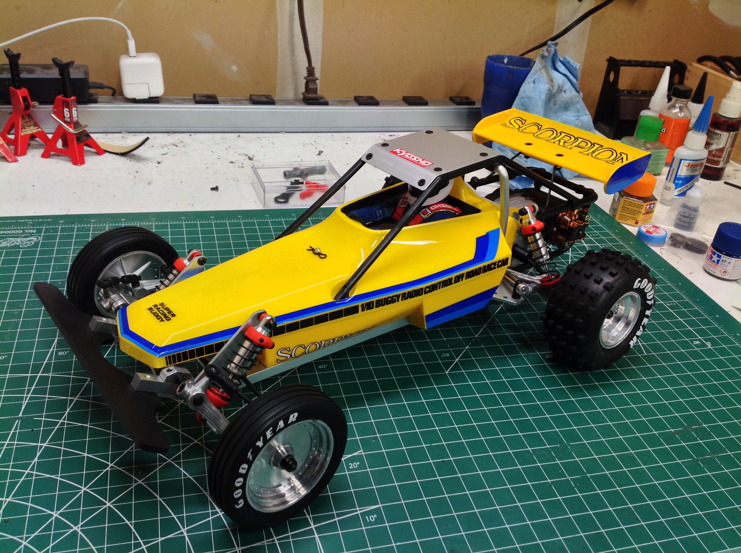
The driver is actually part of the polycarbonate cover that sits on top
of the plastic bathtub. This is the only kit I have built to use a
combination of hard plastic and polycarbonate for the body shell.
©2020 Eric Albrecht