Fijon FJ9 Project
Page 1: Assembly
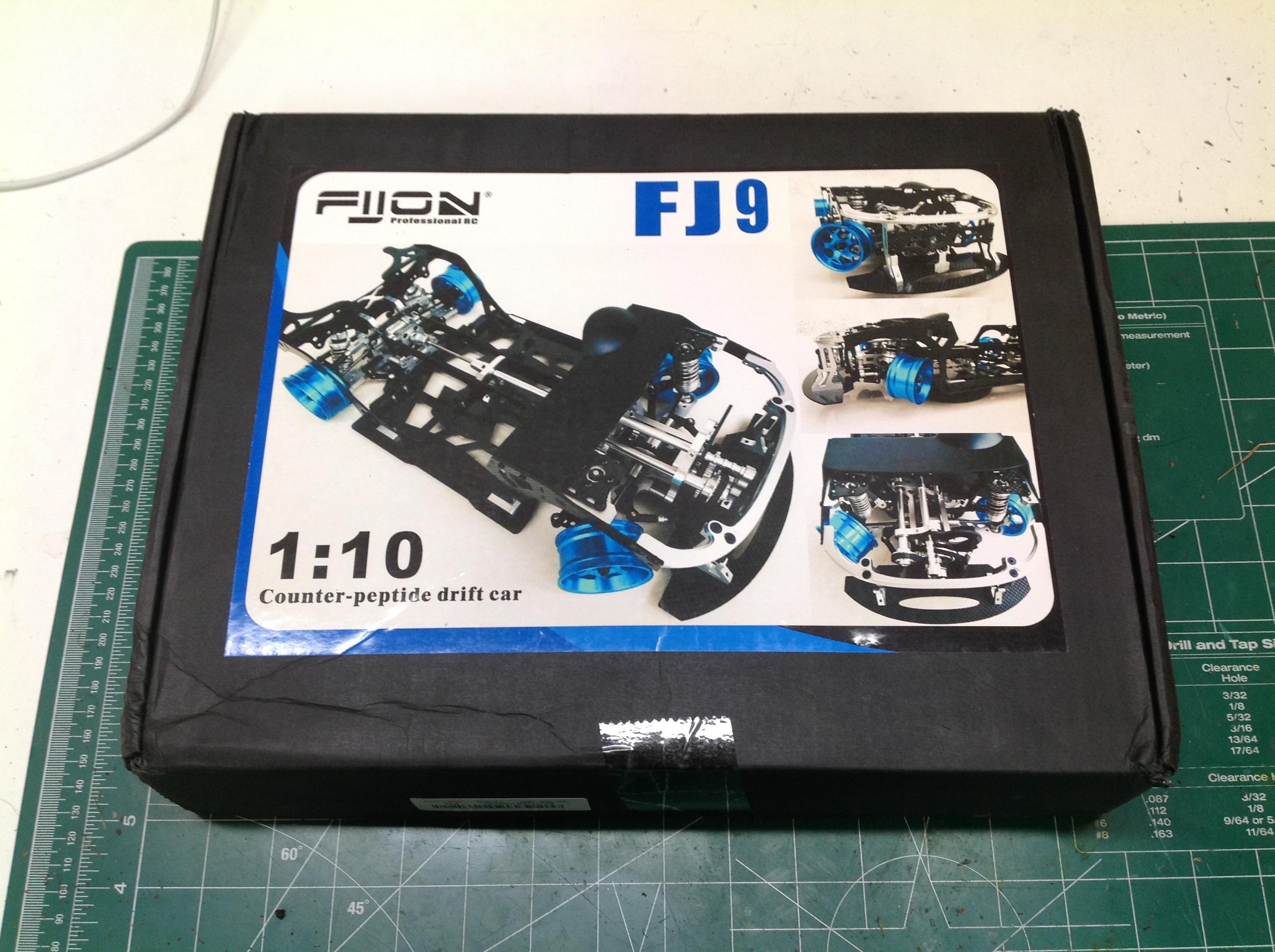
The FJ9 comes in a rather non-descript box with some very strange
wording. It refers to this as a "counter-peptide" drift car by
which I assume they mean "counter-steer". Counter-steer isn't a
very good term either because it has naught to do with counter steering
(which is a real thing). In the context of an RC drift car it just
means that the rear axle is geared higher than the front. The
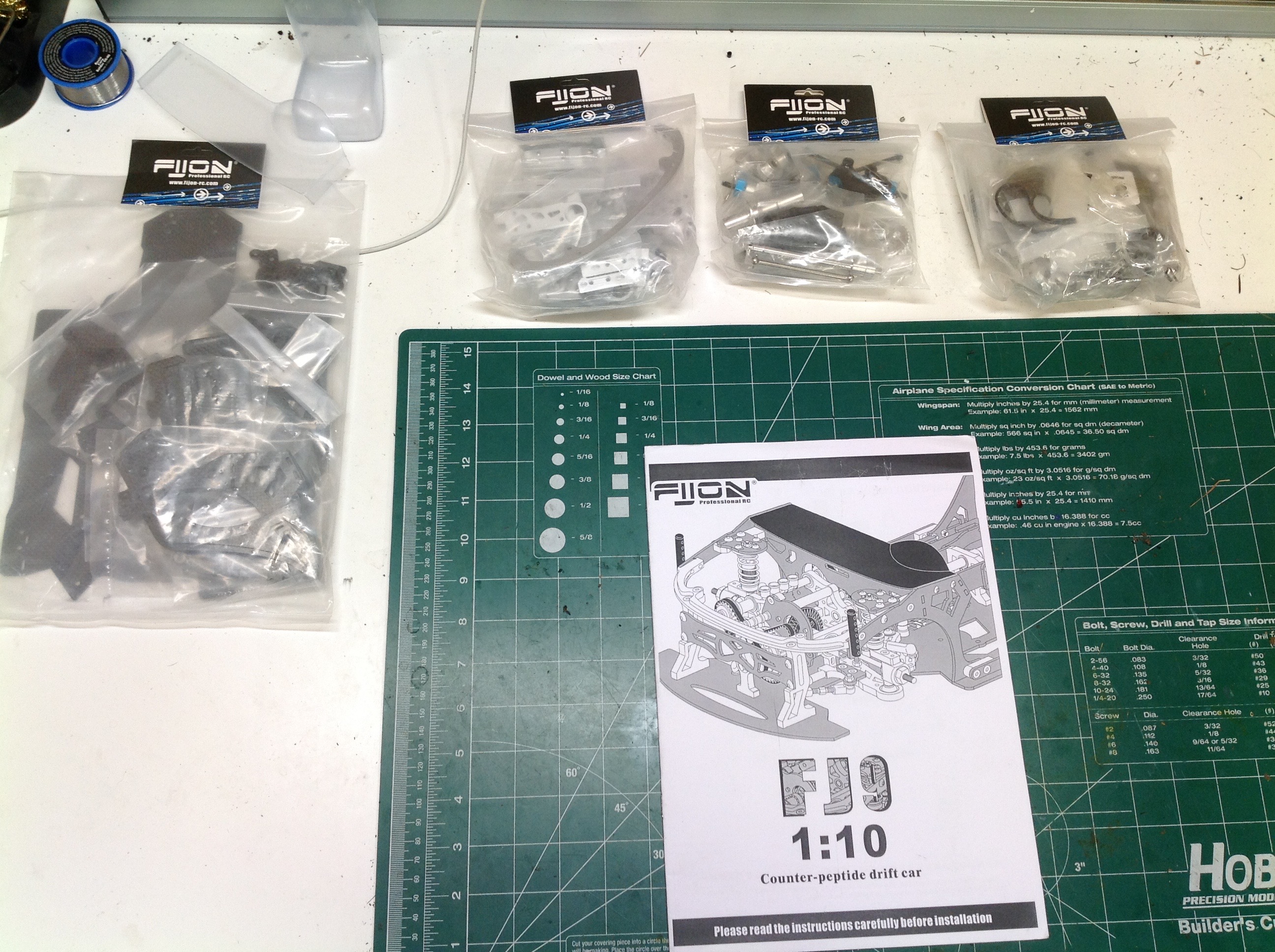
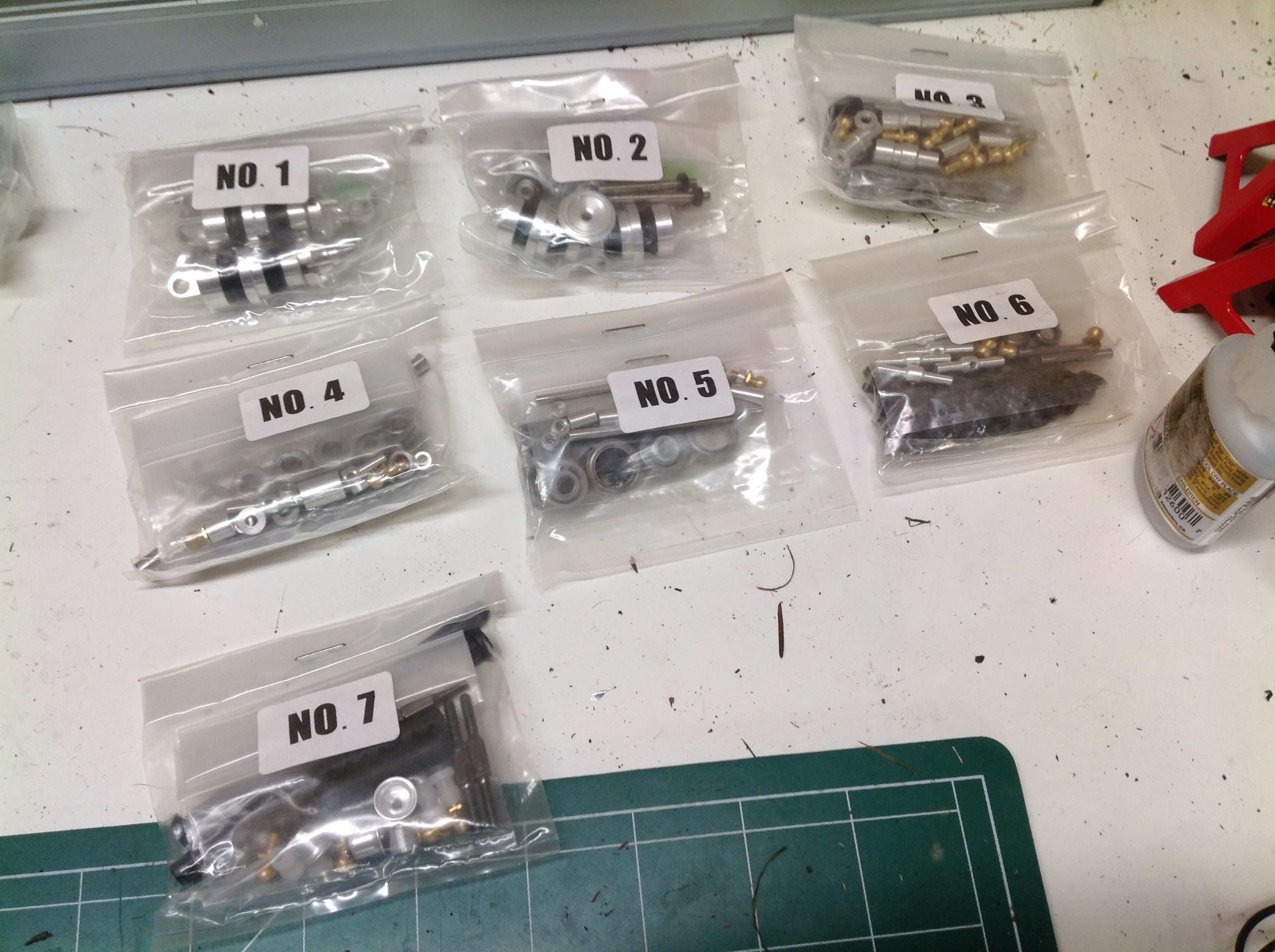
parts inside are divided into bags as shown.
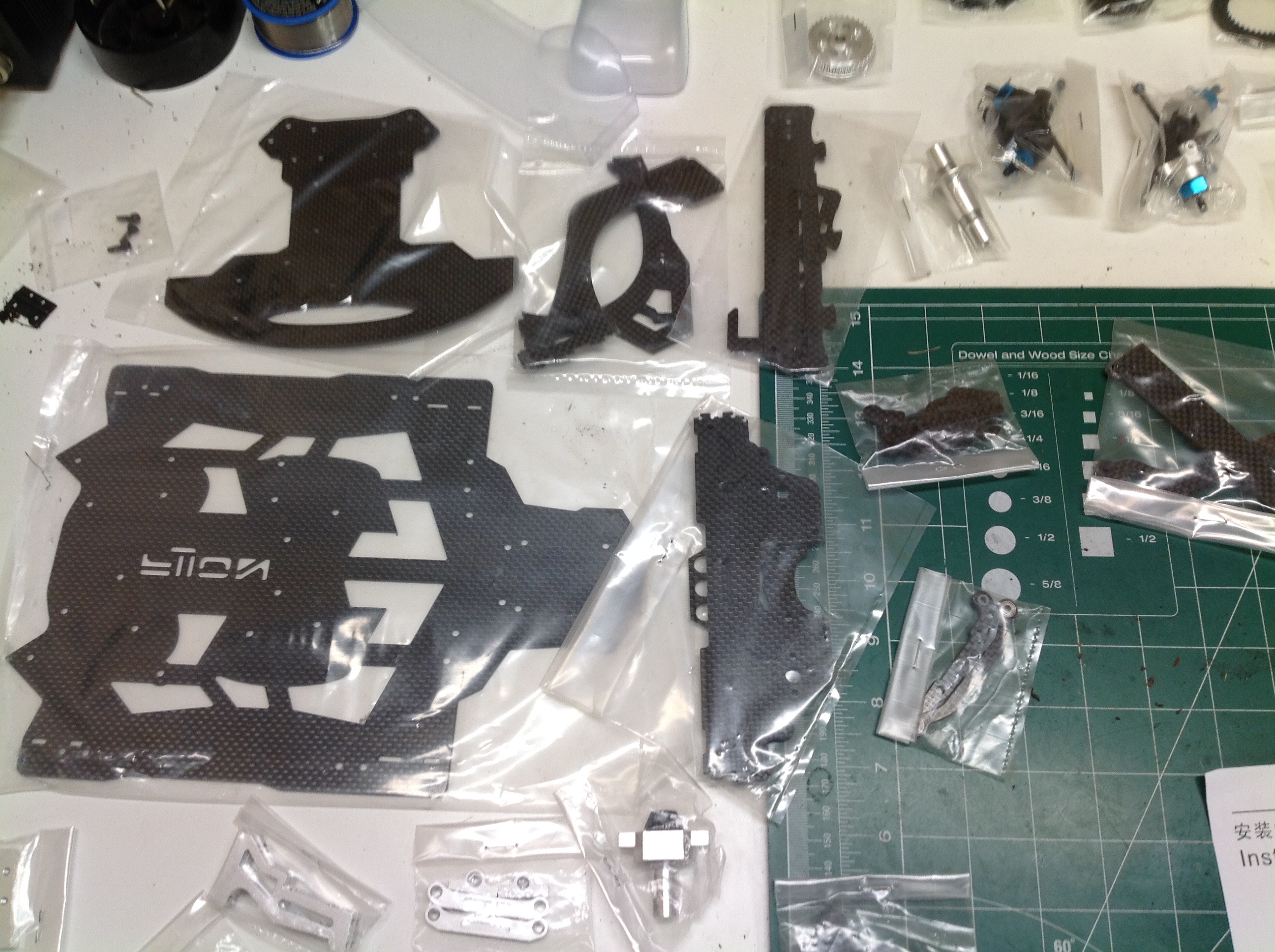
Here you can see some of the glorious parts. On the left are an
unreasonable number of machined aluminum parts, and on the right are a
ridiculous number of laser cut carbon parts. Everything is
carefully bagged. Zoom in and behold the glory.
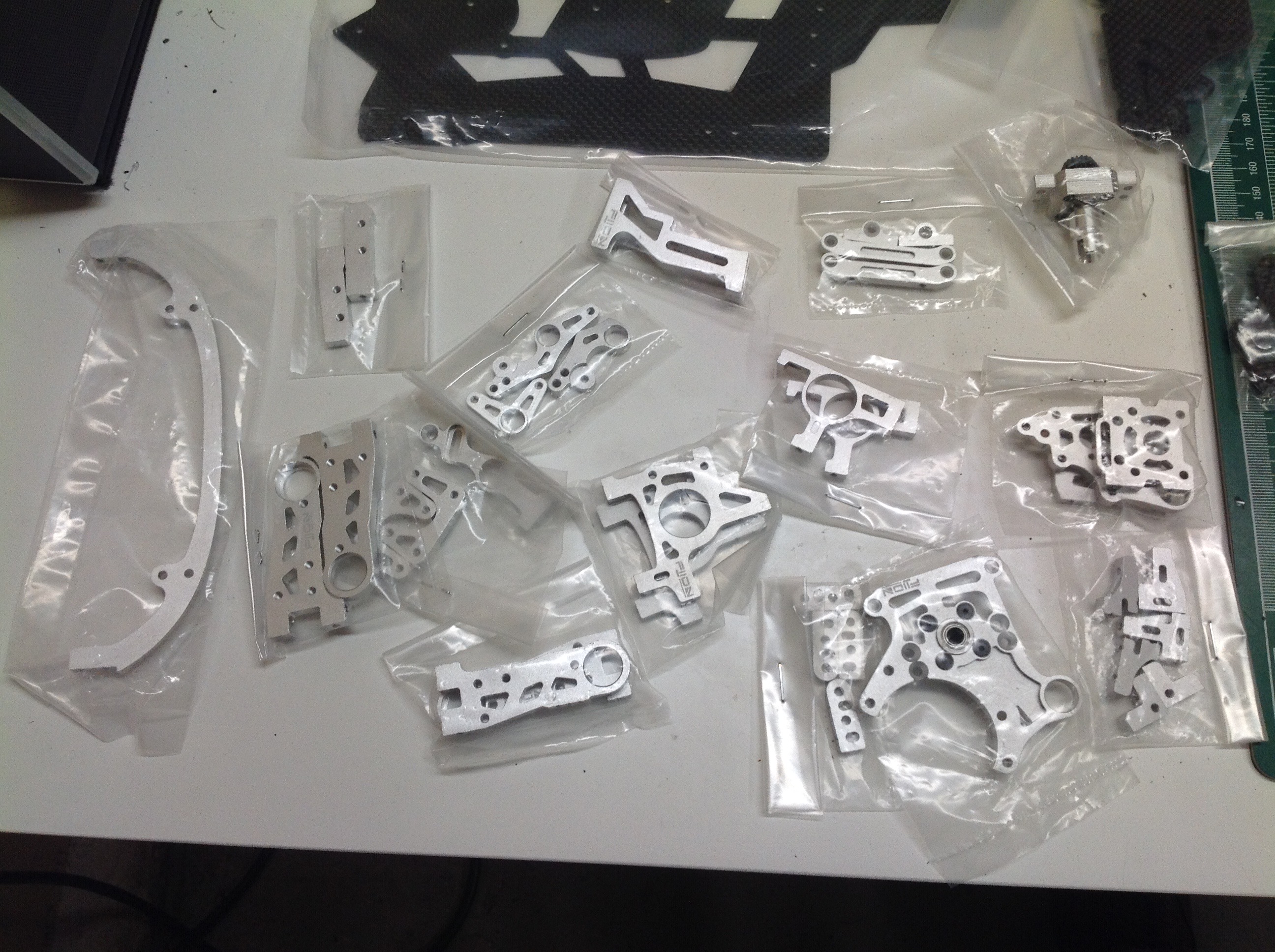
Here are some more detail photos of the hardware and mechanical
parts. Pretty much everything is machined aluminum or steel.
Hardware is divided into seven numbered bags.
The rear shocks are fairly traditional but use a lot of parts as you can
see. Shock body, caps, rod end, and spring perches are all
aluminum.
The front shocks are very unusual for RC but very normal for cars.
These are real MacPherson struts which means that the shock serves
double duty as both a damper and a steering knuckle. The rod turns
within the barrel when the car steers. The upper end has no lug
but instead bolts directly to the chassis with a round plate (like the
real thing)
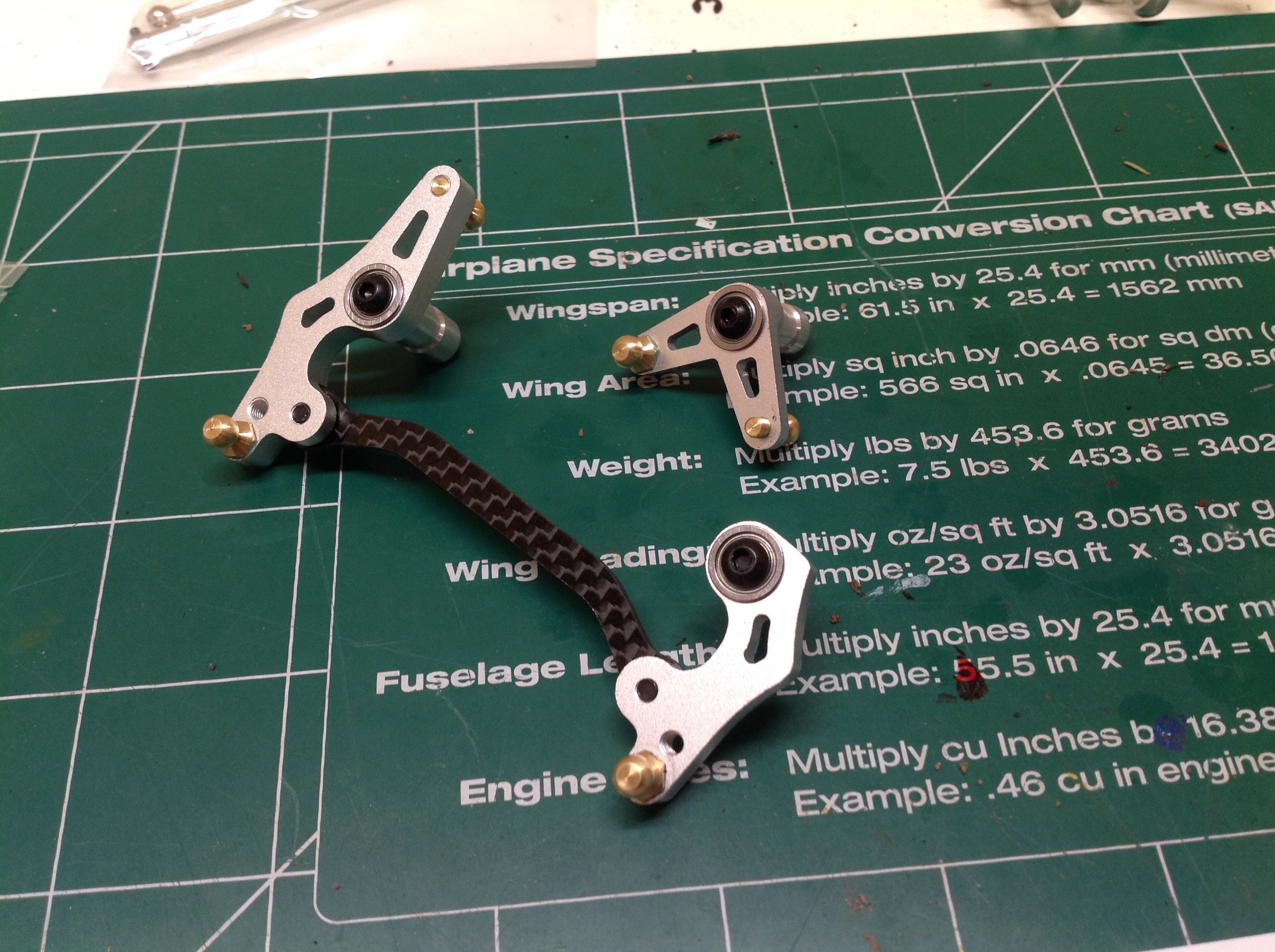
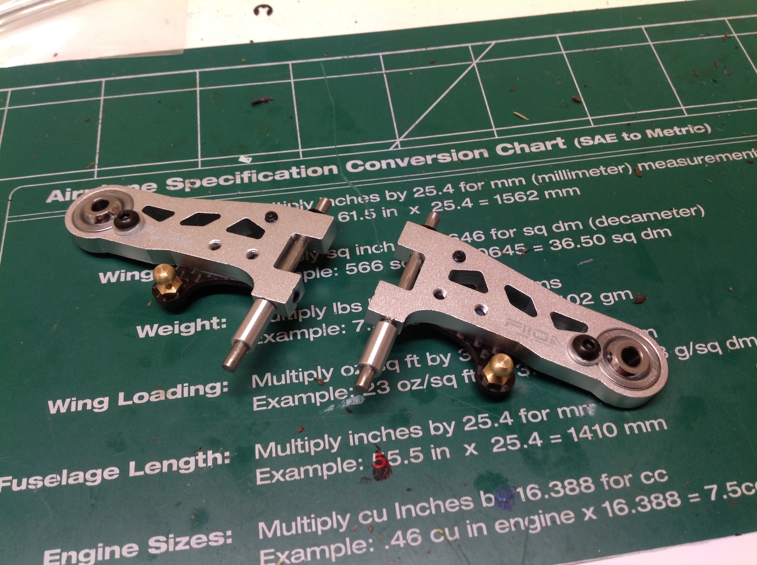
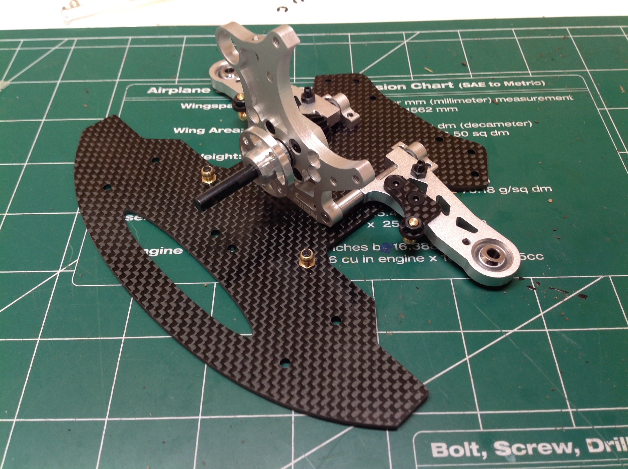
Now we can start the rest of the front suspension. The steering
system uses aluminum dual bellcranks with ball bearings and a carbon
cross member. The lower suspension arms are also machined aluminum
with spherical balls for kingpin joints. The balls on the front
side sit on carbon plates and are for the connection of drag links.
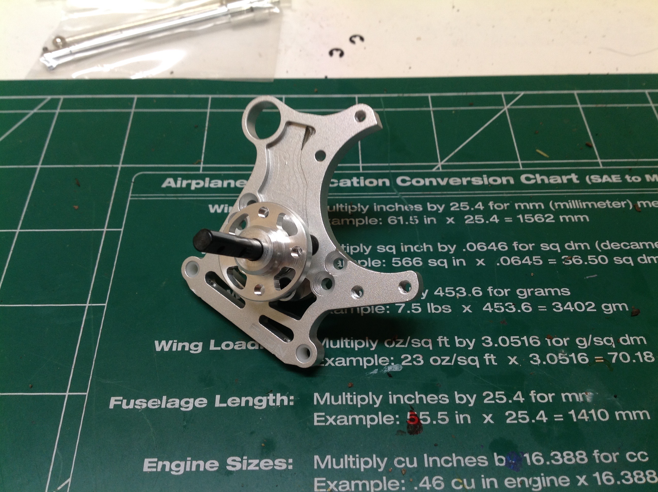
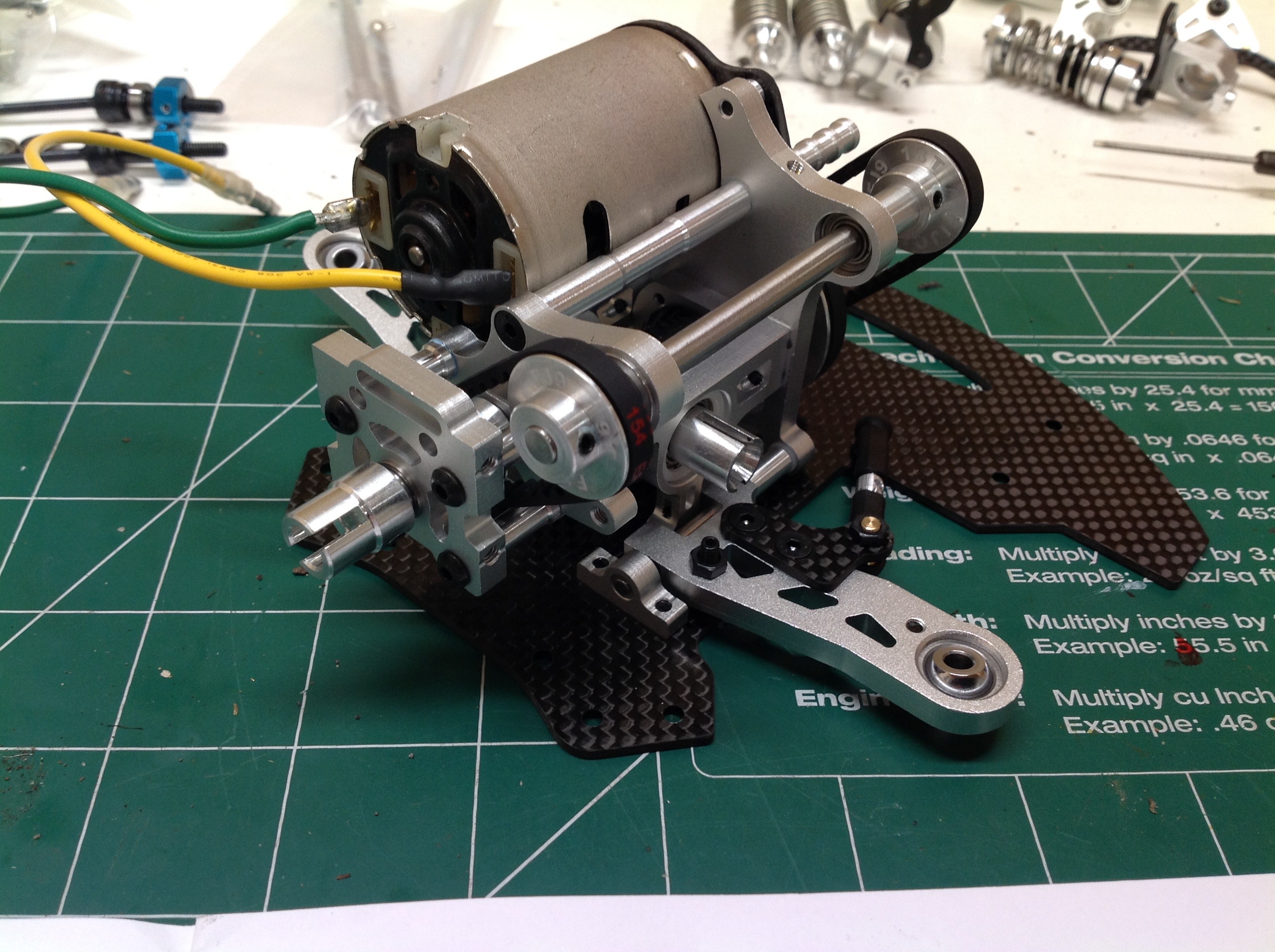
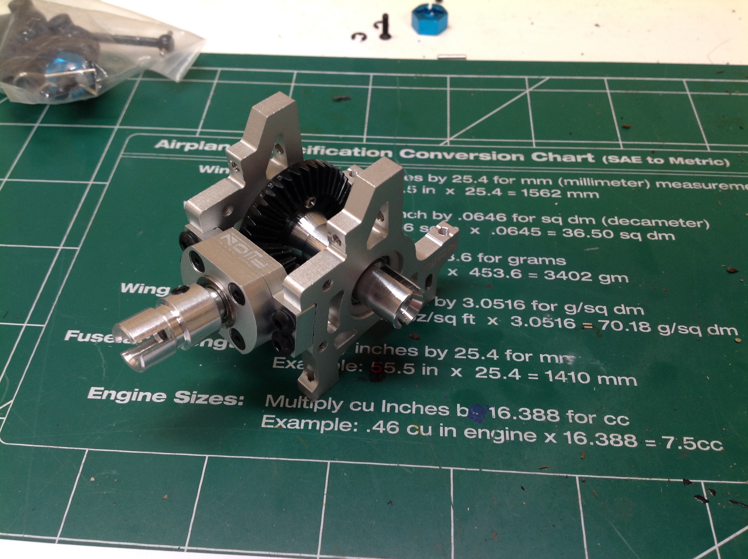
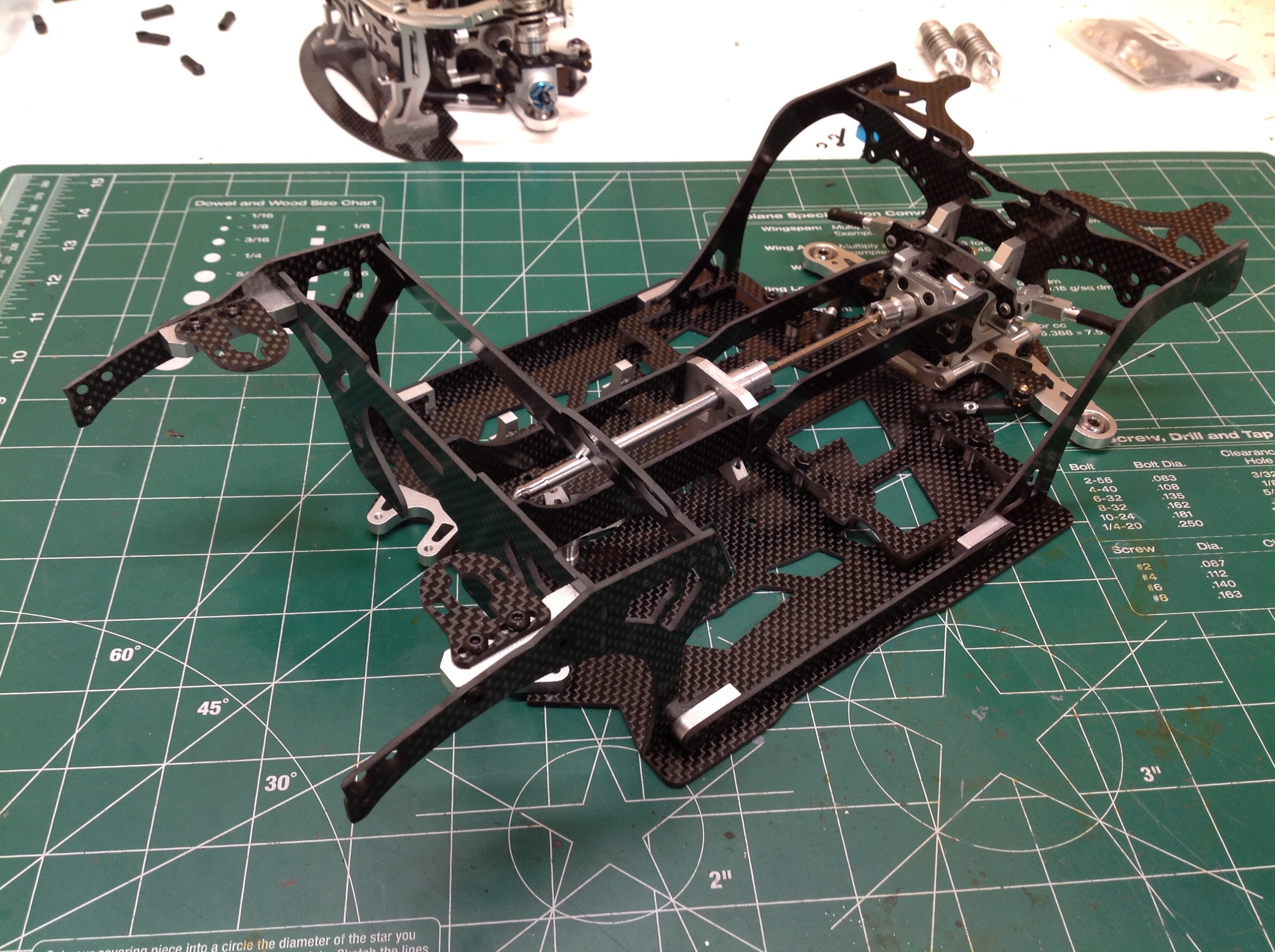
The whole gearbox is located above the front axle and is driven by
belts. We start with what is effectively a flywheel and shaft
attached to the forward bulkhead which then bolts to the front carbon
chassis plate. This plate incorporates the front bumper. The
bulkhead supports the front end of the lower suspension arms, and the
rear ends are supported by pillow blocks. The rear side of the
flywheel shaft has the pinion gear for the front ring gear.
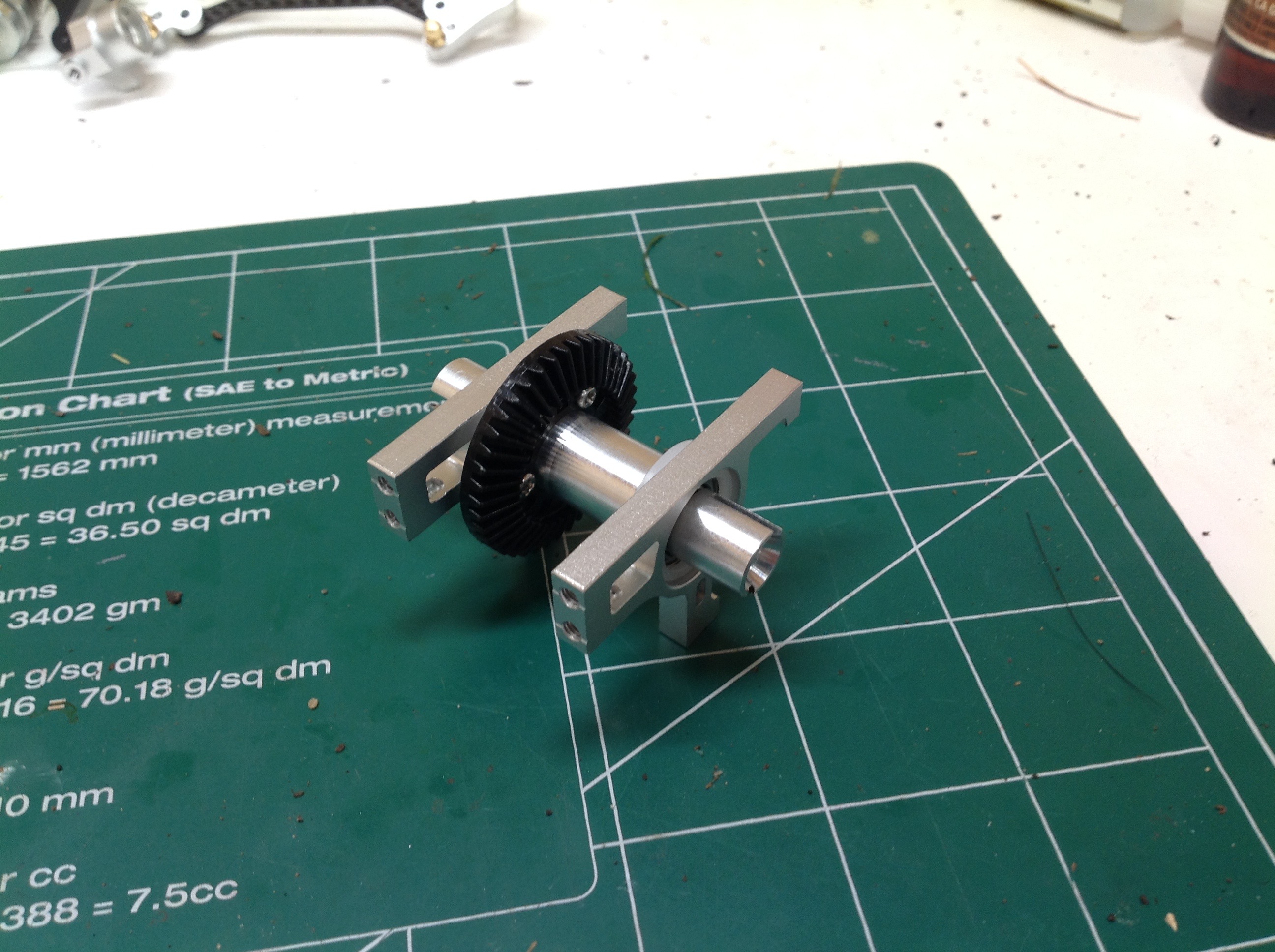
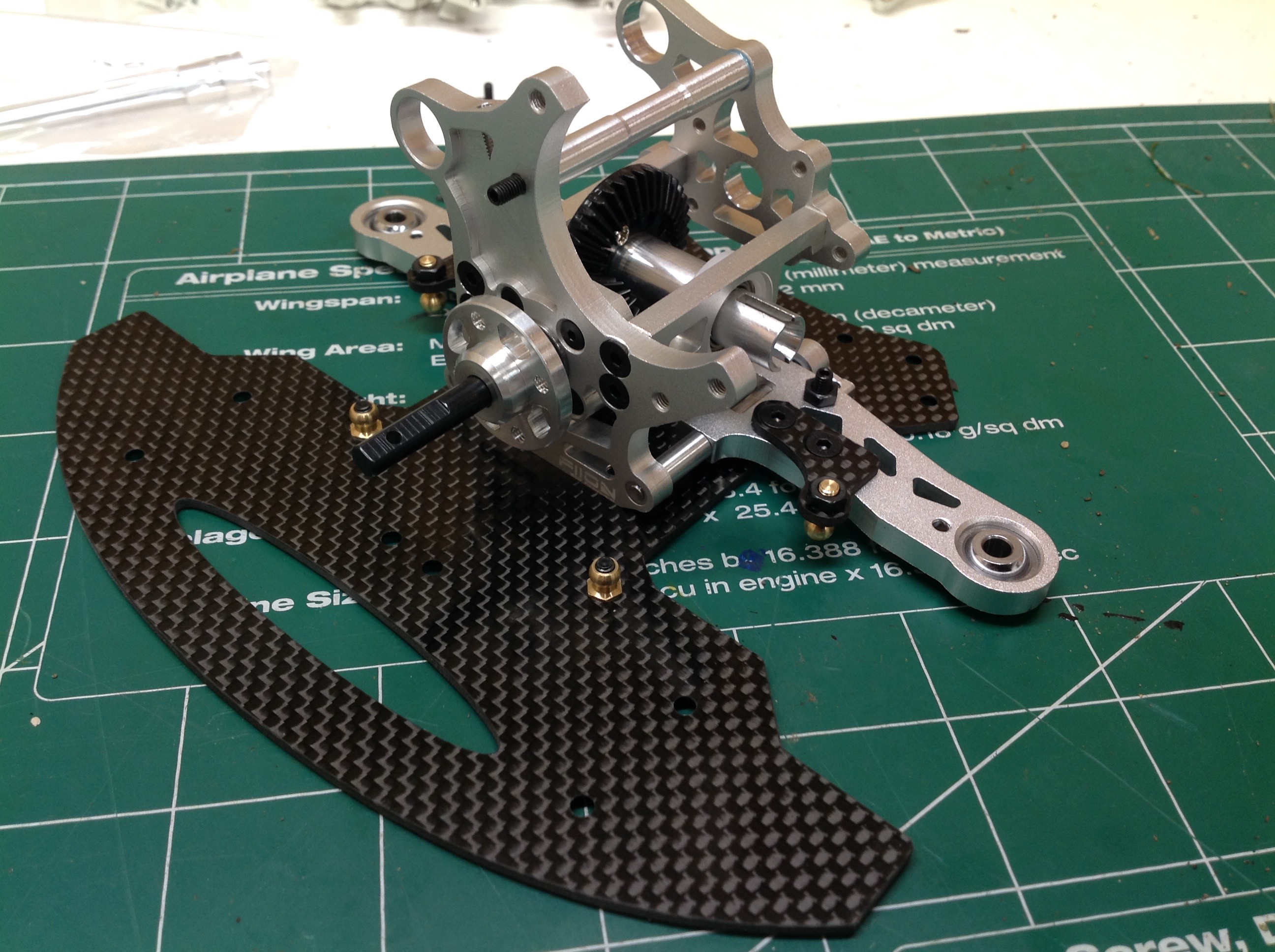
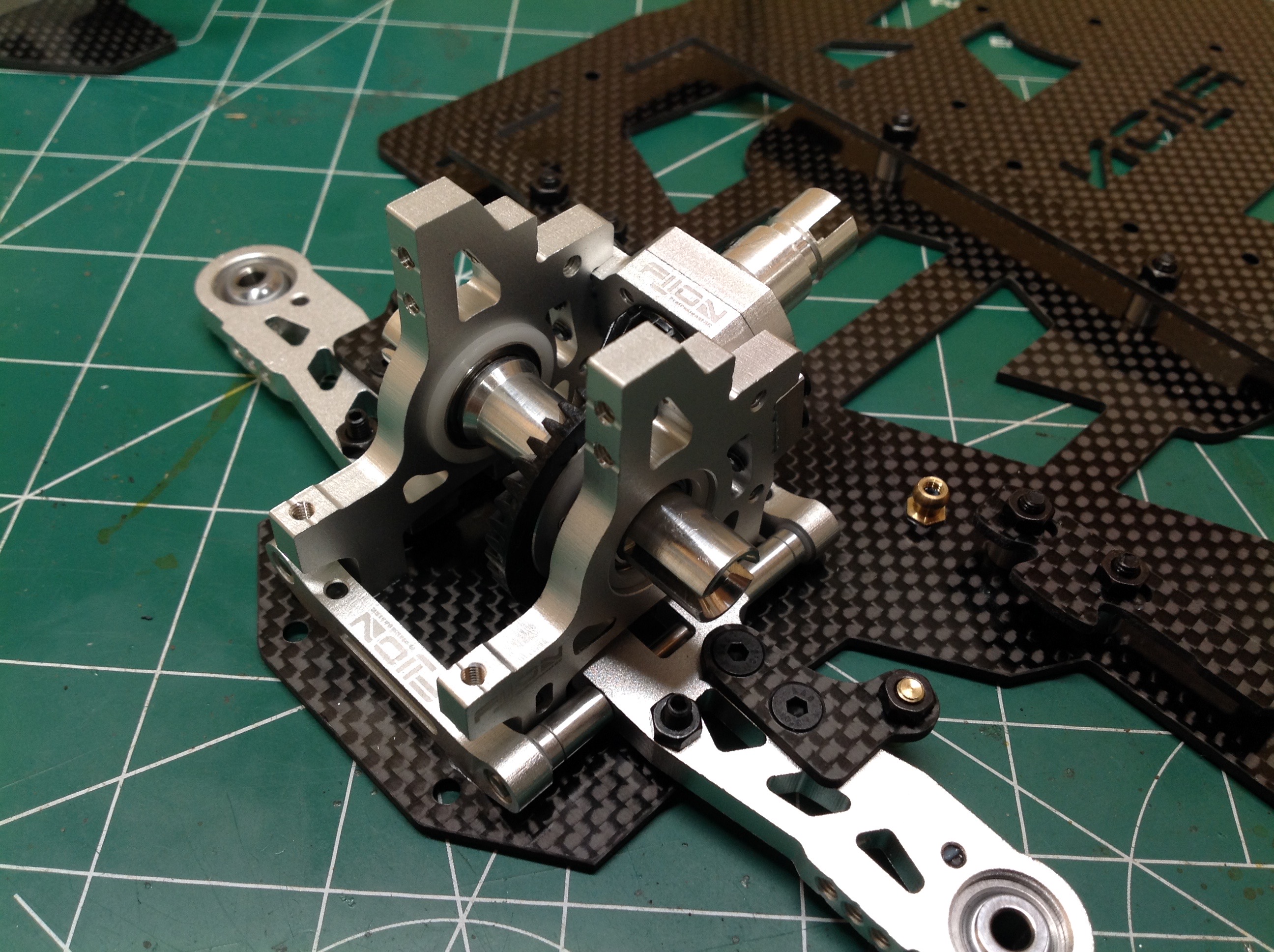
Oddly enough, the only plastic parts on the model are the gears.
There is no differential so this ring gear just drives a locked spool
supported by ball bearings. The support blocks span the front axle
and support the rear half of the front bulkhead.
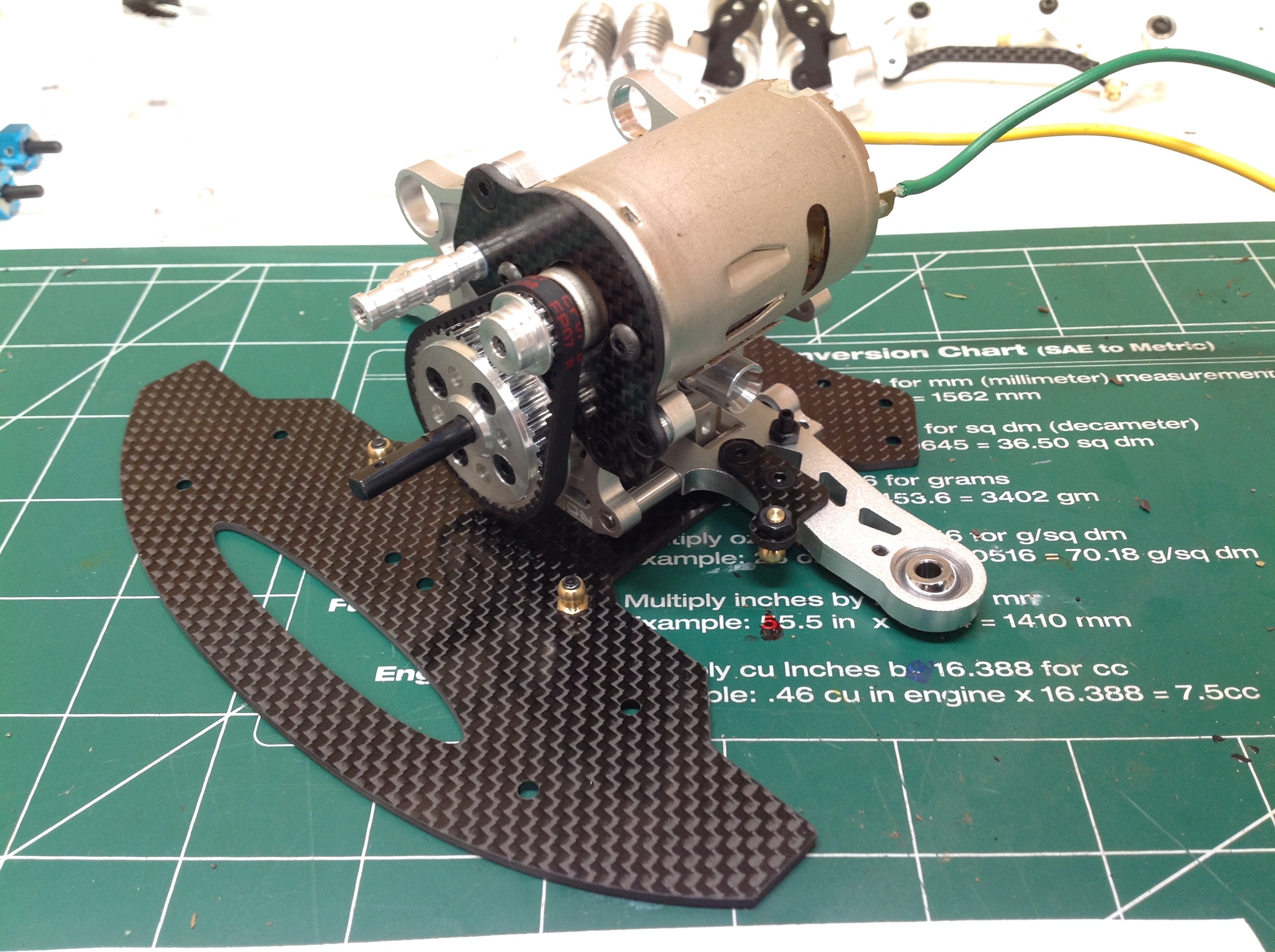
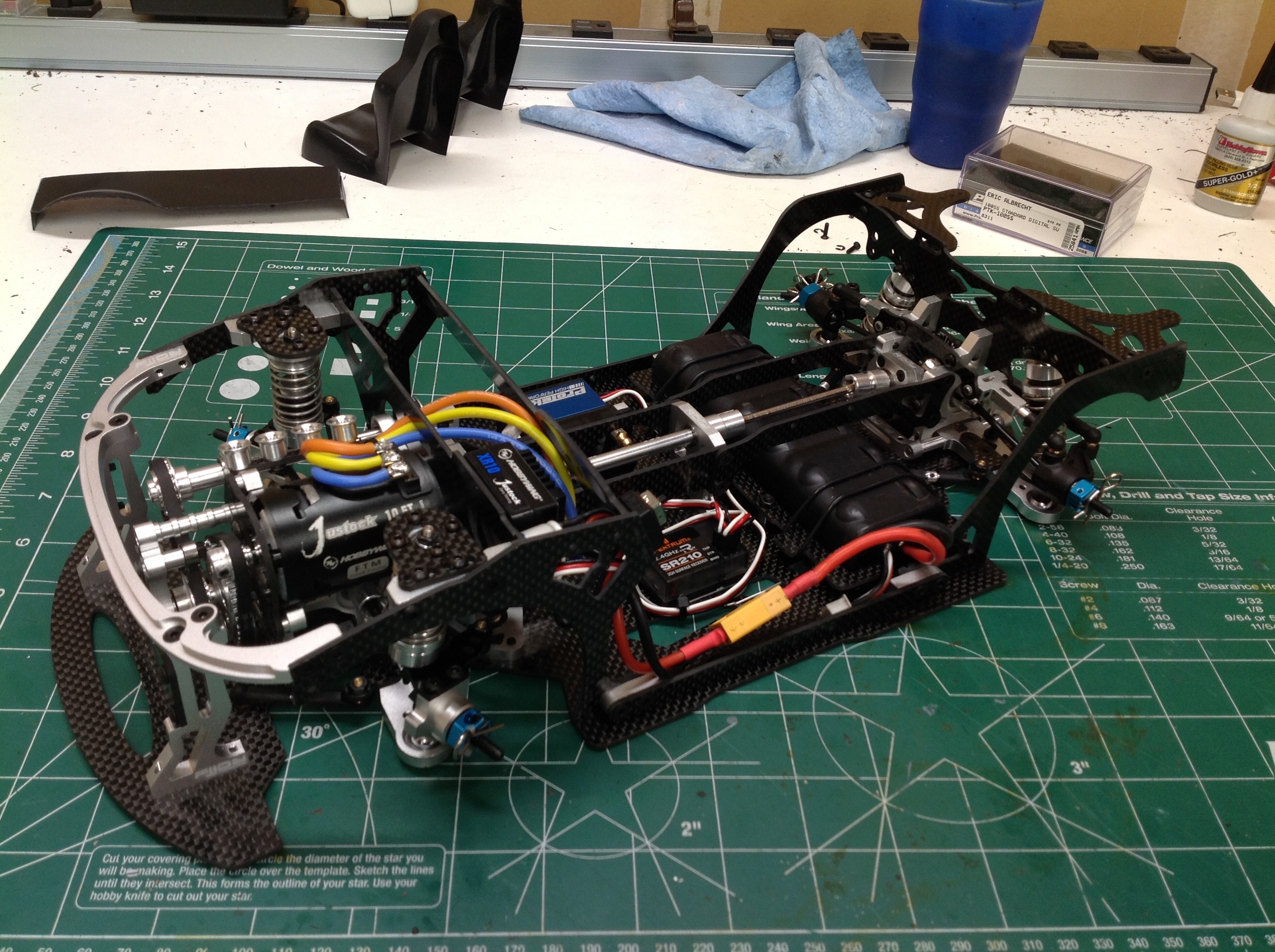
These pictures show the temporary motor I installed while waiting to
decide on a power system. There is no motor pinion, instead the
motor shaft support a small pulley. This pulley drives the large
pulley which goes right to the front wheels. The second smaller
belt will end up driving the rear axle.
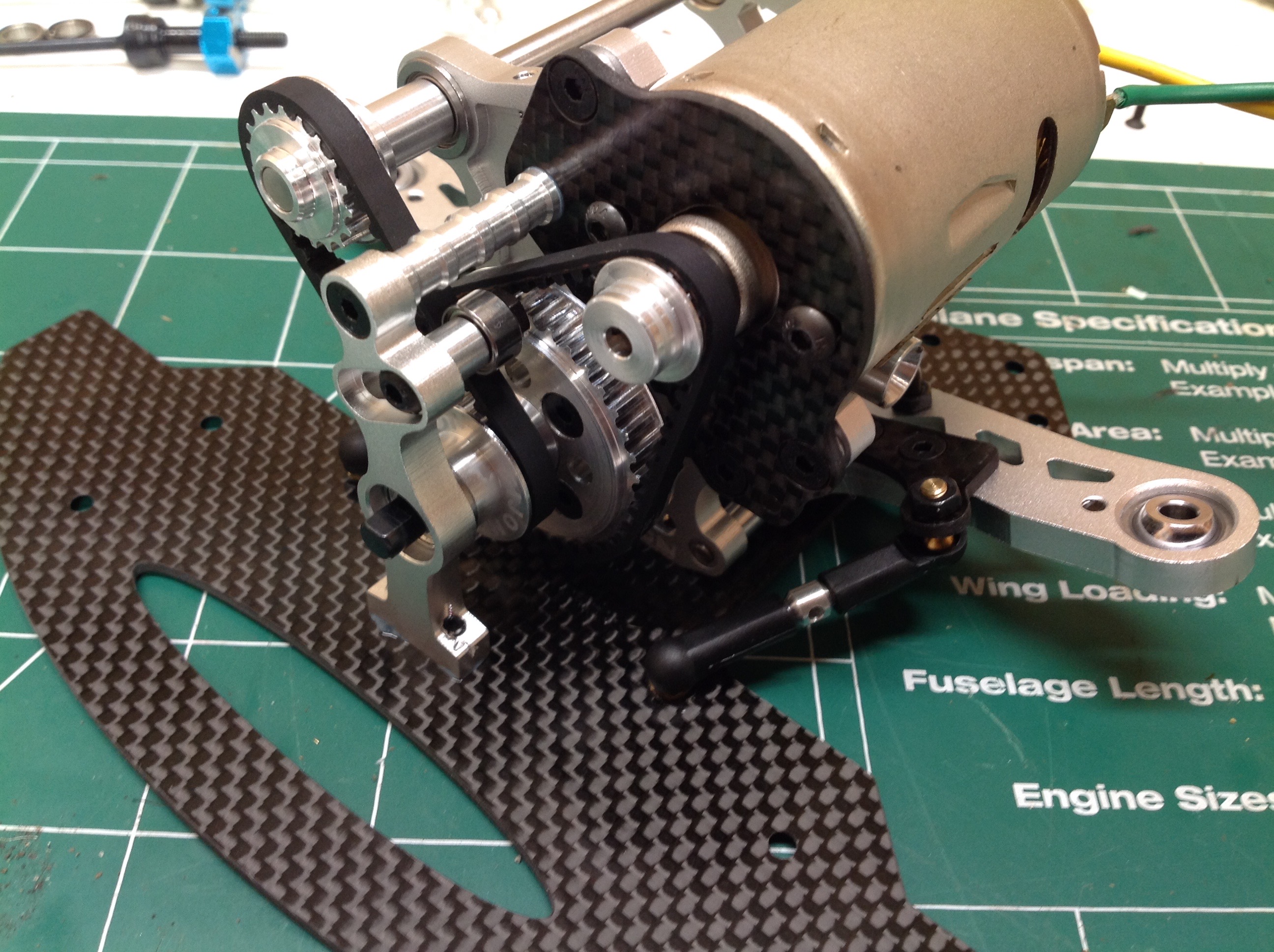
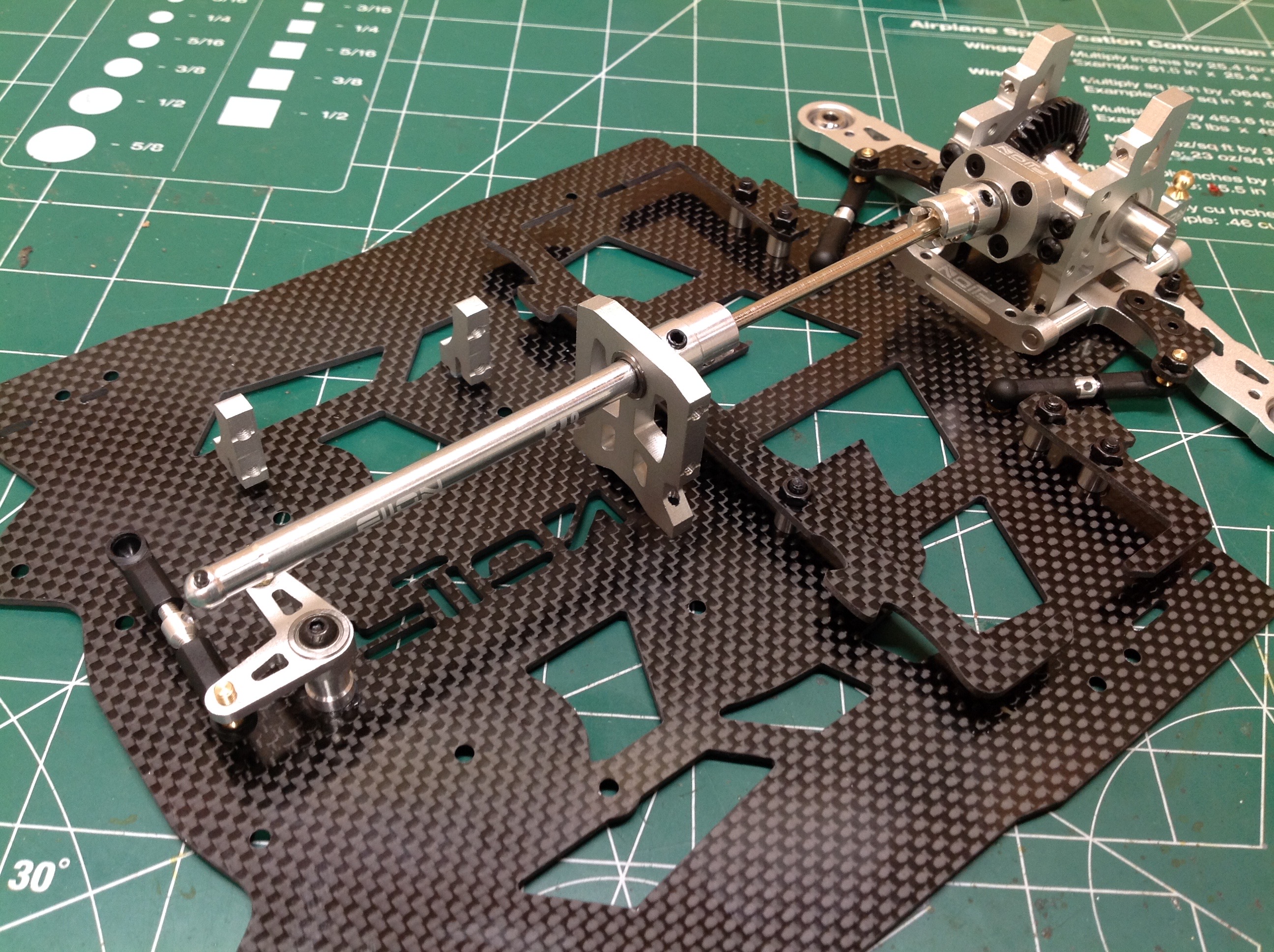
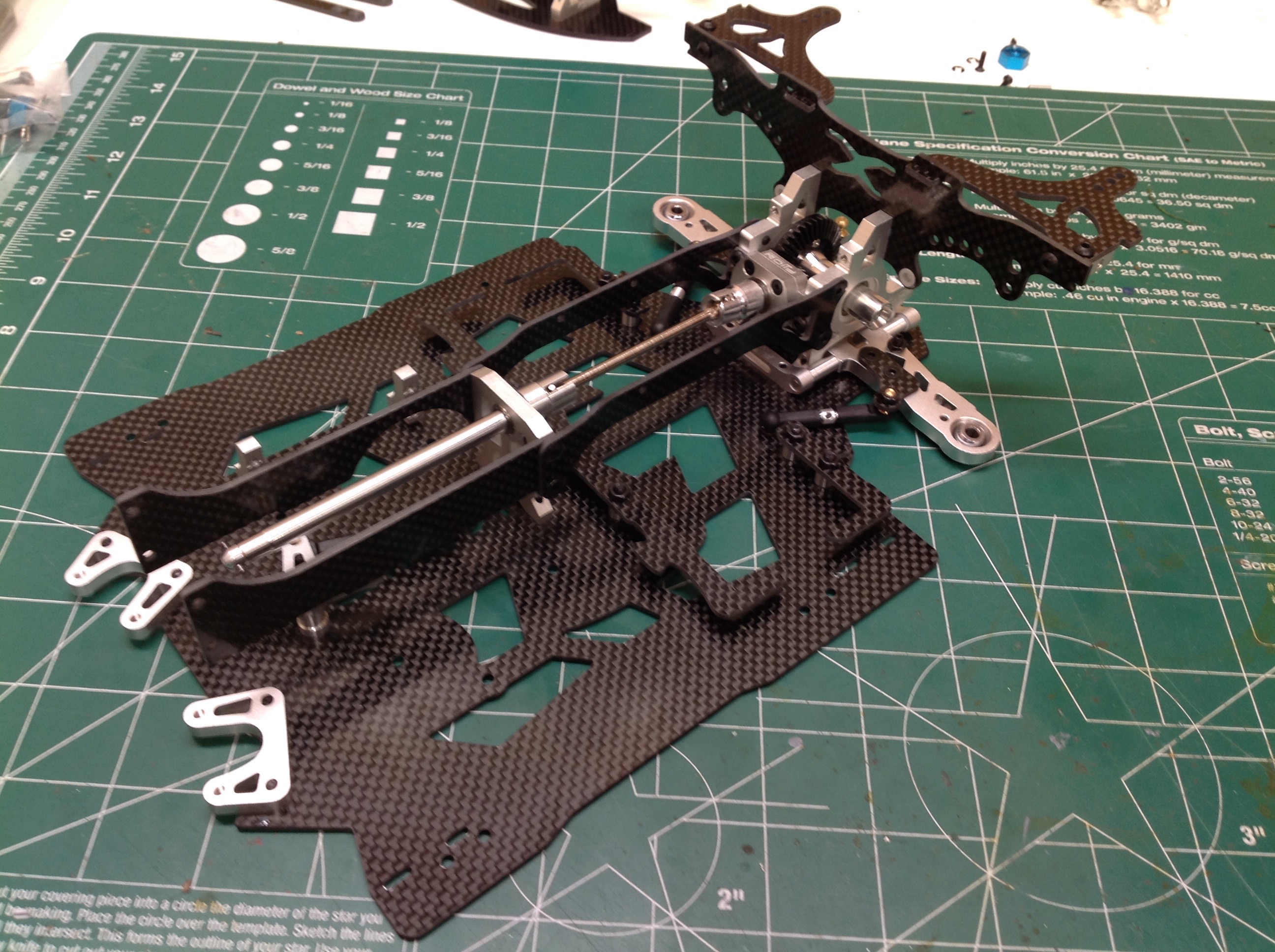
Behind the motor we see another belt which transfers power back down to
the car centerline for the prop shaft which will go to the rear
wheels. It might appear to have two identical pulleys, but they
actually have a
1.3:1 ratio and therefore send 30% overdrive to the rear axle.
Those belts are tight and put a lot of side load on that axle so it is
important the axle be supported at both ends. On the right you can
see the front support as well as the drag links attached to the lower
suspension arms. You can also see a small bearing which acts as a
belt tensioner.
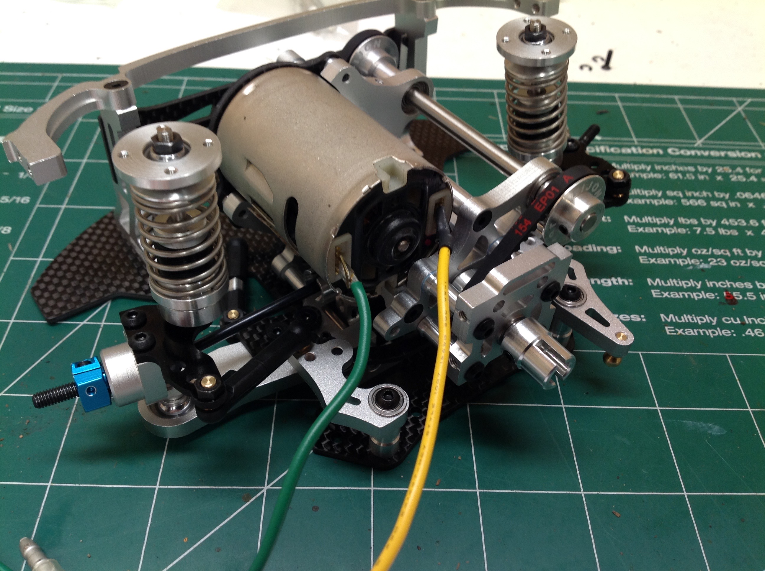
There's probably no reason this front fascia support needs to be
aluminum, but I'm OK with it. It will indirectly be supporting the
top ends of the front shocks. Remember, there are no upper
suspension arms with a Macpherson Strut suspension, but the steering
links and knuckles have been added.
I chose a 10.5T Hobbywing brushless motor for this car, but the
available space was so tight than I had to mill away a pocket in the
rear closure to get it to fit. Once installed, you can hardly tell
I changed anything. The belt drive system has quite a bit of drag
so it takes some non-trivial throttle to get things spinning even
without wheels attached.
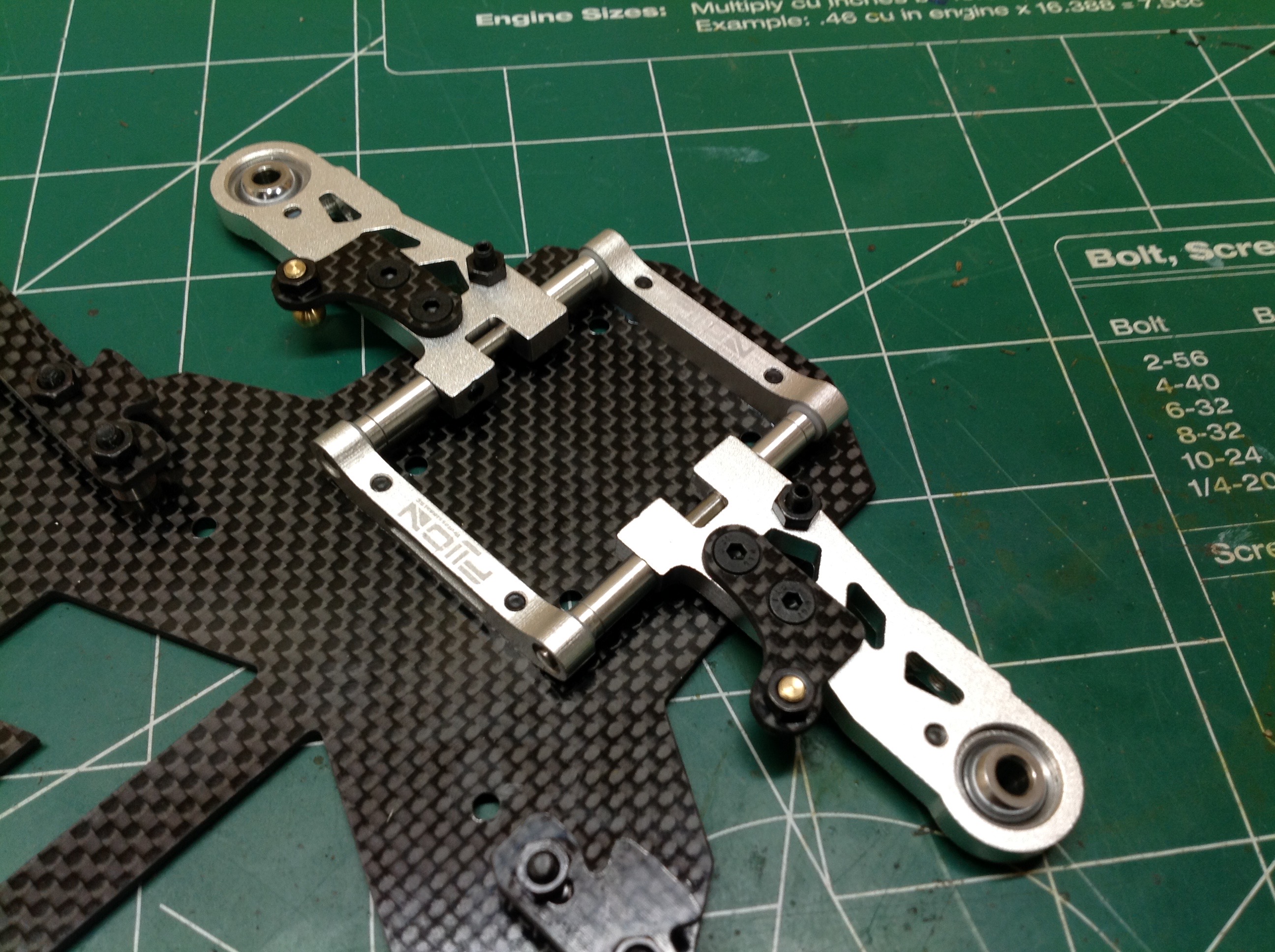
The rear carbon chassis plate is huge. It's the single largest bit of RC
carbon fiber plate I've ever seen. It is so choice. The
guards you see toward the back are the supports for the transverse
mounted battery. The battery is a standard stick pack size, so
that shows you how wide the plate is. The aluminum bit is a lower
suspension arm support.
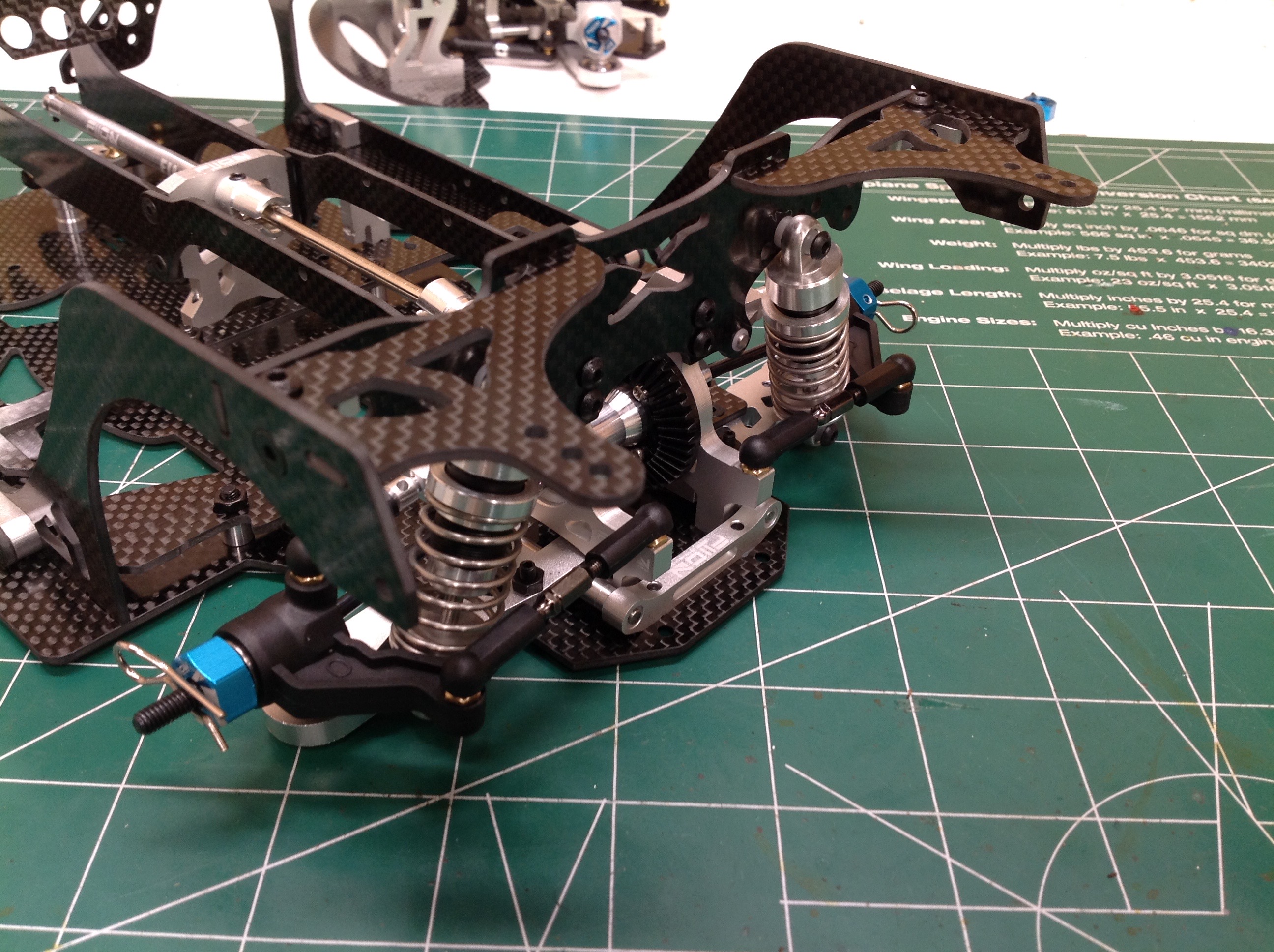
The rear lower arms look much like the front with the spherical ball
joints and carbon drag link plates. There is no toe angle on the
hinge line.
The rear spool is enclosed in a box which incorporates a slight incline
on the drive cup. Like the front, this is a locked spool with no
differential.
Here you can see the incline on the rear prop shaft which allows it to
pass over the battery tray. Two vertical carbon plates are then
installed to form a chassis center channel. You can also see the
carbon shock and body supports in the rear.
Now the rear upper suspension arms have been installed. The length
of these can be adjusted to vary camber angle. The rear drag
links have also been installed.
Now that's a lot of carbon. Even the wheel arches are carbon
fiber. This is also the point at which the rear wheel hubs and
shocks are installed as shown on the right.
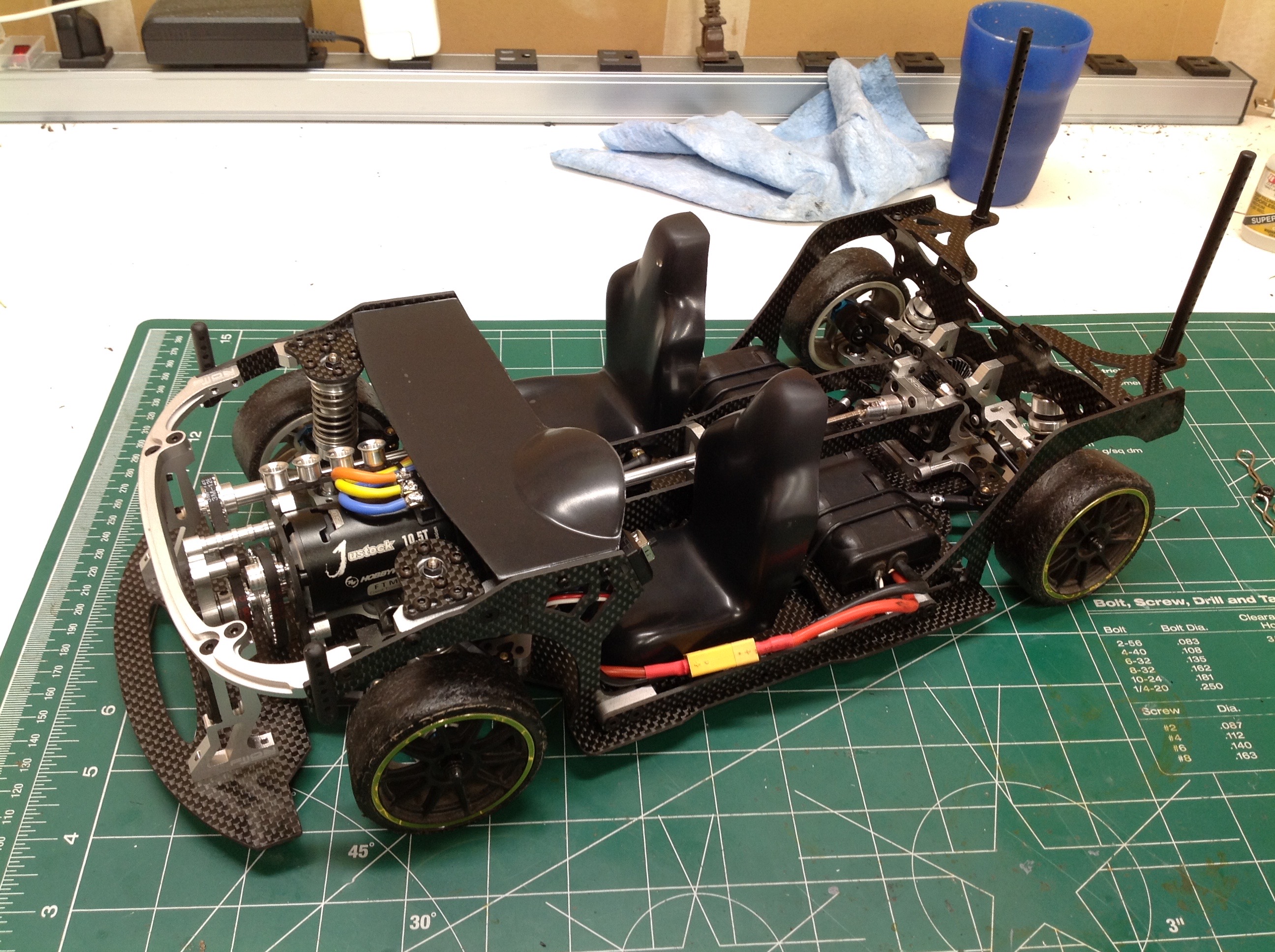
Finally the front and rear halves of the chassis can be connected
together. To complete the chassis a pair of seats and dash board
are installed. These are transparent polycarbonate parts which I
painted black. The kit did not come with wheels or tires so I used
some that I had from another car as a start.
This part is the only one that caused me a problem during
assembly. This is a clamping 12mm drive hex, but the clamping face
was so thin that it deformed instead of clamping. I had to
replace it.
©2019 Eric Albrecht