Tamiya TRF 414X Project
Page 2: Assembling the Chassis
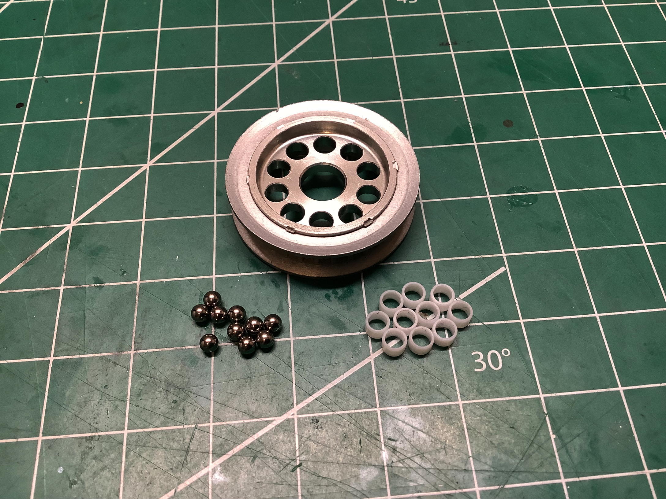
There are no traditional "steps" in the manual, but the first exploded
view shown is of the ball differential. The ball diff uses ten 3mm
hard tungsten balls arranged in an aluminum hub which doubles as a
pulley. To avoid having the metal balls ride directly on the metal
hub, each ball sits in a cylindrical Delrin insert. The pressure
plates are hardened steel supported by mild steel drive cups. The
thrust bearing is a swaged unit that doesn't need to be assembled.
The manual says nothing about grease so you just have to be smart
enough to know you need some.
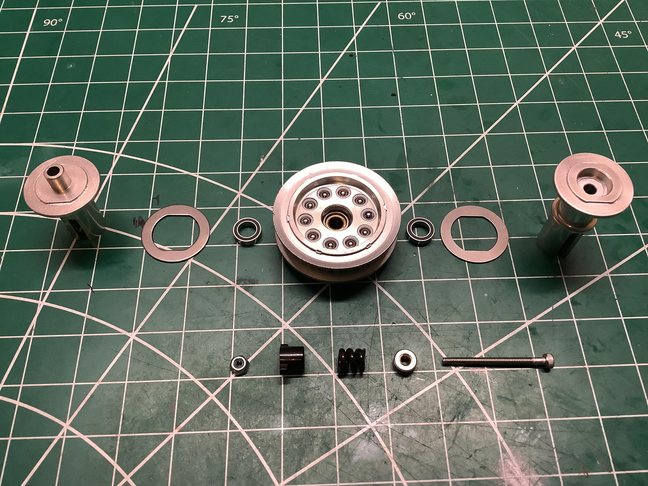
The regular TRF 414X kit came with a front one-way, but also included
parts for an optional front ball differential identical to that used in
the rear. Since my version came built, I do not have the second
optional ball differential. The pictures above show the parts for
the front one way which is built into the front aluminum pulley.
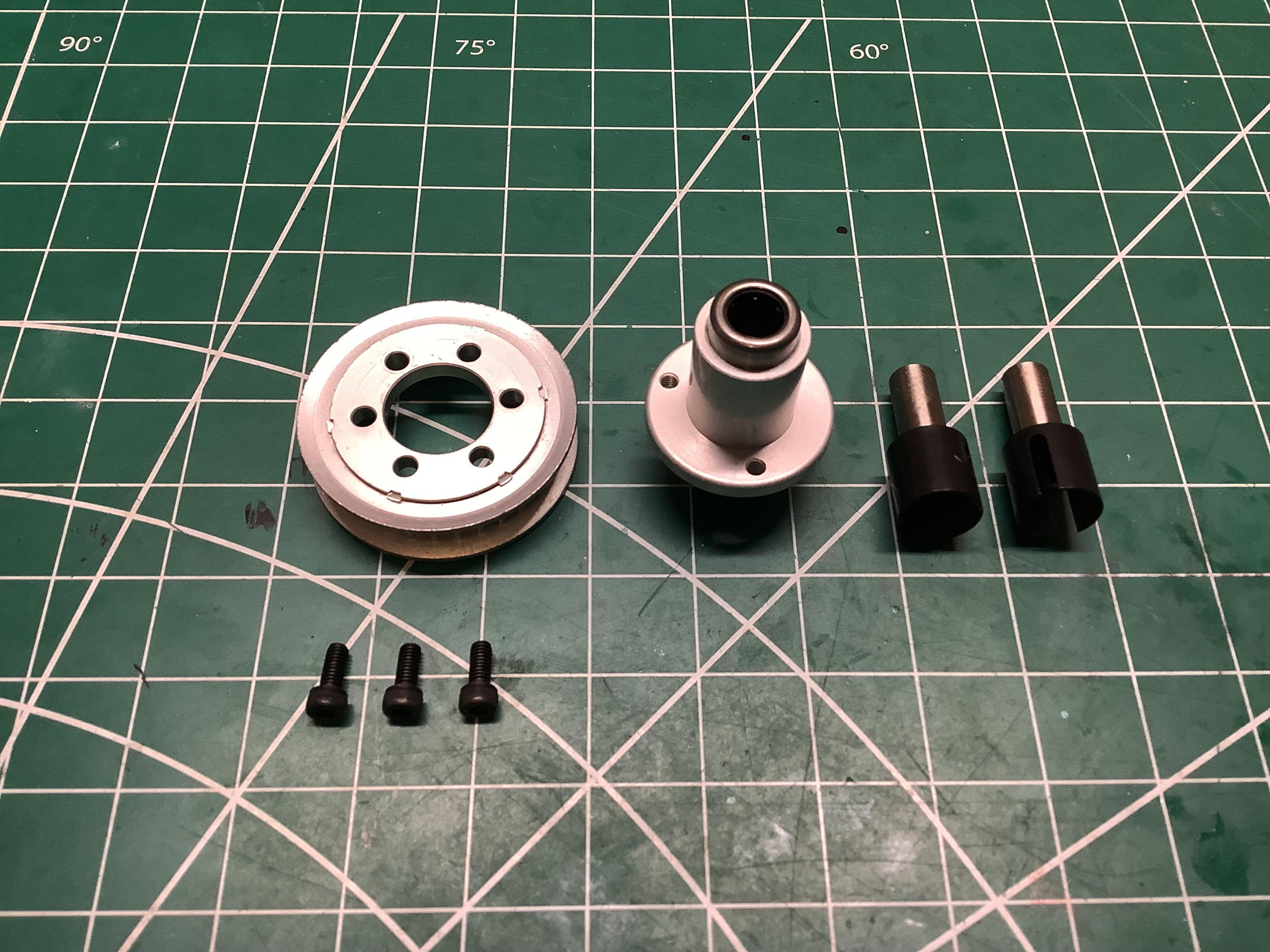
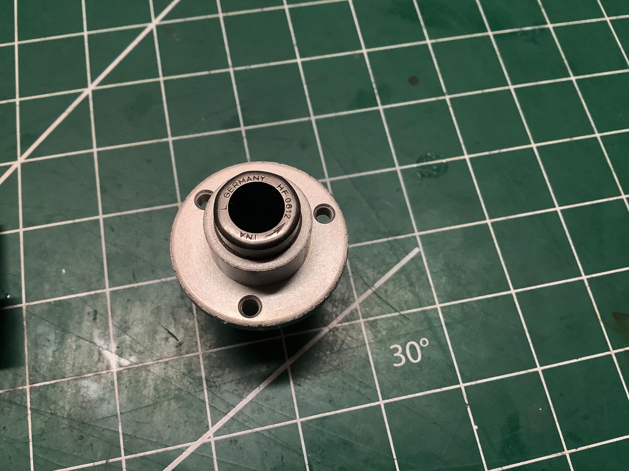
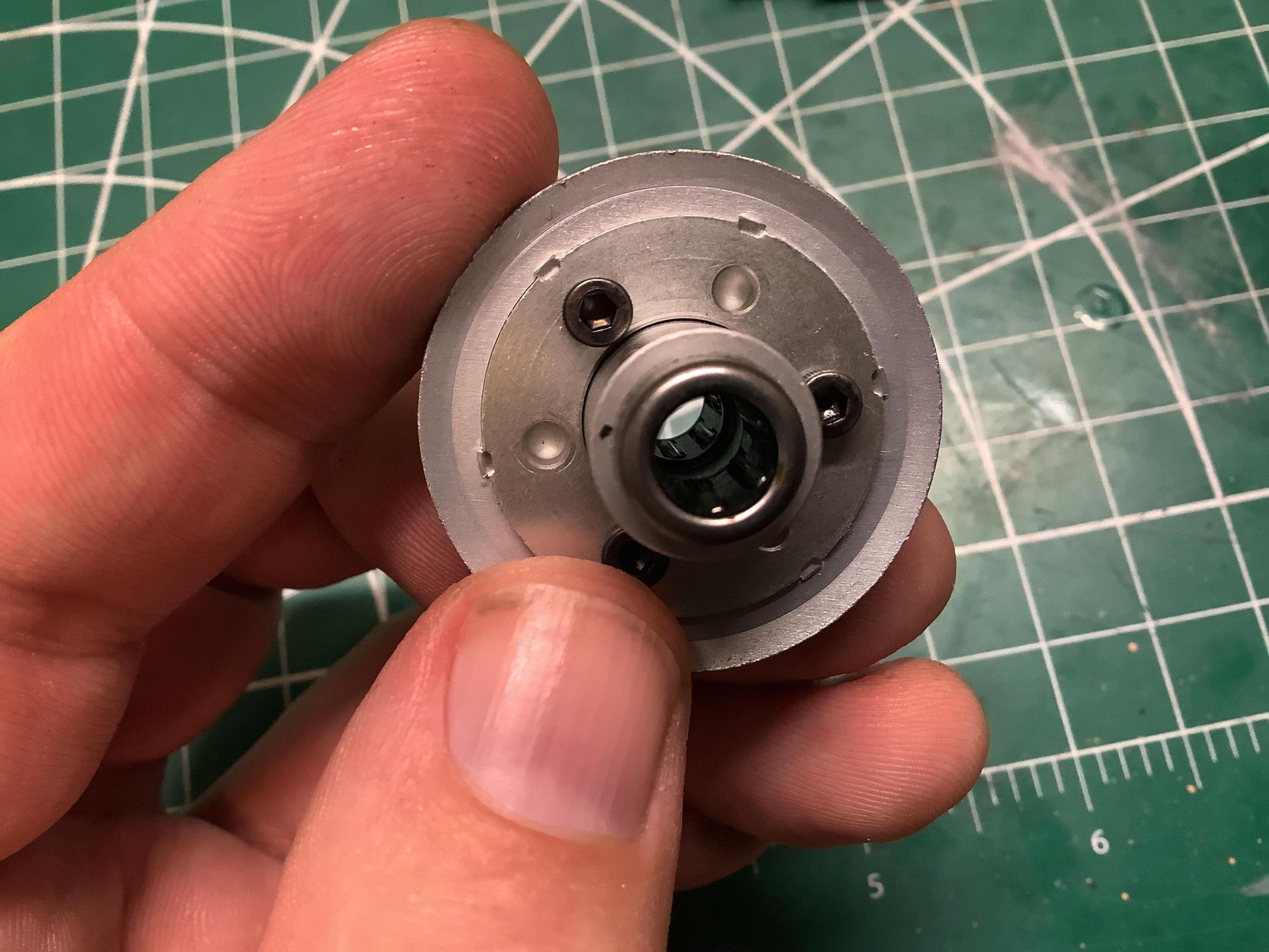
If you zoom in on the photo on the right you can see that the one-way
bearing part itself is from INA in Germany, uses a 6mm bore, and is
pressed into an aluminum hub. There are actually two of these
bearings, one pressed in from either side. This allows the left
and right drive cups to spin at different rates in corners, simulating a
differential.
Ever wonder how a one-way bearing actually works? You'll need to
zoom in on the full size photo to follow me on this one. The
cylindrical needle rollers sit in an asymmetric slot. In one
direction they can roll freely, but in the other direction they are
forced into a hardened tang which bites into the rollers and causes them
to jam against the mating shaft. Please ignore the hand model I
hired for this photo.
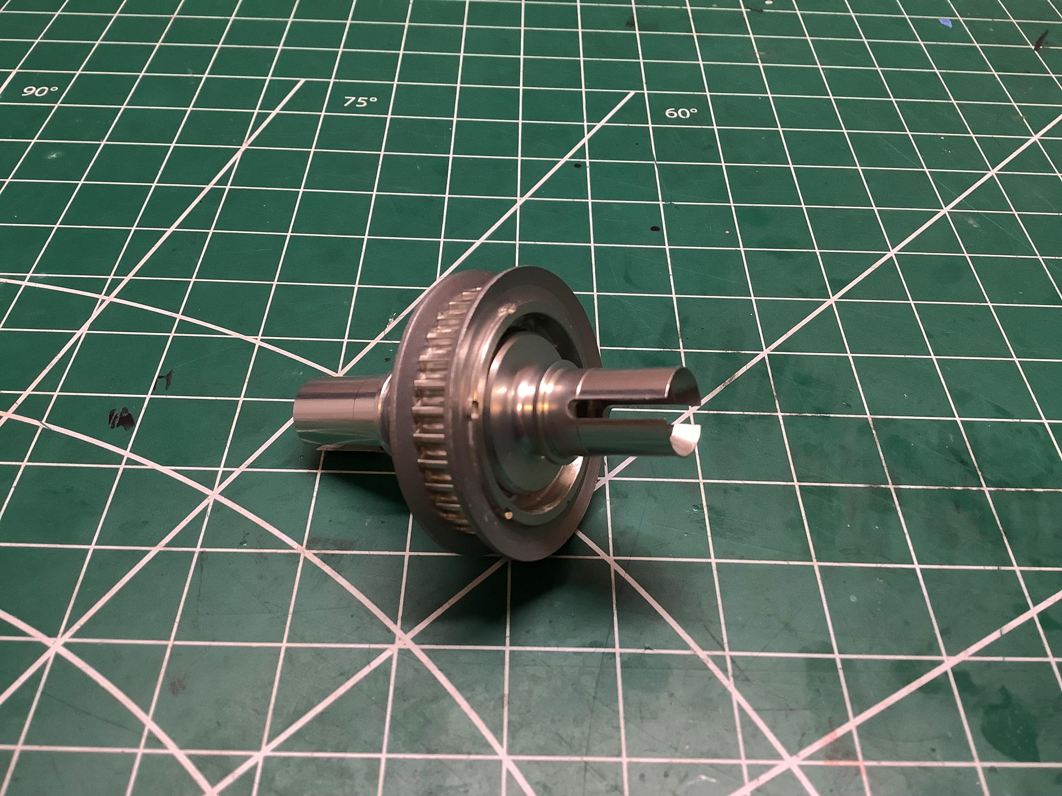
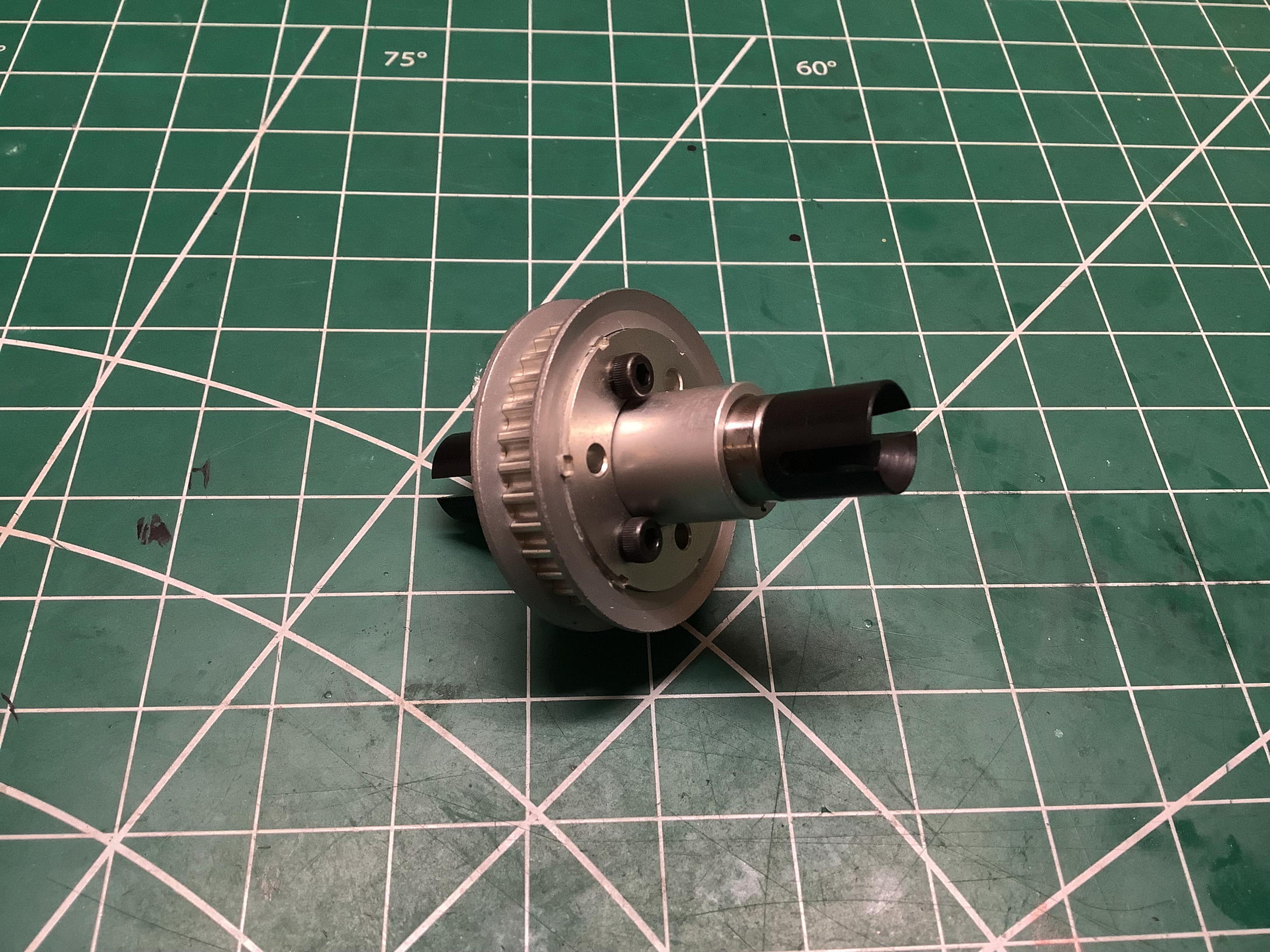
Here are photos of the completed ball differential (left) and front
one-way (right). They look pretty similar and both use 32T pulleys
but you don't want to get them mixed up. It's also really
important not to install the front pulley backward or the front wheels
won't be driven.
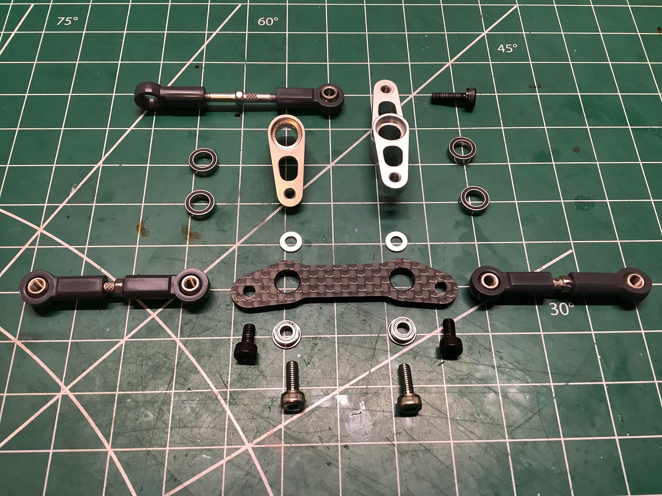
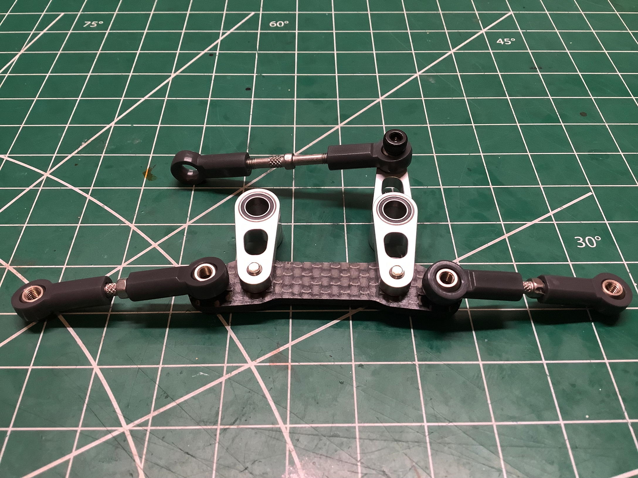
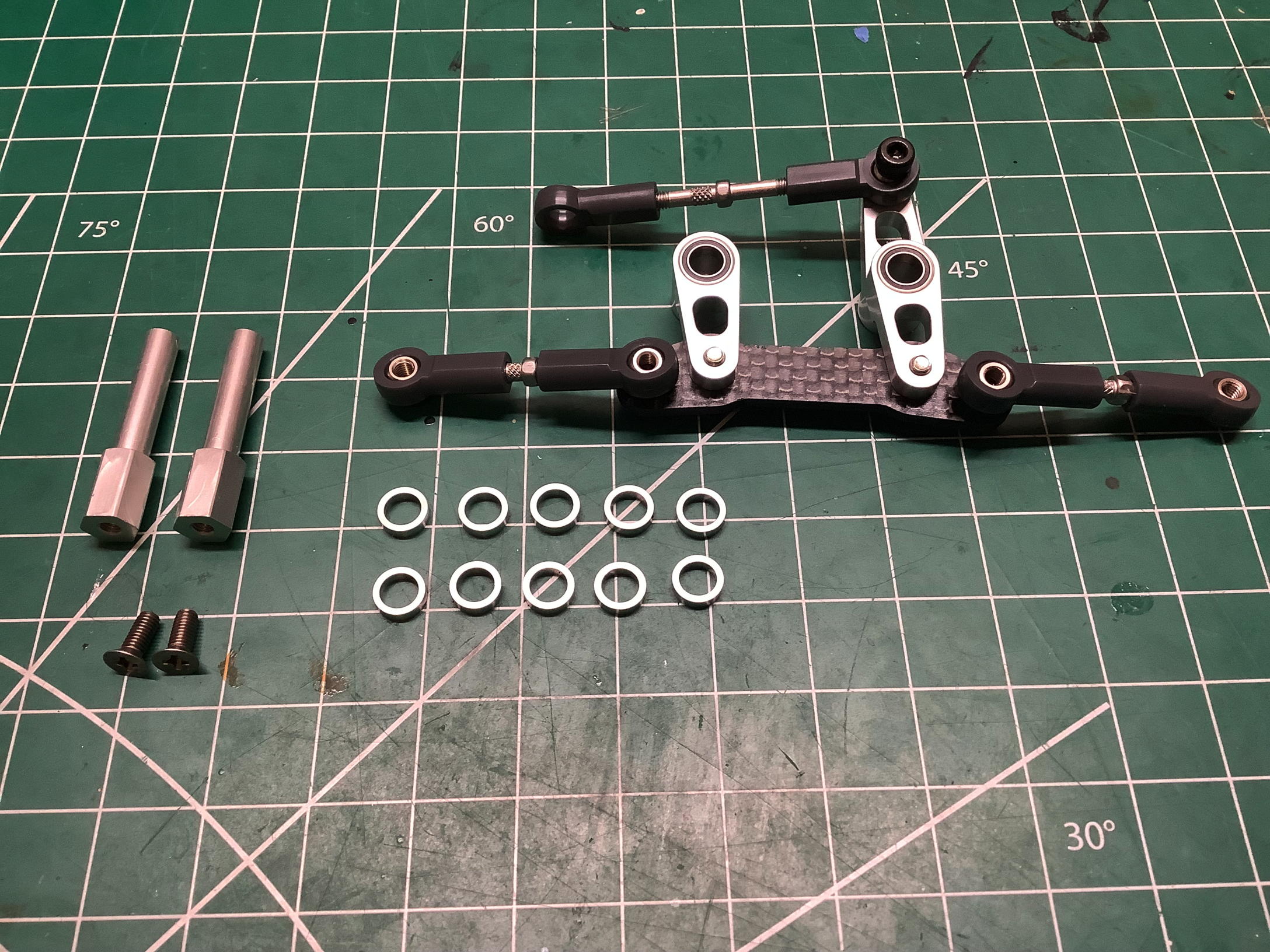
The dual bellcrank steering is designed for precision. The
steering bridge is a carbon fiber plate with flanged bearing
inserts The use of 0.7mm spacers makes the aluminum cranks clamp
very slightly (0.2mm) proud of the bridge surface so they don't jam
against it. The cranks ride on dual ball bearings.
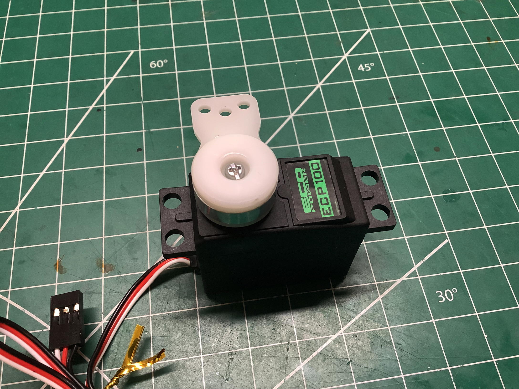
The model uses a high torque servo saver with a white Delrin servo
horn. I don't plan to drive this model, but I did want to put a
simple servo in place to at least hold the wheels in the right position.
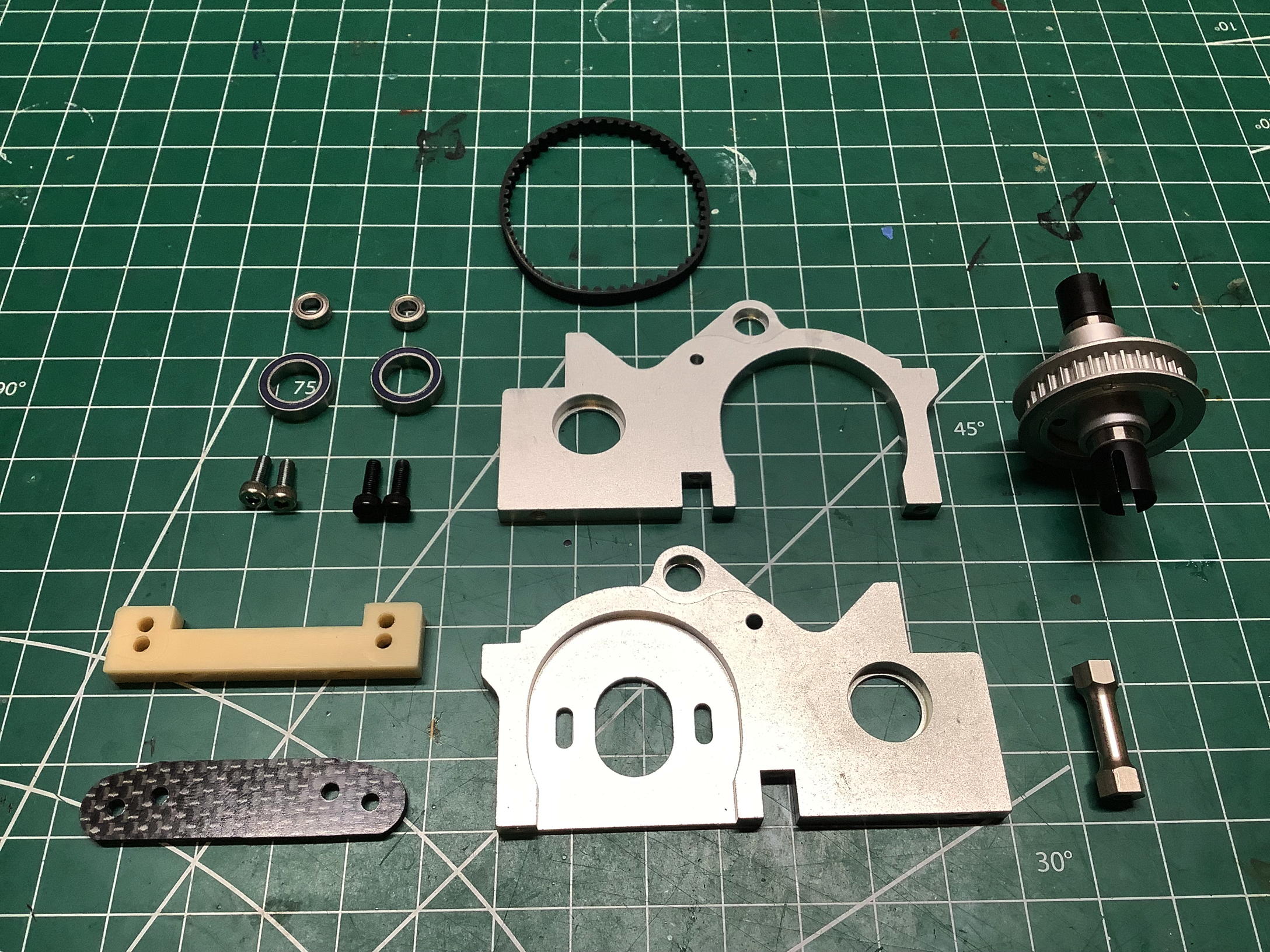
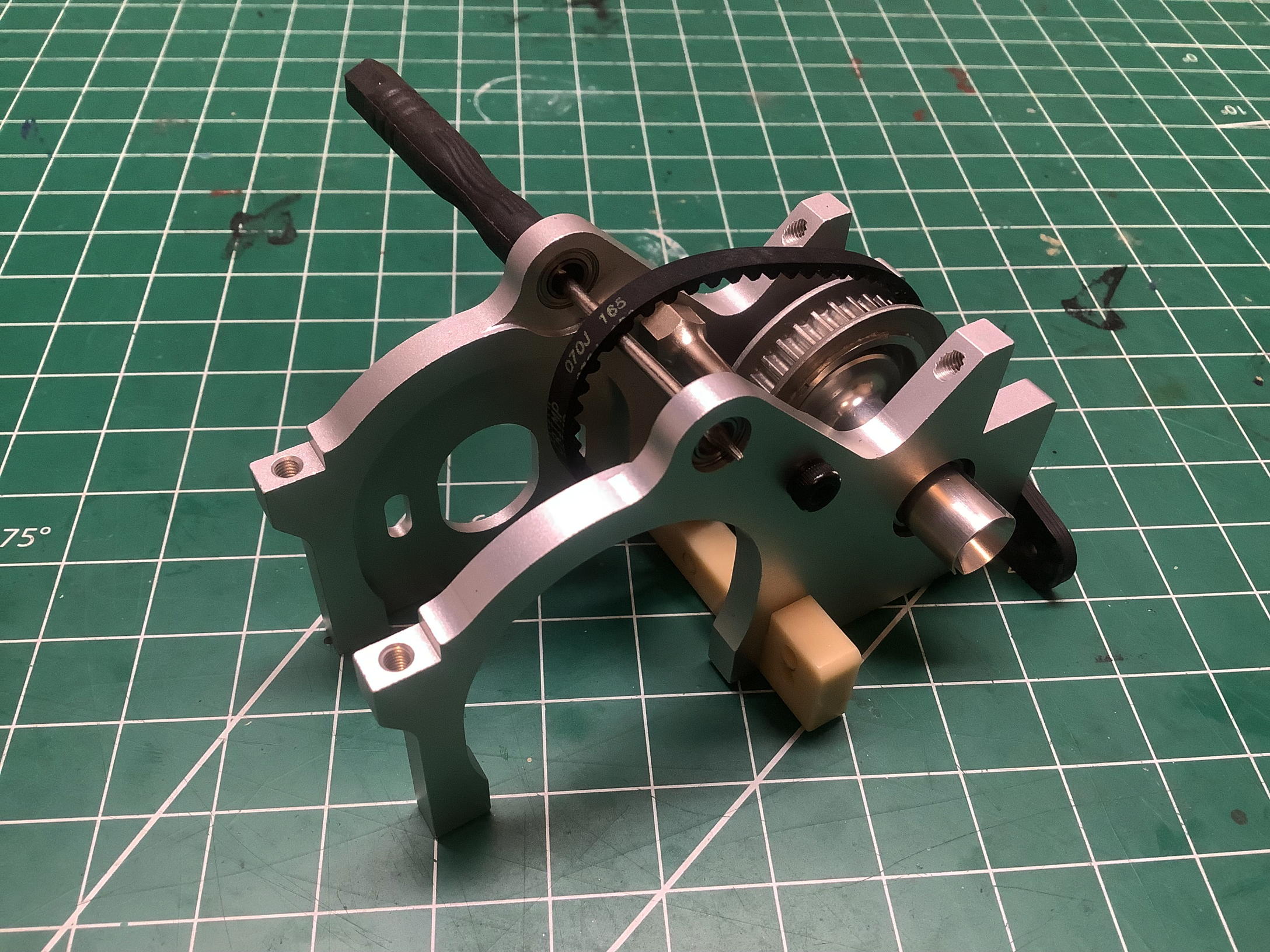
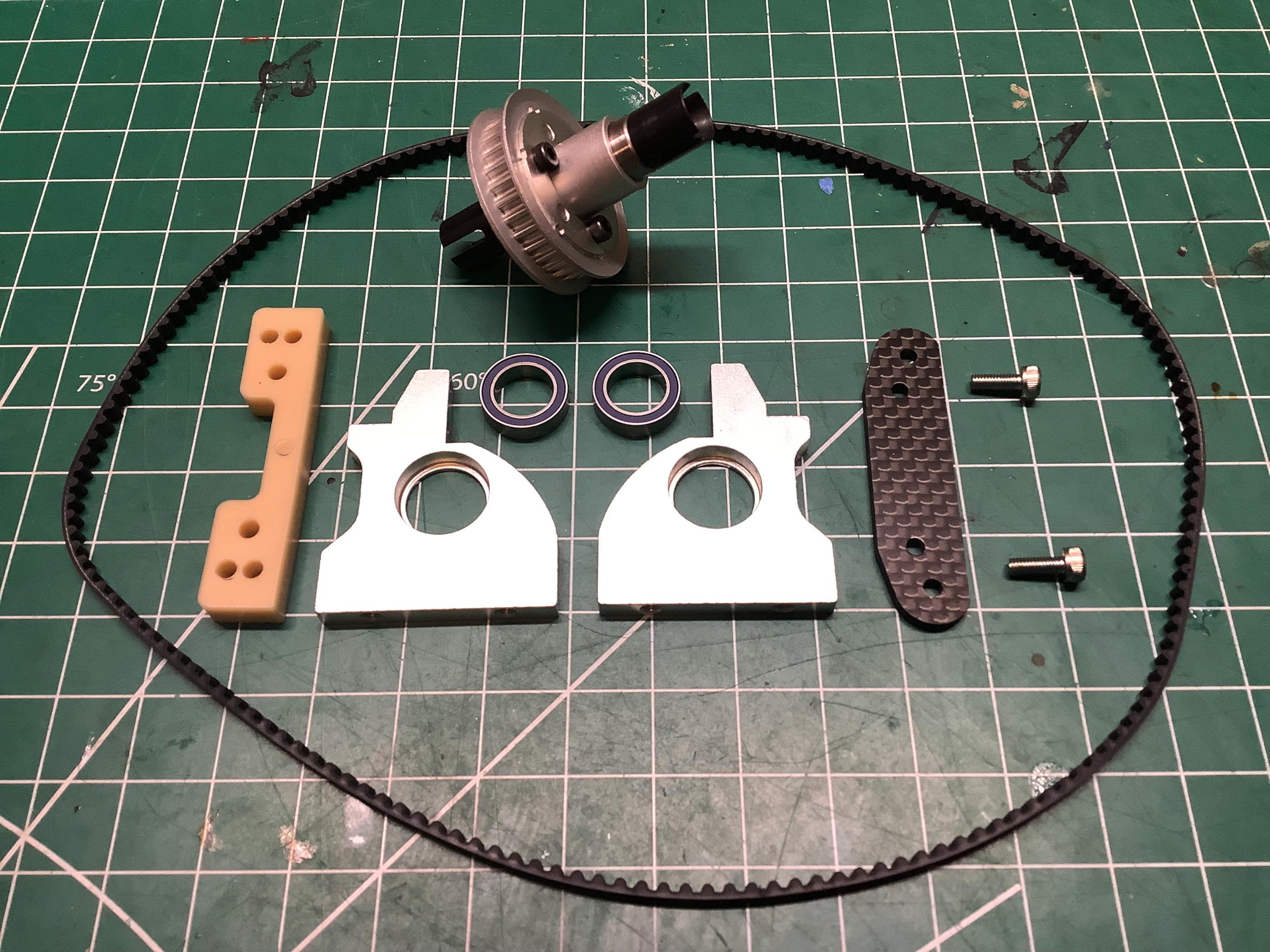
Time to assemble the rear bulkhead. The side panels are machined
aluminum. The manual shows that these come with bearings already
pressed into them, but I didn't notice that until I'd already knocked
the bearings out to take this photo. Luckily I did not damage
anything in the process. The rear suspension mount is a carbon
fiber plate while the forward mount appears to be machined Nylon and
will add lateral support to the whole assembly. The short rear
belt has to be installed over the pulley now because it won't be
accessible later. The motor mount plate is integral with the rear bulkhead.
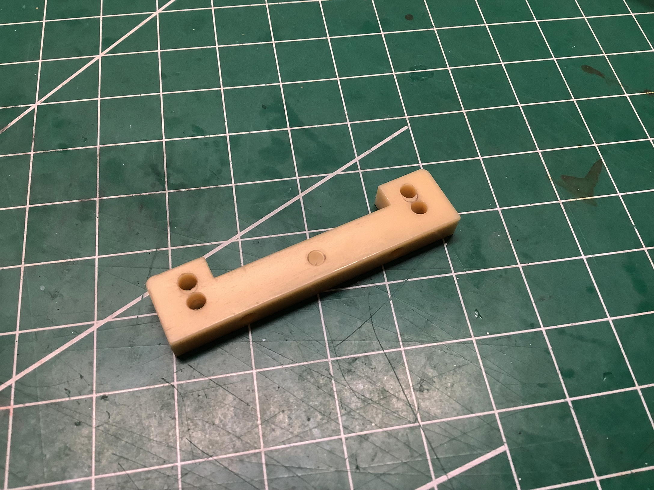
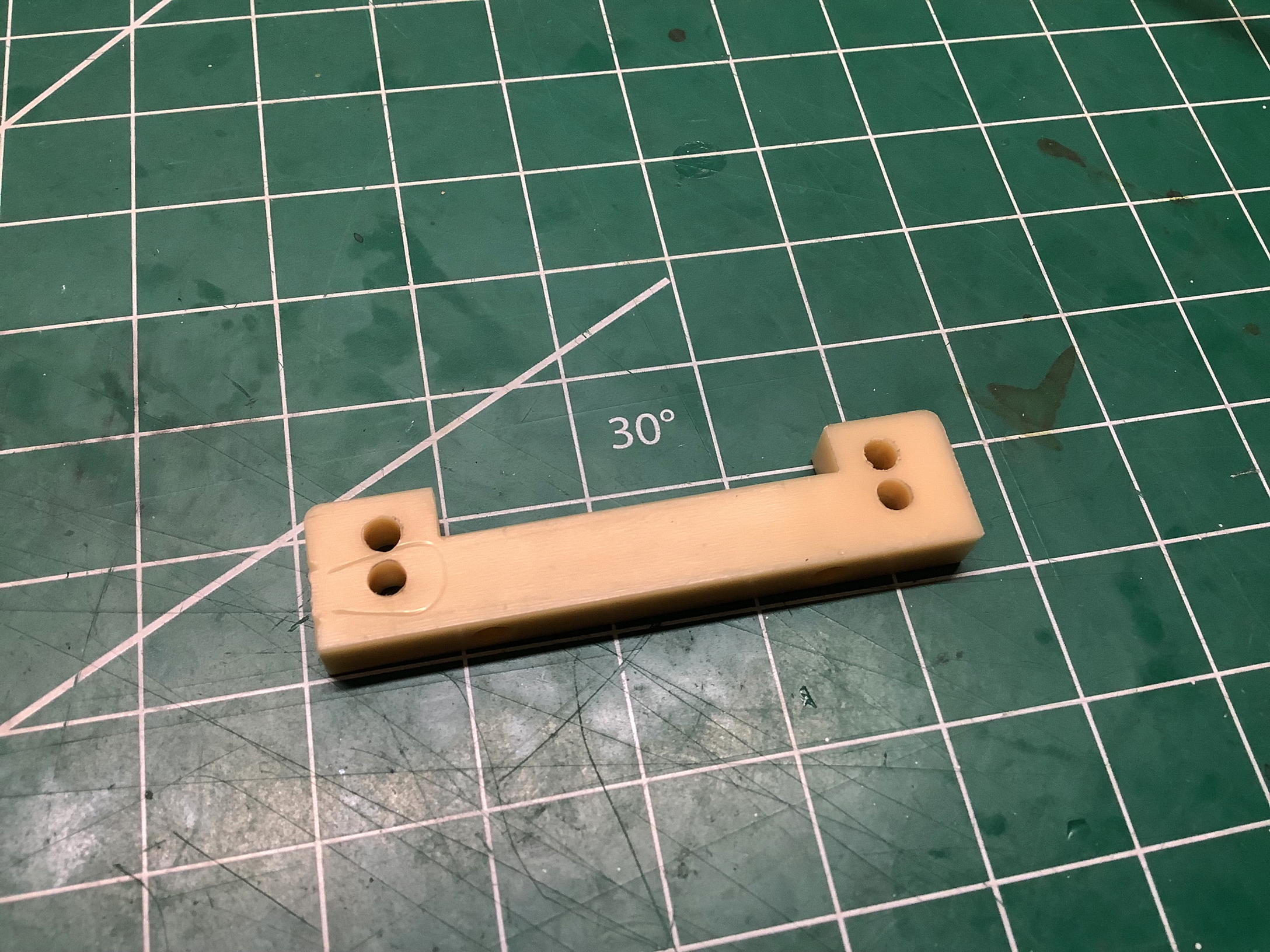
These photos compare the forward suspension mount from each side.
Note that one side has an indentation in the middle. This feature
is there to identify which direction faces forward. Why should it
matter? If you look very closely, you'll see that the holes are
very slightly closer to the top of the part on one side than the
other. That's because the holes have been drilled at an angle that
is not perpendicular to the face.
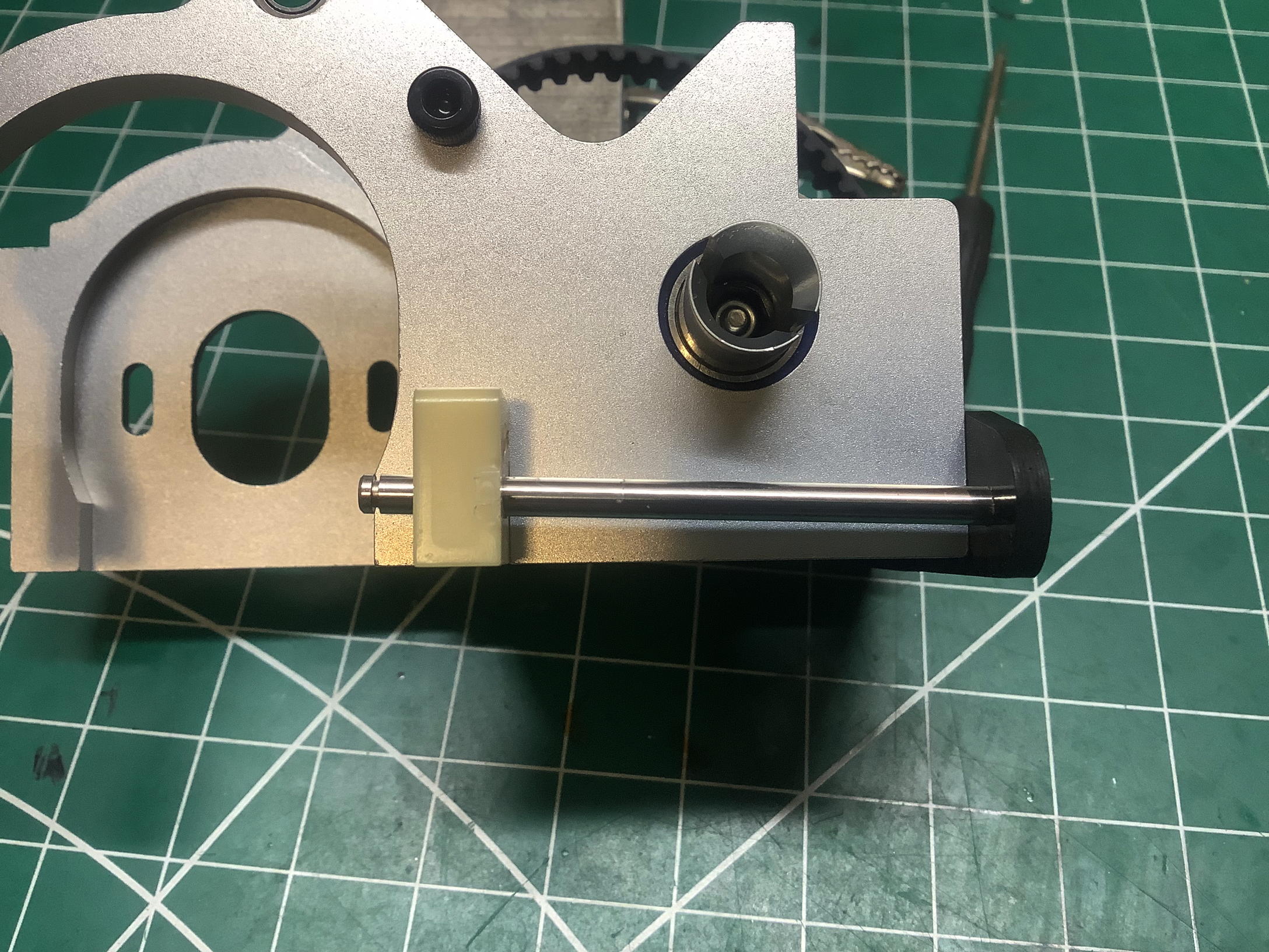
The picture on the left shows the results of those angled holes.
The inner suspension pivot is not parallel to the chassis plate, but
angles down toward the back which results in a positive skid
(or anti-squat) angle. Note that the carbon rear suspension mount does not have a
hole drilled at an angle, so the hinge pin needs to be wedged into it
pretty tightly. I've used the default lower hole, but the roll
center can be changed by using the upper hole on the front suspension
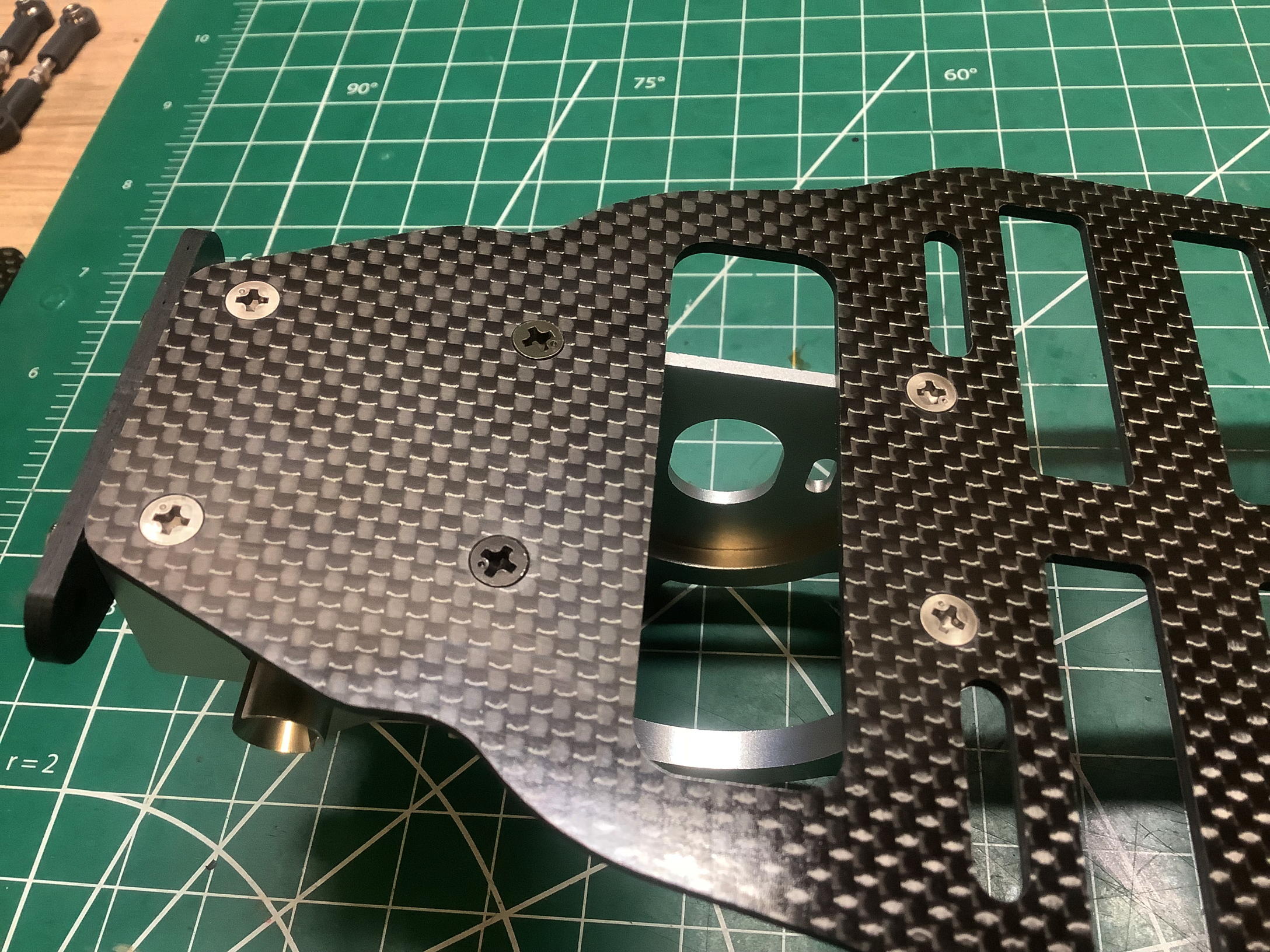
mount and flipping the rear mount upside down. On the right you
can see the bulkhead installed into the chassis as viewed from
below. It really bothers me that two of the screws are steel
instead of titanium. As far as I can tell from the manual, these
ought to be all the same material. Since my version was built in
Japan a year after the original release, perhaps they ran out of
stock. I don't have another explanation for the swap. I was
eventually able to find some replacement Tamiya 3x18mm titanium JIS flat
head cap screws to replace them, but it wasn't easy (or cheap).
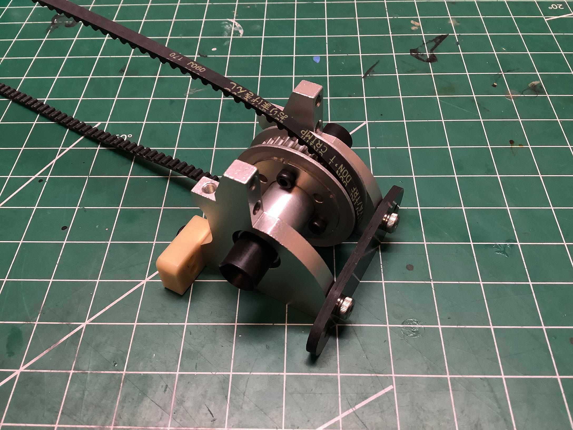
The front bulkhead assembly proceeds much like the rear except that
we're using a one-way here and a longer belt. The assembled result
is shown on the right.
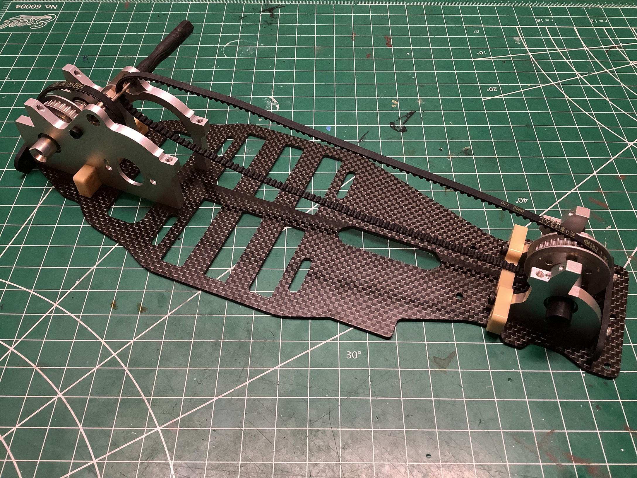
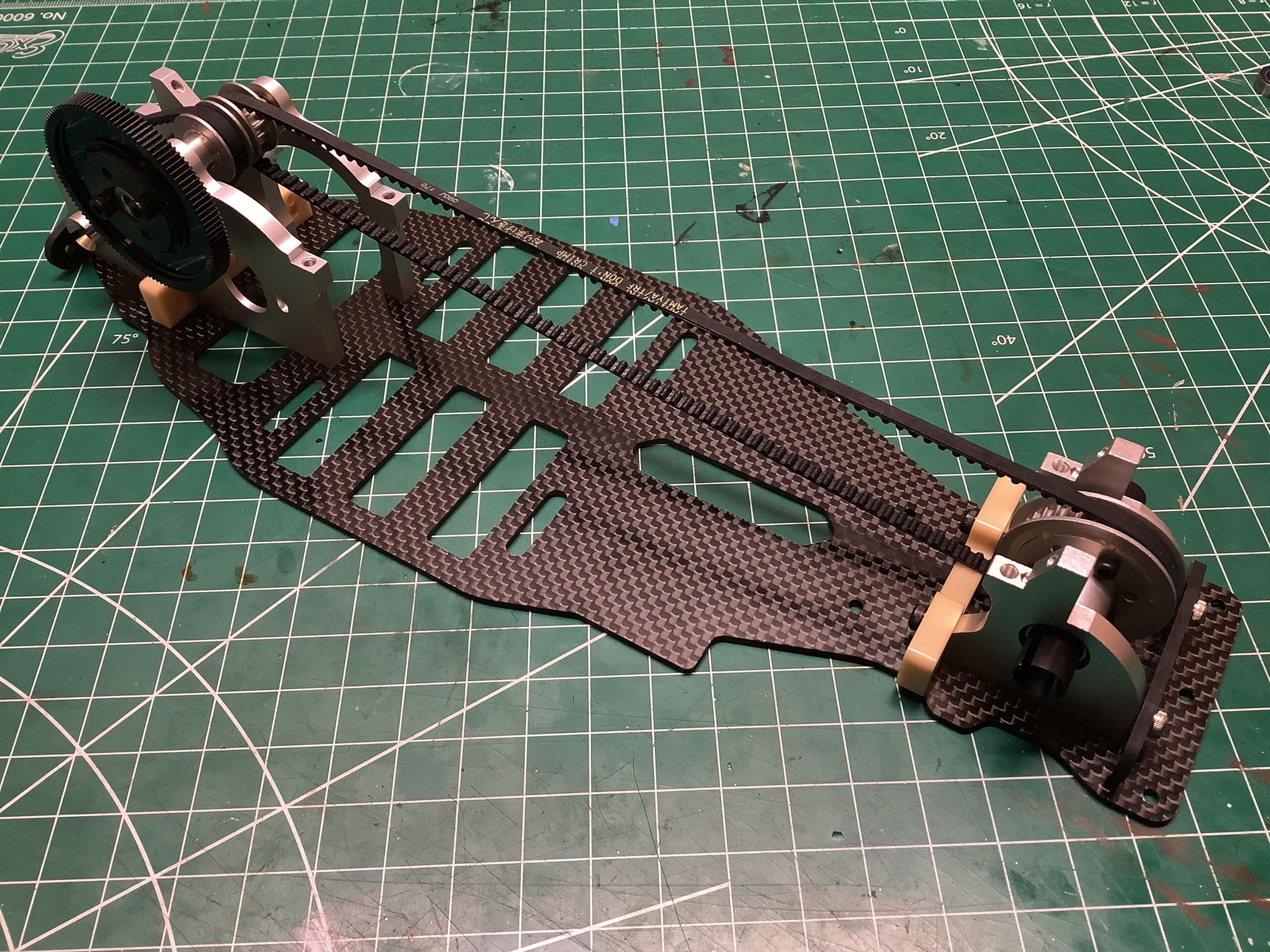
Here is the chassis with both bulkheads installed. I'm using a
tool as a temporary holder for the belts until the center drive pulley
goes in. This is also the first full view of the chassis plate
I've shown which reveals how the batteries are configured. This
chassis is set up for saddle packs with 3 sub-C cells on either side of
the belt (lithium batteries were not a mainstream thing yet in 1999).
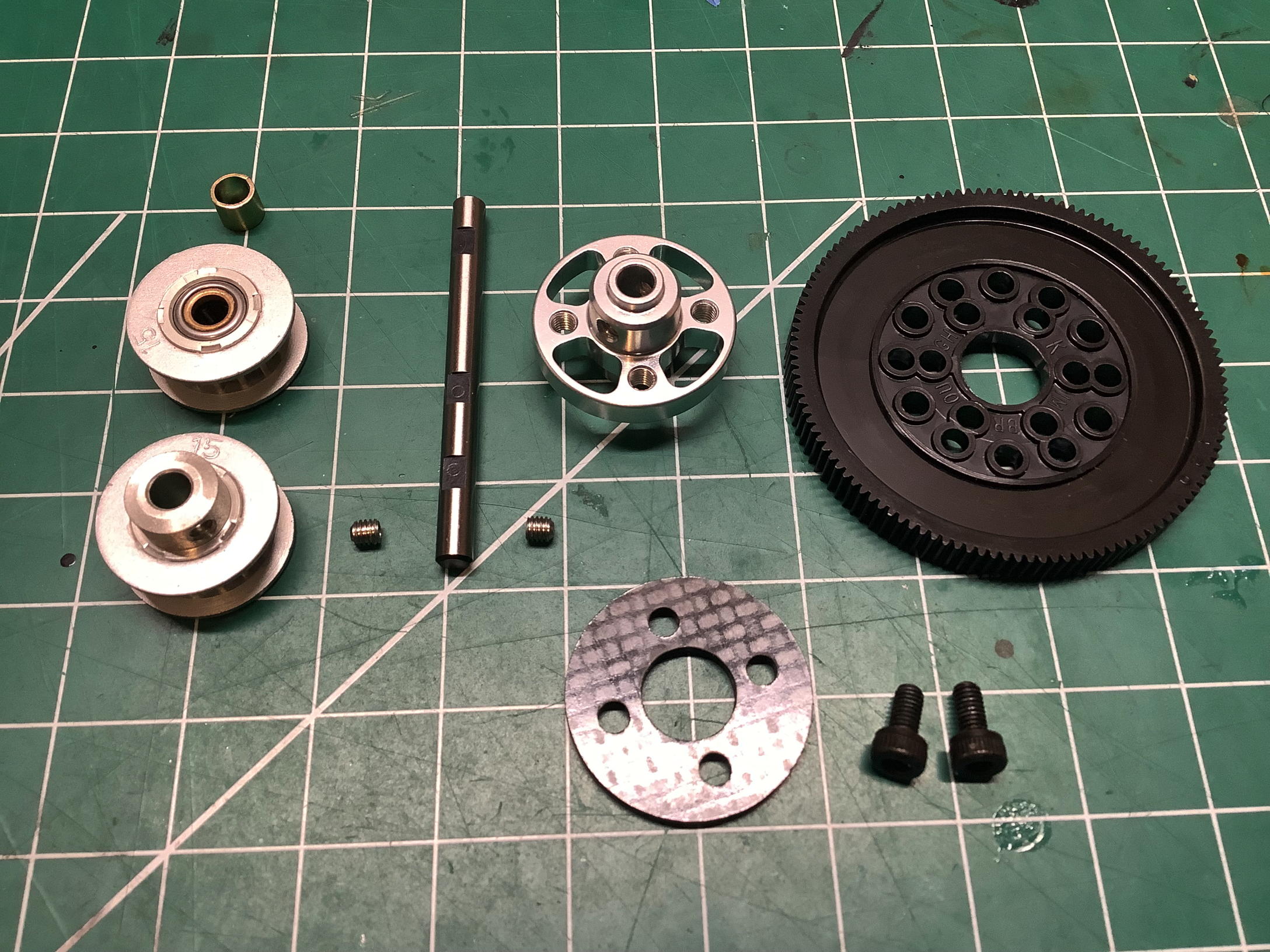
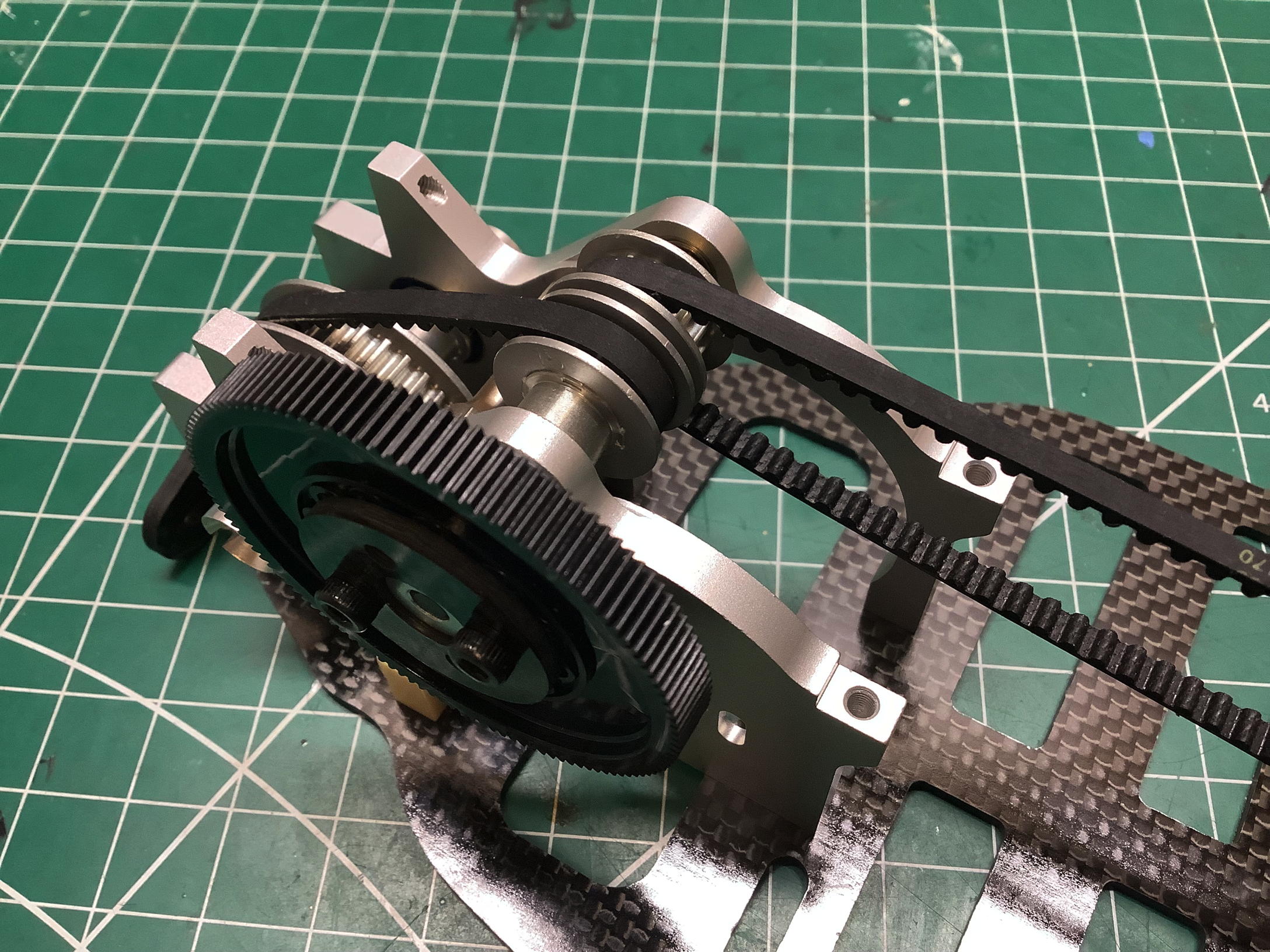
Time to install the center pulley shaft and spur gear. The 93013
kit came with a 15T pulley locked to the shaft to drive the rear axle, and
either another of the same or a one-way to drive the front axle.
My built version only included the one-way. I've never quite
understood why you need a one-way both on the center shaft and also on
the axle, but this chassis has both. The carbon reinforcing plate
you see here for the spur gear was not part of the 93013 kit but did come with the later
49132 TRF414 from 2000. Since my built version of the 414X came
from 2000, it appears to have included this "upgrade". Note that
the model that came out of the Stealth Box as built did not have the
spur gear installed at all.
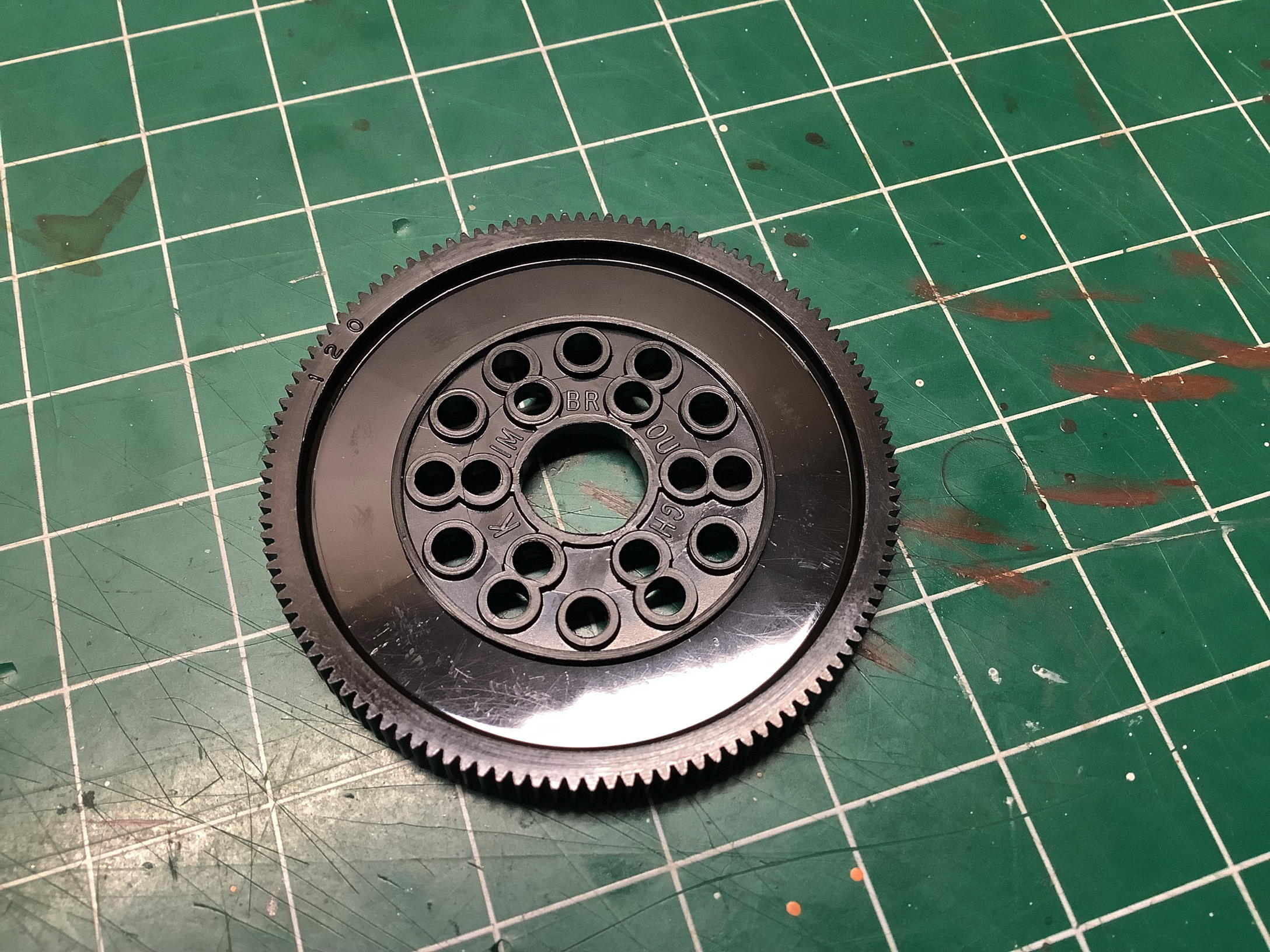
The 120T spur gear is actually not a Tamiya part. Since racers
tended to use 64p pitch rather than the metric 0.4 mod equivalent,
Tamiya chose to include a racing spur from Kimbrough. The center
shaft is installed as shown on the right, so now the belts can be
rotated and tested. Note that there is no belt tension adjustment in
the hubs.
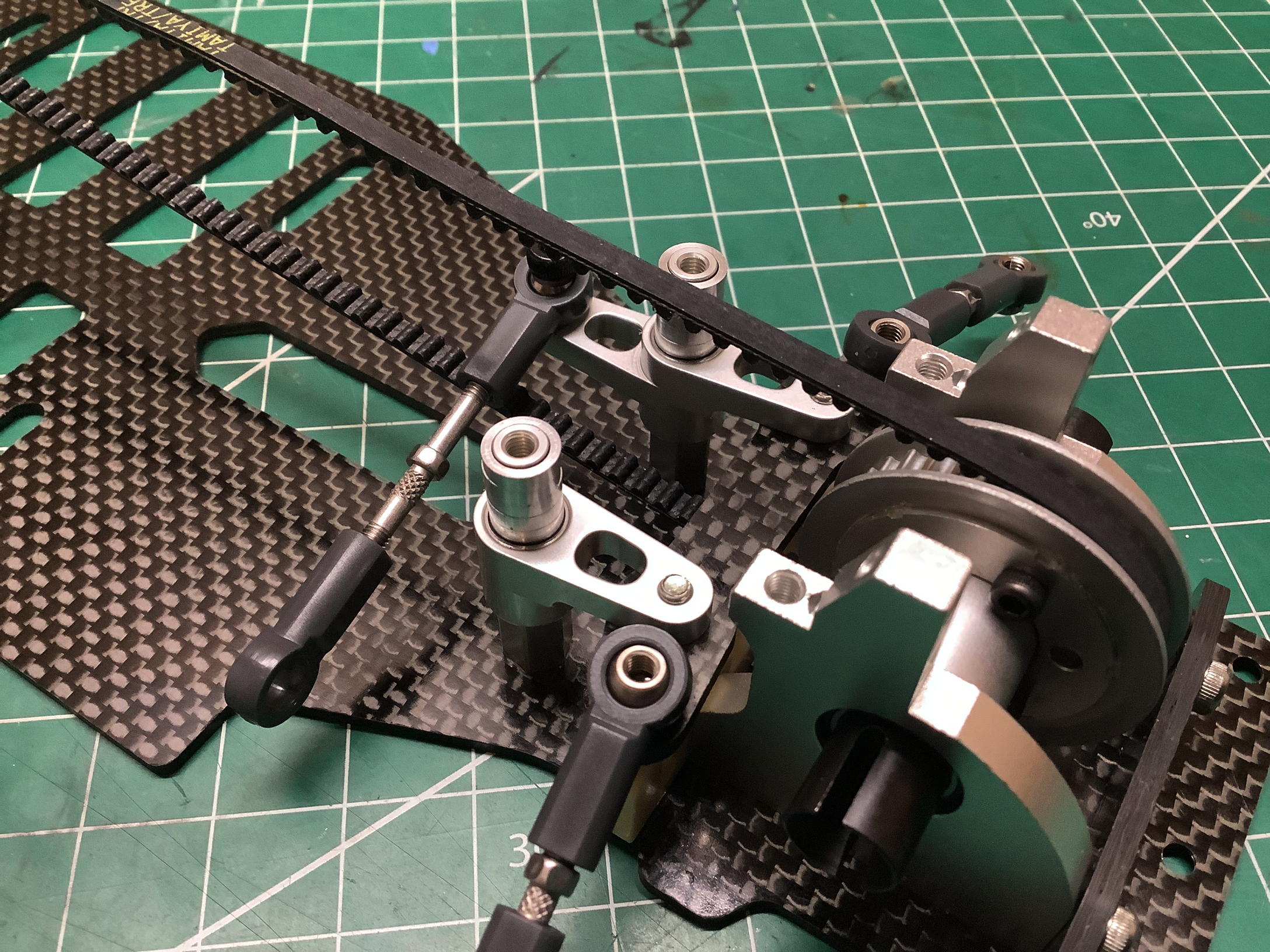
Now we can install the steering bellcrank assembly onto the chassis
plate using the posts and spacers shown. In order to get the
steering bridge to sit at the right height to pass between the top and
bottom of the belt, all 5 spacers need to go on top of each post.
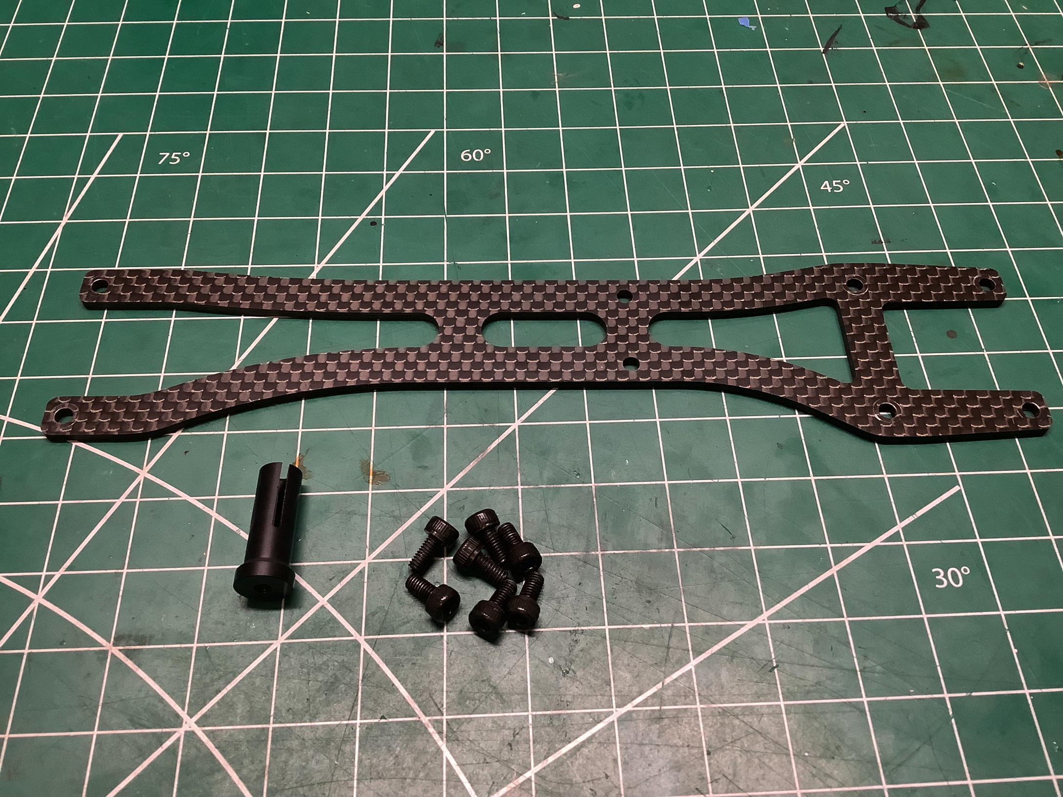
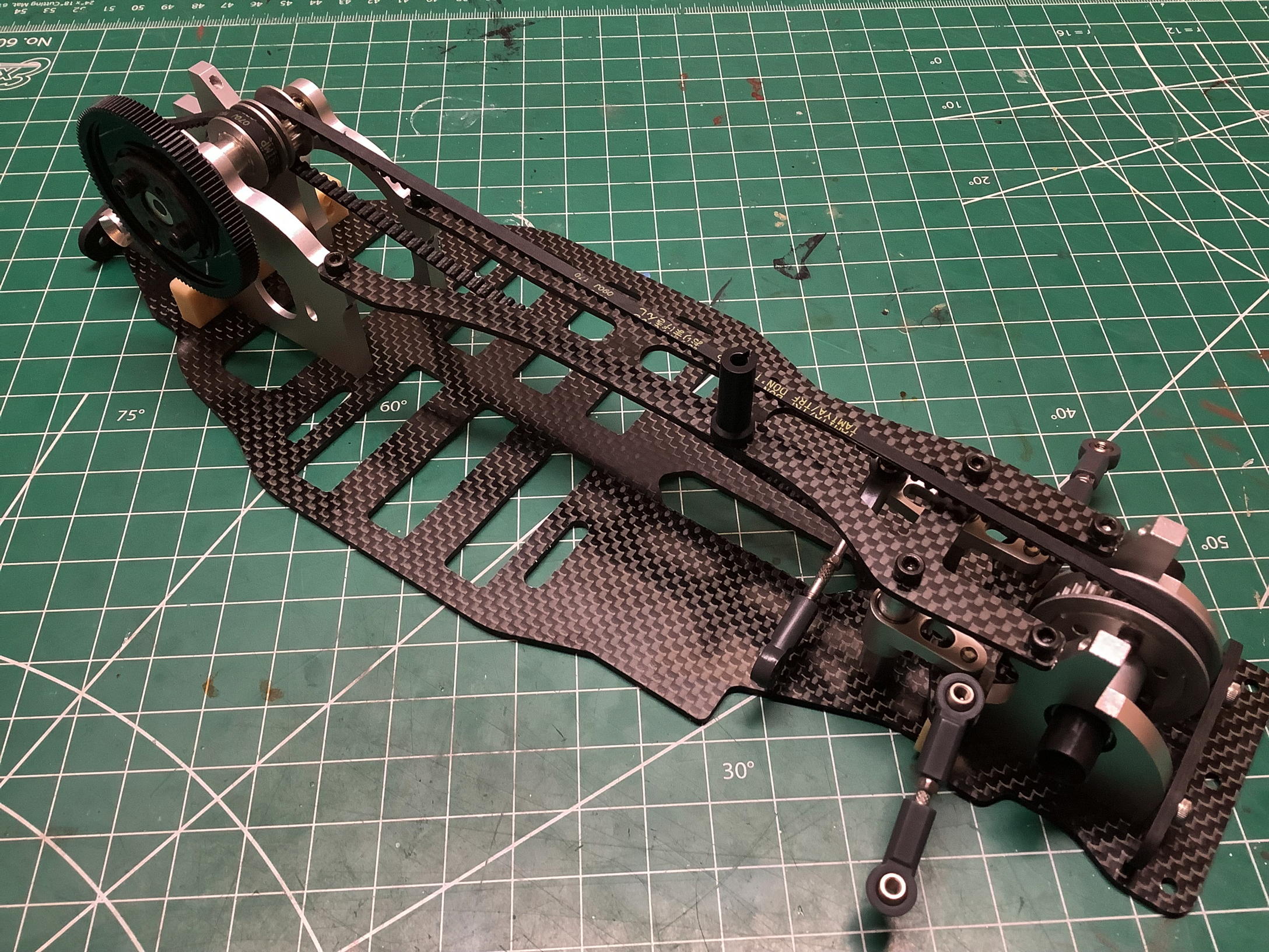
Now the asymmetric upper chassis plate can be installed with a receiver
antenna mount. This plate also ties the front bulkhead to the tops
of the steering posts. Everything is massively stiffened after
this is installed. Why is it asymmetric? I can't find any
particular reason for the extra space allotted to the right side by this
design.
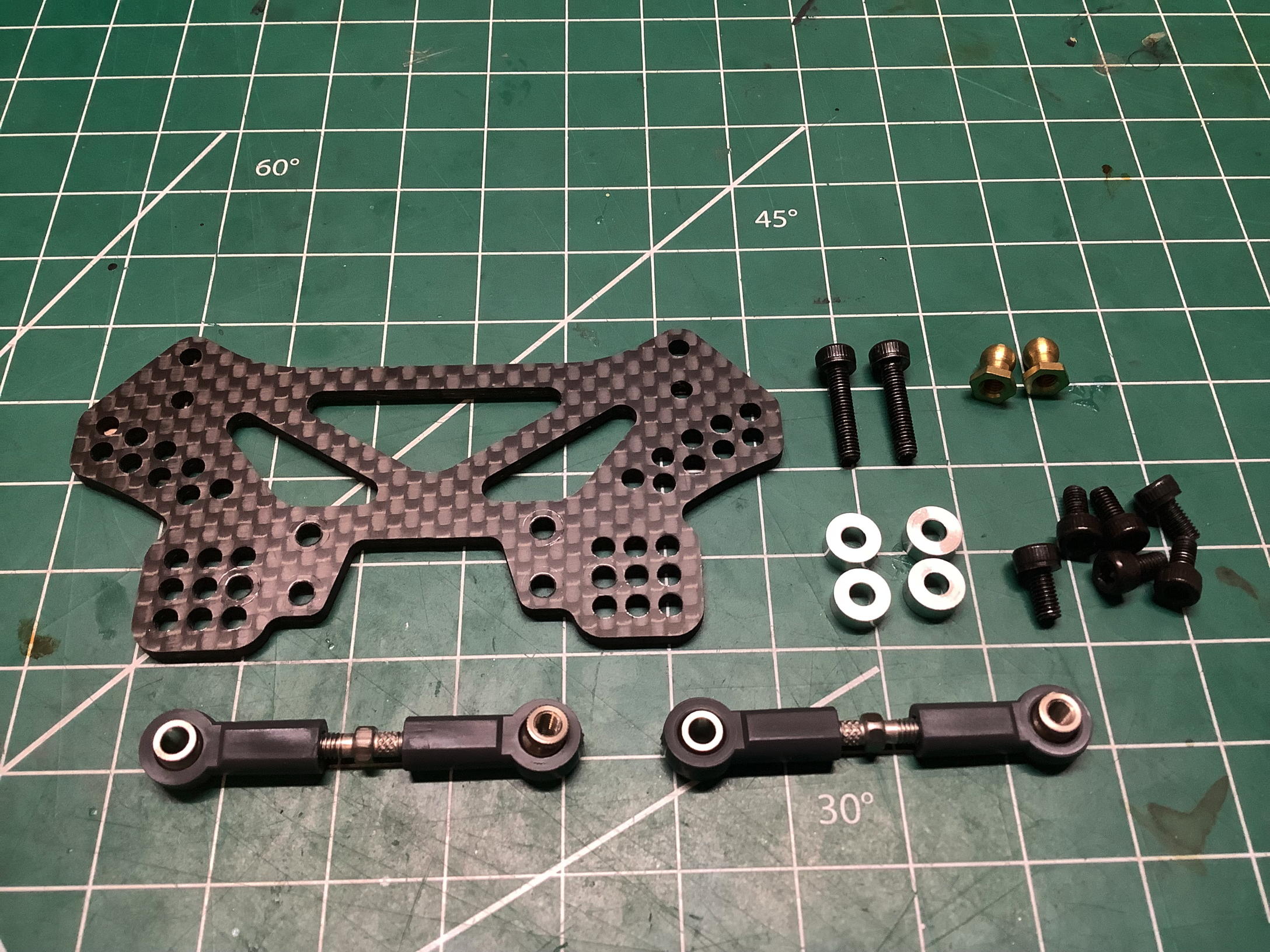
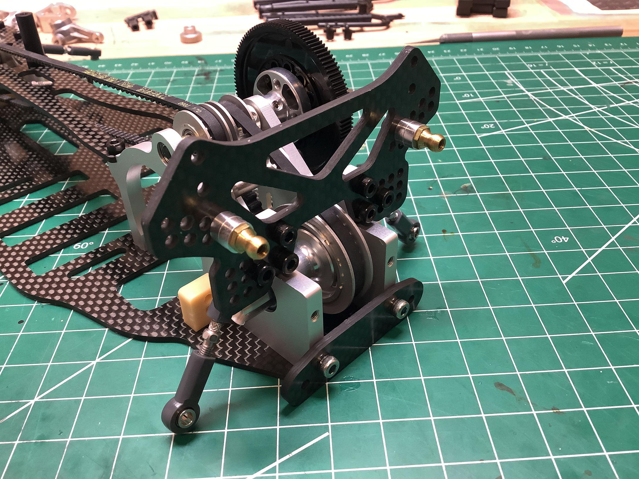
The rear shock tower comes with a lot of options. There are 9
holes on each side (arrayed in a grid) for connection of the upper
suspension link, and also 9 holes on each side (arrayed in an arc) for
connection of the upper shock mount. I used the holes indicated as
default in the manual because I don't know any better.
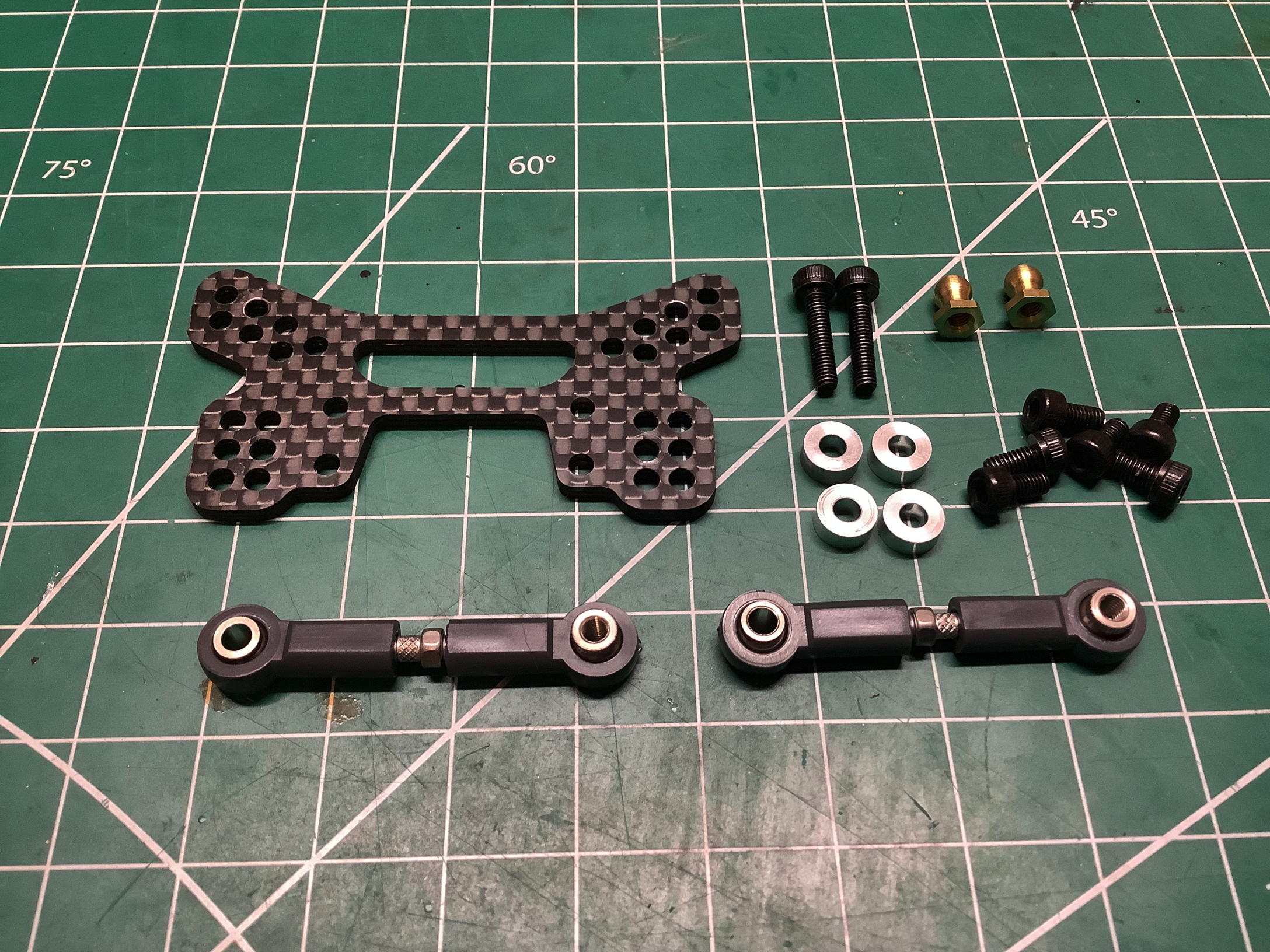
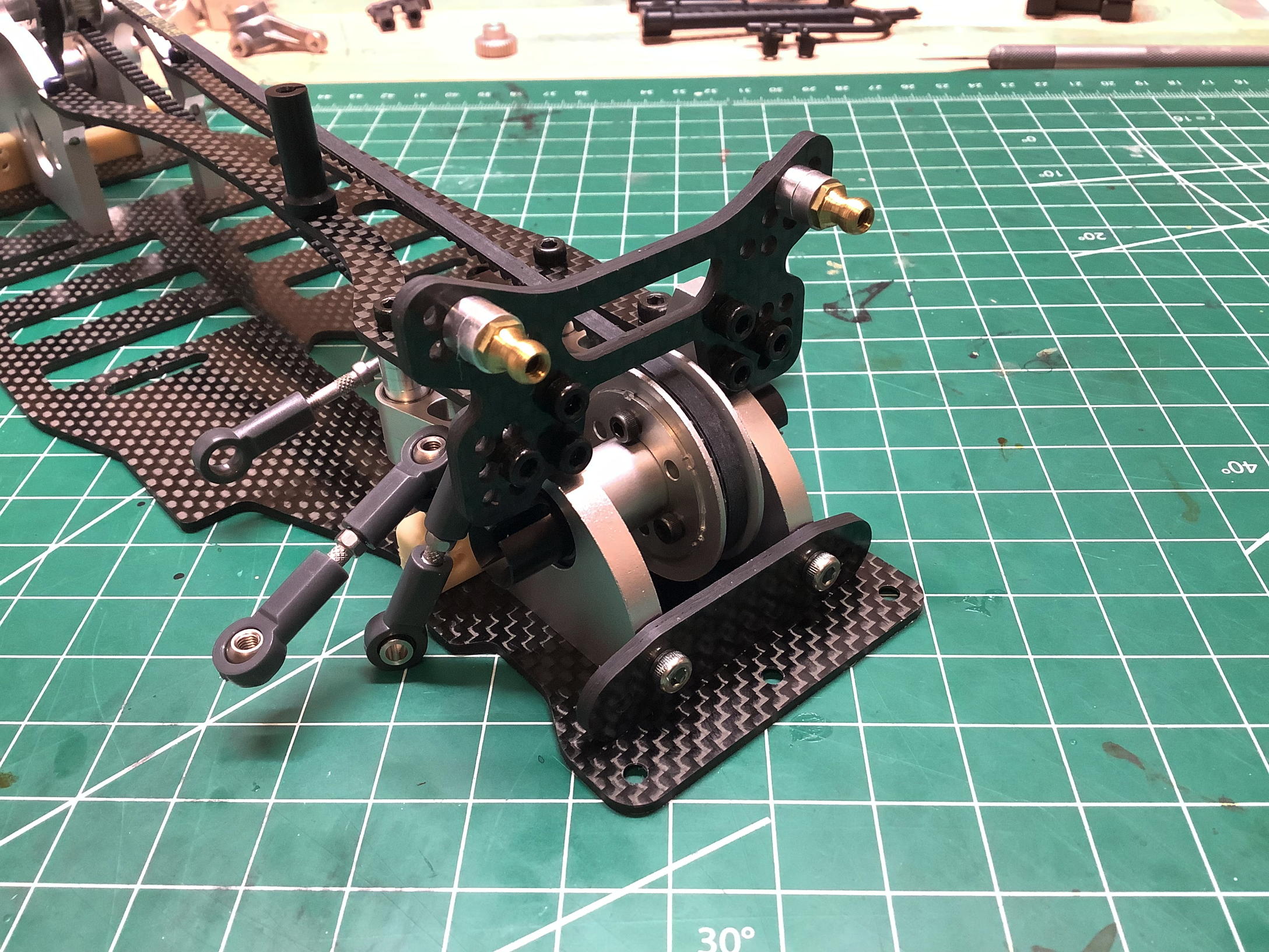
The front shock tower offers slightly fewer options for link attachments
than the rear (6 or 7 at each location instead of 9), but it is still a
very customizable configuration. It is shown installed on the
right. Both shock towers are reused on the TRF 414 production
model, but simplified for the TRF 414M with the same overall shape but
fewer holes.
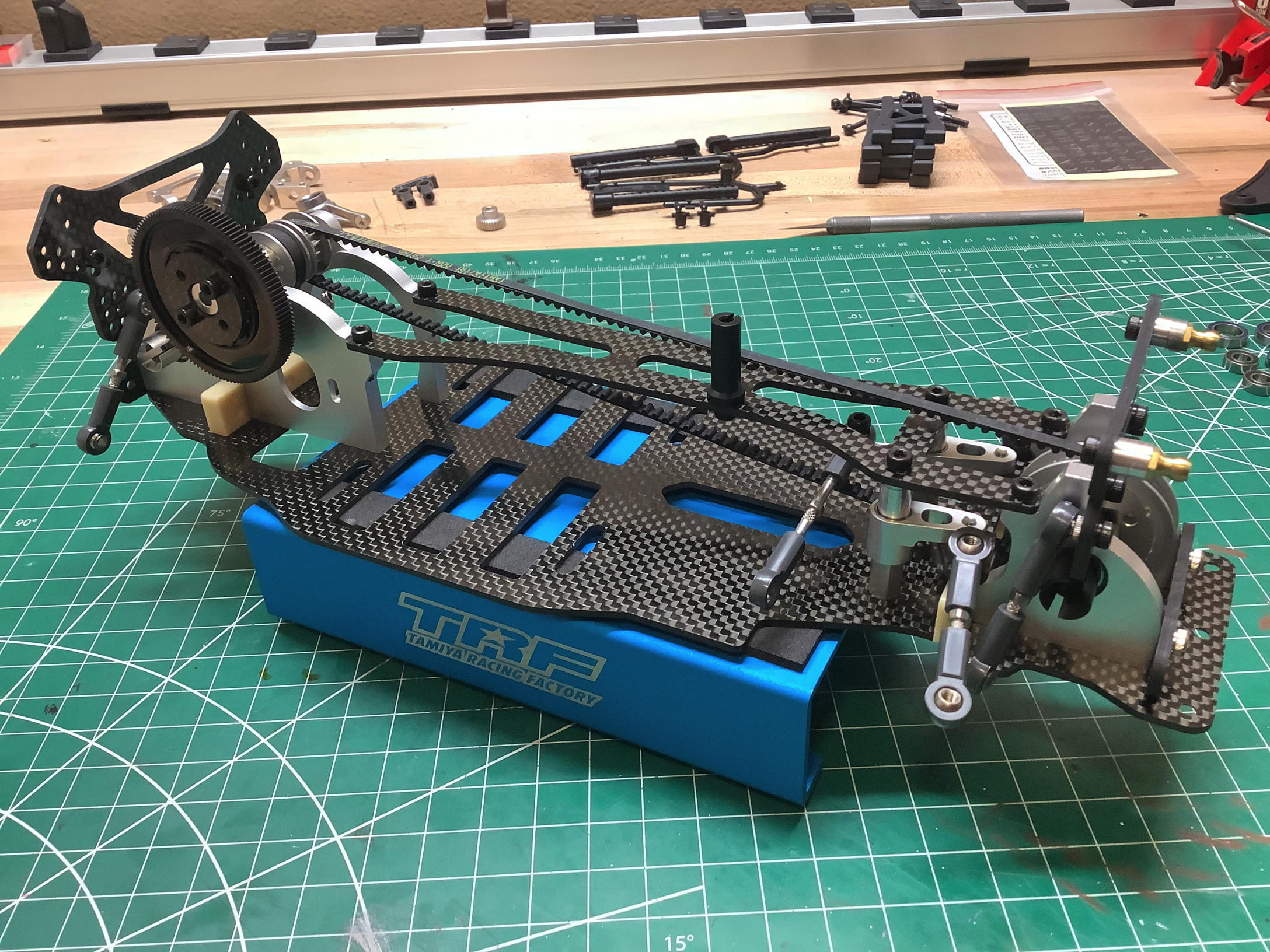
Here is the chassis with both shock towers installed onto the bulkheads. Time to build the suspension.
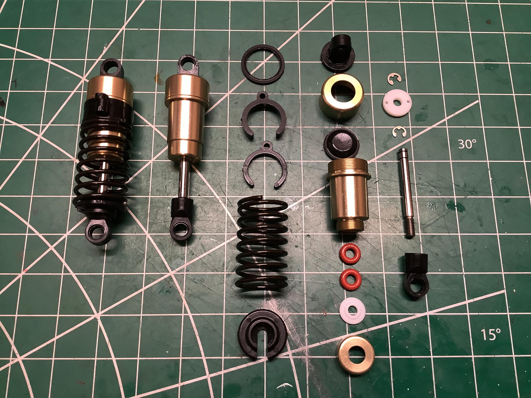
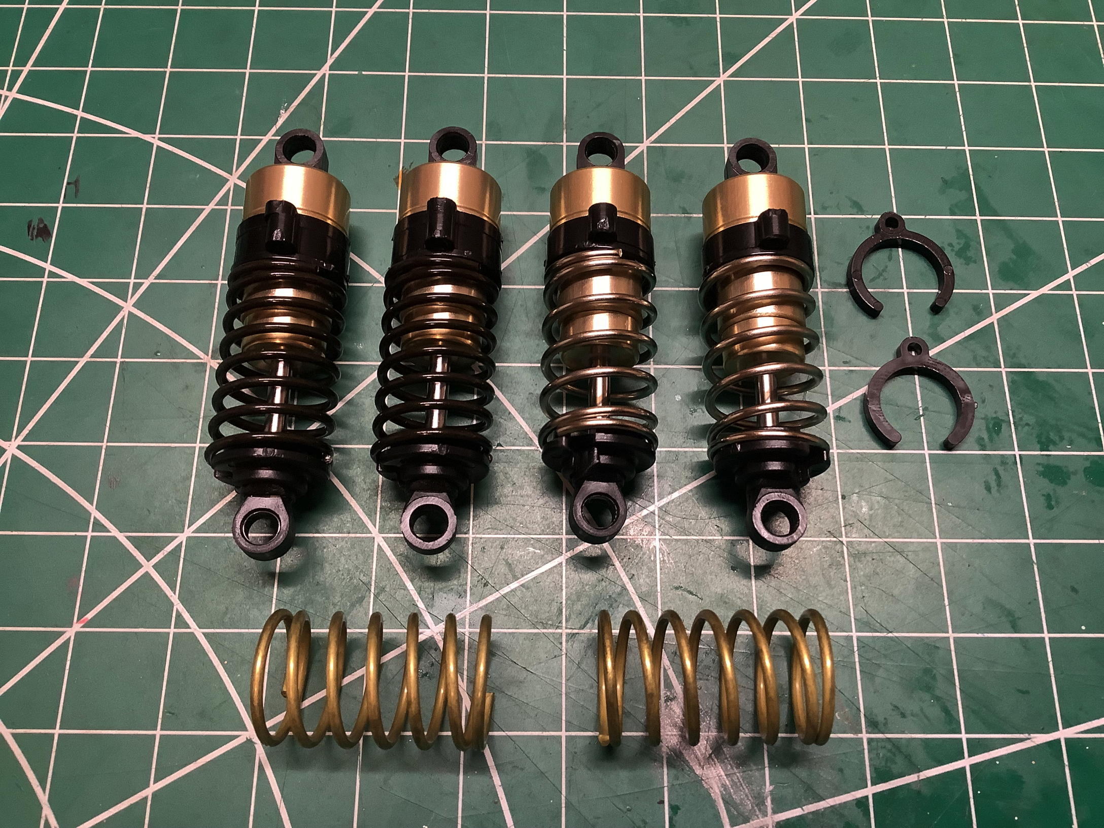
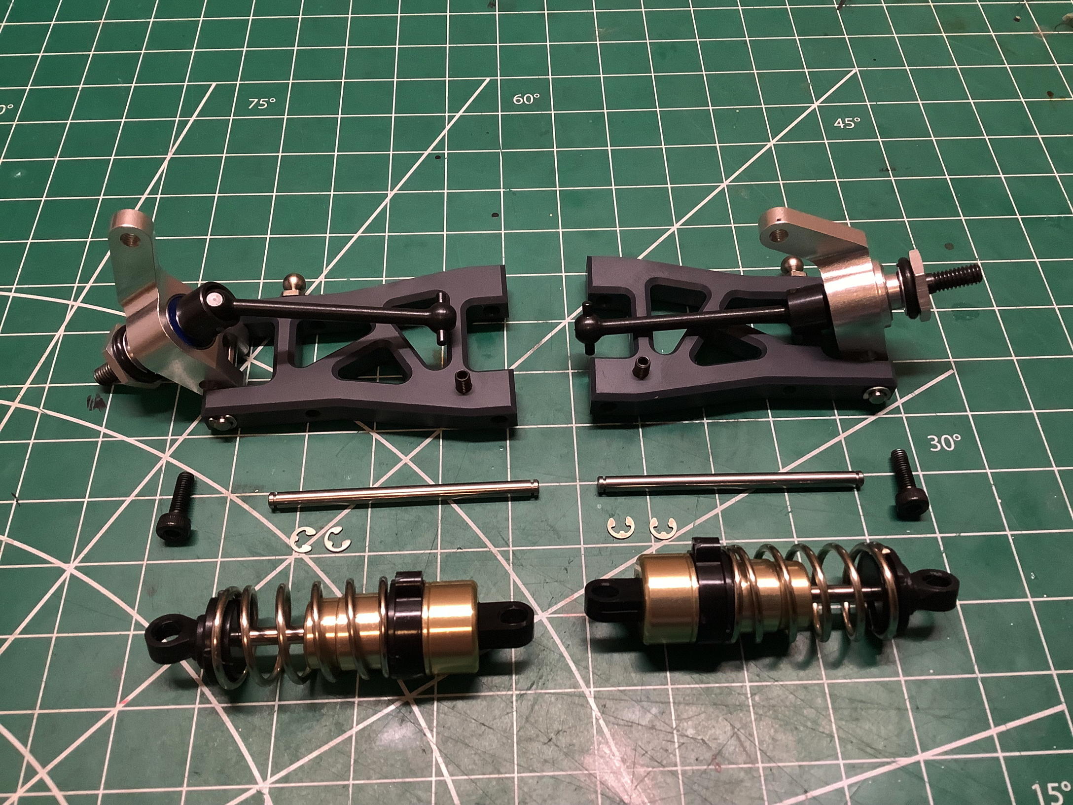
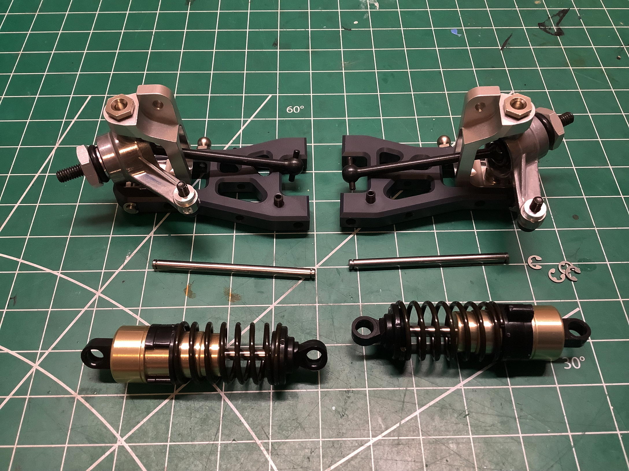
These very early TRF shocks are a thing of beauty. The outside of
the cylinders and caps are anodized in gold. All four shocks use
2-hole Delrin pistons, but front and rear versions use different spring
rates and preload spacers as shown. A third spring rate which is
between the other options is available but unused in the base build.
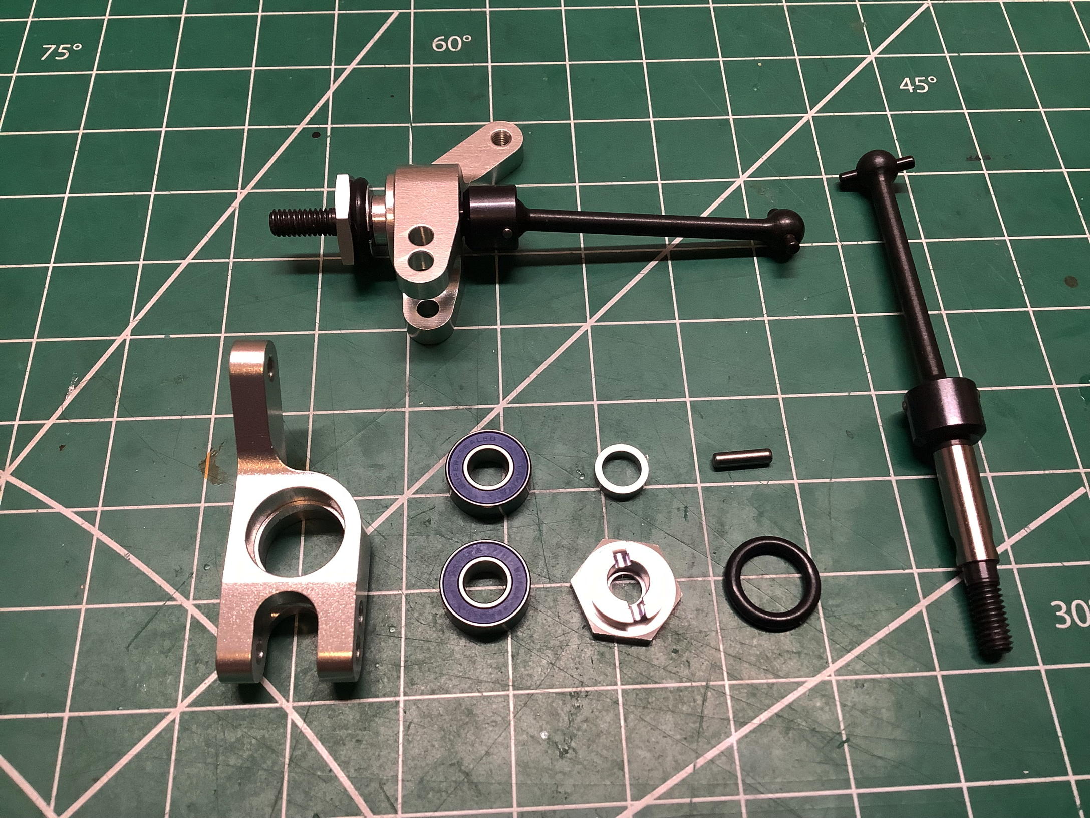
The rear suspension comes first. The uprights are machined
aluminum and the axles have a dogbone at one end and a CVD universal at
the other. The axles come assembled with pressed pins so cannot be
taken apart. The hexes are very thin and the cross pin is
unusually retained with an O-ring. Once built, the hub assembly
attaches to the machined suspension arms with smooth hinge pins retained
by E-clips. A set screw is used to contact the chassis plate and
set the lower limit of suspension travel which controls ride height.
Now the previously completed rear shocks can be attached and the whole
rear suspension assembly connected to the chassis with hinge pins.
The fully assembled rear suspension is shown on the right.
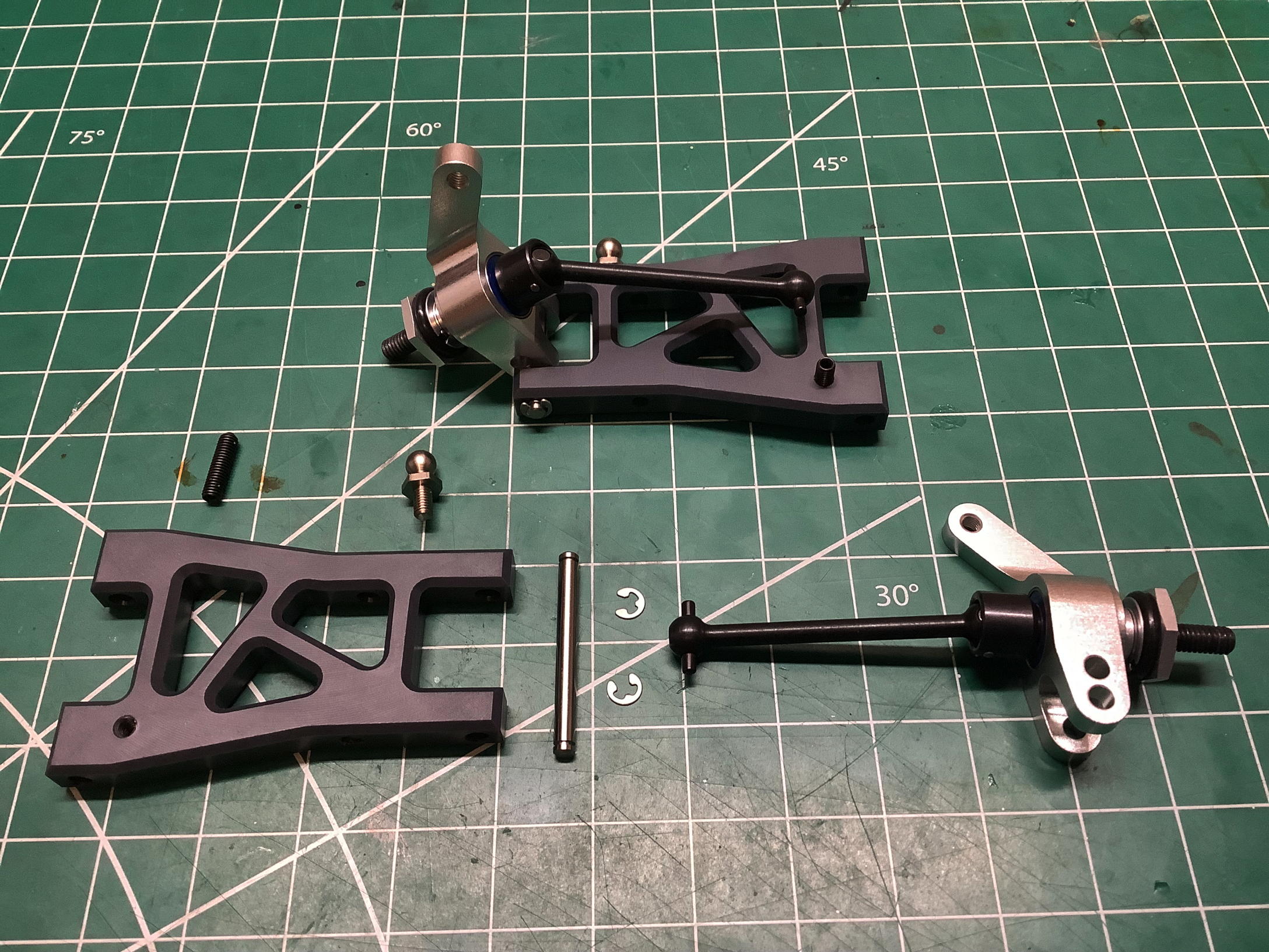
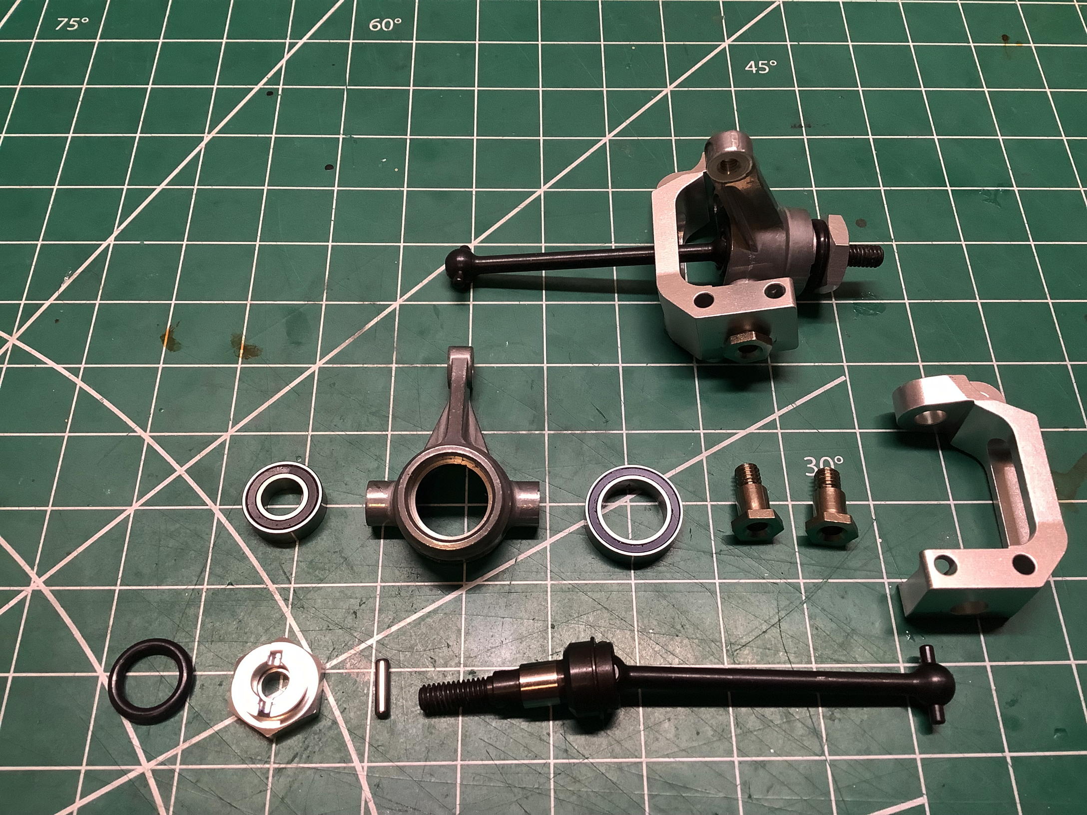
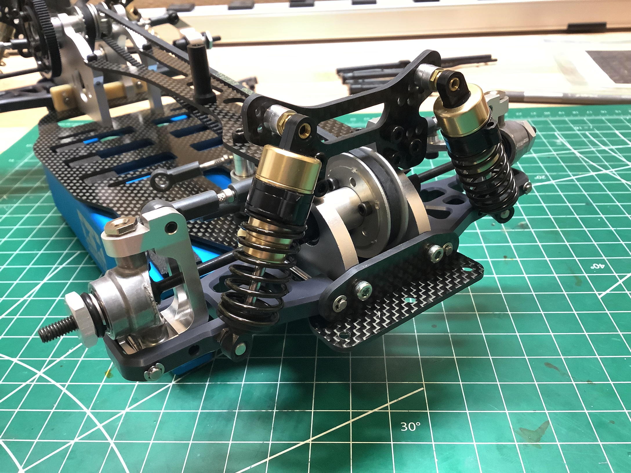
Now we can do the same thing for the front suspension. The C-hubs
and knuckles are both machined aluminum. The king pins are single
piece step screws with a smooth portion to act as a steering
pivot. Everything else goes together very much like the rear.
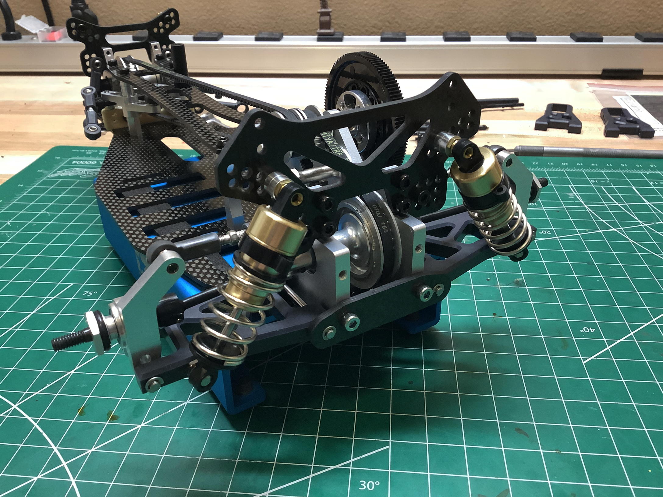
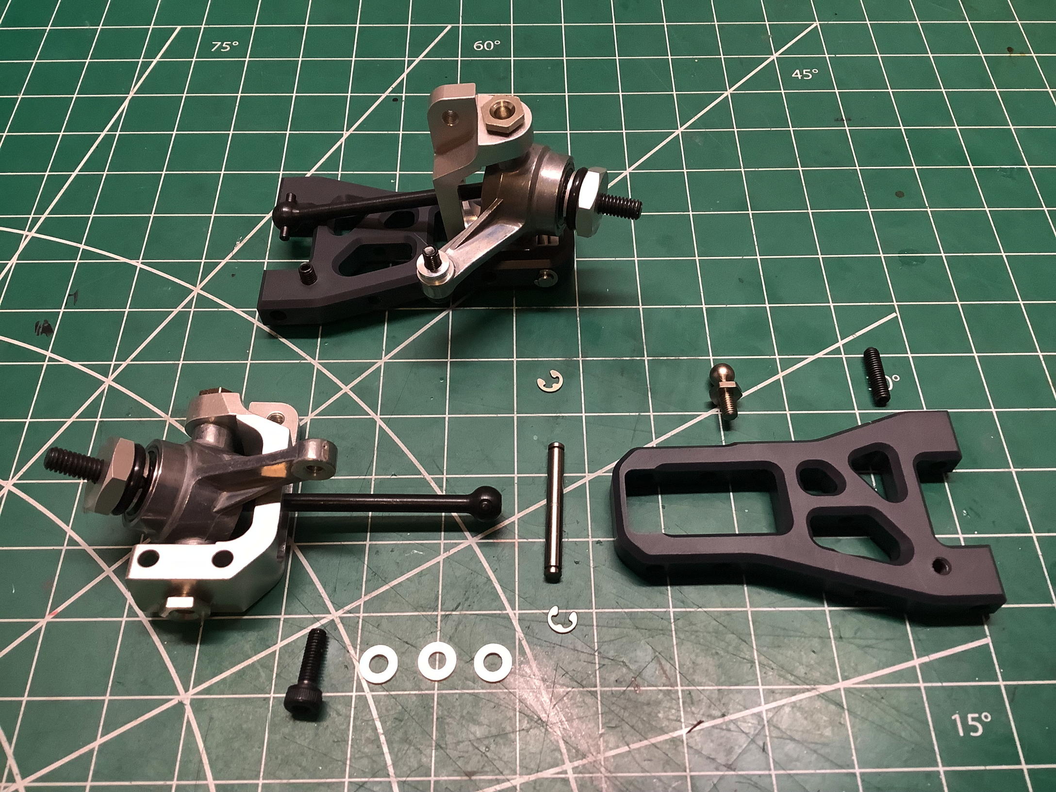
The exploded view on the left shows the components for the front
suspension installation, and the photo on the right shows everything
complete. Note that the upper arms attach to the sides of the hubs
rather than the top. This keeps the arms low, but also introduces
side forces into the hub.
At this point the chassis has been returned to the assembly condition in
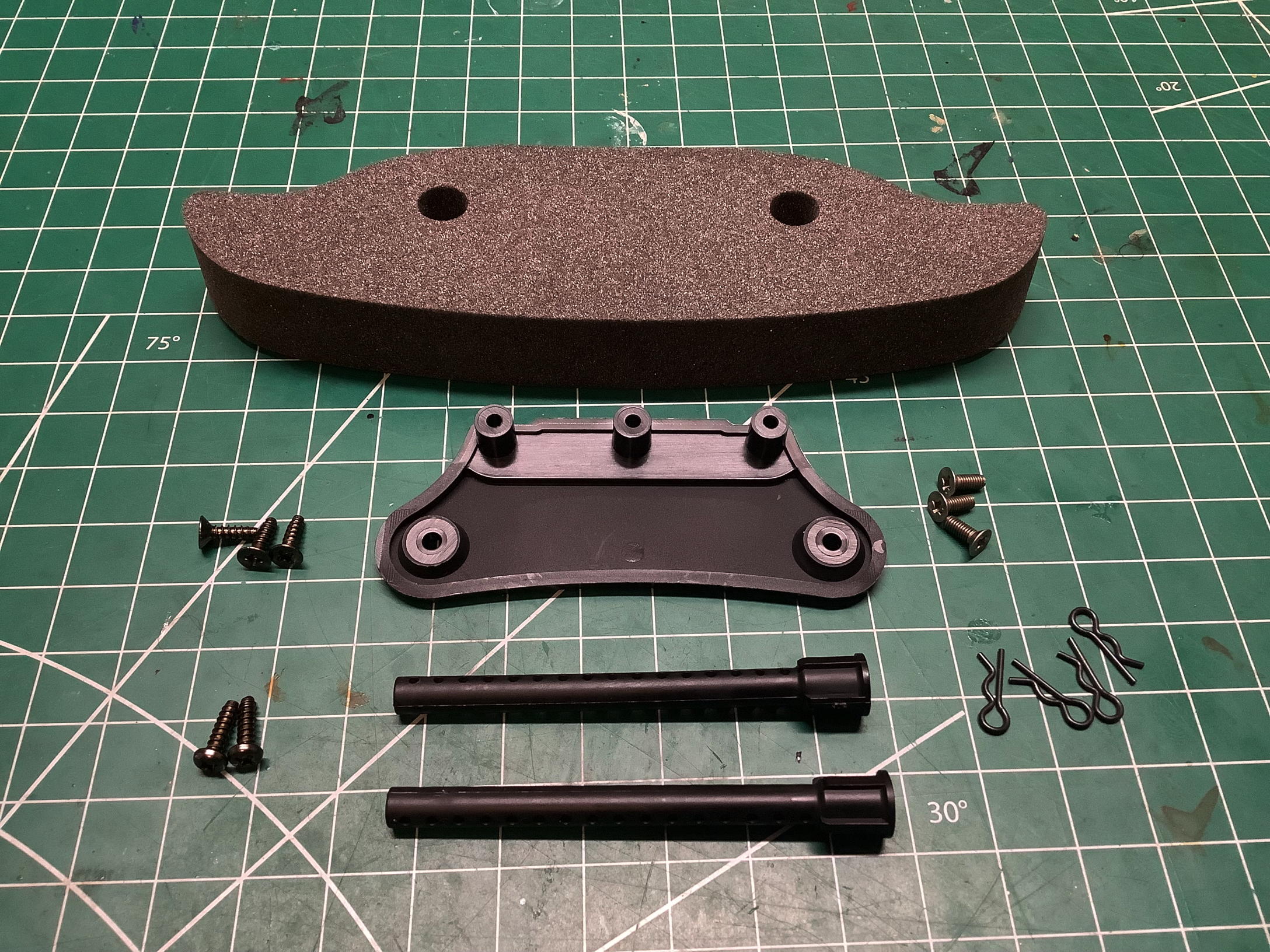
which I received it, but it is not quite done. Neither the bumper
nor the body posts were installed in the hard case so I'll put them on
now. There's nothing out of the ordinary going on here, although
these body posts are unique to this chassis.
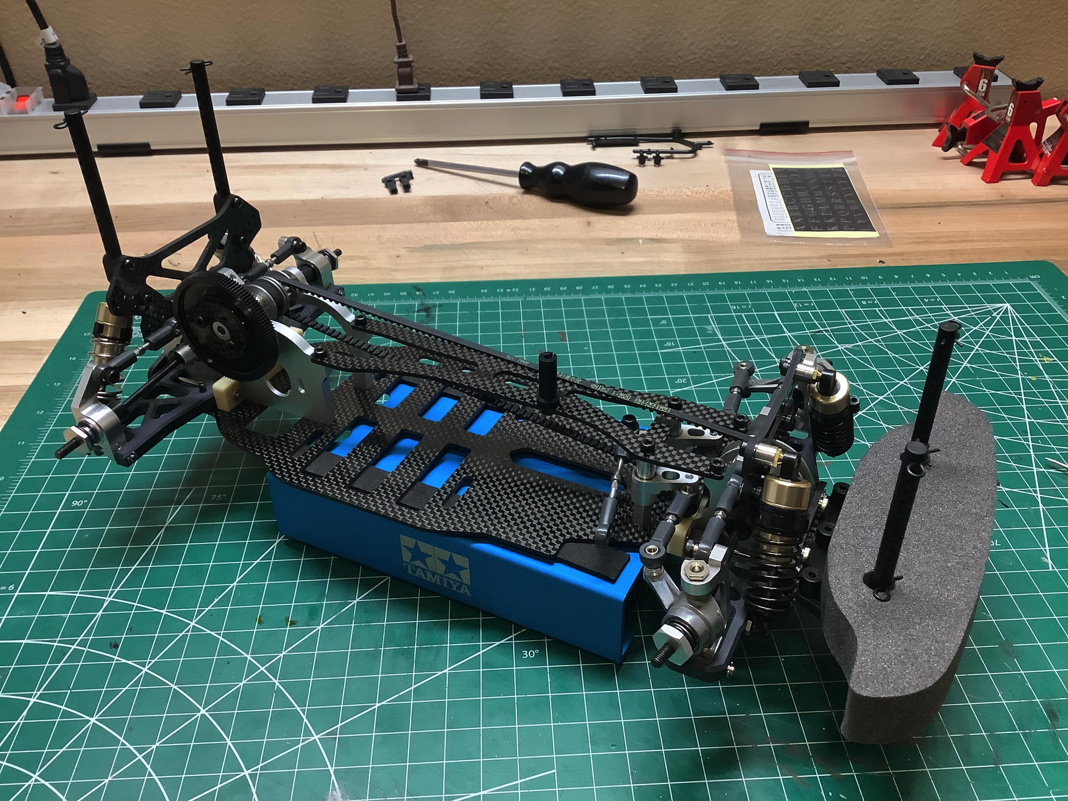
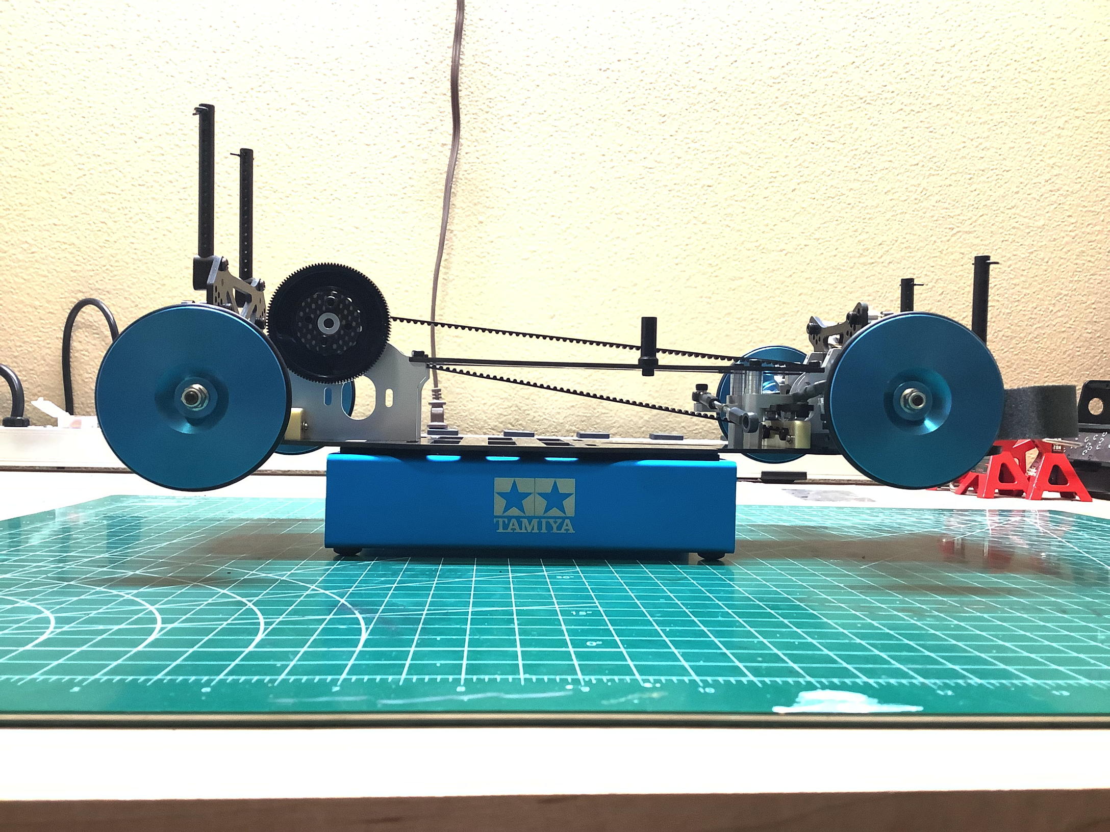
This chassis did not come with any wheels or tires since those would
usually be chosen by the driver for a specific track. Instead this
model came with setting dishes, a type of part I'd heard of but never
seen. These solid aluminum disks are installed in place of wheels
and, having the same outer diameter, provide a platform on which to
perform adjustments and measurements of such parameters as camber,
caster, roll center, ride height, and toe. The dishes have a
larger outer O-ring just to provide a but of friction to keep the
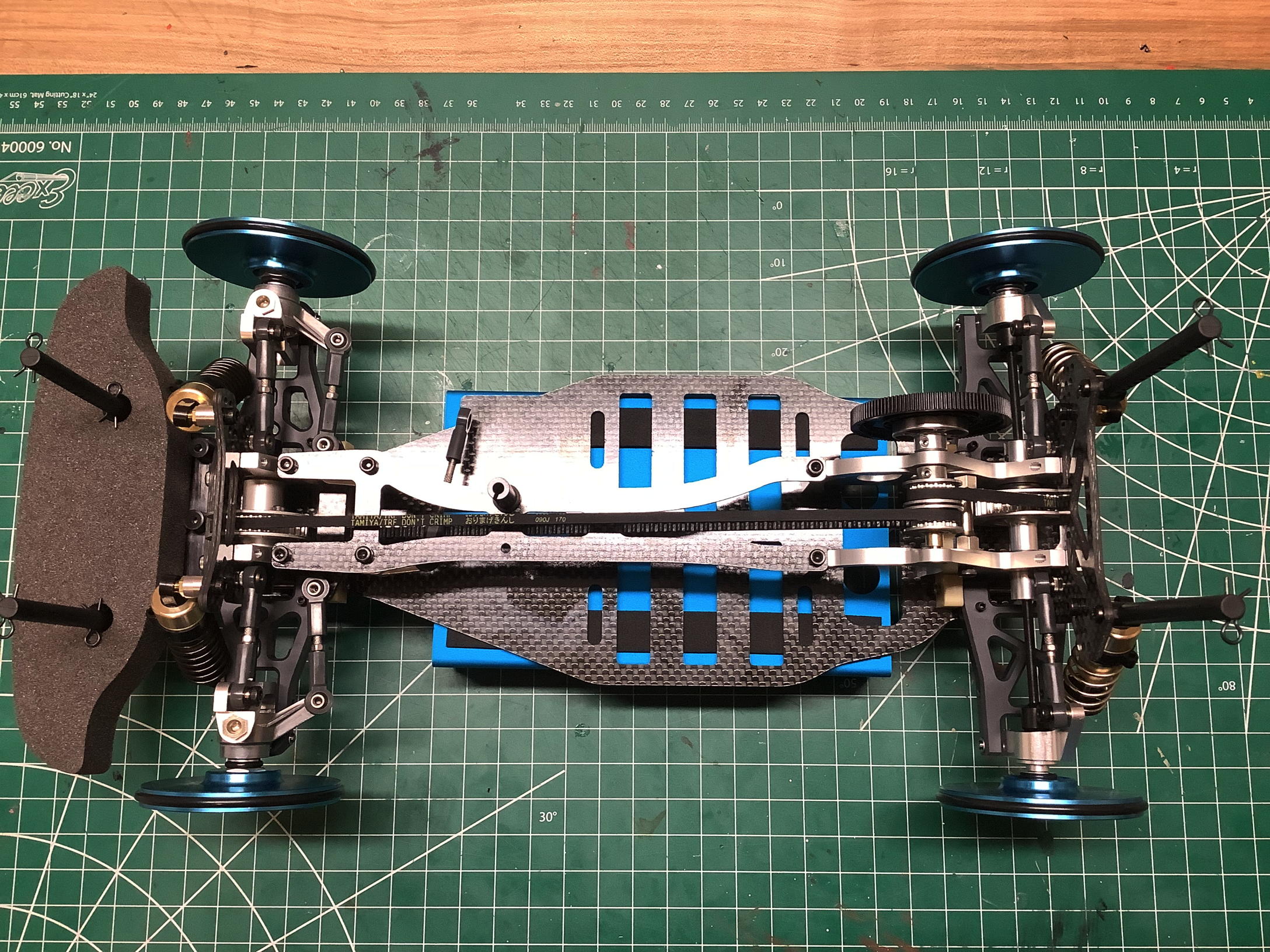
chassis on the table. The pictures above show the chassis from the
side and from above. From the side you can see how much open
space there is, though much of this would be filled by batteries, motor,
servo, ESC, and receiver in a completed read-to-run configuration.
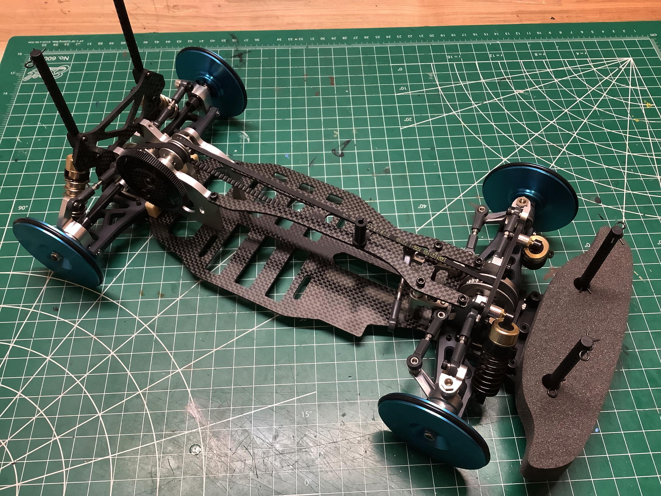
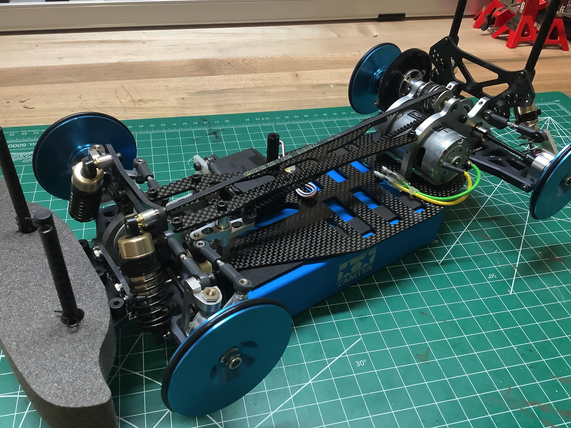
On the left is a final overhead isometric view. On the right I've
installed some basic temporary electronics to "complete" the chassis for
display. I've installed a standard silver can motor despite the
fact the no one in their right mind would ever use such a motor in this
chassis. Paired with the standard 35T pinion, this at least keeps
the chassis from rolling and allows a quick battery connection to see
the wheels spin. The steering servo has no hard mounting which is a
weakness of this chassis. It has to be installed with servo tape.
©2024 Eric Albrecht