Tamiya TRF 419 Project
Page 2: Assembling the Chassis
While writing about this build, I am going to concentrate on the
differences between this and the last chassis in the TRF line I built
(the TRF 418). I also built a TRF 419X
several years ago and wrote about it extensively but without comparison
to any other model. The photos and details are still useful.
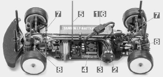
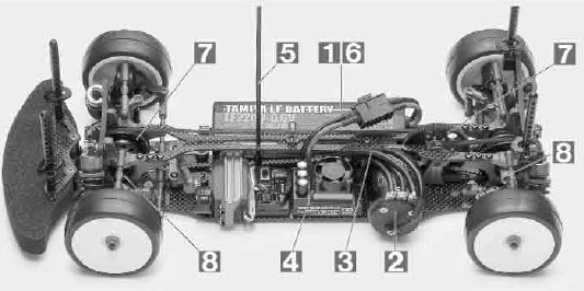
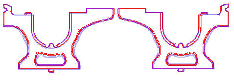
Can you spot the differences between the TRF 418 (left) and the TRF
419 (right)? It's highly unlikely because they are so
externally similar. Not only is the layout the same, many of the parts are
the same including most of the suspension. There are subtle
differences scattered throughout though. Possibly the only
difference a trained eye might spot in the above images is that the
pulleys are now black instead of white.
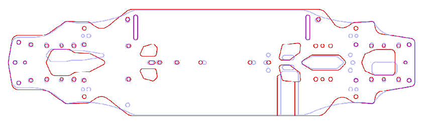
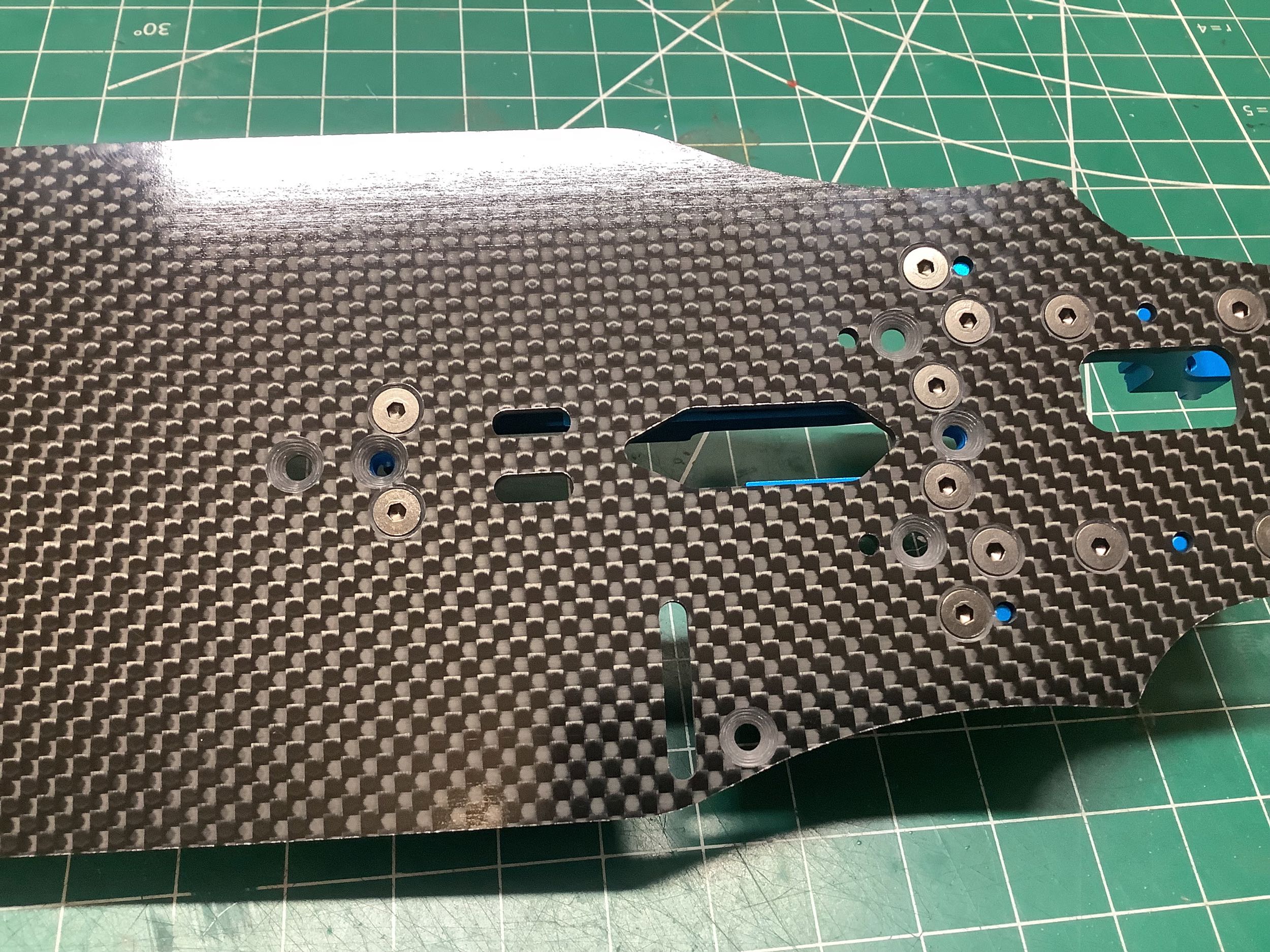
If we compare the TRF 418 lower chassis plate (red) and the one from the
419 (blue), certain changes can be discerned. The biggest
important difference is that the motor has moved slightly aft. The
holes for the bulkheads have also moved slightly further apart (more on
that later), and the cutouts for the pulleys have become smaller.
The previous "relief cuts" which had been added to the TRF 418 as a
stated improvement have now been removed, also stated as an improvement.
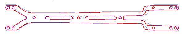
What about the upper deck? It also gets very slight, almost
imperceptible changes which can only be seen by overlaying the
parts. Overall shape and length are unchanged, but the holes for
the bulkheads have been moved slightly apart. The holes for
attachment to the motor mount, which were optional on the TRF 418, have
now been removed entirely.
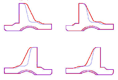
Here are some more slight changes. The lower bulkheads have been
slightly strengthened at the sides with a thicker profile and smaller
lower cutout. The rest of the dimensions appear identical suggesting
that these would
probably be interchangeable between models, so don't get them mixed up
in your parts box or you'll never straighten it out again. The
story is similar with the upper bulkheads which have had slightly more
material removed making them a bit lighter and weaker. It's
interesting that the lower bulkheads got stronger while the upper got
weaker. This probably cancels out any weight change.
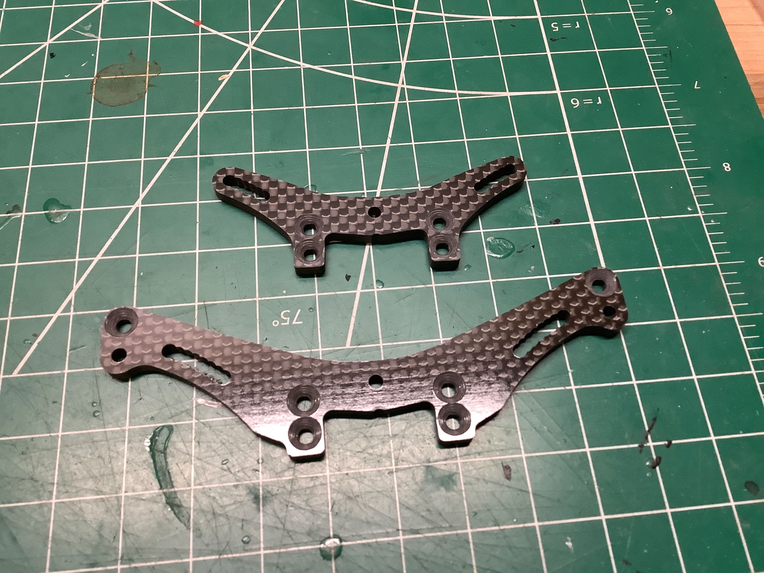
The shock towers have identical outer dimensions and shock attachment
positions, but the bulkhead mounting holes have moved very slightly
further apart. In this case they would not easily fit on the TRF
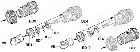
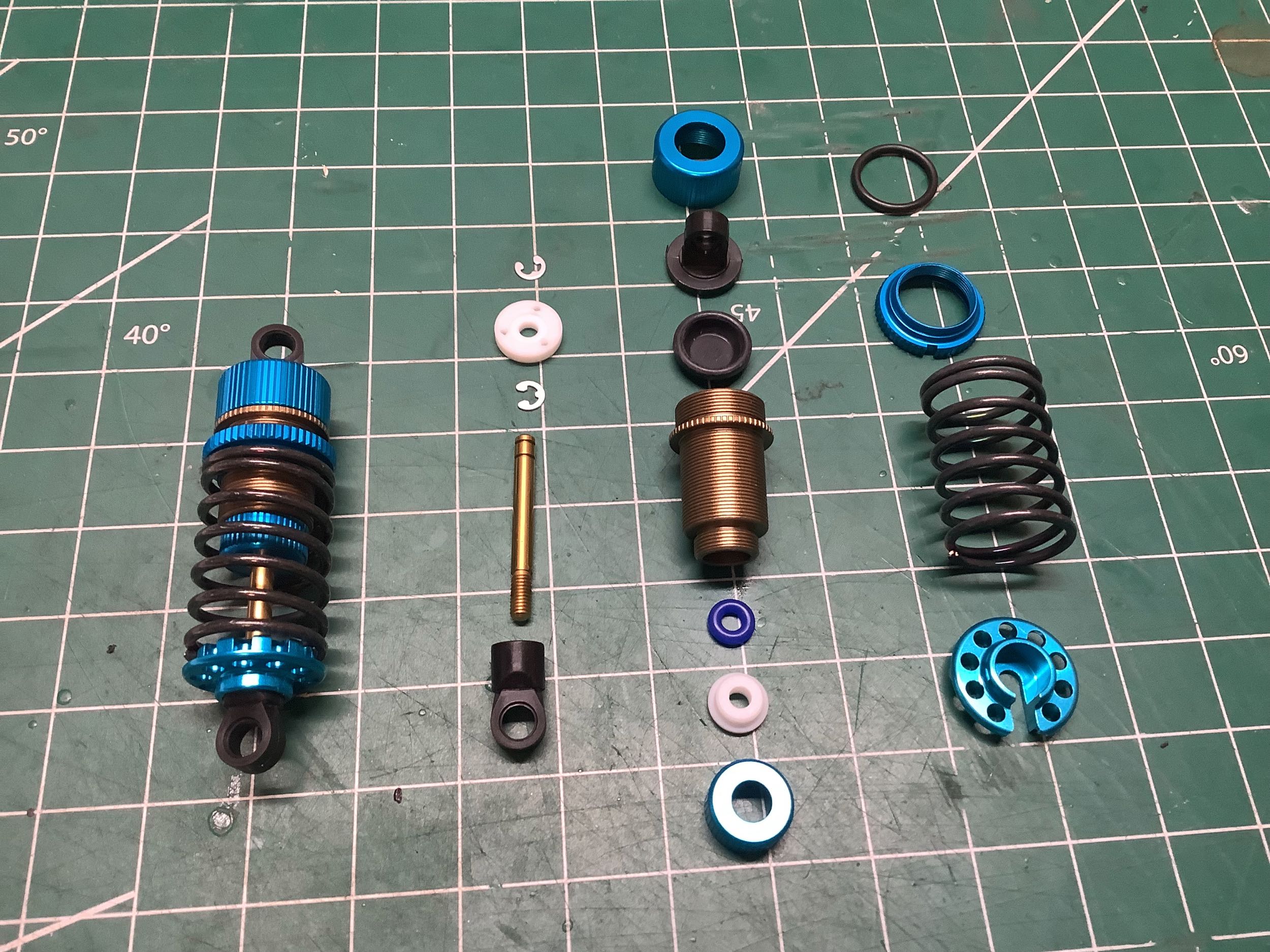
418 without forcing them. The dampers themselves have even changed
by a sneaky amount. The TRF 418 (and prior models) used an
o-ring (BD8), a shaft guide (BD5), and a rod guide (BD4). Now the
TRF 419 eliminates the shaft guide and uses a longer rod guide (BD4)
instead. The rod cap, cylinder cap, and spring retainers stay the same,
but the cylinder is slightly changed to accommodate the new sealing
system. Much less obvious is the fact that the internal diameter
of the
cylinder has increased by 0.5mm increasing the fluid volume by about
10%. The only external change (which can be seen by looking
closely at the picture) is the addition of knurling to the outer rim of
the cylinder which makes it possible to visually distinguish the
versions. More about this when I build the dampers below.
Note that the TRF 419X moved to an even bigger bore for the dampers
(+1.2mm) which means that these intermediate diameter dampers seem to
have only been used for a single model (although they were available separately as 42287 and are still available [with strengthened V-parts] as 42354).
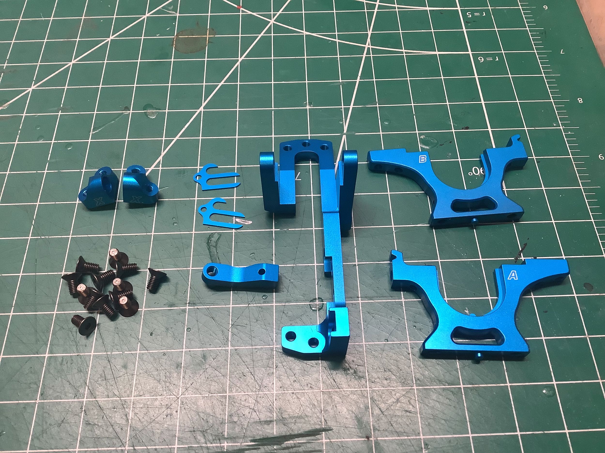
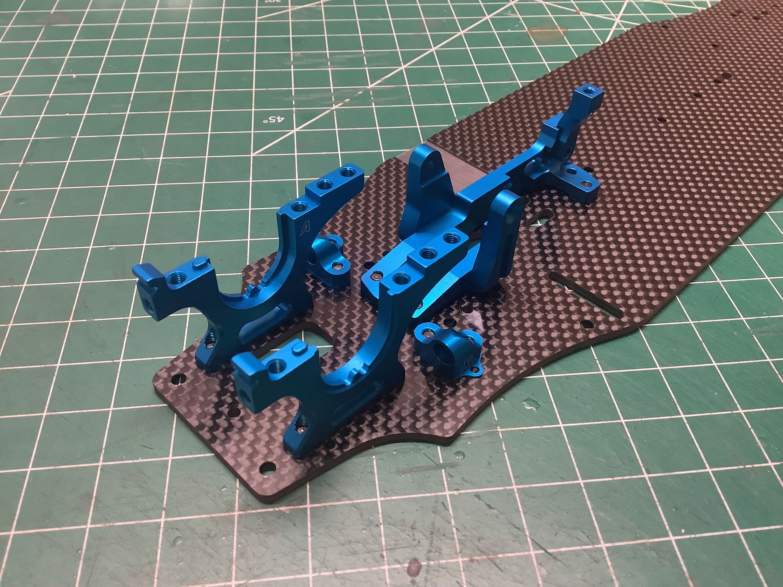
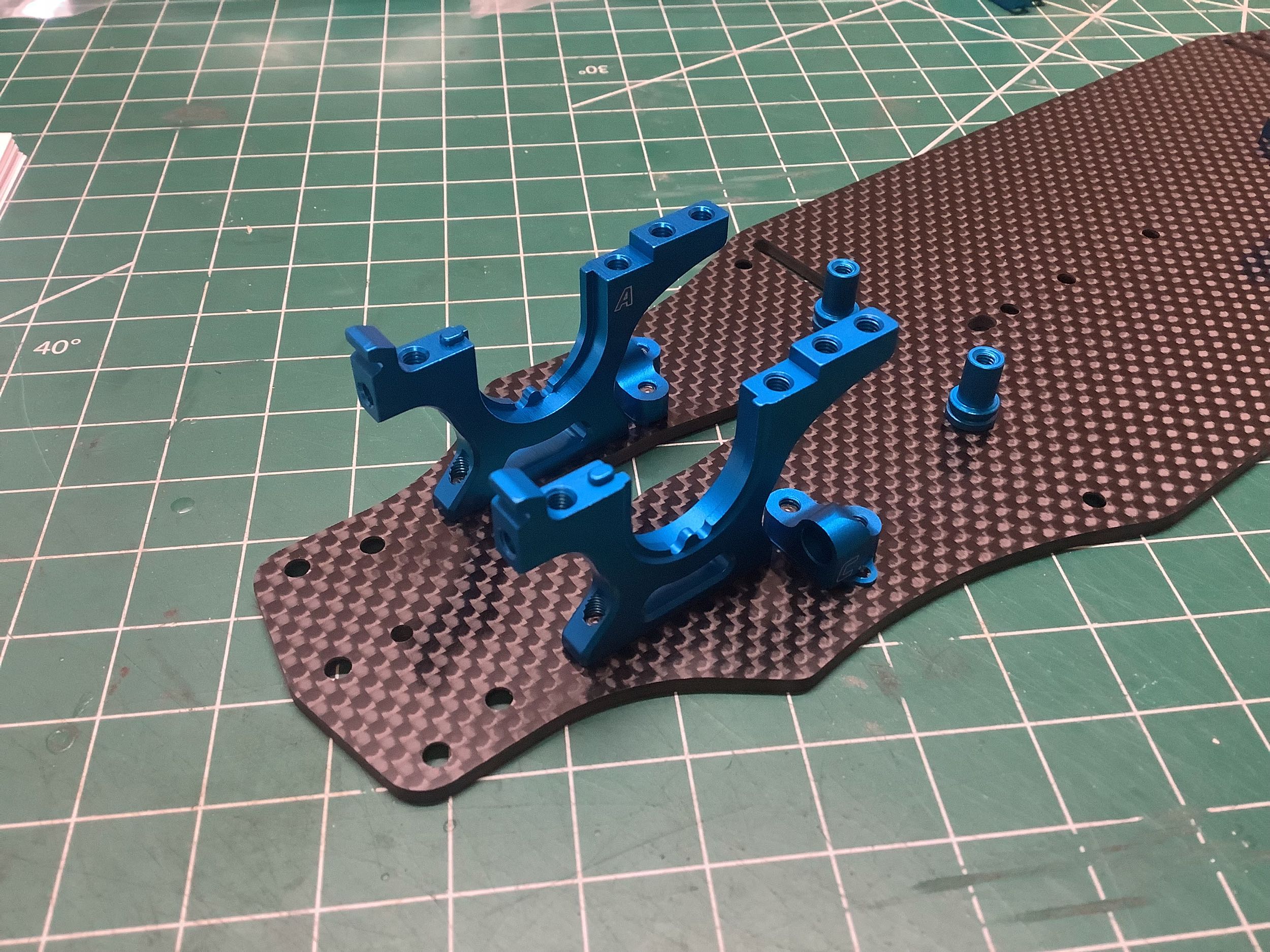
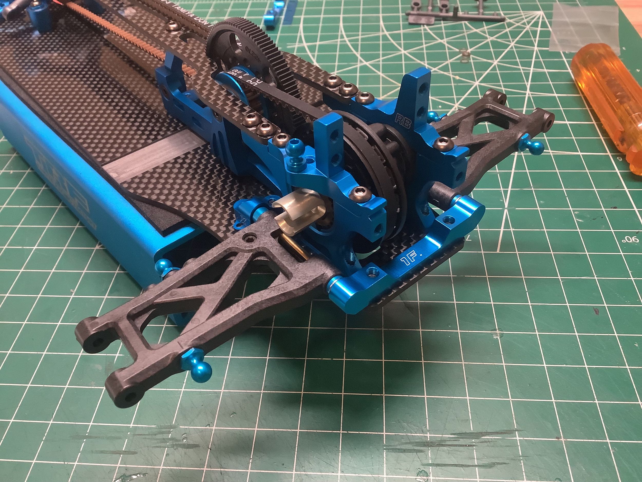
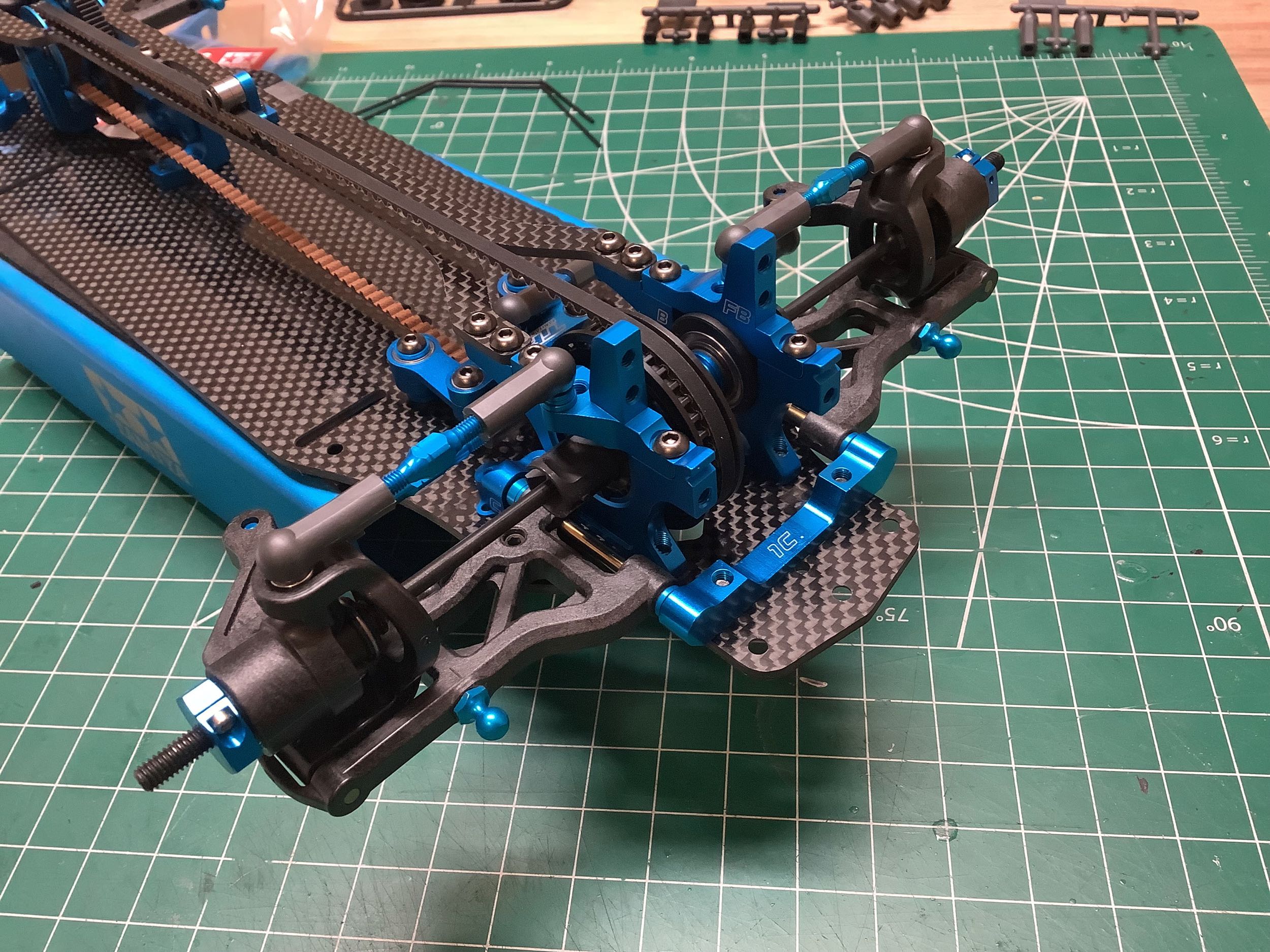
The build begins with the rear bulkheads, center bulkheads, and motor
mount. As previously discussed, the rear bulkheads are extremely
similar to those from the TRF 418 but very slightly strengthened.
The extremely complex 2-piece motor mount serves to also support the
center shaft and will now only accommodates brushless motors with 6
mounting holes (more on that later). This was replaced with a more
complex to assemble, but simpler to manufacture 3-piece motor mount on
the TRF 419X and an even simpler version on the XR. The split
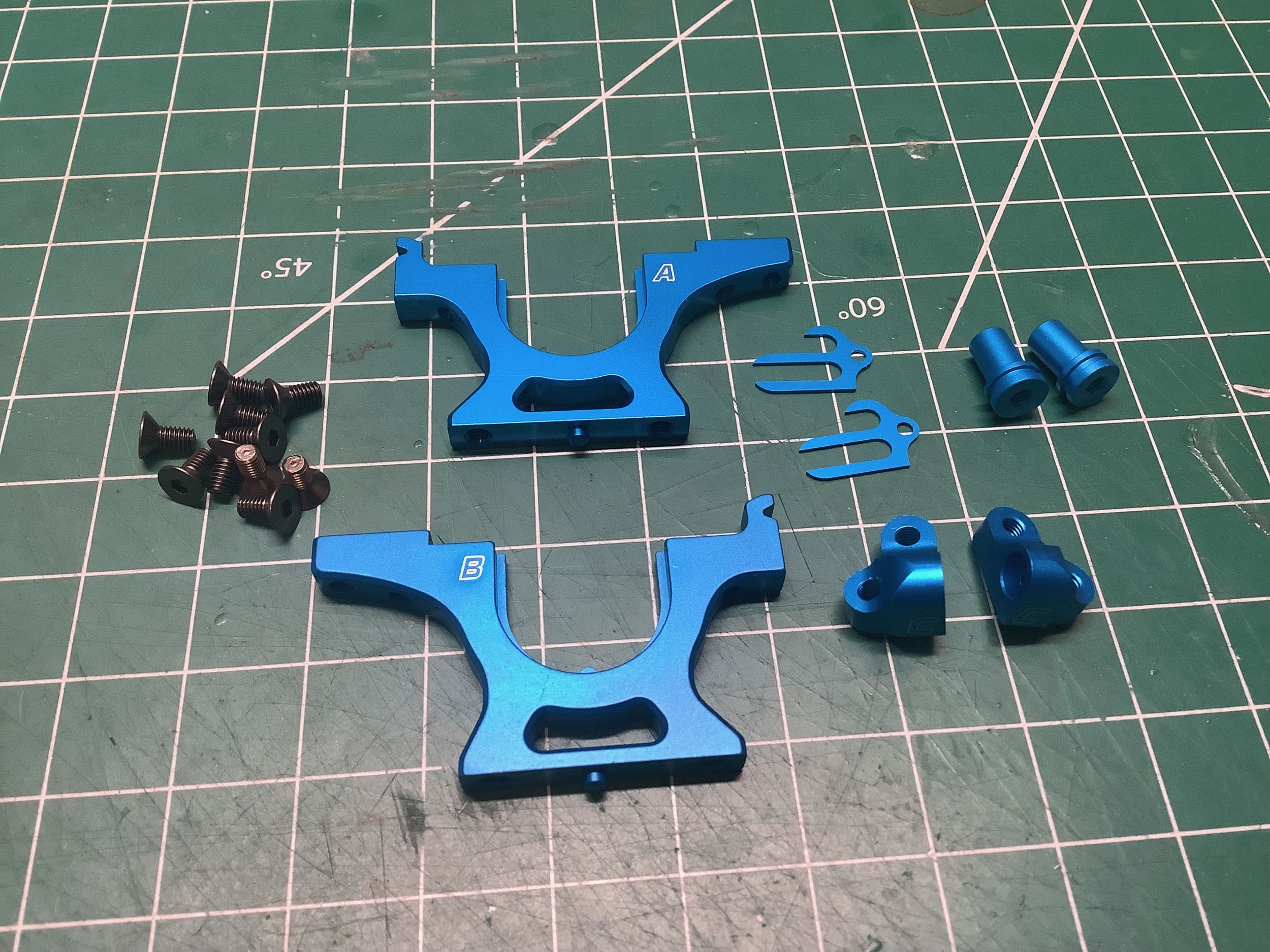
suspension mounts from the TRF 418 have been updated to a "corner"
style. Whereas the previous versions were reversible resulting in
two spacing options with a single set of parts, these are unique and
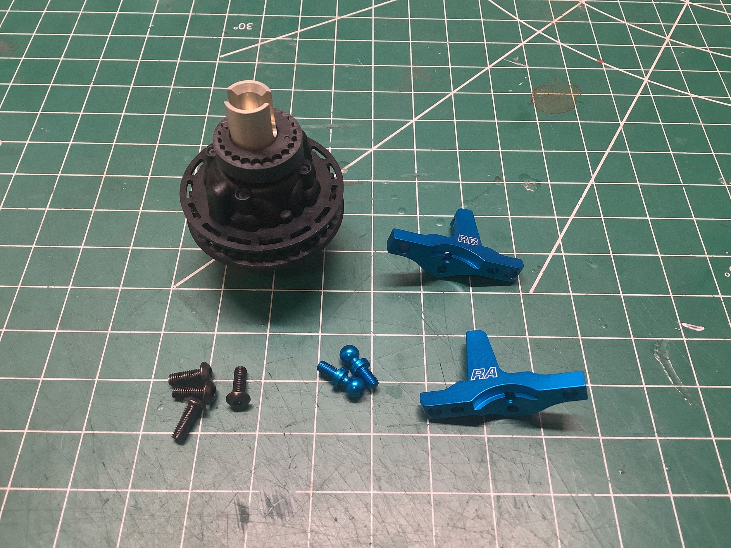
must be replaced for different spacing. This model uses blocks 1X
for the rear suspension. Those little trident looking parts are
spacers that go under the suspension mounts to change the roll center.
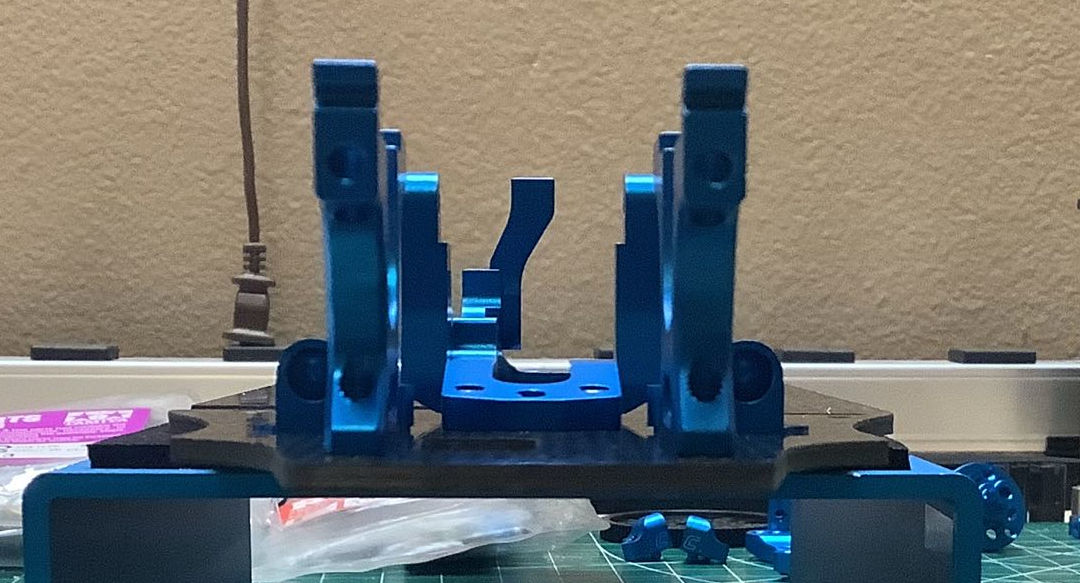
This aft view on the left was intended to show the new split suspension
blocks but they are difficult to see. The bottom view on the right
shows that there are 3 mounting holes at each end of the motor
mount. By default only the outer 2 are used, but the inner hole
can be used instead to reduce chassis stiffness. To maximize
stiffness, all 3 can be filled (which is what I ended up doing after
this photo was taken).
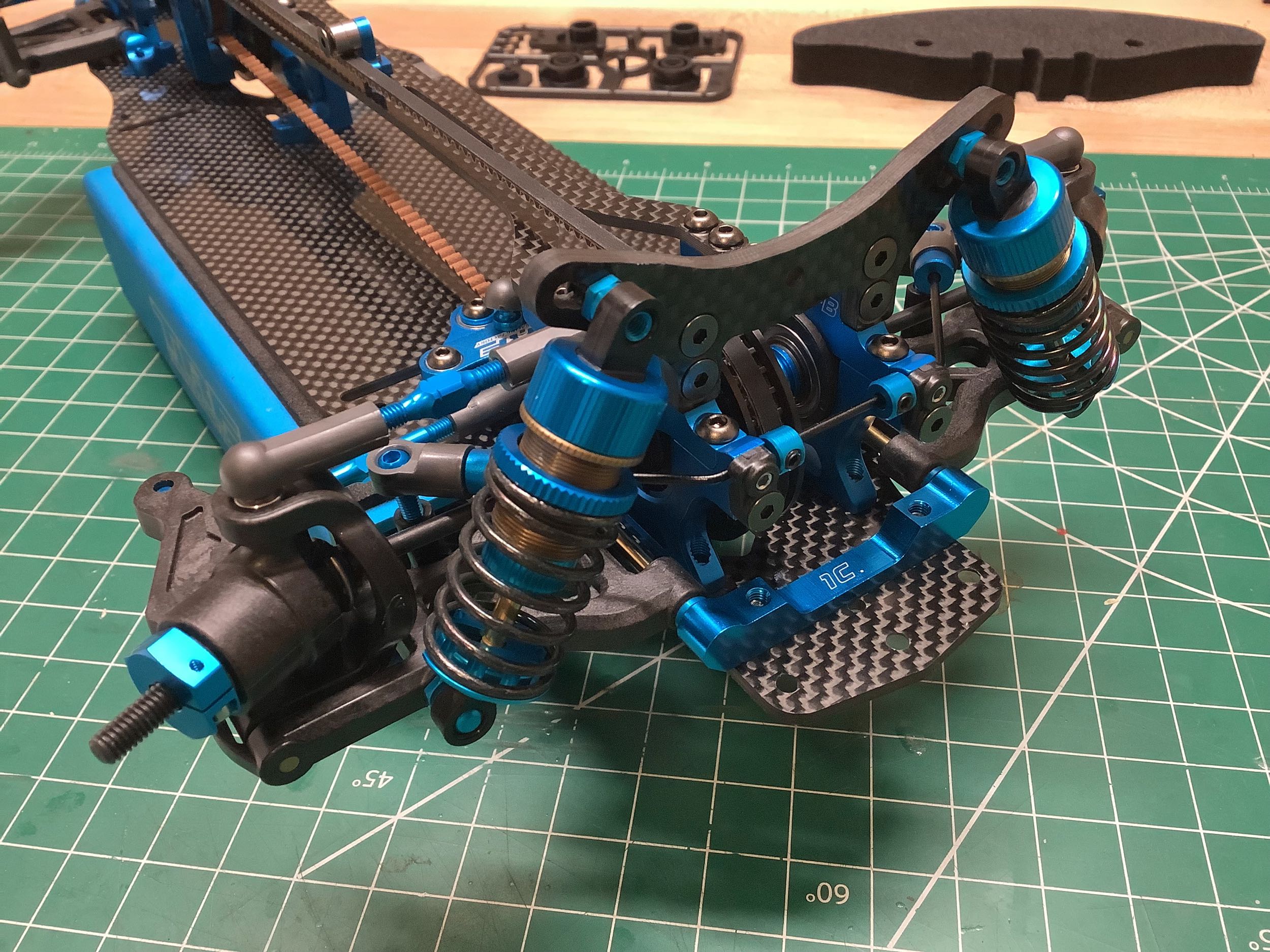
The front bulkheads are exactly the same as those in the rear. The
front suspension blocks work the same as those in the rear but they are
1C instead of 1X (narrower width). The steering posts are
unchanged from the TRF 418.
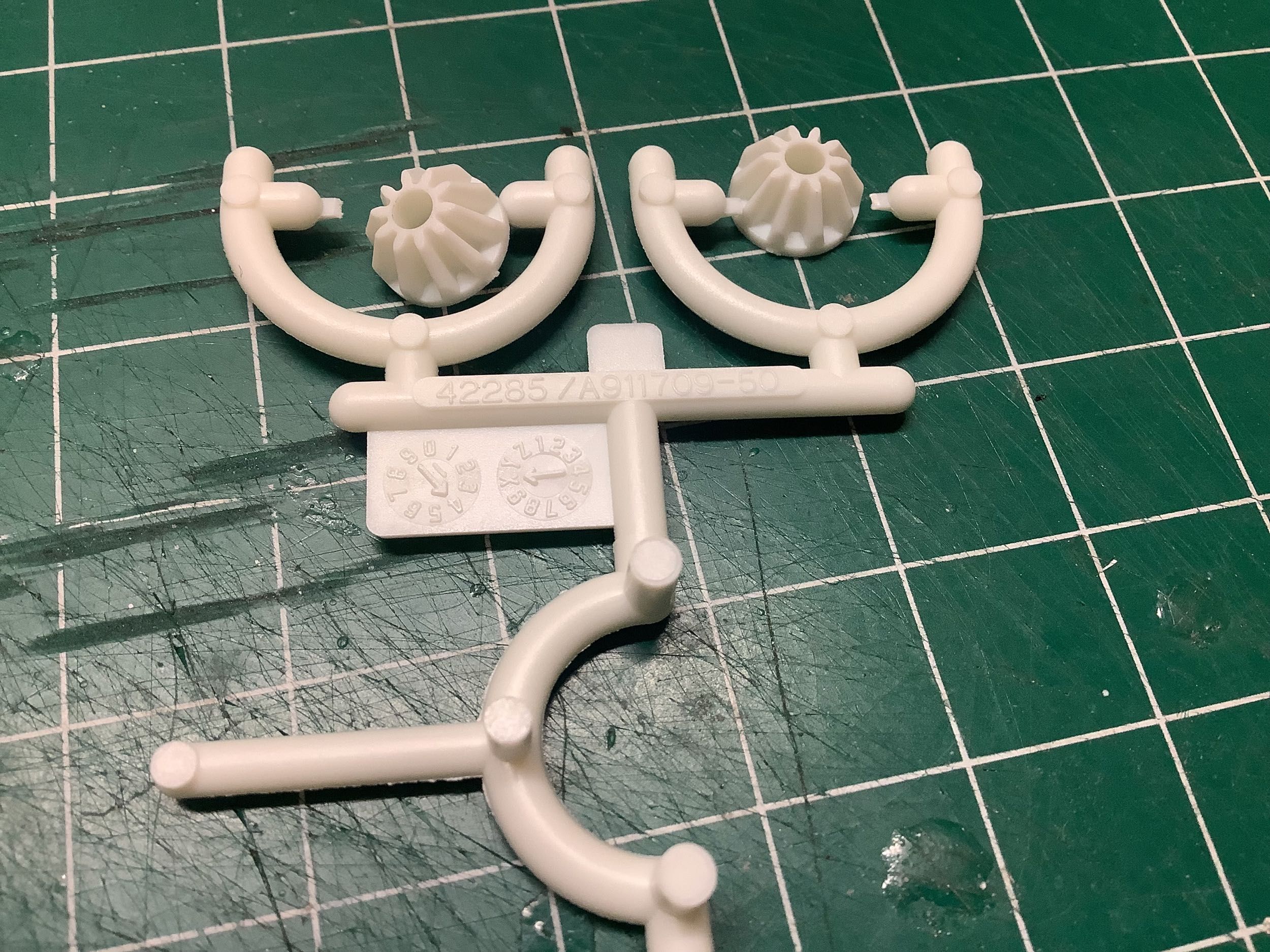
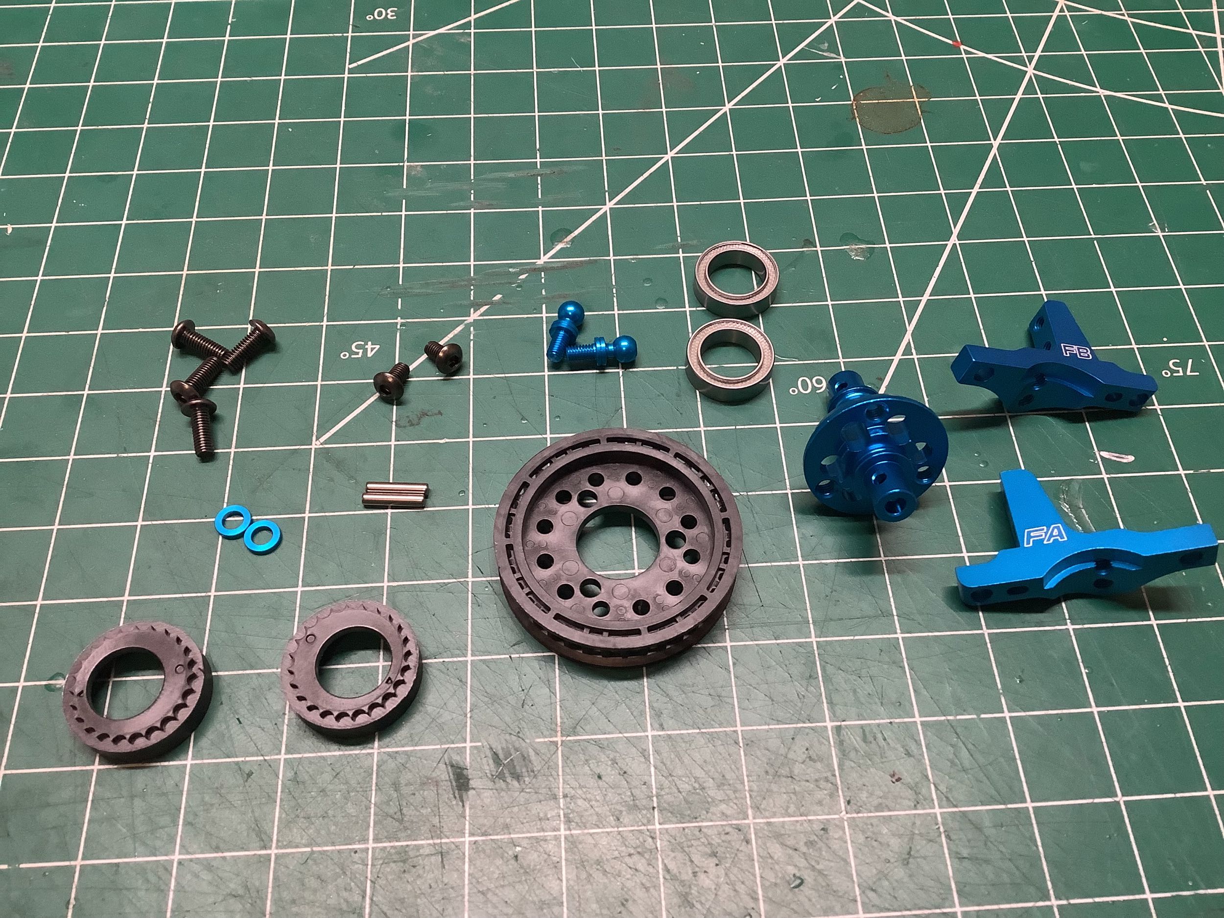
The sealed gear differential represents an interesting color
inversion. Beginning with the TA-06 (and the TRF 417X), sealed
gear differentials used black carbon filled Nylon gears and a white
Delrin housing. These white gears (left) are stamped with 42285
which means they are new for the TRF 420. Delrin isn't as strong
as carbon filled Nylon but is probably more durable. It's not just
the material that has changed, the gear geometry has been reinforced as
well. The housing, on the other hand, has changed to black.
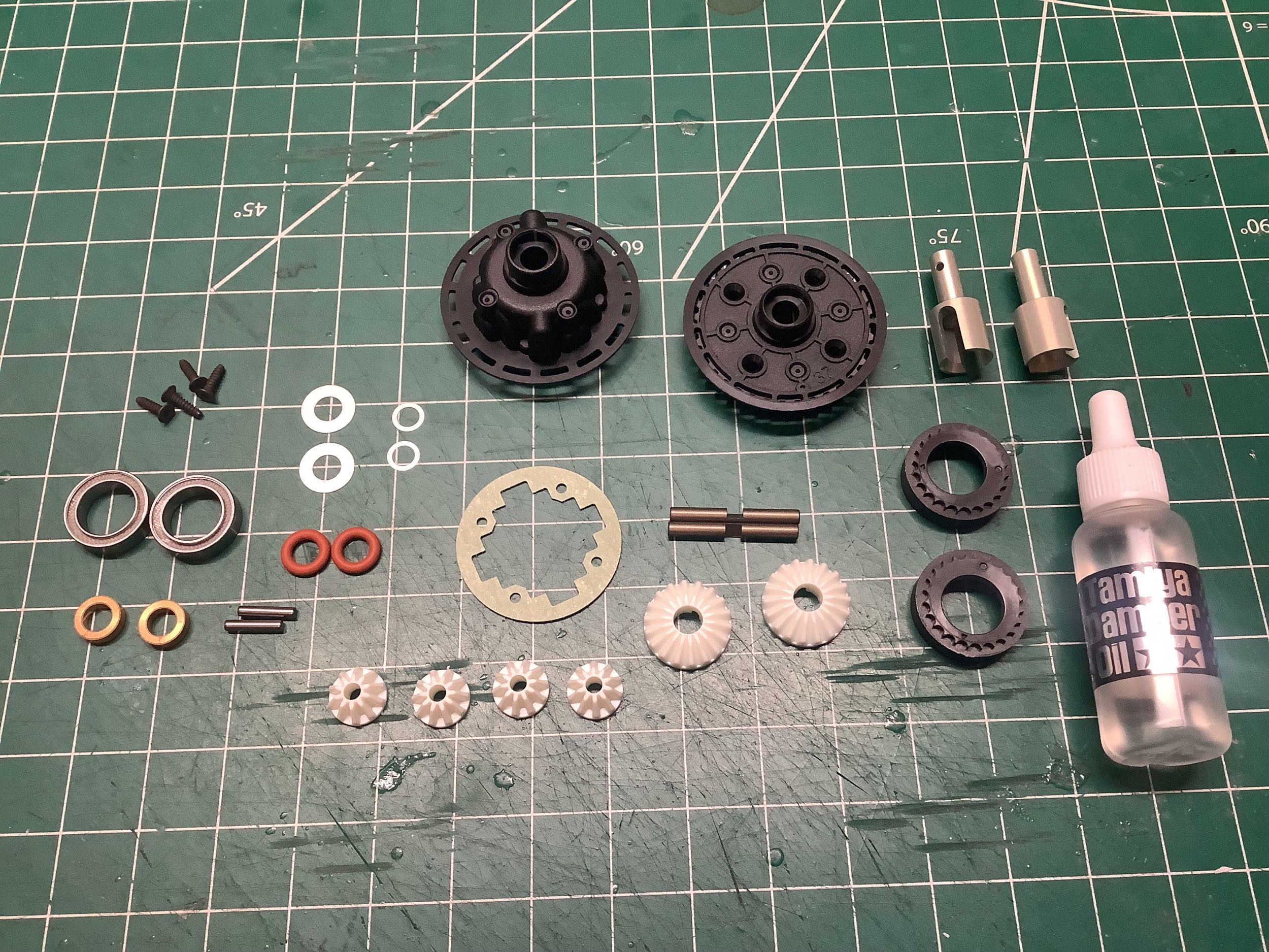
Apart from the obvious color difference, there are some other
changes. The previous gear differentials had no centering support
for the drive cups other than the housing itself. Now oilite
bushings have been added (right) which should last much longer and
provide more sturdy support. Note that the drive cups should only
be rotating within the housing when there is differential action (one
axle is rotating faster than the other, such as in a tight turn) which
is probably why bearings were not used Another hidden change is
that there is now a slot inside the housing giving access for installing
the pin through the drive cup which makes them much easier to assemble. Finally, there is also more oil volume inside the new housing.
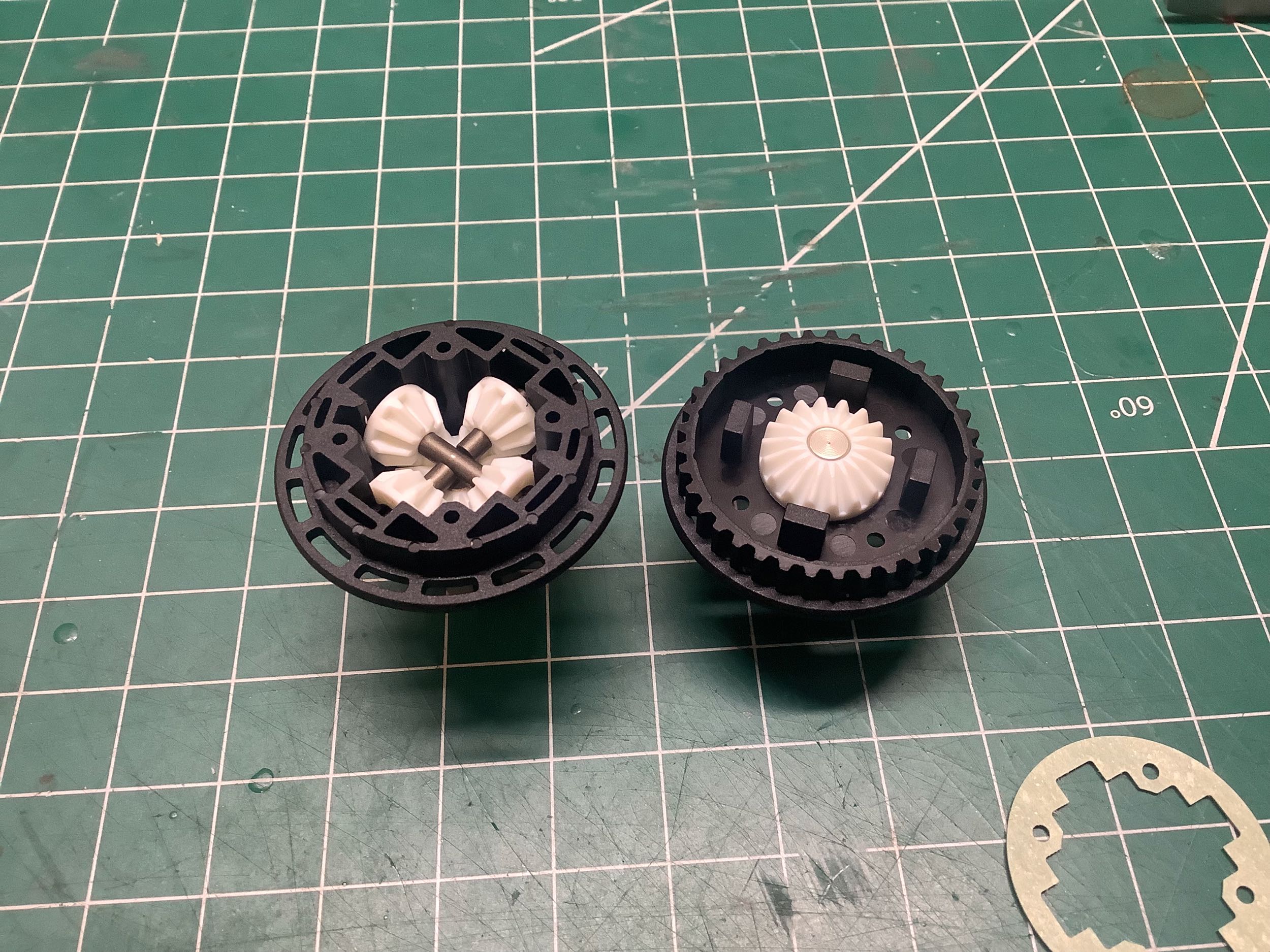
Here's the differential mostly assembled before the #900 weight oil has
been added. If you look closely at the picture on the left you can
see the extra slot located 45° out of phase with the spider gears which
is used for installing the pin. The drive cups are aluminum.
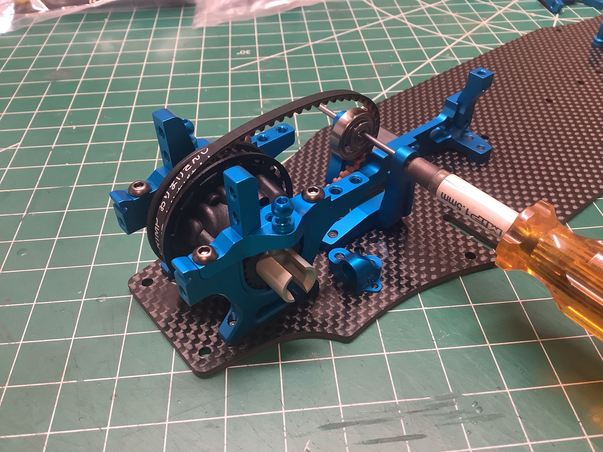
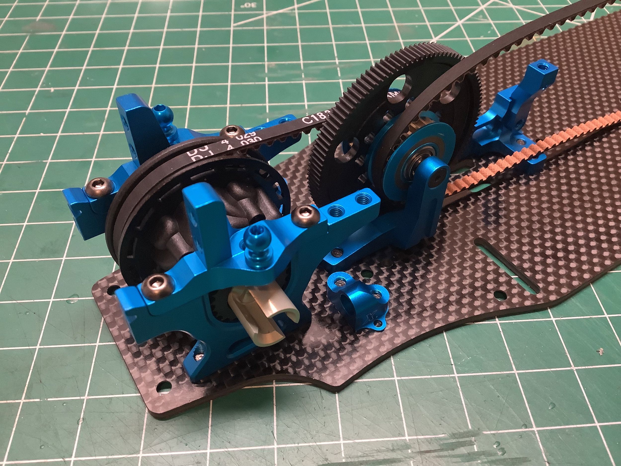
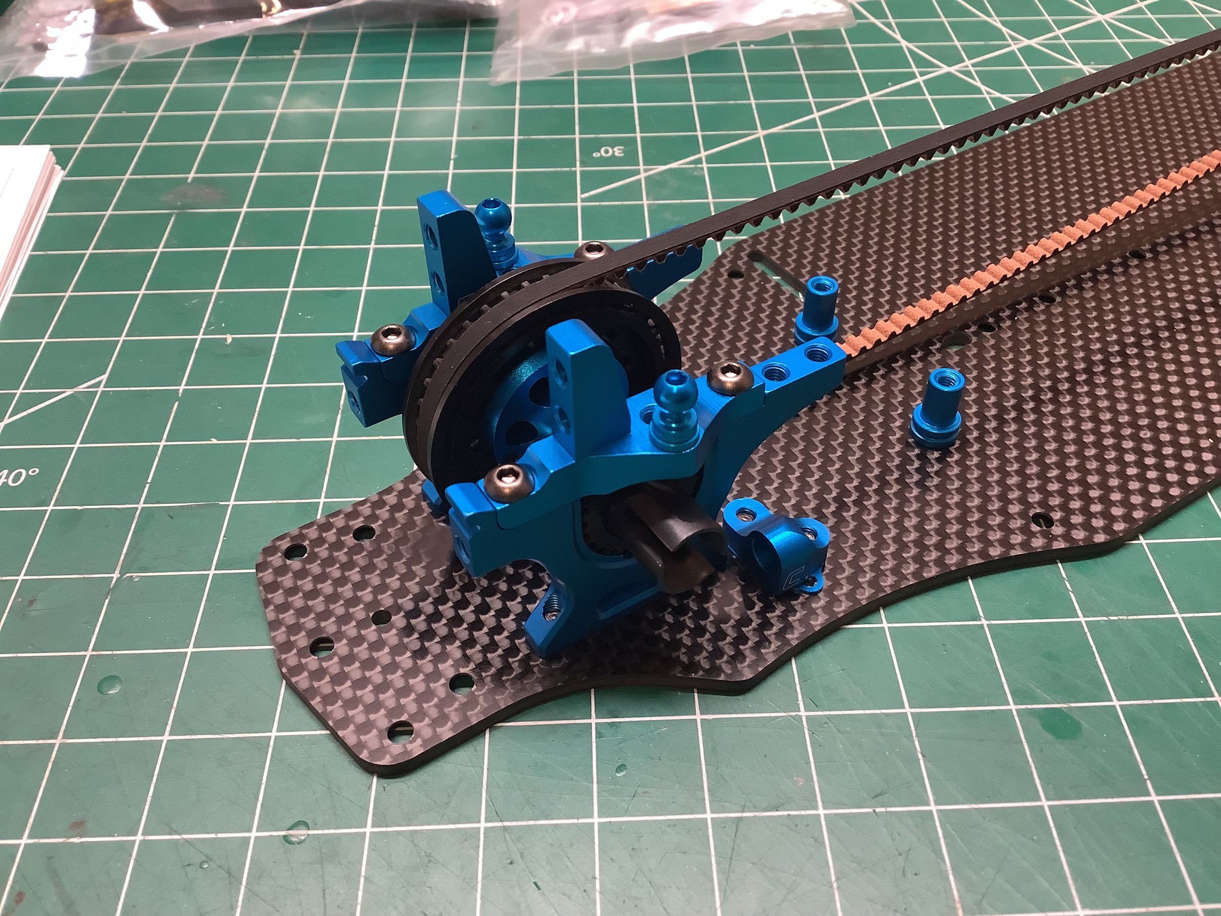
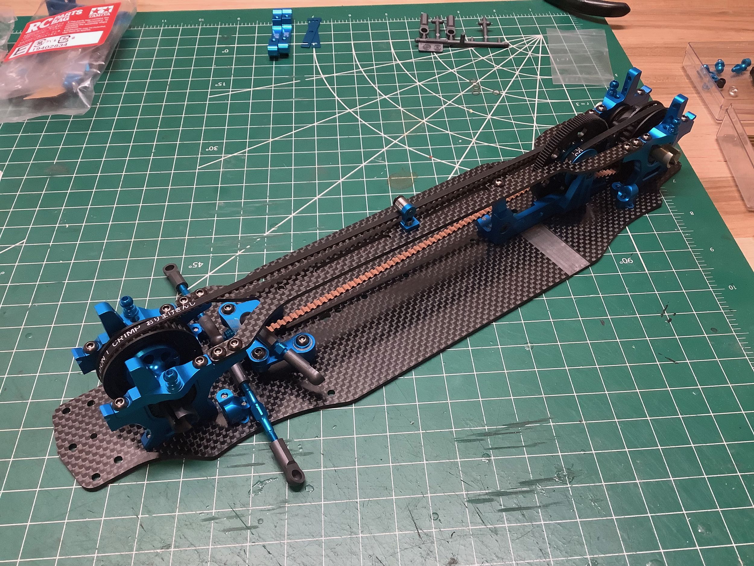
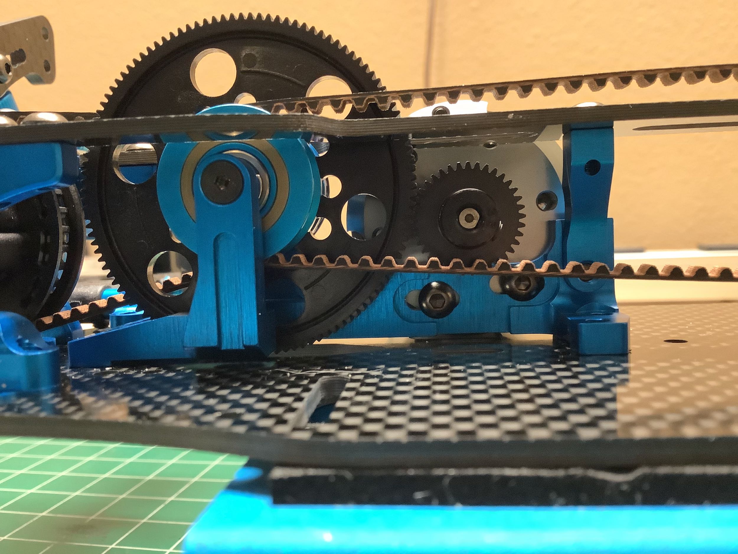
Now the rear differential, belt, and upper bulkheads have been
installed. I'm using a tool to hold the belt in place until the
center shaft is built and installed.
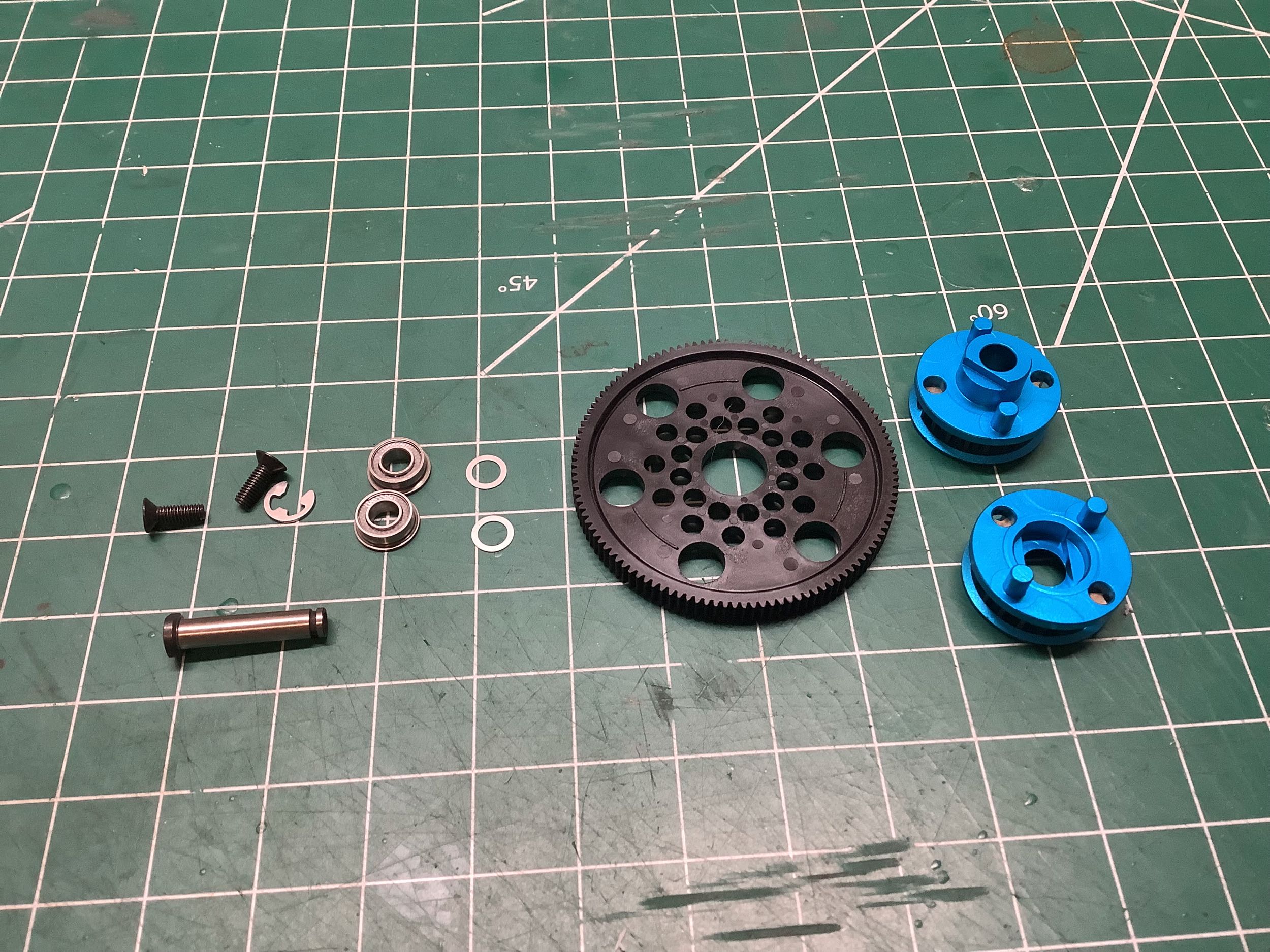
The TRF 419 uses the same 116T spur gear and 20T center pulleys as the
TRF 418. The only difference here is that there are no holes to
attach the upper deck directly above the center shaft this time.
Like the rear pulley, the front pulley has changed from white to
black. The aluminum locked spool is carried over from
the TRF 418, but the steel drive cups have changed to have narrower
slots since the axle caps have been (surprisingly) eliminated from the
front axles.
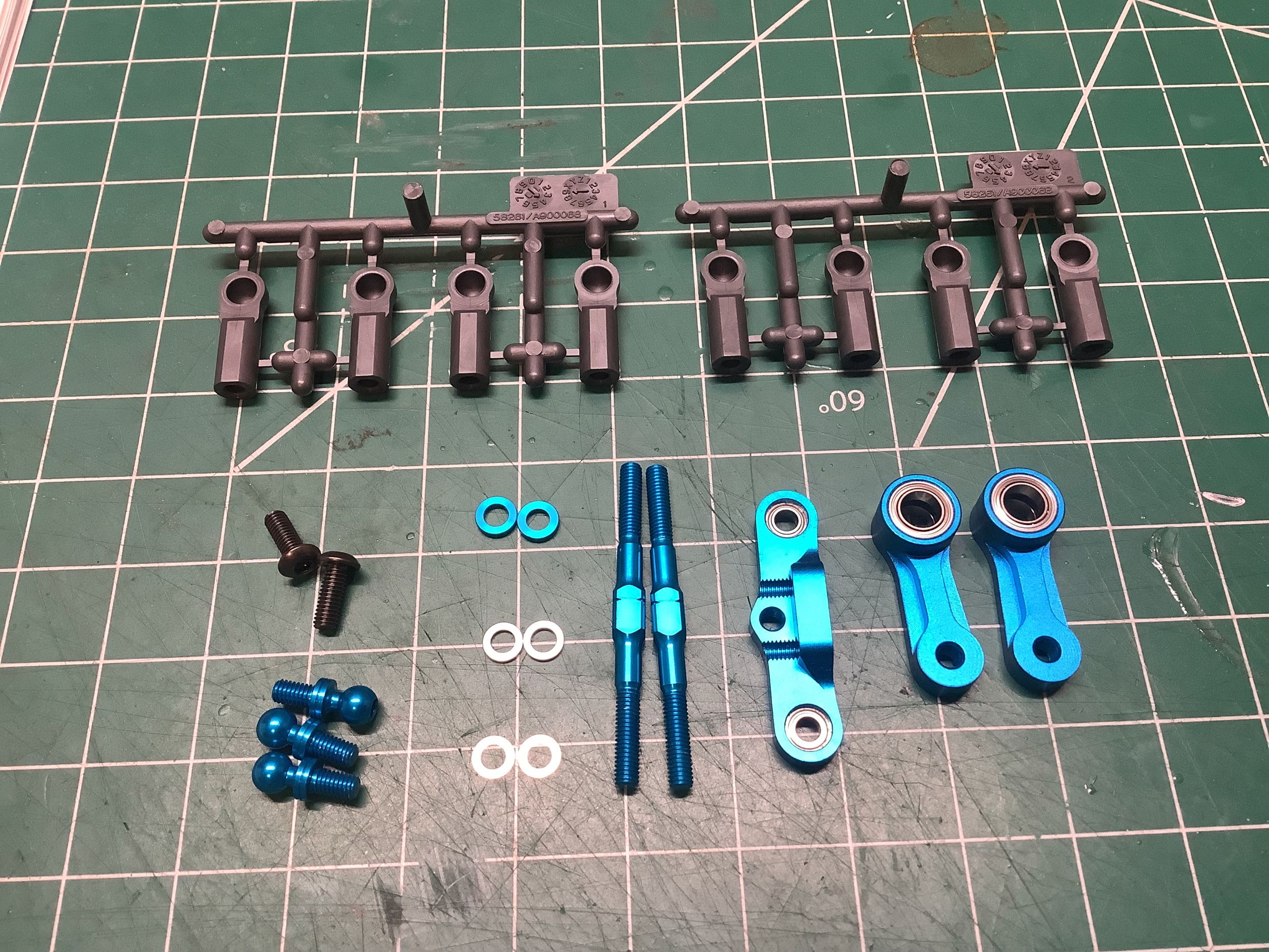
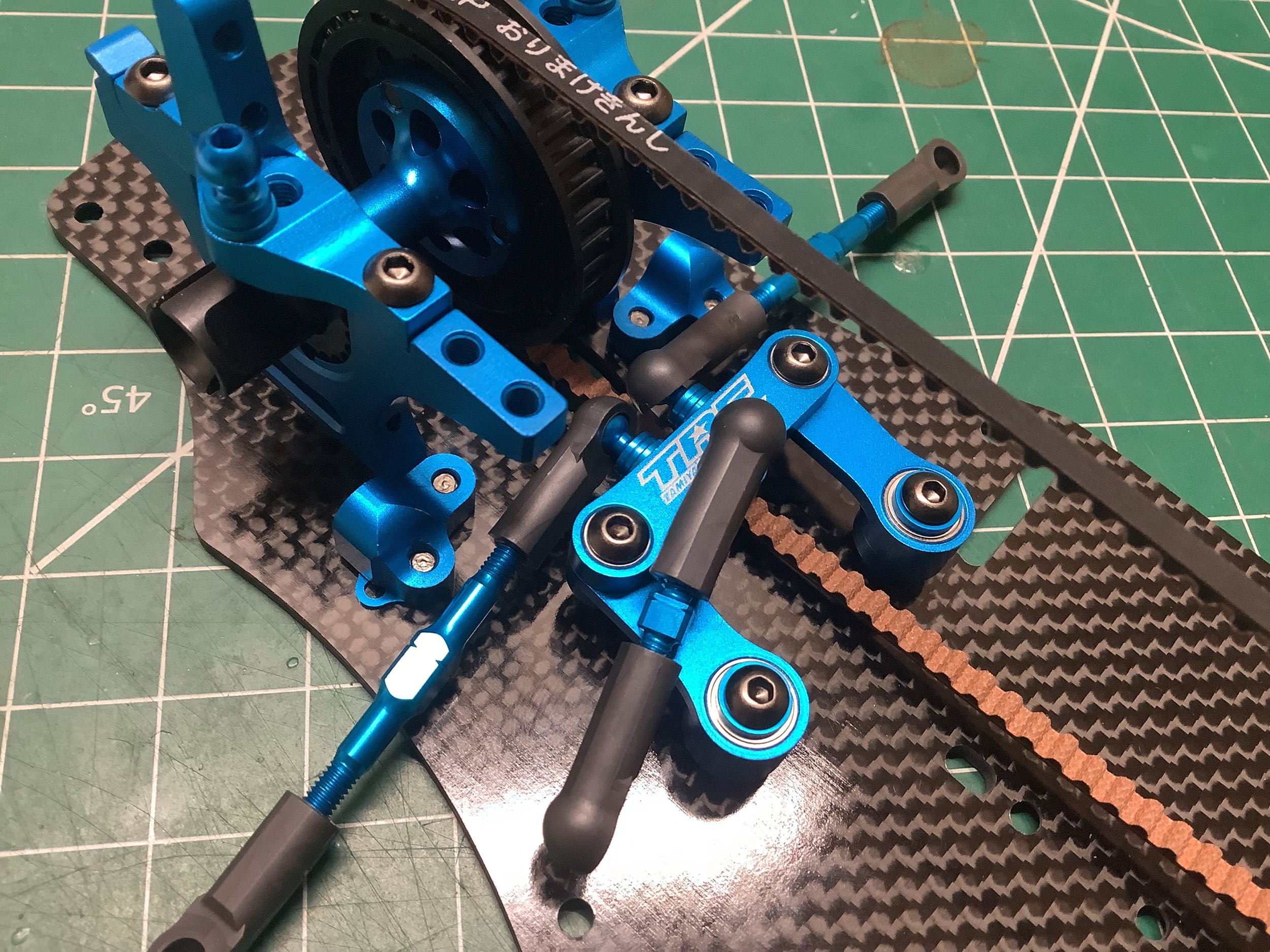
The steering cranks, bridge, and turnbuckles are unchanged from the TRF
418 and everything fits just as tightly and works just as smoothly as
ever.
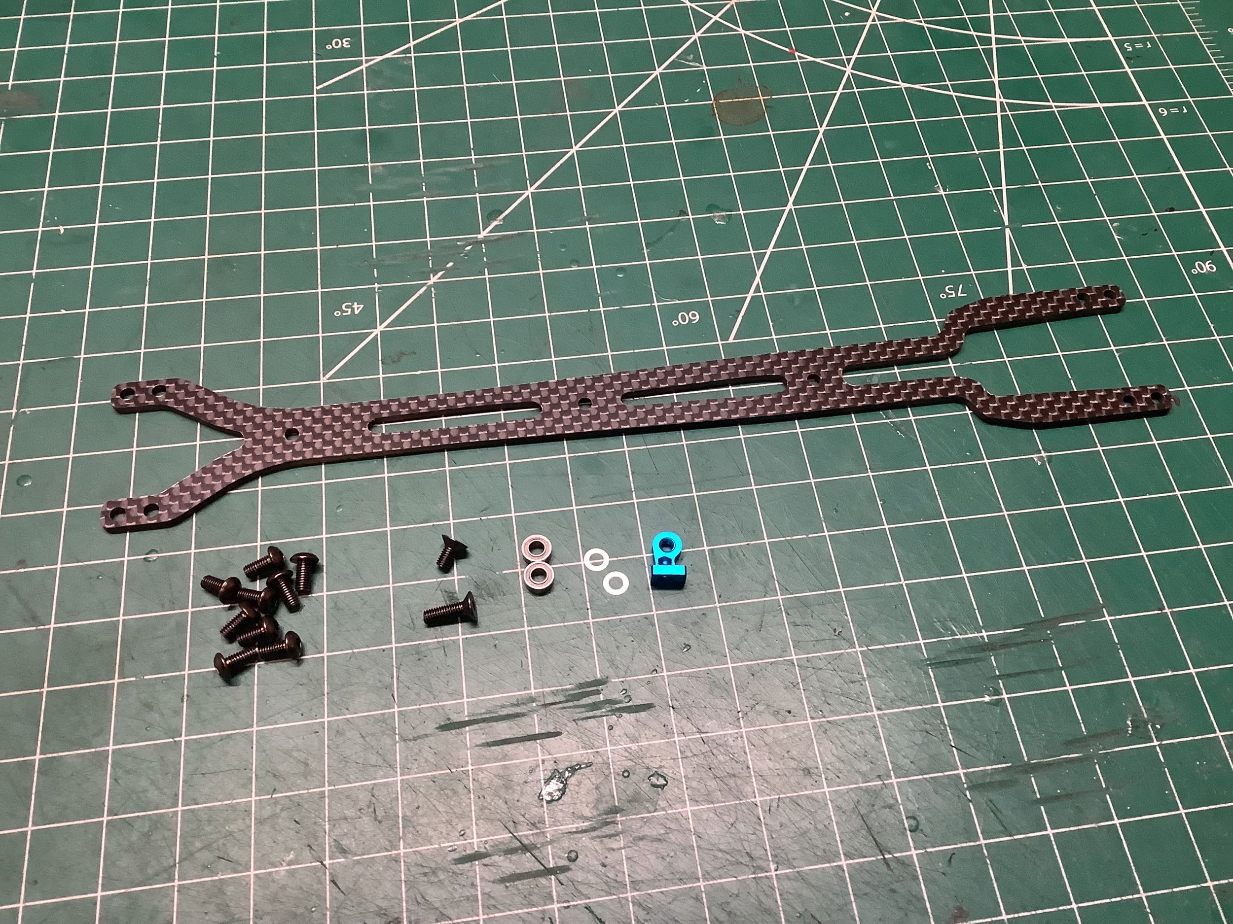
Now we can attach the upper deck which incorporates a bearing to tension
the front belt. There is an extra hole near the front of the
upper deck that leads to nothing. It's not for optional stiffening
because there is nothing to connect it to.
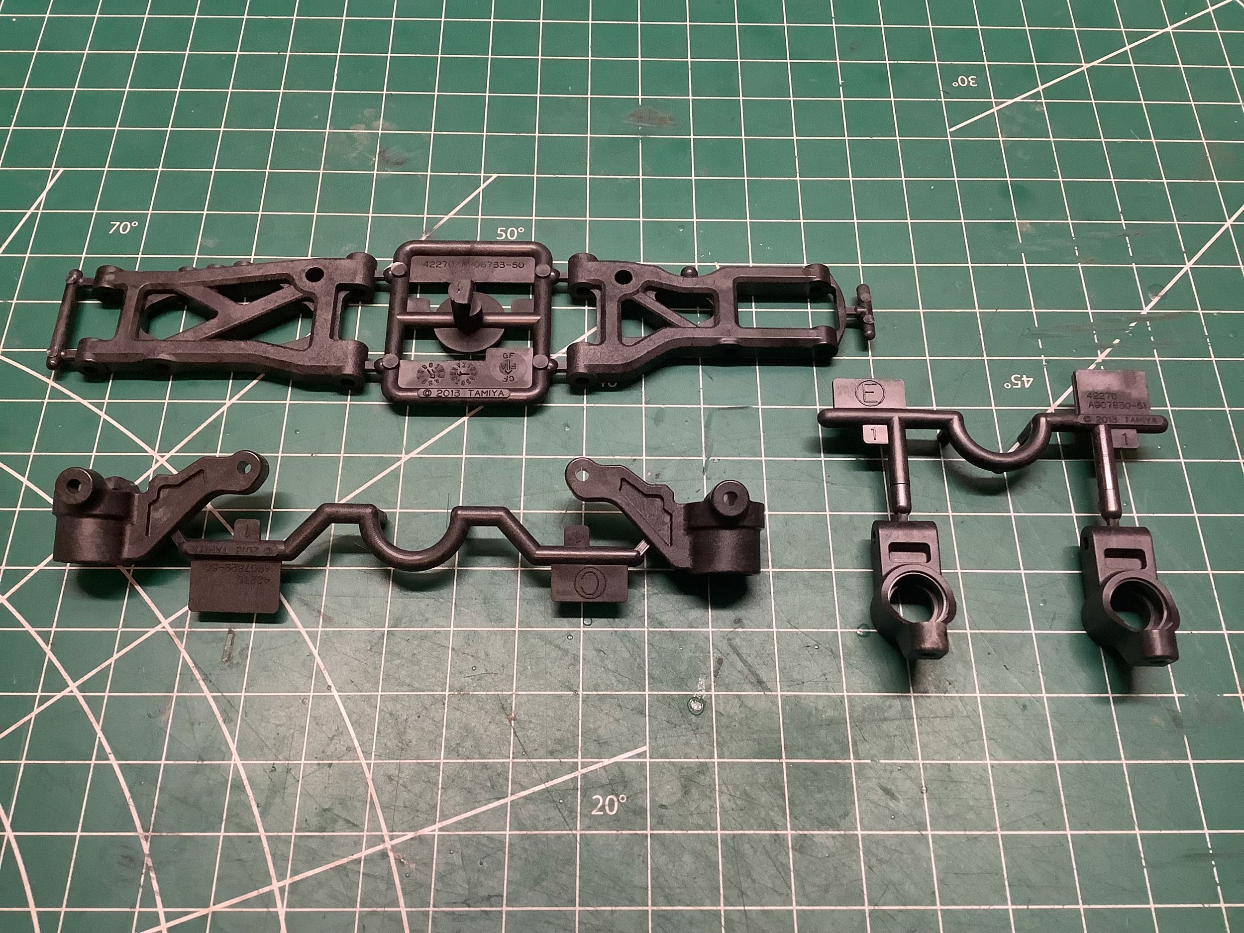
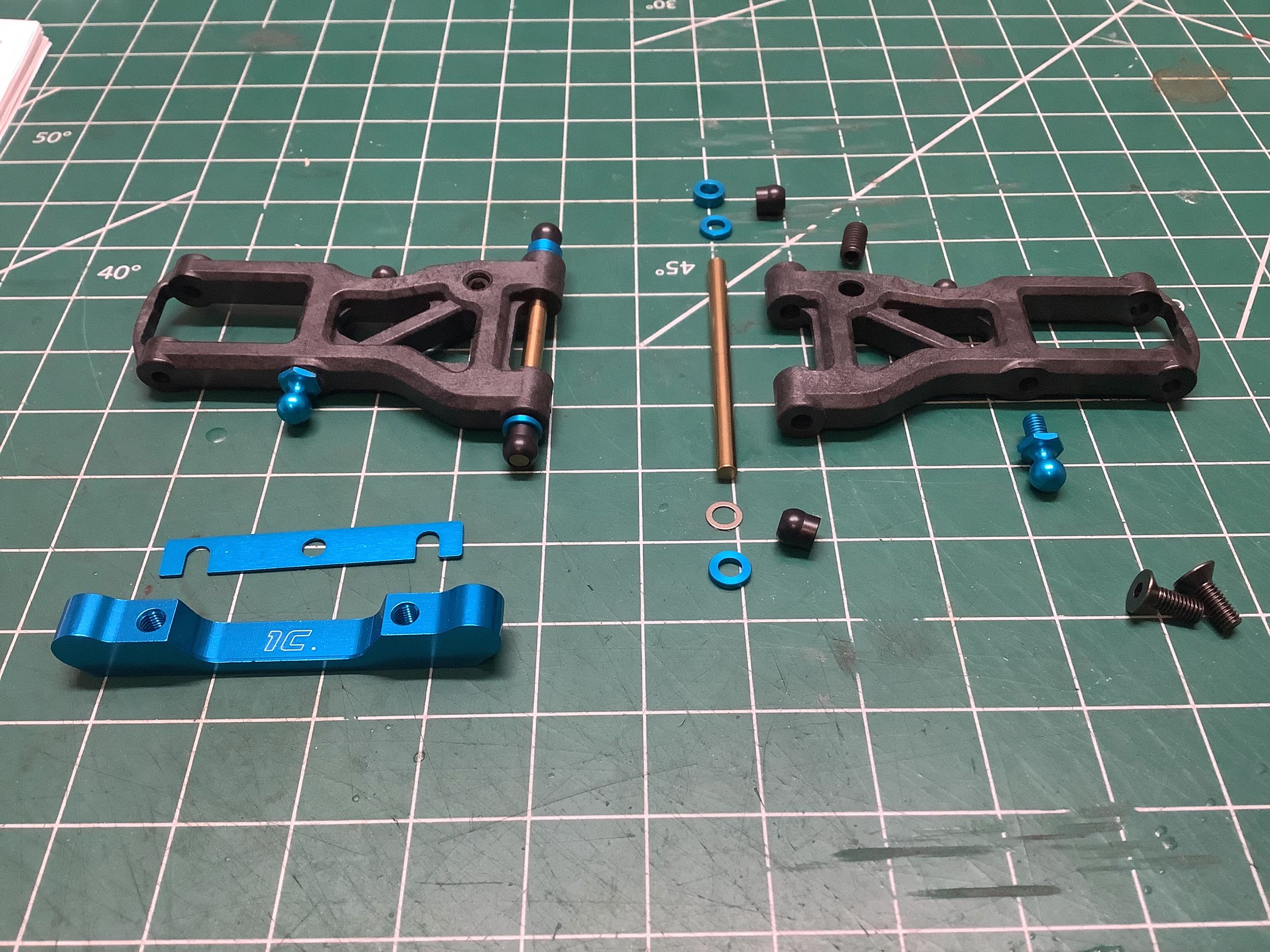
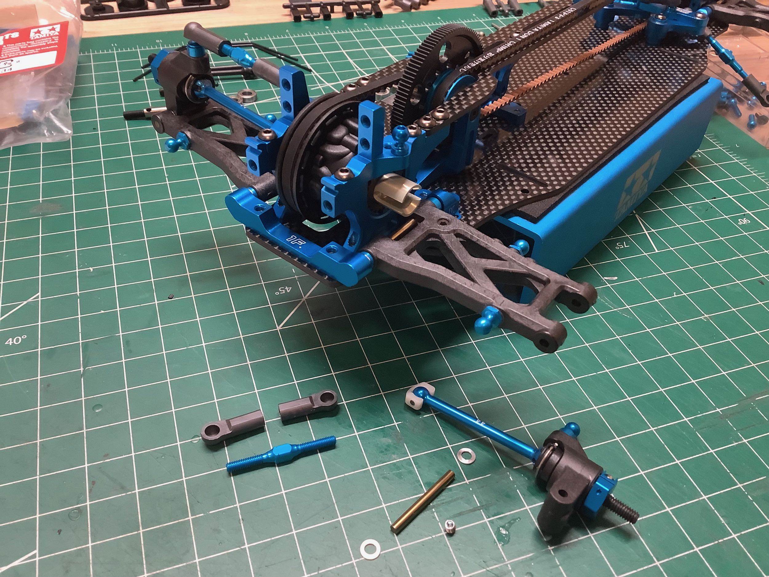
The suspension arms, steering knuckles, and rear uprights are all reused
from the TRF 418. The suspension arms have changed a lot over the years, so it is actually unusual to see them reused.
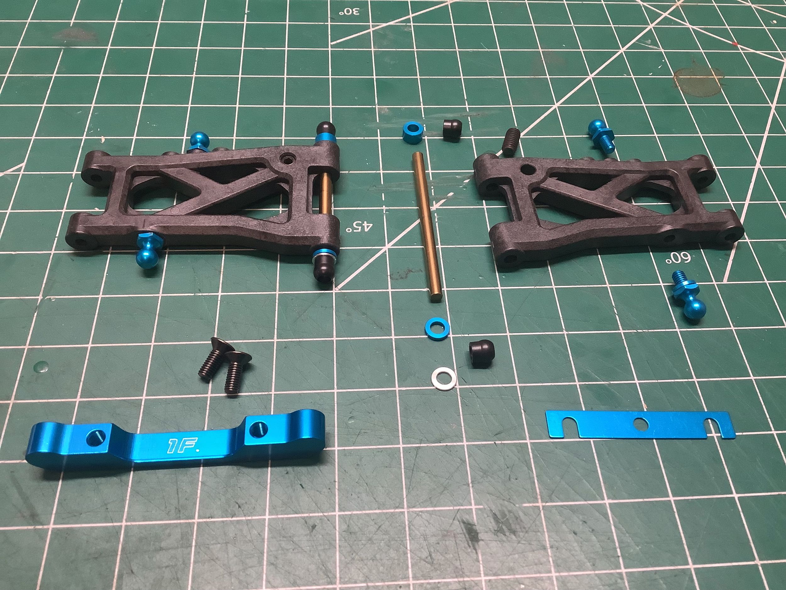
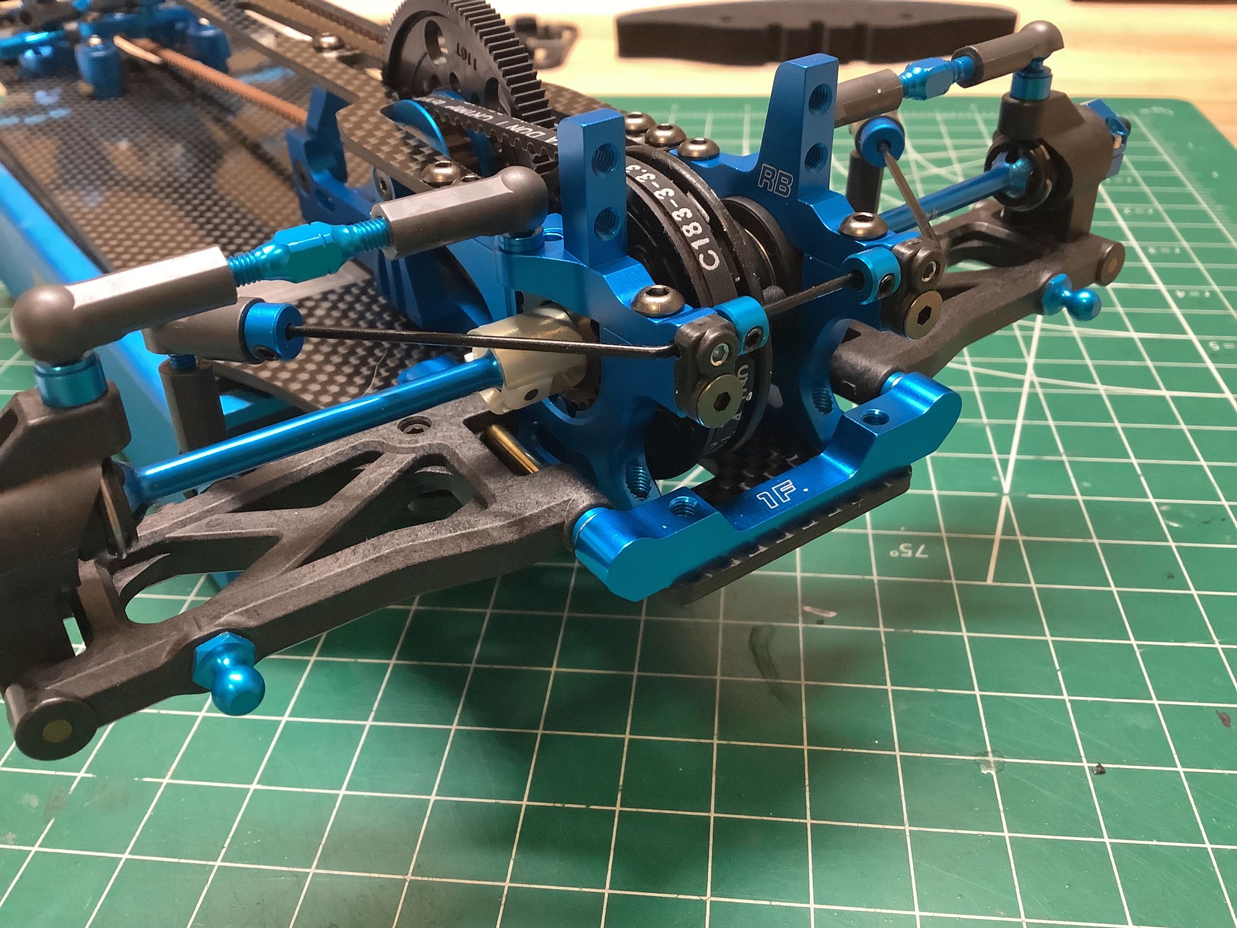
The assembly of the rear suspension is almost exactly like the TRF 418
except that the hinge pins now have a low friction titanium
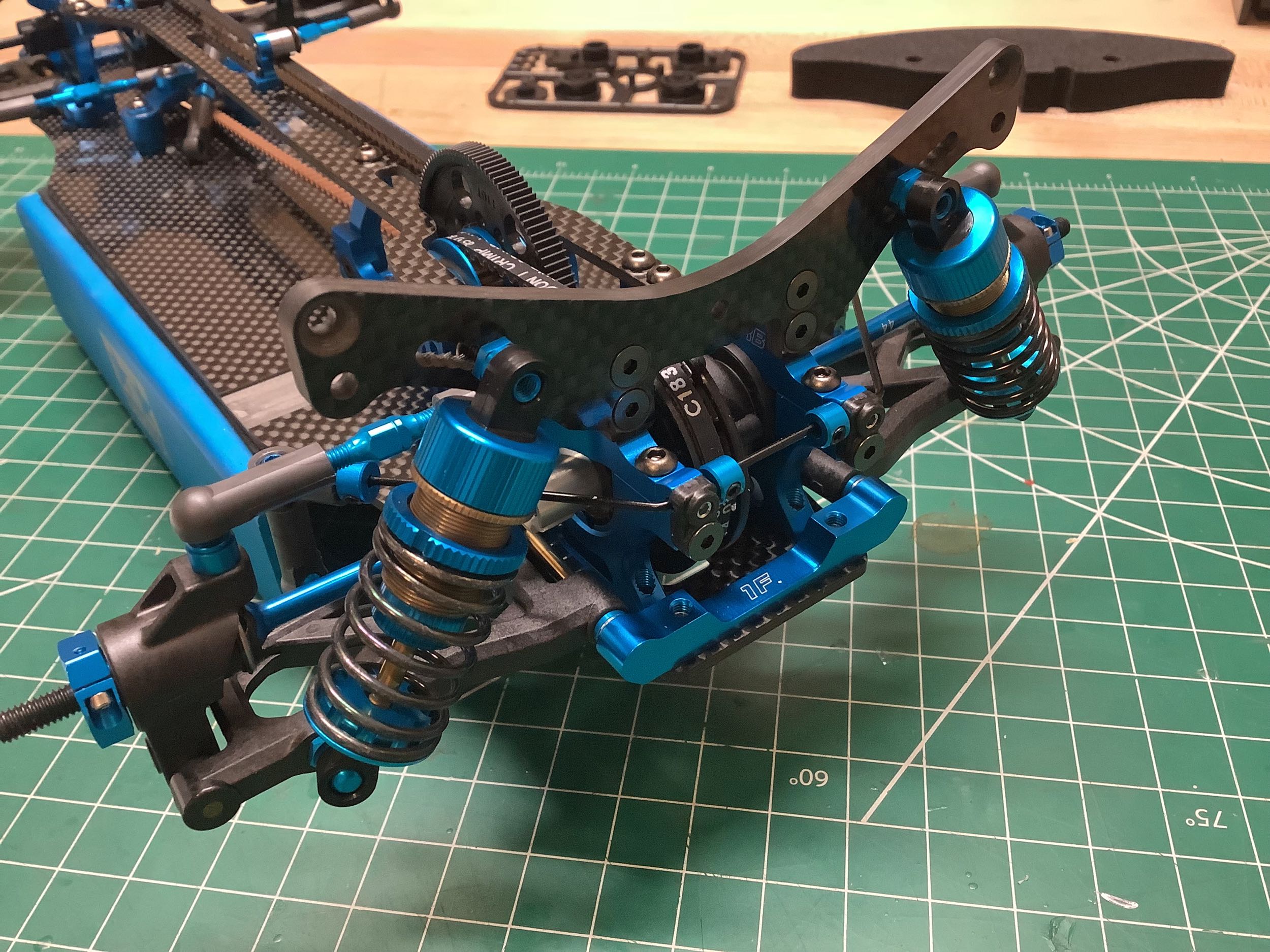
coating. The rear suspension mount is now 1F which, in combination
with the 1X forward mounts, gives a rear toe angle of 3°. The
uprights have 0° of toe.
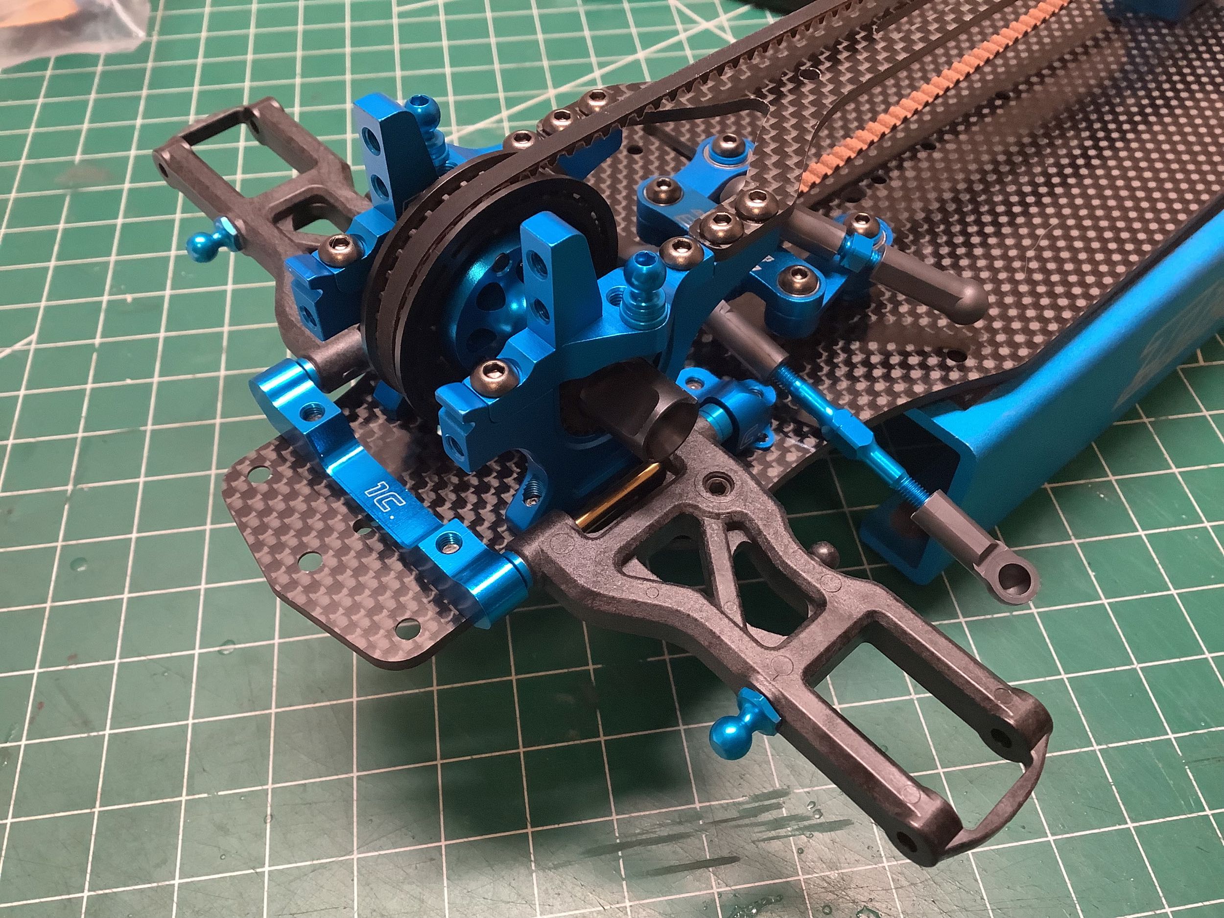
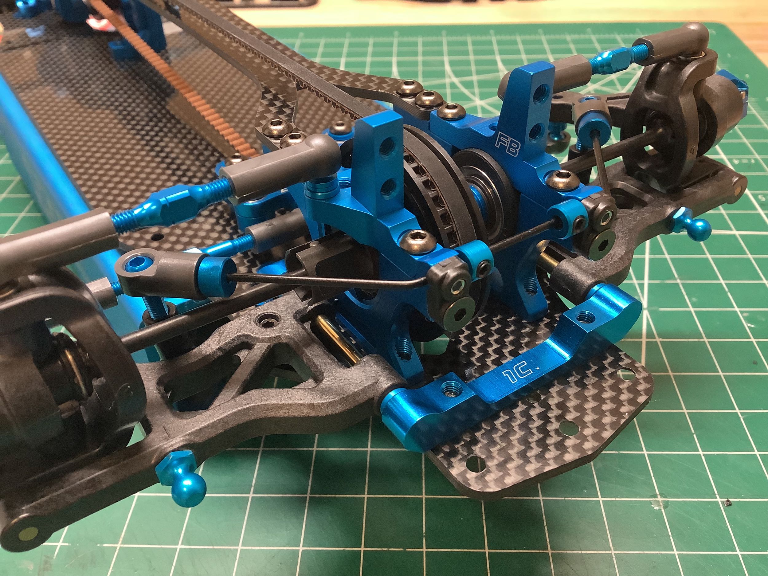
The front suspension is also a straight duplication of the TRF
418. Even the 1C forward suspension mount and 0.5mm spacer are the
same.
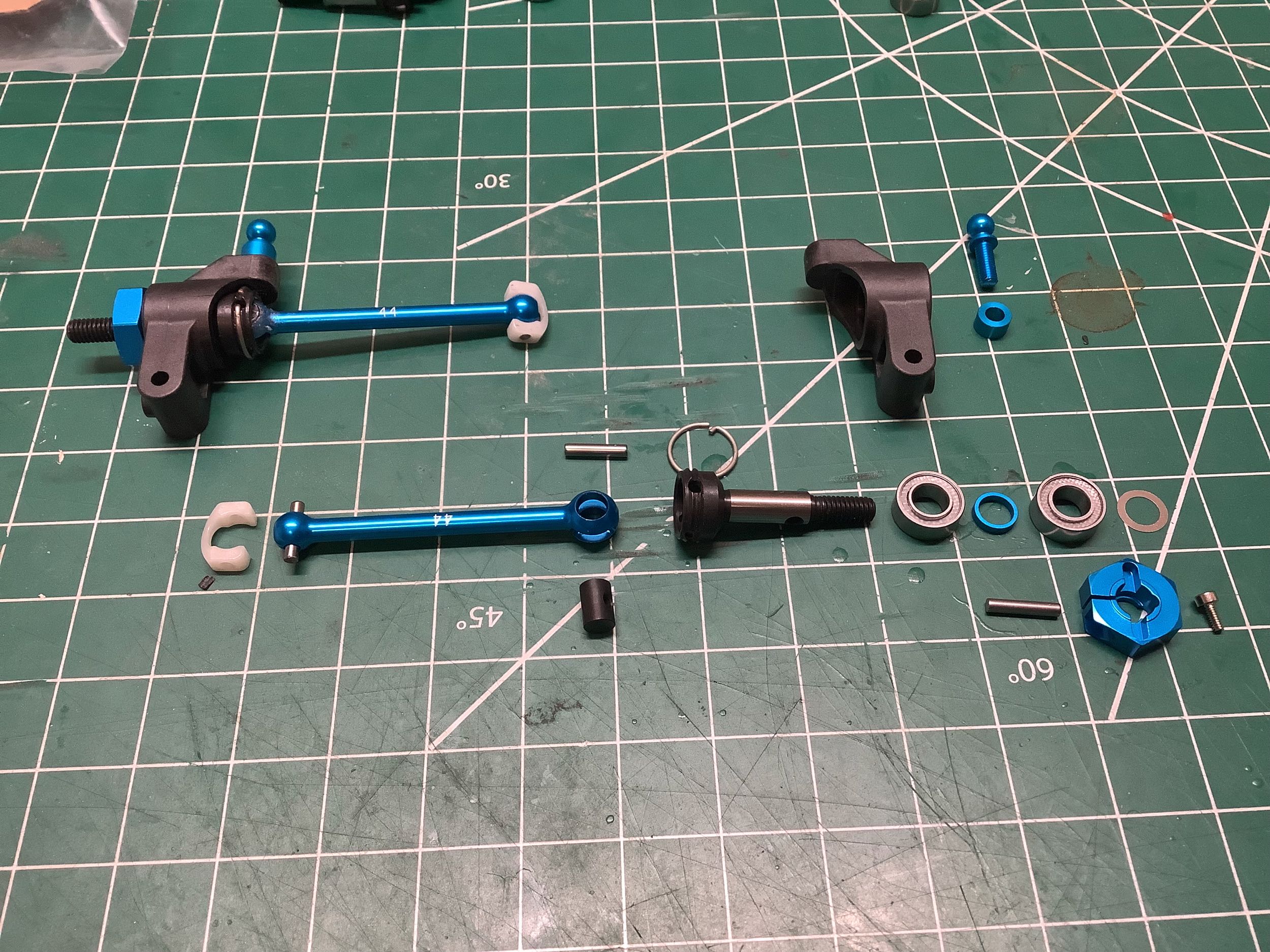
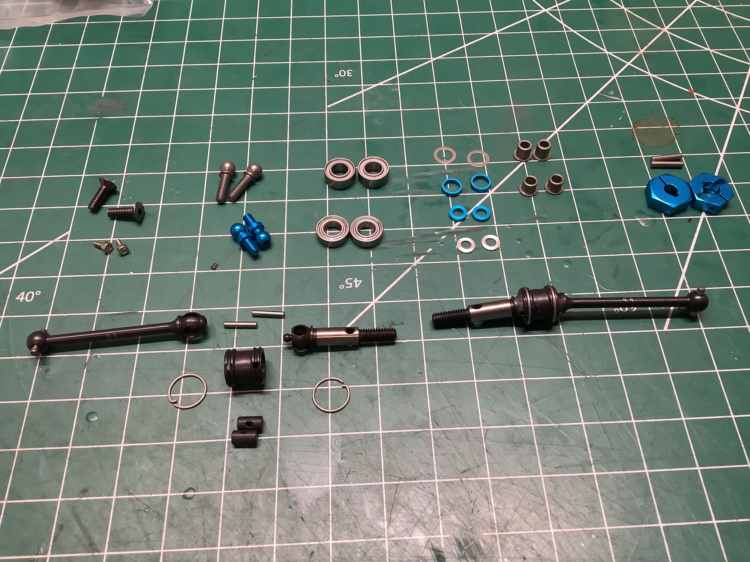
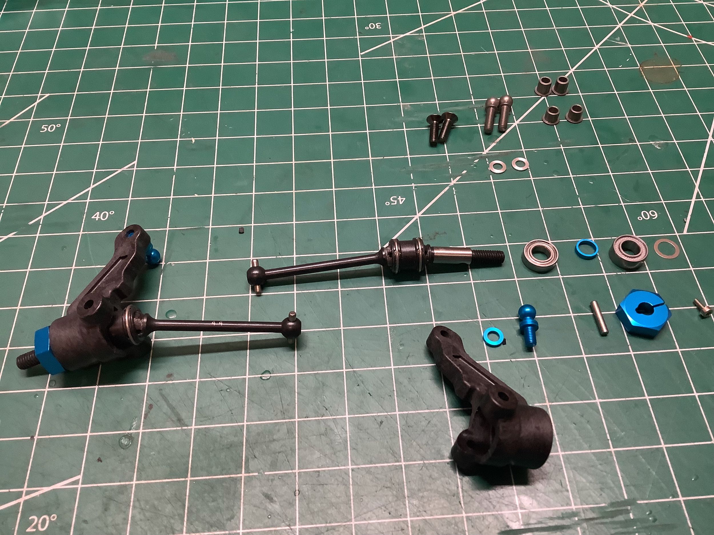
The rear uprights, aluminum CVD axles, and camber links are also reused from the TRF 418. Noticing a pattern here?
The double cardan steel axles are also completely reused from the TRF 418 except that the axle caps have been removed.
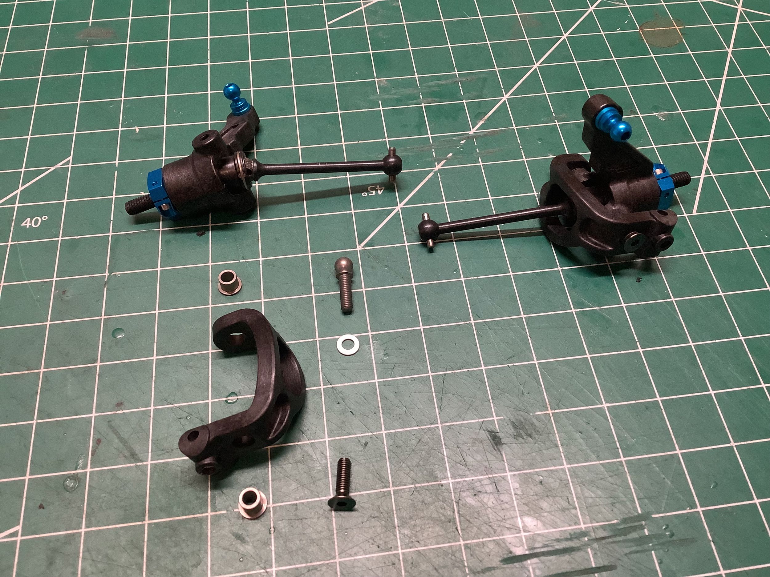
Finally something that changed! Although both the TRF 418 and TRF
419 use C-hubs with 4° of caster built-in, the new F-parts have a larger
opening to make more space for the double cardan axle.
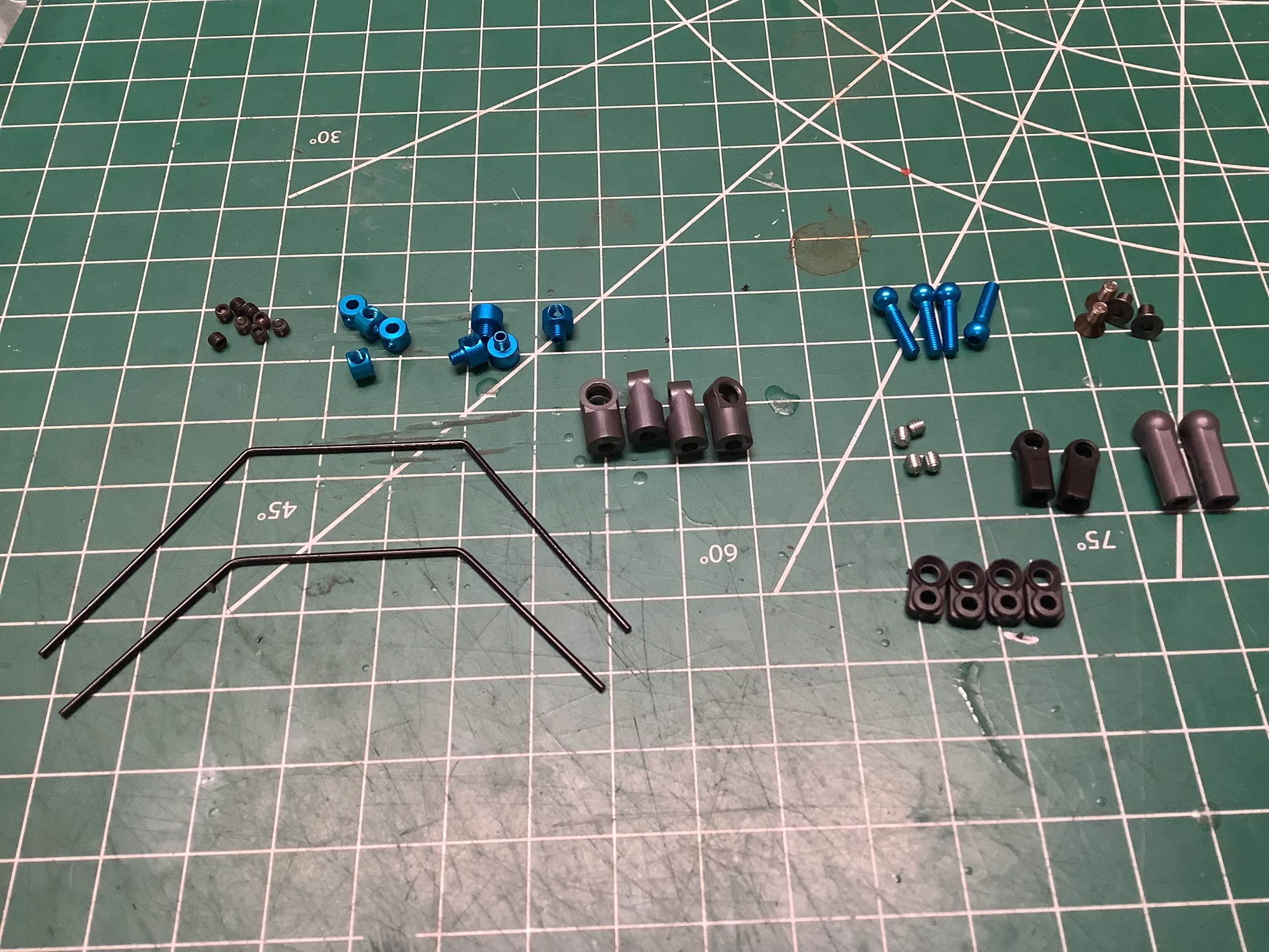
Time to build the sway bars. The TRF 419 uses the same system as
the TRF 418, but the 419X updated it slightly and then the 419XR
introduced bearing support which carried forward to future models.
Both the front and rear stabilizers are medium-soft.
Here are the completed front and rear suspension assemblies. If
you compare these to the pictures from the TRF 418 you'd be hard pressed
to see any differences other than the color of the pulleys.
The differences to the dampers were discussed previously. While
these may look very familiar, the inner diameter has increased from 10mm
to 10.5mm. This means a new cylinder and piston, but
interestingly the threaded caps and spring retainers stayed the same
which implies the outer diameter didn't change and therefore the wall
thickness must have gotten thinner. This constant outer diameter
makes these dampers compatible with any other chassis that used the old
dampers, whereas the even bigger 11.2mm dampers introduced with the TRF
419X required other changes to incorporate them. The spring rate
has also softened for the TRF 419. The carbon shock towers are
shown on the right. The TRF 419X changed them completely to
accommodate the shorter dampers.
Now the front and rear suspension are complete with the dampers
installed. I never get tired of looking at (or building) a TRF
suspension.
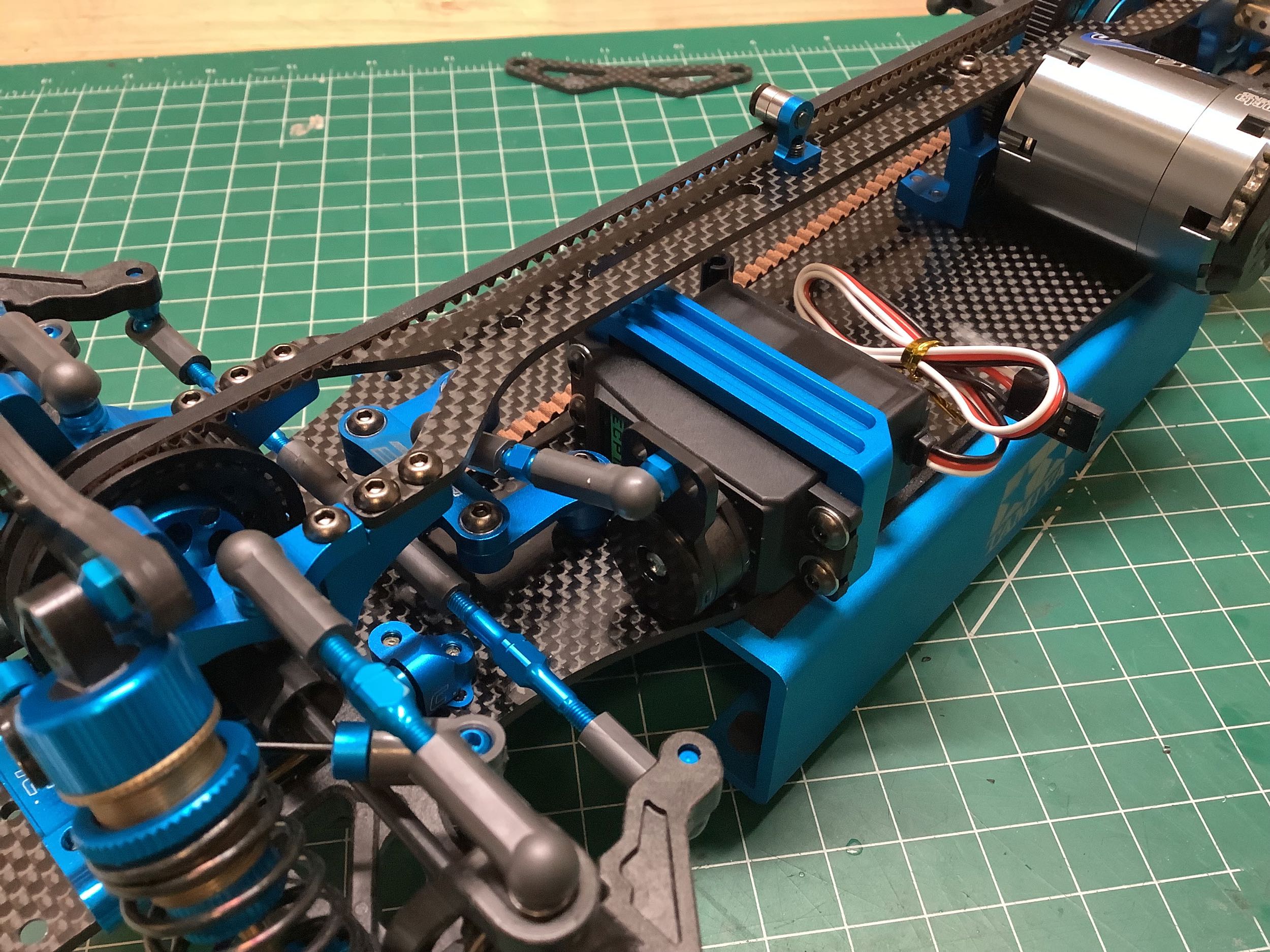
I didn't have a display motor yet when I built this model so I used a
TRF Transpeed motor I had available. This is destined for a TRF
201 which will actually be driven, so I'll be swapping it out
later. On the right you can see the new motor mounting method
which uses two screw holes on the bottom of the motor located 60° apart
and therefor precludes the use of traditional brushed motors (even for
display).
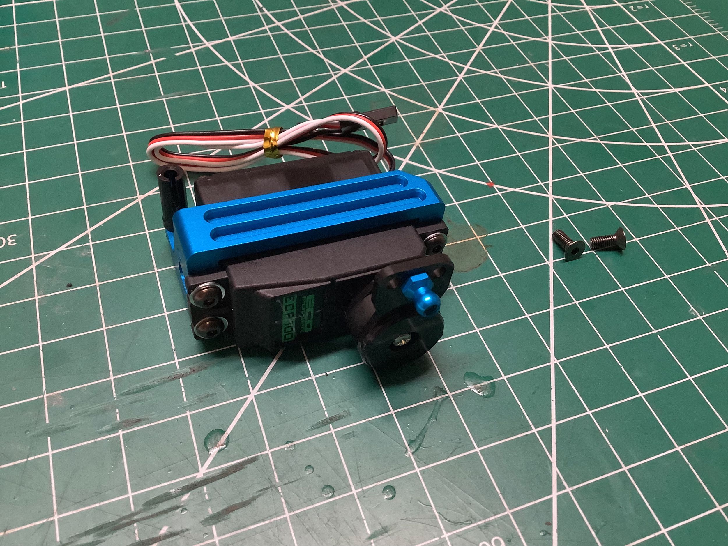
The cantilevered servo mount is also reused from the TRF 418. Both
use a high torque servo saver which sadly does not include an aluminum
horn.
These pathetic plastic battery holders are reused from the TRF 418 but
oriented slightly differently. In both cases, there is no actual
retention and glass tape must be used. The TRF 419X improved this
slightly with easier adjustability and the 419XR improved them
significantly with lateral support, but both still required glass
tape. The front bumper and mount shown on the right are also
unchanged.
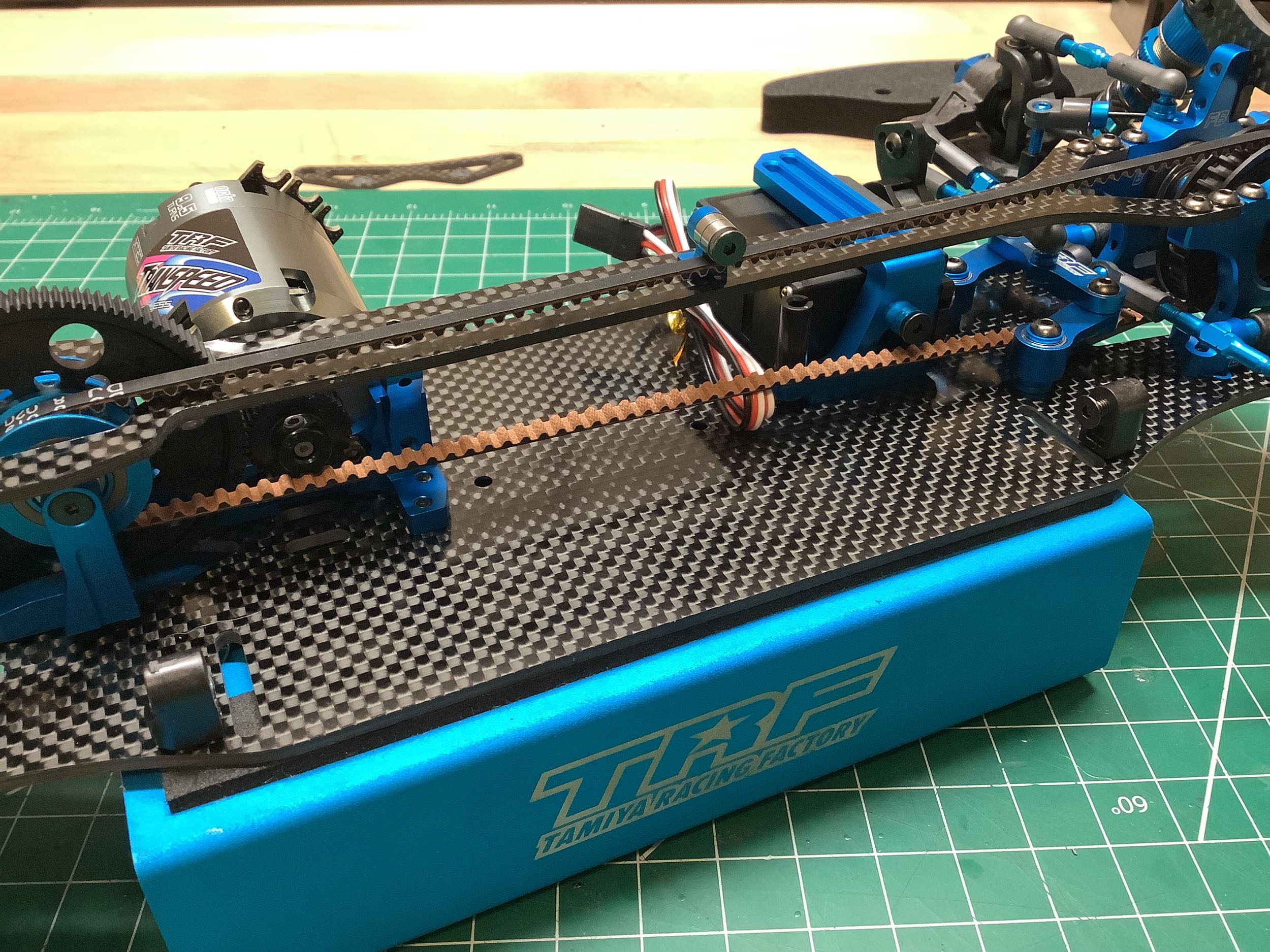
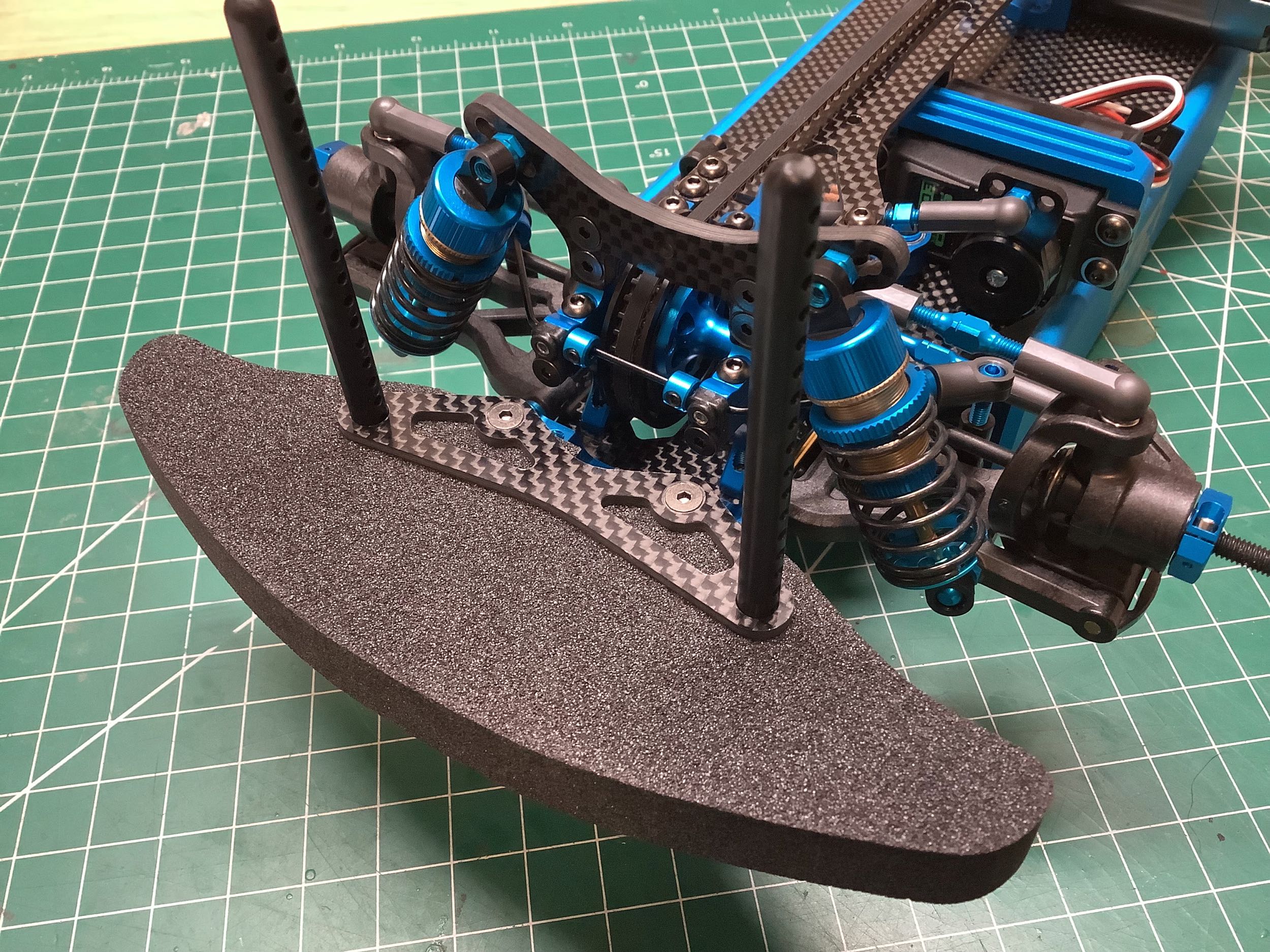
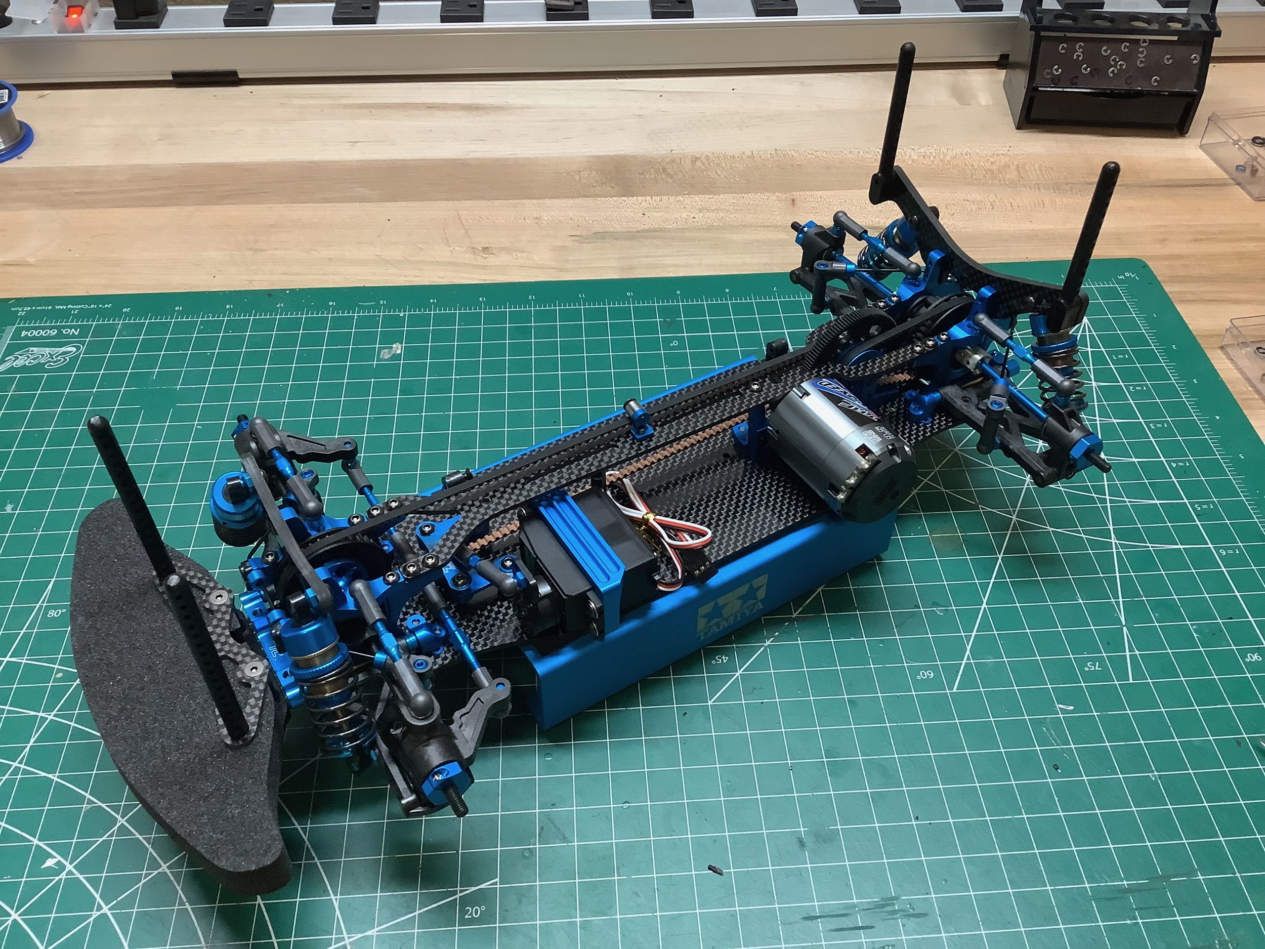
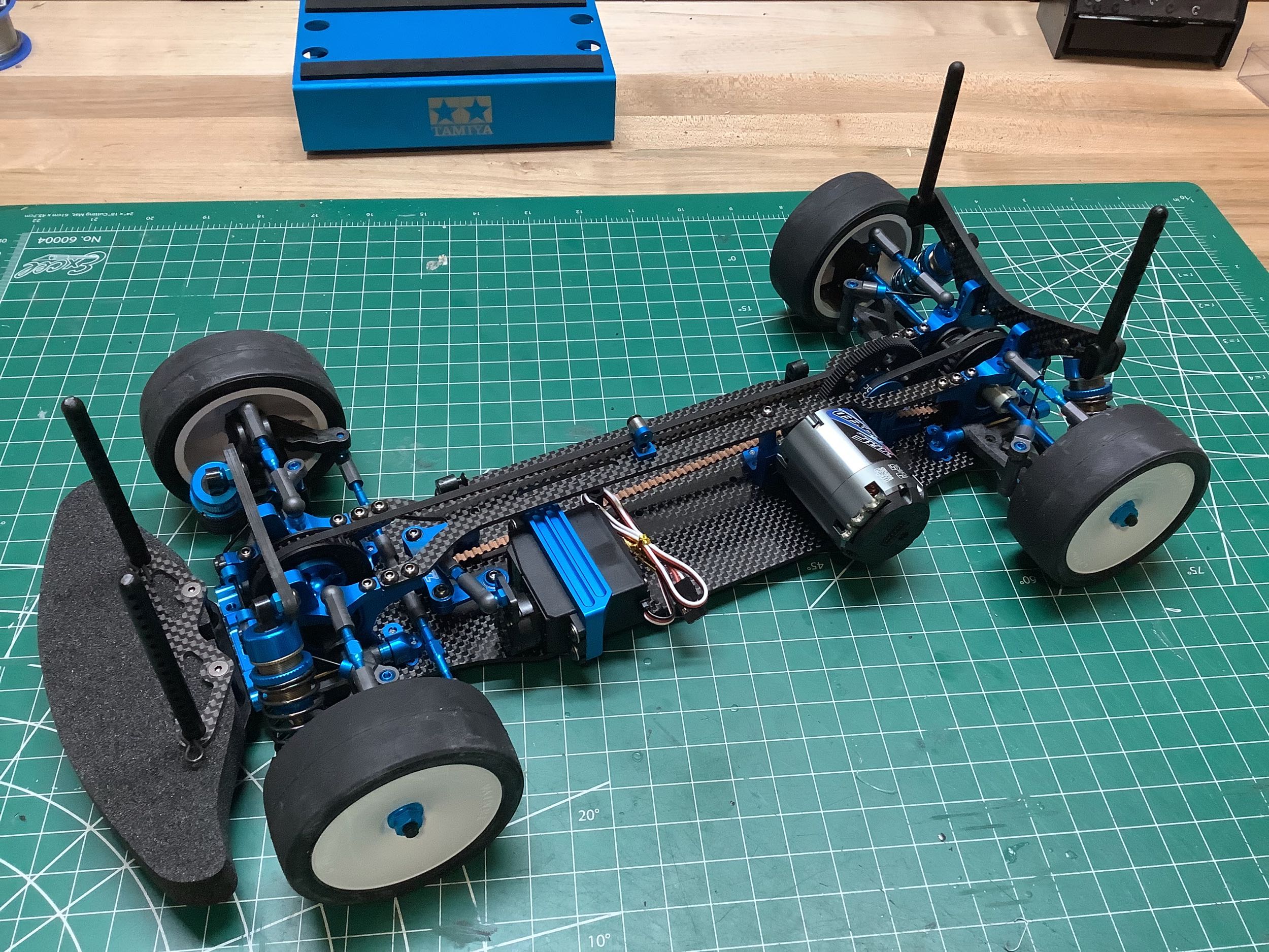
The addition of the body posts completes the chassis. Like all
recent TRF chassis, no wheels or tires are included so I've added
standard dish wheels and slick tires.
©2025 Eric Albrecht