Traxxas Bronco Project
Page 1: Re-Assembly
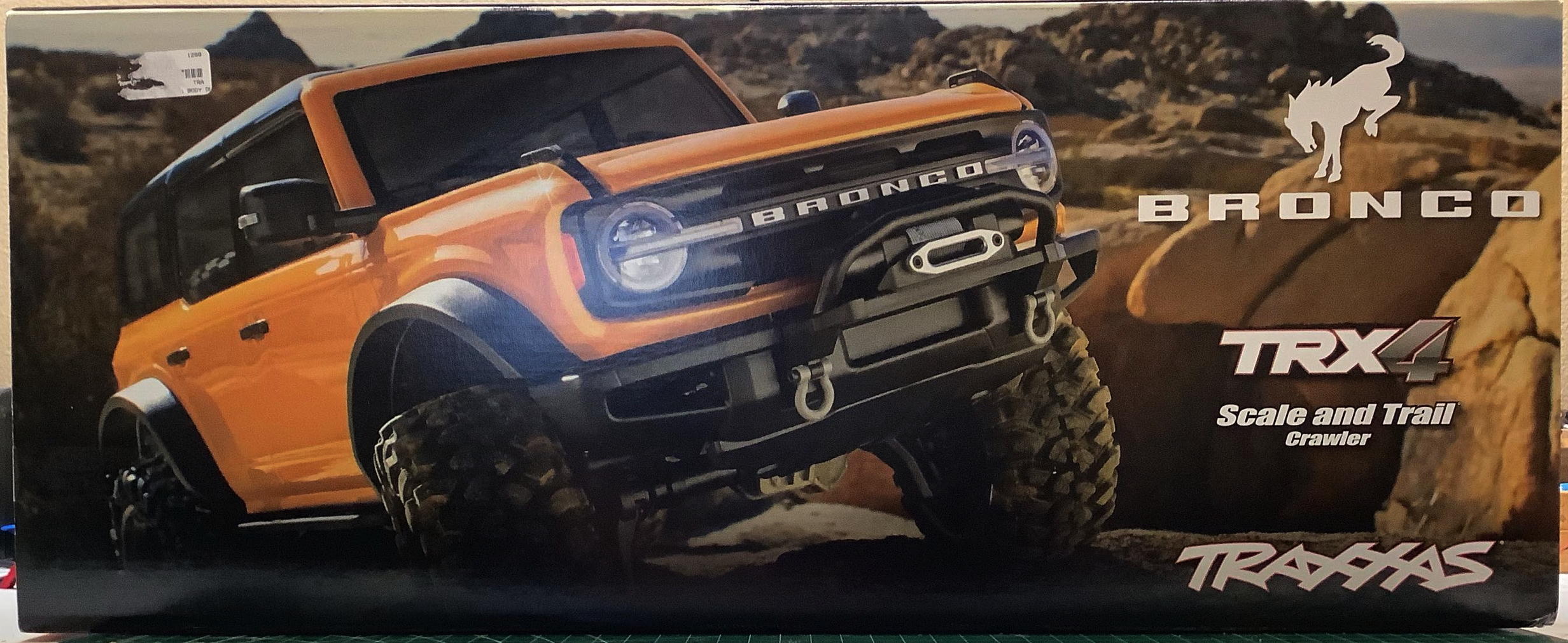
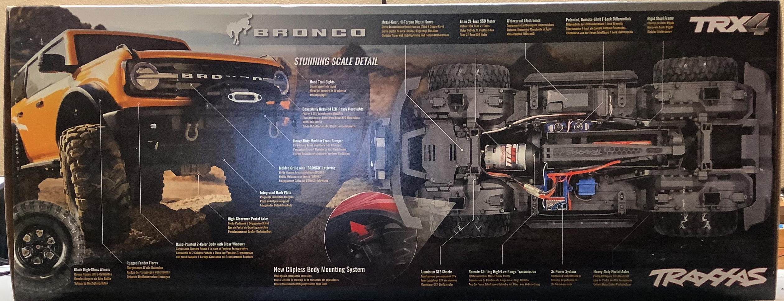
The Bronco comes in a surprisingly small box packed very tightly with
goodness. Traxxas does a good job of highlighting all of the main
features.
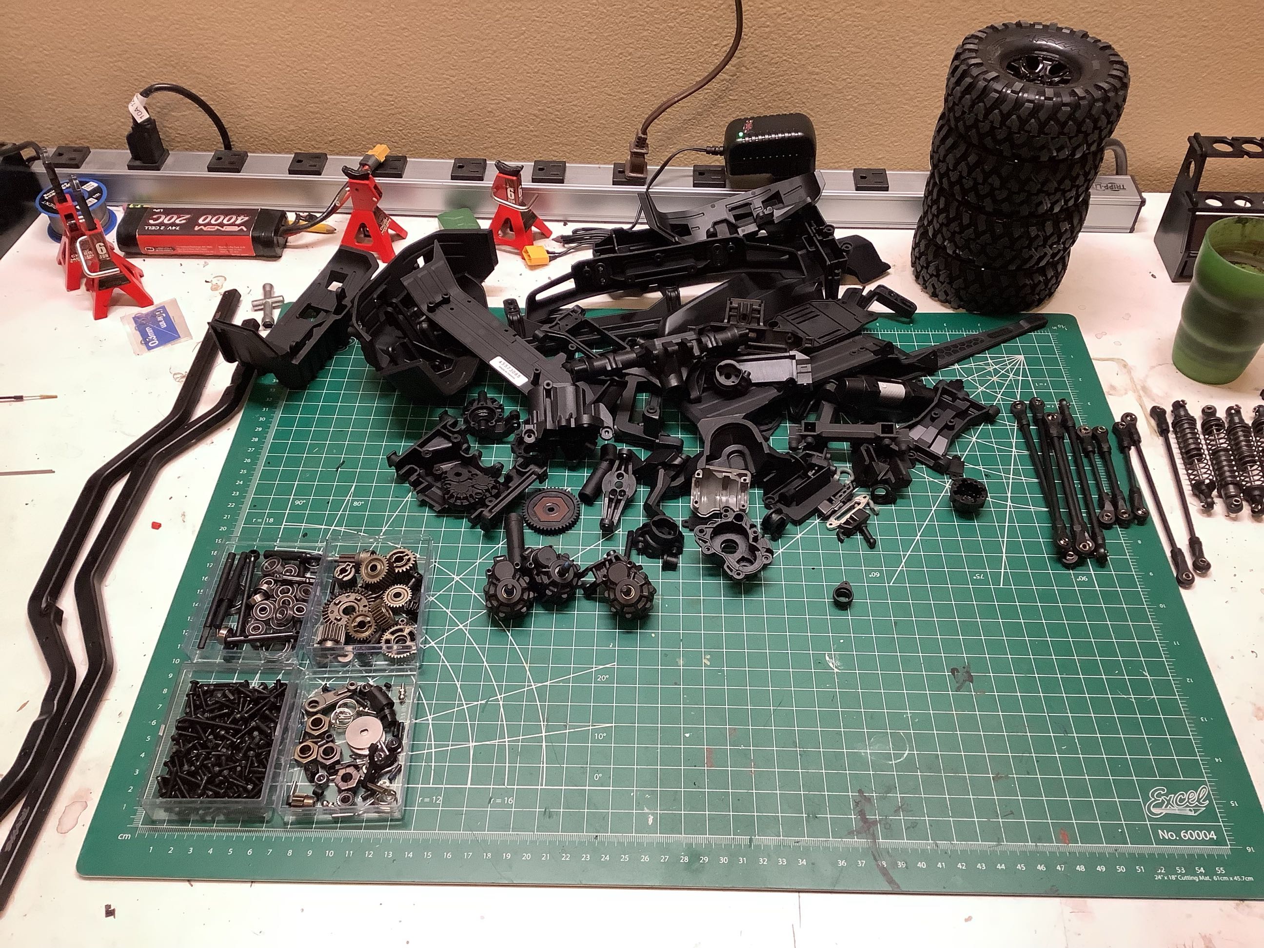
I didn't even try the model out first, I went straight to tearing it all
down and rebuilding from scratch. I'll admit that I only tore
down the front portal box since the rear is the same so rebuilding one
will give me the experience I am looking for. I also didn't
disassemble the shocks or links. You can see what I ended up with
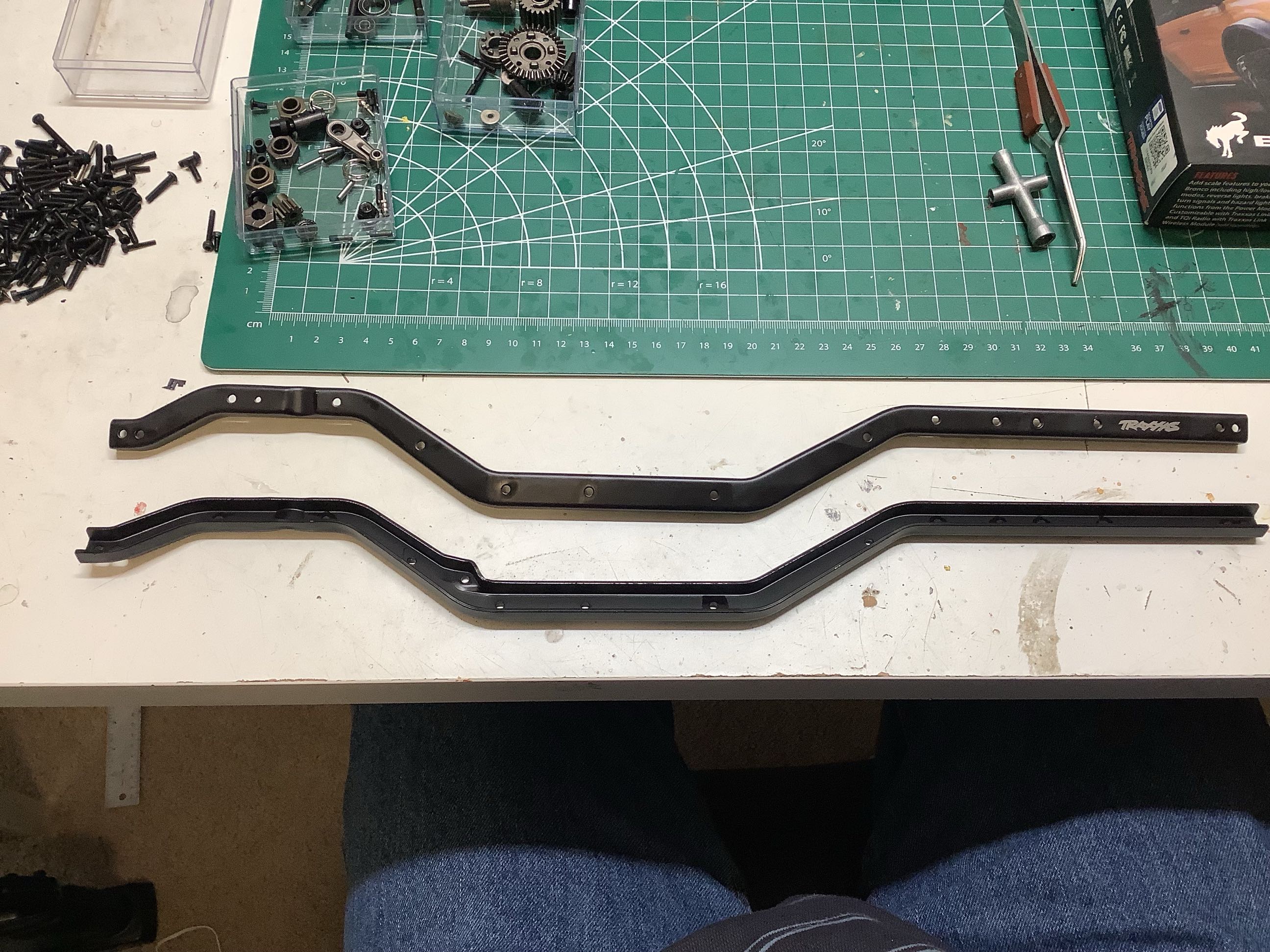
after the teardown on the left. On the right you can see the
formed C-channel chassis rails.
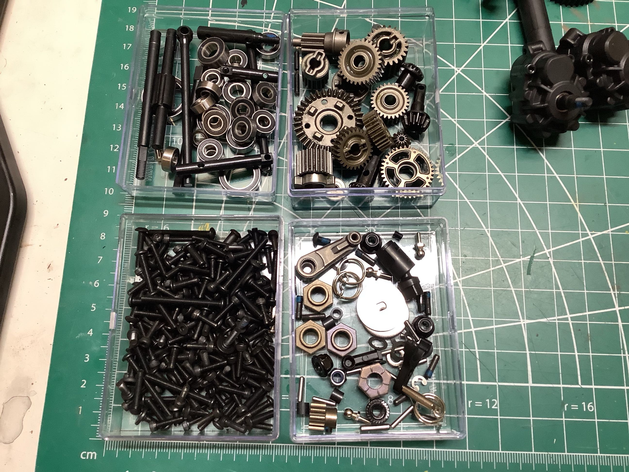
Here is the hardware somewhat sorted. Hex fasteners are lower
left, bearings and shafts are upper left, gears are upper right, and
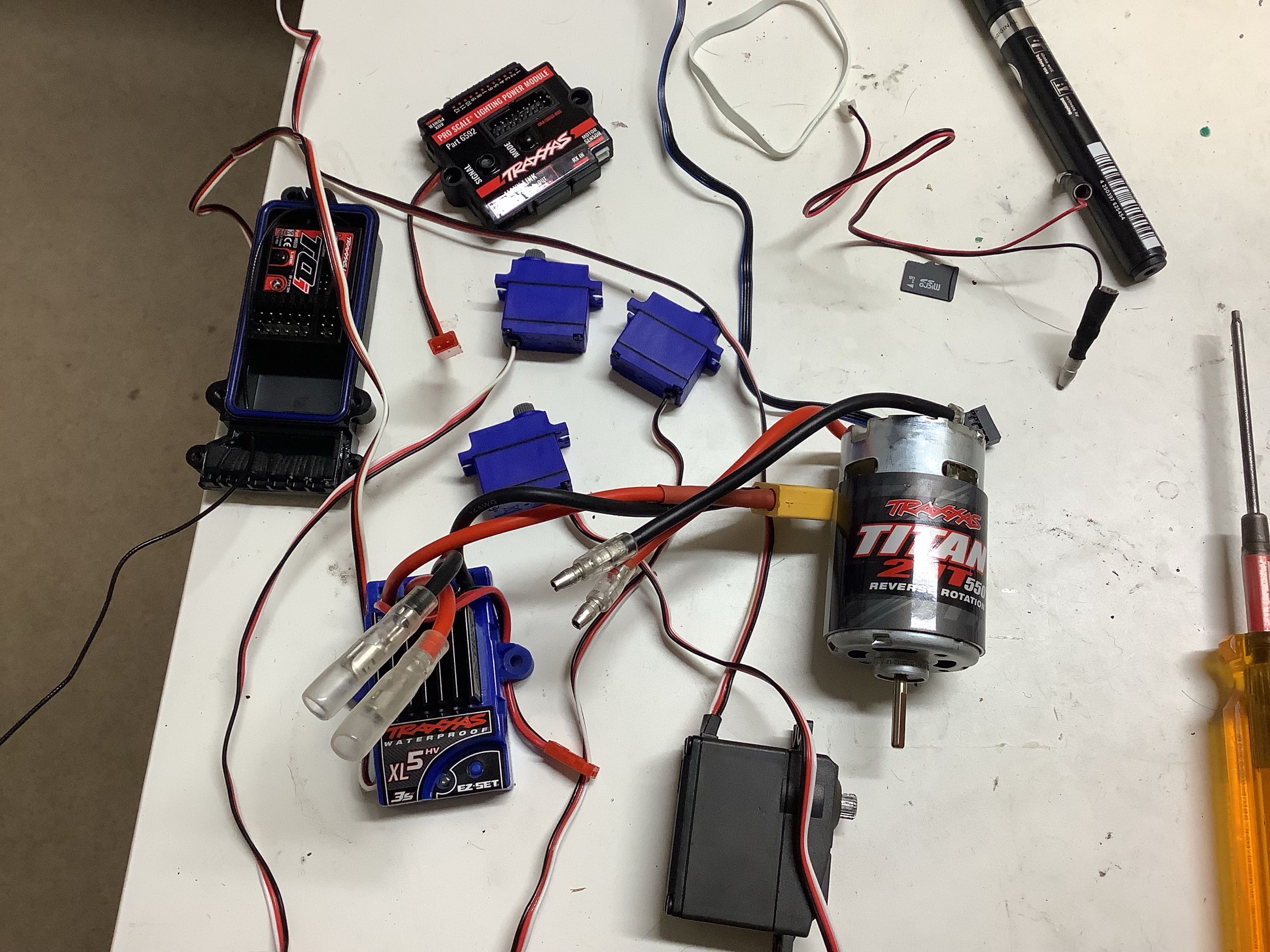
miscellaneous hardware is lower right. On the right you can see
the complete electronics package. The controller for the lighting
package I added is also in this picture. The 3 micro servos
control the transmission and differentials. This might be a cheap
brushed motor, but it does a very good job and I didn't see any reason
to replace it.
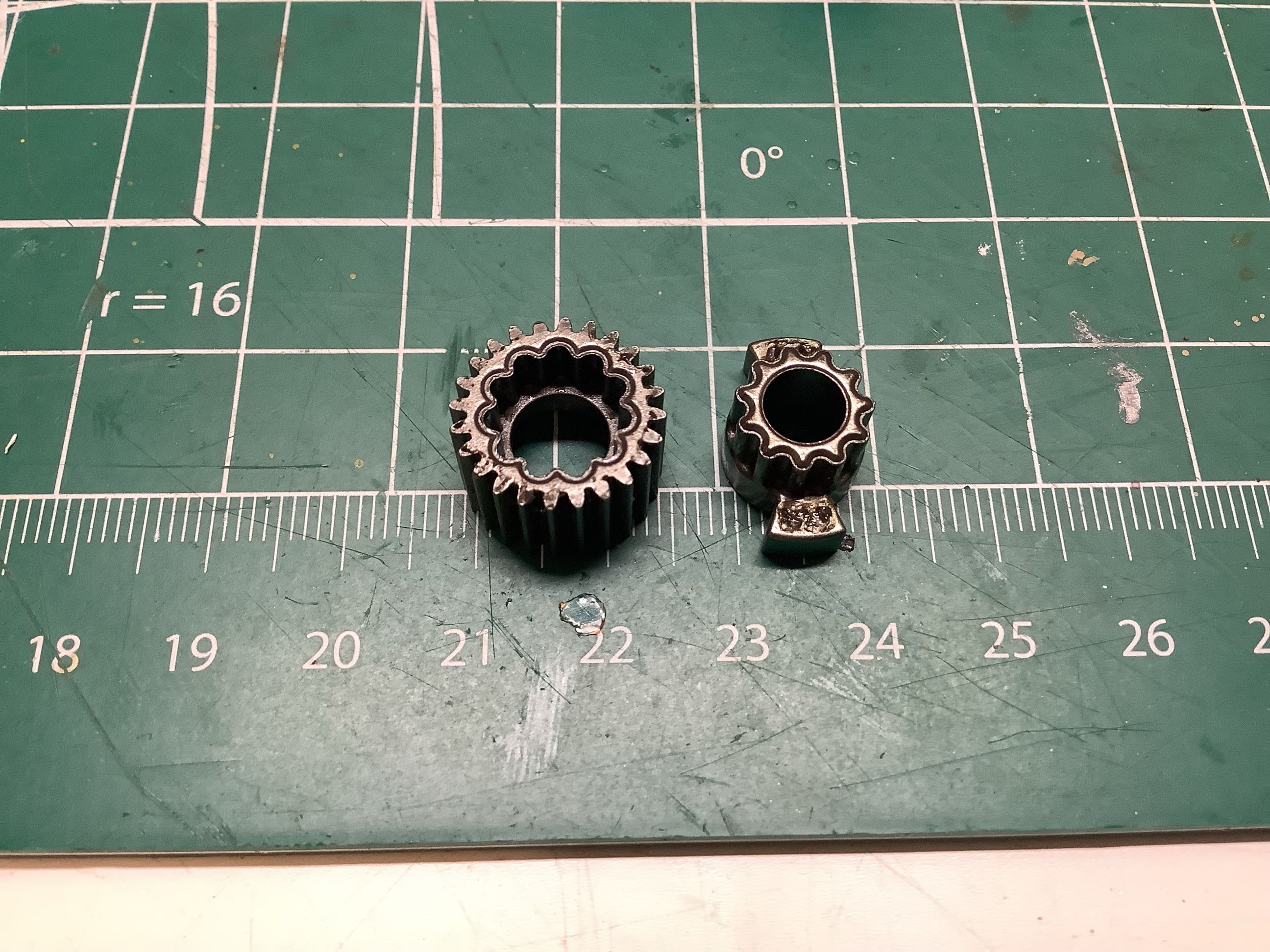
Let's get started on the transmission. The two gears shown on the
left nest together using an interesting "flower petal" shaped
spline. The result in shown on the left hand edge of the right
picture. Those two hourglass shaped driving dogs will mate with
those on the black drive ring at far right. The cruciform slot in
the same part fits over the input shaft. There are a matching set
of driving dogs on the opposite side of the black part which fit into
the slots on the middle gear. Depending on whether the driving
ring is pushed to the front or back, one or the other of the gears is
locked to the input shaft. Note that both gears ride on bearings
which allow them to spin freely on the shaft when not engaged.
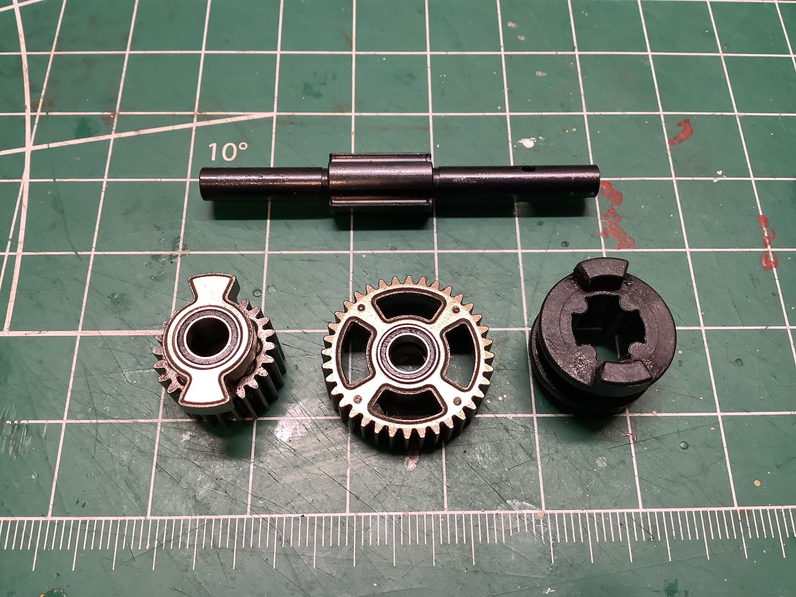
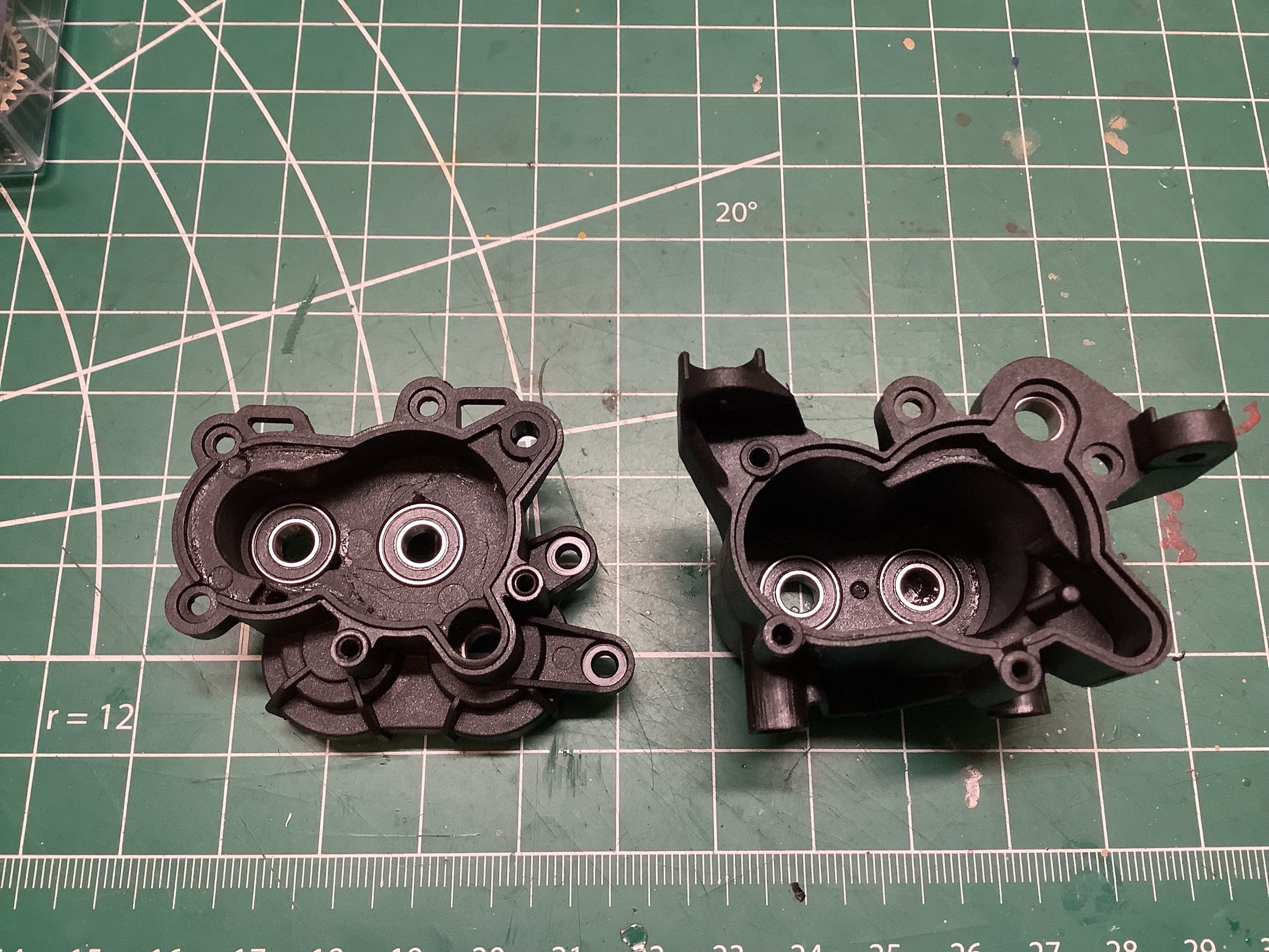
Here are the plastic main parts of the gearbox housing with bearings
inserted. On the right the main gear shafts have been
inserted. That little silver tab sticking out of the gearbox will
be used to drive the shift fork adjusting the gearbox from High to
Low. I should have had a photo showing the inside of the gearbox,
but somehow I forgot to take that one.
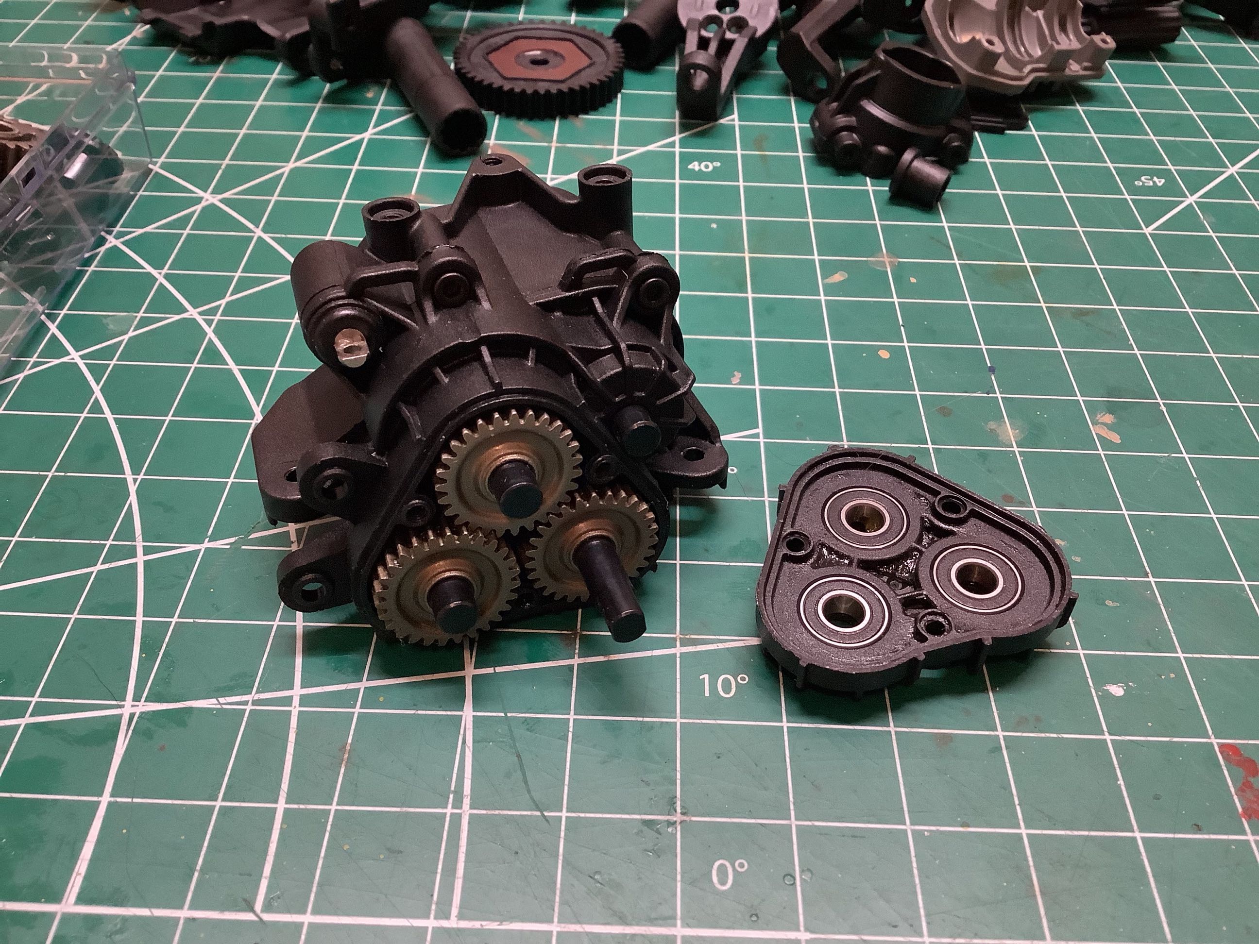
This back end of the gearbox contains the transfer case. The upper
gear is the transmission output, the lower left goes the rear drive
shaft, and the lower right goes to the front drive shaft. Note
that this means the front and rear drive shafts rotate in opposite
directions. The slipper clutch exploded view is shown on the
right. It installed onto the transmission input shaft.
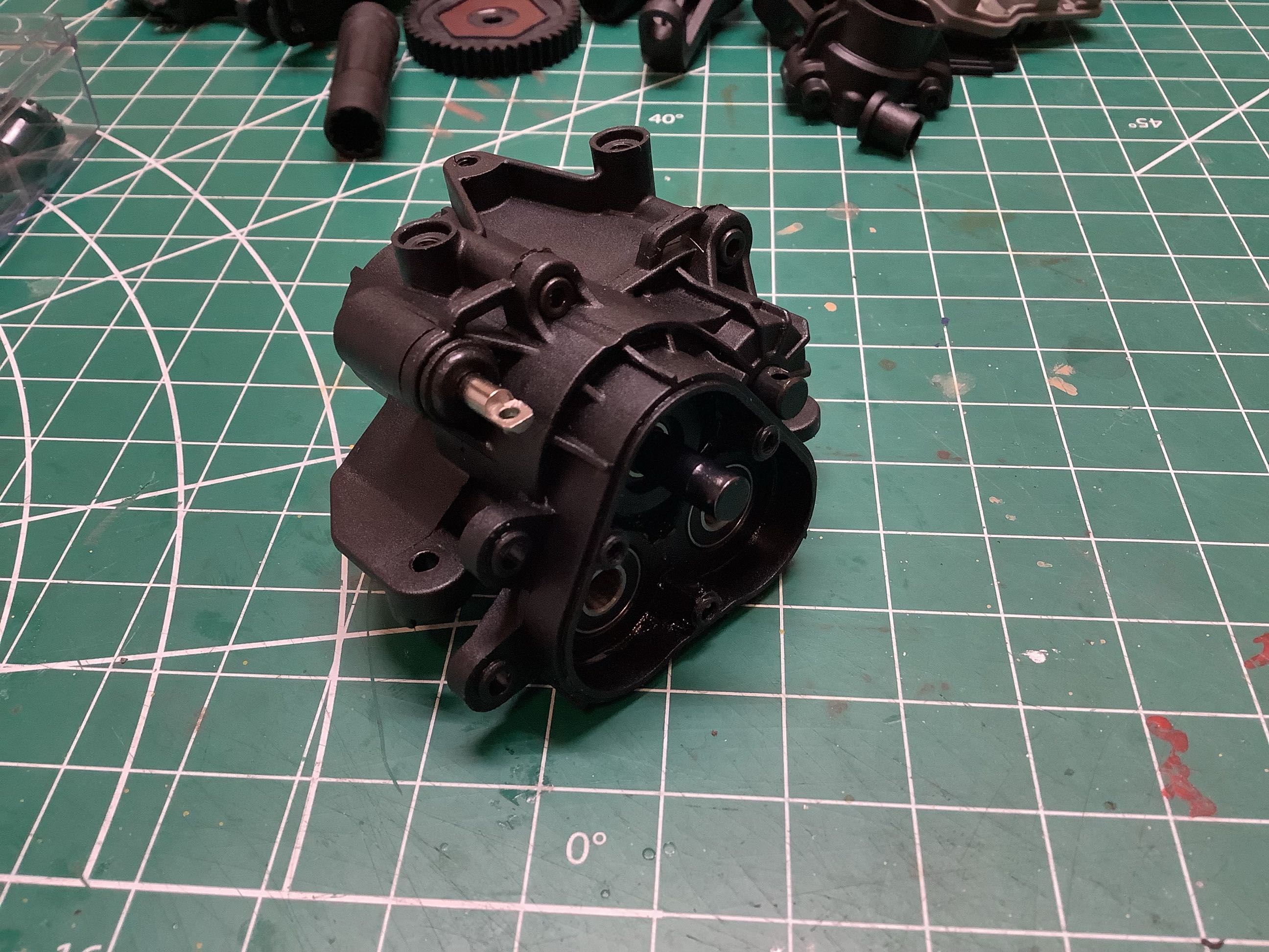
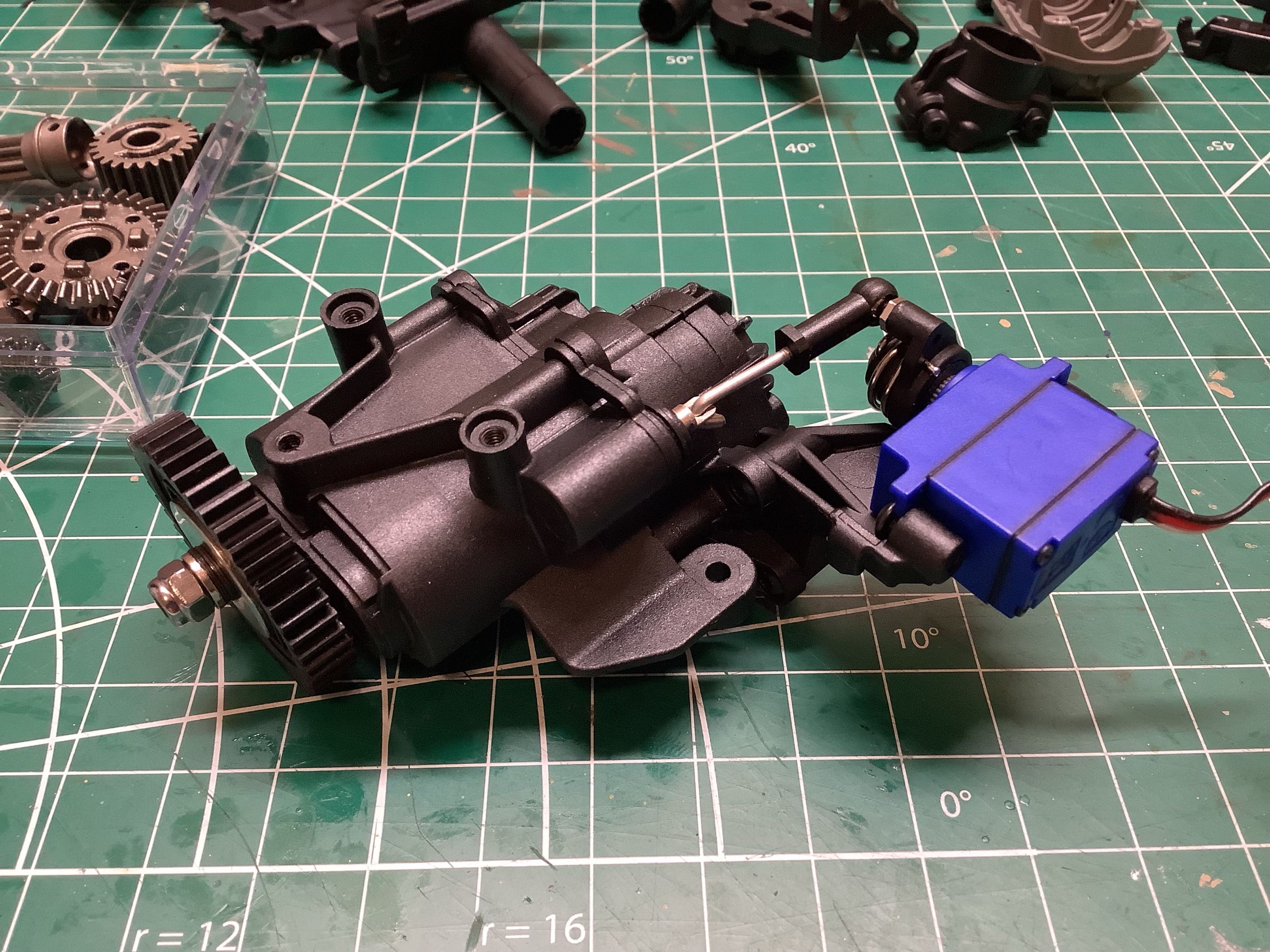
The installation of the slipper and the shifting servo completes the
assembly of the gearbox. This is a pretty compact unit considering
how much is going on inside.
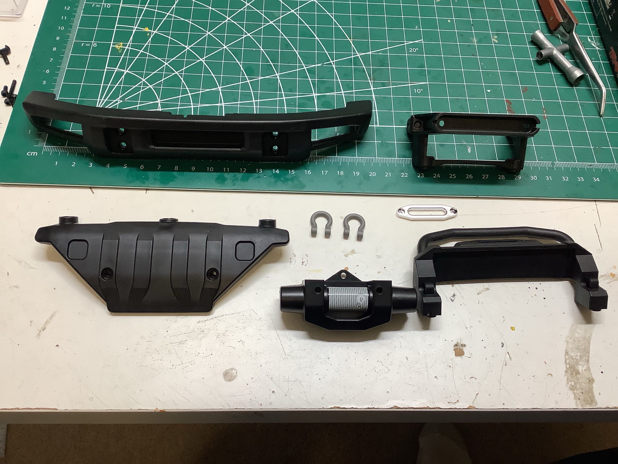
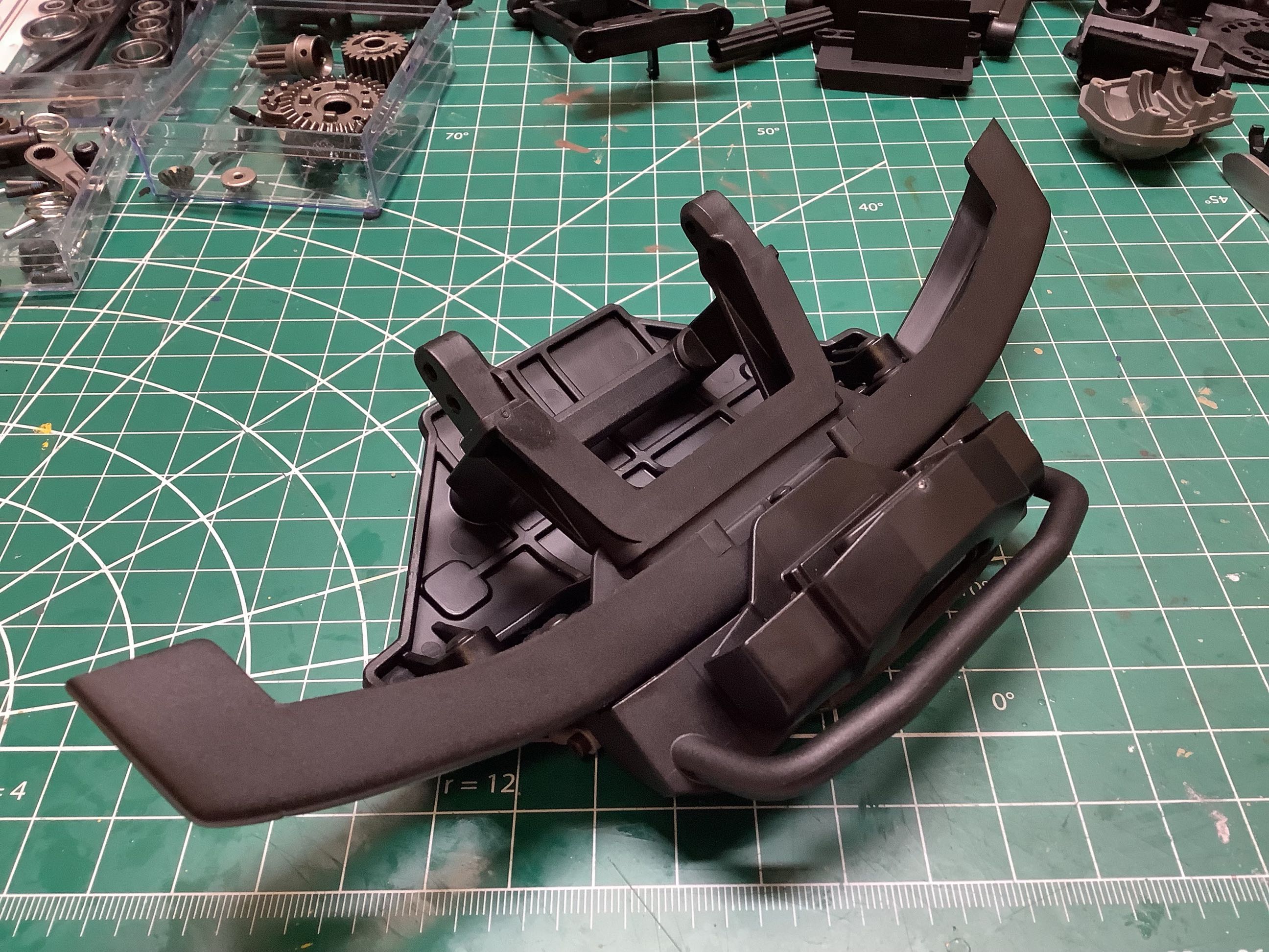
The front bumper is made up of a surprisingly large number of pieces as
shown on the left. On the right they are all assembled. The
front skid plate and chassis cross member are integrated into the
assembly as is the faux winch and D-rings.
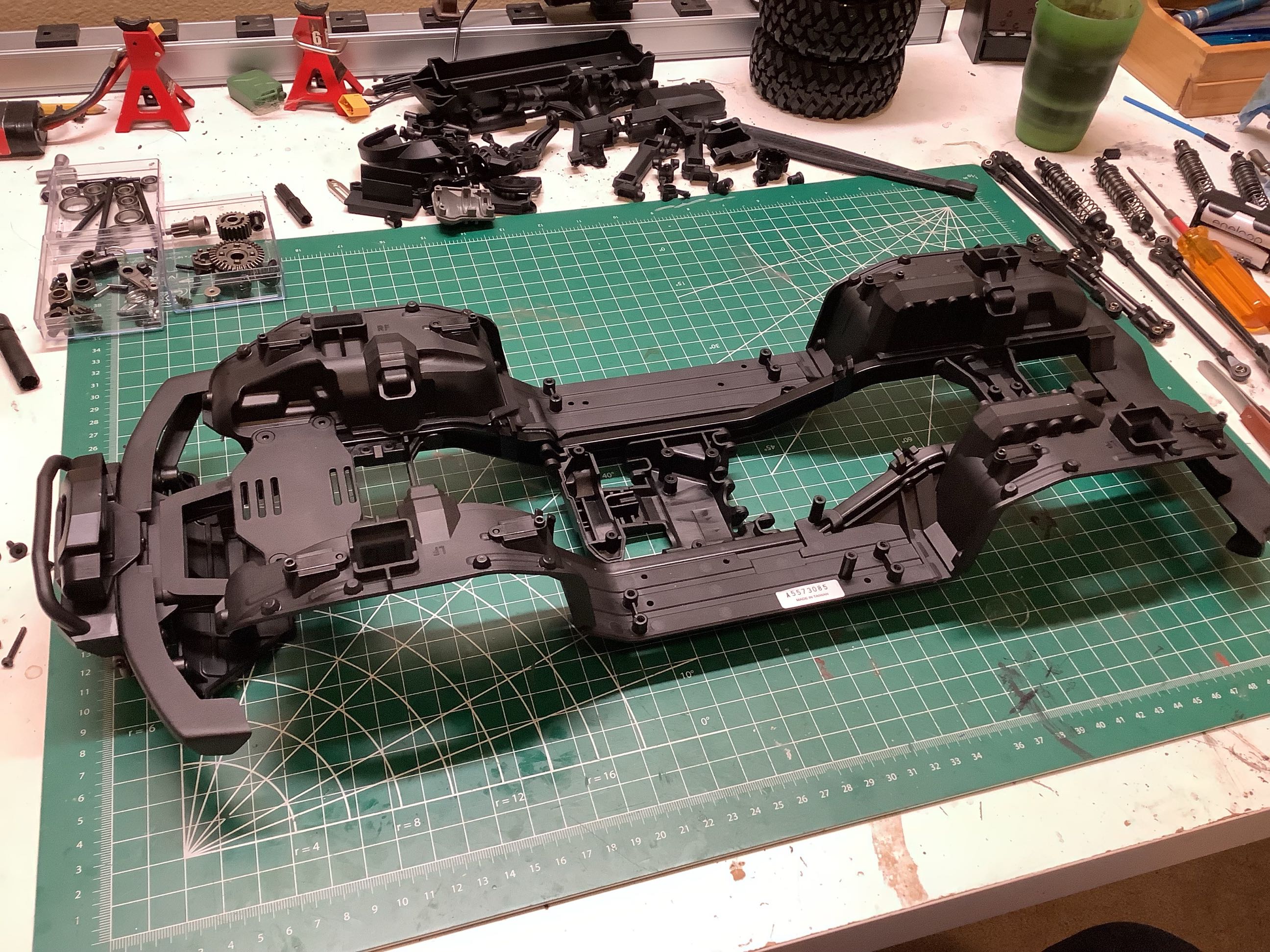
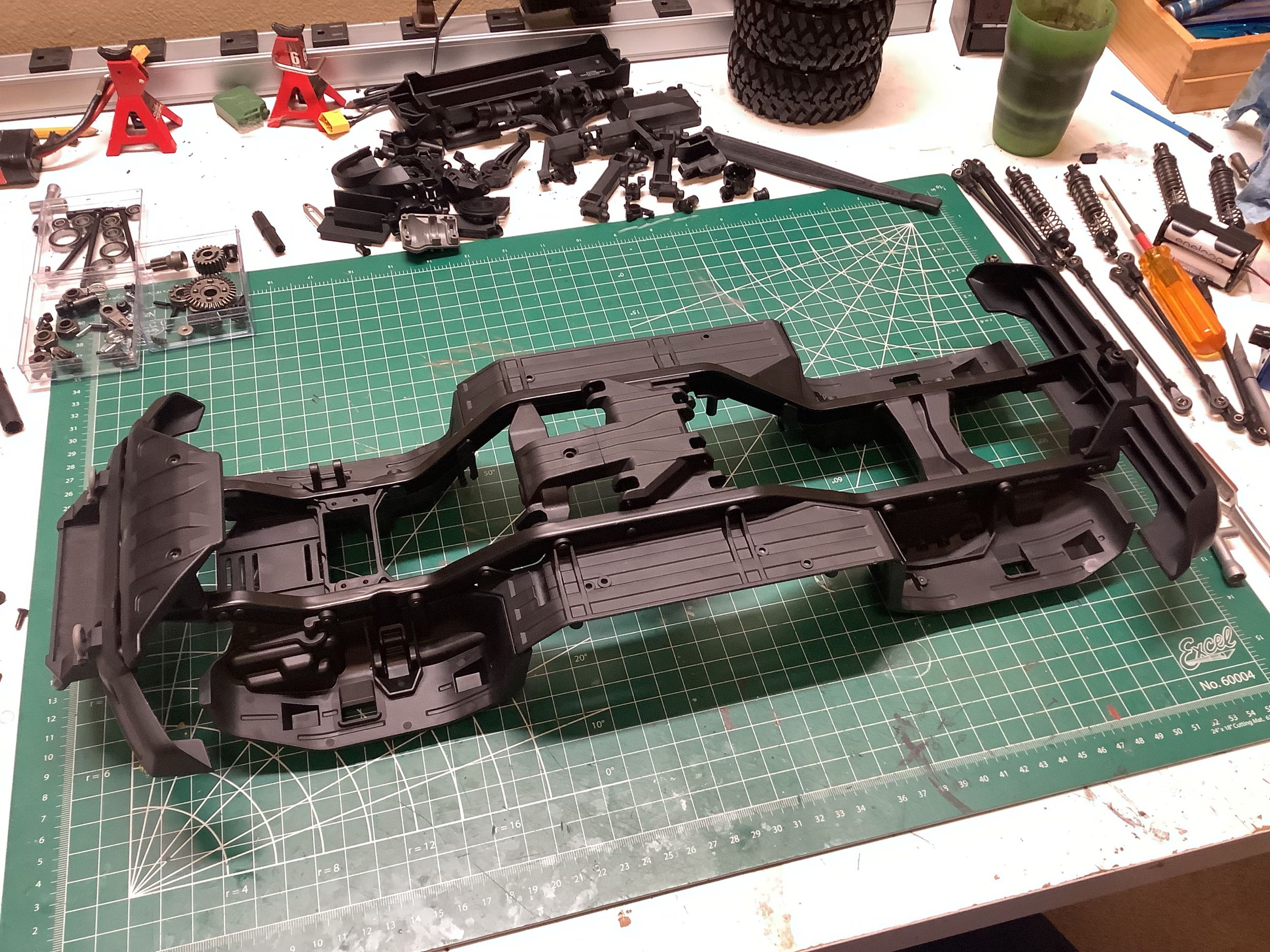
The frame goes together very quickly. The rails are metal, but all
the cross members are plastic. The shock hoops are integrated
into the inner fenders which also contain the clipless body mounting
system. Both the front and rear bumpers are connected directly to
the frame for maximum durability.
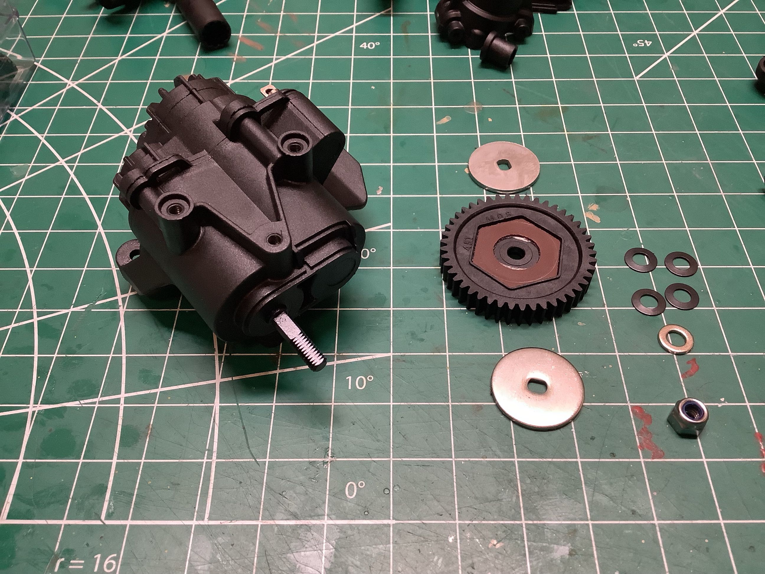
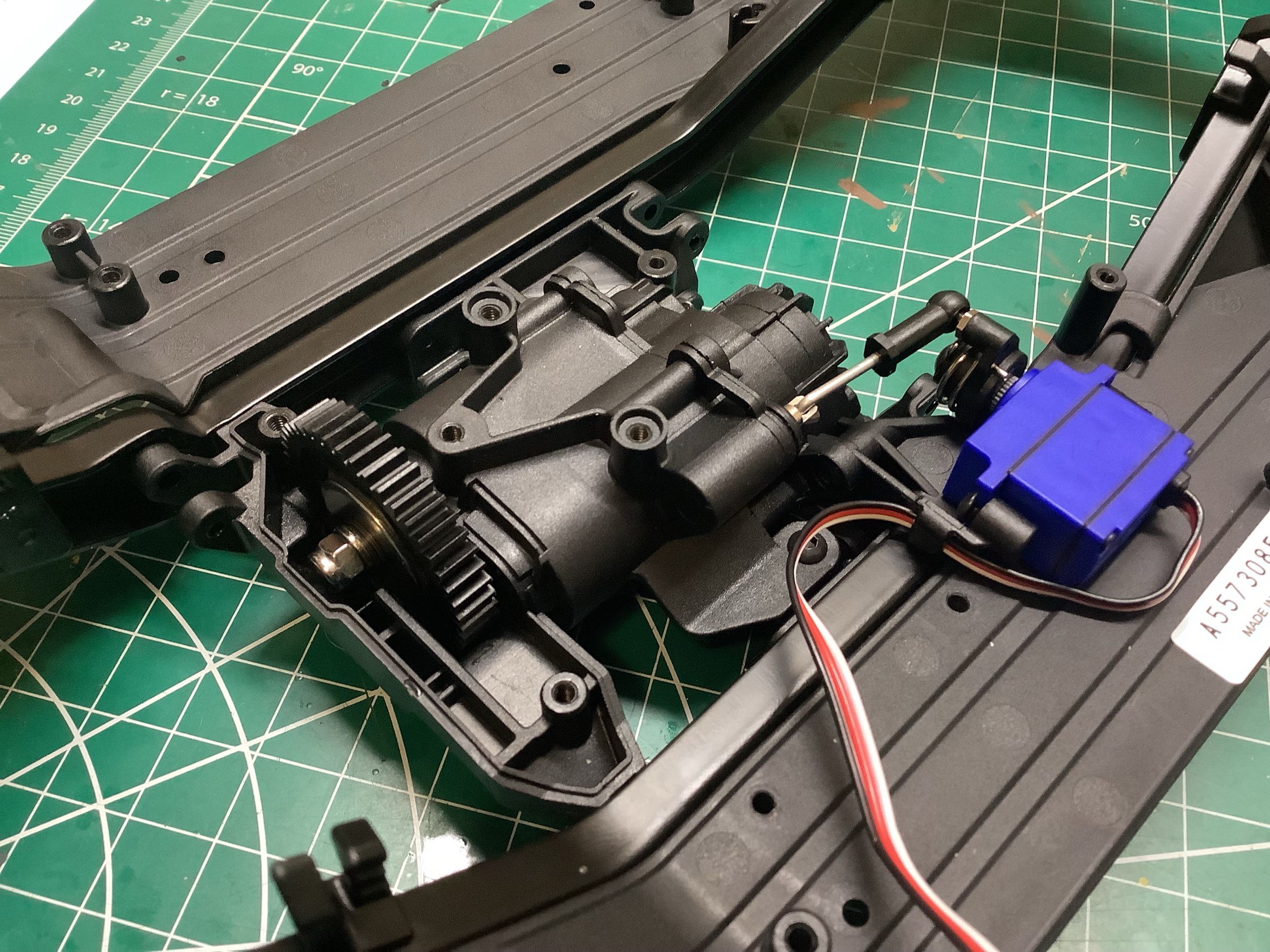
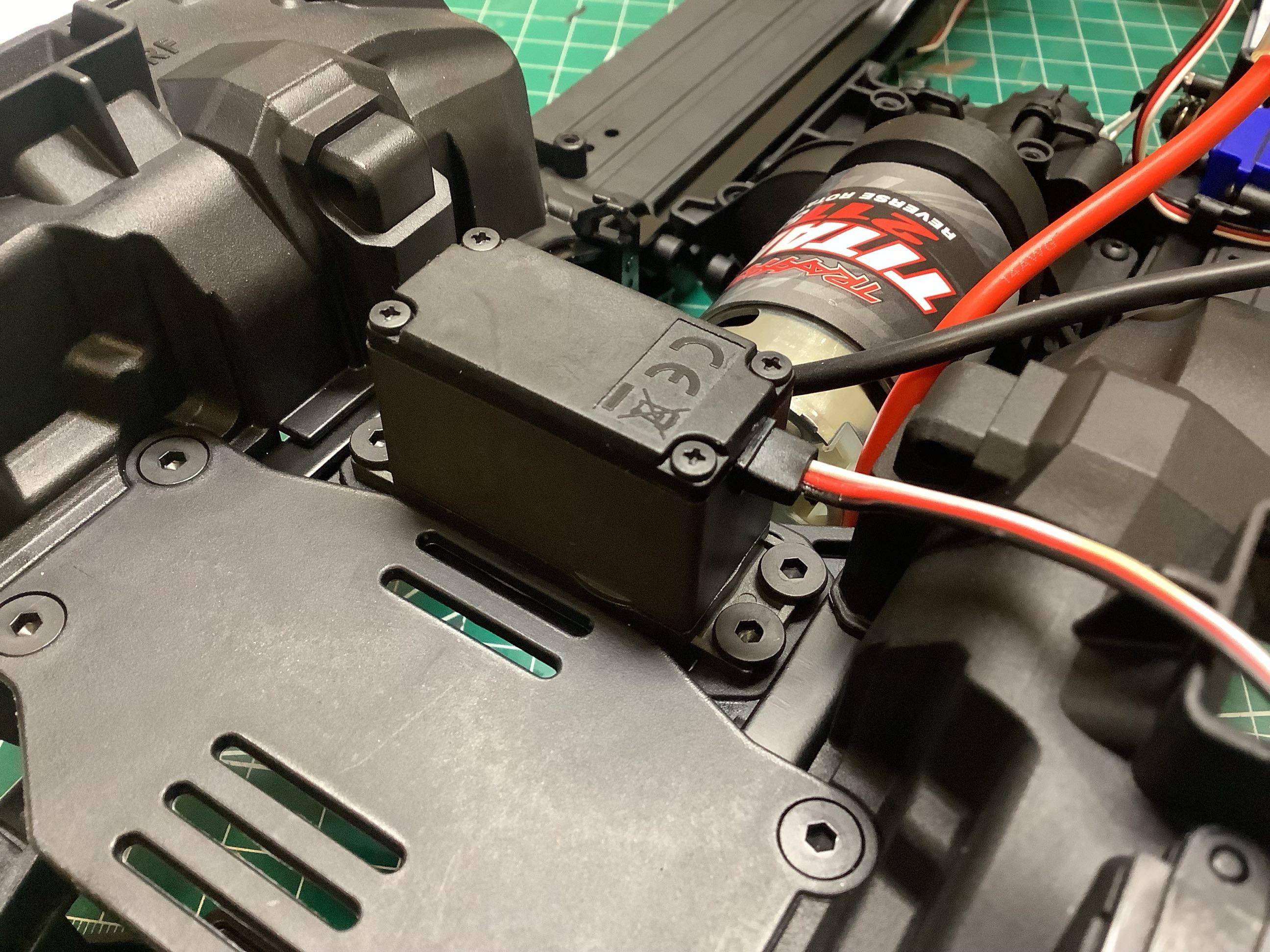
The gearbox sits directly on the center skid plate as shown. The
spur gear sits in a slot which protects the gear teeth from ingesting
debris from below. Since the servo is connected to the gearbox
housing and not the frame, chassis twist will not move the servo and
create any input to the gearbox.
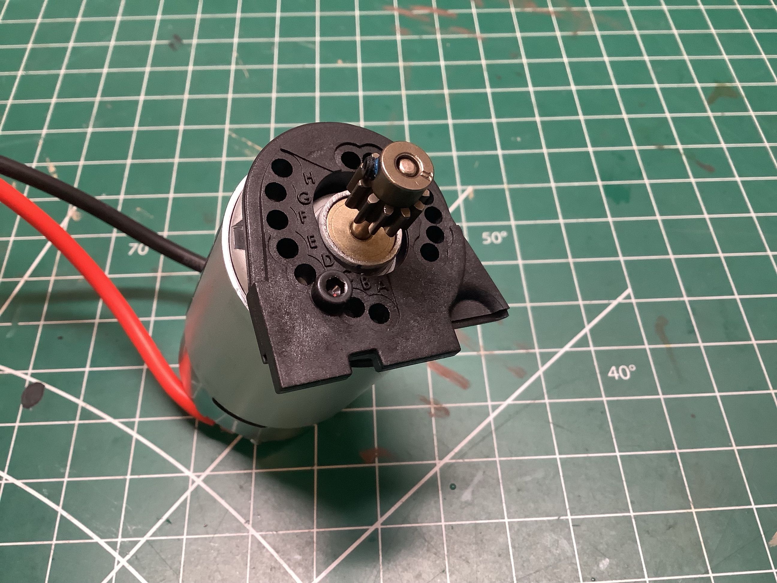
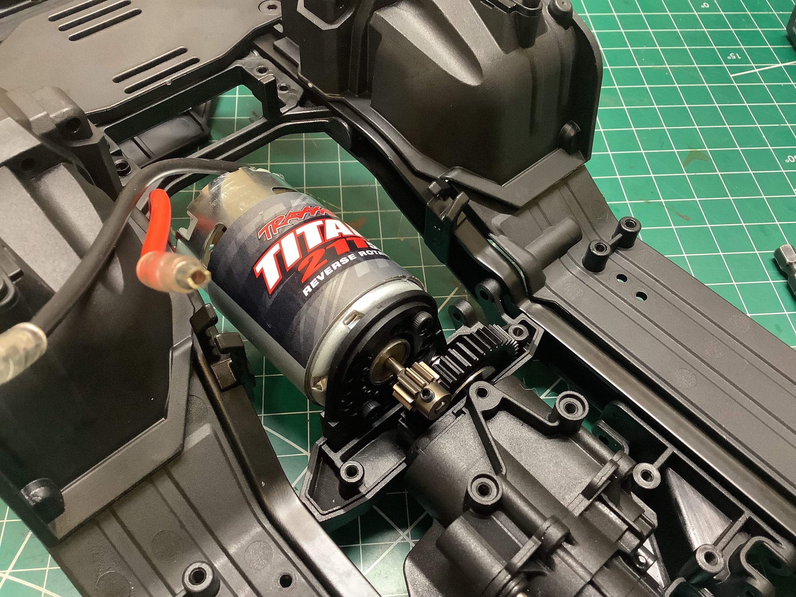
The plastic motor mount is indexed for pinion gears ranging from 9 to 16
teeth with the stock 45T spur, or from 15 to 22 teeth with the optional
39T spur. This results in motor reductions from 5:1 to 1.78:1, a
huge range. The stock pinion is 11 teeth, among the lowest speed
possible ratios. I'm not sure why anyone would want to make it
faster. It is already ridiculous on 3s in high gear. The
motor installs using a clever system that allows it to slot in from
above making it very easy to remove and almost impossible to mess up the
gear mesh.
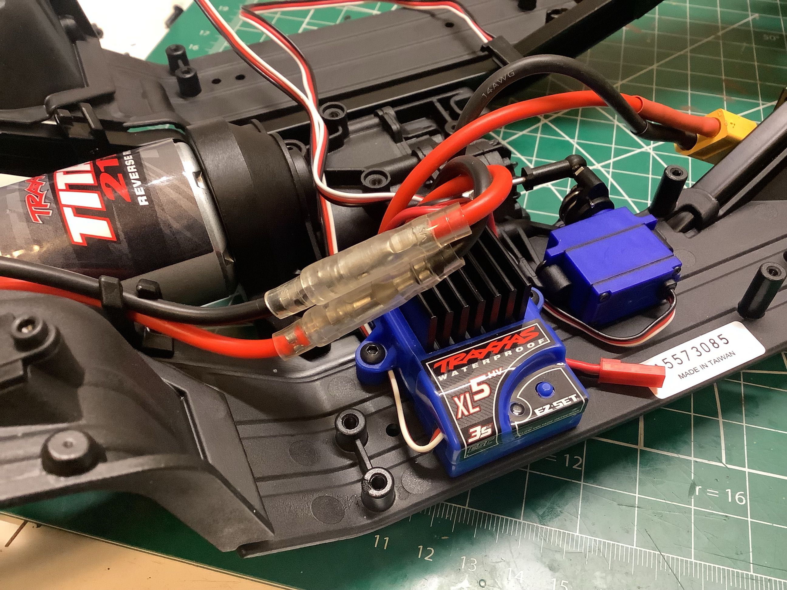
Here I've installed the steering servo. Traxxas calls it "High
Torque", but since that term has no definition it can mean
anything. It is passable for an RTR but not great. On the
right you can see that I've also installed the XL5 electronic speed
control This is a competent unit with drag brake and crawler mode
that operates smoothly at almost any rpm.
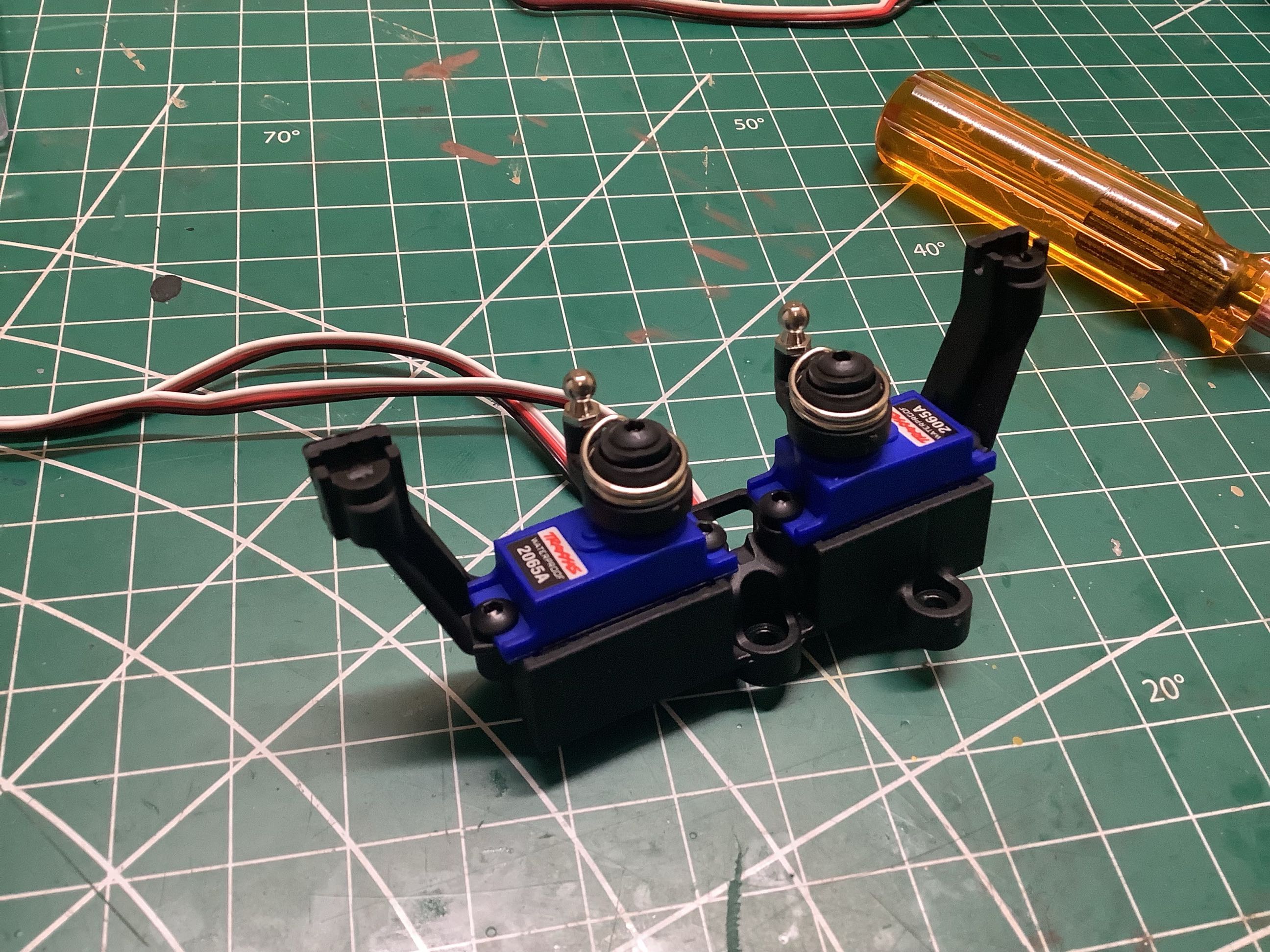
Here is bracket that holds the two micro servos to control the locking
of the front and rear differentials. Small servo savers are
integrated into the servo horns which are important since these servos
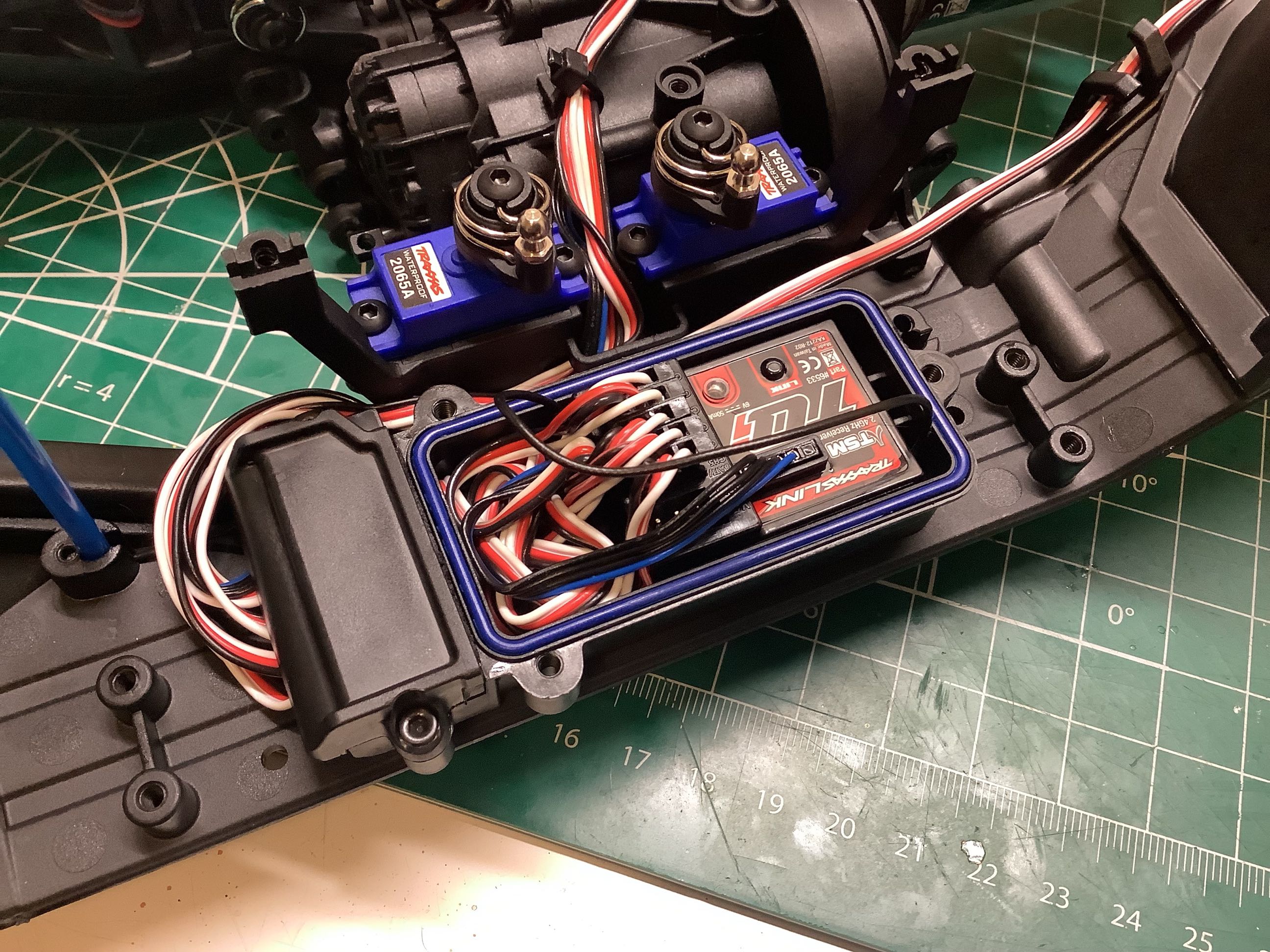
could spend a lot of time stalled against an external stop. On the
right you can see the very busy waterproof radio box. I almost
always replace the standard radio system with my Spektrum system, but in
this case I decided to keep the Traxxas system. This was
partially so I could operate the cruise control from the transmitter and
lighting through Bluetooth, but also so that I could trail with a
friend by letting them use a separate radio.
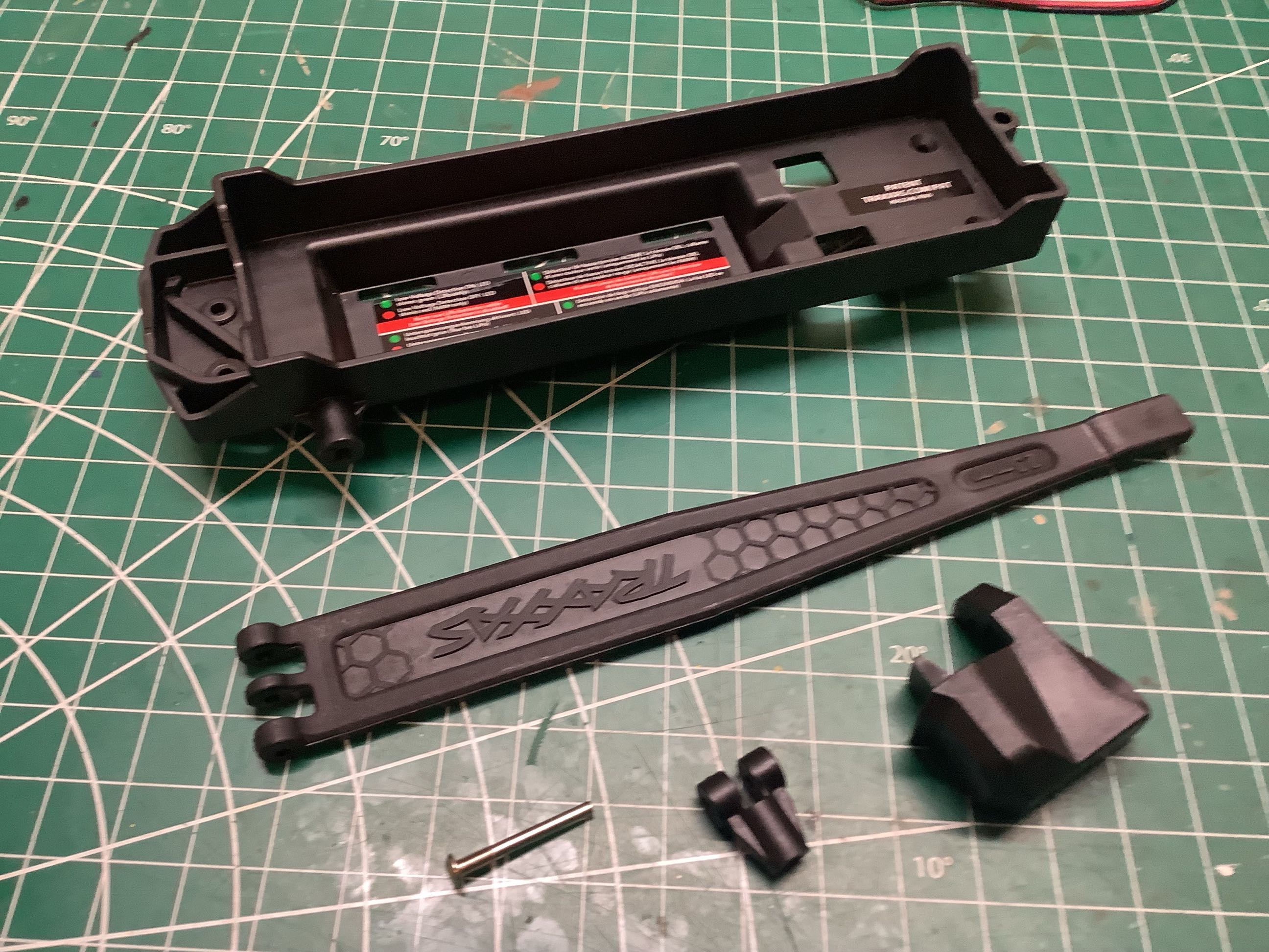
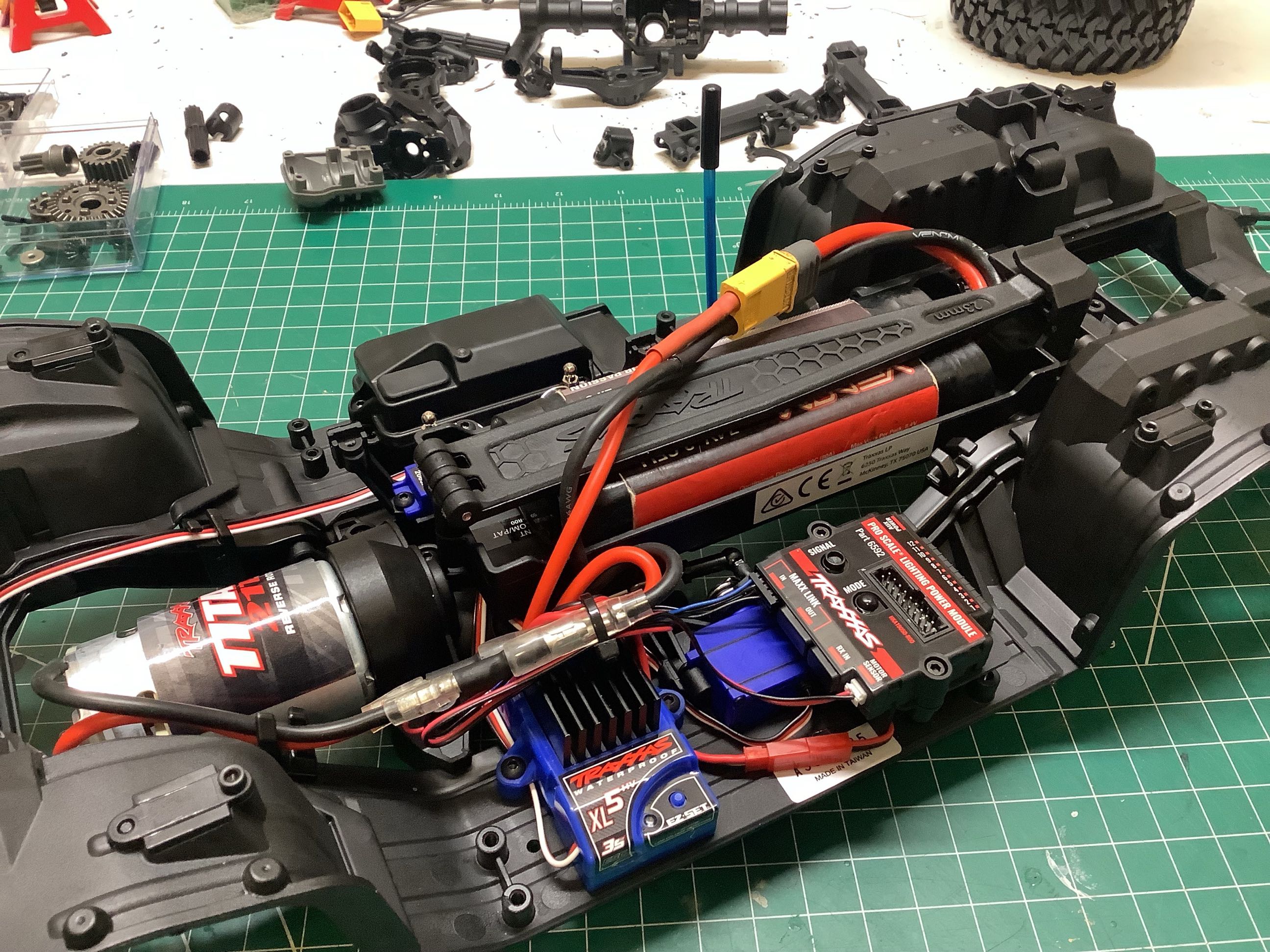
Here is the substantial battery track. The reversible hold down
lever allows firm retention of batteries of various thicknesses.
On the right the battery has been installed into the chassis so I could
try everything out. The battery is quite high which isn't great
for CG, but the optional tiny front battery tray can be used with a
smaller battery to move the CG forward and down.
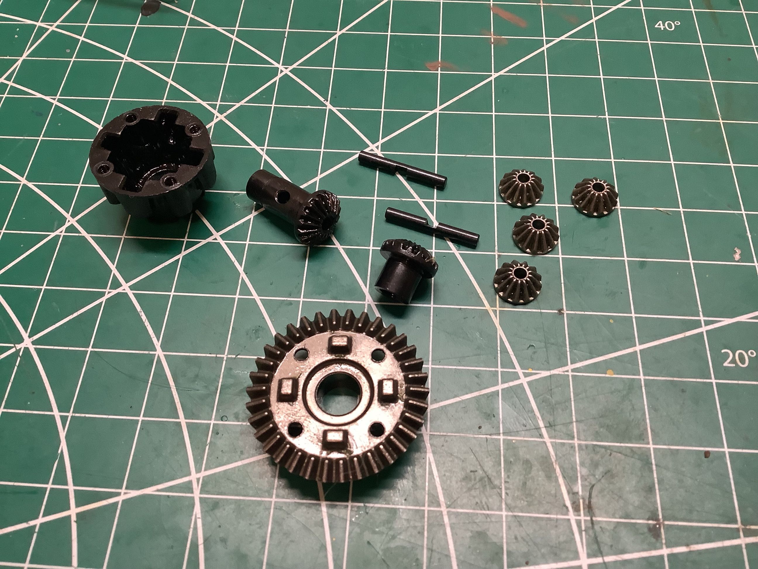
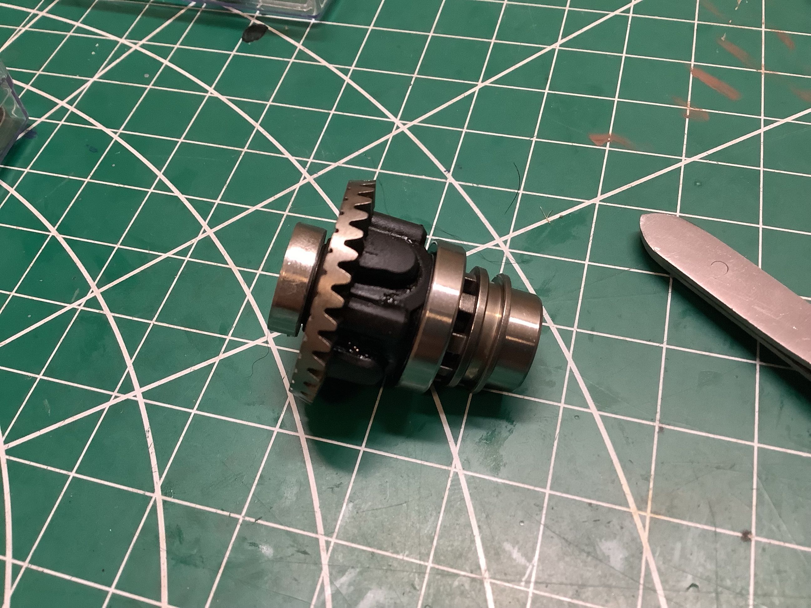
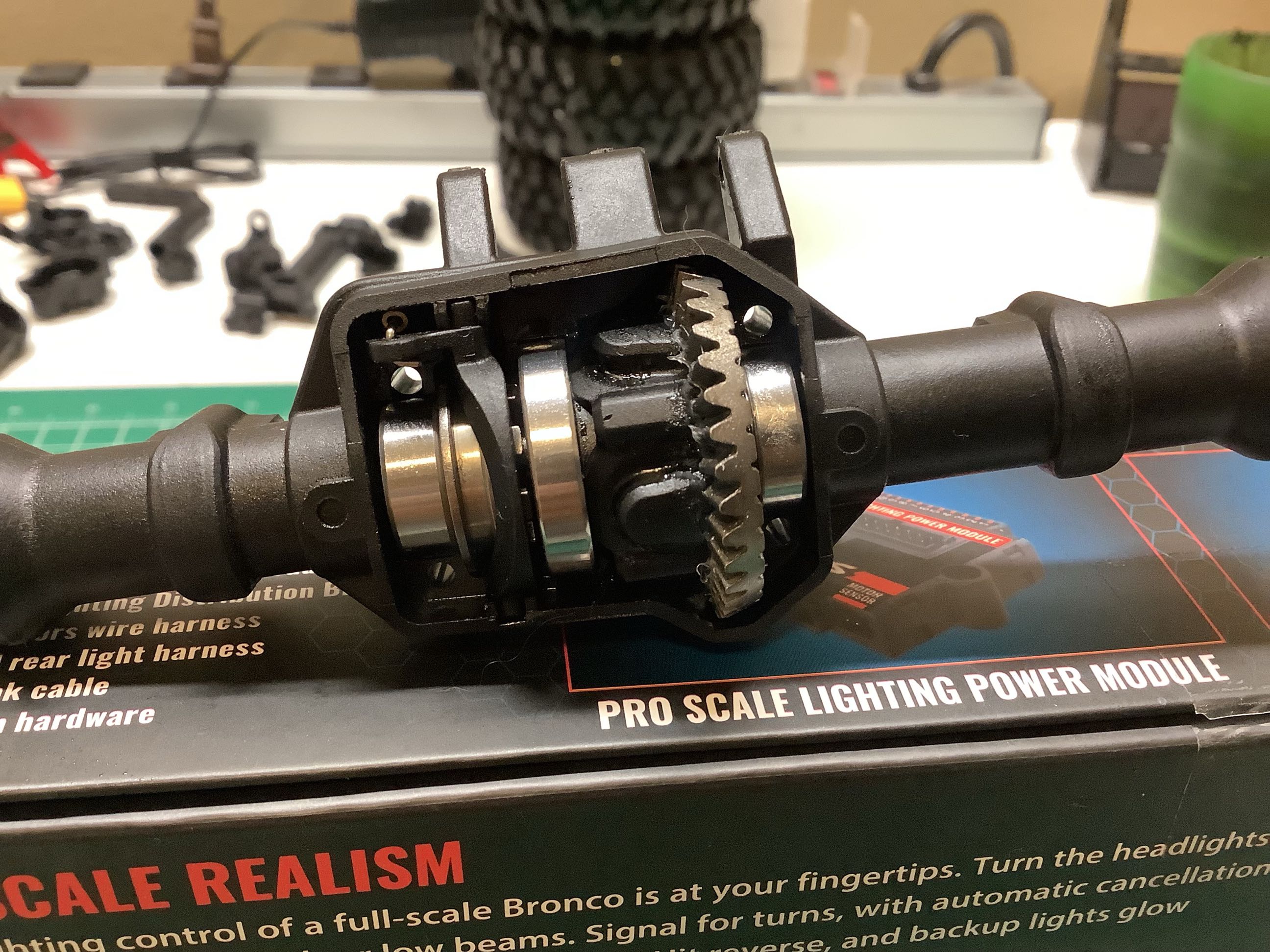
The TRX-4 is the first commercially successful chassis I can think of to
use remote locking differentials. The picture on the left shows
the standard differential components which include 4 metal spider
gears. On the right you can see the locking ring. When
engaged, the metal part connects the differential housing to one of the
output axles effectively locking the diff.
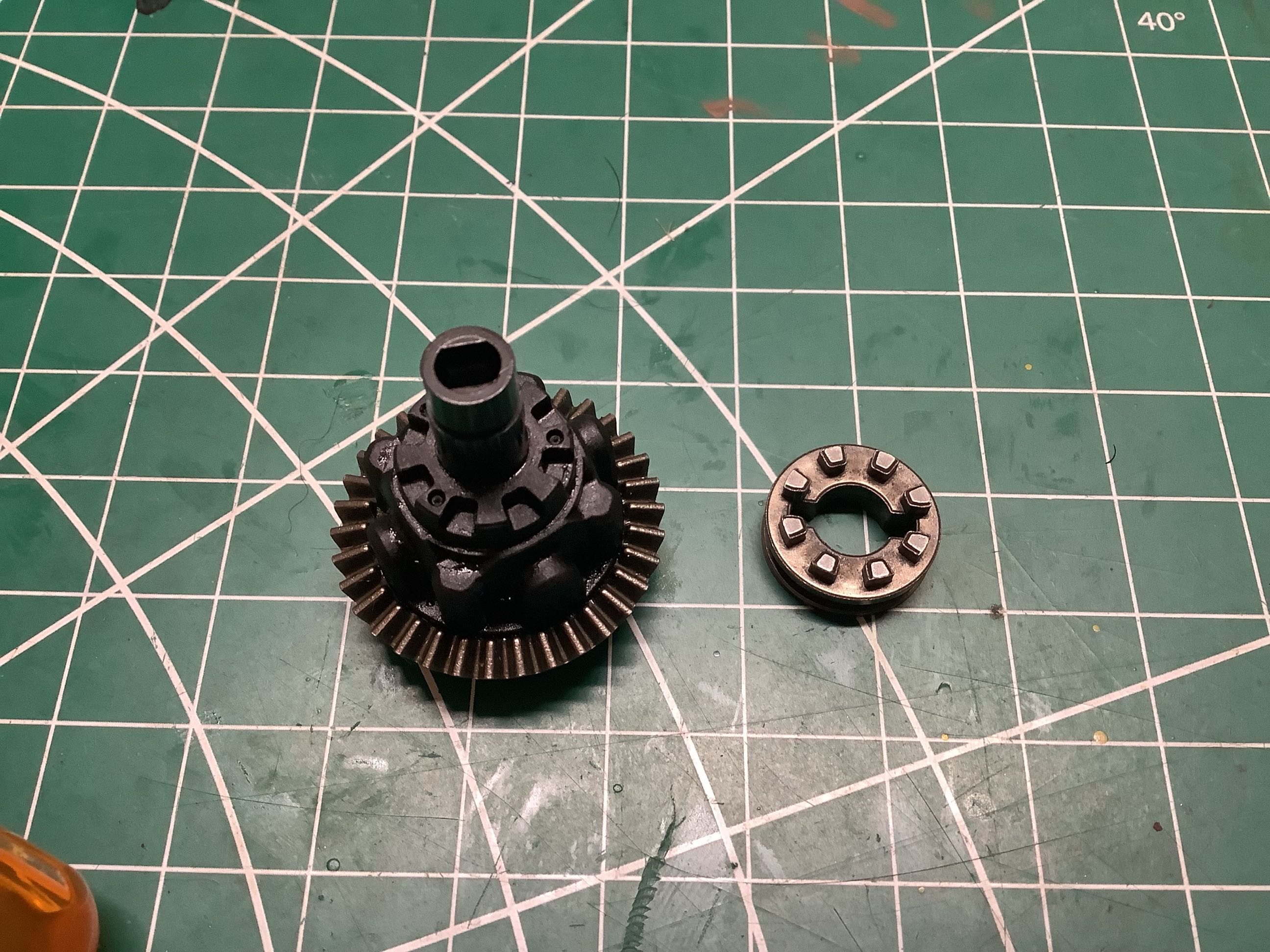
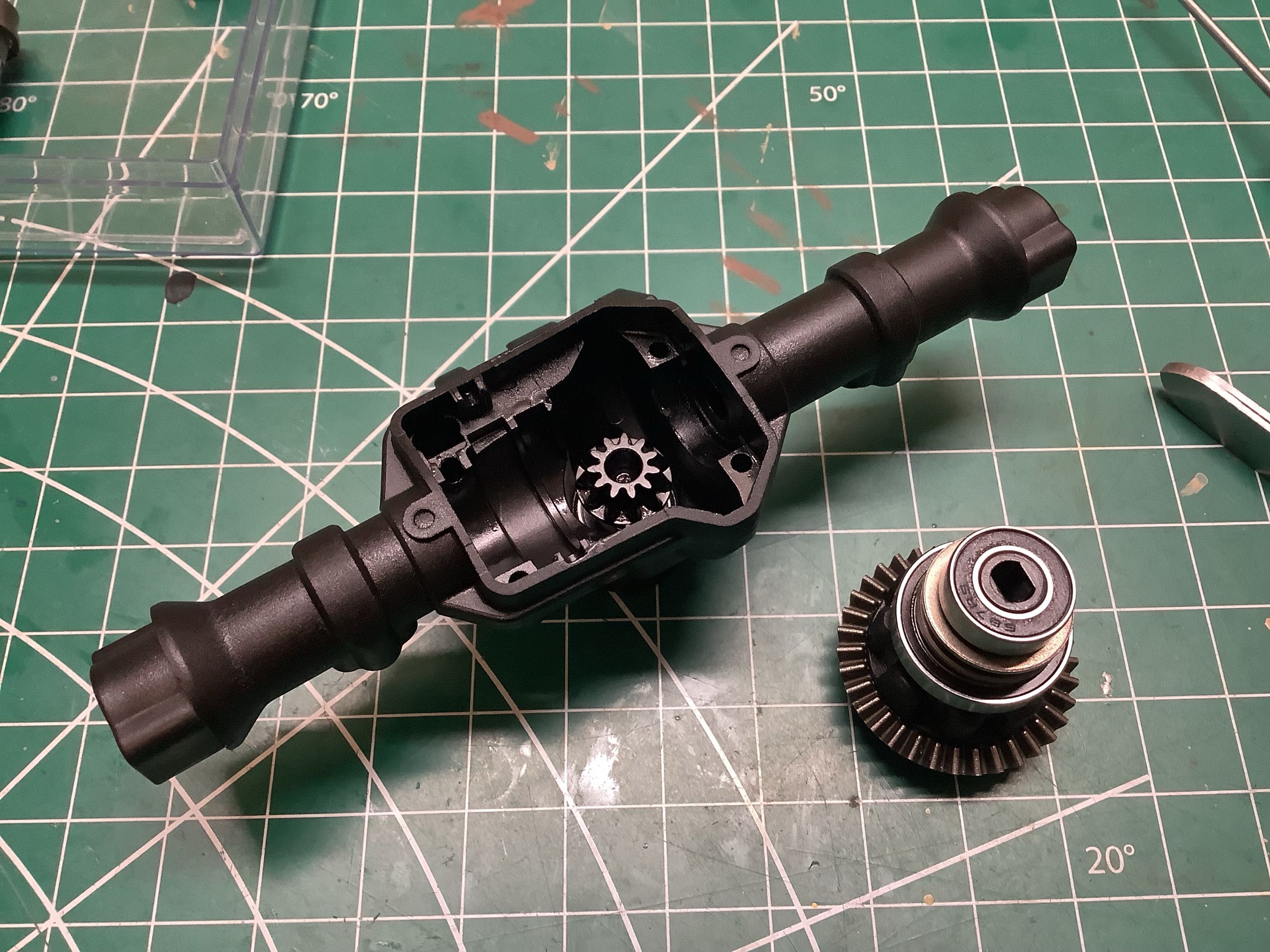
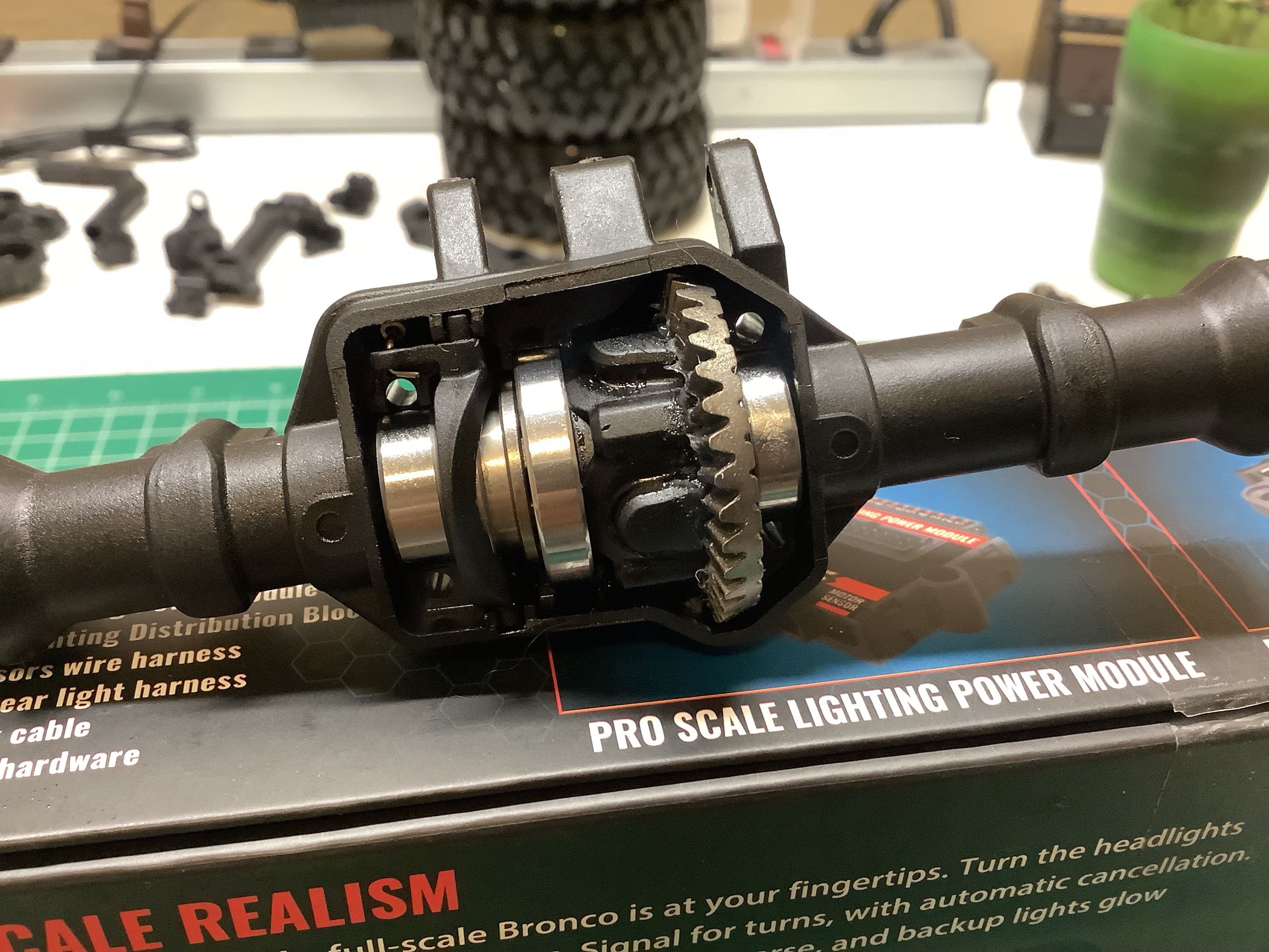
Here's a view of that locking mechanism installed. The metal part
on the right can translate along the axle. On the right you can
see the differential ready to install into the axle housing with the
pinion gear already in place. This model uses straight cut gears.
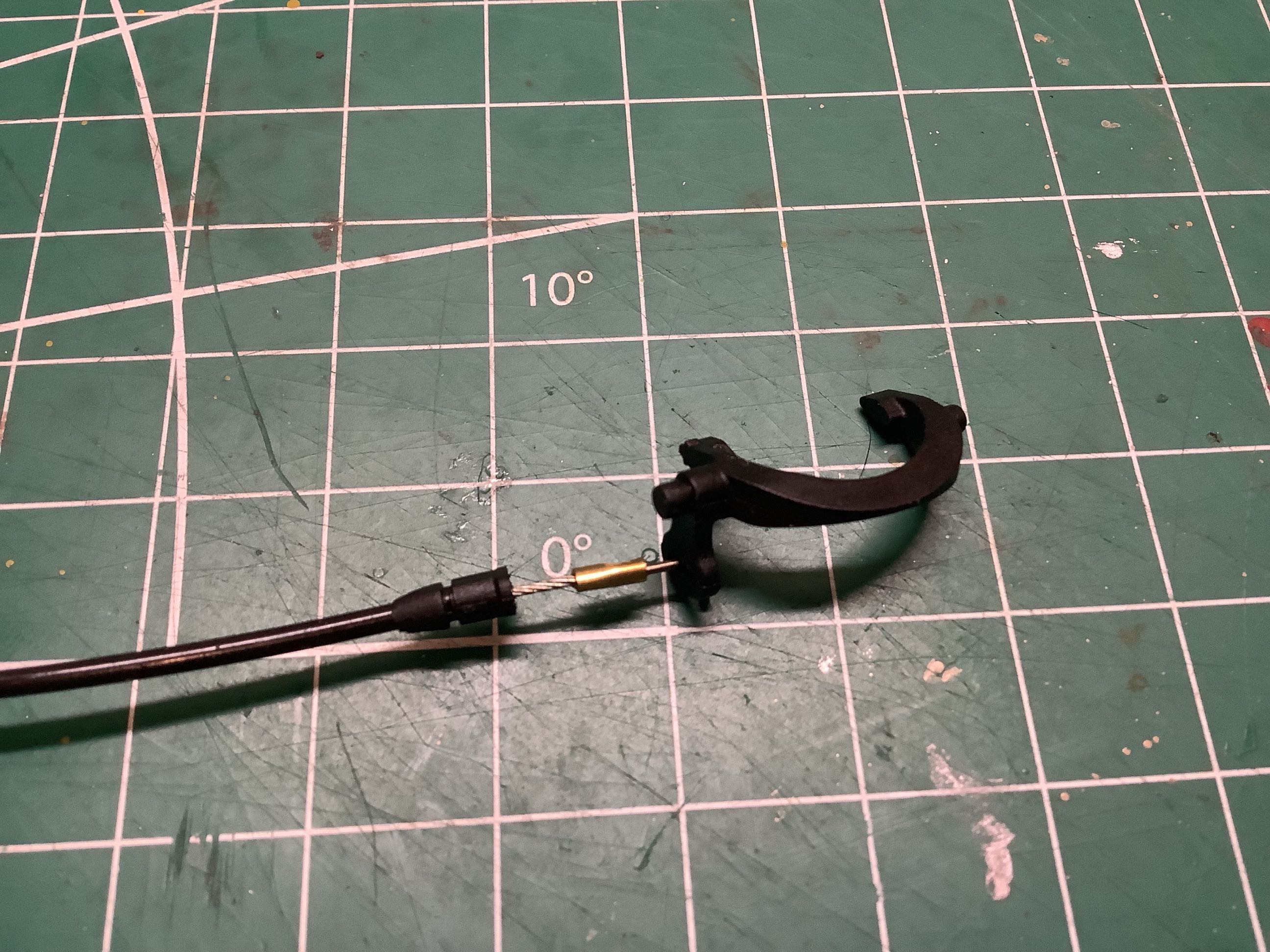
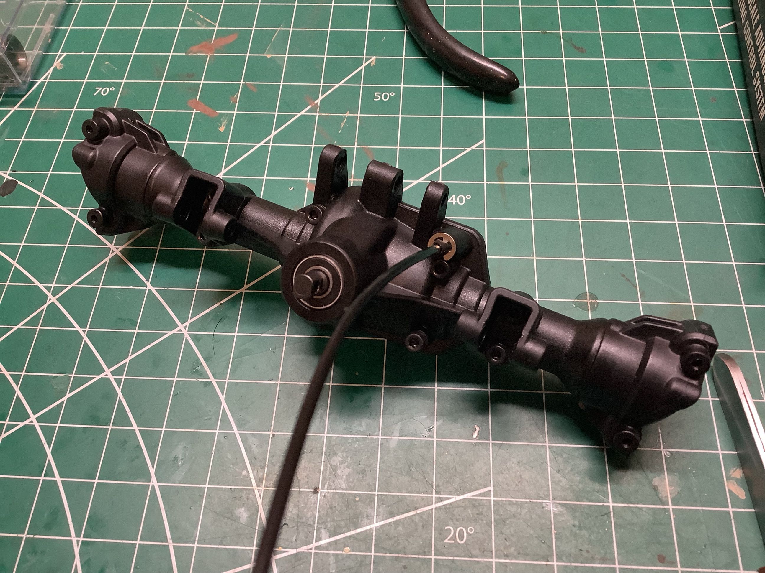
This is the cable operated fork used to actuate the differential locking
function. Cables are not always the strongest actuation
mechanisms, but I have to admit that I've never had any problem with
this particular implementation.
These pictures show the difference between a locked and unlocked
differential. The picture on the left is unlocked, the right is
locked.
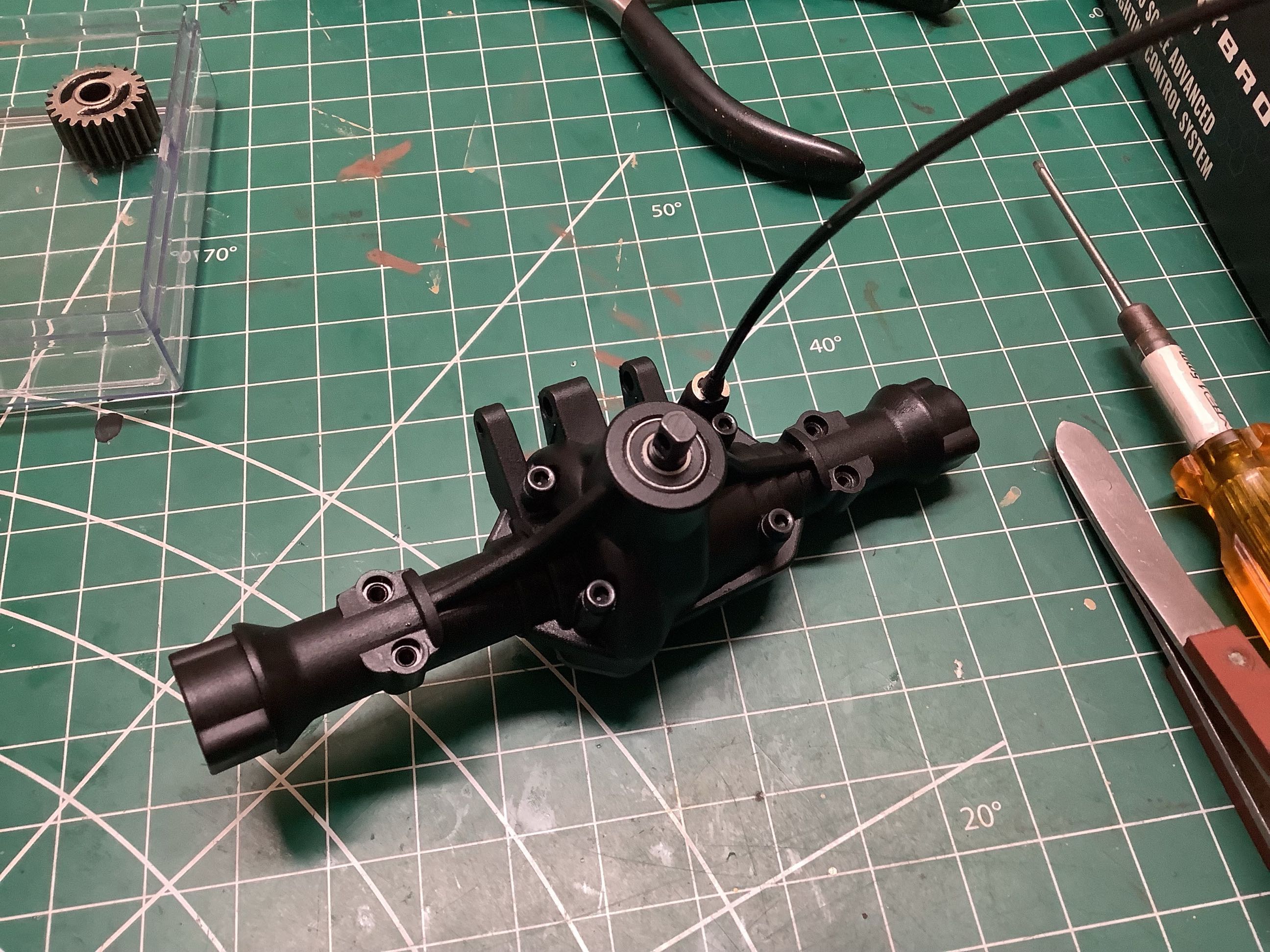
Now the diff cover has been installed and I can start working on the
portals. The picture on the left shows the outer straight portal
supports installed. On the right I've installed the portal
gearboxes. I didn't disassemble the rear, so see the front
assembly below for the internals of the portal boxes. This
completes the rear axle.
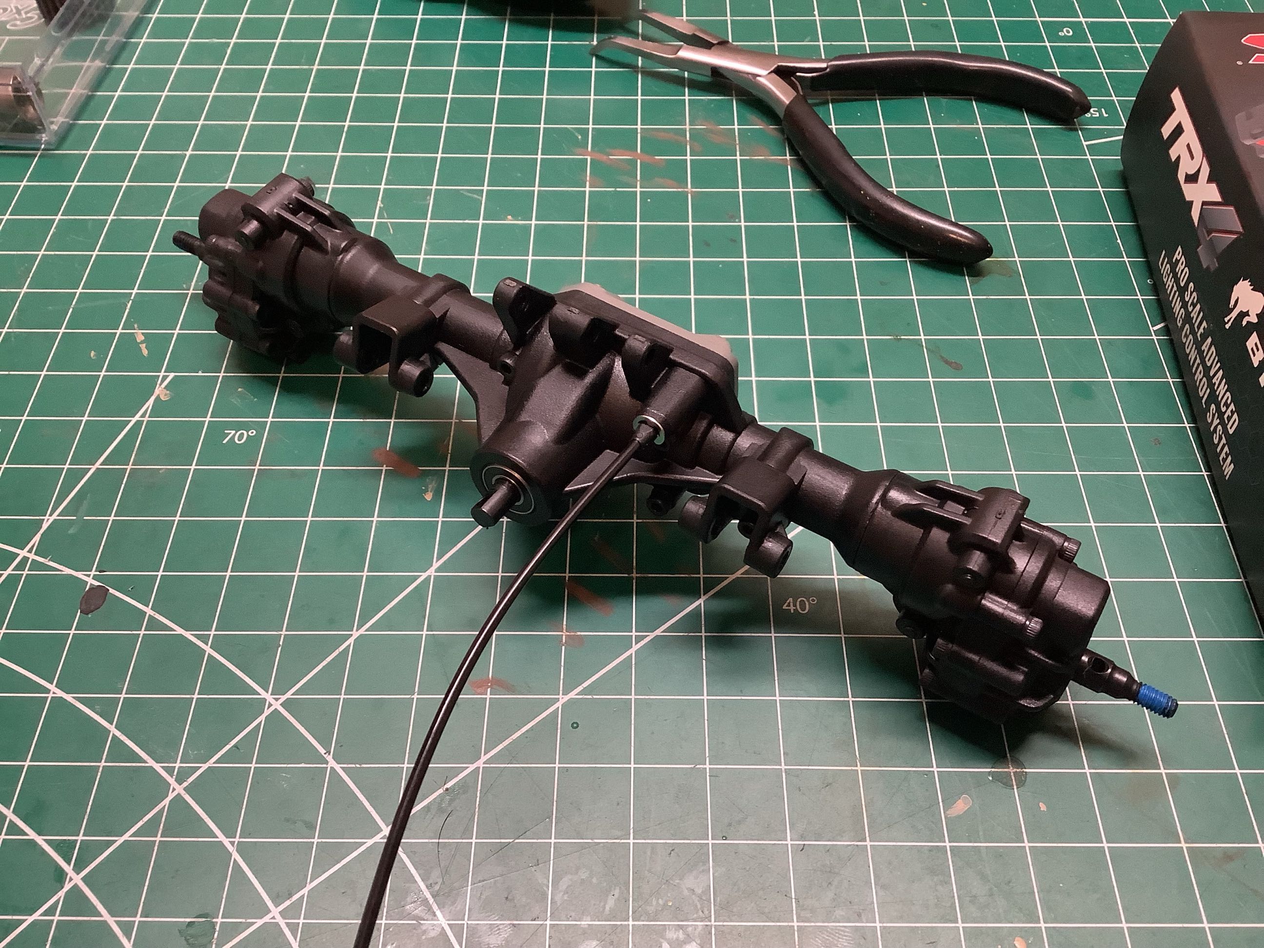
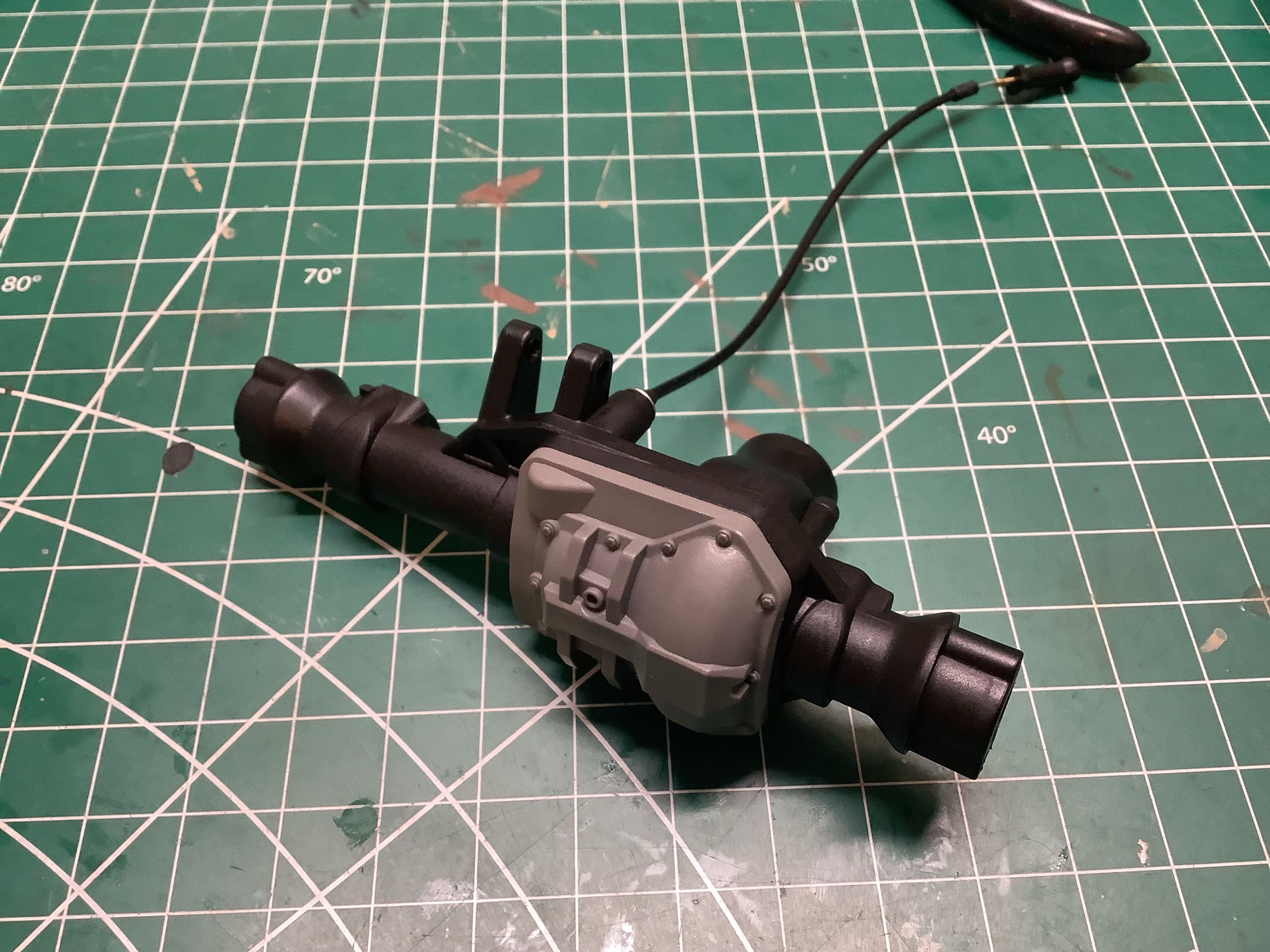
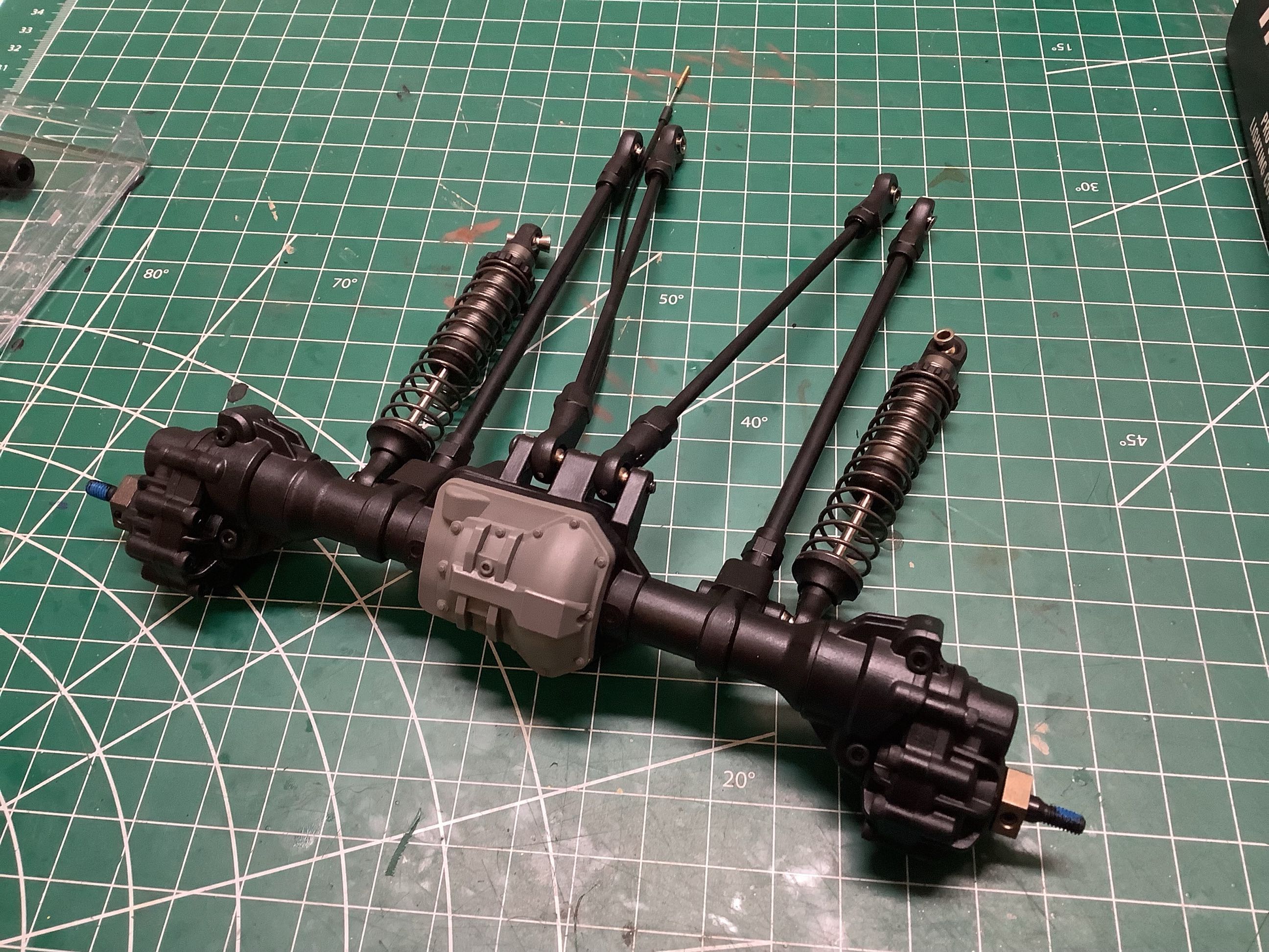
The center portion of the front axle is nearly the same as the rear, but
the differential is off center and the housing has attachments for a
panhard bar instead of a 4-link. The picture on the right shows
the housings for the front steerable portals.
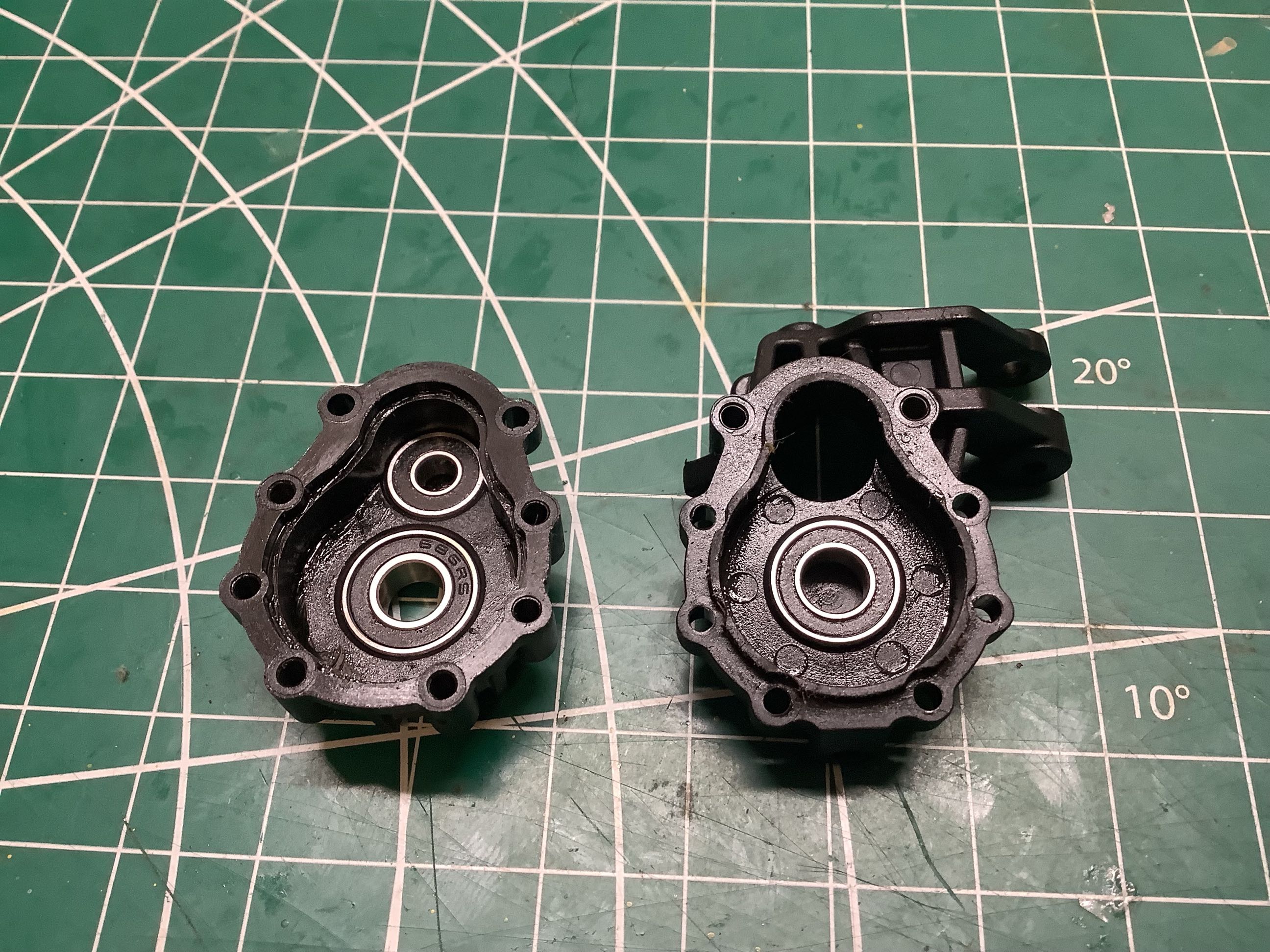
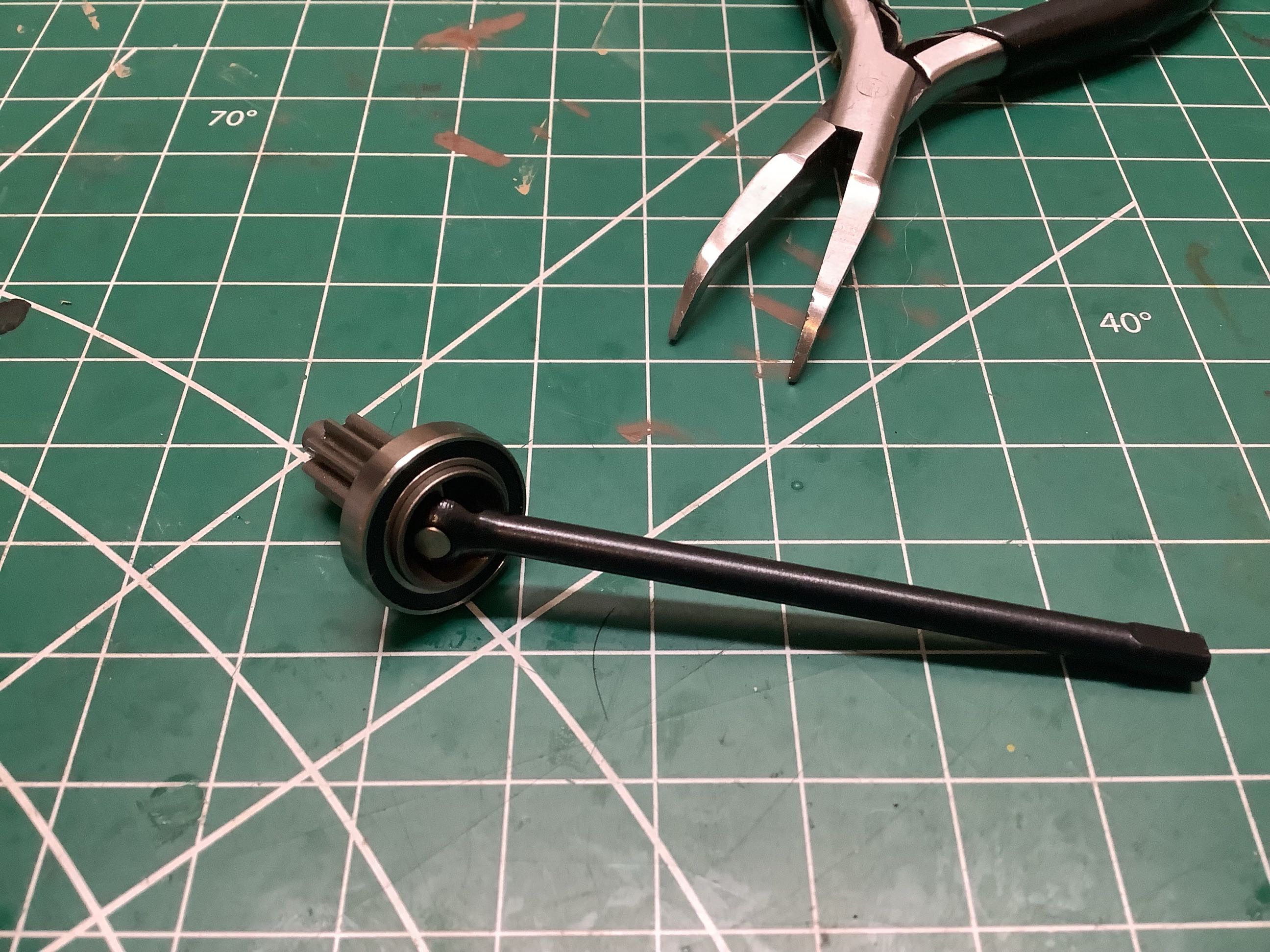
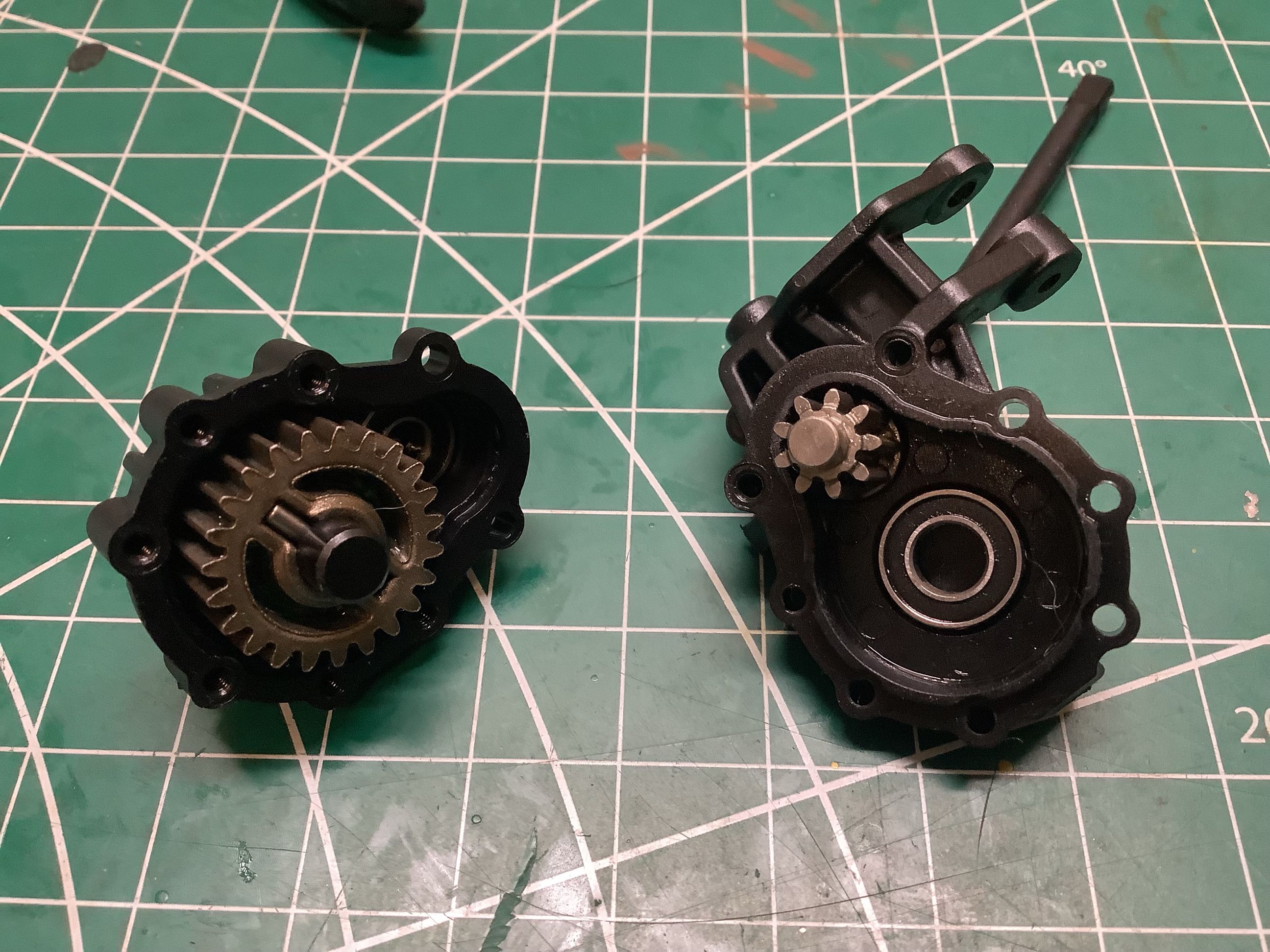
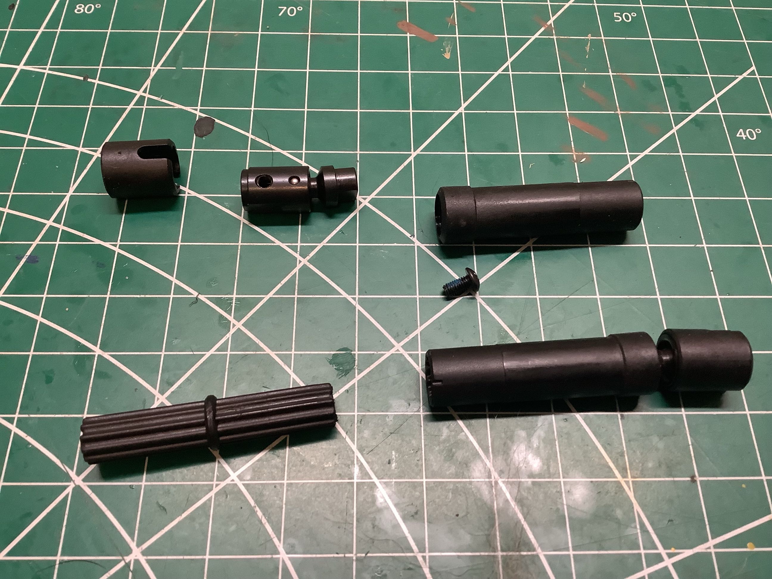
The front axle is a CVD style with a gear at the end as shown. In
the right picture you can see this gear protruding into the portal
housing (far upper right). This portal box does not use any idler
gears; the axle directly drives a larger output gear resulting in a
reversal of rotation direction. The portals have a 2.56:1 (23:9)
reduction.
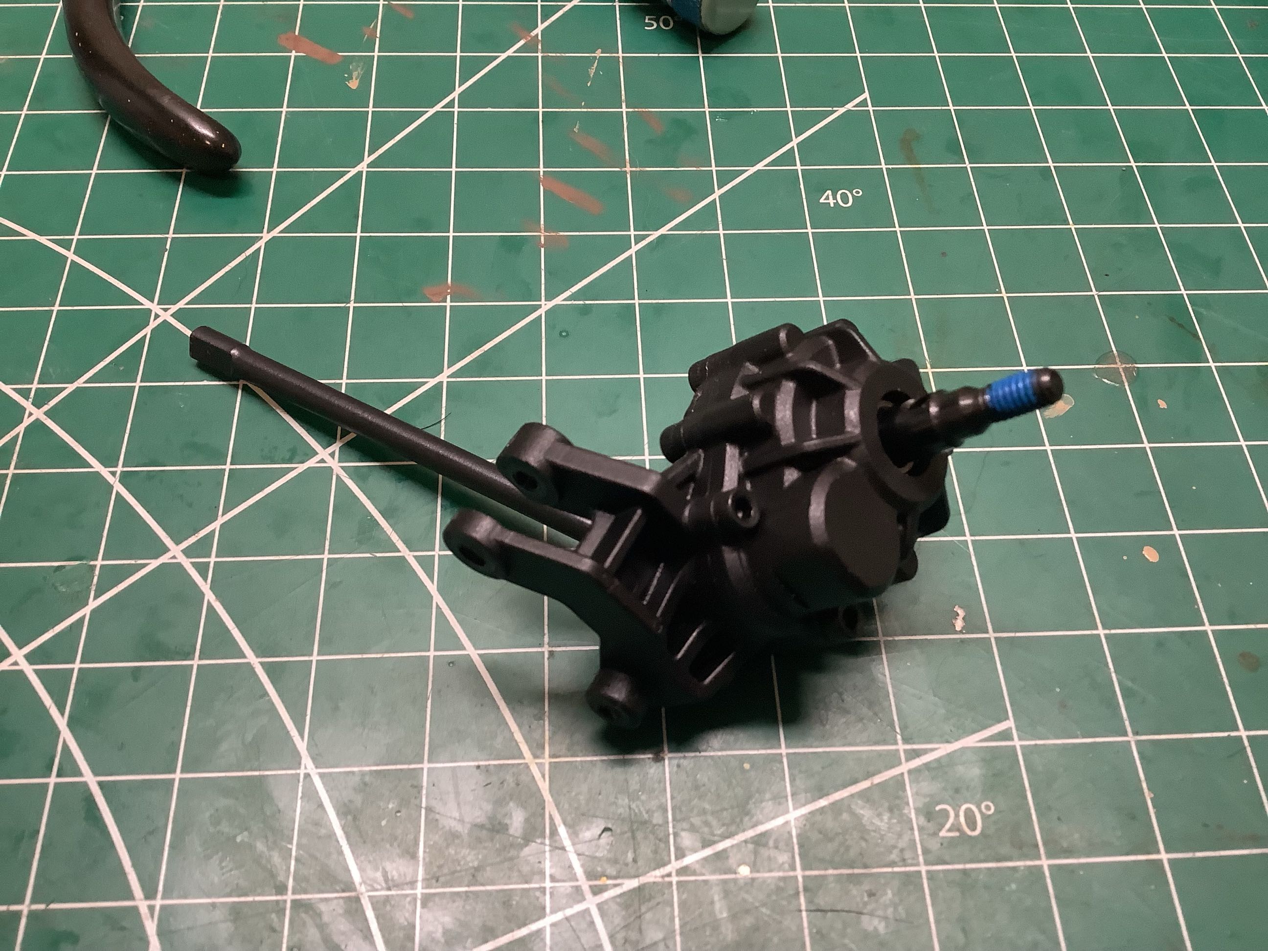
Here is the completed front portal box both separately and installed on
the axle. Note the very large amount of space consumed by the
portal box which limits the type and offset of the wheels that can be
used. The front kingpin inclination is clearly visible.
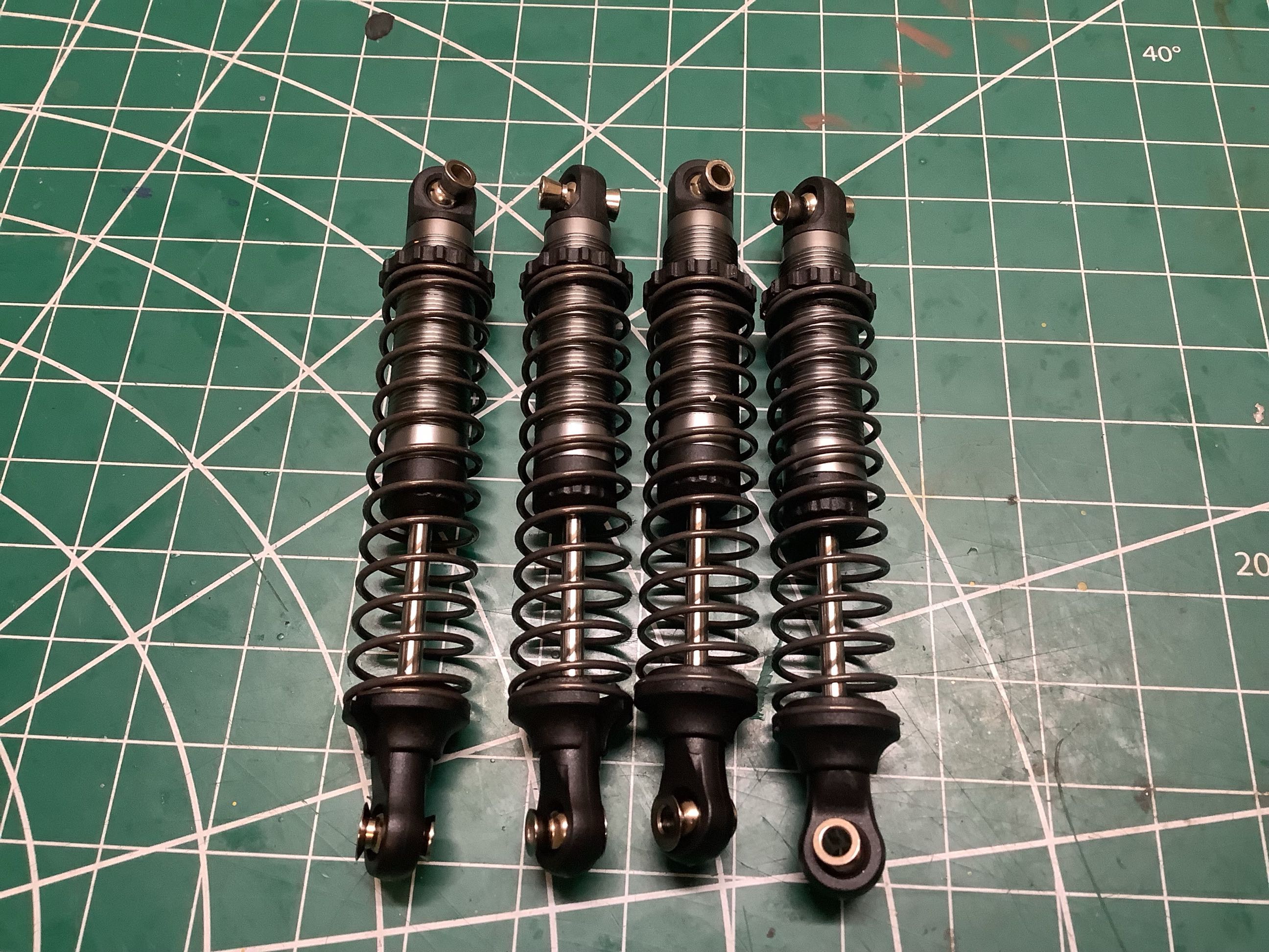
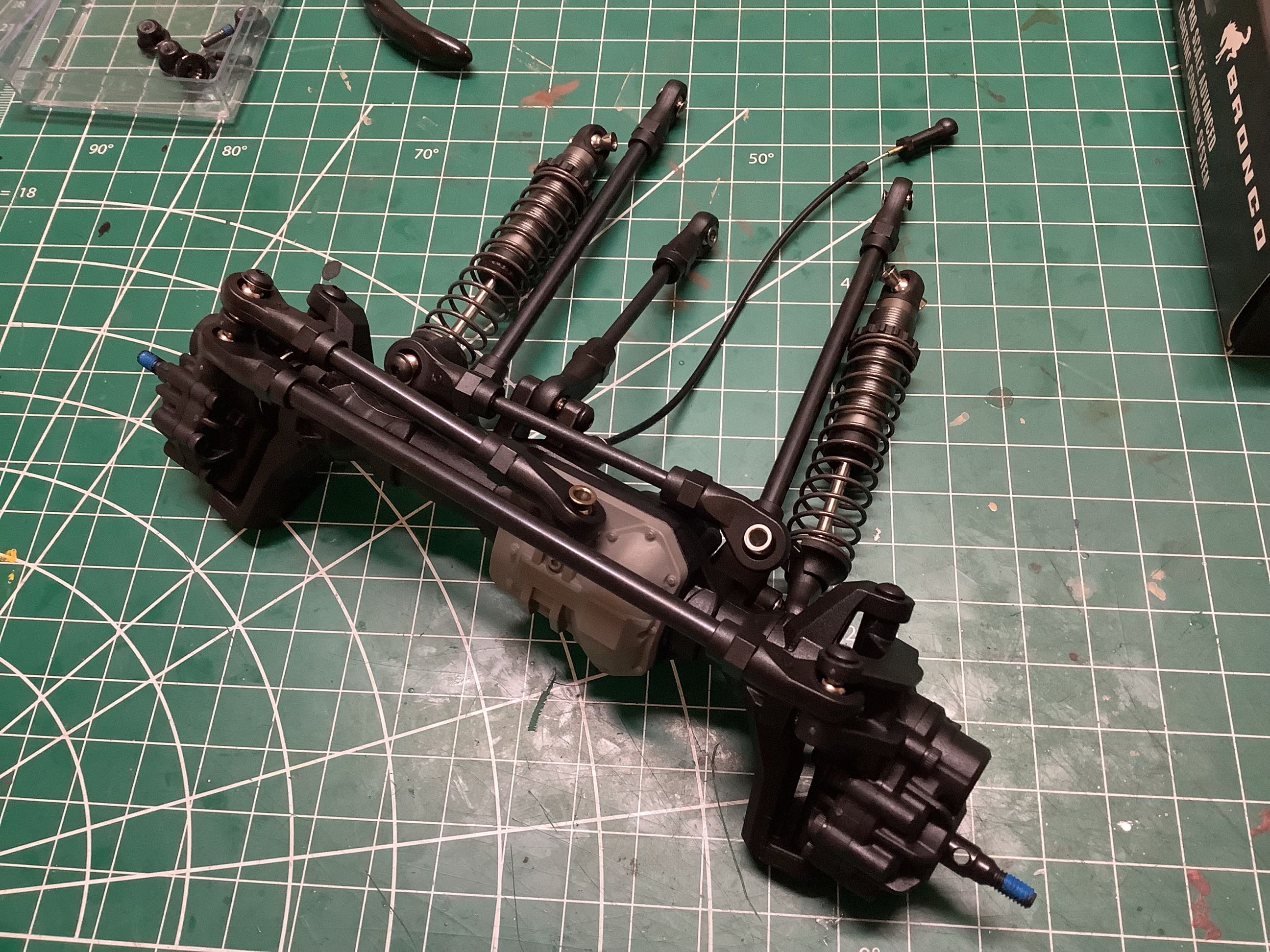
Here are the shocks which I did not take apart. They are
relatively small diameter (which is scale accurate) with aluminum bodies
and adjustment collars. The drive shaft are plastic bodied with
metal universals.
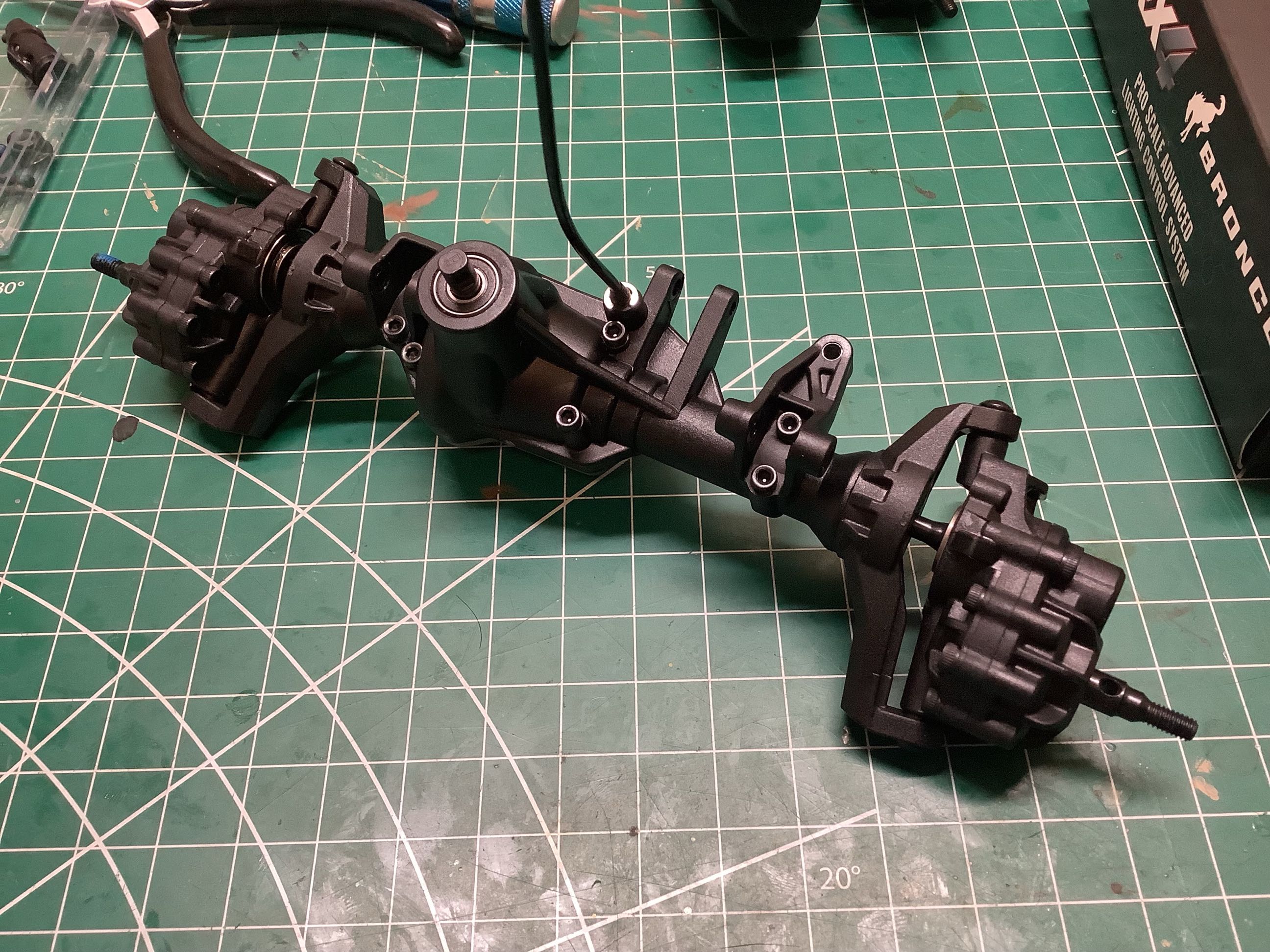
Here I've added all the links and shocks to the axles. The links
are metal with plastic ends and steel balls. The front axle is
shown on the left and the rear on the right.
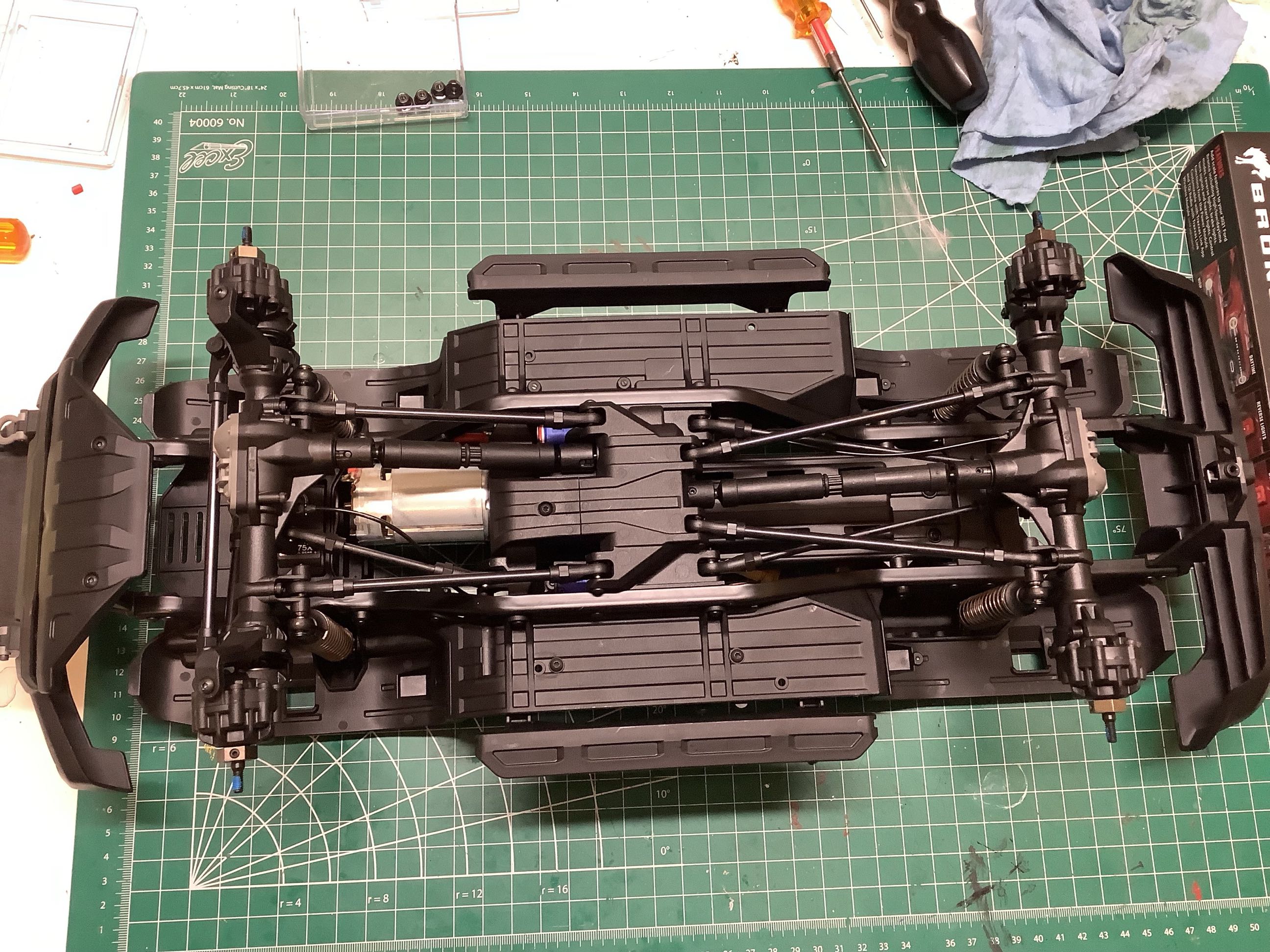
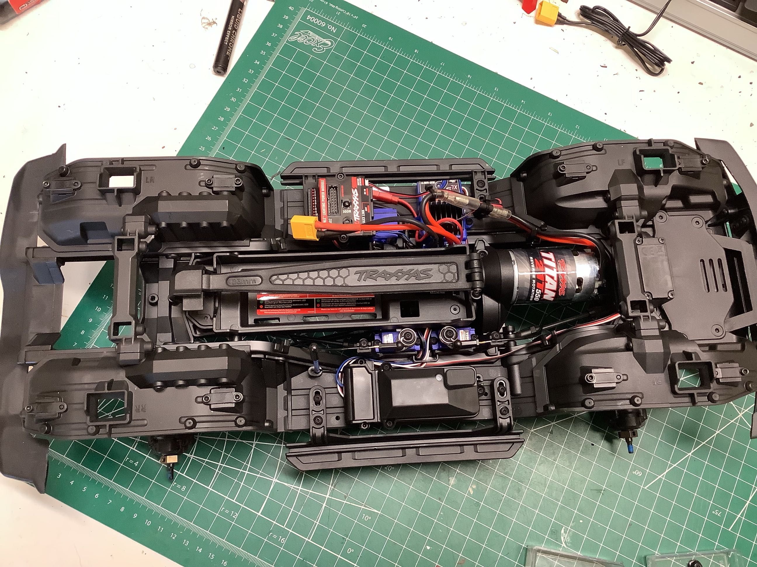
The final step is to connect the axles to the chassis with a handful of
bolts. These pictures show the completed chassis from above and
below. Everything is very neat and tidy with carefully planned
wire routing using hold down clips. Maintenance access in general
is excellent.
©2022 Eric Albrecht