Tamiya Asterion Project
Page 1: Assembly
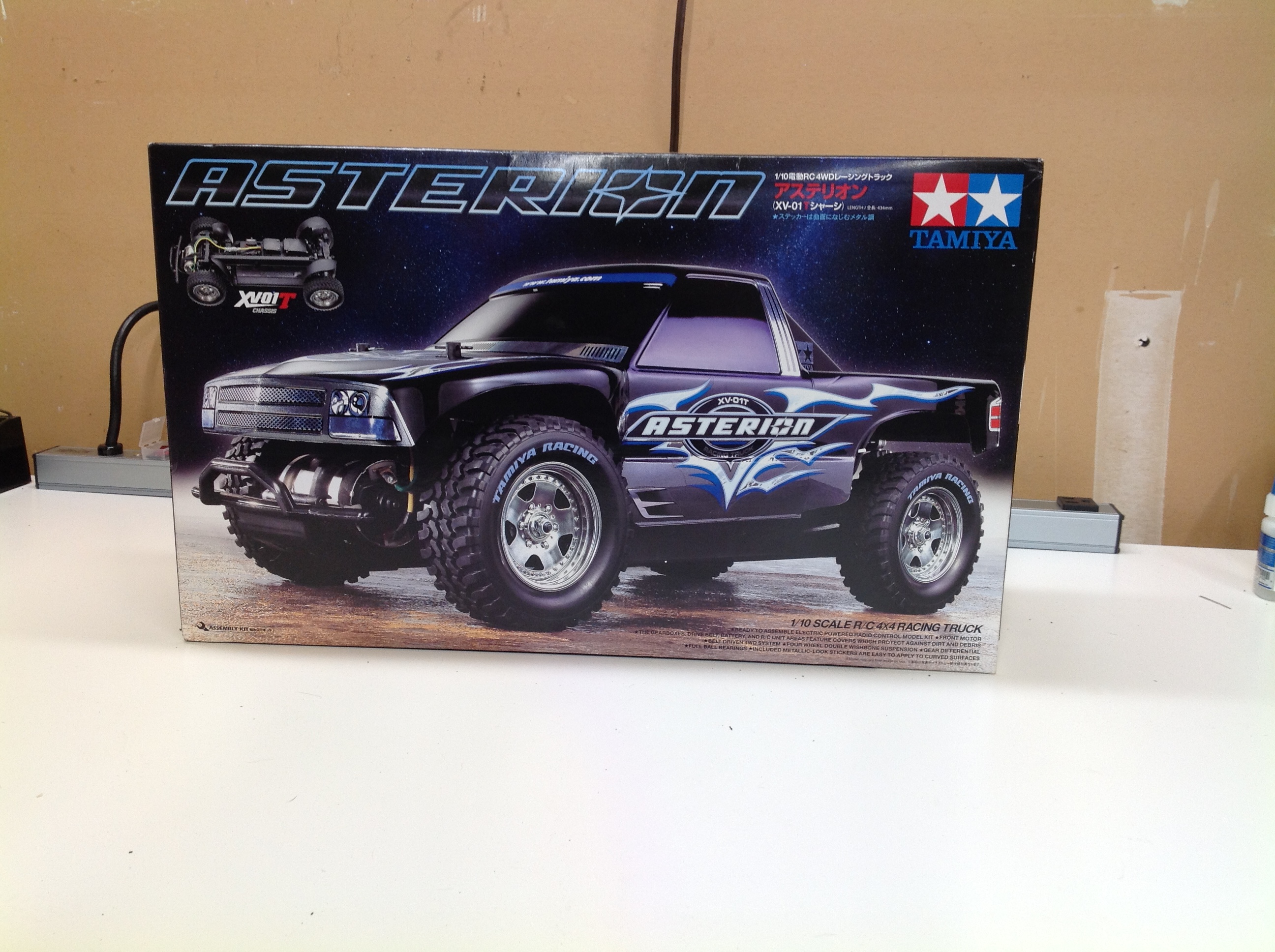
Here's the box. Unlike many Tamiya kits, it uses an actual
photograph instead of the usual hand drawn art. I prefer the old
way, but this is a pretty good looking truck regardless.
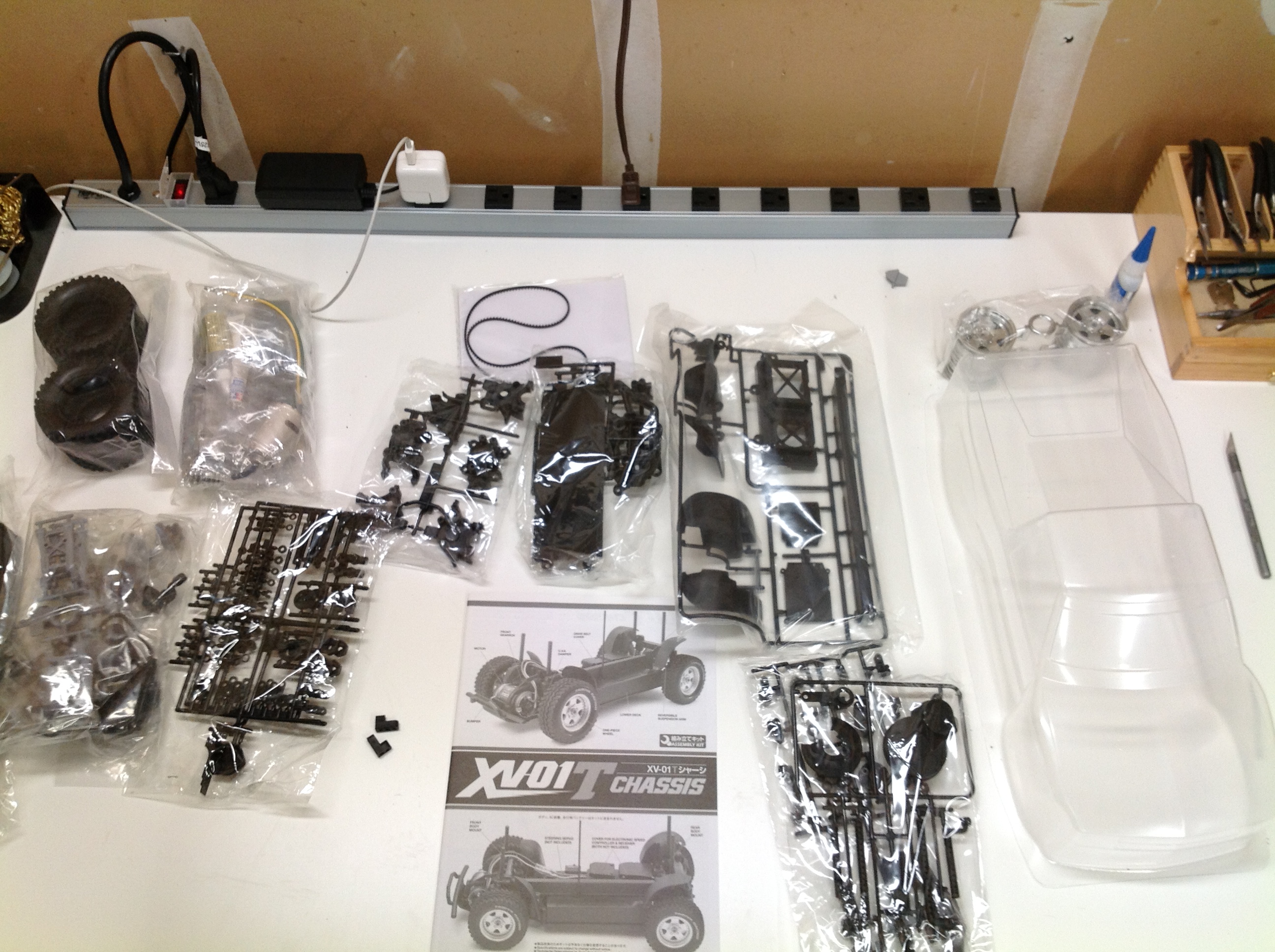
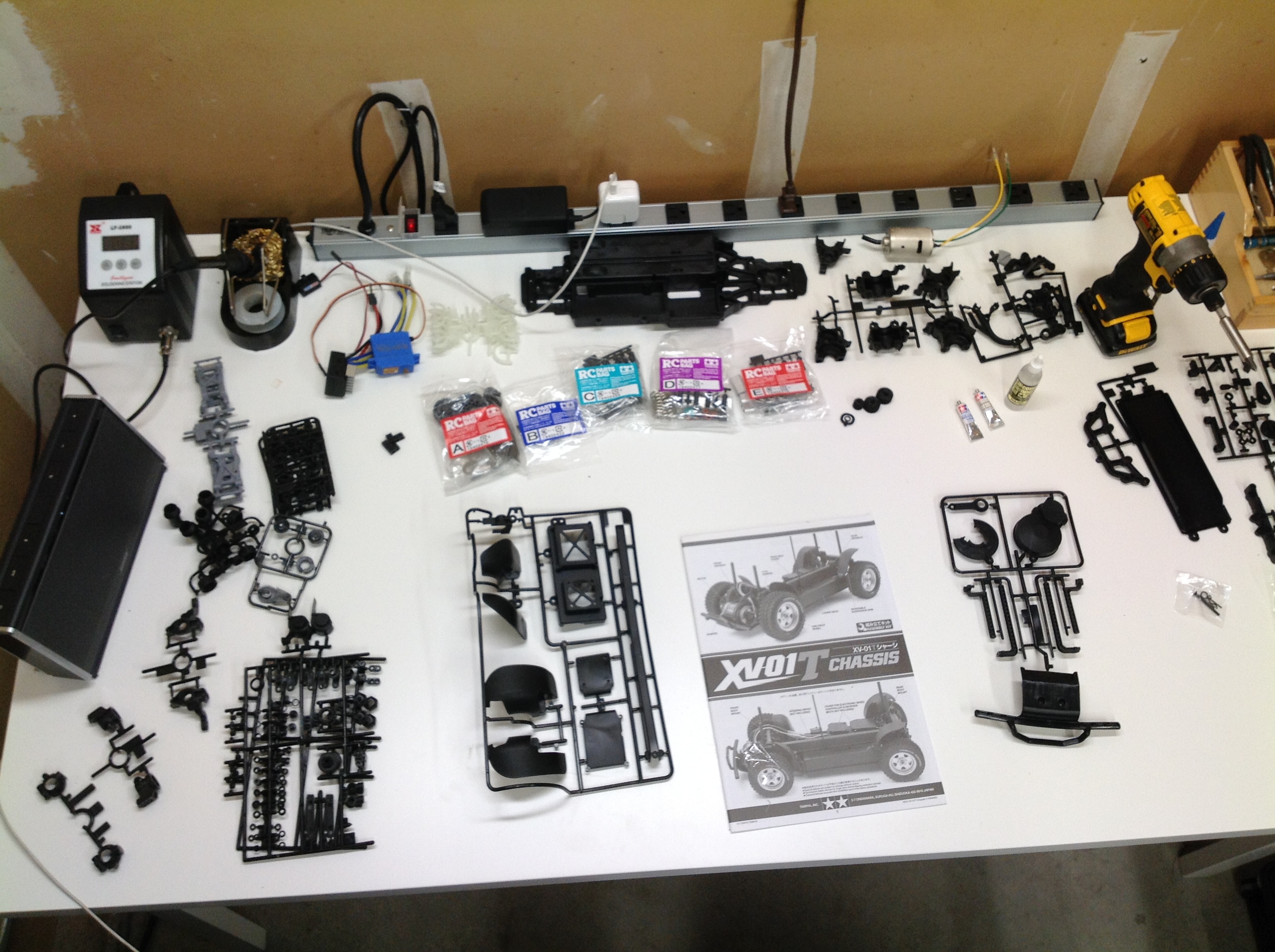
There was a lot of stuff in that little box! The first image shows
everything unpacked in the way it is grouped in the box. The
second image unpacks the bags of plastic parts trees and separates
them. There are also five labelled hardware bags which correspond
to portions of the instructions.
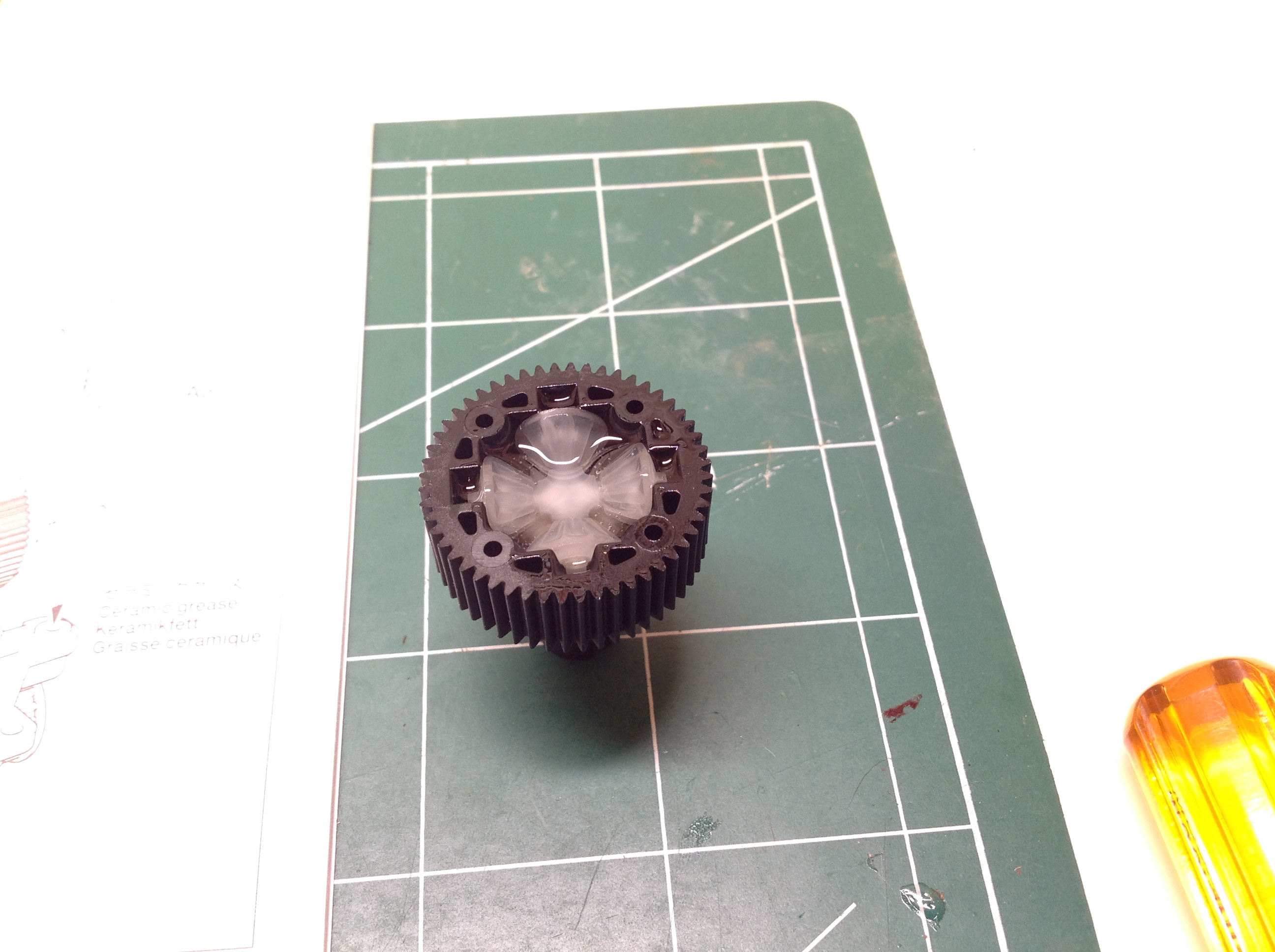
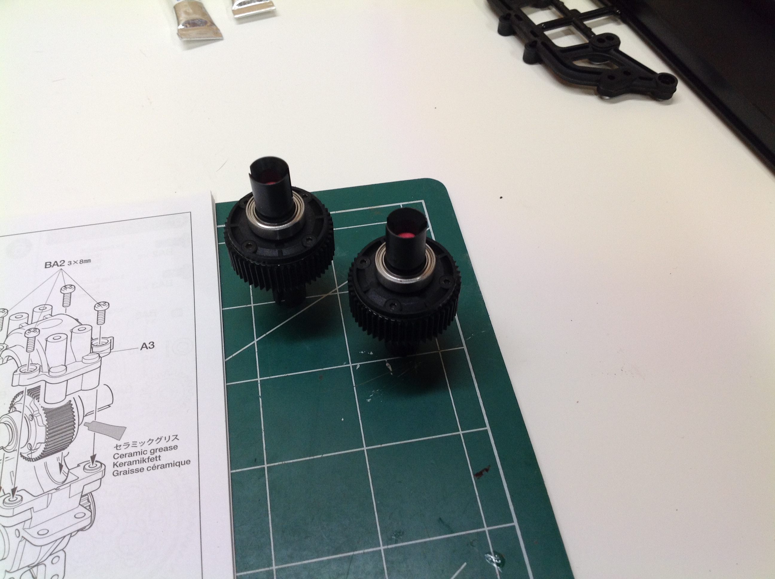
The model uses sealed gear diffentials with plastic bevel gears.
The diff fluid is the clear "hard" variety from Tamiya which is also
used for the shocks. The front and rear differential are
identical.
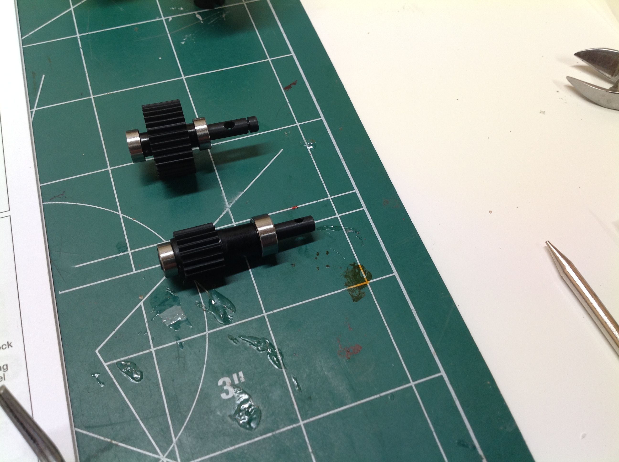
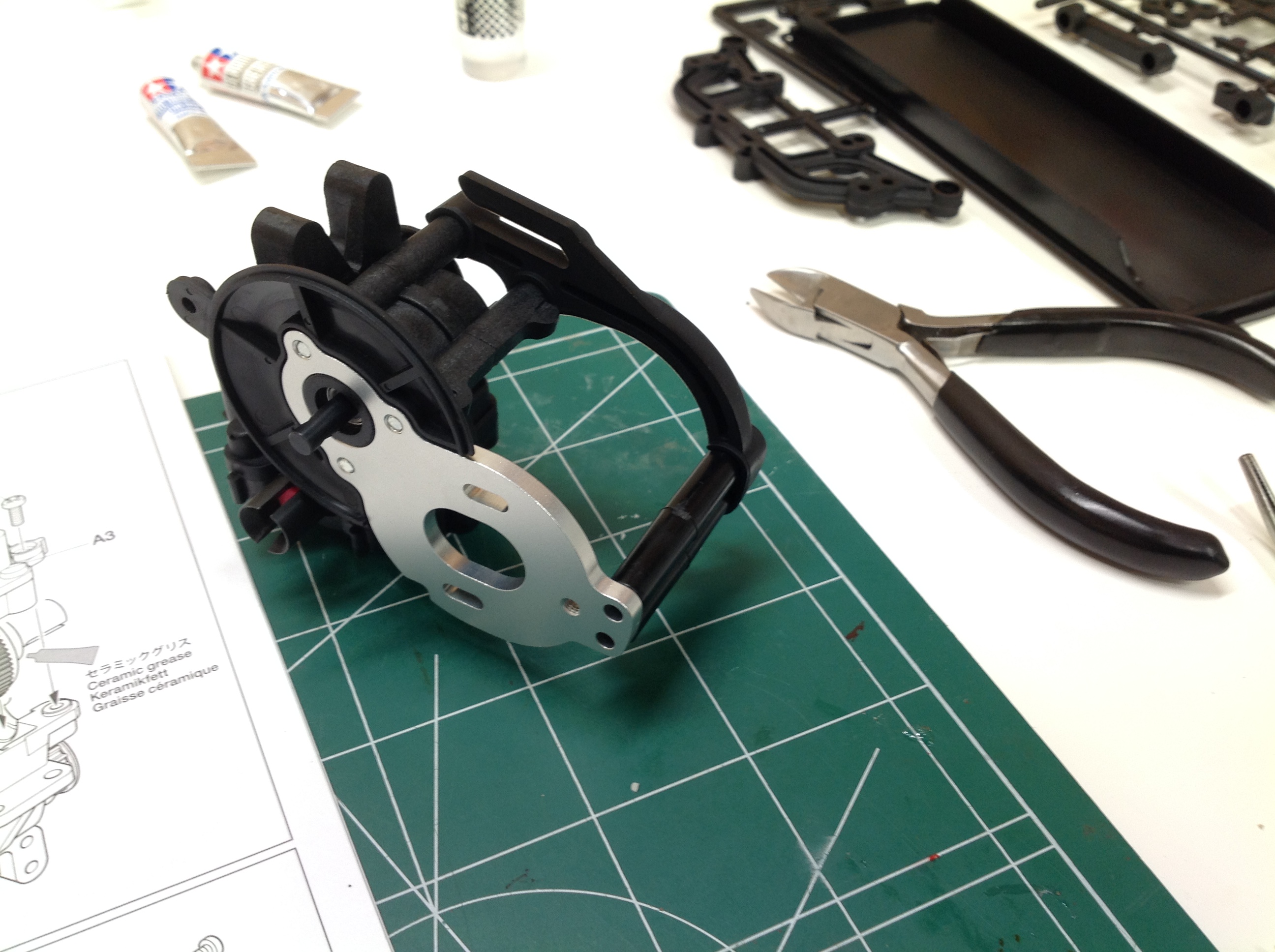
These geared shafts are for the transmission which will be located ahead of the front axle with the motor.
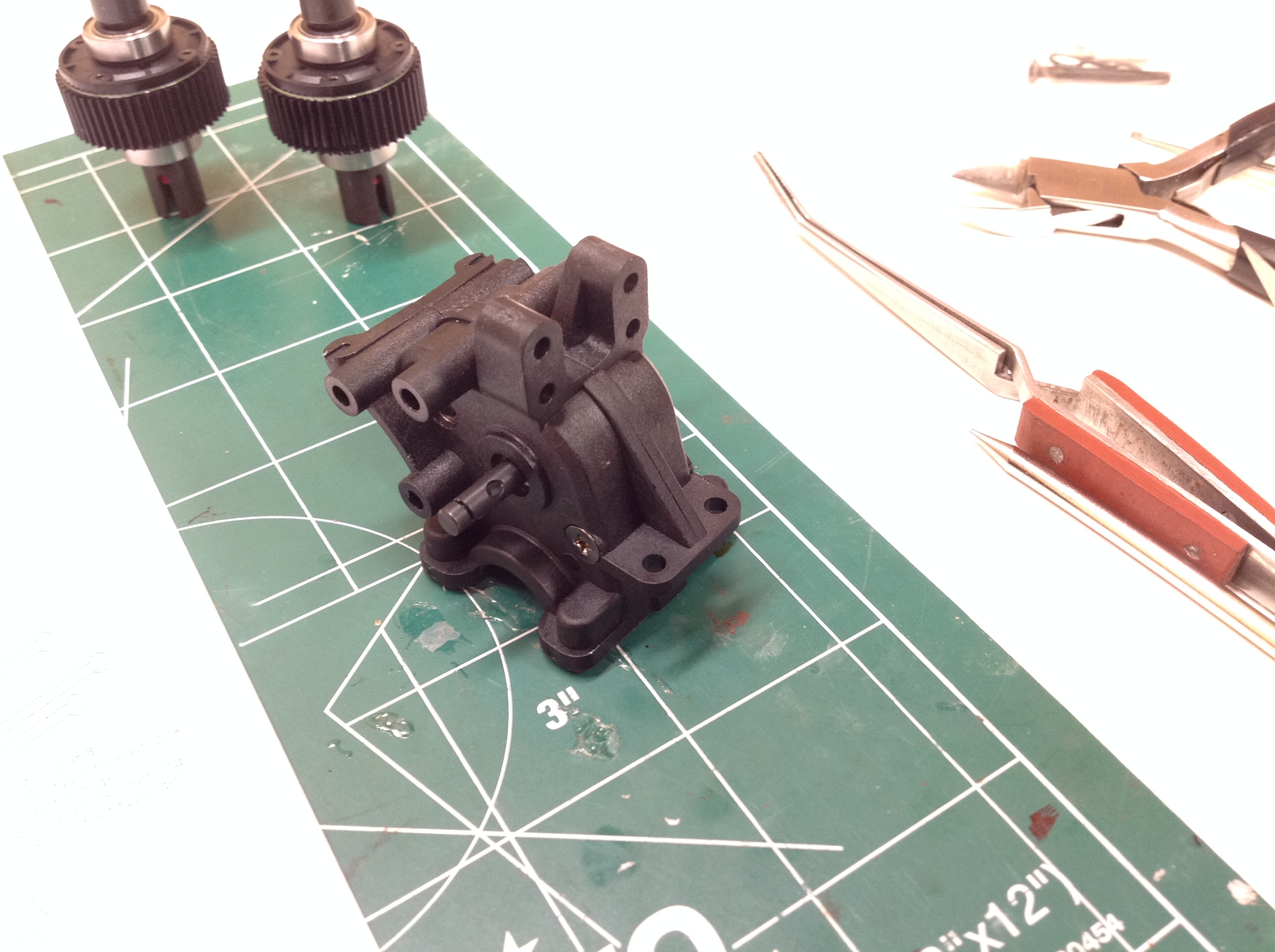
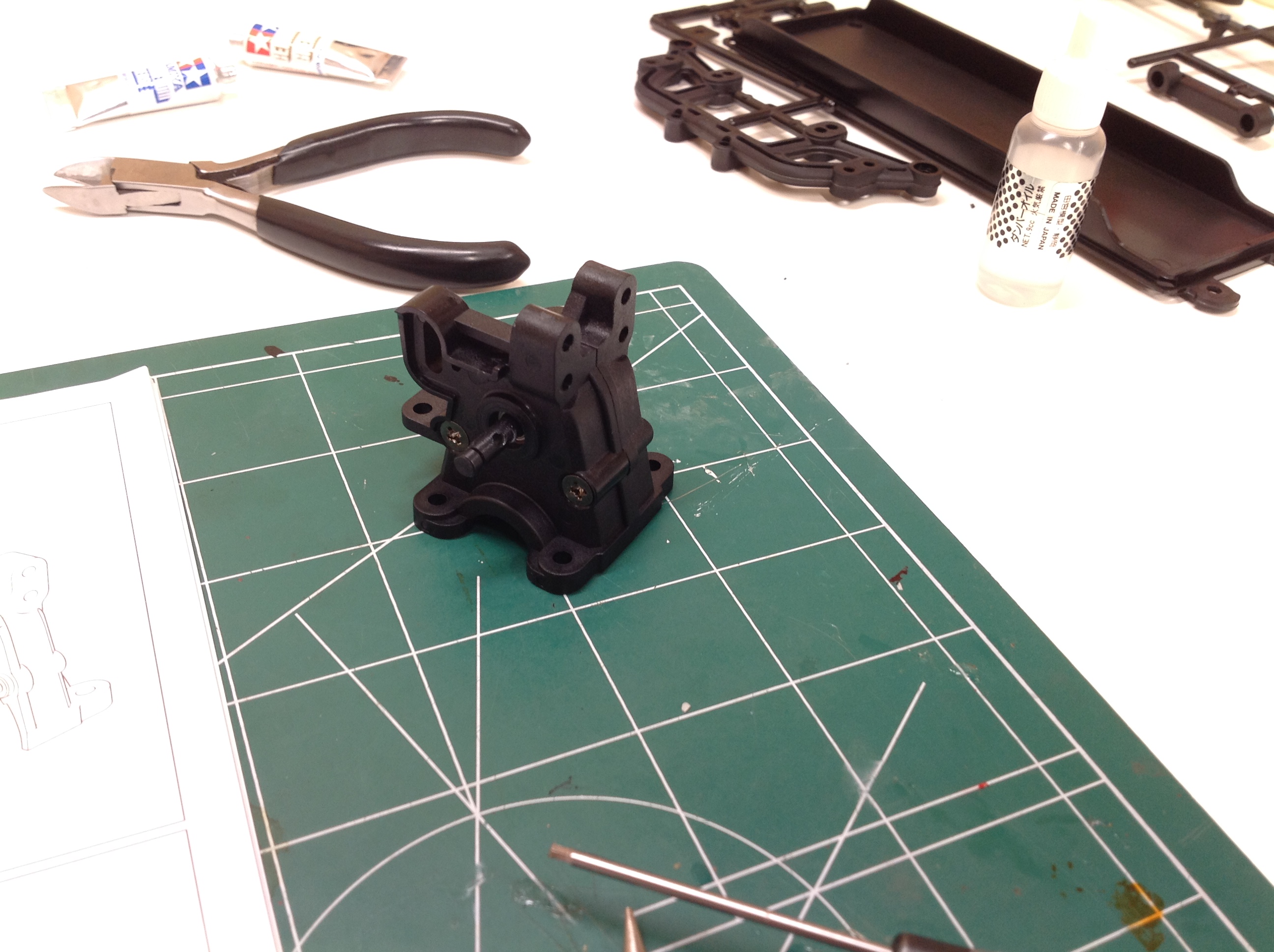
Here we see the front gearbox with the two gear shafts installed.
You can see the differential units in the background. The diff is
installed at the bottom side of the gearbox as shown on the right hand
image. The sprocket for the belt drive is also visible here.
This is a compact, sturdy unit.
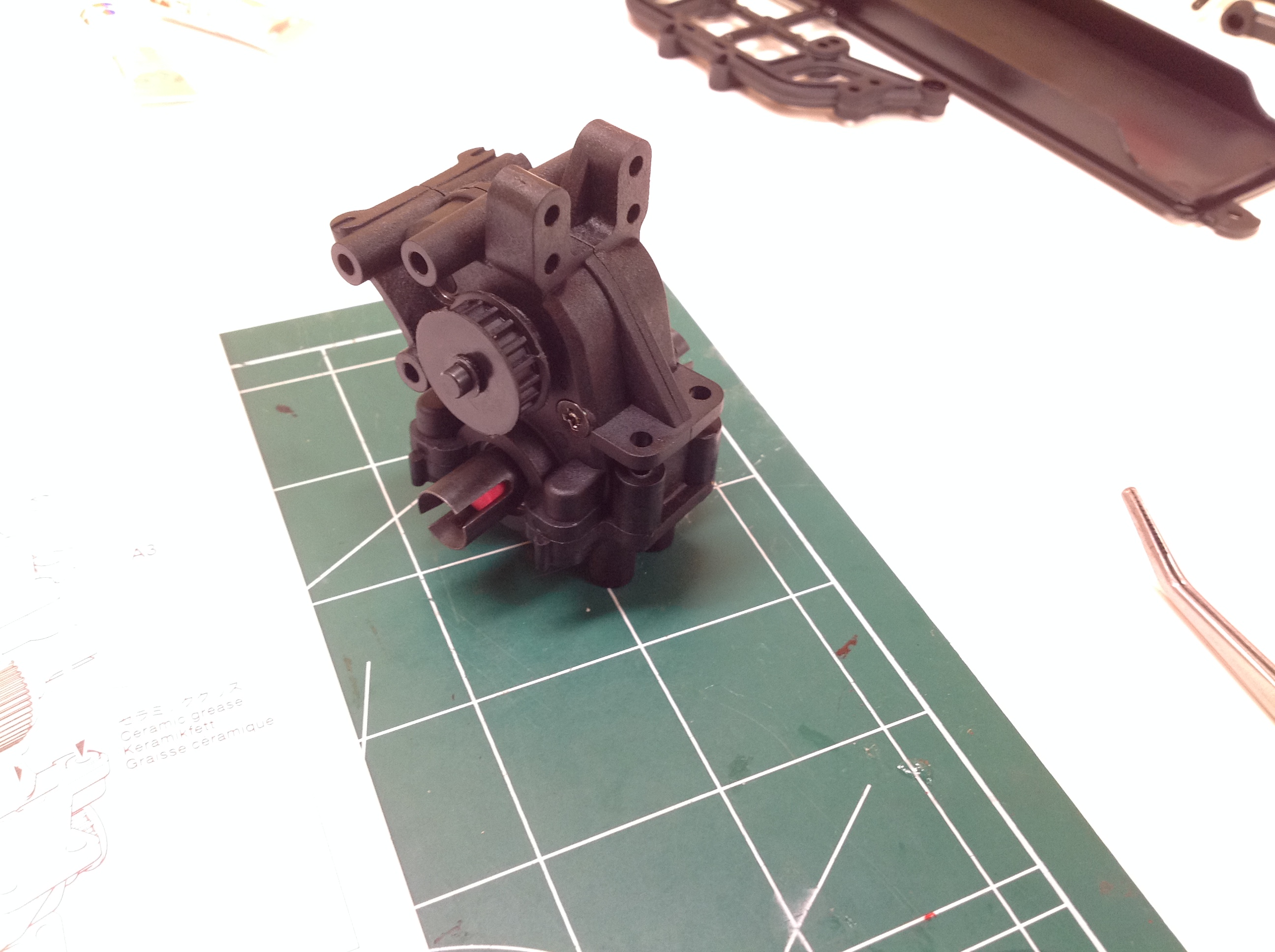
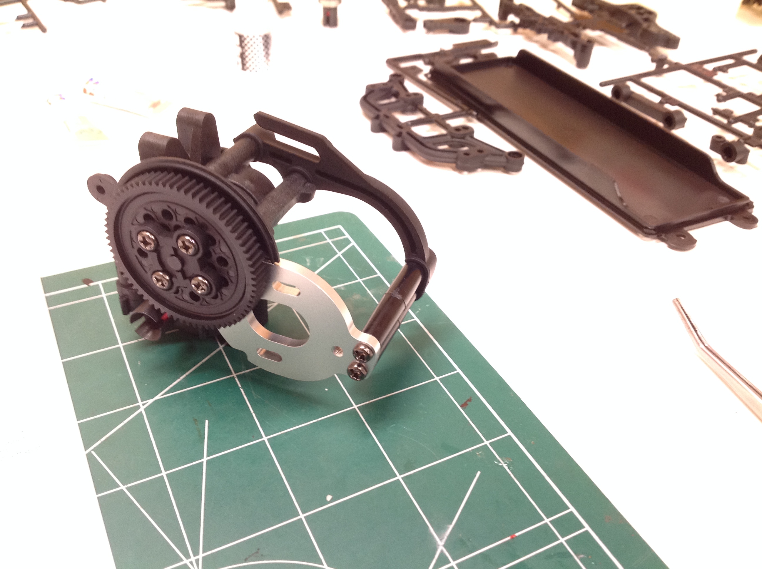
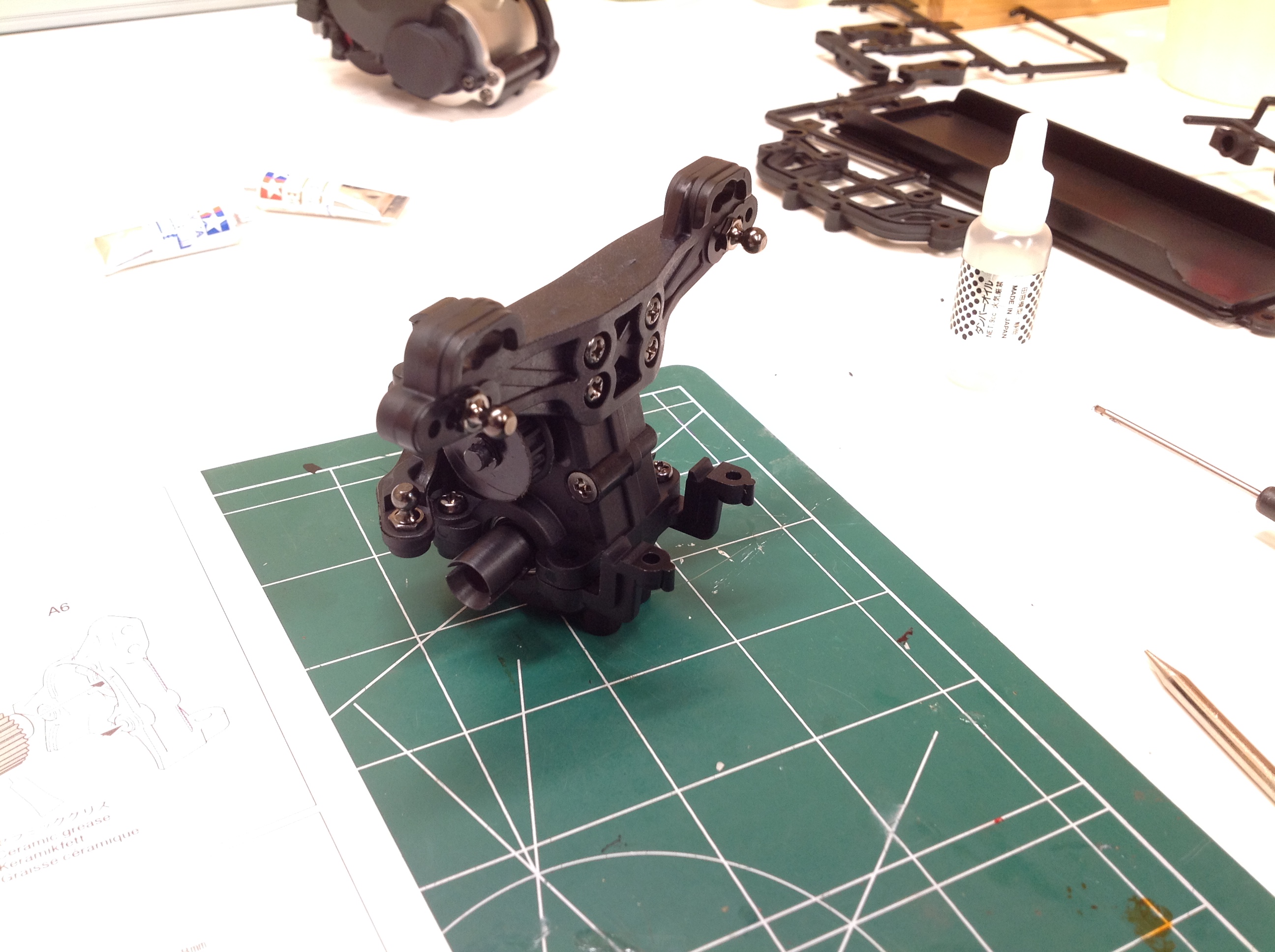
Now the aluminum motor mount and protective bracket are installed.
The gearbox is capable of supporting a slipper clutch, but instead a
solid spur gear is included in the kit as shown.
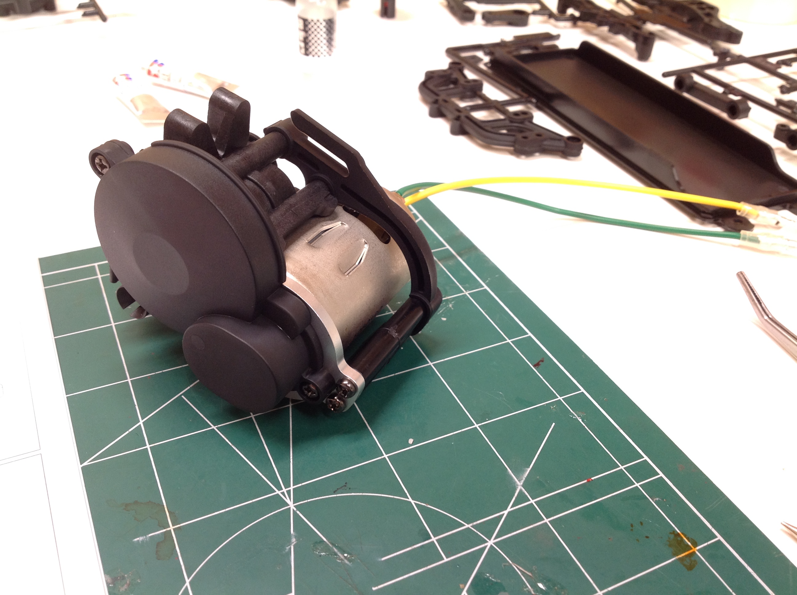
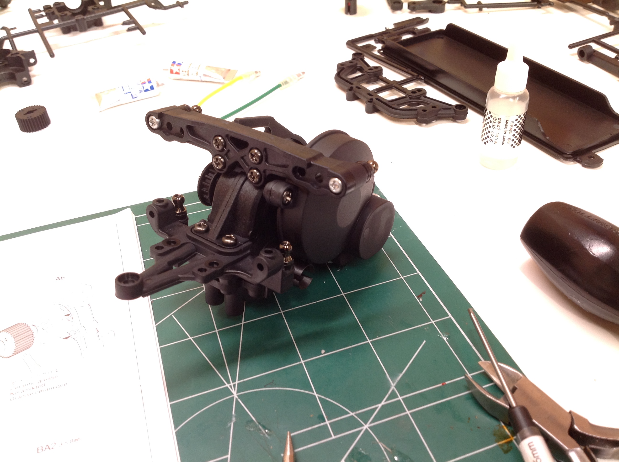
Once the silver can motor is installed, a plastic dust cover is applied
to protect the gear mesh. Then the shock tower and a front support
bracket are installed. The bracket forms the top support for the
double bellcrank steering.
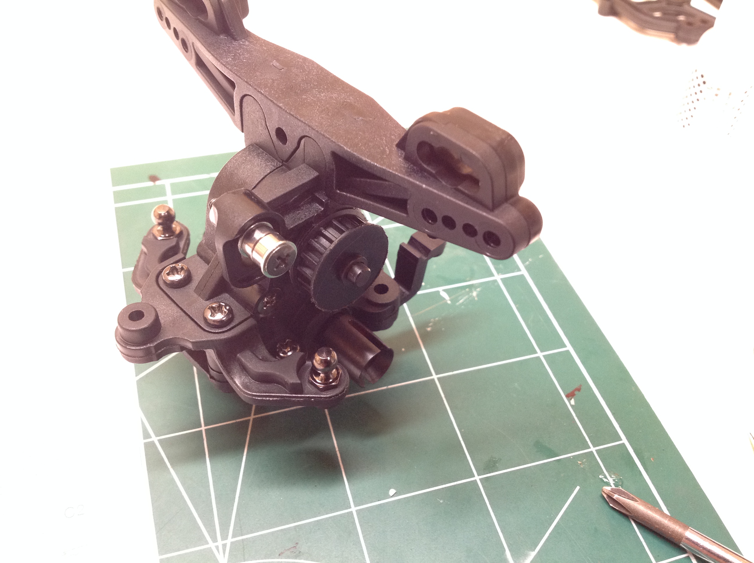
This may look familiar but it is actually the rear gearbox. It is
much like the front except that it does not contain the extra gear for
the motor. It includes a couple of support arms for an optional
sway bar.
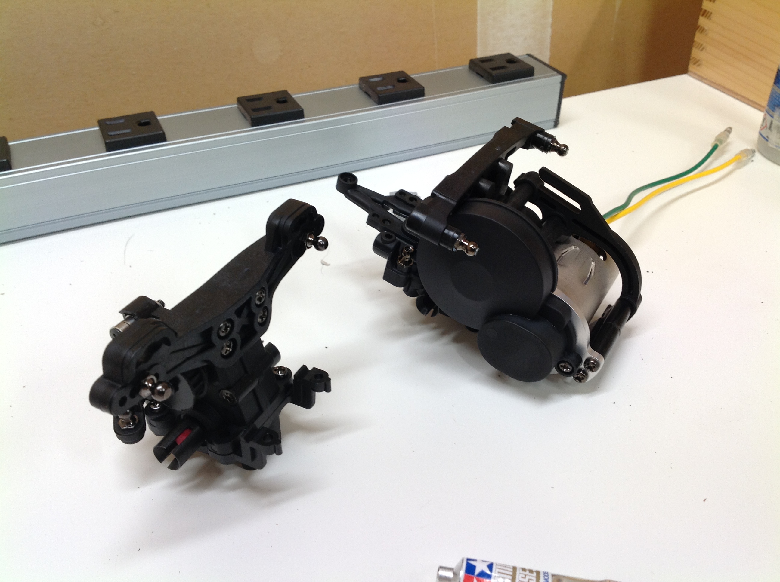
The bearing you can see attached to the rear gearbox is used as a
tensioner for the belt. When the belt is new you really don't need
it but you can slide it down to engage the belt as it wears. The
right hand image compares the completed front and rear gearboxes.
Normally you'd expect the one with the motor to be the rear, but that's
not the case here.
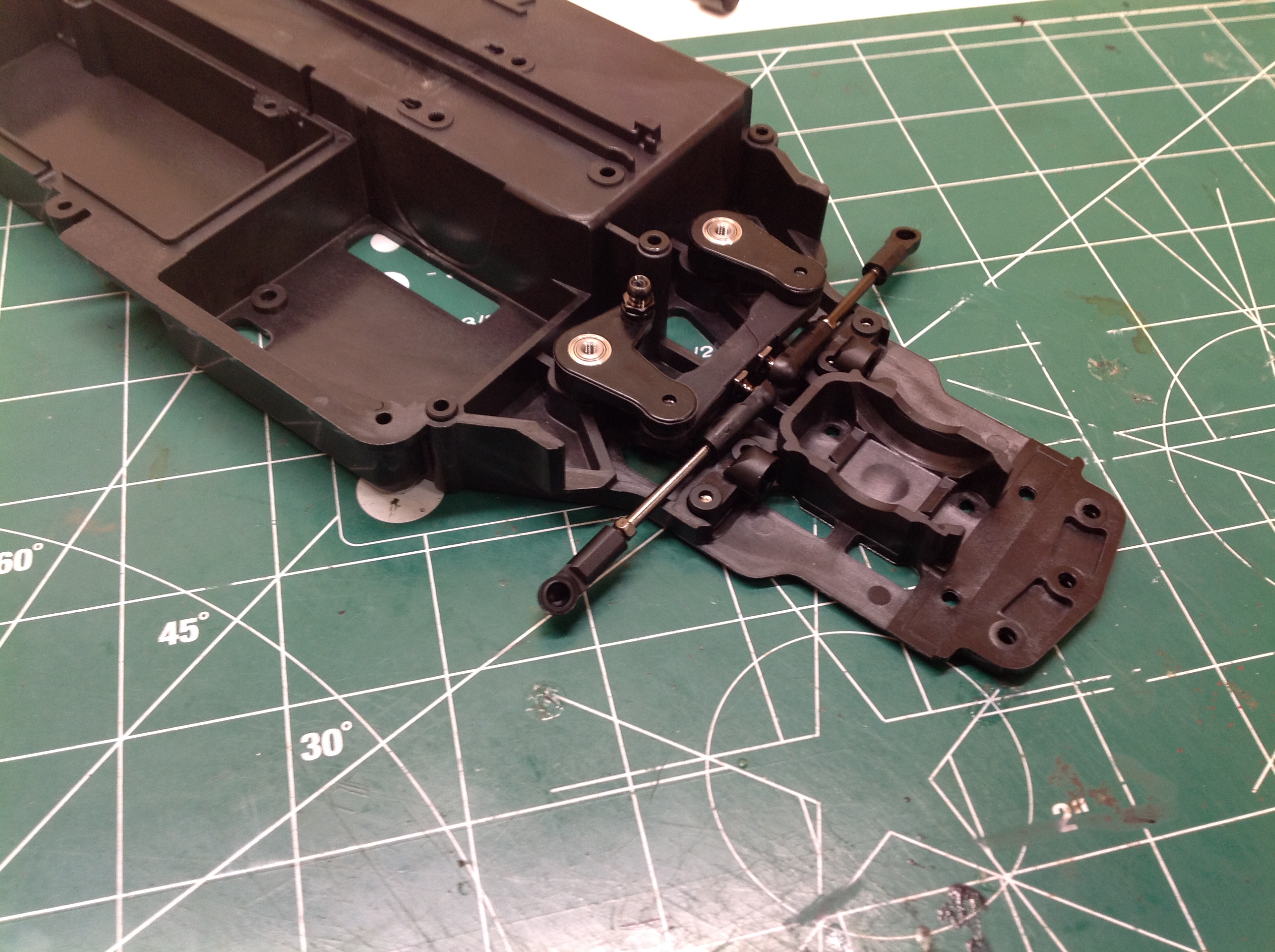
Here we see the double bellcrank steering being installed. The cranks ride on ball bearings supported by metal shafts.
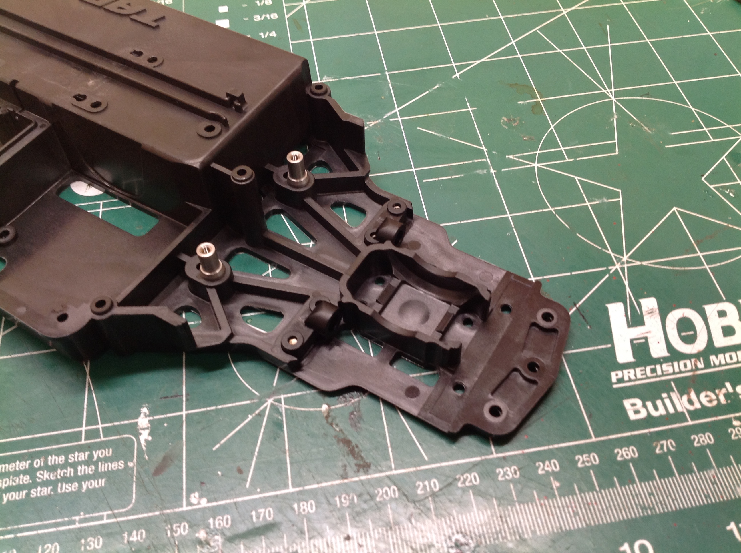
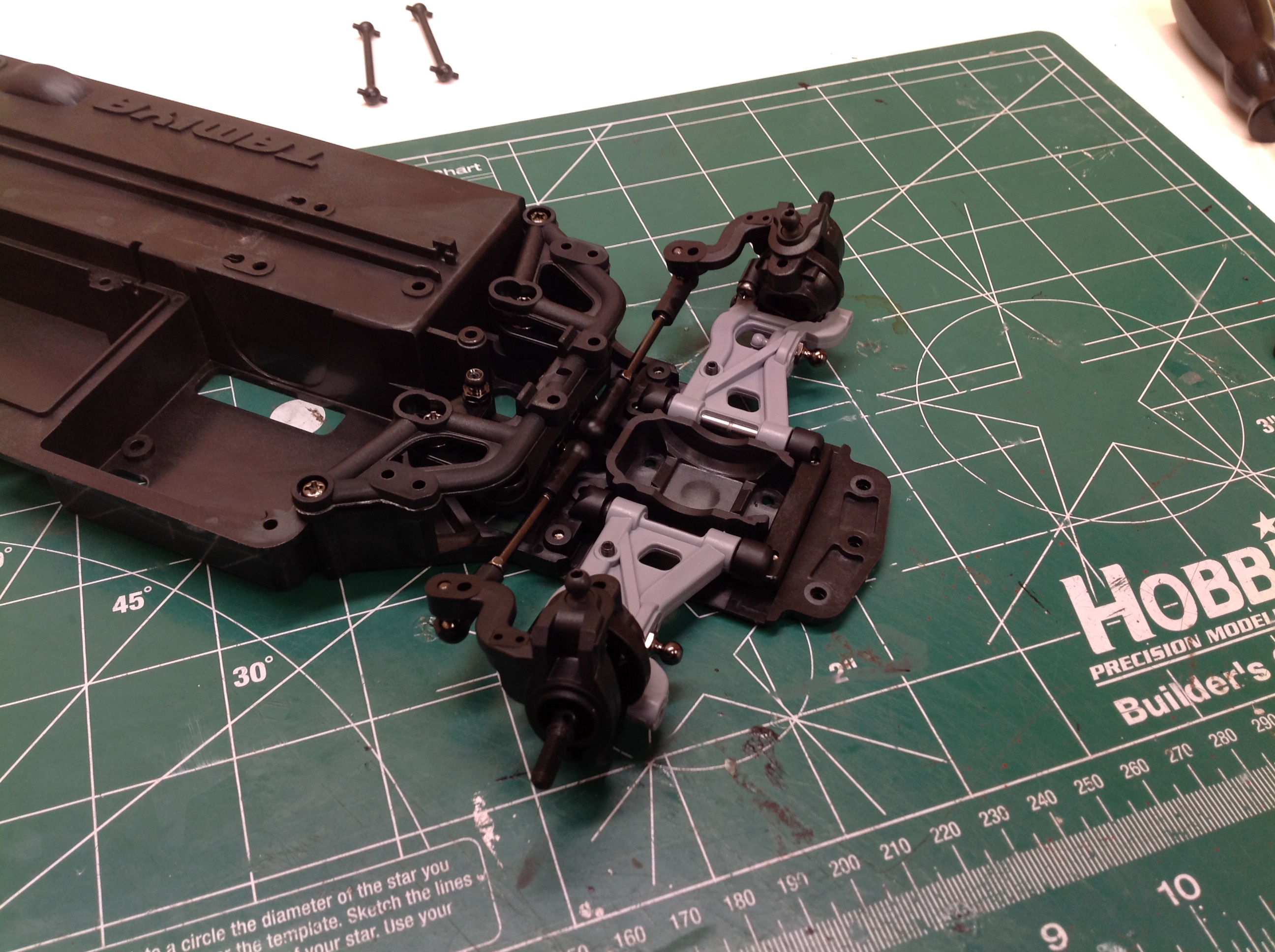
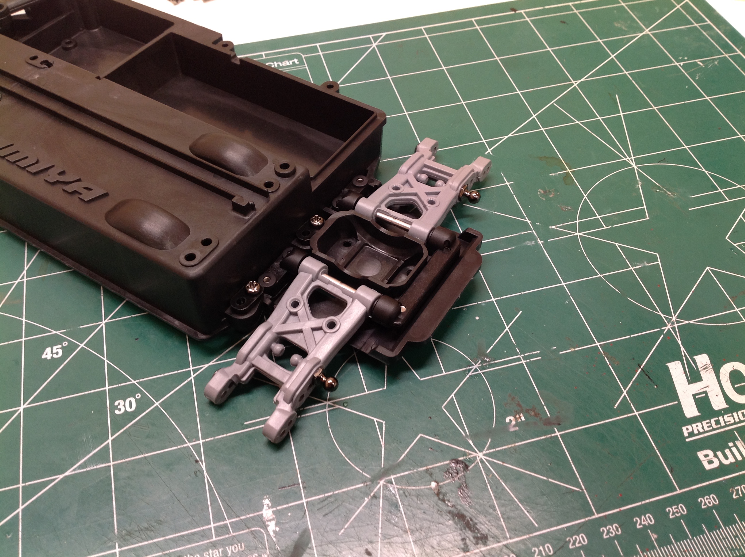
In many cases the suspension arms are attached directly to the gearbox
bulkhead, but in this case they attach to the chassis. The
brackets
which support the pivot axles are replaceable to get different toe
angles. The lower arms are made from a very flexible and resilient
plastic. The hubs seem to be fiber reinforced. The second
image shows the completed front suspension with the gearbox attached.
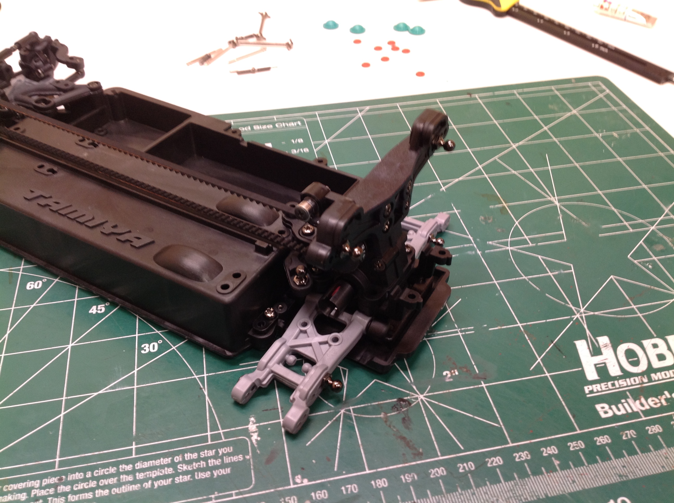
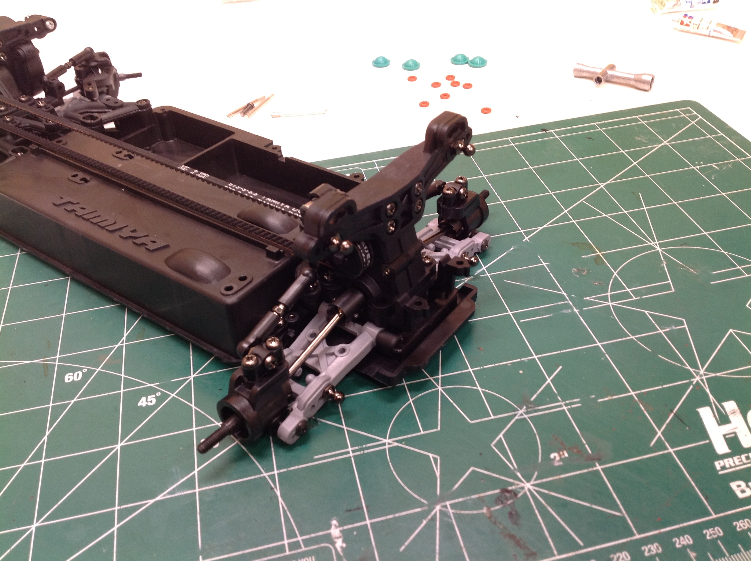
Here the rear suspension is being built which is much like the
front. The rear arms are reversible to give different shock mount
points. In the second image the rear gearbox has been attached and
the belt has been installed.
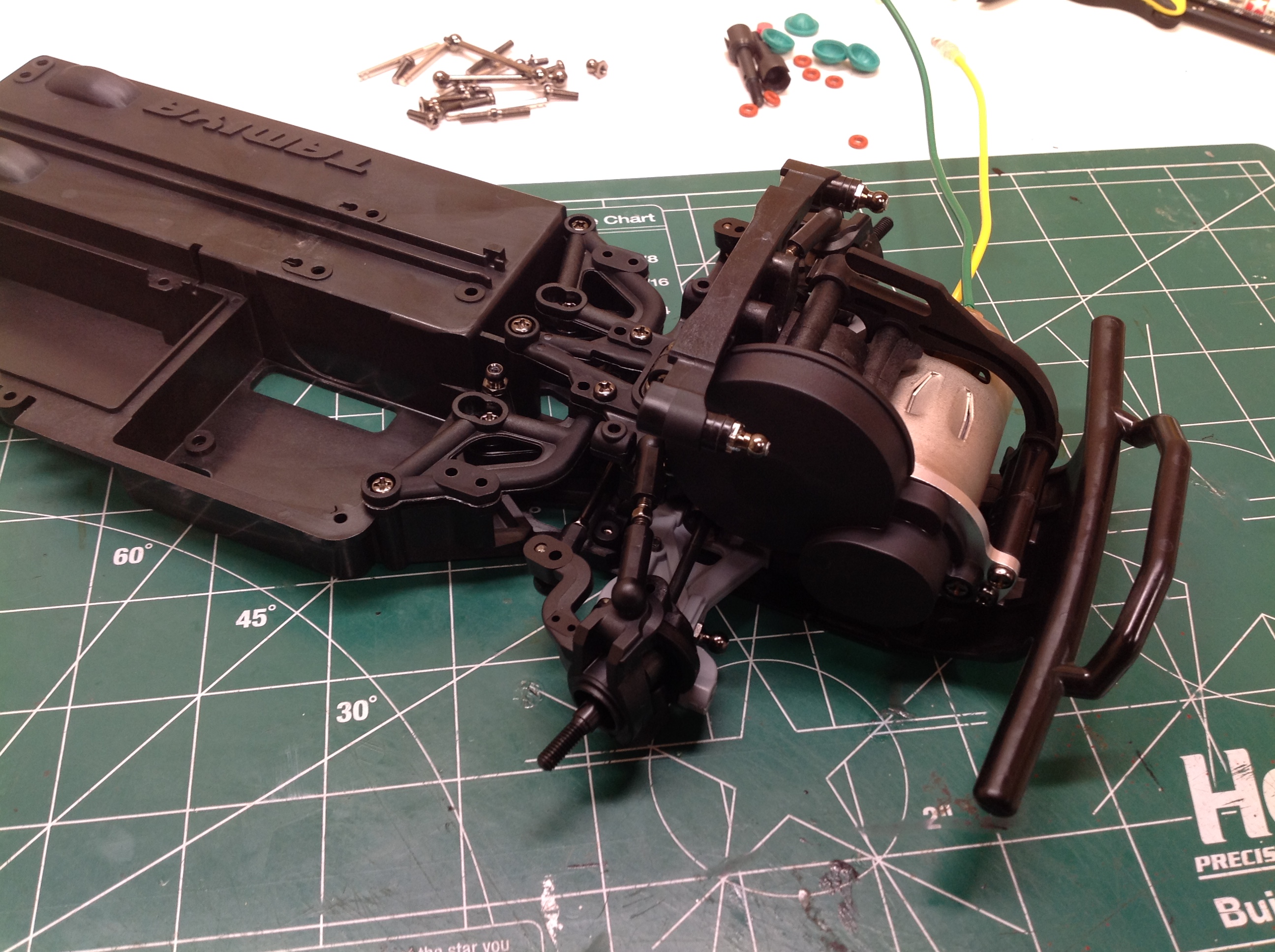
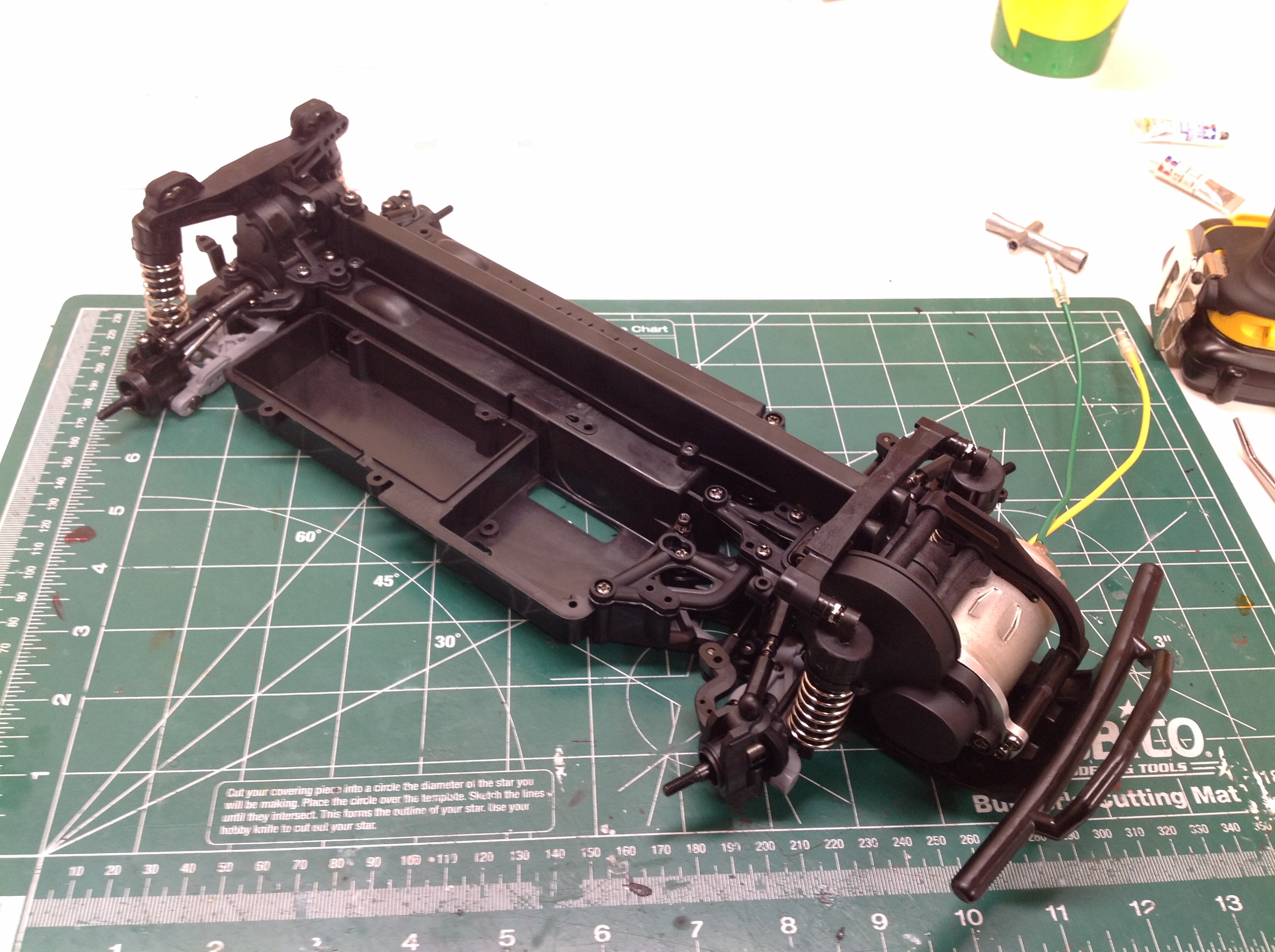
With the completion of the rear suspension the chassis is nearly
complete. At the right the CVA shocks are added and the guard has
been installed over the belt.
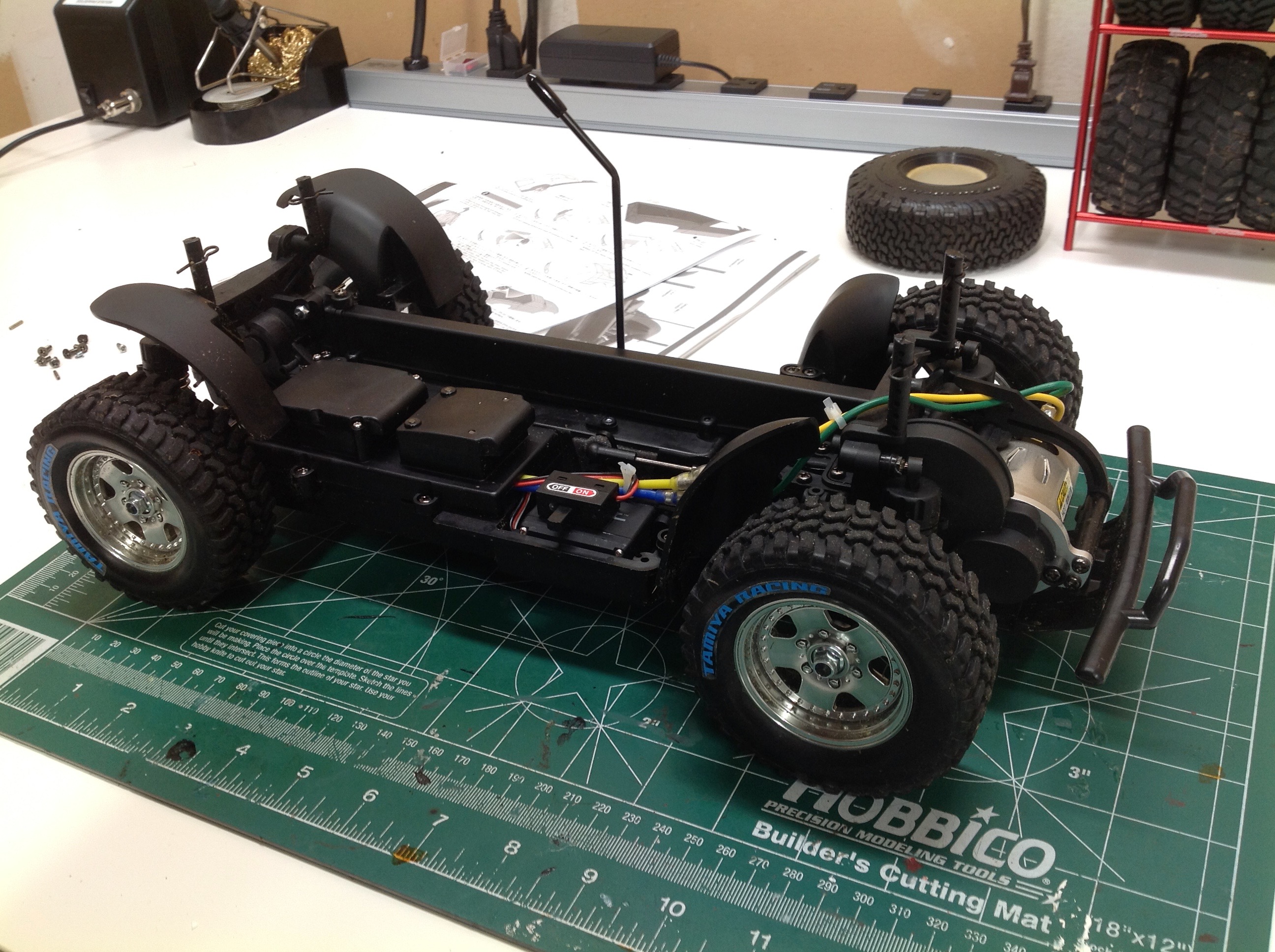
You can see here that all the electronics are hidden beneath a
shroud. The battery is installed from the bottom behind a screwed
hatch. The inner fenders don't completely seal the interior from
thrown debris, but they help.
©2018 Eric Albrecht