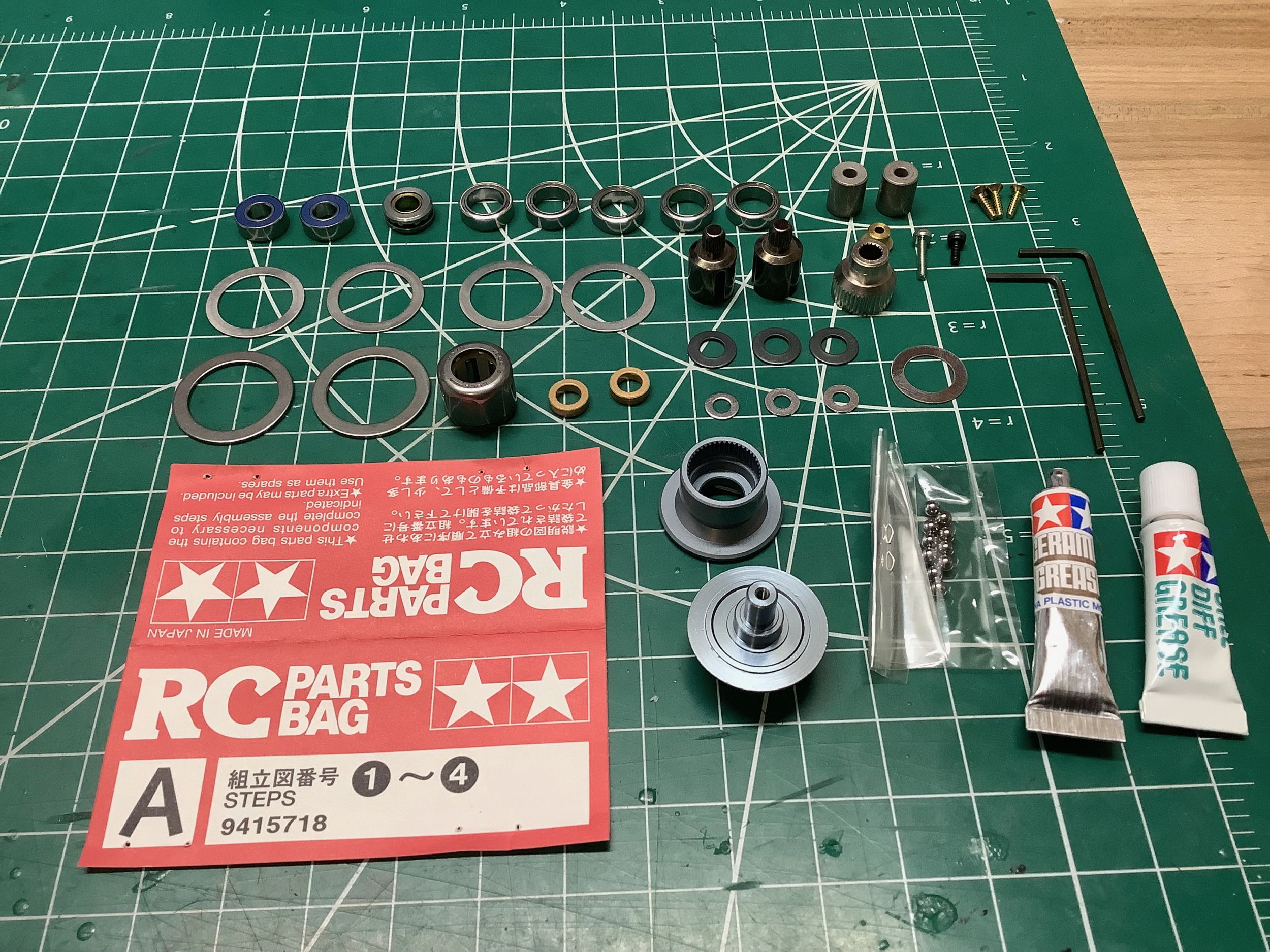
Hardware bag A contains the parts for Steps 1-4. Note the full
ball bearings. Step 1 begins with the rear ball differential which
uses 10ea 3mm steel balls housed in a plastic ring gear. I don't
intend to drive this model, but I packed the ball diff with grease
anyway to keep things smooth.
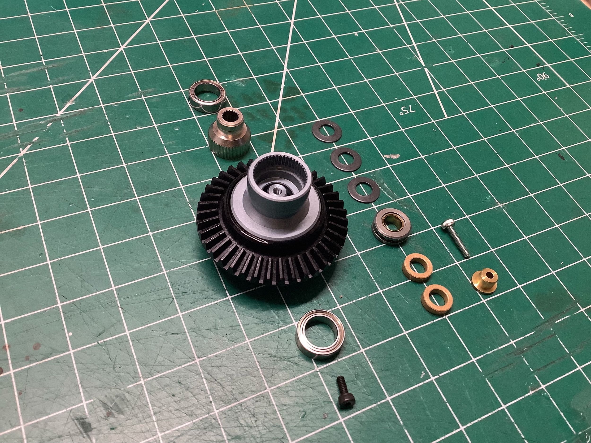
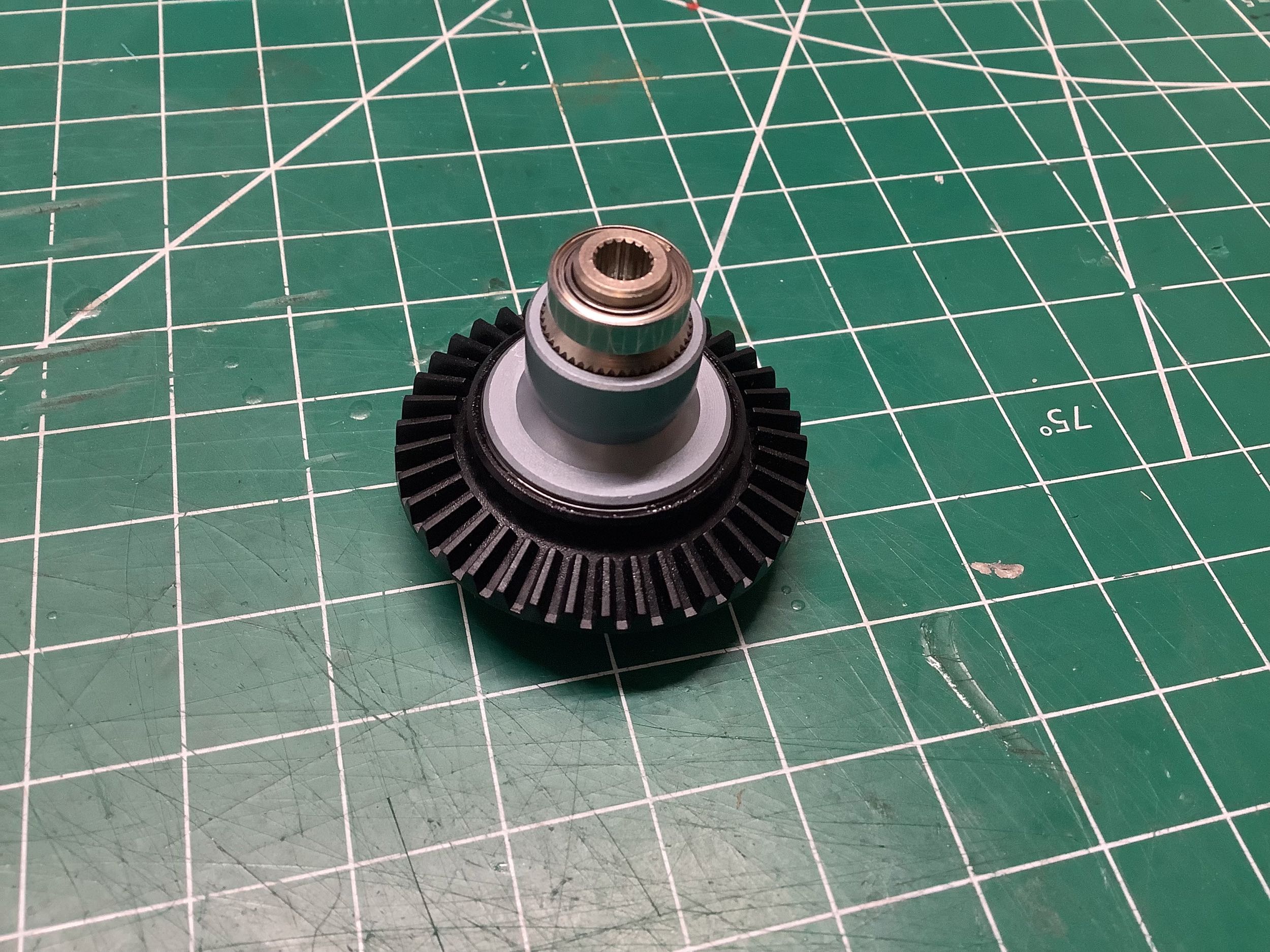
There are some unusual things about this ball differential. The
pressure plates are anodized aluminum with a slightly bluish hue.
The whole things spins on a pair of 12x8 ball bearings, but the ones
inside the spring stack are 8x5 bushings. This diff uses a stack
of 3 Belleville washers (disc springs) instead of coil spring. The
pressure plates are splined to accept the drive cups. Splines in
aluminum generally wouldn't last very long, so on the spring side there
is a "pressure plate cap" made of steel that adapts the larger spline
bore to a smaller size for the drive cups.
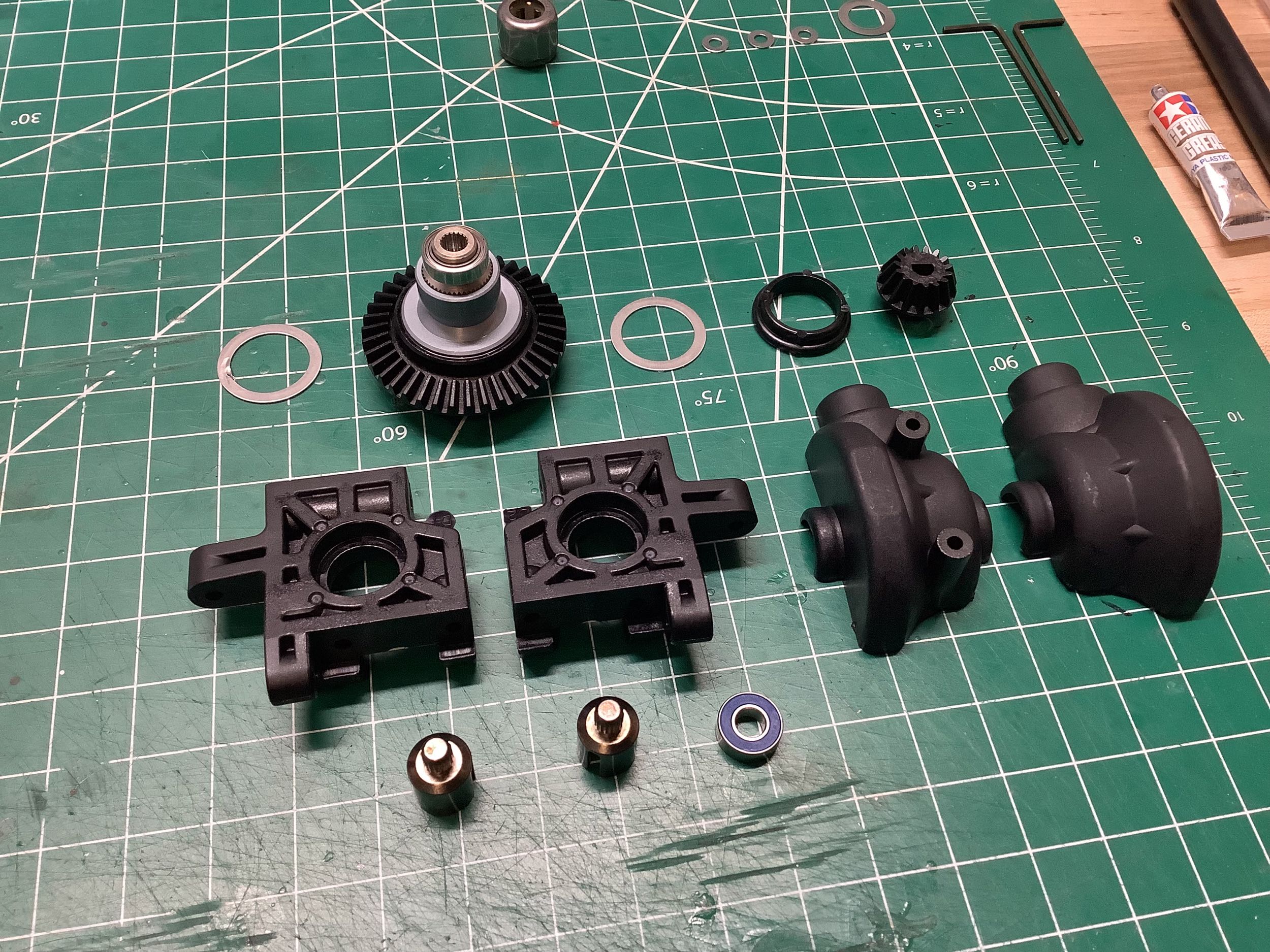
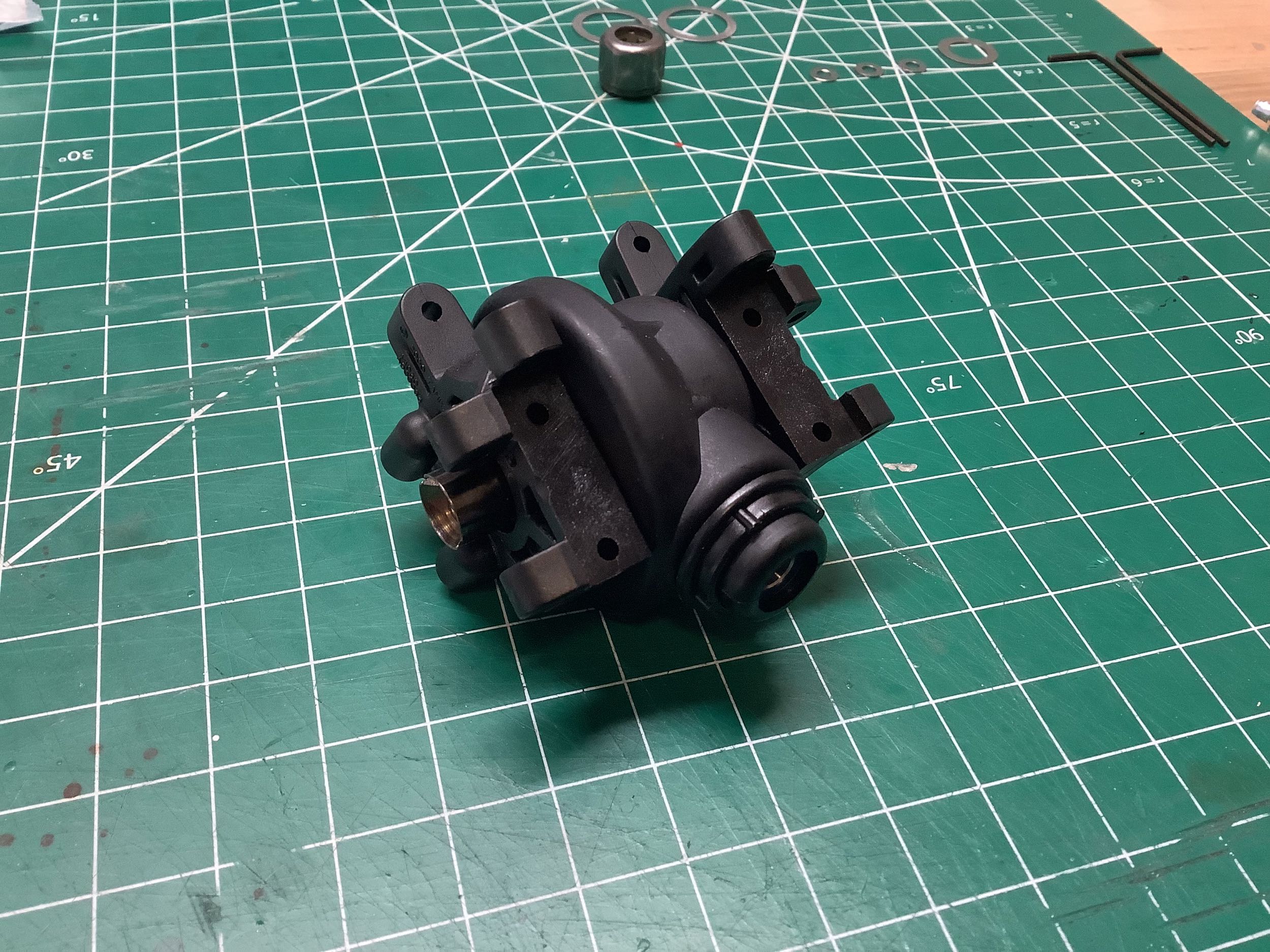
Now for Step 2. The ball differential sits inside an unusual assembly which consists
of a pair of housings which are then supported by a pair of
bulkheads. All of these parts are plastic. The diff housings
come from the TGR while the bulkheads are new for the Evo. The
diff housings are held together by a round collar at the pinion gear,
then the sides plug into the bulkheads. The drive cups can fall
out pretty easily, so the manual tells you to secure them in place with
the mysterious "synthetic rubber cement". In the USA, this is
generally understood to mean Shoe Goo. Something sticky which
doesn't fully cure is the idea. You don't want them to be glued
in, but you don't want them to fall out either. The designers were
smart enough to use metal shielded bearings inside the assembly for
minimum friction, and to use rubber shielded on the outside to keep out
contaminants.
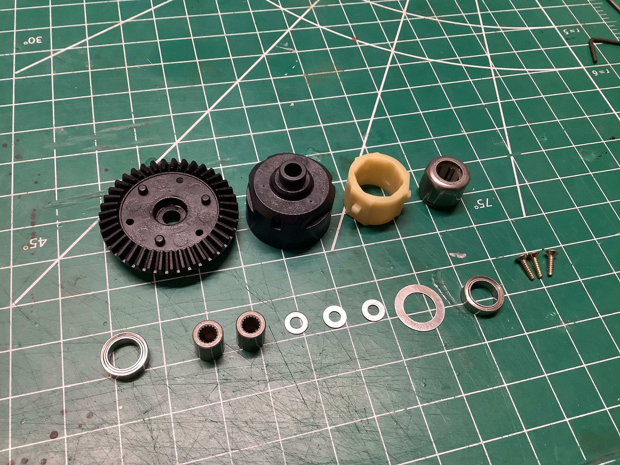
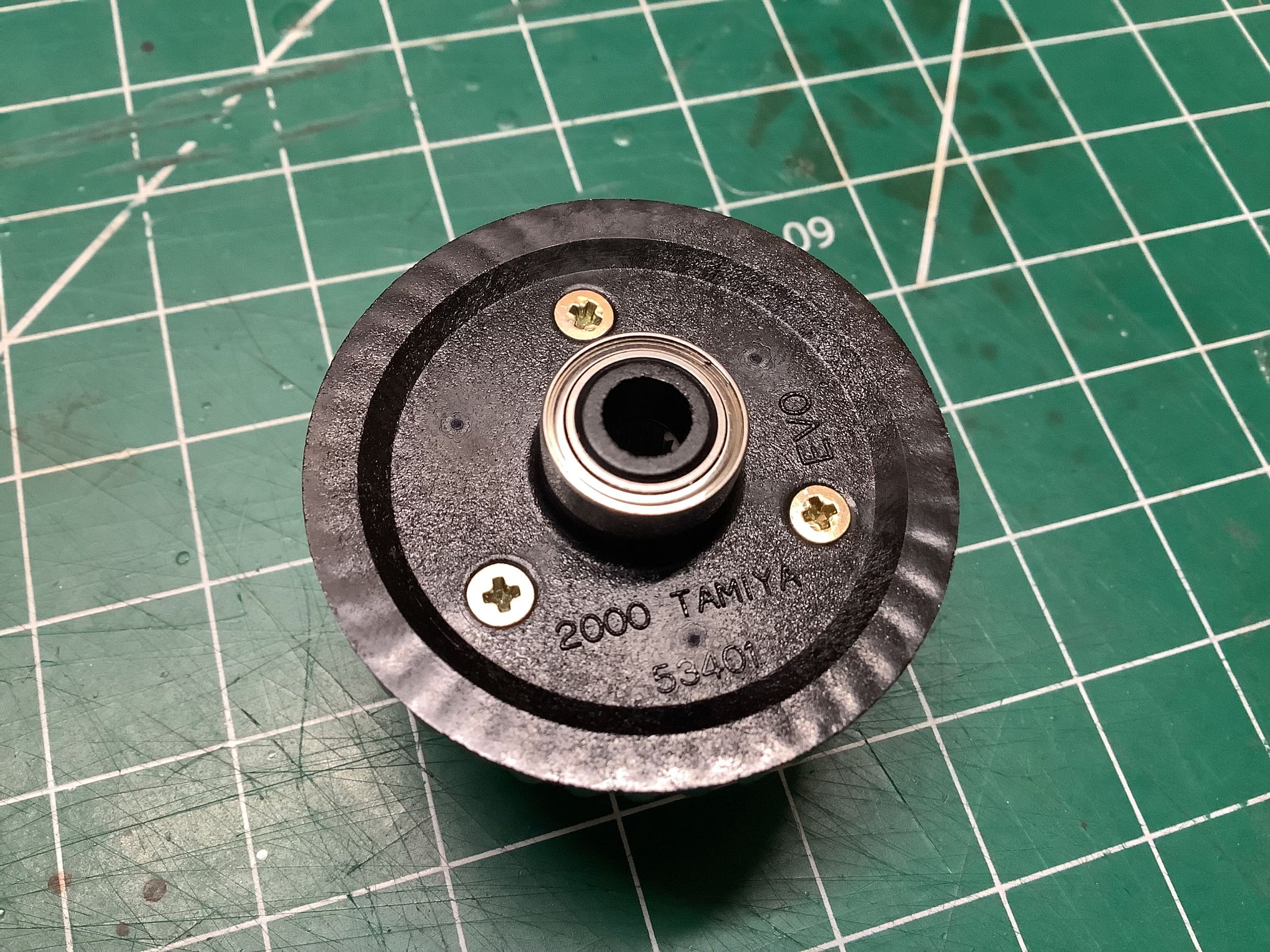
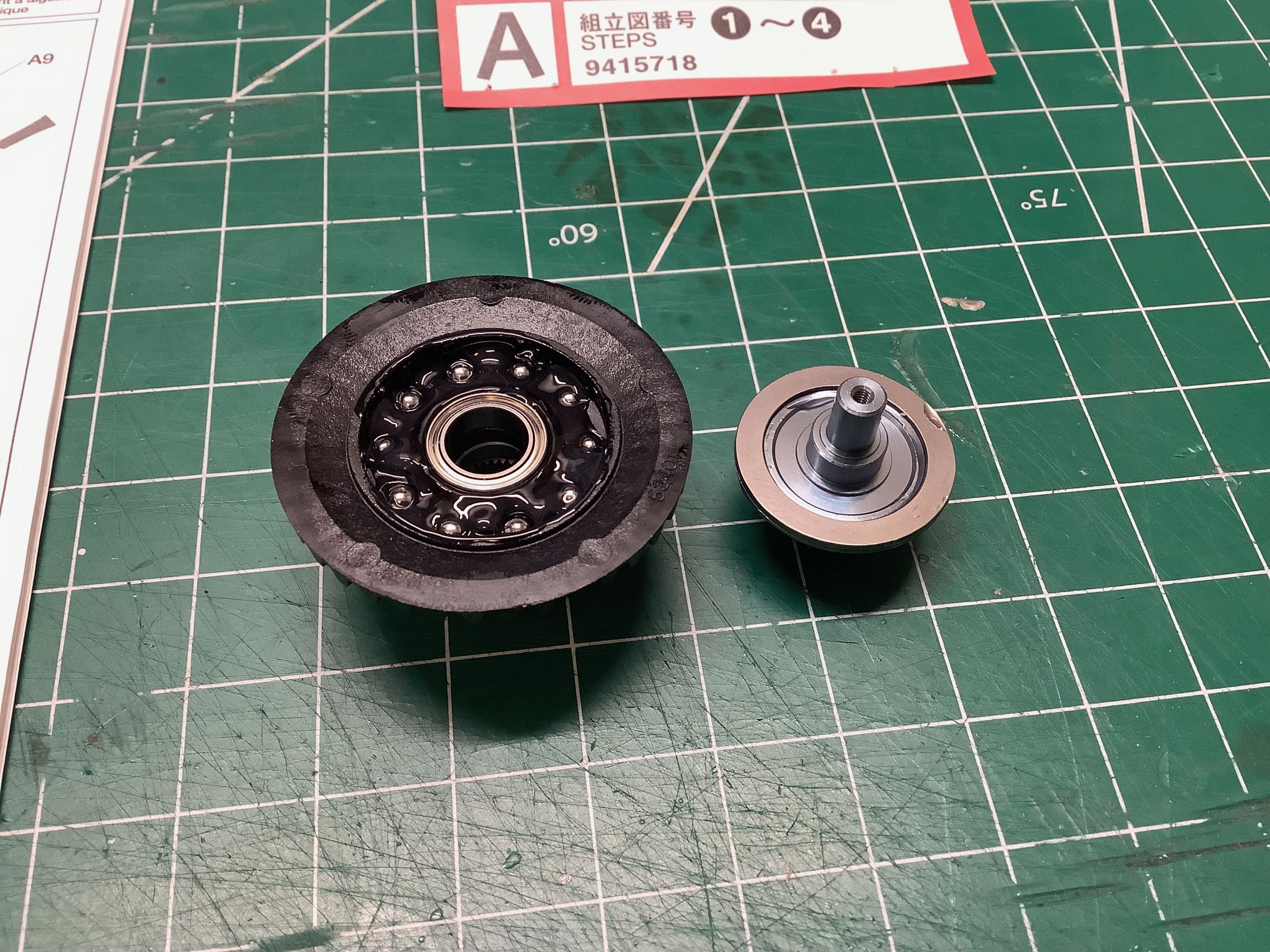
The front uses a one-way bearing instead of a ball
differential and is built in Step 3. There are two splined sleeves inside the bearing
which allow the left and right side to move independently mimicking
differential action. The ring gear is the same size as the one
used in the rear differential, and if you look at the picture on the
right you can see that the mold is stamped with "Evo" making this a
unique new part for this model. The "53401" identifies it as a part that
was also sold as an upgrade for the TB-01.
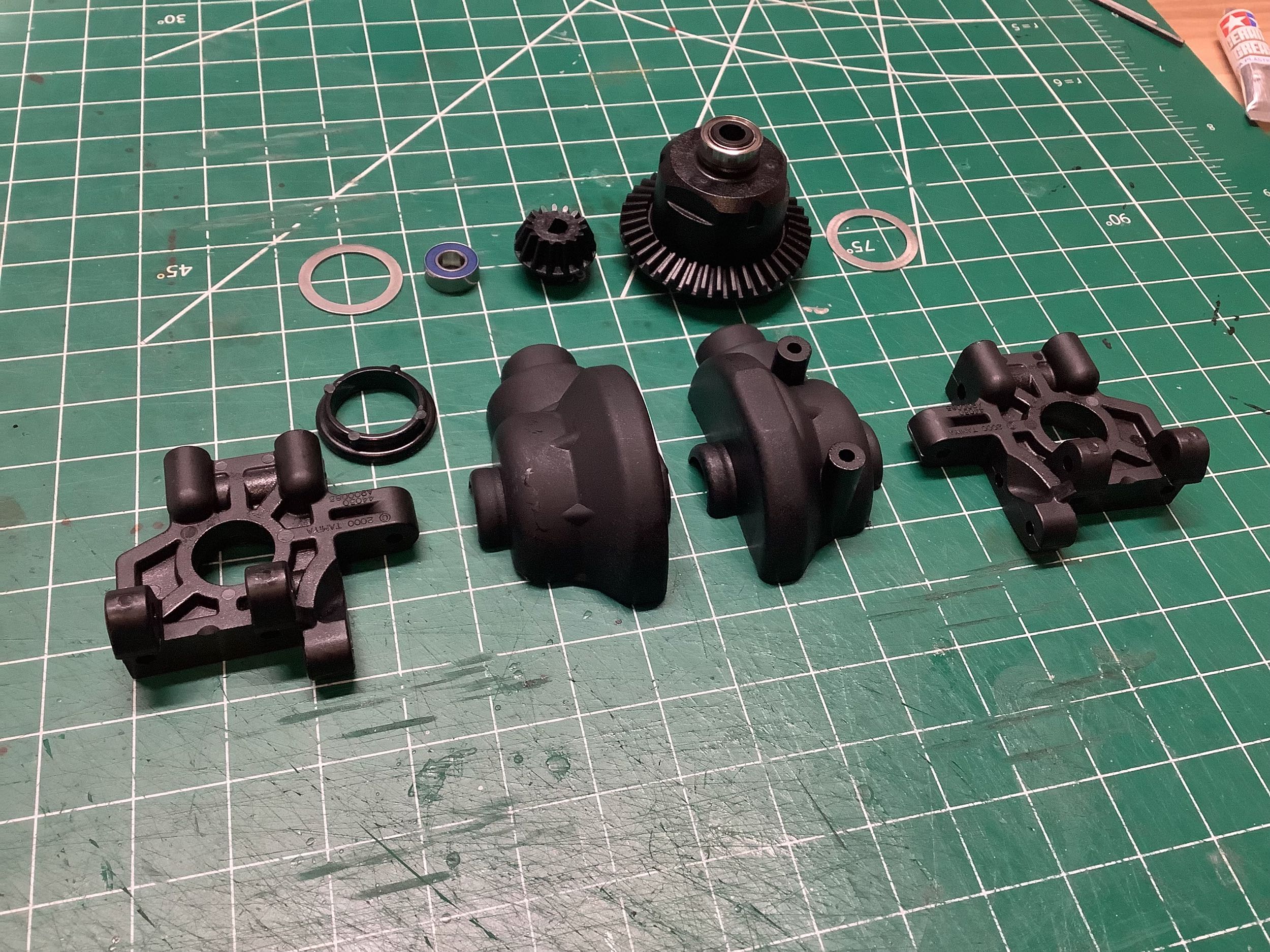
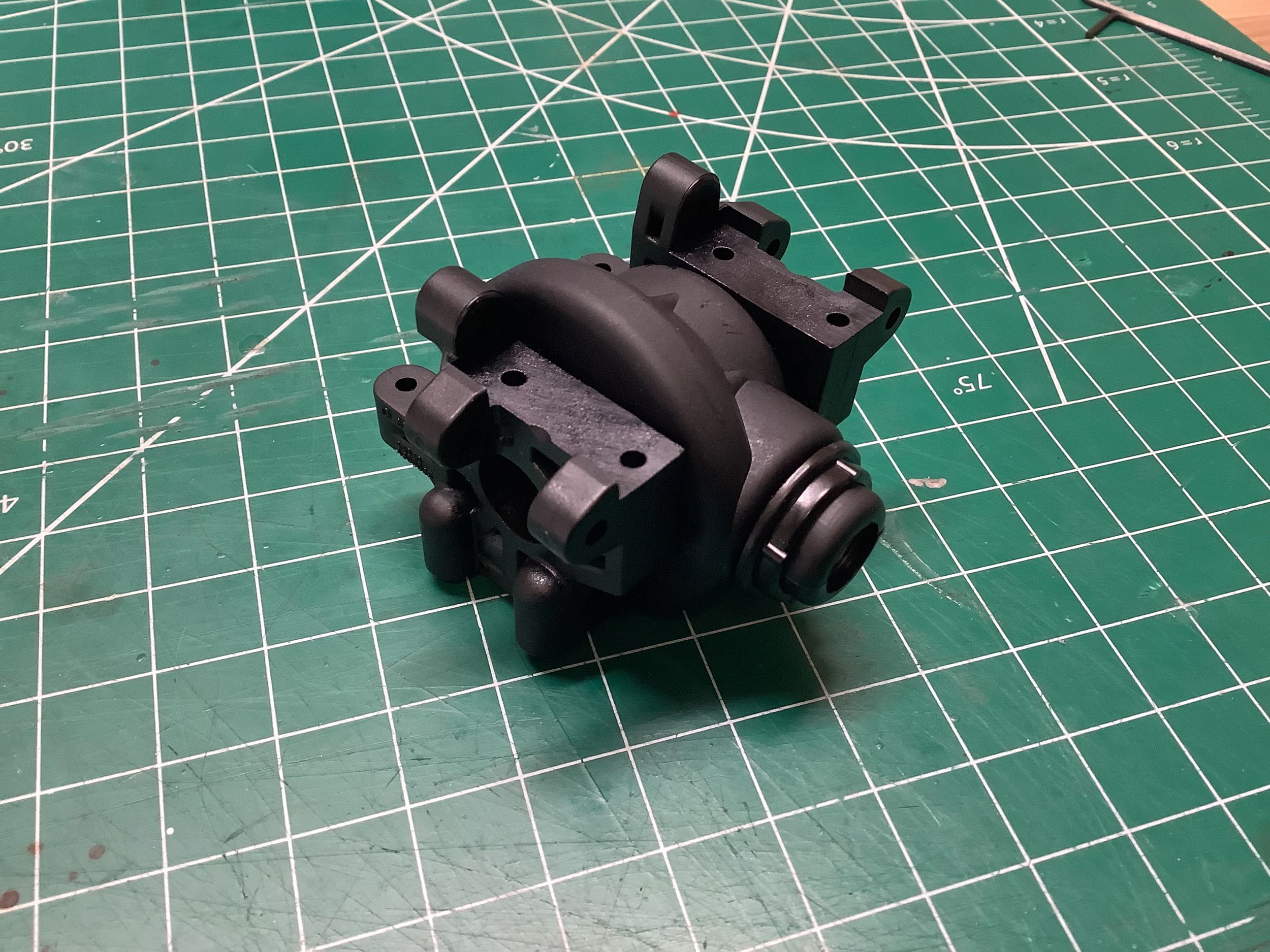
Step 4 builds the front assembly which uses exactly the same differential housing and
bulkhead parts that are used in the rear. Once assembled, you
can't tell the difference between this diff assembly and the one used
for the rear.
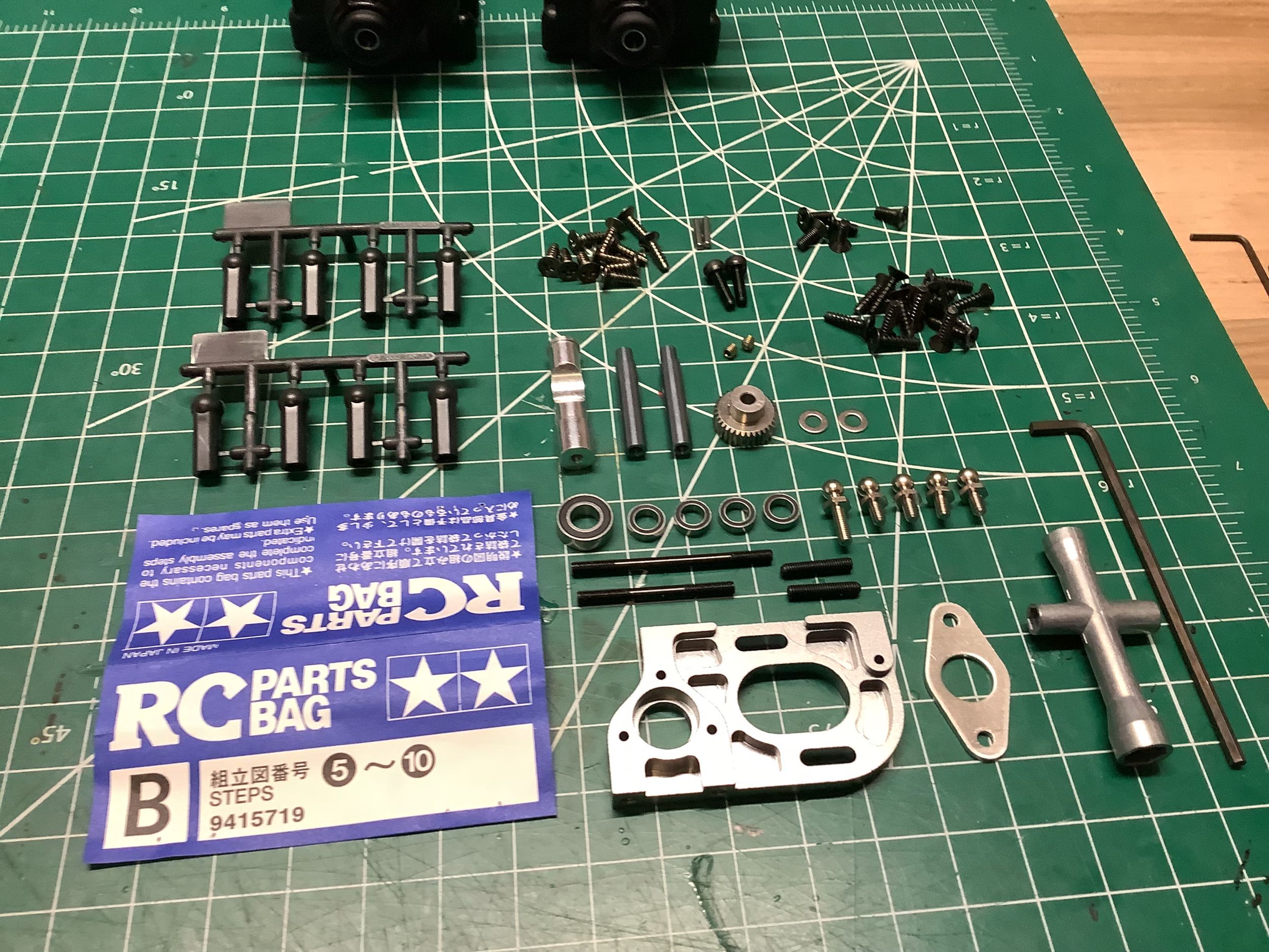
Hardware bag B contains the parts for Steps 5-10. These are the
parts to connect the previously built differentials to the
chassis. Note the lovely machined aluminum motor mount, and note
also that this model precedes the ubiquitous Tamiya blue.
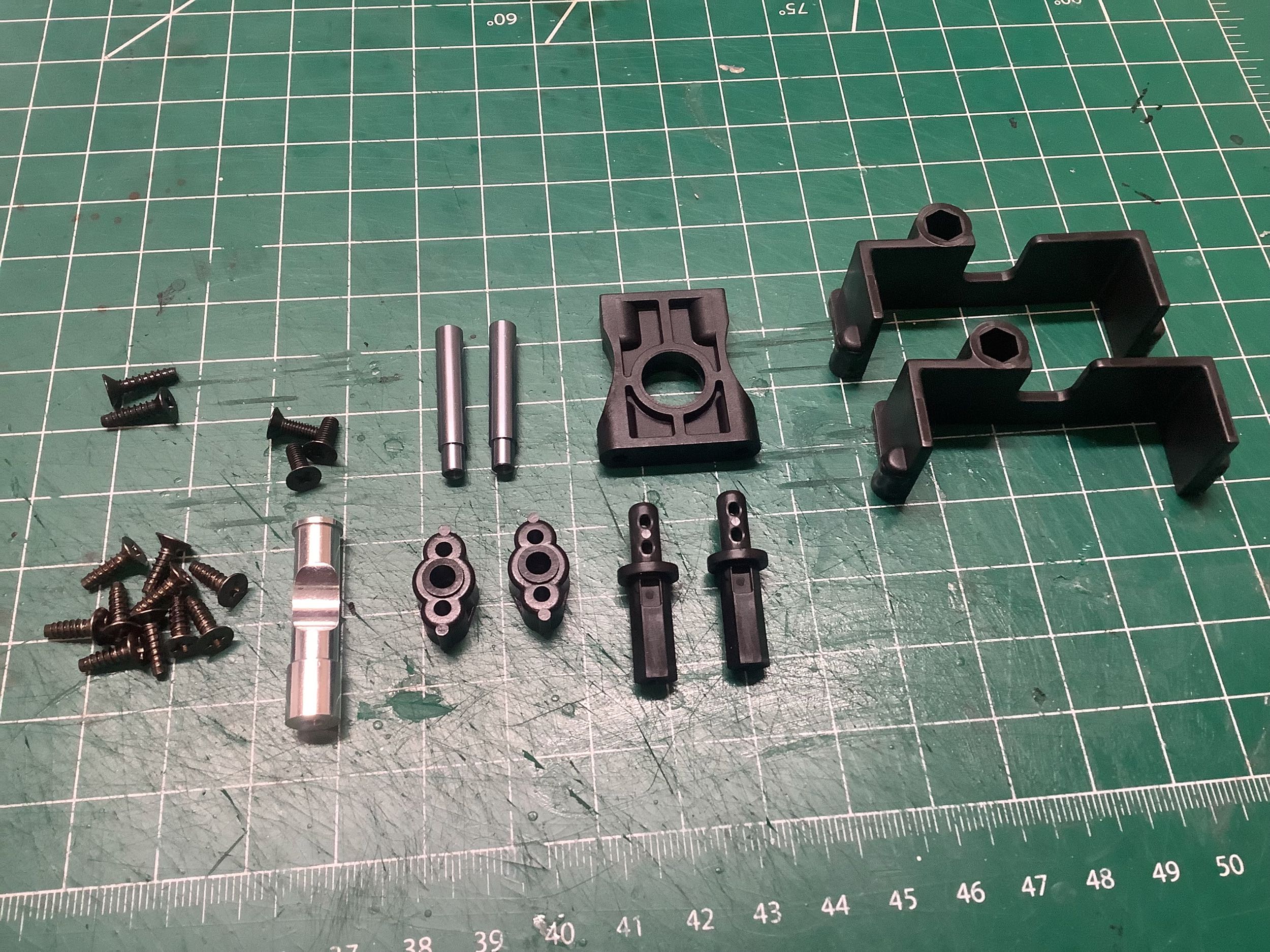
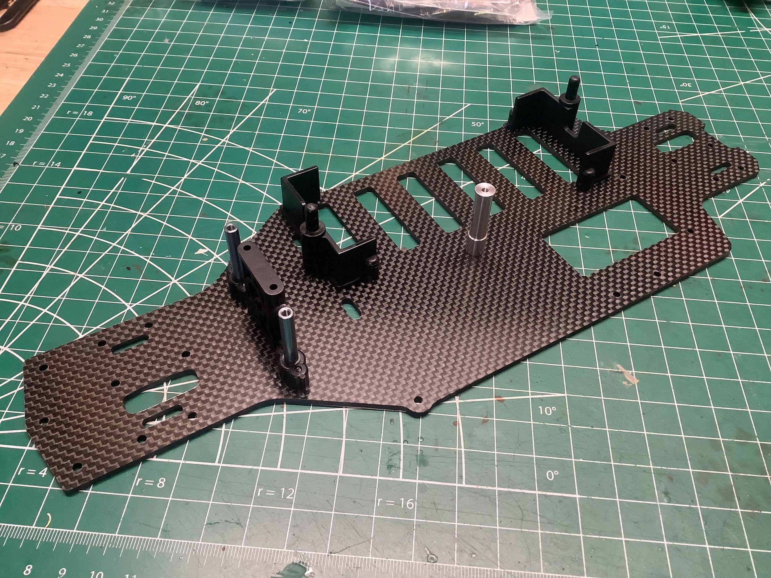
Here are the parts for Step 5 which include the battery supports and a
center bulkhead. These are attached to the 2.5mm thick carbon
chassis plate as shown. The metal posts on either side of the
center bulkhead are for the steering cranks. Unlike many TRF
models which use only hex machine screws, this model still uses plenty
of JIS self tapping screws as shown. Only the parts threading into
metal are machine screws.
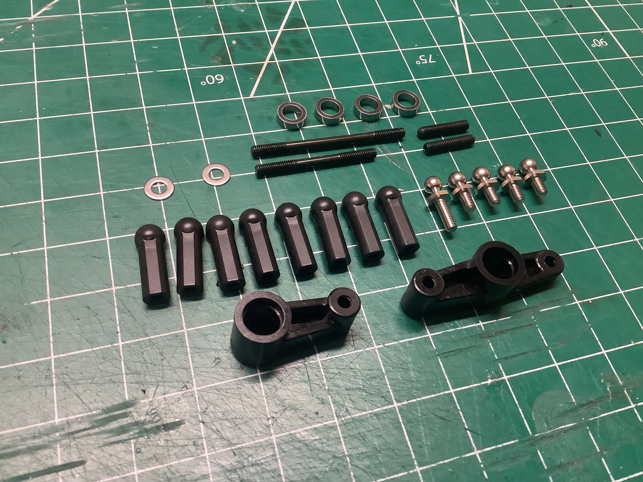
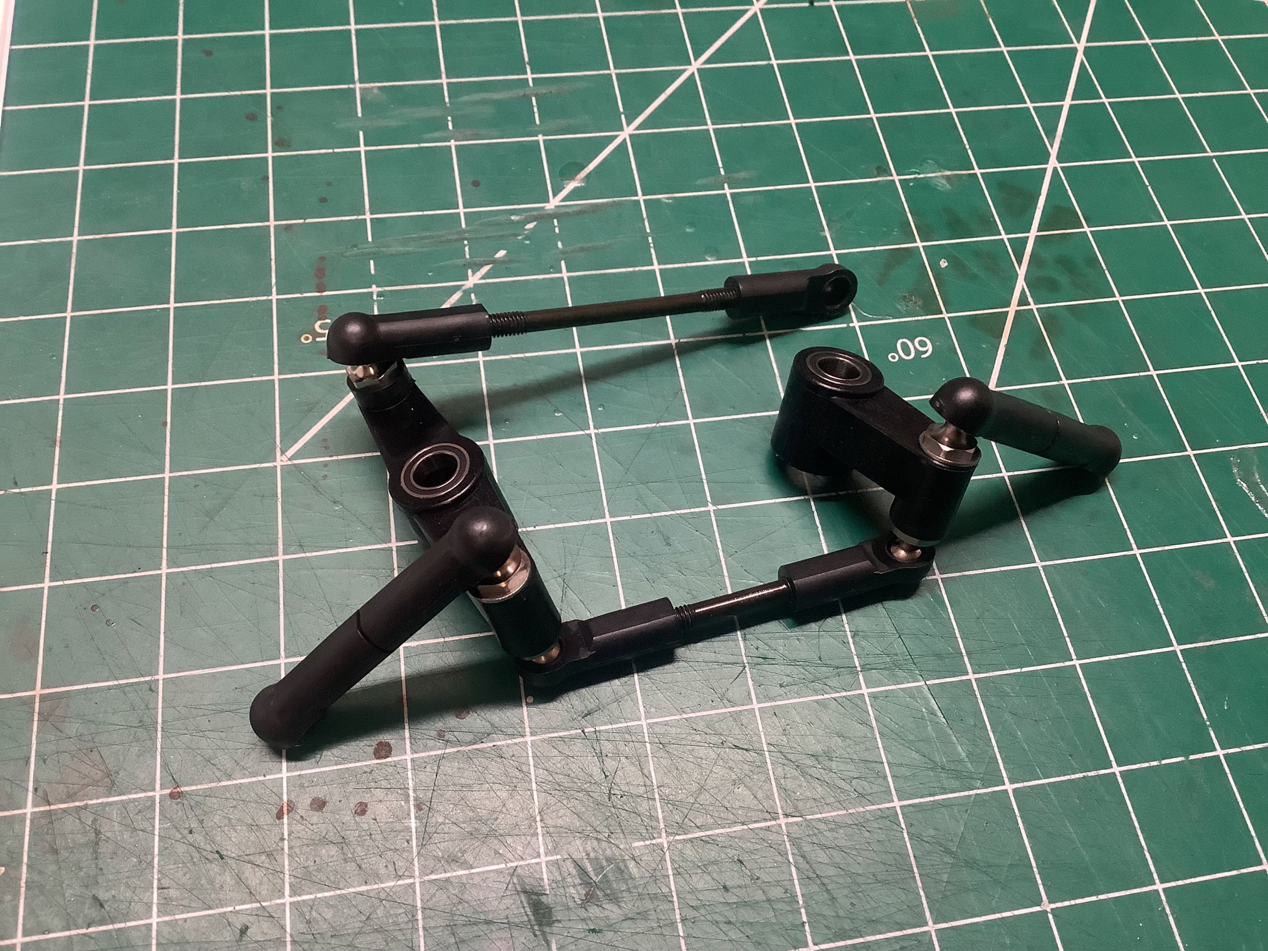
Next the tie rods are built for the steering assembly in Step
6. These are just threaded rods, not turnbuckles. The dual
bell cranks ride on ball bearings.
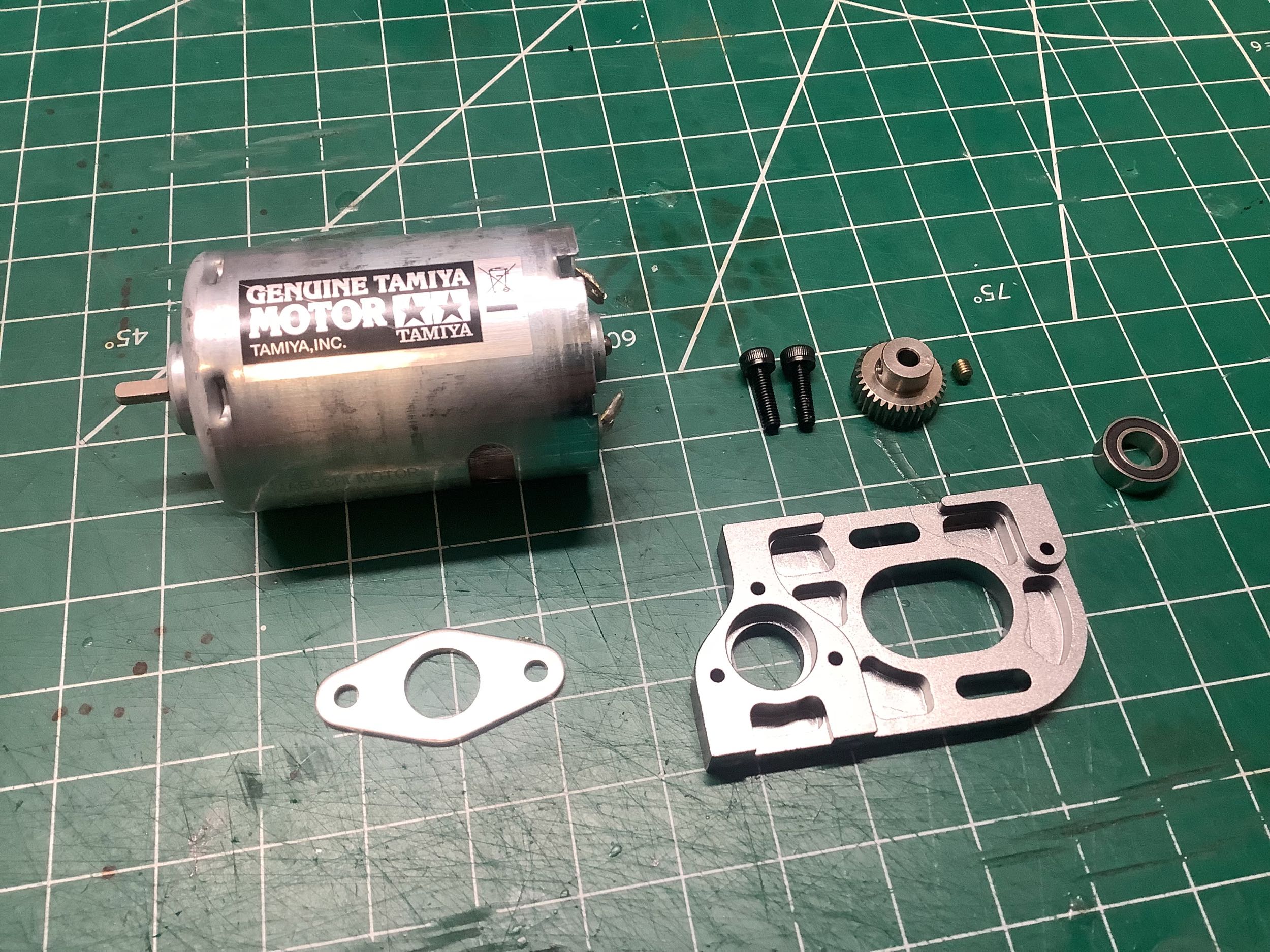
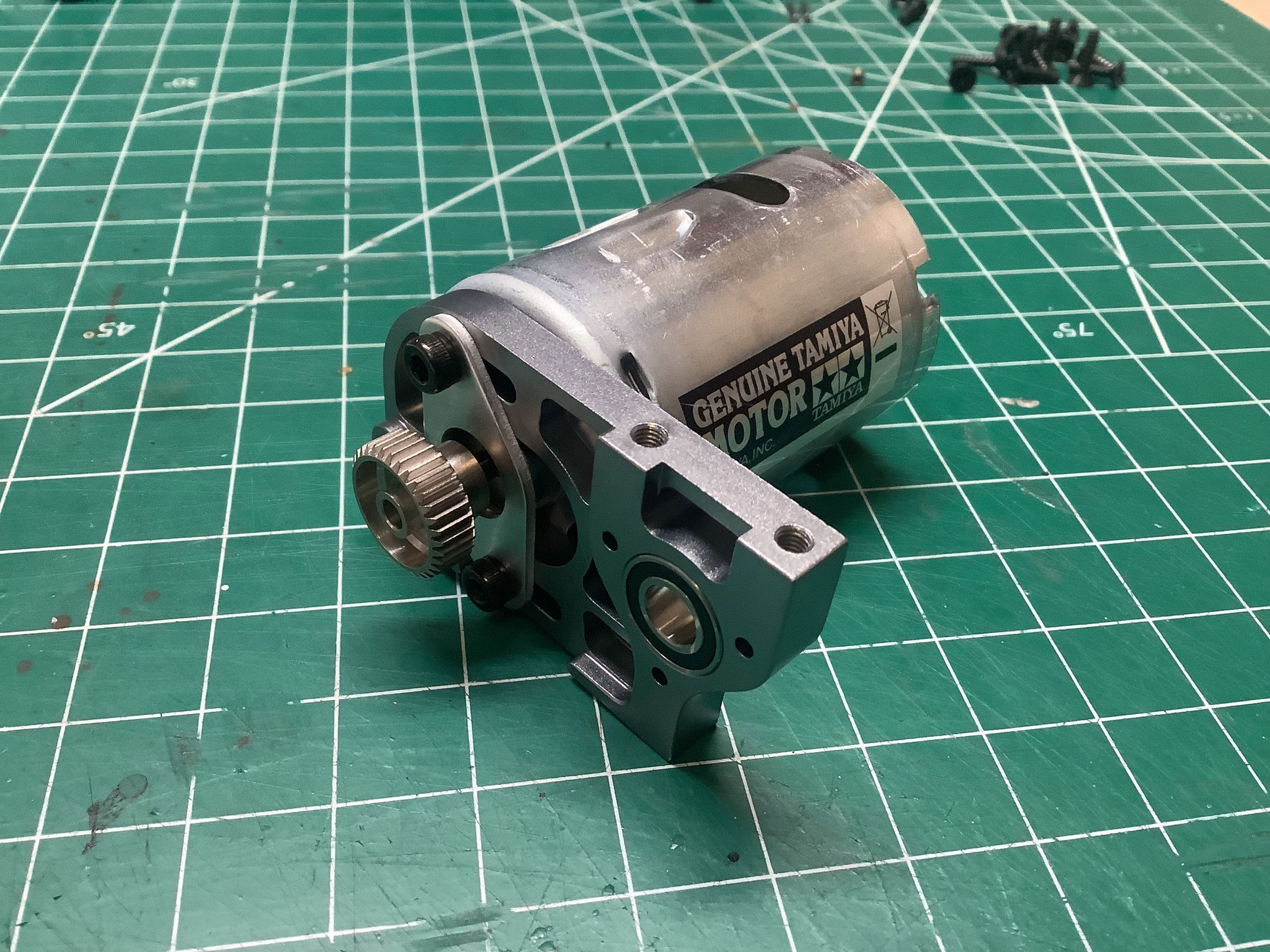
Step 7 builds the motor mount. This chassis kit doesn't come
with a motor, but the manual recommends a Dyna Run Racing motor. I
didn't have one of these, and if I didn't I wouldn't have put it in a
shelf queen so I just used a silver can. This could be seen as a
bit of a travesty, but it is just there to show how the chassis is
built. The motor mount is highly machined aluminum with a steel
support plate. The mounting holes are slotted which means the
whole motor slides side to side to adjust the gear mesh rather than just
rotating on one screw. The pinion is 34T 0.4 Mod (metric).
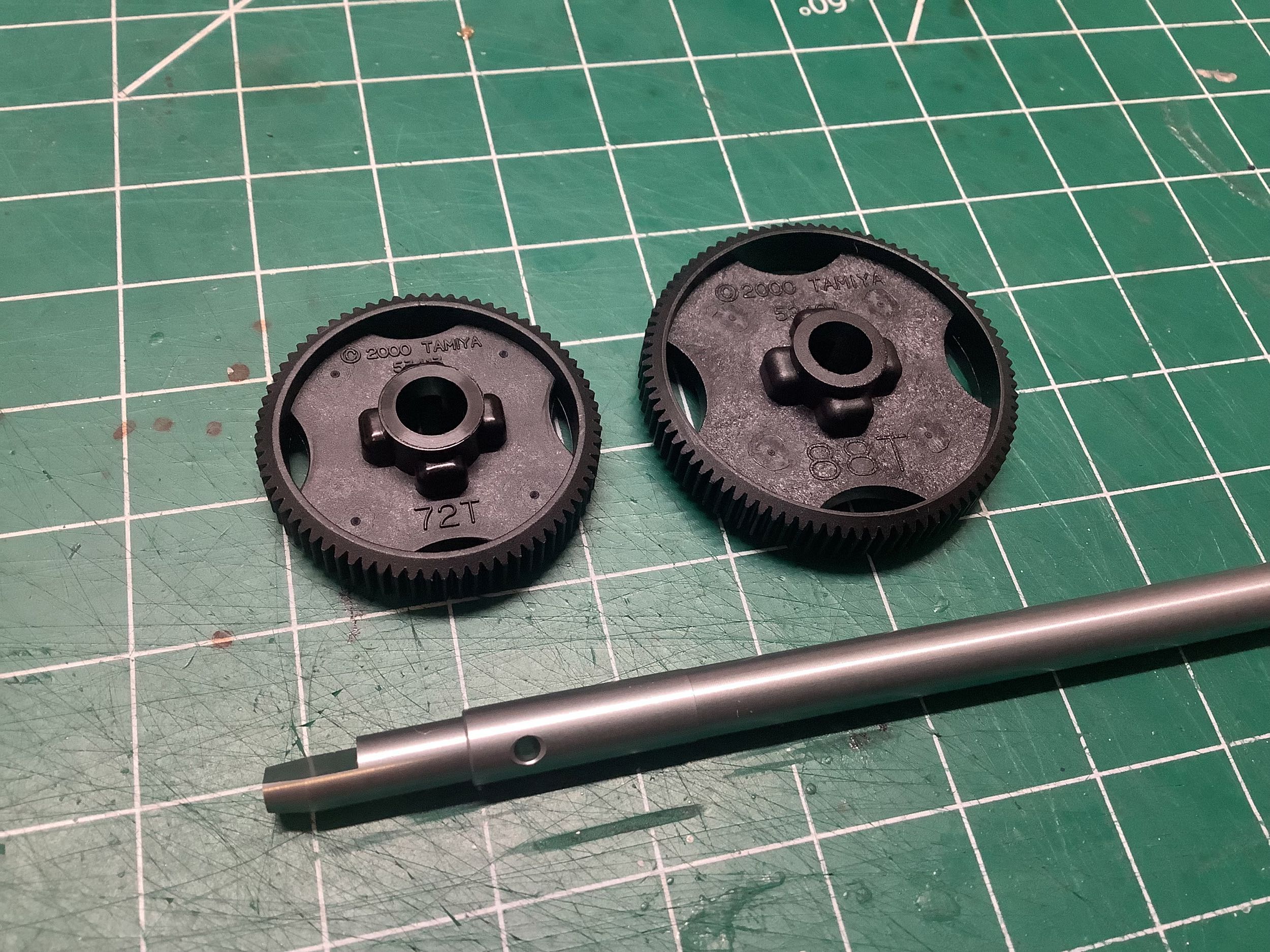
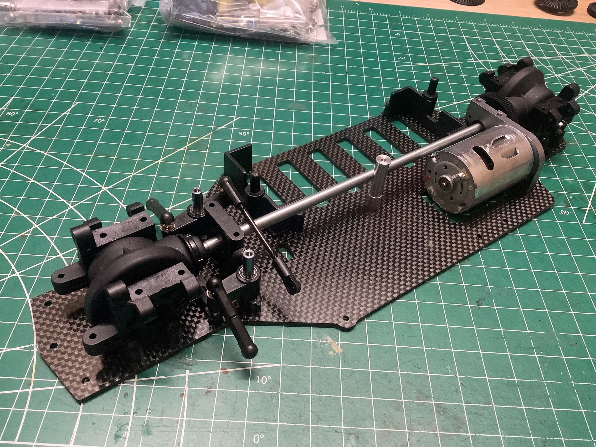
The spur gear sits directly on the central aluminum drive
shaft. The kit comes with two 0.4p spur gear options, 72T and
88T. The larger 88T is used by default giving a lower top
speed. The rear differential housing and the drive shaft have to
all be installed at the same time which is a bit tricky and is
accomplished in Step 8. The steering cranks sit under the drive
shaft so need to be installed first even though they are in the same
step. One obvious difference between a shaft drive model and a
belt drive model is that it makes sense to install the motor
longitudinally (parallel to the drive shaft) for shaft drive compared to
laterally (parallel to the axles) for belt drive. The makes the
motor weight for a shaft drive model closer to the center. The
front differential is installed in Step 9, shown here after both steps
were completed. Step 10 is just adjusting the gear mesh.
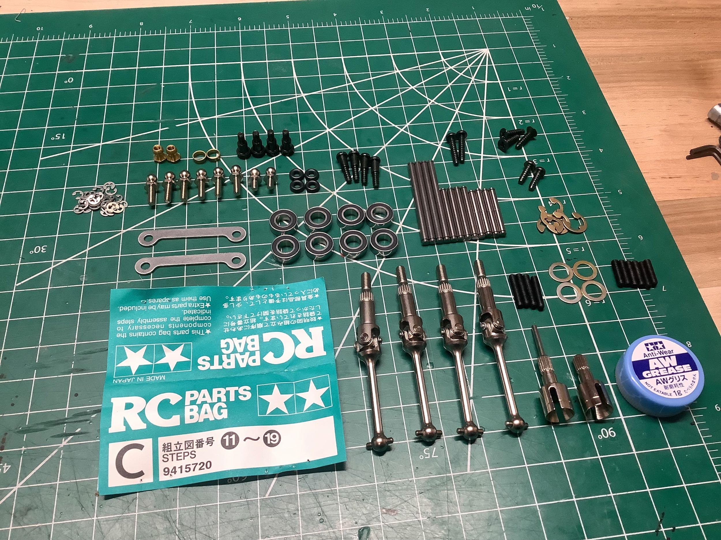
Hardware bag C contains the hardware for Steps 11-19 which install the suspension. There's a lot of good stuff here.
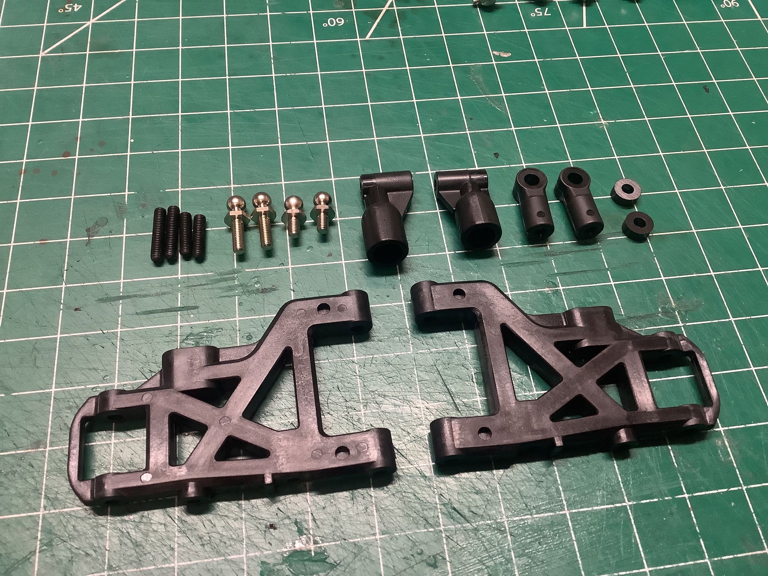
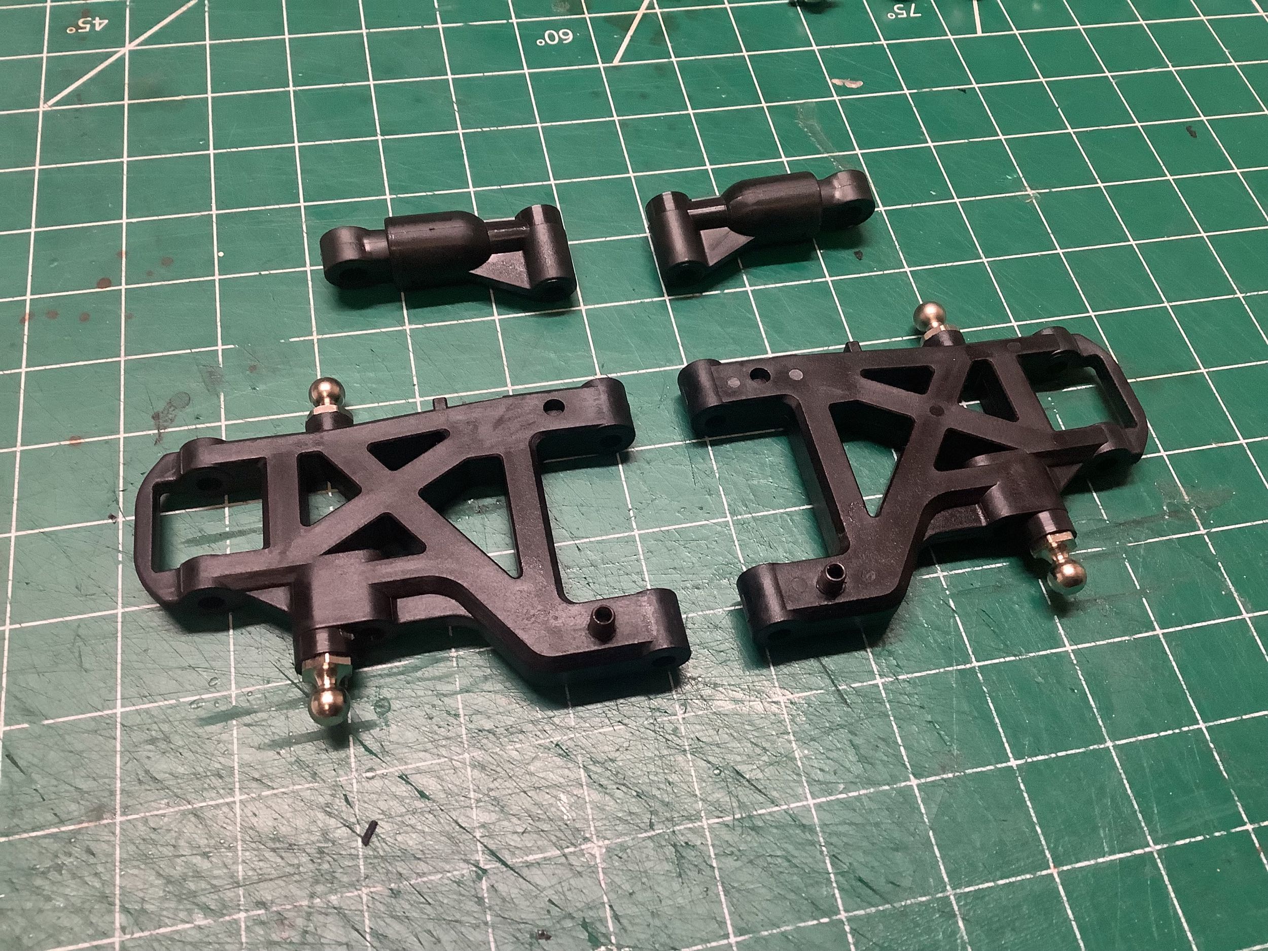
The camber links come from the E parts tree and the suspension arms
come from the M parts tree, both of which are new for the Evo. The
camber links are not simple threaded rods with ball joints at the end,
instead they are more rigid telescoping assemblies I like much
better. They have only one rotational degree of freedom (up-down)
which gives the wheels much better longitudinal support. The
length can only be adjusted by rotating in 180º increments. The
lower arms are thick and highly braced. Step 11 assembles these
parts.
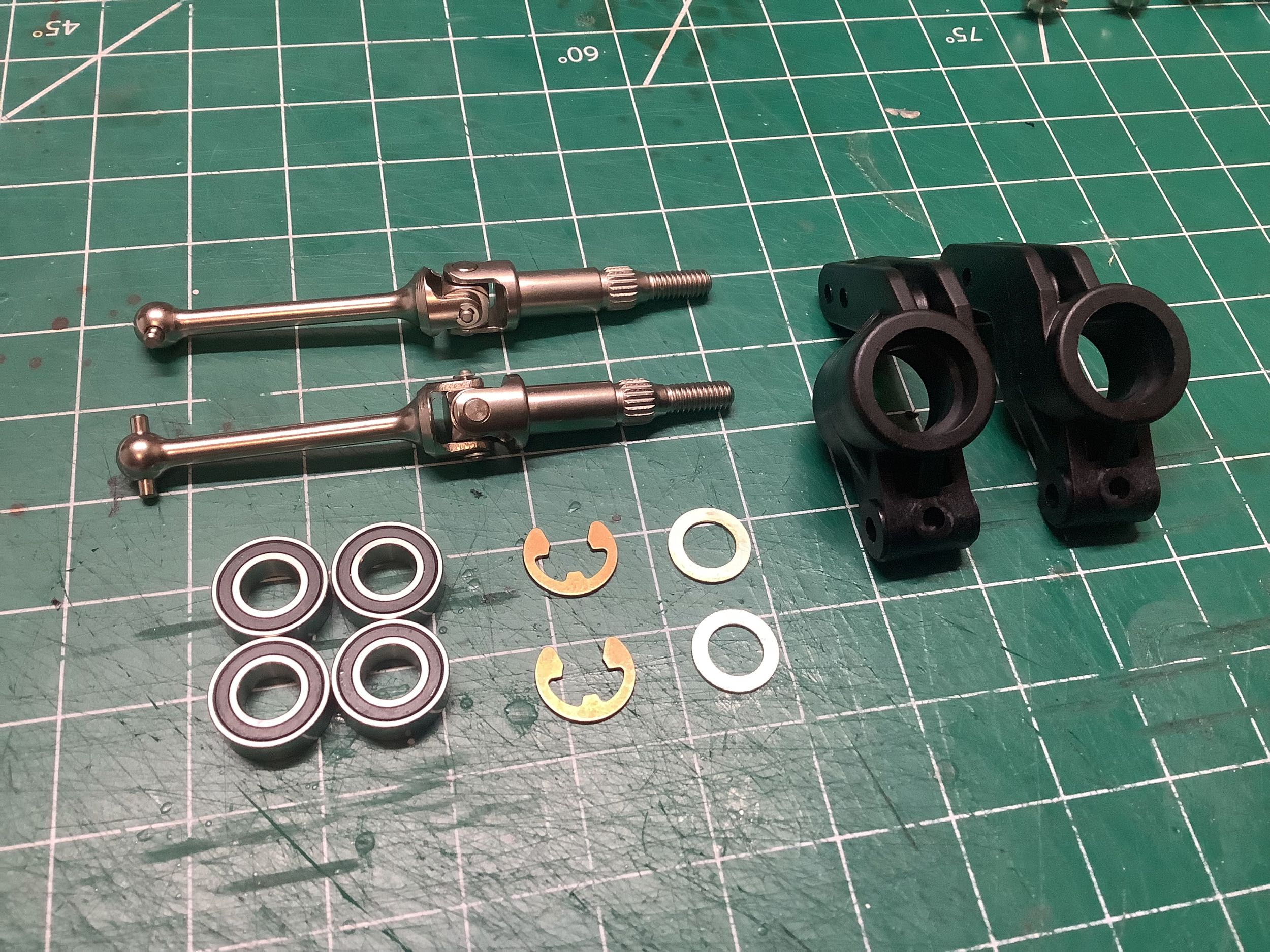
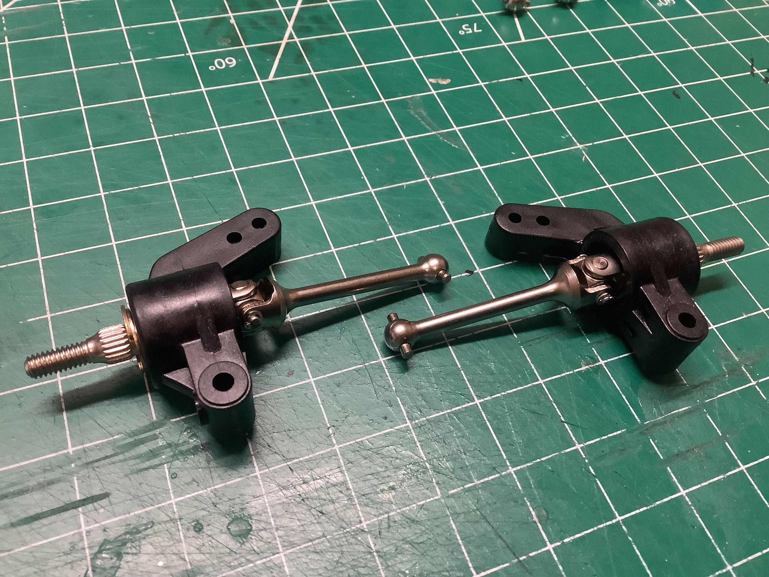
Step 12 assembles the rear uprights. The plastic uprights
themselves are from the TGR. The axles are pre-assembled
universals which an unusual spline on the output (like a Clodbuster)
instead of a cross pin. This is much stronger, but also much more
expensive. Given that touring cars don't need to transfer all that
much torque, it makes sense that this design detail didn't last long
until it was replaced by the more common design. They sure are
nice parts though.
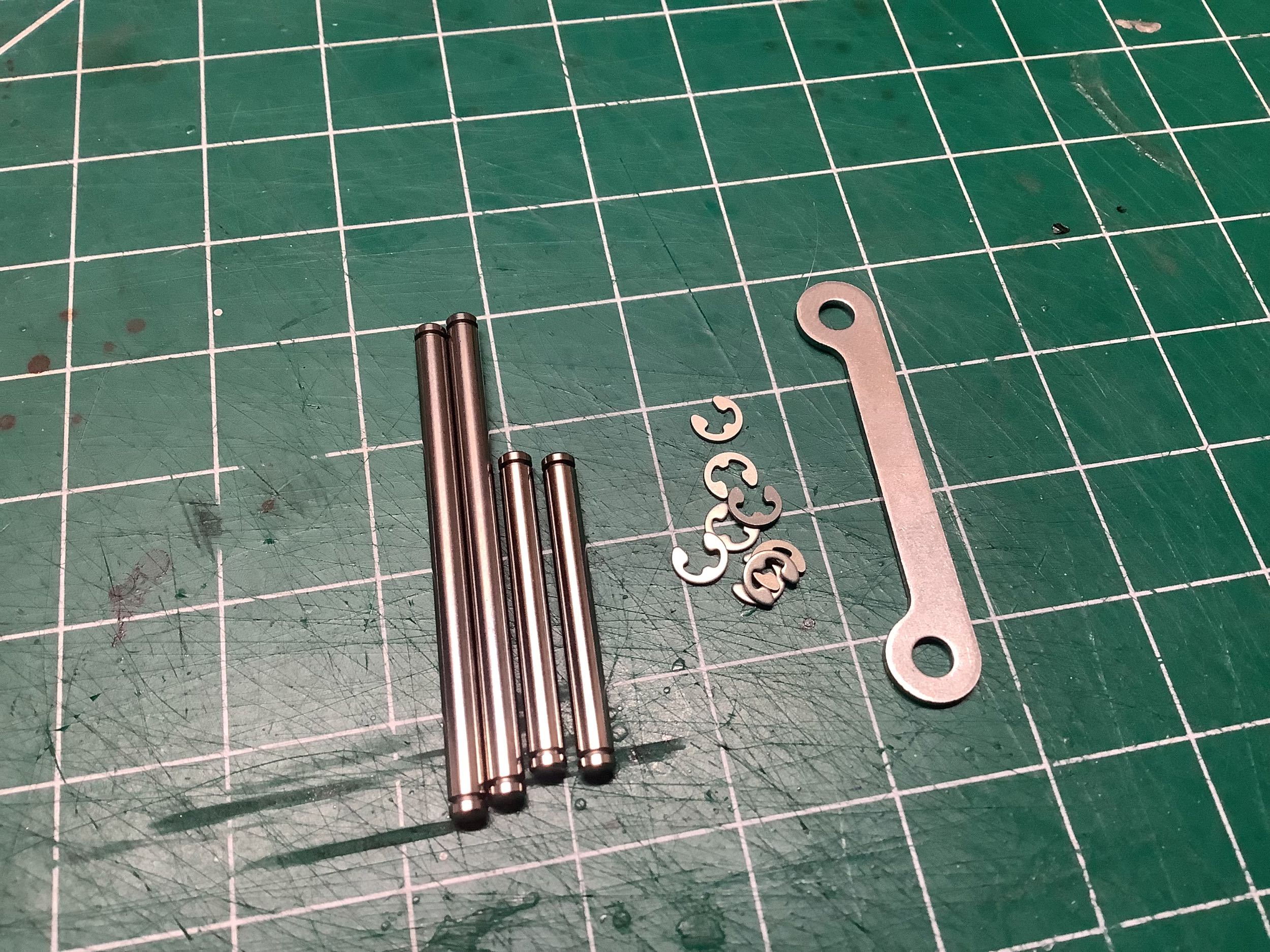
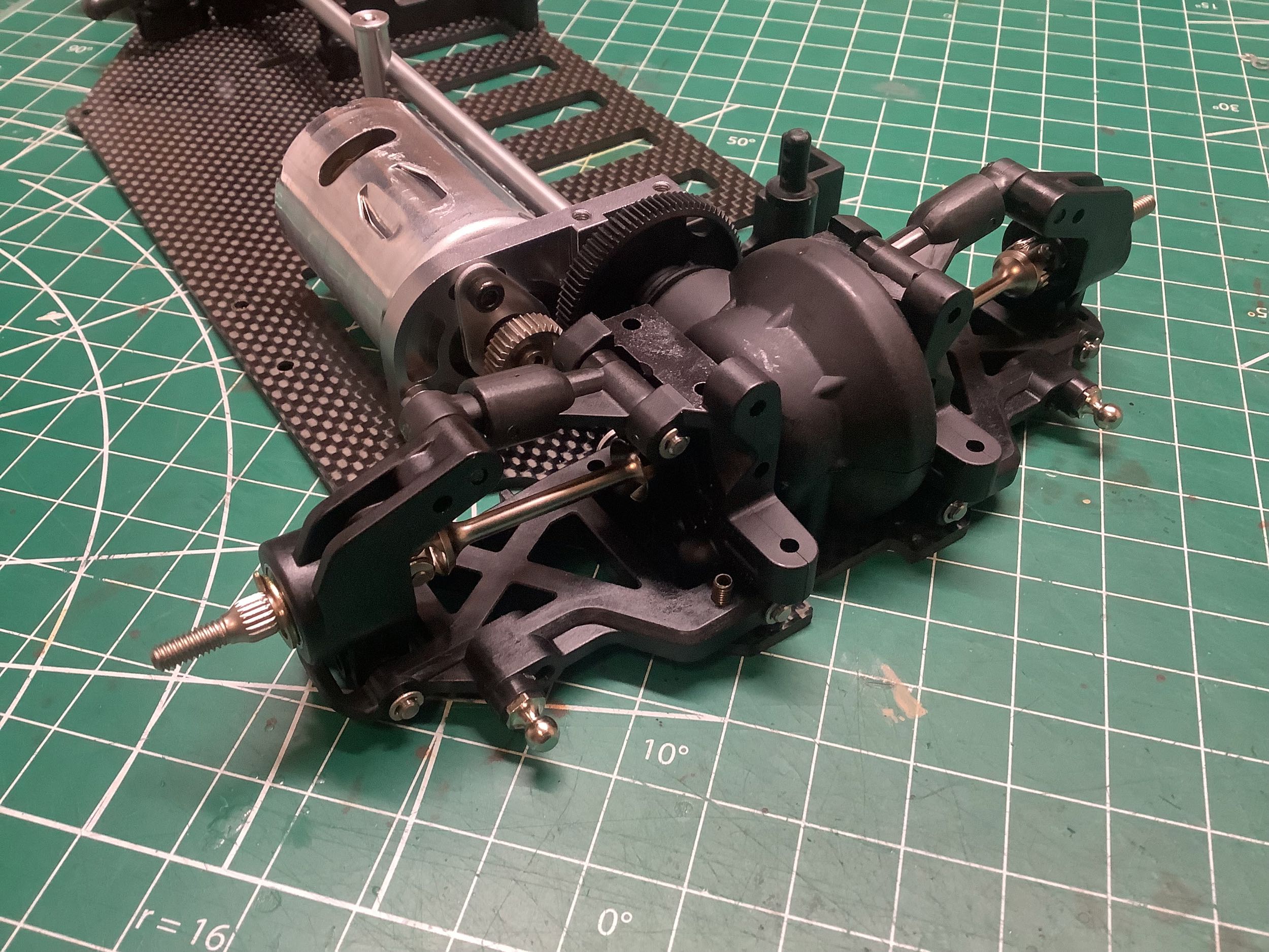
The suspension arms attach with 3mm hinge pins retained with E-clips
which are installed in Step 13. The hinge pins pass directly
through holes in the bulkhead which means there is no way to adjust
anti-squat angle, toe angle, or roll center. Because the hinge
pins are only supported by plastic, a steel "support stay" is used at
the front edge. This keeps them properly spaced and absorbs any
loads from impacts at the wheels. The uprights also attach with
hinge pins installed in Step 14. Note that the upper arms are much
shorter than the lower arms resulting in camber gain as the suspension
is compressed.
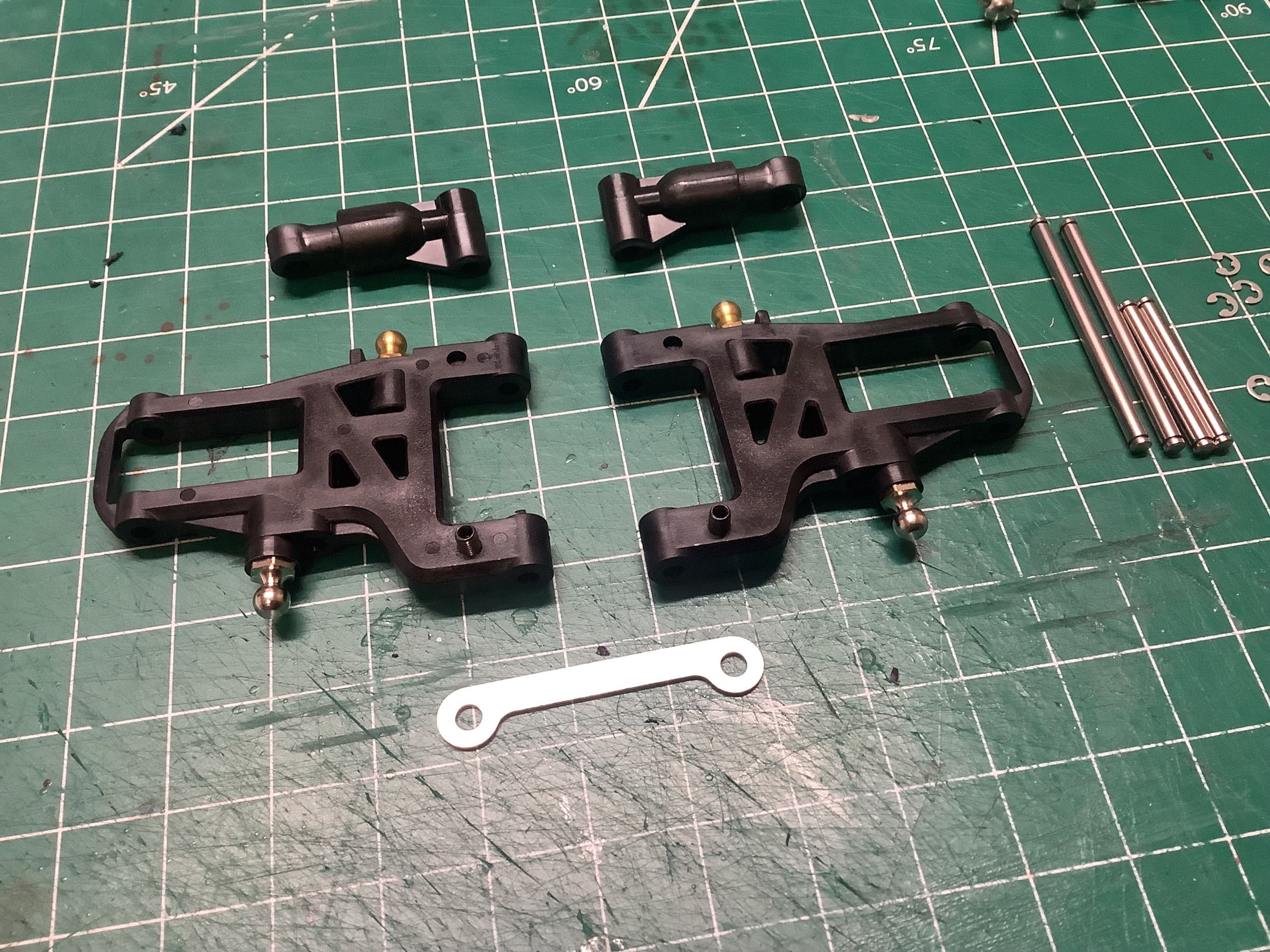
The front arms are built in Step 15 and go together just like the
rear arms. They taper to a much narrower section at the outer edge
compared with the rear arms. They are installed in Step 16.
Like the rear, there is very little suspension geometry
adjustment. The toe can be adjusted with the steering link
lengths, and the camber with the upper link lengths.
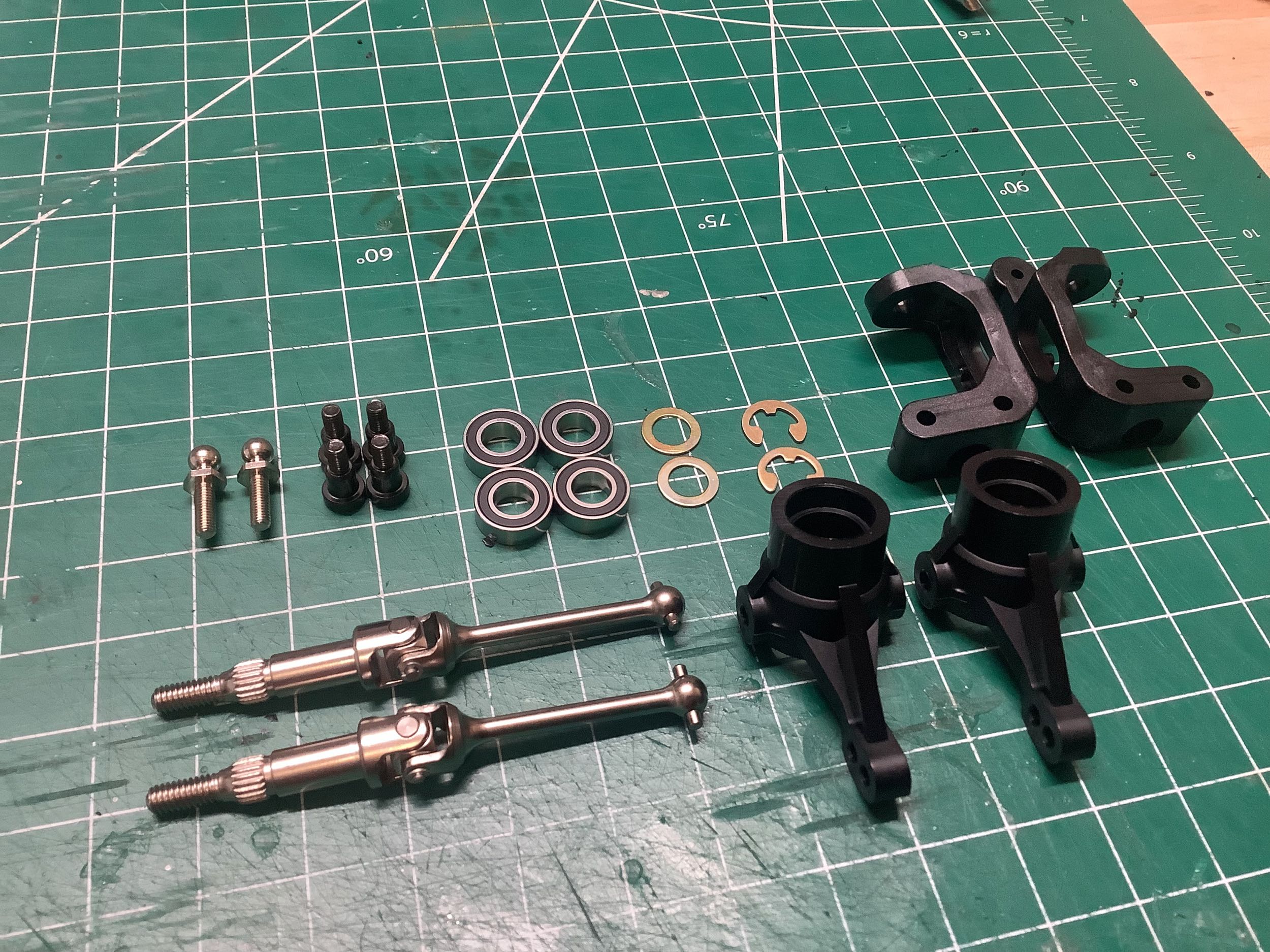
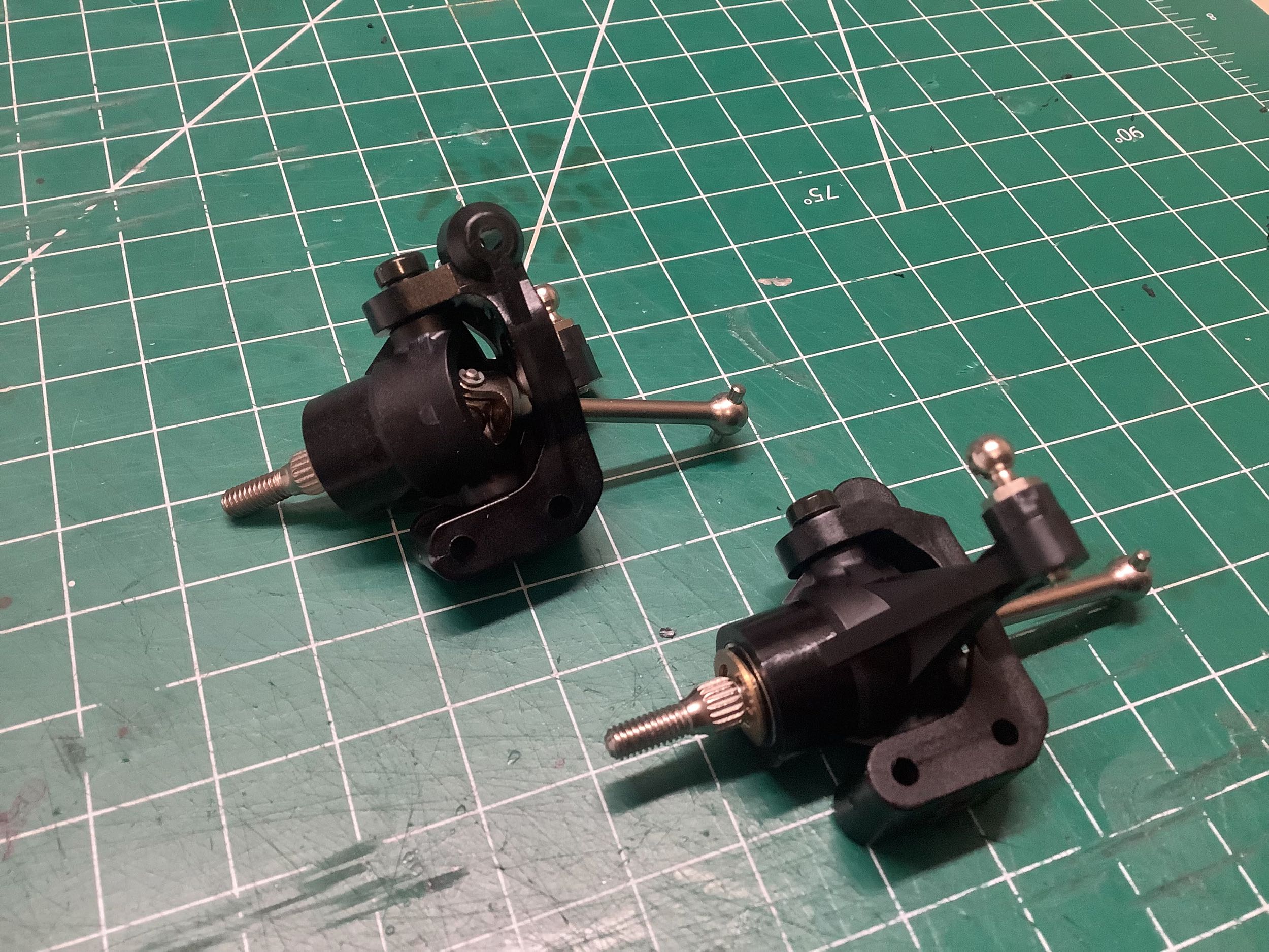
The front universal axles are identical to the rear right down to the
lengths. The C-hubs and knuckles are from the TGR. Left and
right knuckles are identical, while left and right hubs are
mirrored. These assemblies are built in Step 17.
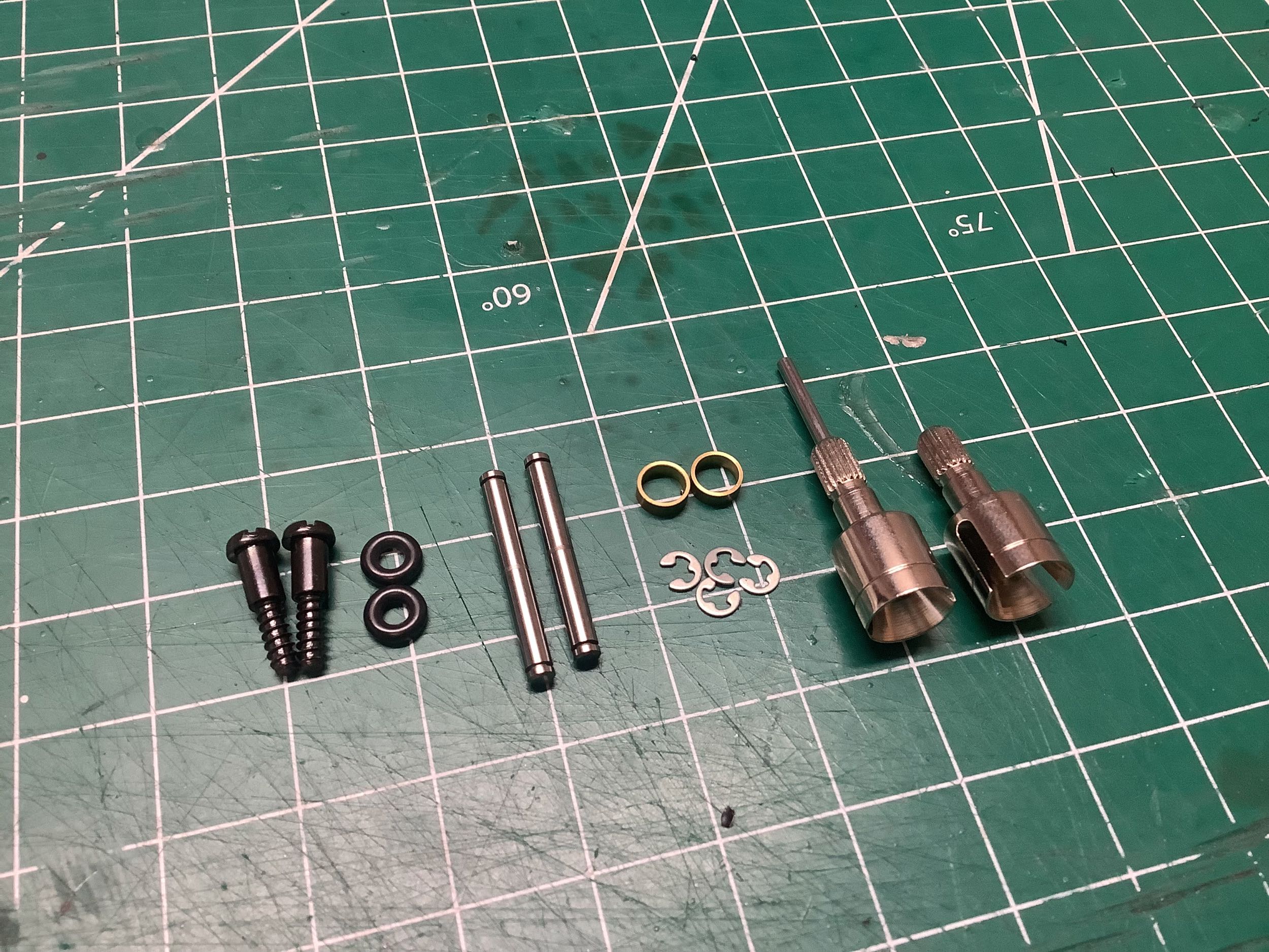
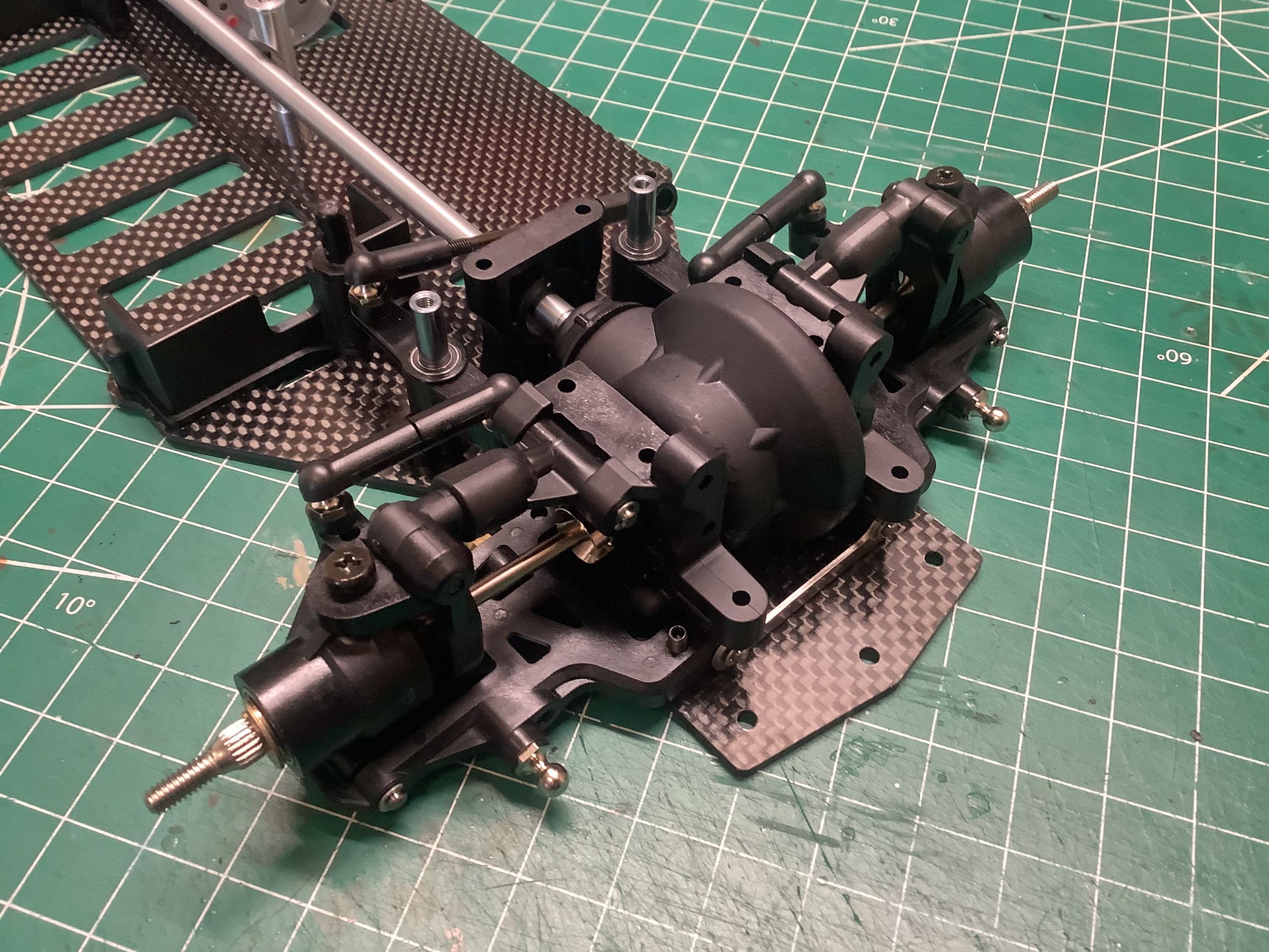
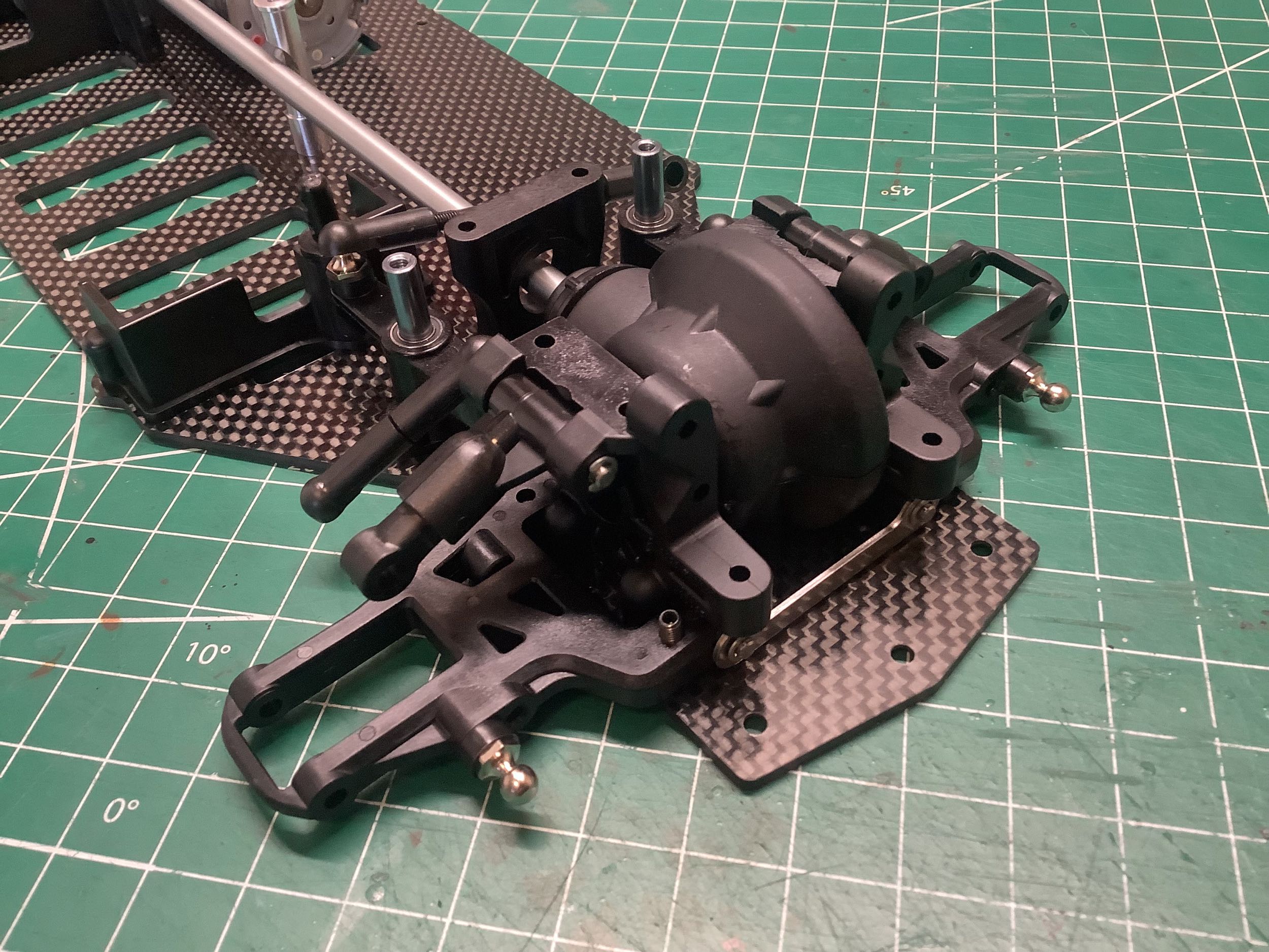
Step 18 installs the front suspension onto the chassis using hinge
pins at the lower end and step screws at the upper end. The
steering links are also snapped onto the knuckles at this point.
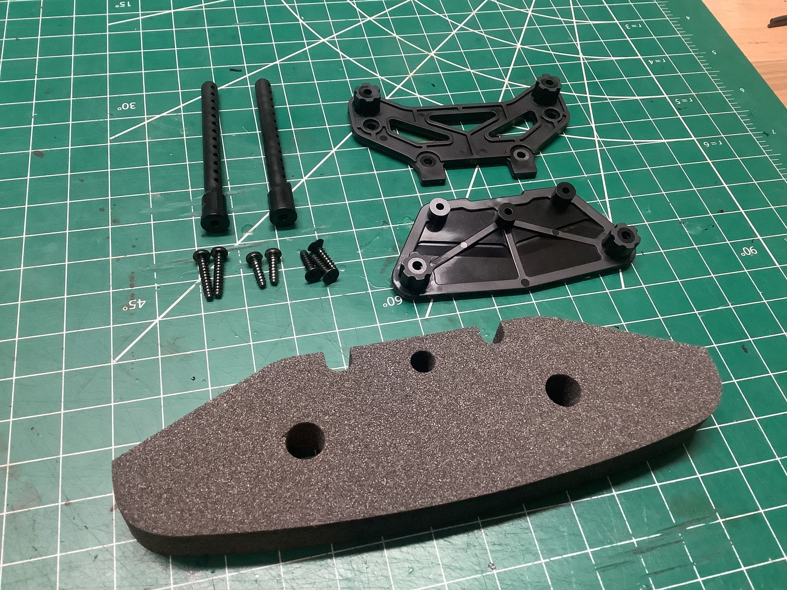
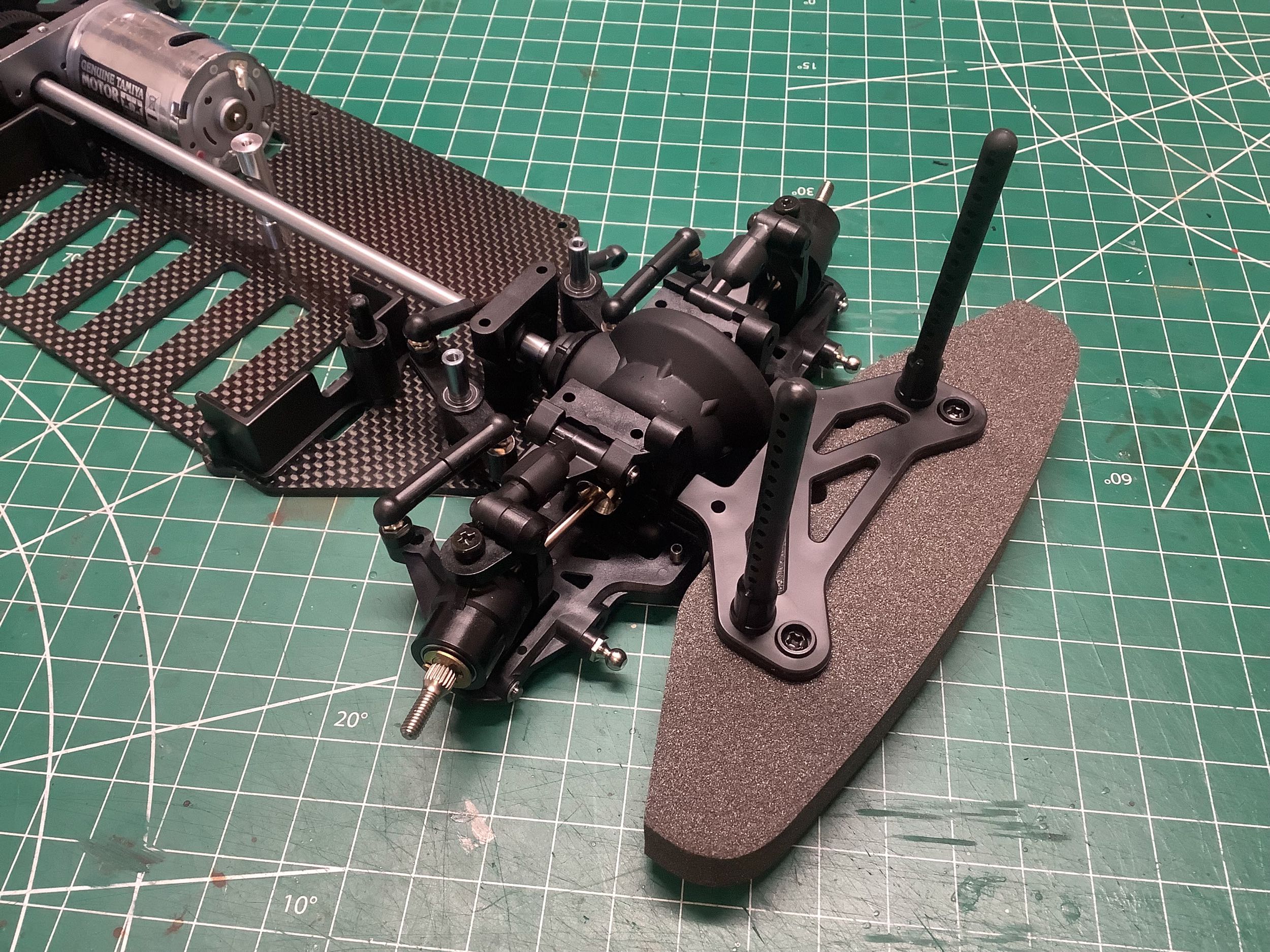
The final step of hardware bag C is Step 19 which installs the front
bumper and body mounts. The bumper supports are plastic and new
for the Evo.
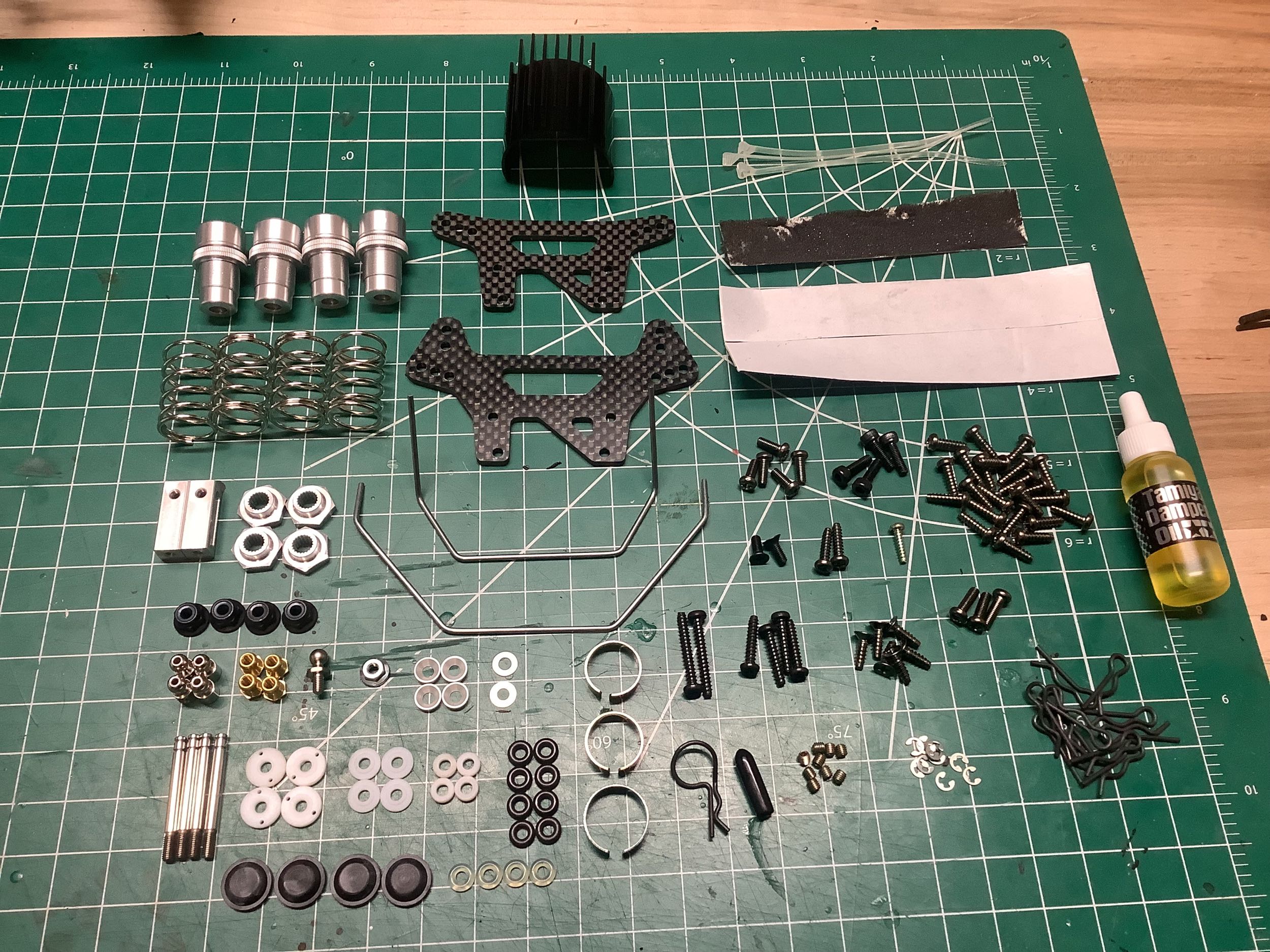
Hardware bag D contains the parts for Steps 20-36, which sounds like a
lot. Mostly this involves building and installing the shocks and
the electronics.
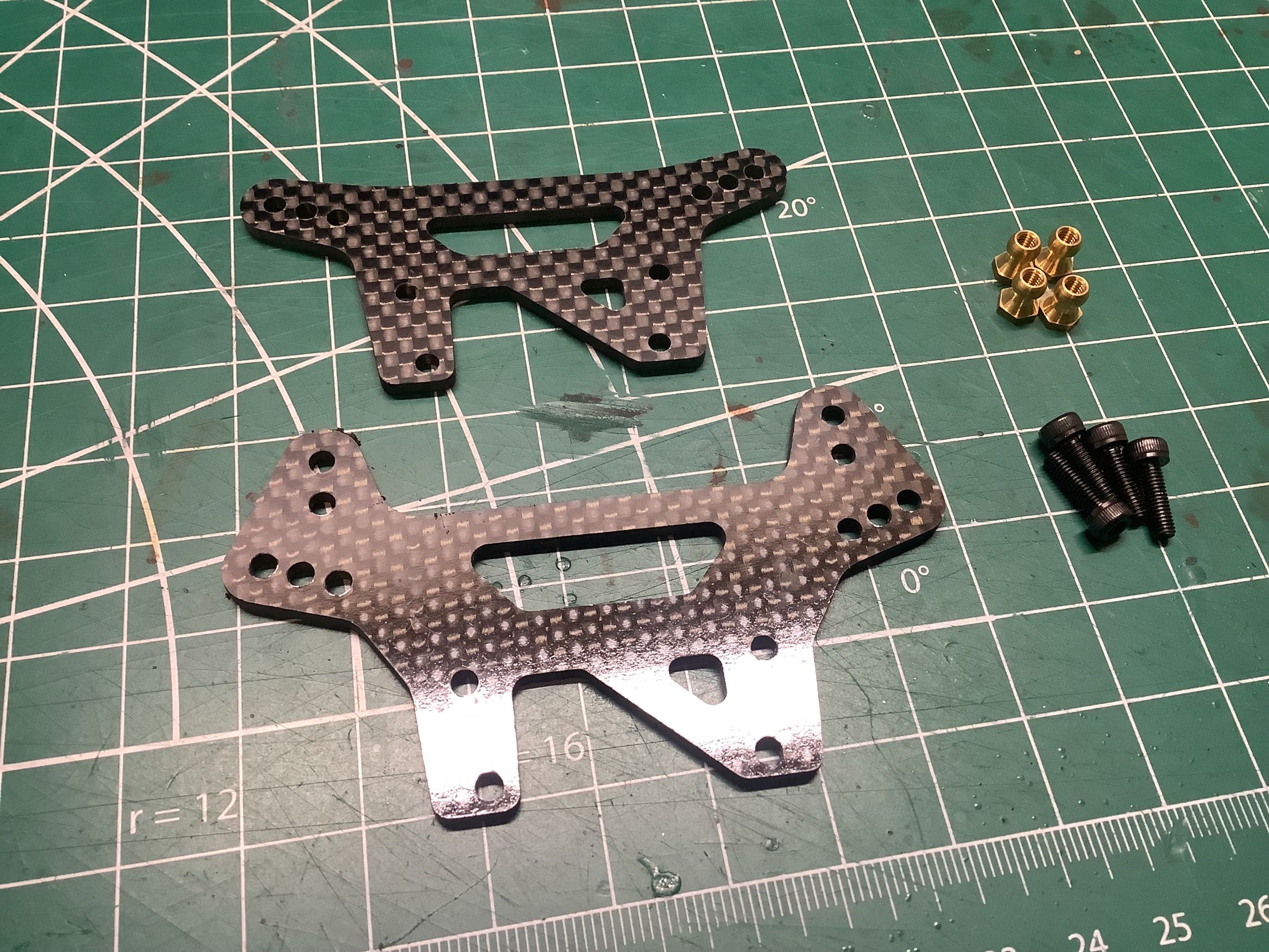
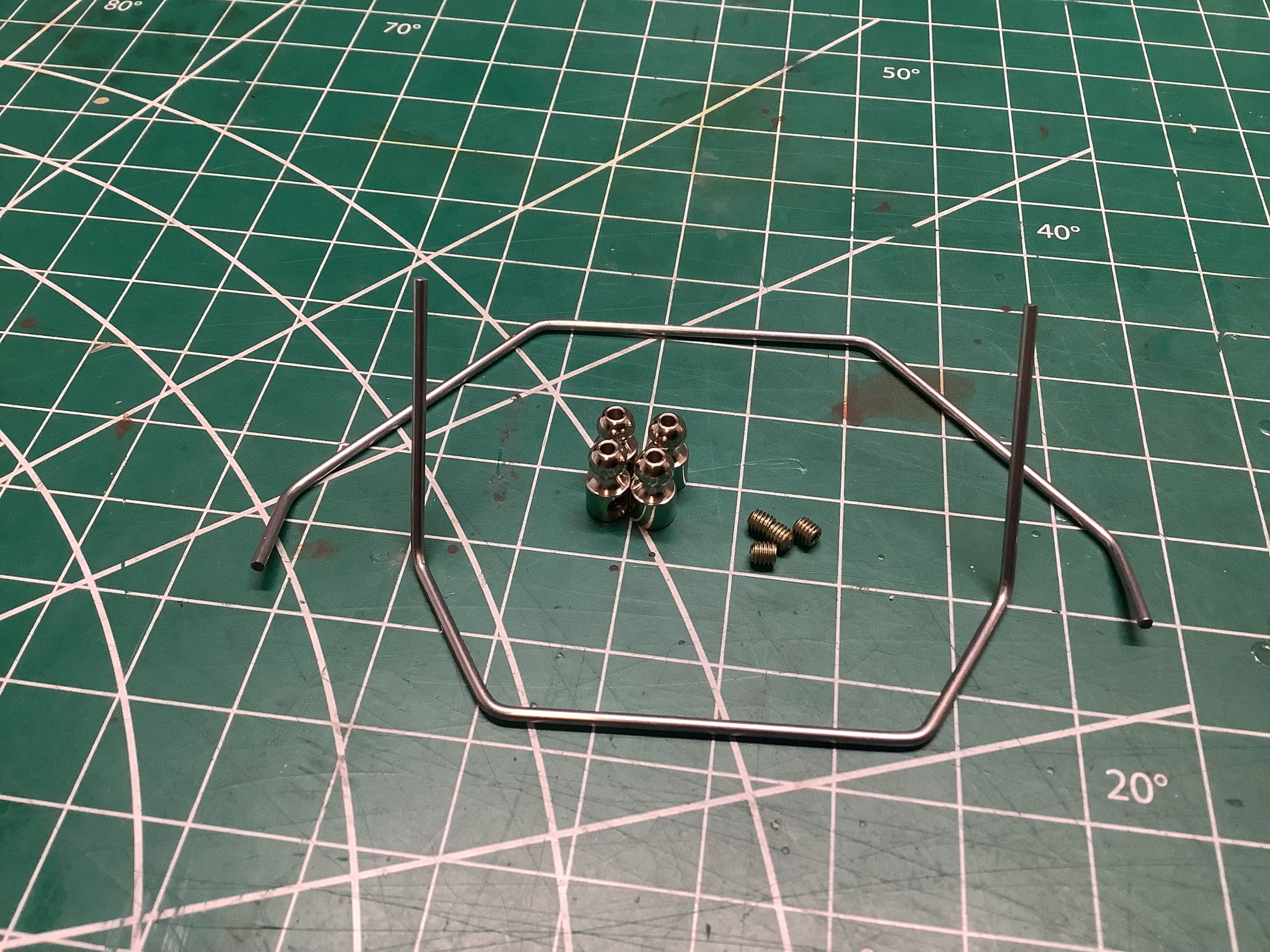
I'm combining a couple of steps in the photos here. Step 20
prepares the shock towers by attaching the ball studs. These are
complex shaped, asymmetric designs. The triangular notch fits over
the differential ring gear. Step 23 prepares the sway bars which are
bent steel.
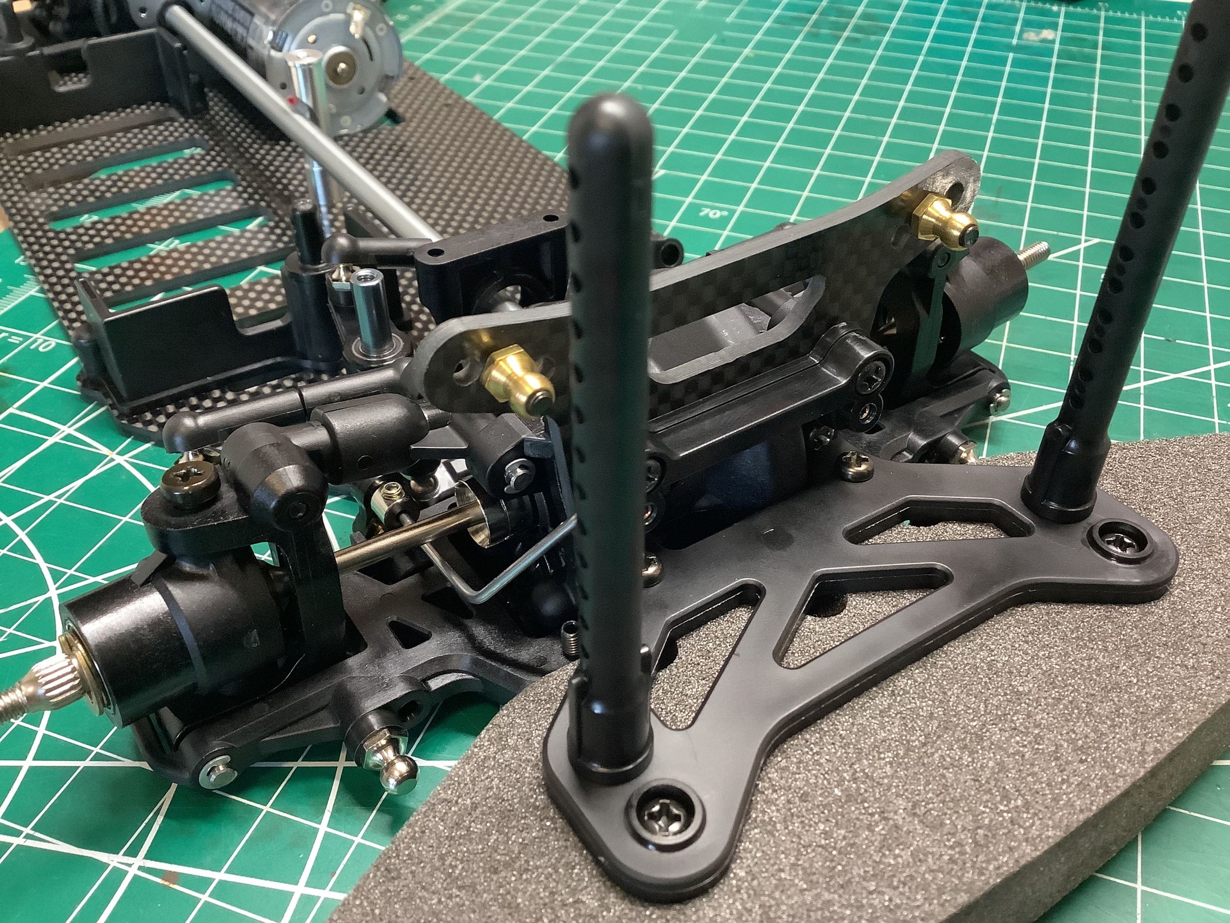
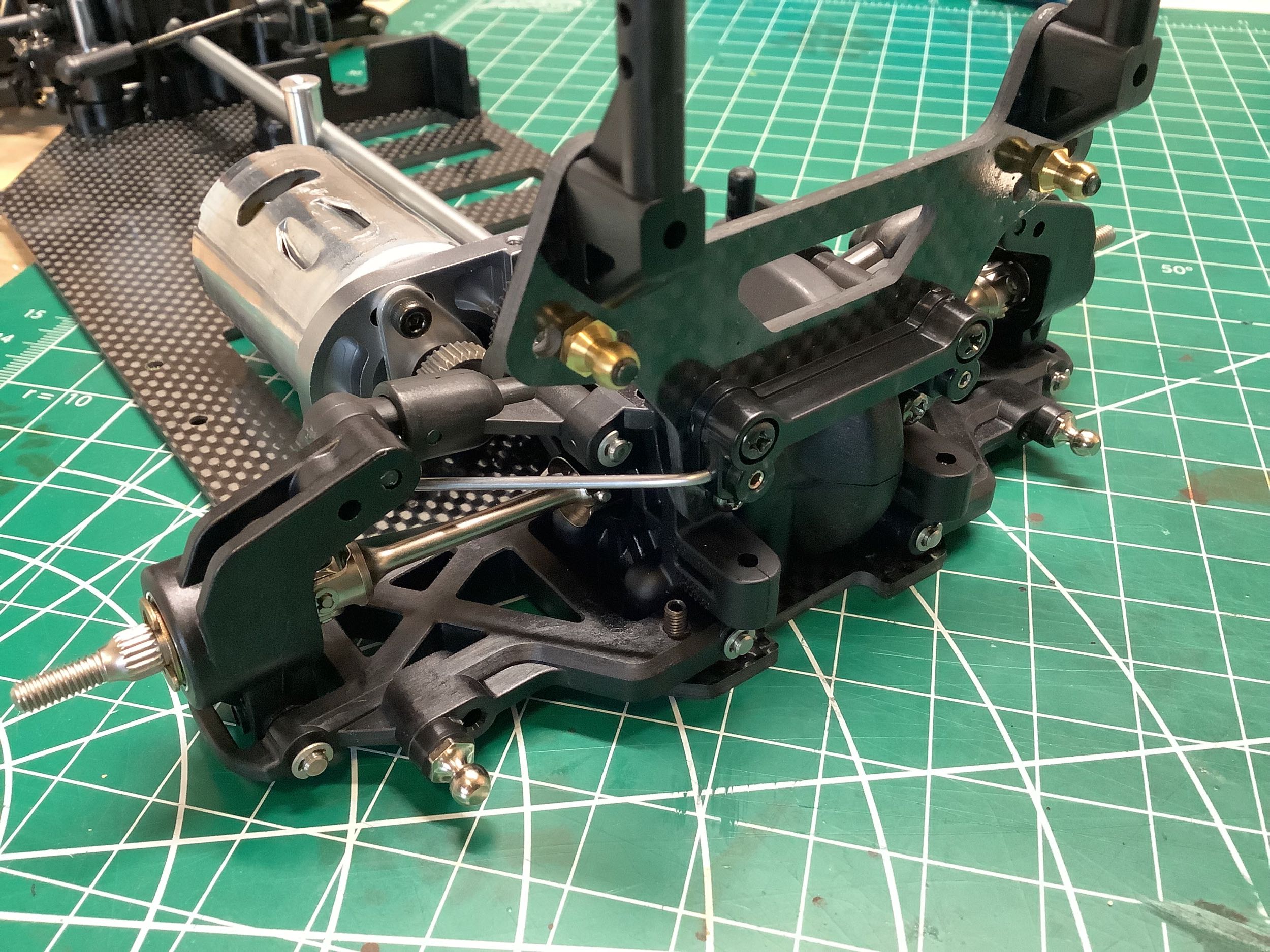
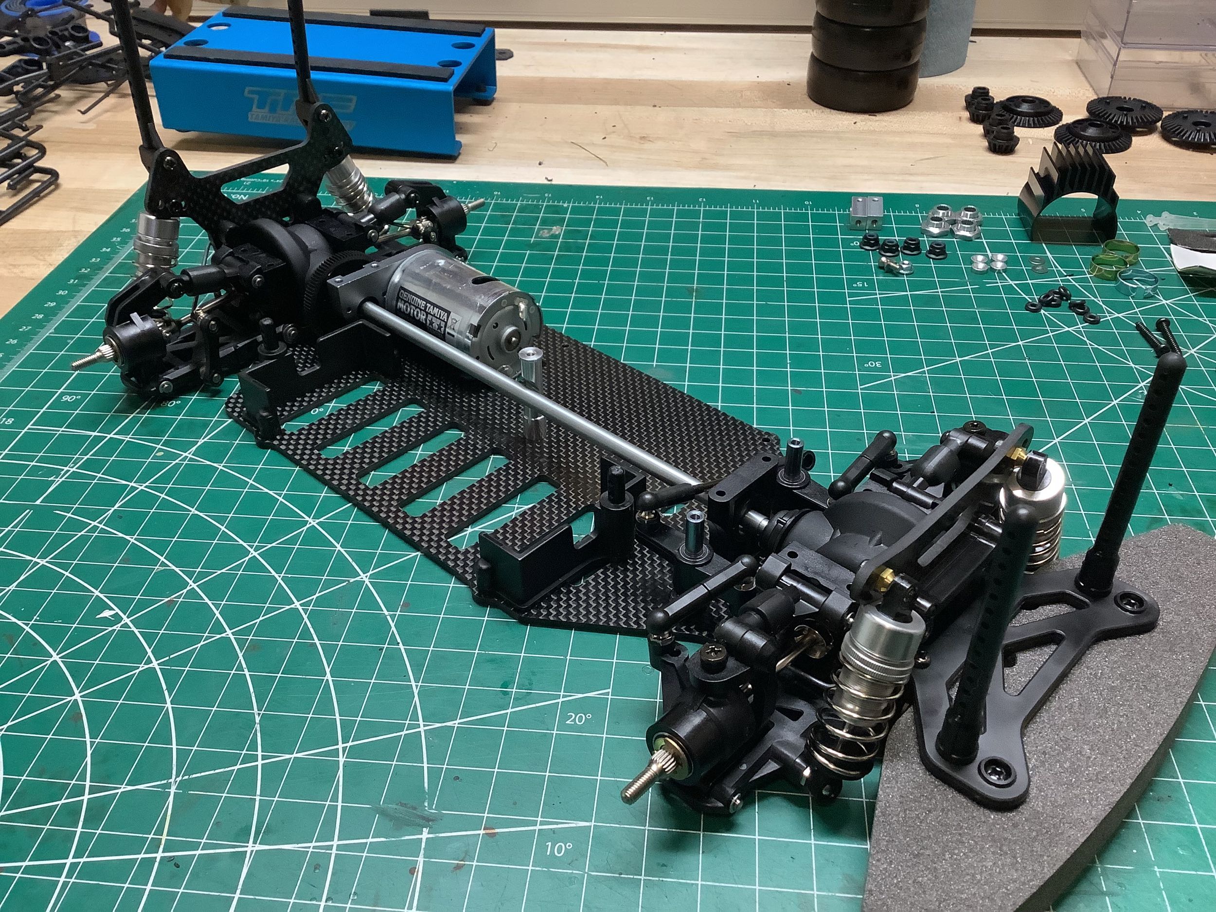
Steps 21, 22, and 24 install the shock towers, sway bars, and rear
body posts. The front suspension is shown on the left and the rear
is shown on the right.
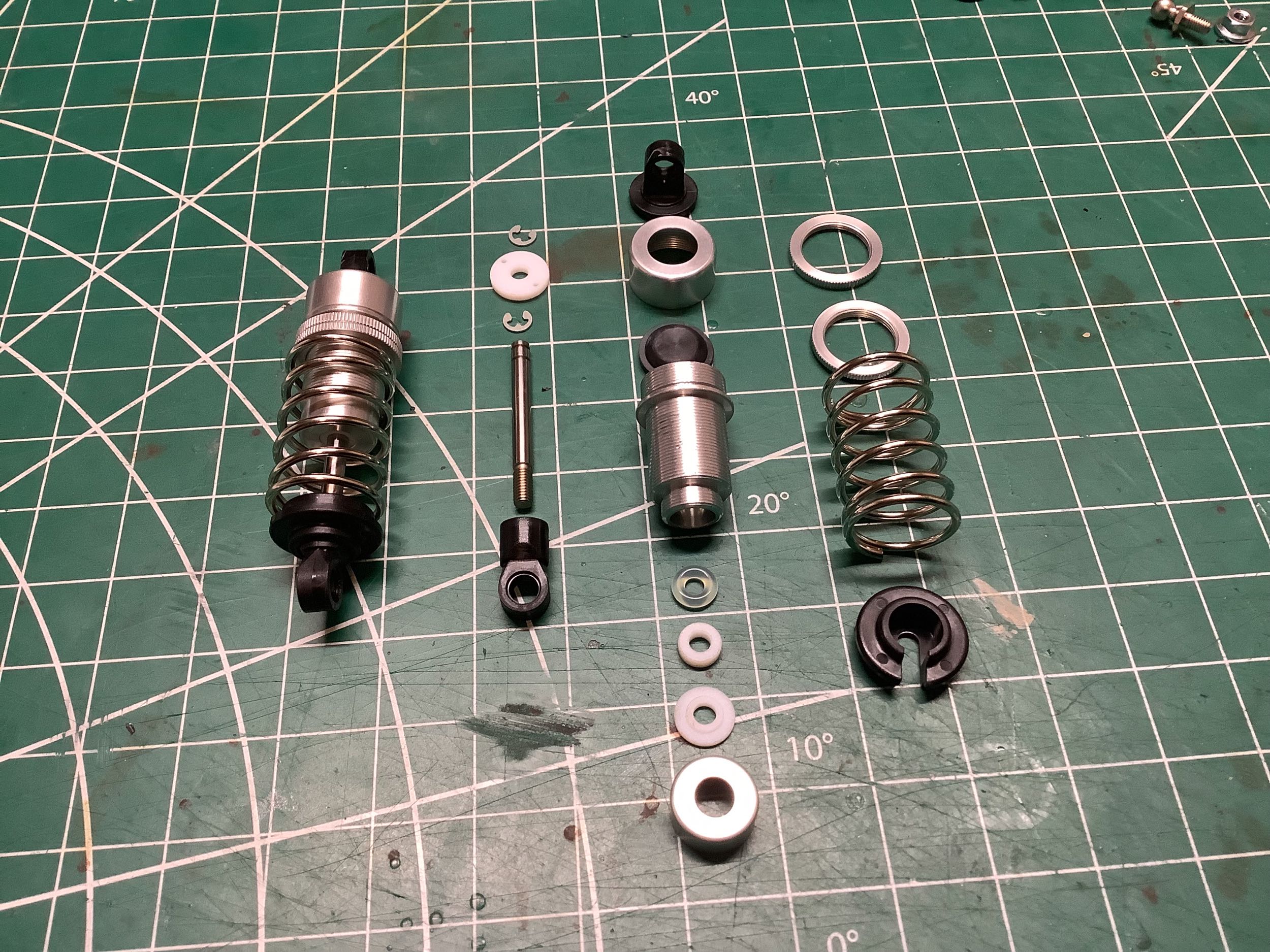
The aluminum shocks go together just like the ones from the TRF
414M. The shock body is externally threaded for spring preload
adjustment, and the design uses two threaded collars that jam together
to lock them in place. All four are identical and use the same
springs. Steps 26-28 build and fill the shocks, and Step 29
installs them on the chassis. The default preload on the front and
rear shocks is slightly different.
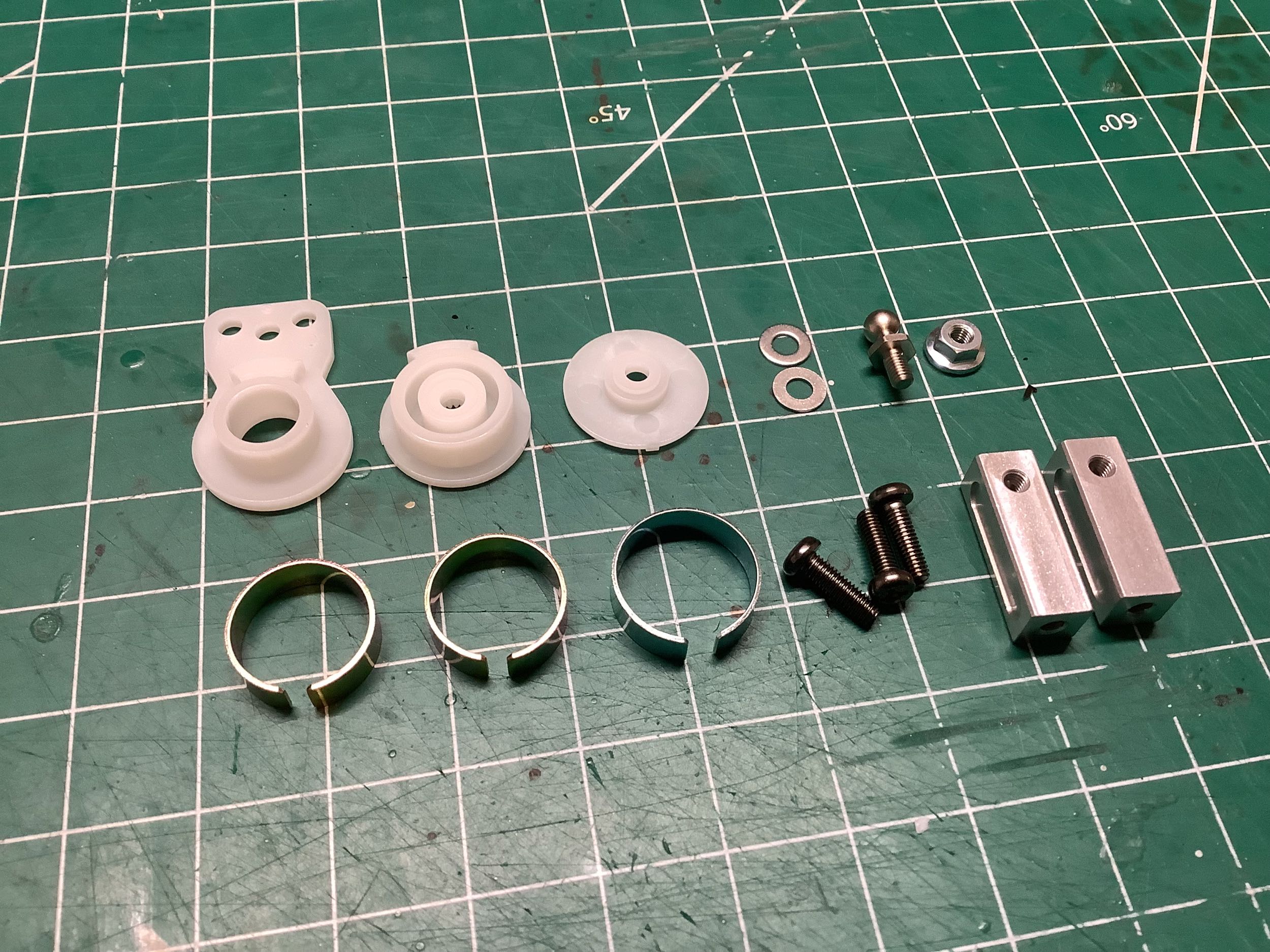
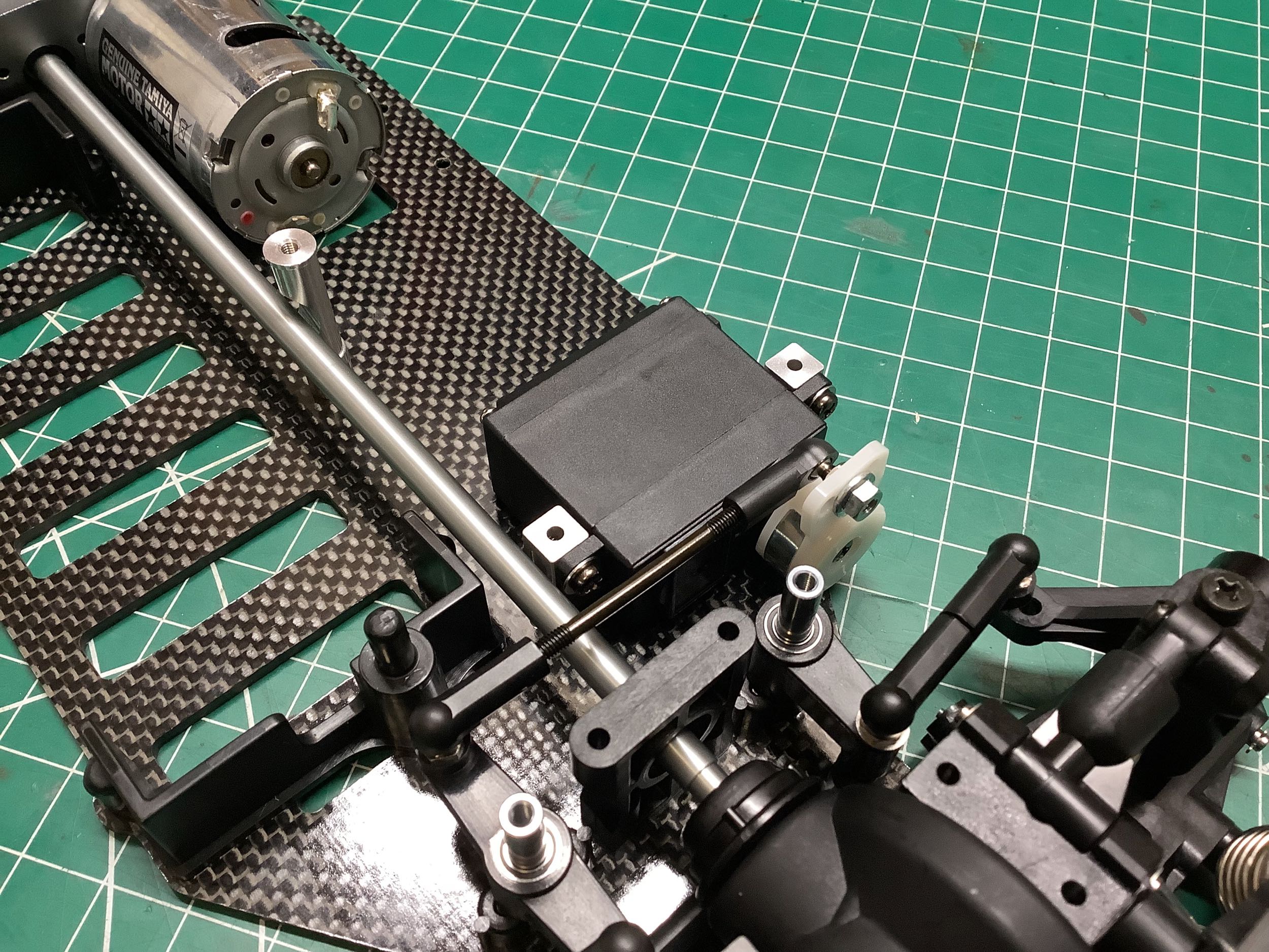
Step 30 installs the high torque servo saver onto the steering servo,
and then attaches the servo to machined aluminum servo mounts.
You can see that the servo link barely clears the drive shaft.
Step 31 installs this onto the chassis. It also shows how to mount
the ESC and receiver which I skipped since I won't be driving it.
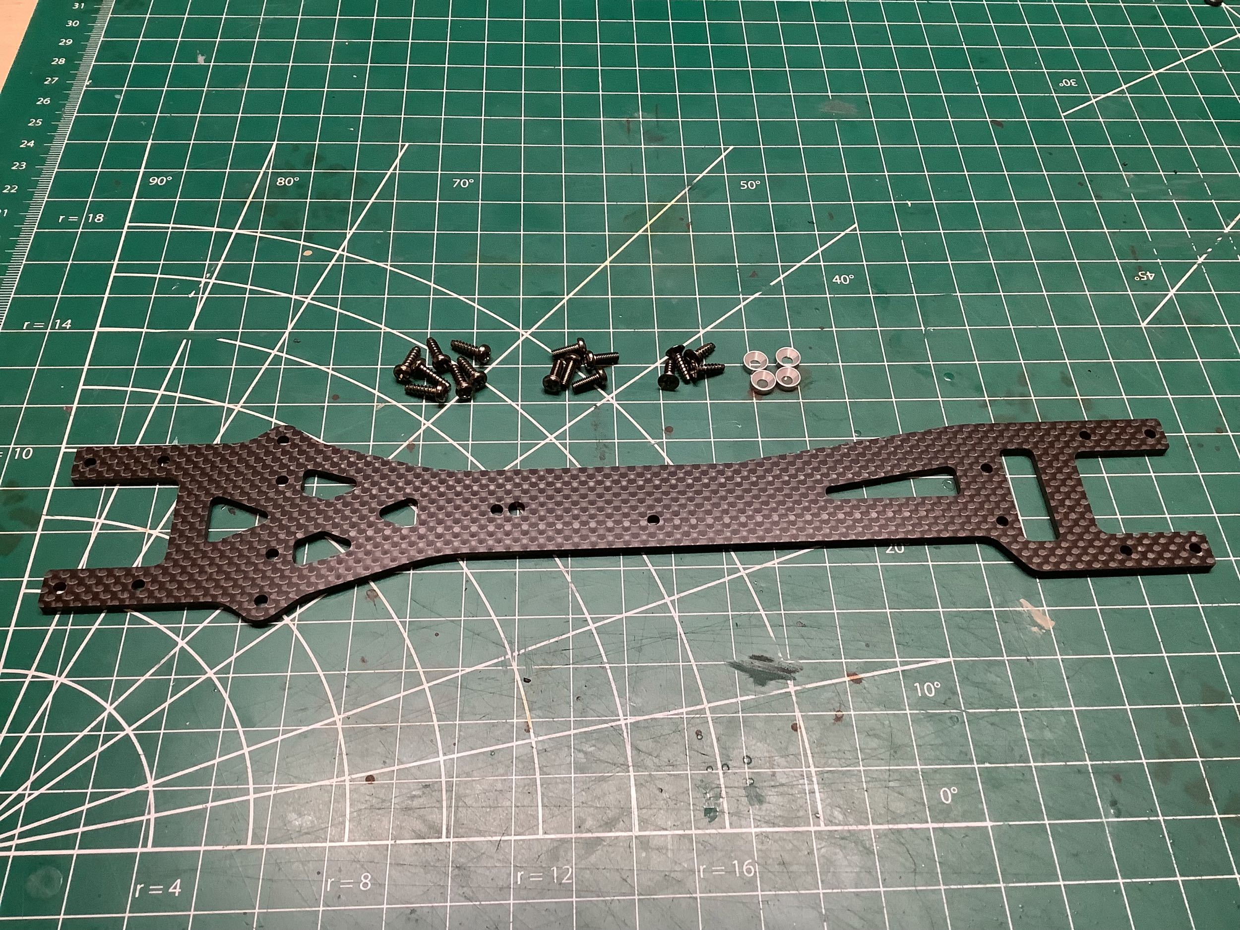
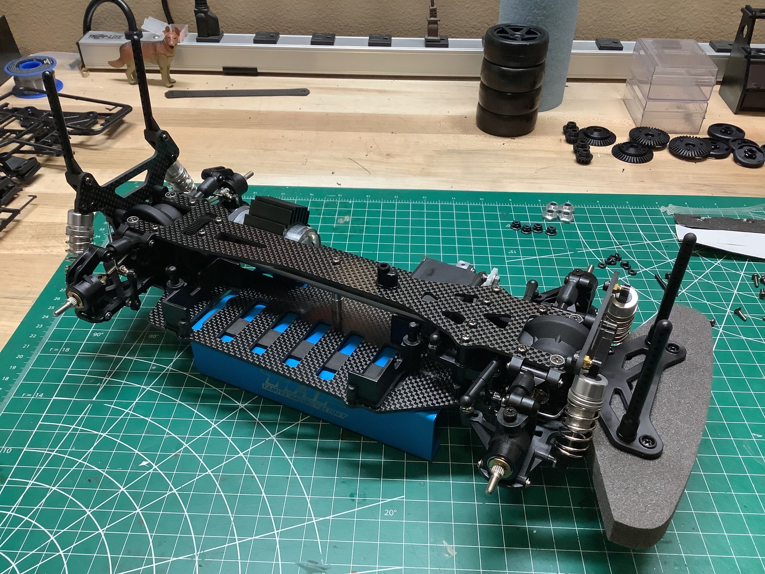
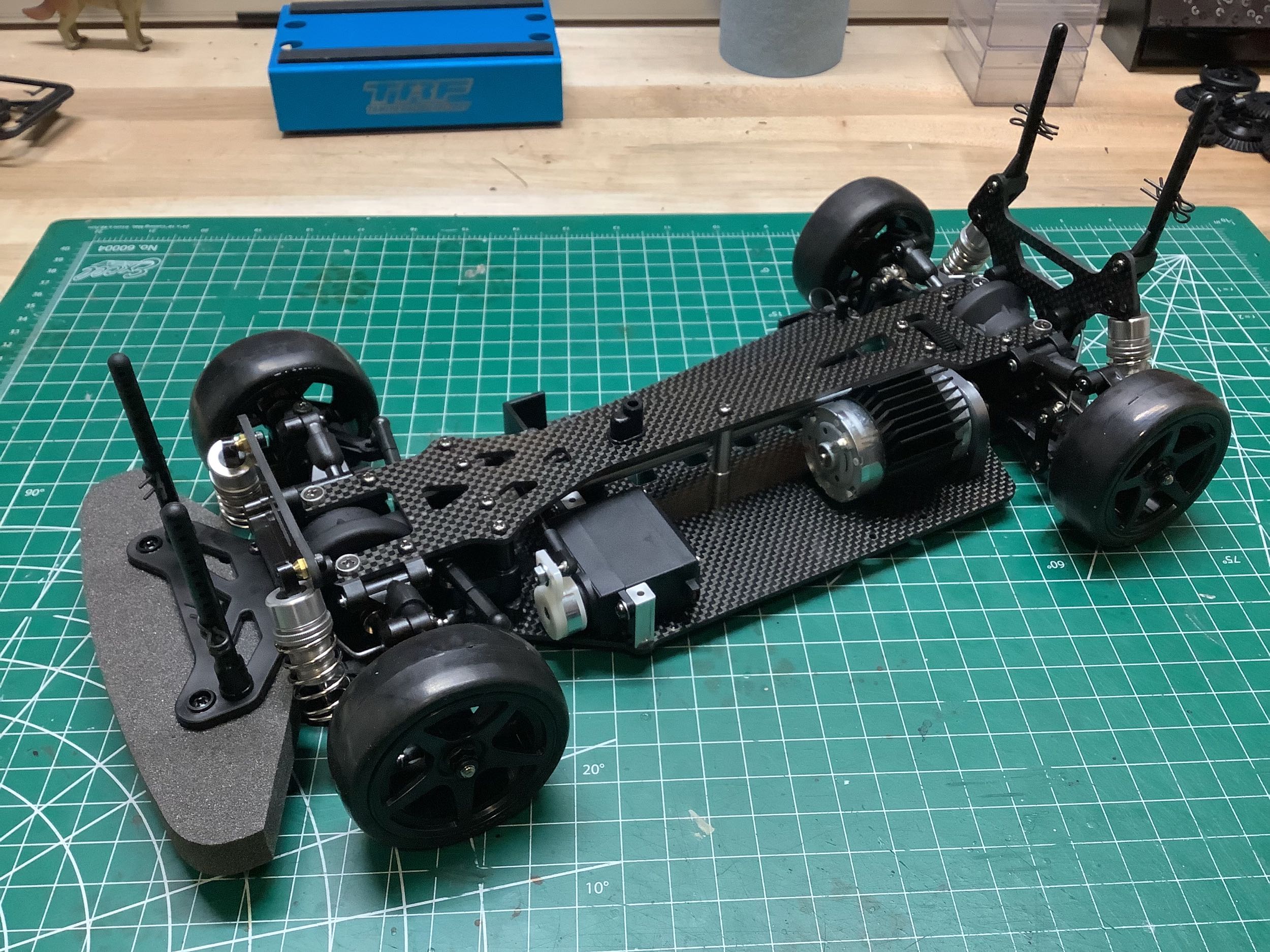
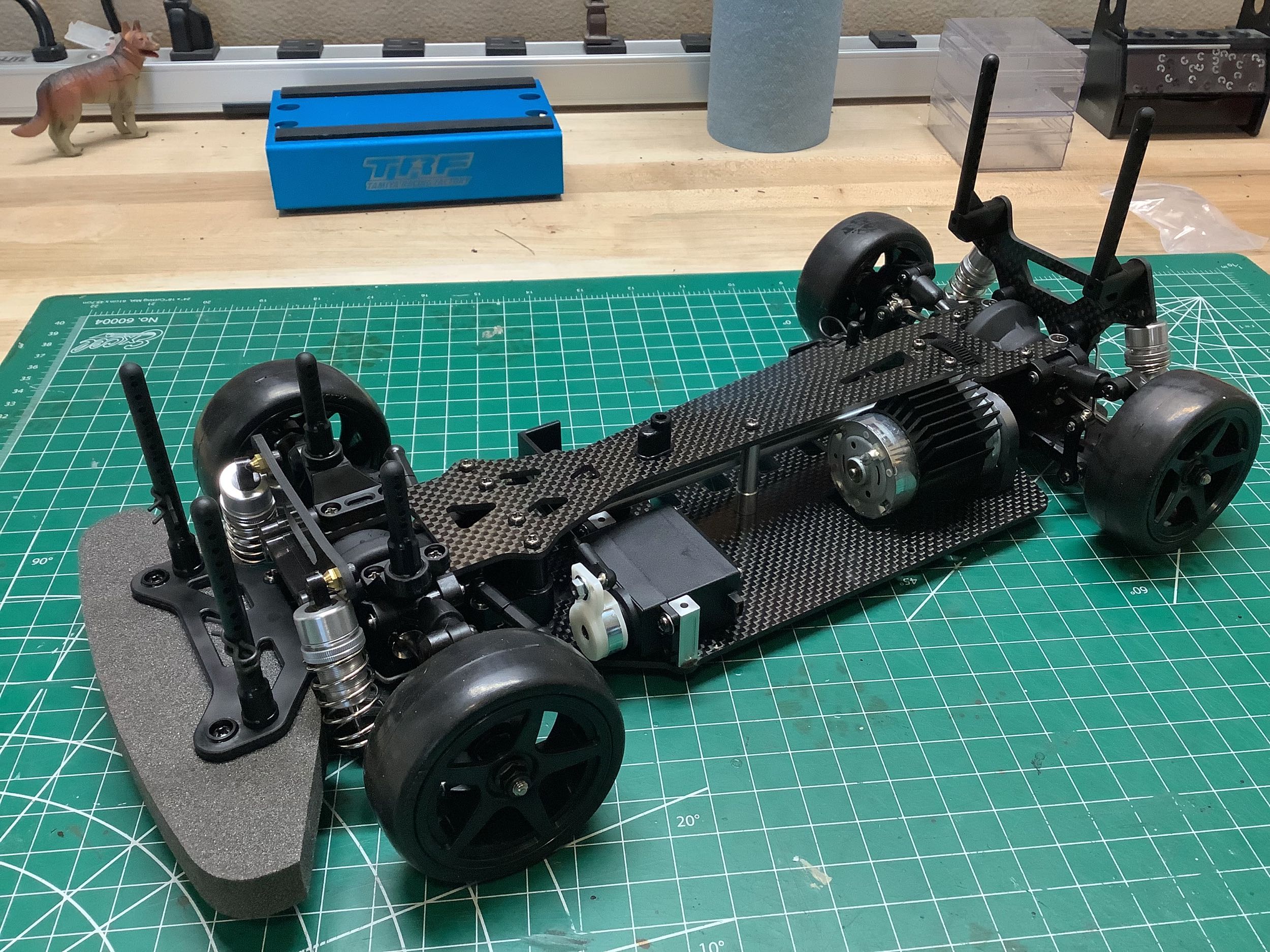
Step 32 installs the carbon upper deck using 16 screws! One of
those attaches the antenna support, but the others all connect to the
chassis. The most forward and most aft screw pairs are countersunk
and install with countersunk washers for extra footprint. All of
this makes for a very stiff chassis. The upper deck also caps the
steering posts holding the cranks in place.
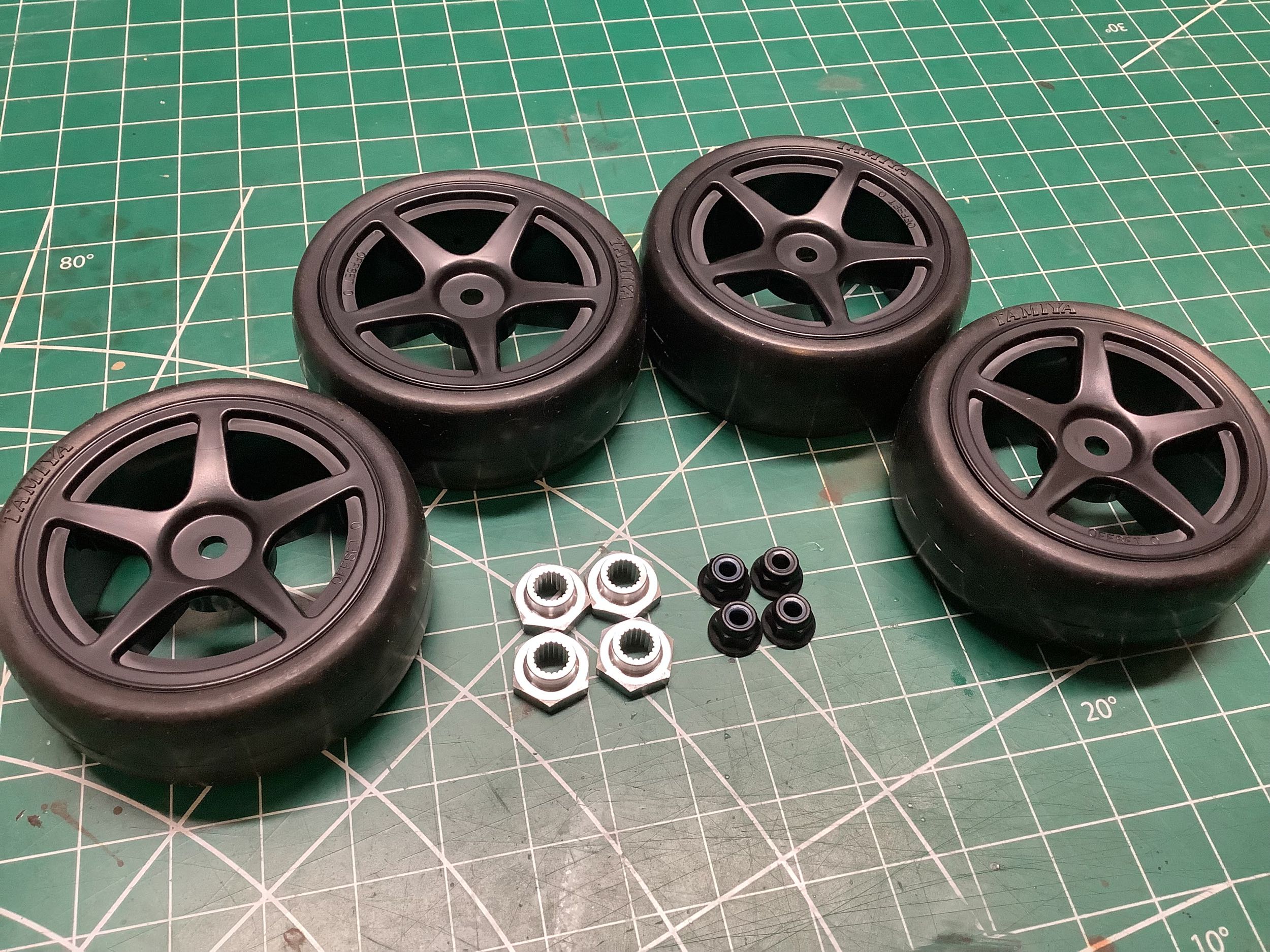
This chassis kit comes with wheels and tires. I'm pleased to
see spoked wheels here instead of boring dish wheels. These are
not the standard Tamiya tires either, and I'd have to say they are the
stickiest Tamiya tires I've ever seen. The spare part (9805677) is
just called "tires" so does not indicate how special they are.
They were included with the TB Evo and the TA-04 Pro. I wish they were
still made. There are also a set of closed cell foams
inside. You can see the unique splined 12mm wheel hubs on the
left. There are also unusual black wheel nuts. The picture
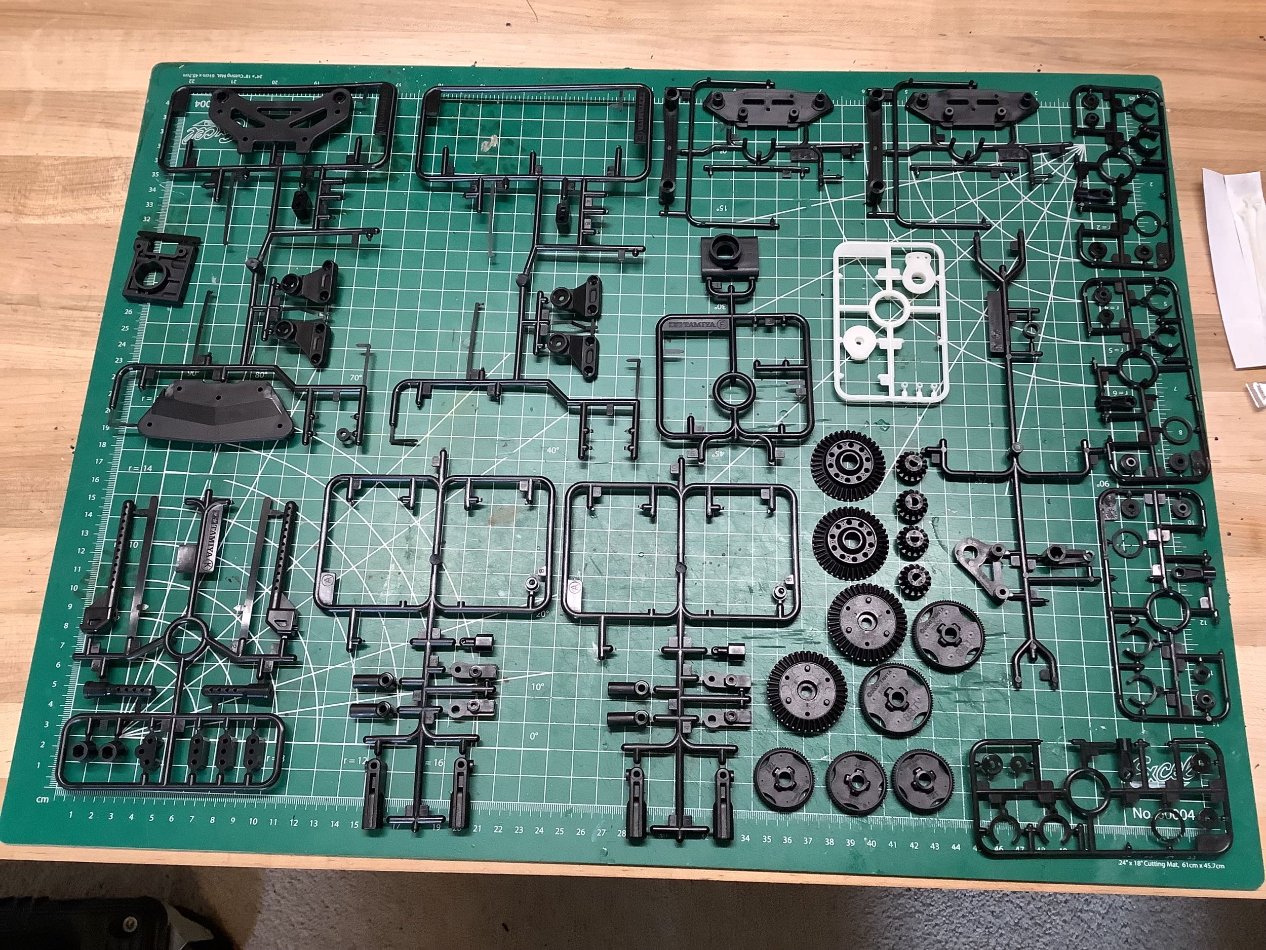
on the right shows the ridiculous number of
unused parts that come with this model. Some of these are spares
such as 2 extra front and rear differential ring gears, 4 extra
differential pinion gears, and 2 extra spur gears. There are also 3
copies of optional 72T spur gears. Most of the other parts are
just not used in this design even though they are present on the sprues.