1st
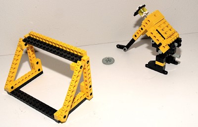
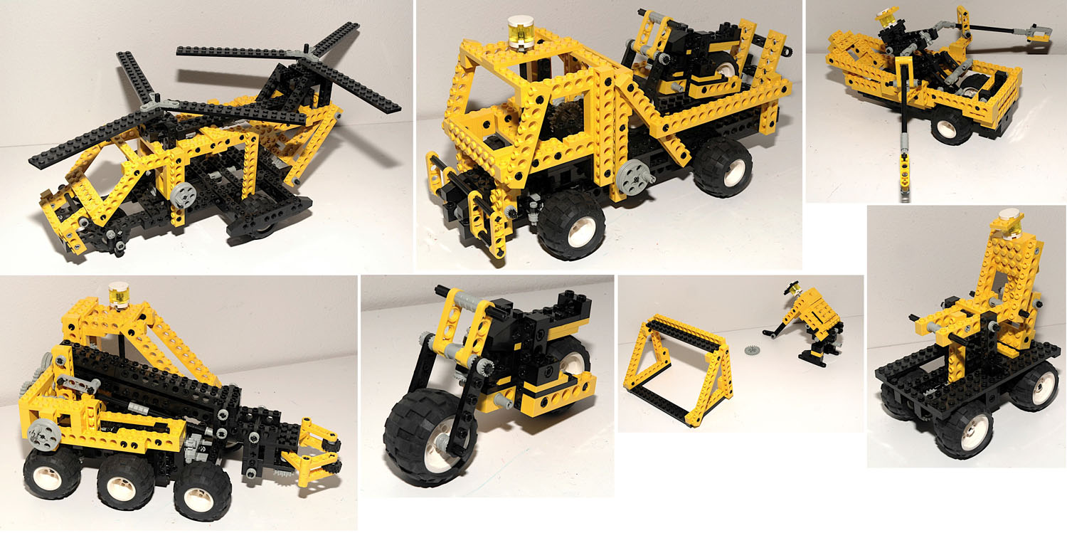
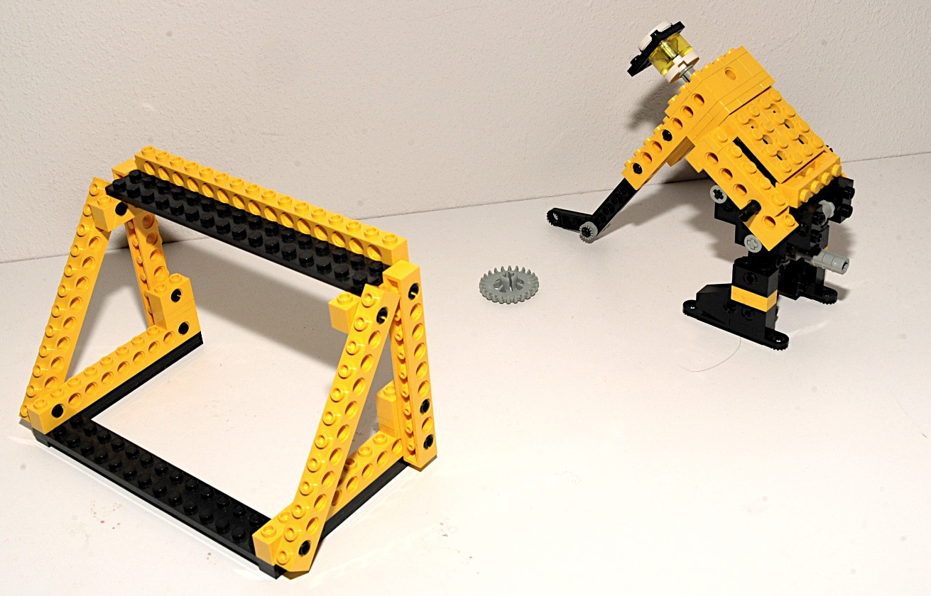
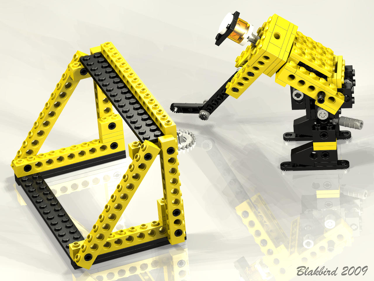
Model: Hockey Game
|
This
seems
to be a hockey player taking a slap shot at the goal. A
lever coming out of his backside rotates the whole upper body and
allows the stick to hit the puck, which is actually a 24 tooth crown
gear.
He's actually a pretty good shot!
|
Click
to download the LDraw
file of this model.
Model by Benjamin Wendl
Click for an animation of
the
slap shot.
|
2nd
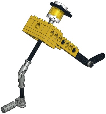
Model: Handcar
|
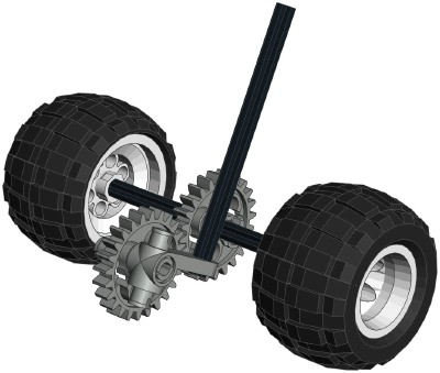
Here
we
have a handcar such as you might see used by someone maintaining
railroad tracks. Movement of the front wheels turns a gear with
an offset axle which oscillates a vertical link. This link is
attached to the handle and causes it to pump up and down. Since
the "driver" is also attached to the handle and is hinged at the waist,
he follows along.
|

Click
to download the LDraw
file of this model.
Model by Benjamin Wendl

Click for an animation of
the handcar in motion.
|
3rd
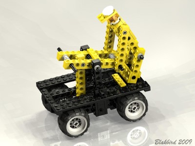
Model: Rowboat
|
Now
here is something which never appeared in Technic before or since, a
rowboat! The motion of this oarsman is excellent.
The partially hidden rear wheels turn a gear with an offset steering
arm which oscillates a link. This link
is attached to the pelvis of the oarsman. His feet are pinned to
the boat, as are his hips. As the link oscillates, his body
position changes. The oars attached to his hands pass through oar
locks pinned to the boat. The animation shows all of this motion
very clearly.
|
 Click
Click
to download the LDraw
file of this model.
Model by Benjamin Wendl
|
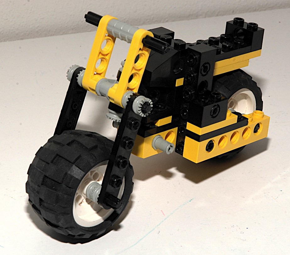
4th
Model: Motorcycle
|
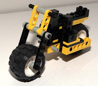
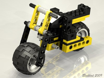
This
little
motorcycle is clearly the weakest model of the set. It
doesn't really do anything other than turn the handlebars. No
animation necessary; use your imagination.
It could be argued that this is really a part of the next model since
it can be loaded in the back of the truck.
|
Click
to download the LDraw
file of this model.
Model by Benjamin Wendl
|
5th
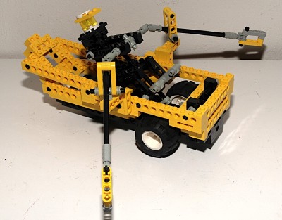
Model: Flatbed Truck
|
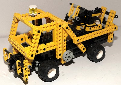
This
truck
is quite sizable and full featured with steering, an adjustable
ramp, and a tilting cab. The flatbed in back fits the motorcycle
quite nicely.
|
Click
to download the LDraw
file of this model.
Model by Benjamin Wendl
|
|
Steering
The front wheels can be steered using an overhead "hand of god"
wheel.
The
wheel drives set of 14 tooth bevel gears attached to a pinion.
The pinion drives the
steering rack. The
steering mechanism itself uses
control arms and toothed links.
The vertical axle actually disengages the bevel gears when the cab is
tilted forward.
It is unusual that this model has the steering arms facing forward
instead of backward like is usually seen.
|

Click for an animation of
the steering in motion.
|
|
Ramp
The ramp is driven by a crank on the left side. The crank turns a
worm gear which drives a 24 tooth crown. A universal joint moves the
axle up by one brick height, then a pair of bevel gears end the gear
train. The final axle uses a pair of pole reverser handles to
actually lift the ramp.
Because the mechanism uses a worm gear, it cannot be backdriven
(because the axial friction is higher than the backdriving torque due
to the screw pitch angle). This helps keep the ramp up when
in transit.
|
Click for an animation of
the ramp in motion.
|
|
Cab Tilt
The cab tilts forward via a crank on the right side. The crank
drives a pair of 14 tooth bevel gears which drive a worm. The
worm drives a 24 tooth spur gear attached to a pair of liftarms which
pivot the cab.
|


Click for an animation of
the cab tilting.
|
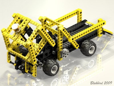
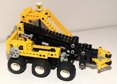
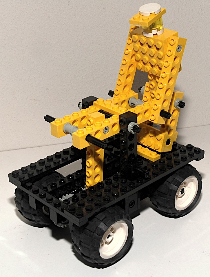
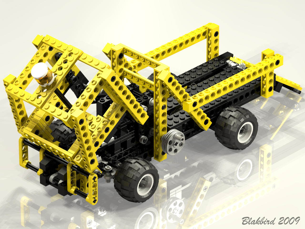
| 6th
Model: Loader |
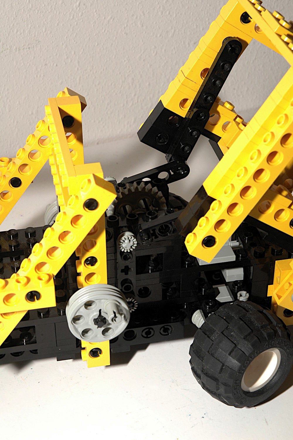
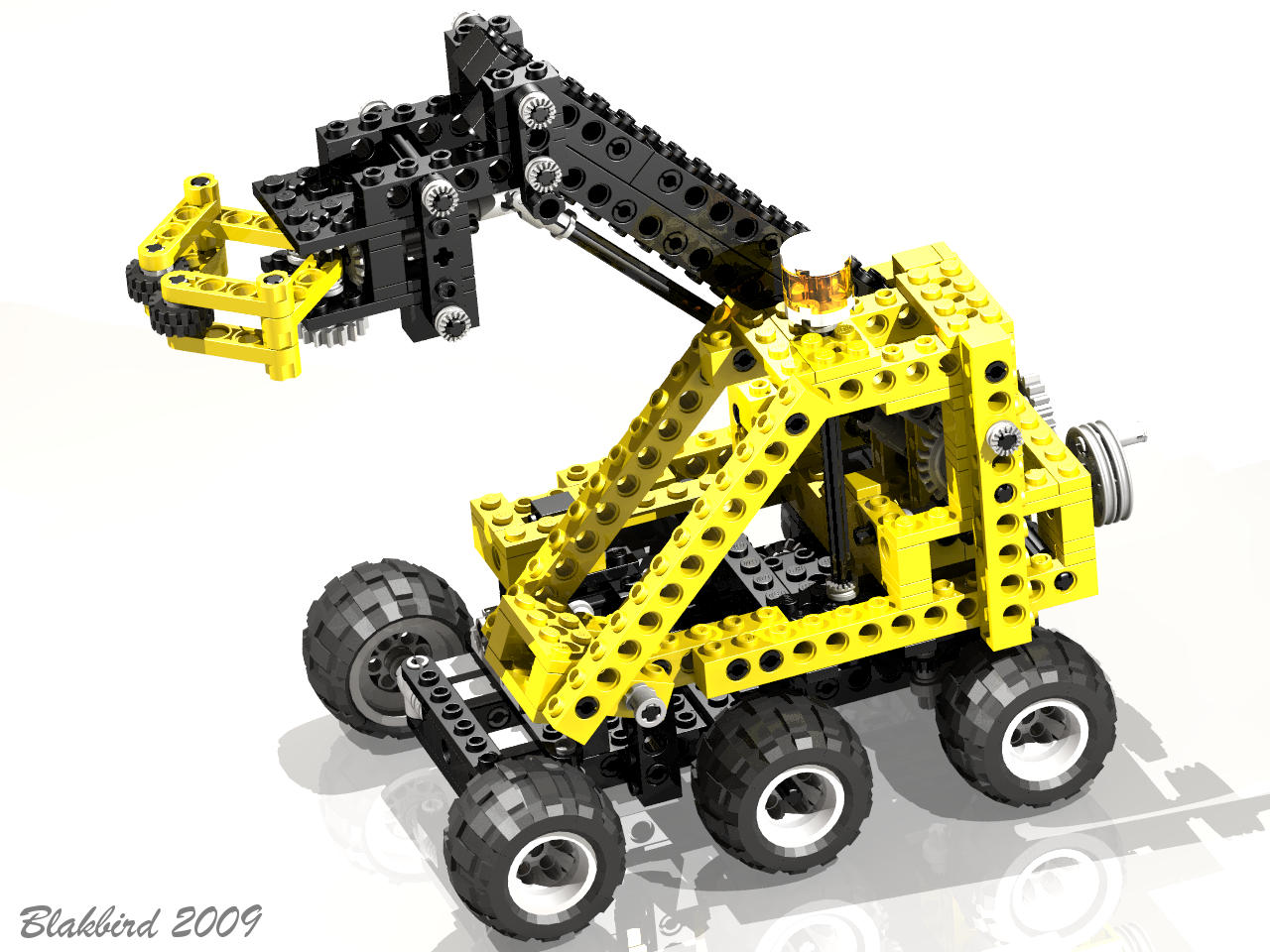
This
interesting
model is something like a log loader, although the vertical
claw indicates something more like the machines which cut down
trees. In any case, it's pretty cool and has many features
including 4 wheel steering, a lifting boom, and a working claw.
|

Click
to download the LDraw
file of this model.
Model by Benjamin Wendl
|
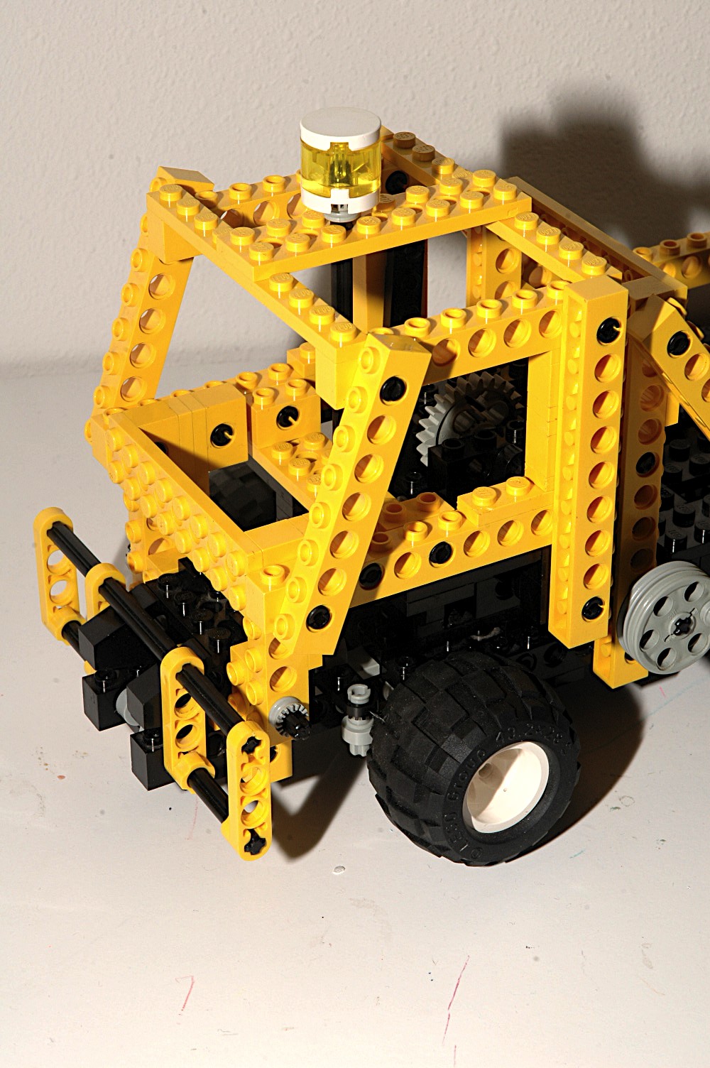
|
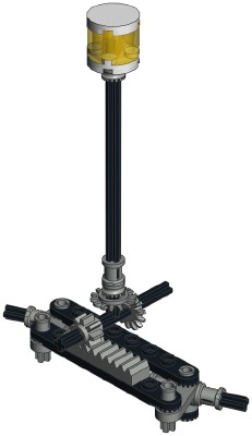
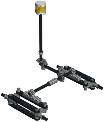
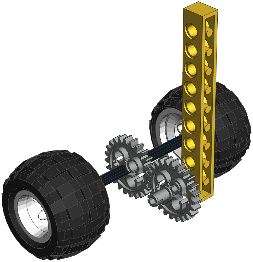
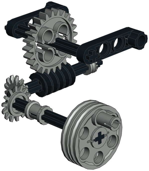
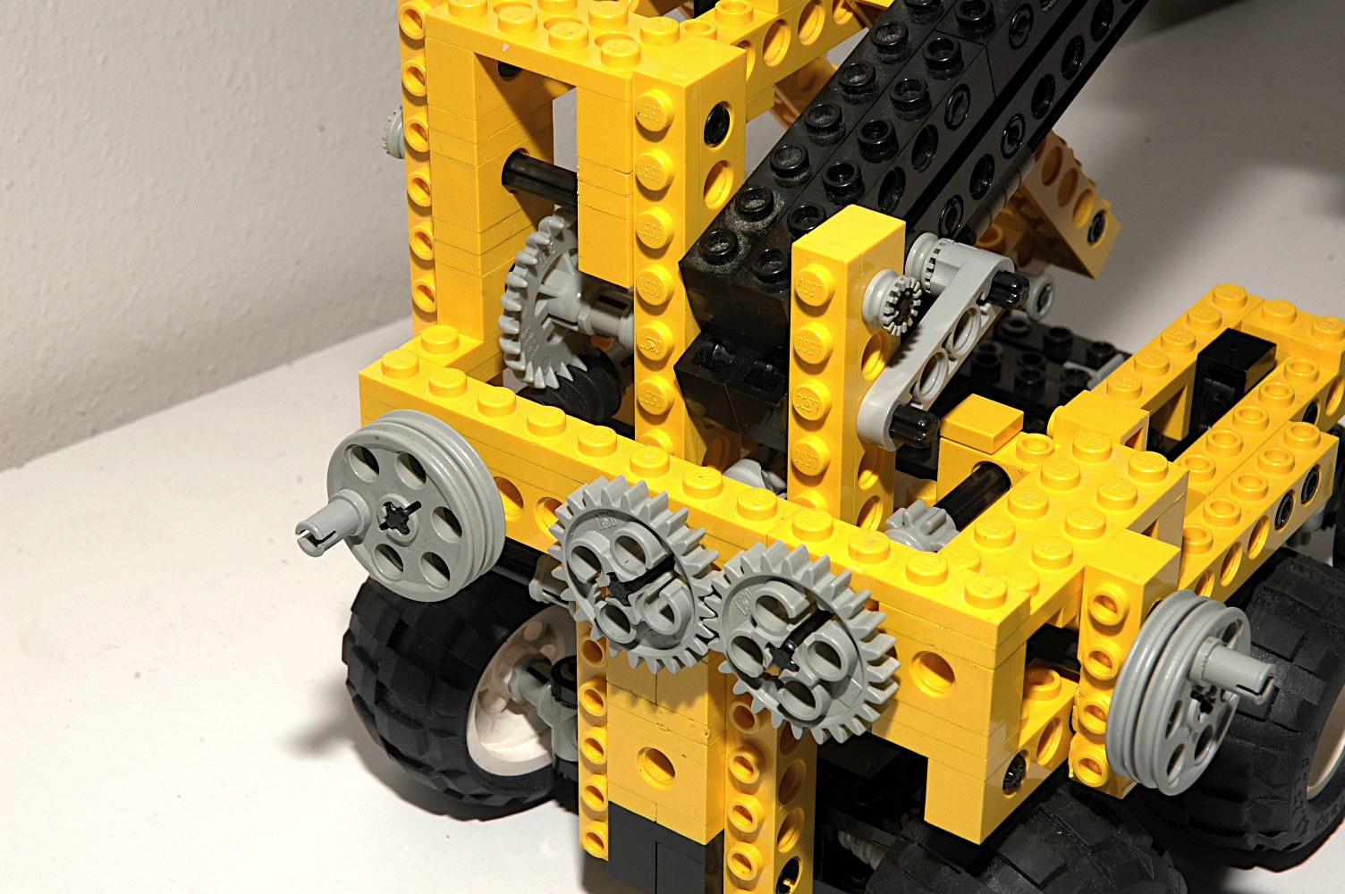
Steering
The front and rear wheels can be steered using an overhead "hand of
god" control which drives an axle connected to a pair of 14 tooth bevel
gears. Another set of bevel gears lead to a final axle which runs
to both the forward and rear gear racks which drives them in opposite
directions at the same ratio.
The steering mechanism itself uses the control arms and toothed links
as shown in the computer image.
|
Click for an animation of
the steering in motion.
|
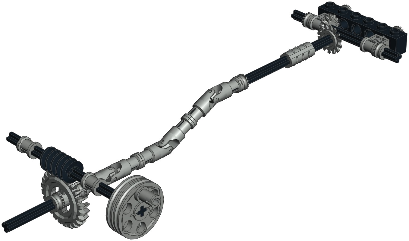
|
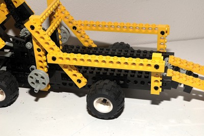
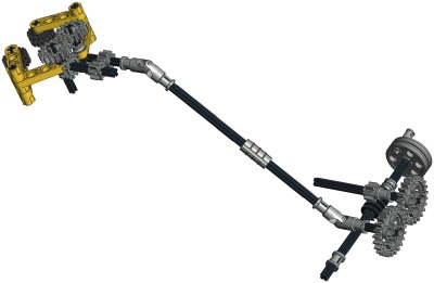
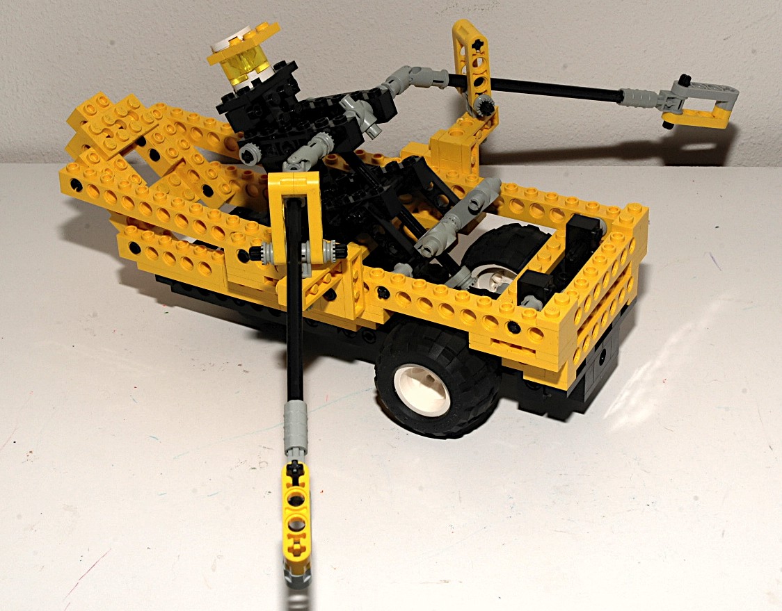
Boom Lift
The boom luffs via a crank on the back. This crank turns a worm
gear which drives a 24 tooth crown. A pair of liftarms connect to
the boom.
Because the mechanism uses a worm gear, it cannot be backdriven
(because the axial friction is higher than the backdriving torque due
to the screw pitch angle). This helps keep the boom up so
it does not fall under its own weight.
The boom utilizes a 4 bar linkage to keep the end claw parallel to the
ground as the main boom angle changes.
|


Click for an animation of
the boom lifting.
|
|
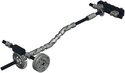
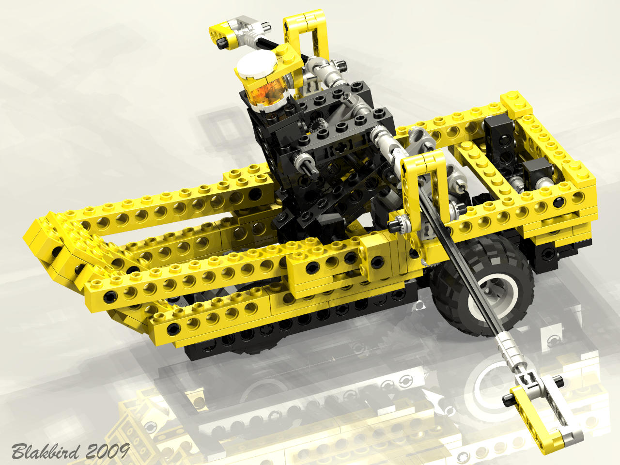
Grasping Claw
The claw at the end of the boom opens and closes via a crank on the
right side. The crank turns a worm gear which drives an 8 tooth
pinion. Next come a pair of 24 tooth spurs. A pair of
u-joints allow the next axle to pass up the length of the boom and
still operate as the boom angle changes. At the end of the boom
are a set of 8 tooth pinions which feed a set of 14 tooth bevel
gears. Finally the two claws are linked together with a pair of
16 tooth spur gears which allows them to move in opposite directions.
Despite all the gears in this complex system, only one of them alters
the gear ratio and that is the worm set. Final ratio is therefore
8:1.
|
Click for an animation of
the claw in motion.
|
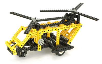
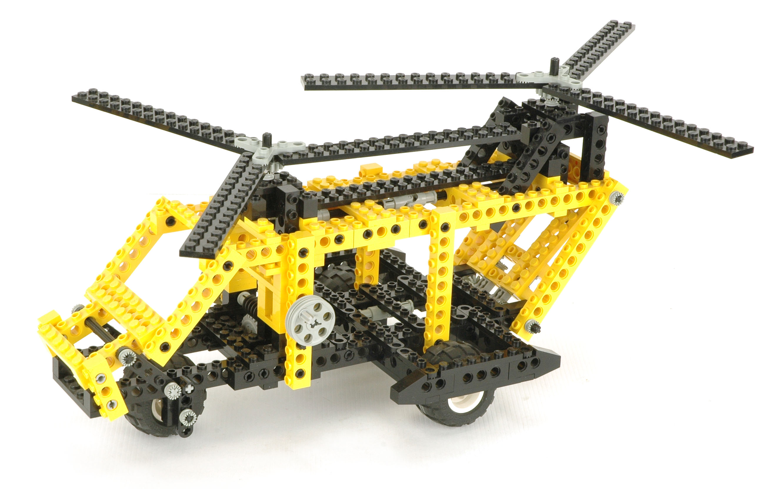
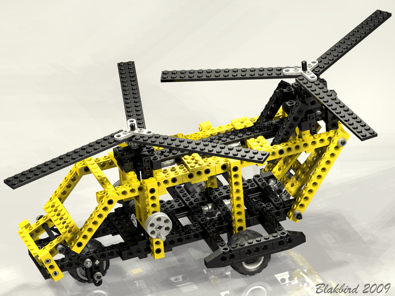
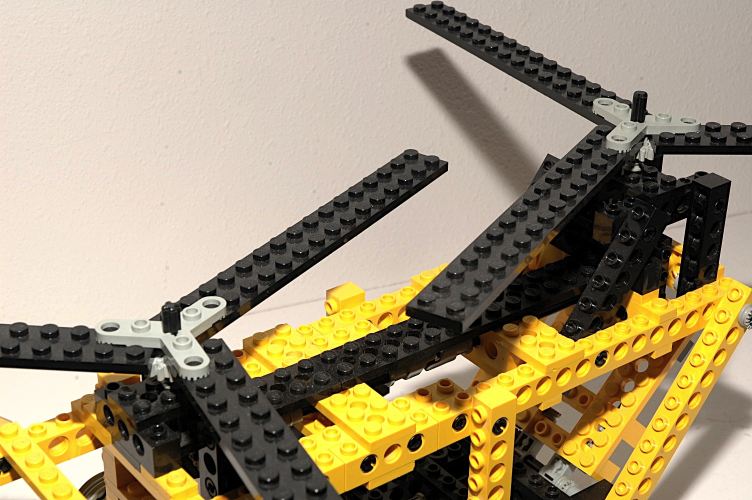
| 7th
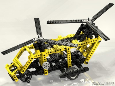
Model: Helicopter |
This
tandem
rotor helicopter resembles a CH-47 Chinook. Though it is
mostly empty space, it is one of my favorite Technic helicopters as it
captures the look and feel very accurately.
|
Click
to download the LDraw
file of this model.
Model by Benjamin Wendl
|
|
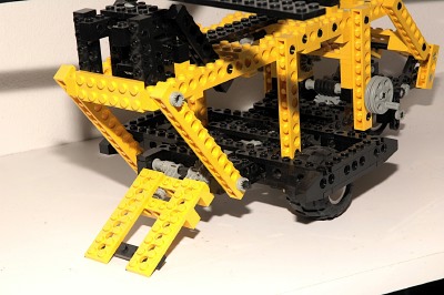
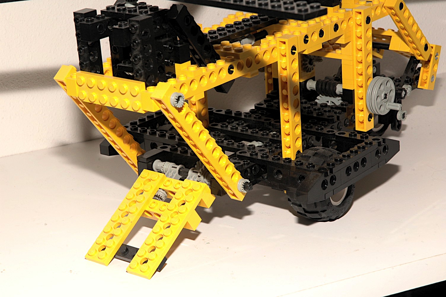
Loading Ramp
The ramp is driven by a crank on the right side. The crank turns
a worm
gear which drives a 24 tooth crown. Next a pair of bevel gears end the
gear train.
The final axle uses a pair of pole reverser handles to actually lift
the ramp.
Because the mechanism uses a worm gear, it cannot be backdriven
(because the axial friction is higher than the backdriving torque due
to the screw pitch angle). This helps keep the ramp up when
in
transit. |
Click for an animation of
the ramp in motion.
|
|
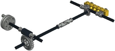
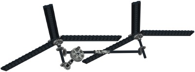
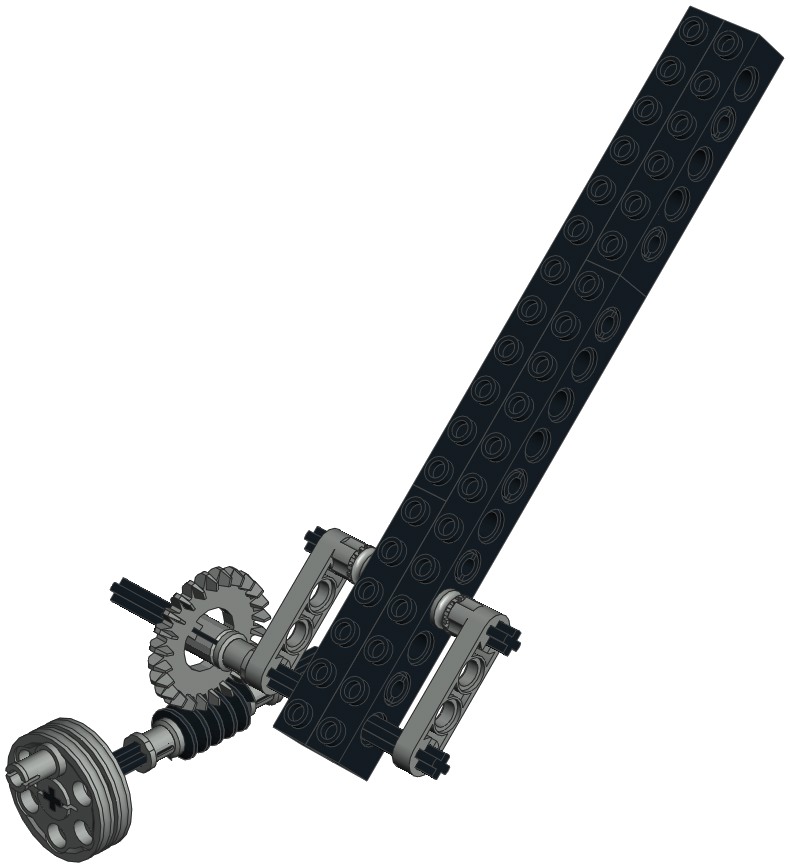
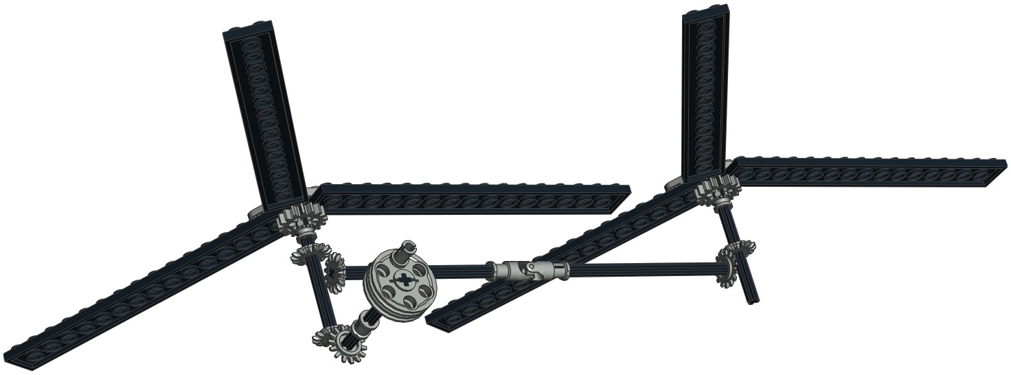
Rotors
The tandem rotors are driven by a crank on the left side. This
crank drives a set of bevel gears. The first of these goes
directly up to the forward rotor. Another set of 14 tooth bevel
gears send the torque aft through yet a 3rd set and finally into the
aft rotor.
The rotors are counter rotating. Because they are geared
together, they can be clocked to not hit each other.
Additionally, the rotors are in different planes (aft is higher), so
they could not come into contact anyway.
|

Click for an animation of
the rotors in motion.
|


