1st
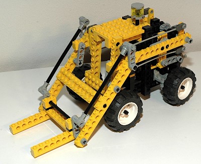
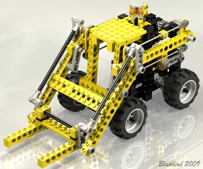
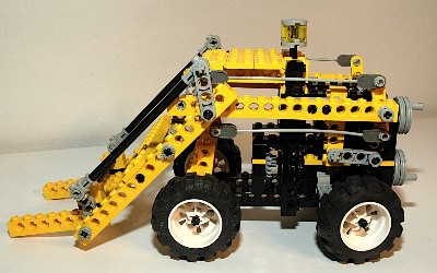
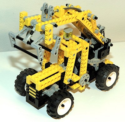
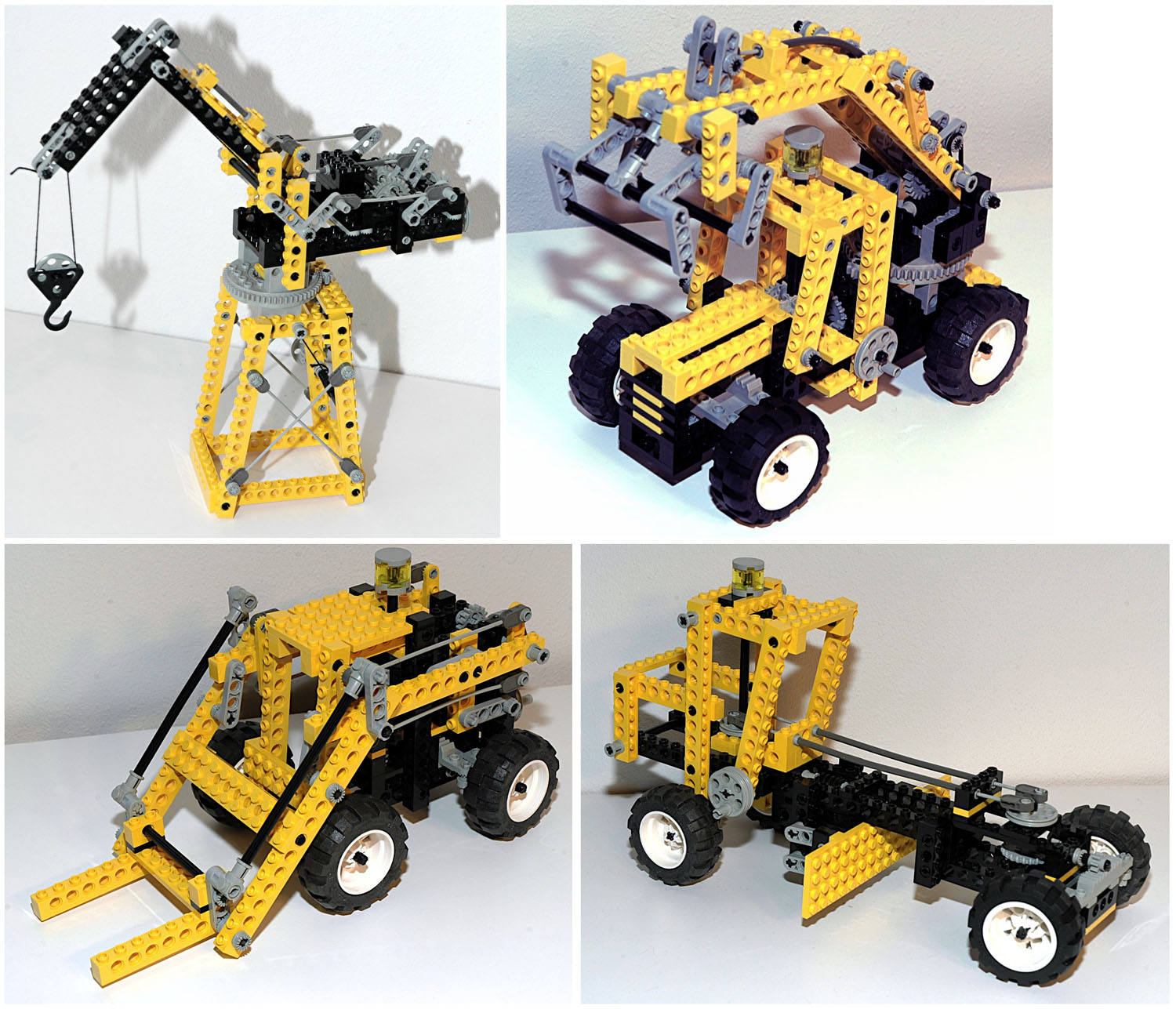
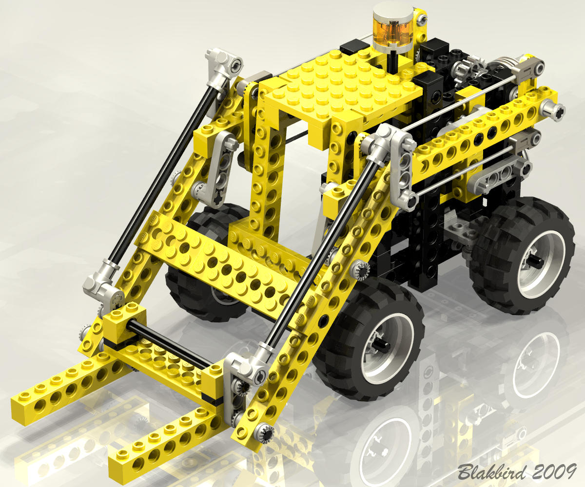
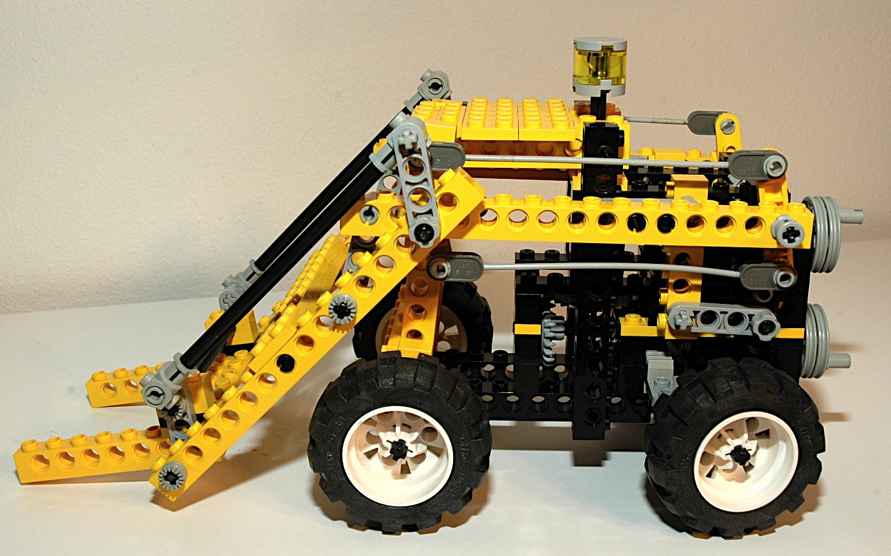
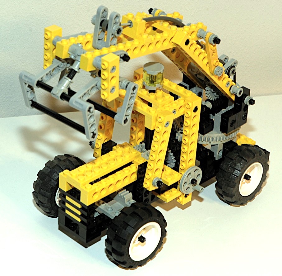
Model: Forklift
|
This
forklift
is an excellent model. The fork boom does not lift
vertically, but pivots from the rear on a four bar linkage like a
skid-steer loader, but in this case the model has rear wheel
steering. It uses the flex system to control the tilt of
the forks.
|
Click
to download the LDraw
file of this model.
Model by Benjamin Wendl
|
|
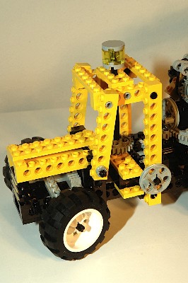
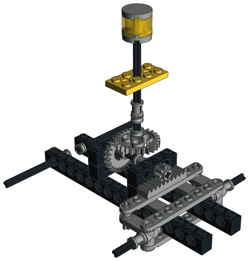
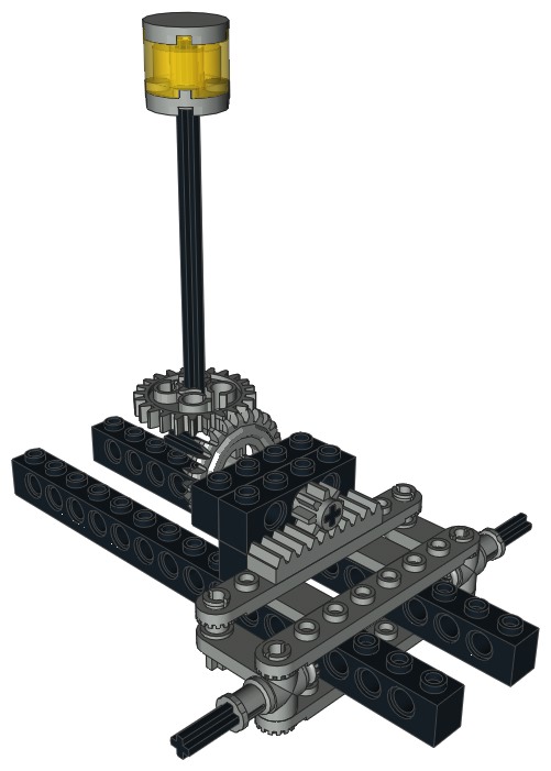
Steering
The front wheels can be steered using an overhead "hand of god"
wheel. The
wheel drives a pair of 24 tooth gears which drive a
pinion. The pinion drives the steering rack. The
steering mechanism itself uses
steering arms and toothed links. |
|
|
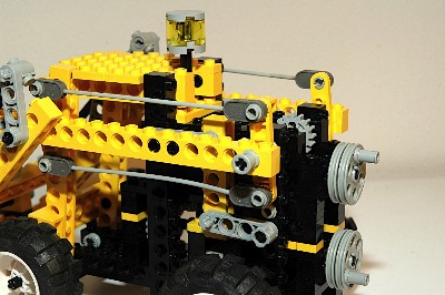
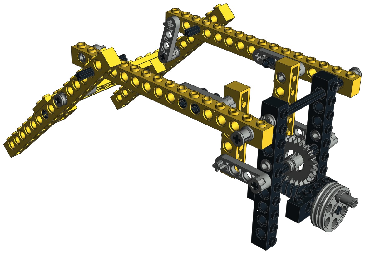
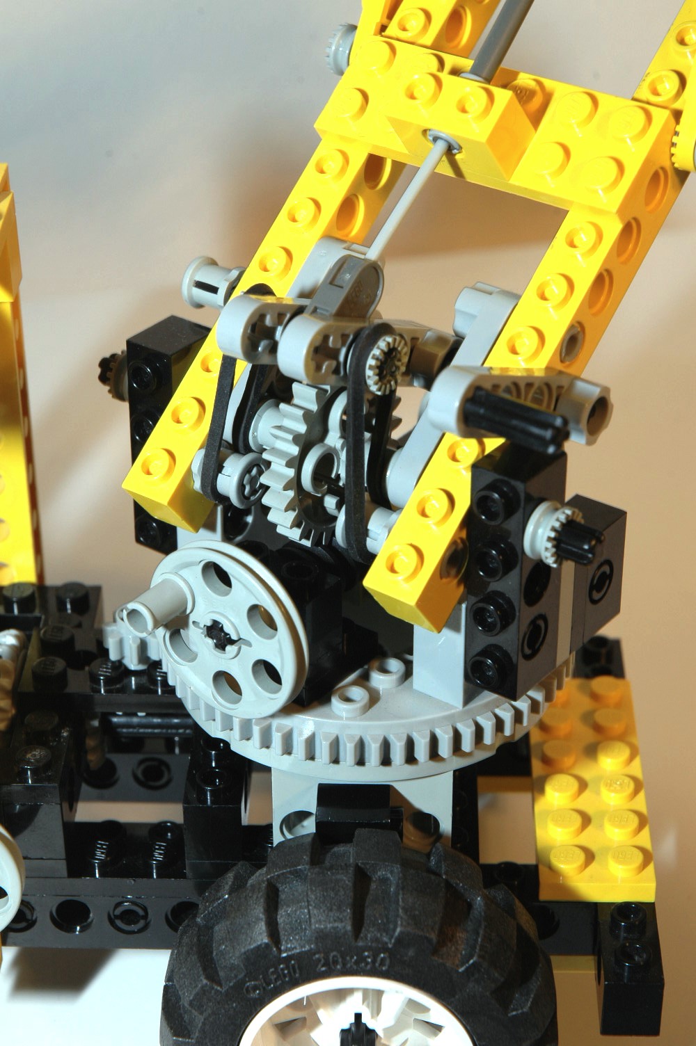
Forks
The forks are raised by a crank on the back via a 4 bar linkage.
The crank turns a worm gear which mates with a 24 tooth crown.
The crown gear drives an axle which rotates a pair of liftarms.
These liftarms push up on a vertical beam which then lift the support
arms.
The support arms tilt down at about a 45 degree angle and are locked in
position with a pair of liftarms. The angle cannot be
changed. This means that the forks tend to change angle (tip
back) as they are raised.
|
|
|
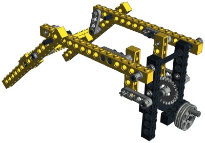
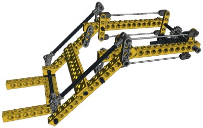
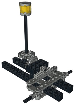
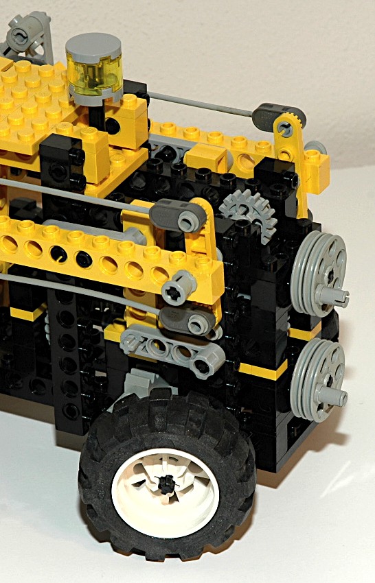
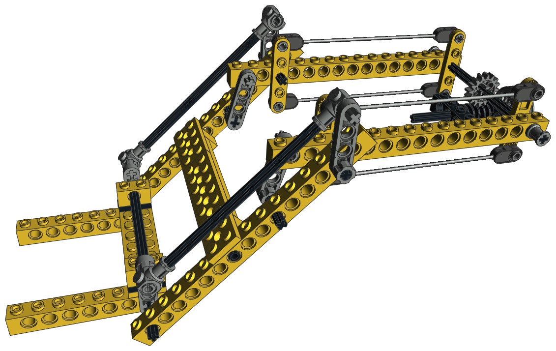
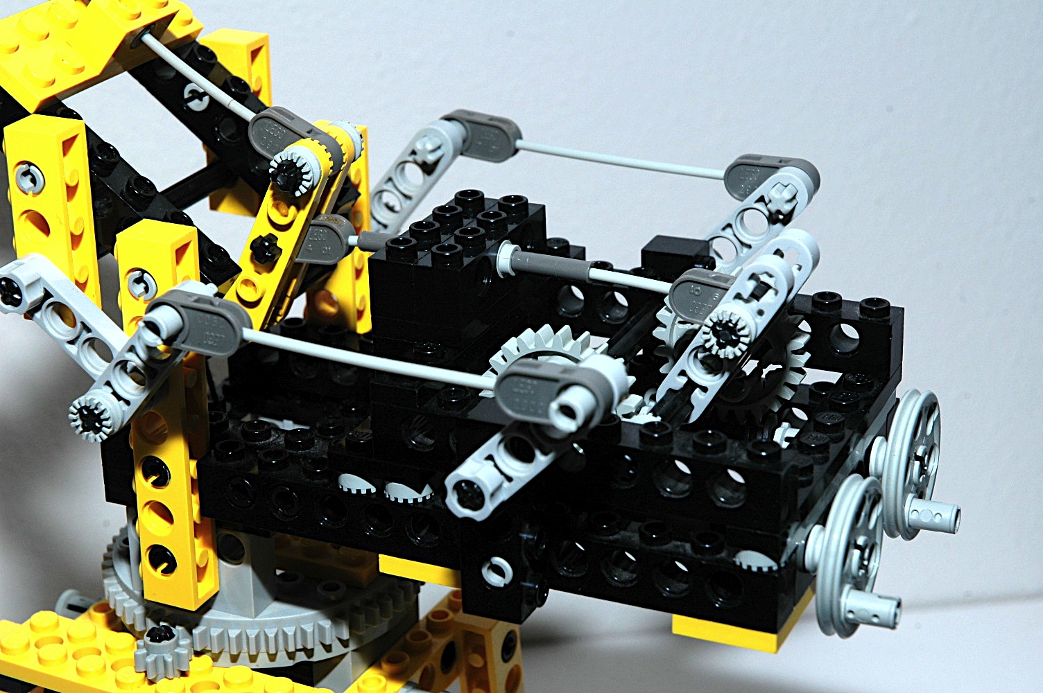
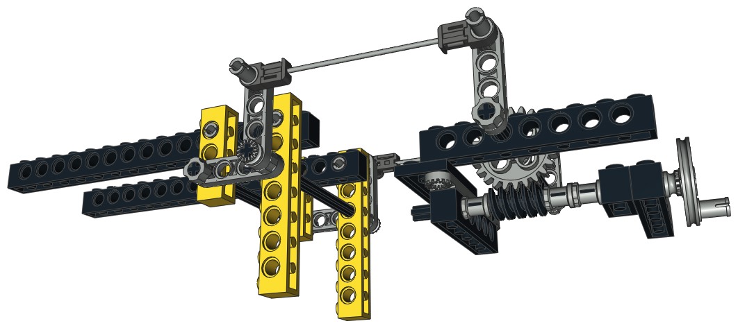
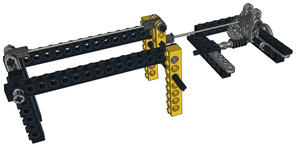
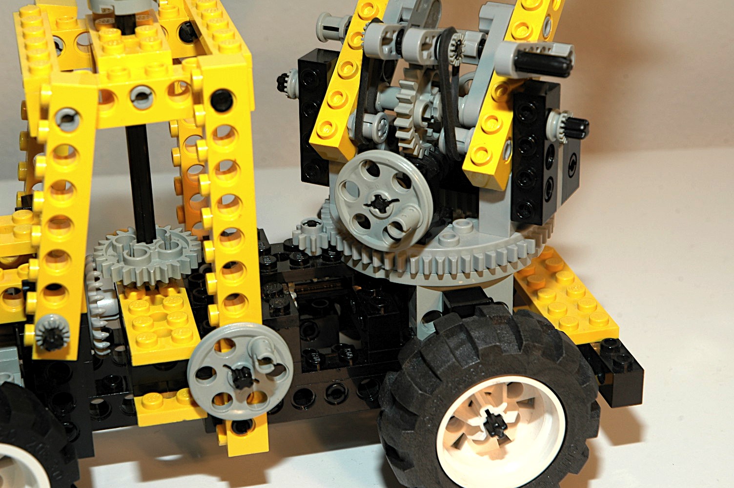
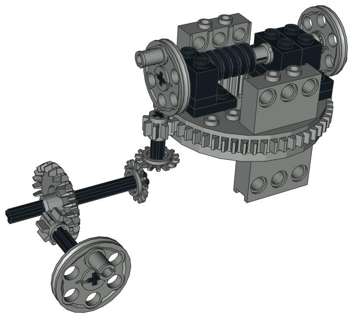
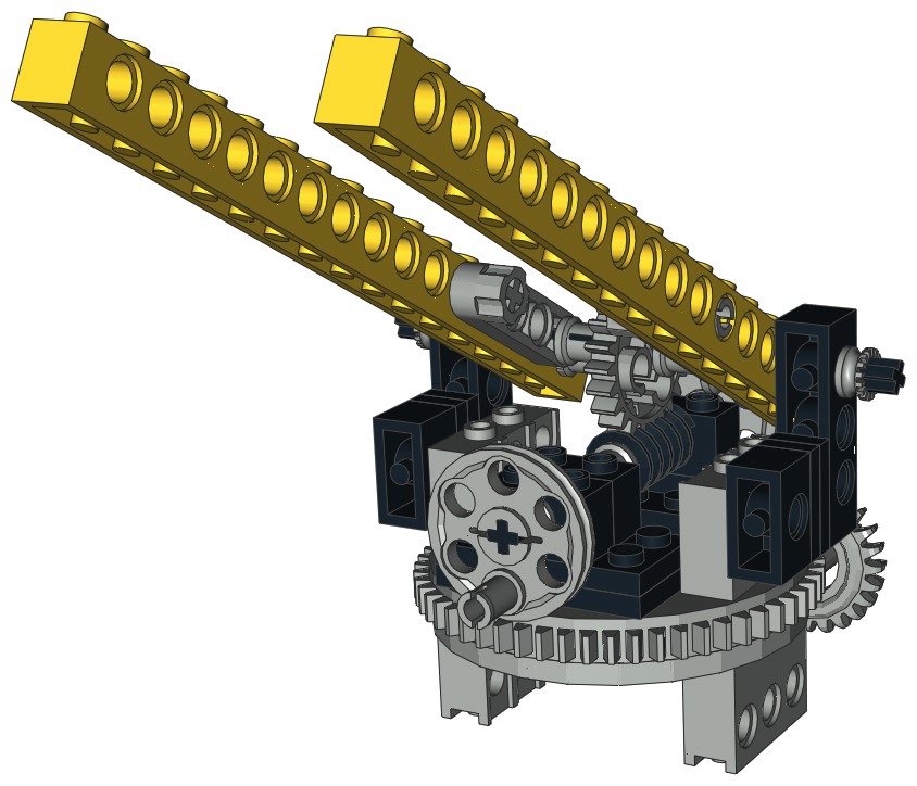
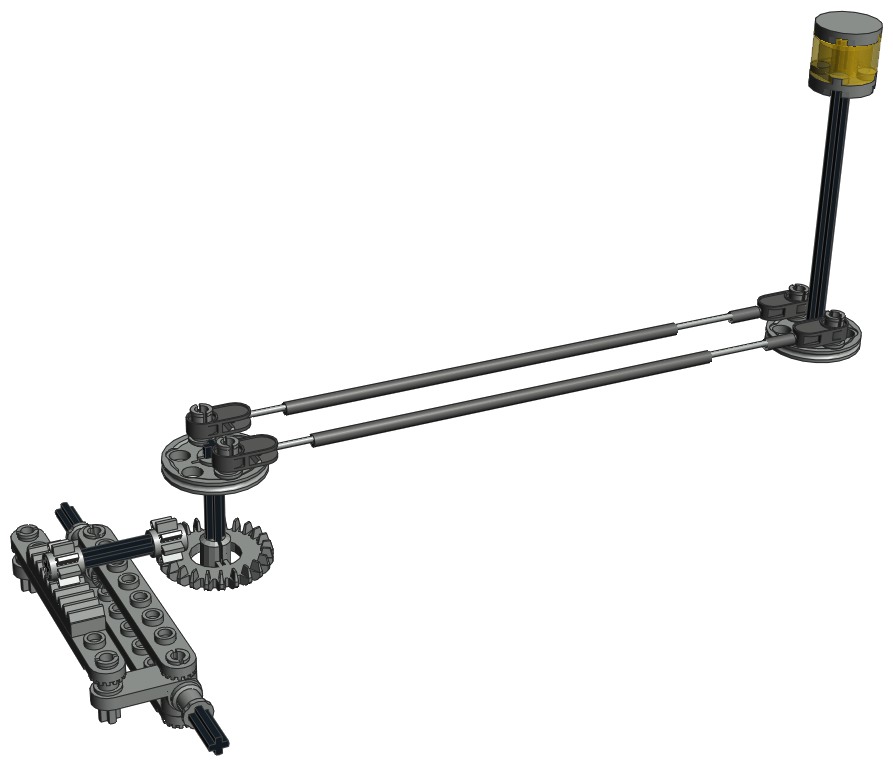
Fork Tilting
The forks can be tilted using a crank on the rear of the vehicle.
The crank drives a worm which mates with a 16 tooth spur gear.
This axle then rotates a pair of 2-blade rotors. The rotors are
locked to the rotation of the axle at their center point. On
either end of the rotors are attachments to flex cables. Because
both arms of the rotor are the same length, the upper and lower cables
move the same amount when rotated (see computer image). This type
of system is often called pull-pull. Even though these cables can
support some compression, there is no need for compression because
either rotation direction can be carried in tension.
Consequently, this would work even if just string was used. Look
at the Curtiss Jenny for a great example!
Through the cables, the rotation of the rotors is matched at the other
end with another pair of rotors. These turn a liftarm which
drives an axle as part of a 4 bar linkage. This could also have
been accomplished with another pull-pull cable system. The last
set of liftarms pivots the forks.
|
Click for an animation
of the forks tilting.
|
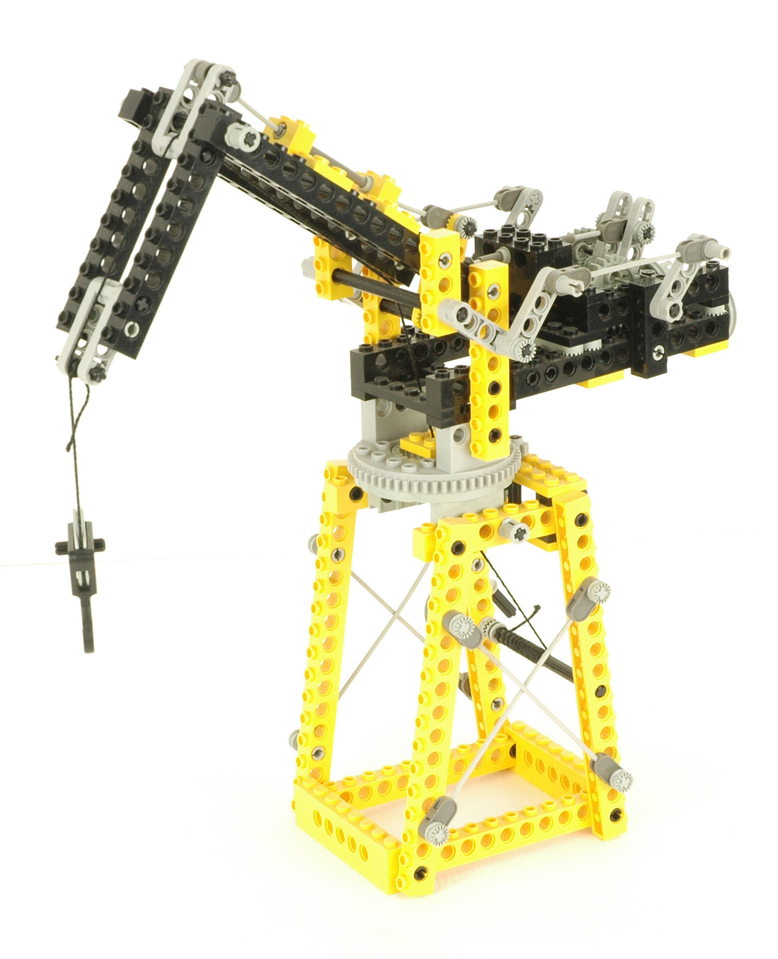
2nd
Model: Crane
|
This
is
one of the few stationary crane models in the Technic line. It
is quite functional and uses the flex system in great ways.
|


Click
to download the LDraw
file of this model.
Model by Benjamin Wendl
|
|
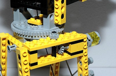
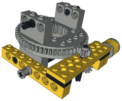
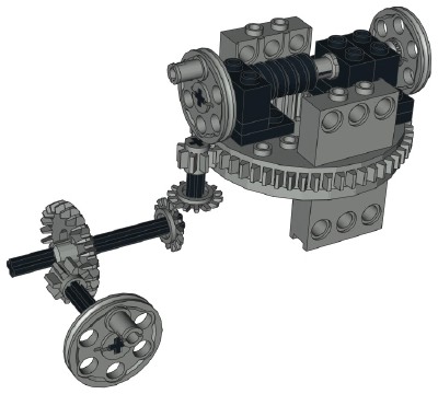
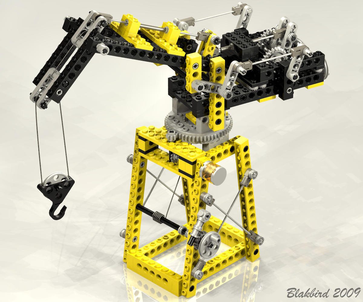
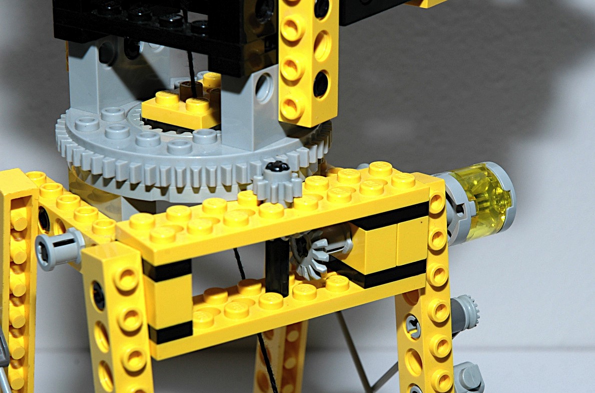
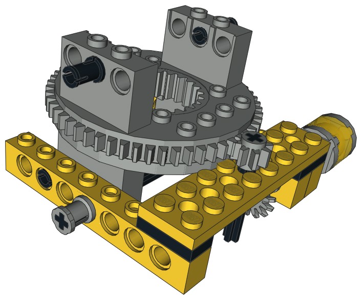
Slew
The upper superstructure can slew about the base truss using a geared
turntable. A small crank on the side turns a pair of 14 tooth
bevel gears. An 8 tooth gear then drives the turntable.
Since the outer ring gear on the turntable has 56 teeth, the gear ratio
is 7:1.
Note that the cable for the hoist passes through the center of the
turntable. This allows the top to rotate without pulling the
cable.
|
Click for an animation of
the crane
slewing.
|
|
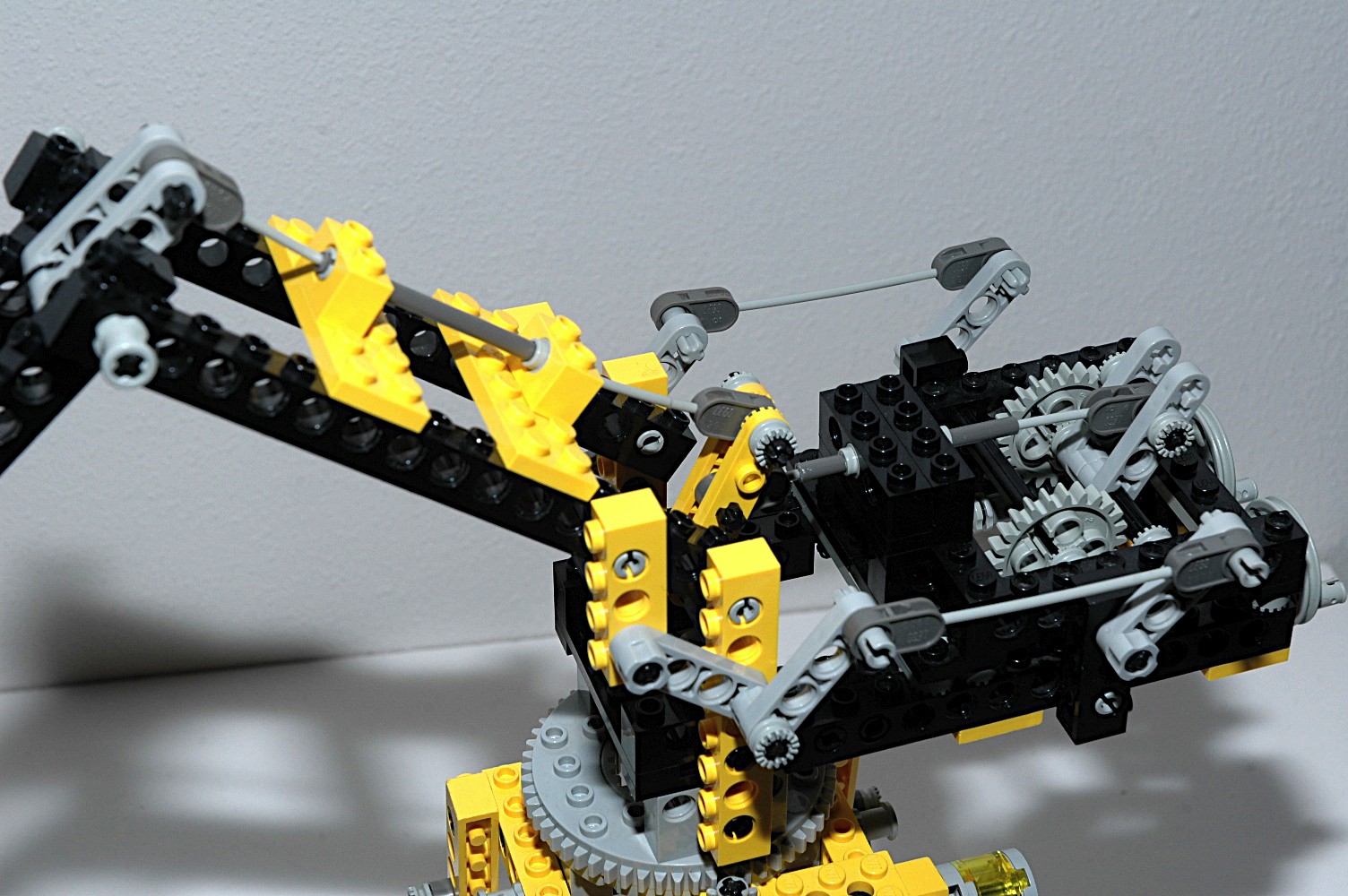
Luffing Boom
The main boom can be raised and lowered using a crank on the
back. The crank turns a worm gear which drives a 24 tooth spur
gear. The spur gear rotates a pair of liftarms. An attached
pair of flex cables attach to liftarms at the other end. These
liftarms rotate another set of linked liftarms which raise the boom.
Because of the offset weight of the boom, the flex cables are always in
tension.
|


|
|
Luffing Jib
The jib can be raised and lowered using a crank on the back. The
crank turns a worm gear which drives a 24 tooth spur gear. The
spur
gear rotates a pair of liftarms. An attached flex cable
attaches to 2 blade rotors at the other end. The liftarms pivot
at the bottom of the rotors, and the flex cable attaches to the
middle. Another flex cable attaches to the opposite end which
ends up amplifying the deflection. The second flex cable attaches
to a final set of liftarms which are locked to the jib.
Because of the offset weight of the jib, the flex cables are always in
tension.
These two flex cables are guided by sleeves which allow them to assue
curved shapes without catching on anything.
|
|
|
Hoist
The simple cable hoist is driven by a crank which uses an axle as a
cable drum. A 16 tooth spur gear is used as a ratchet to keep the
cable from unwinding under load.
|
|
3rd
Model: Log Loader
|
There
is
only one other log loader in Technic history, and it wouldn't come
until much later. For it's size, this model has a tremendous
number of features, and it even looks pretty good!
|
 Click
Click
to download the LDraw
file of this model.
Model by Benjamin Wendl
|
|
Steering
The front wheels can be steered using an overhead "hand of god"
wheel. The
wheel drives a pair of 24 tooth gears which drive a
pinion. The pinion drives the steering rack. The
steering mechanism itself uses
steering arms and toothed links. |
Click for an animation of the
steering in motion. |
|
Slewing Boom
The boom is supported by one of the new turntables. This is
only the second set to contain one after 8094.
A
crank on the left side drives a set of 8 and 24 tooth gears.
Torque then passes through a pair of 14 tooth bevel gears.
Finally, an 8 tooth pinion drives the outer ring gear of the turntable
which has 54 teeth. Final gear ratio is 21:1.
If slightly raised, the boom can rotate 360 degrees without hitting
anything.
|

Click
for an animation of the boom slewing.
|
|
Luffing Boom
The main boom can be raised using a pair of cranks on the
turntable. Both cranks turn the same axle which drives a worm
gear. The worm gear mates with a 24 tooth spur gear. The
spur gear axle passes through a pair of liftarms which locks them to
the axle. The other end of the liftarms is locked to the boom
beams with axle pins, so the boom rotates at the same rate as the 24
tooth gear.
Because of the 24:1 ratio, the crank can lift this large cantilevered
mass easily. The system
cannot be backdriven because the axial friction is higher than the
backdriving torque due to the screw pitch angle. |
|
|
Claw
The grasping claw on the end of the boom can be opened via a lever
arm. The claw is spring loaded to the closed position with a pair
of rubber bands near the lever. A flex cable attached to the
lever runs up to a pair of liftarms which rotate to drive the claw.
Keen eyed observers may note that the claw does not close
completely. This is due to the fact that my set appears to have
the wrong flex cable which is one unit longer than it should be.
|
|
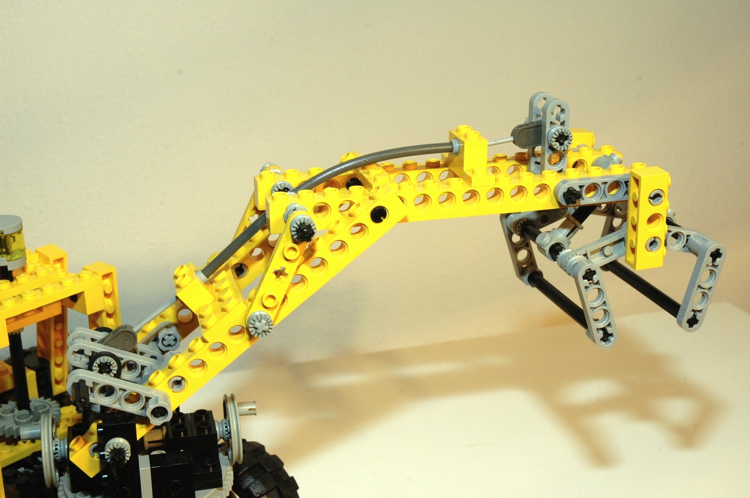
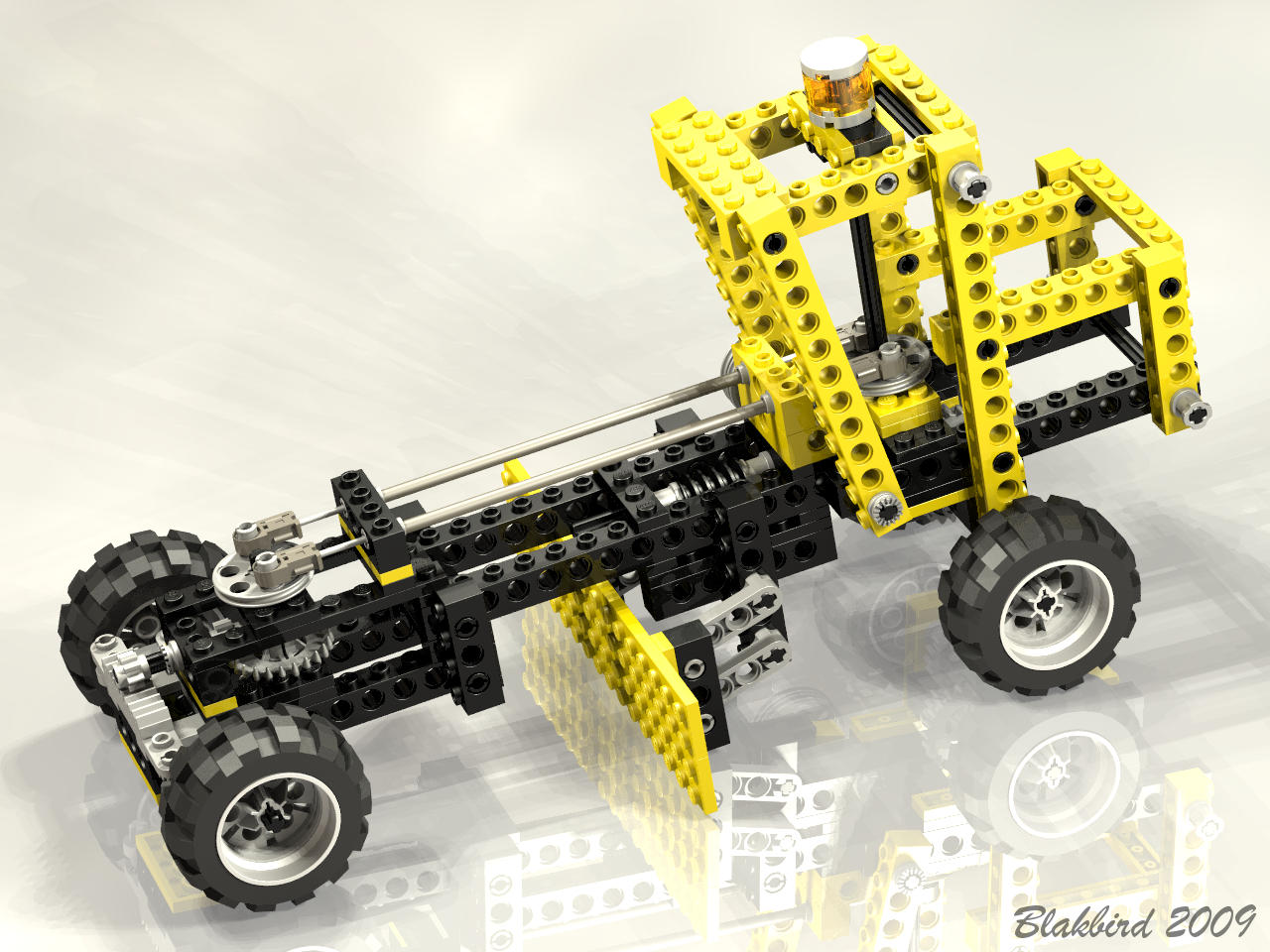
4th
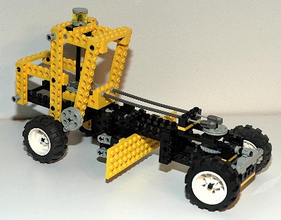
Model: Grader
|
This
is
the only LEGO® Technic road grader. This one is
rather simple since it lacks the dual rear axles and pendular front
axle of many real graders, but it is a fine model none the less.
|

Click
to download the LDraw
file of this model.
Model by Benjamin Wendl
|
|
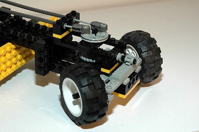
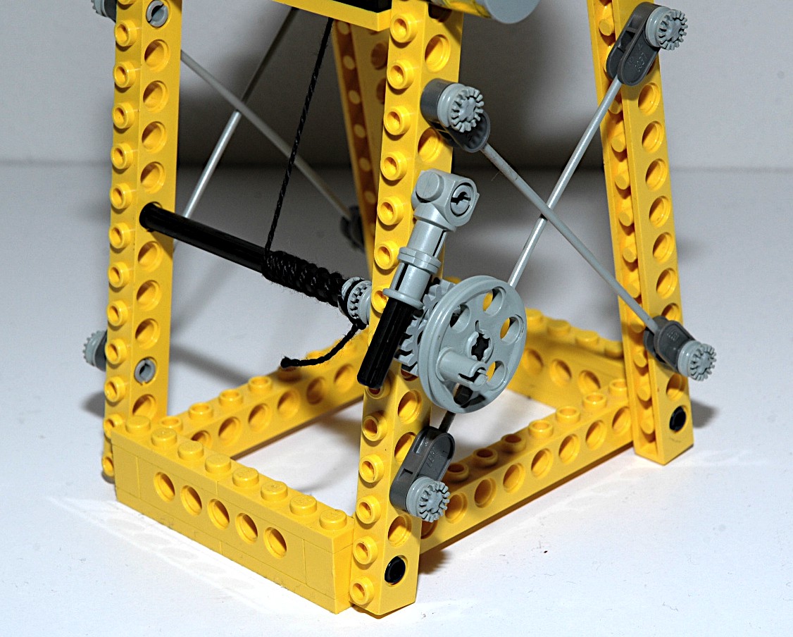
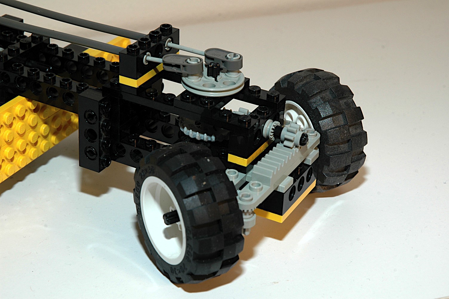
Steering
The front wheels can be steered using an overhead "hand of god"
wheel. The
wheel drives a pulley used as a crank arm. On either side of the
crank arm are long flex cables which run forward to a similar
attachment on the front of the vehicle. A set of 8 and 24 tooth
gears adjust the torque 90 degrees. The final axle drives an 8
tooth pinion. The pinion drives the steering rack. The
steering mechanism itself uses
steering arms and toothed links.
In this case, the same length flex cable is used on either side.
This type
of system is often called pull-pull. Even though these cables can
support some compression, there is no need for compression because
either rotation direction can be carried in tension.
Consequently, this would work even if just string was used.
|

Click for an animation of
the steering in motion.
|
|
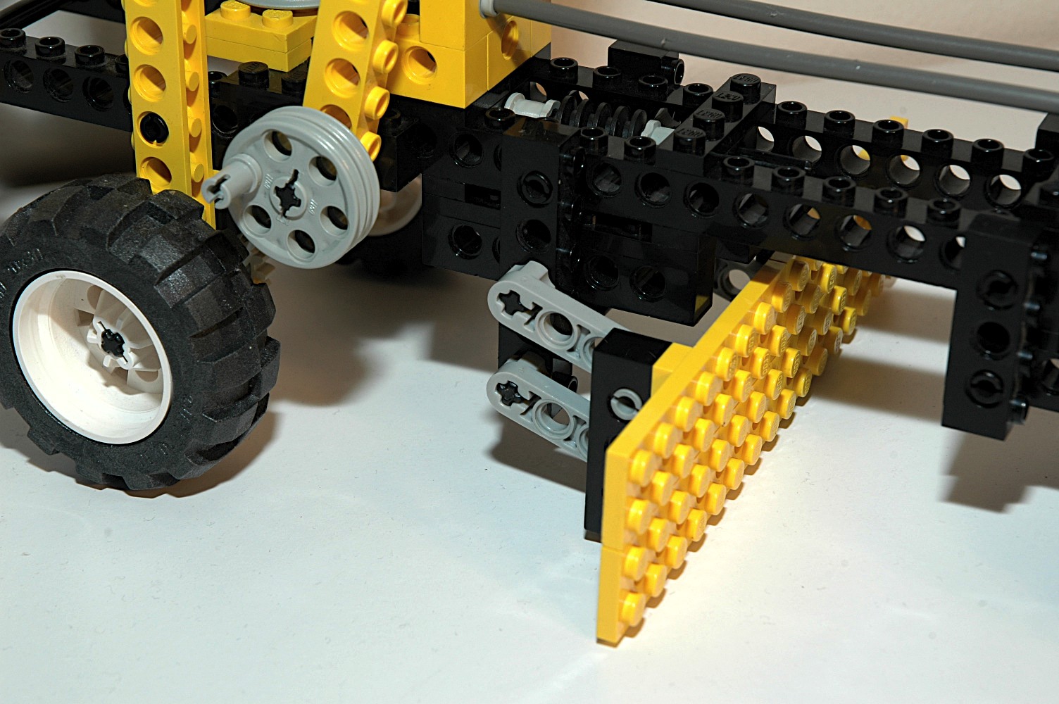
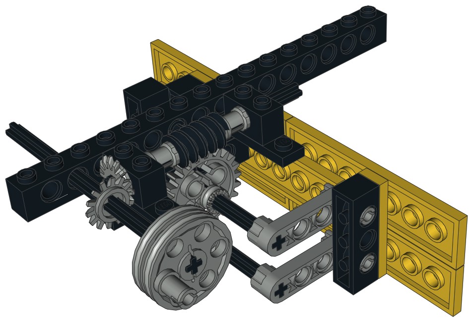
Grading Blade
The blade can be raised and lowered via a 4 bar linkage. A crank
is used to turn an axle which runs through a pair of 14 tooth bevel
gears. The bevel gear turns a worm which drives a 24 tooth spur
gear. This spur gear is attached to an axle which makes up one
axis of a 4 bar linkage. Four liftarms keep the blade parallel
which it lifts on a pair of 4L beams.
|


Click for an animation of
the blade in motion.
|


