1st
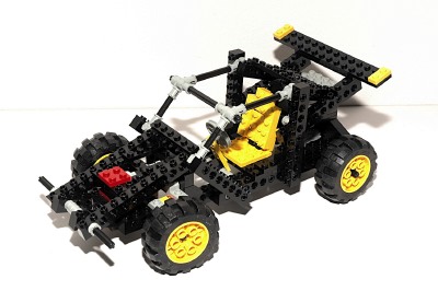
Model: R/C Car
|
|
Remote Control
This car was the first Technic set which featured any kind of remote
control other than the simple on/off in 8064.
The
remote
is a hand held device containing the battery box and a pair
of pole reversers. The left hand switch moves forward and back
and controls the drive wheels of the model. The right hand switch
moves side to side and controls the steering of the model.
A pair of wires, one for each motor, run from the controller to the
model. The wires are quite long and allow you to stand and drive
the model on the floor while following it.
For reasons outlined below, this is not a very controllable R/C car,
but it was an excellent first model and would be improved in various
ways in the future.
|

Click
to download the LDraw
file of this model.
Model by Benjamin Wendl
|
|
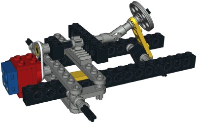
Steering
The front wheels can be steered using the remote. A micro motor
drives an axle through a belt and a pair of pulleys. The axle
drives a pinion which drives the steering rack. A u-joint
connects the driver's
wheel so it follows along as the wheels are turned.
The use of a belt allows the steering to contact its stop without
stalling the motor. The very slow rotation speed of the micro
motors allows for fairly precise steering control. However, there
is no servo so there is no position feedback. The steering is
also not spring loaded to center. This means that at the end of a
turn you have to manually recenter the wheels by reversing the
steering. This makes driving quite difficult and going straight
almost impossible.
|
Click for an animation of
the
steering in motion.
|
|
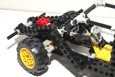
Motorized
Drive
The rear axle is driven by a 9V motor through a belt and
pulleys. Subsequent to the belt is a set of 8 and 24
tooth spur gears. Finally, a 14 tooth bevel mates with the 28
tooth ring gear of the differential. This results in a gear ratio
of roughly 18:1 between the motor and the wheels.
The rear axle uses a differential gear to allow smooth turns since the
wheels can turn at different rates. It
incorporates a built-in 28 tooth ring gear which can work either as a
bevel or a spur, similar to the 24 tooth crown gear. It is made
to house 3 of the 14 tooth bevel gears. One is on each axle,
and one planet gear in the middle allows the axles to turn at different
rates. |
|
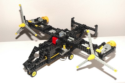
2nd
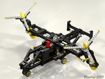
Model: Airplane
|
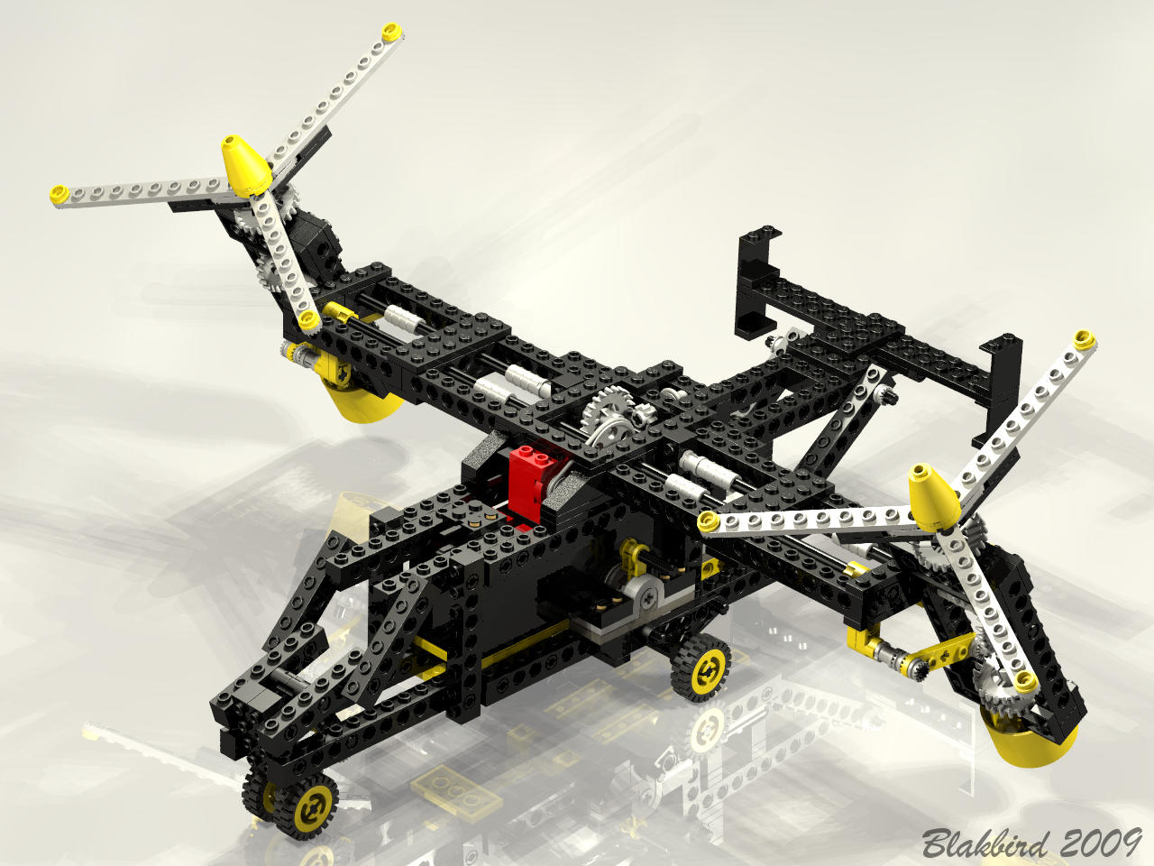
This
very
boxy
looking airplane seems to clearly represent a Bell/Boeing
V-22 Osprey. Considering that when this model was in development
the V-22 had only existed for a year or two, this model is pretty
topical and the details are even fairly scale. The V-22 can
sustain fixed wing forward flight like an airplane, but can also rotate
the huge 3-blade props vertical and hover like a helicopter.
The battery box is housed within the fuselage. There is a pole
reverser on either side of the landing gear fairing which controls the
motor functions.
|
Click
to download the LDraw
file of this model.
Model by Benjamin Wendl
|
|
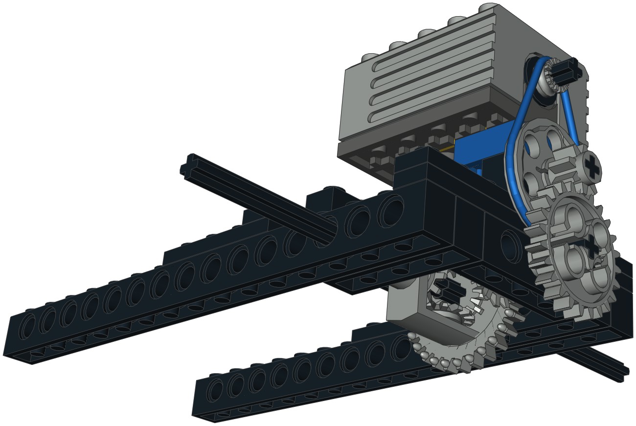
Rotating Props
The propellers are housed at the wingtips in huge nacelles. Each
engine has a faux turbine engine at the rear which does not actually
move.
A 9V motor in the fuselage drives a pair of pulleys through a belt,
reducing the speed 3:1. A second set of pulleys have equal size
so result in no further adjustment. An 8 tooth pinion next mates
with a perpendicular 24 tooth crown, further reducing the speed.
This crown drives an axle which runs the full span of the wing into a
crown gear at either end. Because the crown gears both face
inboard, the props rotate opposite directions. This is as it must
be on the real plane or the torque of the props would cause the entire
aircraft to yaw continuously. On the real plane directional
control at low speed can be controlled by adjusting the relative shaft
speeds of the two props. On the model the props are hard geared
together, so no relative motion is possible.
It may look like the animation is bouncing, but I'm sure that is a
result of the massive turbulence spawned by the props rather than due
to any incompetence on the part of the animator.
|
|
|
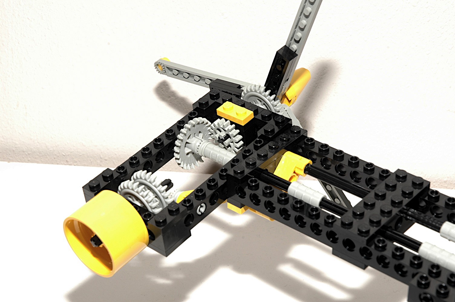
Pivoting
Nacelles
The engine nacelles can be rotated longitudinally through an angle of
about 90 degrees, from forward to up. This motion is powered by a
micro motor in the fuselage driving a pair of pulleys through a belt.
The linkage and axles are not very stiff which tends to result in a lot
of oscillation (bouncing) if the nacelles are rotated while the props
are turning.
Note that the rotation of the nacelles must necessarily be around the
axis of the propeller drive axle. This means that the pivot
mechanism was forced to be offset from this axis. As a secondary
effect, this means that the props turn slightly as the nacelles
pivot. You can see this in the animation.
|
|
3rd
Model: Rabbit
|
"That's
no
ordinary
rabbit!" When seeing this, expect that
perhaps Sirs Gallahad, Lancelot, and Bedevere may spring out of it at
any moment, taking the French completely by surprise.*
* I
apologize who anyone who is
not a fan of Monty Python, since you probably have no idea what I am
talking about. You don't know what you are missing.
|


Click
to download the LDraw
file of this model.
Model by Benjamin Wendl
|
|
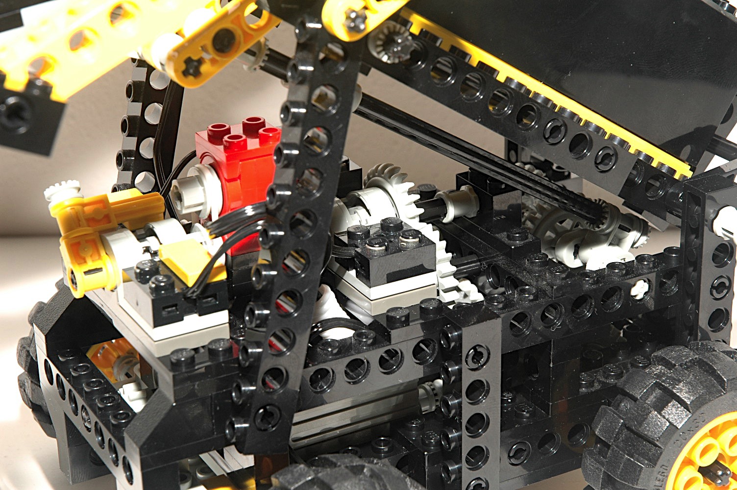
Feedback Loop
This robotic cat/rabbit thing is ugly which kept me
from building it for
many years. However, the internal mechanical workings are
fascinating. The primary motive power comes from the large 9V
motor. This motor is also coupled to a gear system which rotates
a pole reverser. This pole reverser controls the voltage polarity
to the micro motor. The micro motor is attached to another pole
reverser and serves only the reverse the main motor. This results
in a feedback loop which alternates the various functions which are
explained in detail below.
The animation really does not do this justice, but it gives you the
general idea. Also note that animation shows the model moving
significantly faster than it really does.
|
|
|
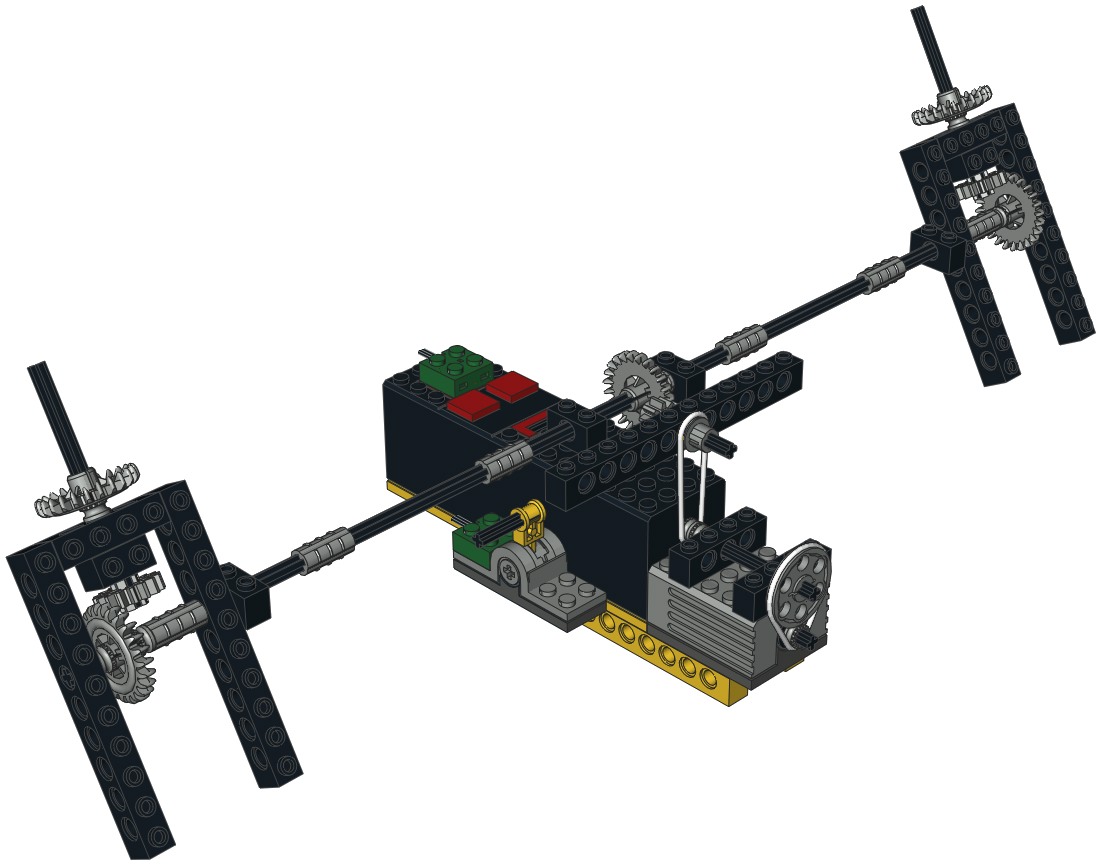
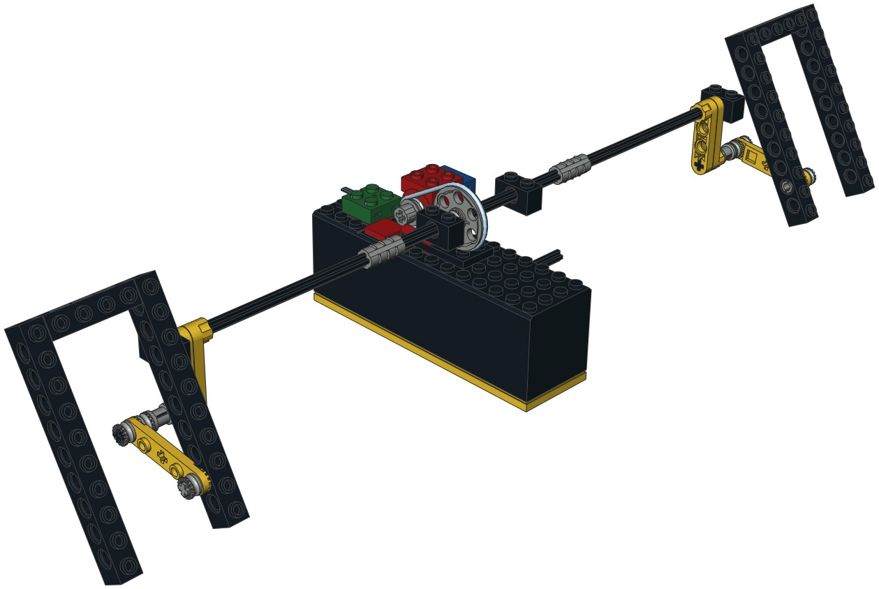
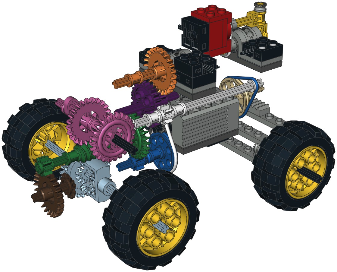
Flailing (and
other functions)
The main 9Vmotor drives a host of functions in parallel, so I had to
use lots of colors in the computer image to help make sense of it
all. There are 4 total parallel driven functions.
Let's start at the motor output shaft. This drives the blue
pulley through a belt which allows the motor to slip if the resistive
torque becomes too high. The blue pinion gear drives the green
crown. At this point the functions split in to parallel paths, so
I'll stick with the path to the drive wheels. The green pinion
gear mates with the brown crown. The brown bevel gear drives the
ring gear of the differential. The diff
incorporates a built-in 28 tooth ring gear which can work either as a
bevel or a spur, similar to the 24 tooth crown gear. It is made
to house 3 of the 14 tooth bevel gears. One is on each axle,
and one planet gear in the middle allows the axles to turn at different
rates. The final gear ratio between the motor and the rear wheels
is about 54:1.
The first parallel path splits off of the green axle at the worm gear
which drives the pink 24 tooth crown. At second pink crown mates
with a white 8 tooth pinion. The white pulley at the far end of
this axle drives the tan pulley through a belt. The tan pinion
drives the steering rack. The belt allows the axle to slip once
the steering is bottomed. The
steering mechanism itself uses
control arms and toothed links.
Moving back to the white axle we can see the next parallel path.
The white pinion drives the purple spur gear. A purple pinion
drives the orange crown. The orange axle then turns the center of
the first pole reverser. This pole reverser controls power to the
red micro motor. The orange axle rotates continuously
(+/-). The gear reduction at the pole reverser is extreme:
(3/1) * (24/8) * (24/1) * (8/24) * (24/8) * (24/8) = 648:1.
The final path is controlled by the end of the pink axle where you can
see a crankshaft element. The second computer image shows the
long black axle which connects to this crank, producing an oscillating
motion. The black axle drives the yellow crank. Rotation of
the crank axle waves the arms up and down through the yellow toothed
links. The yellow crank is also connected the lower jaw which
opens and closes at the rear pivot axle.
Eveery time the pole reverser rotates 90 degrees, the micro motor is
activated which then reverses the polarity of the main motor. The
result of this feedback is that the model first drives forward while
turning alternately left and right, all the while waving the arms and
opening the mouth. Then the main motor reverses and the model
drives backward. This continues until the batteries run out.
|
|
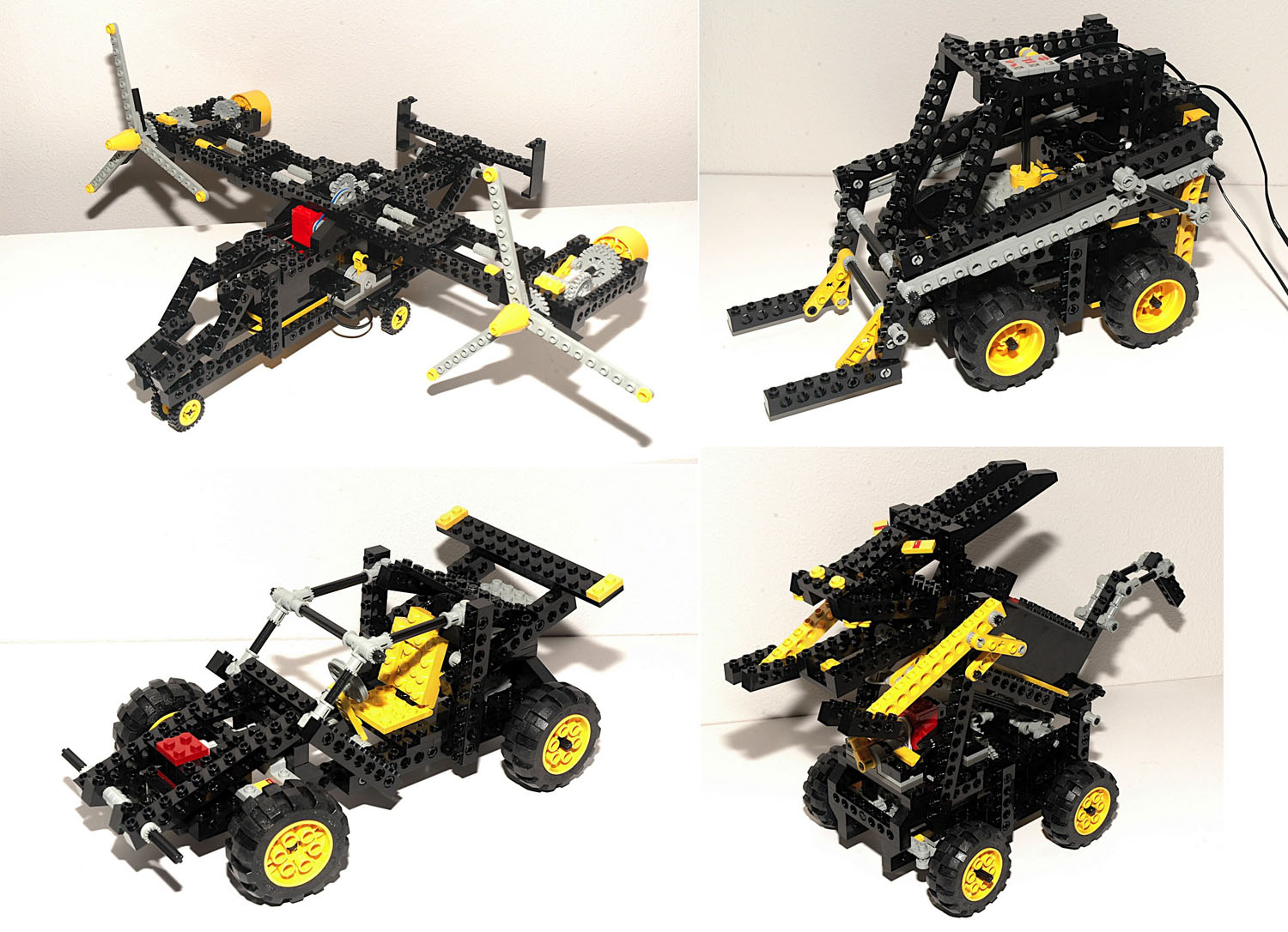
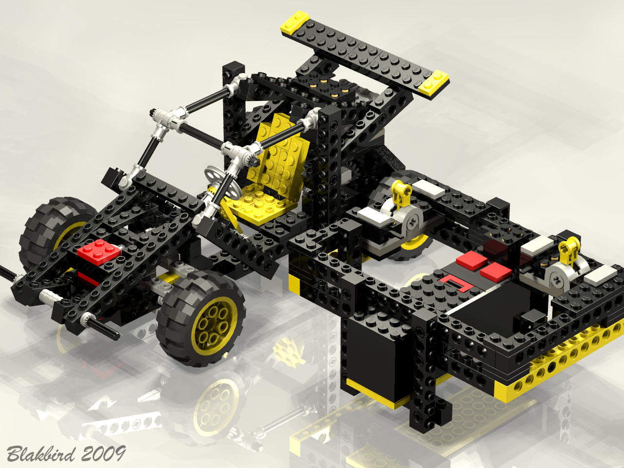
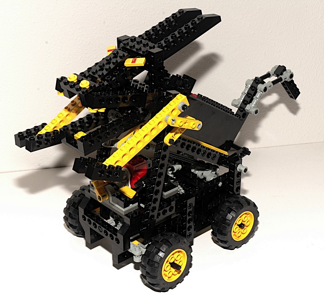
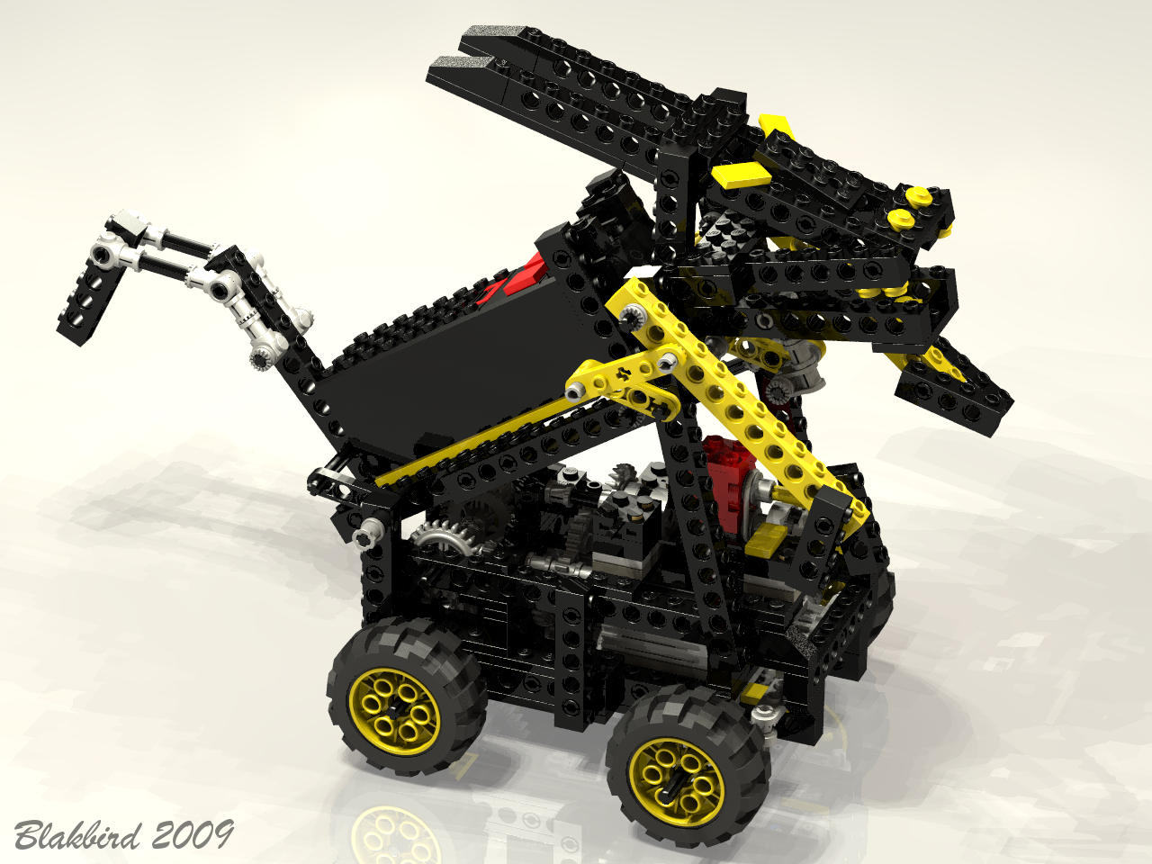
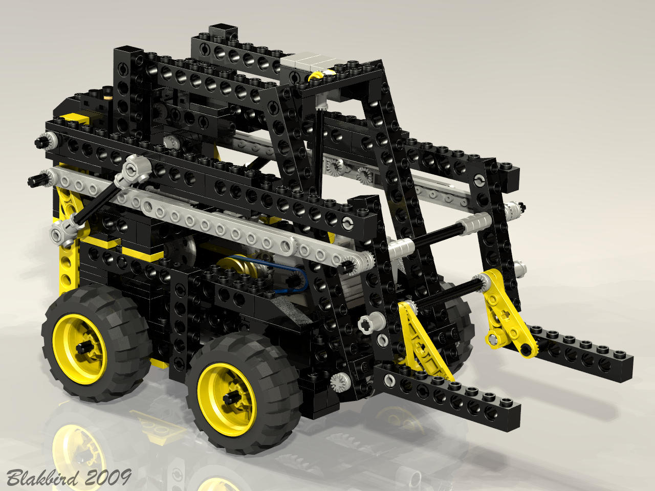
4th
Model: Forklift
|
This
skid
steer
forklift is a marvel of mechanical engineering. The
designer should be proud. The model drives forward and backward,
turns left and right, and raises and lowers the forks. All of
this is accomplished with one main drive motor. The micro motor
is used as a sort of mechanical transmission, shifting between the
primary functions.
|


Click
to download the LDraw
file of this model.
Model by Benjamin Wendl
|
|
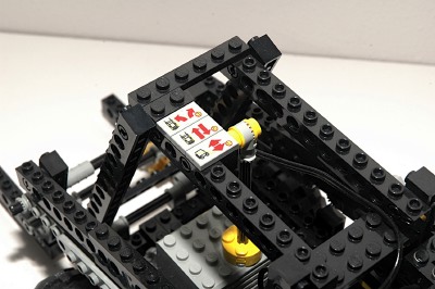
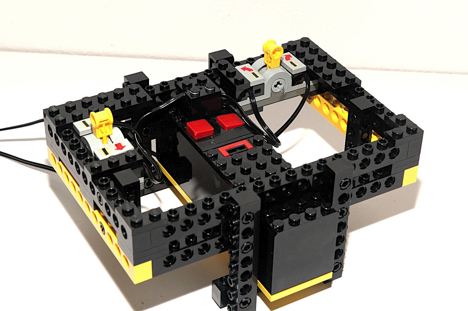
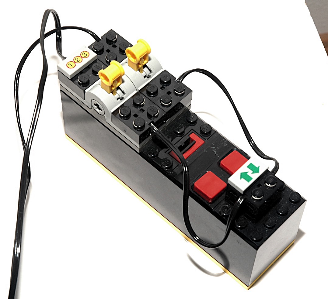
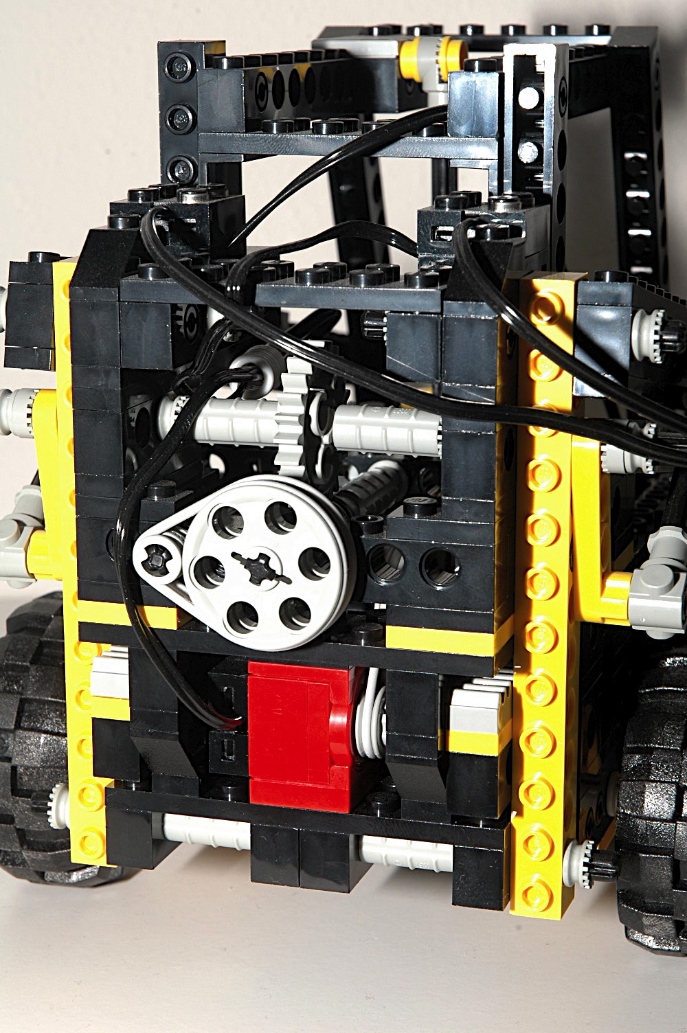
Controller
The model is controlled from a remote controller built around a 9V
battery box. There are 2 pole reversers housed on the front which
control the varoius functions of the model through a pair of wires
running into the top/rear of the forklift. Both motors can be
operated simultaneously.
|
 |
|
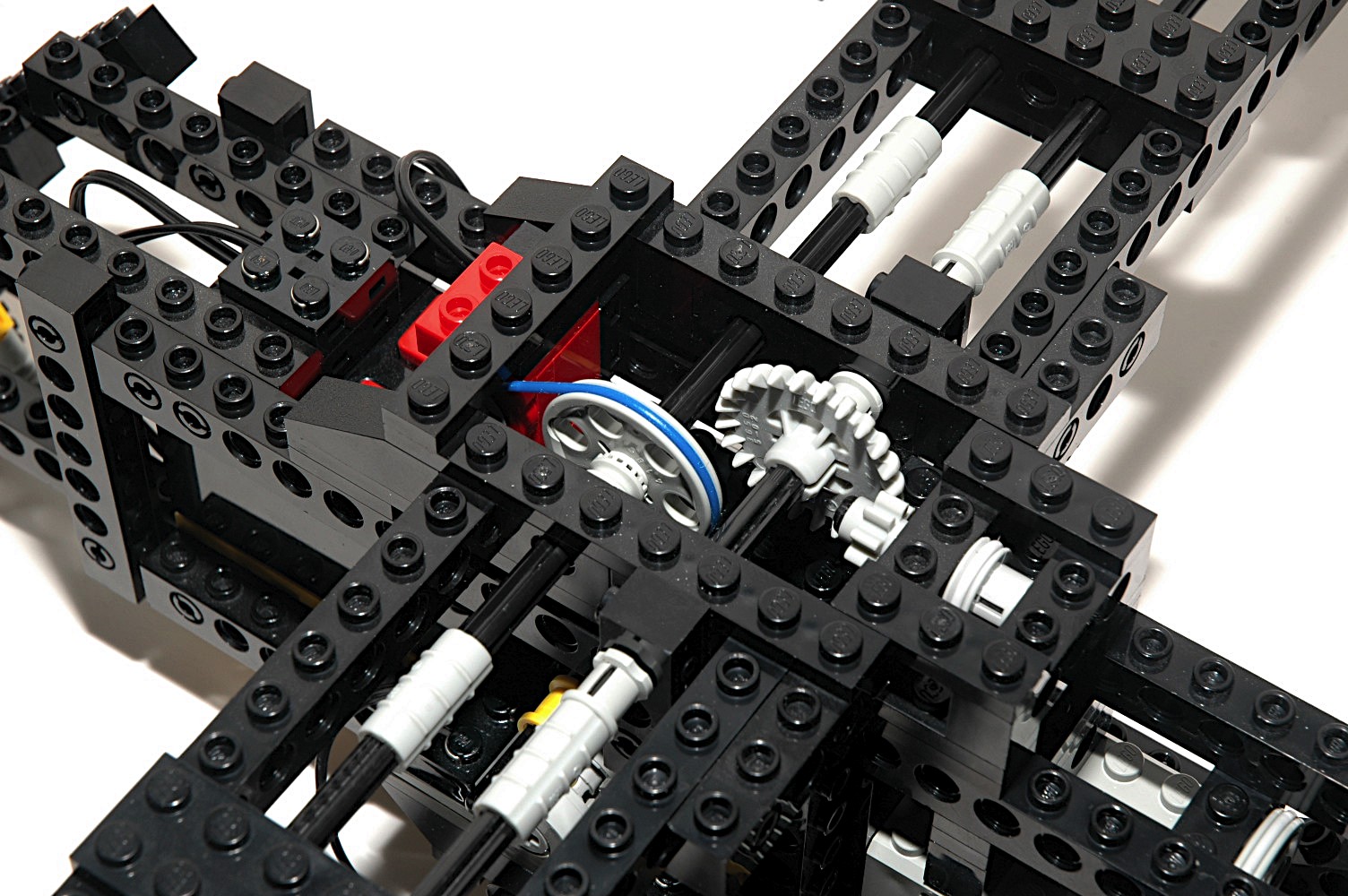
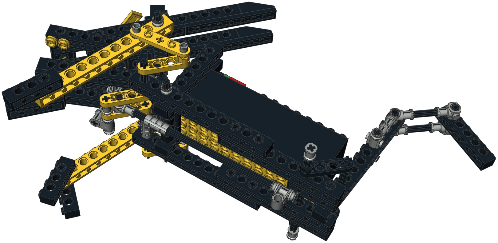
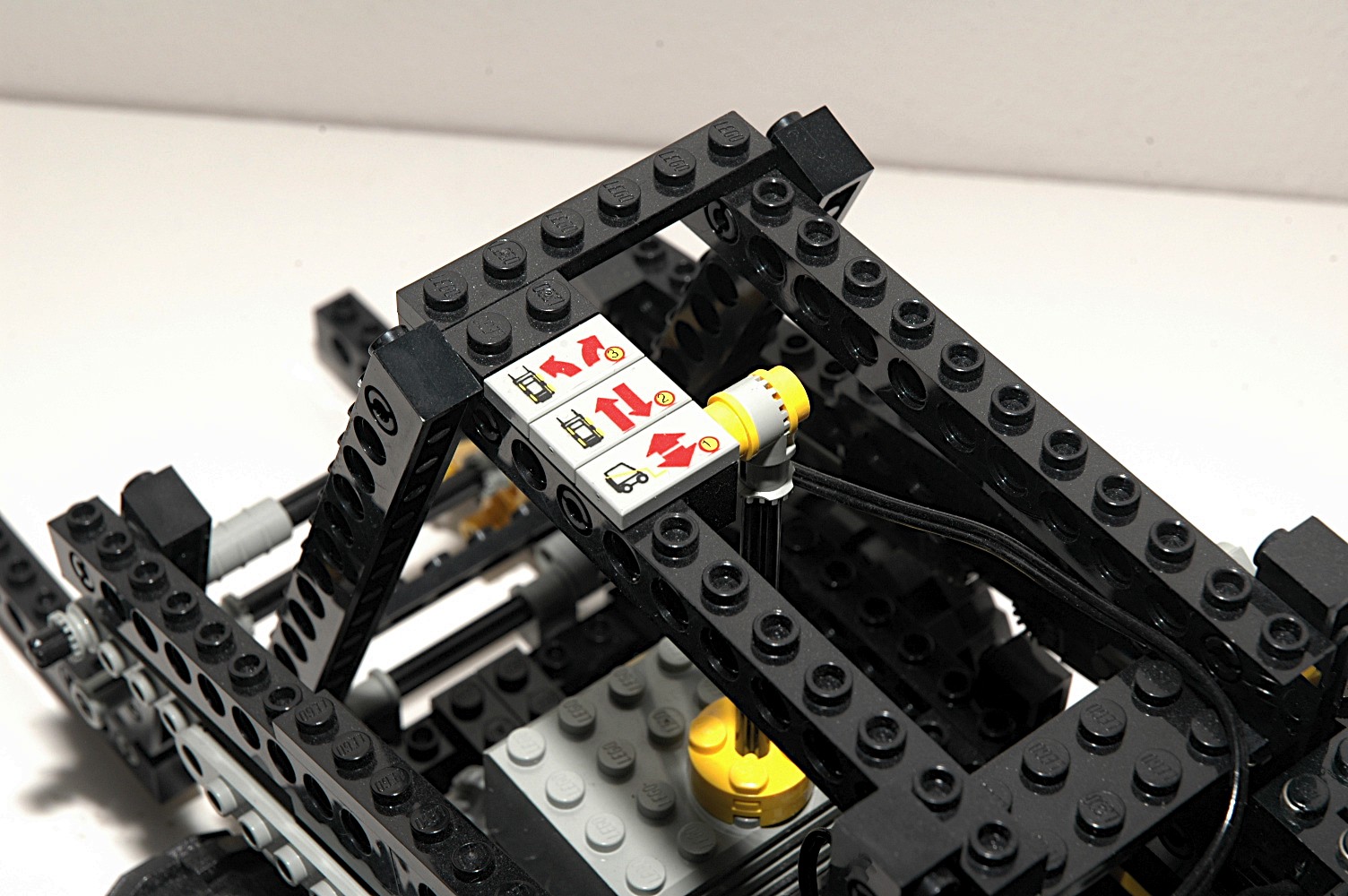
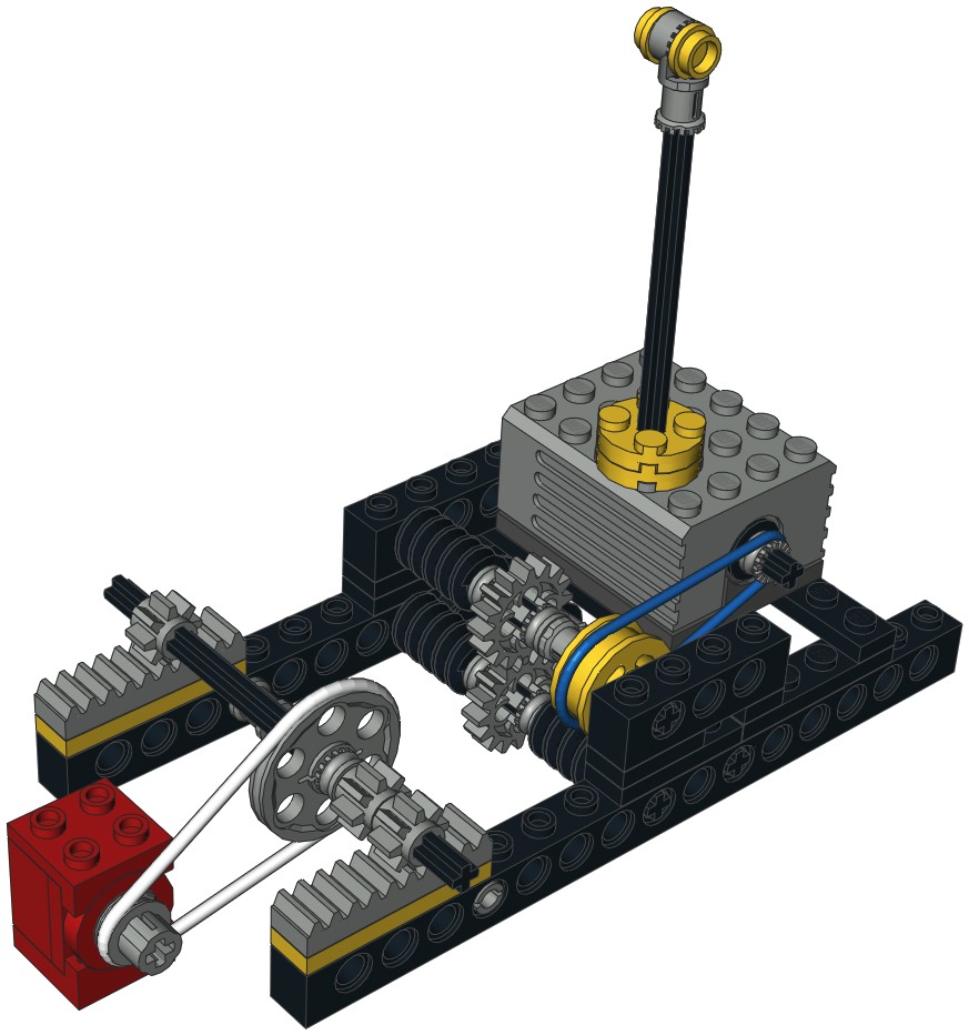
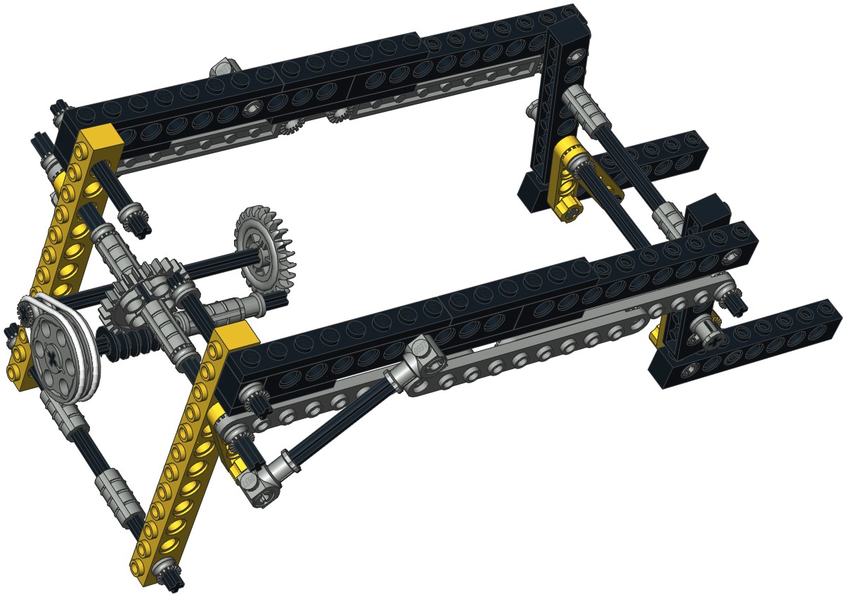
Function
Shifting
The multi-function use of this set comes from a translating rack
transmission. The red micro motor moves everything you see in the
computer image. A pulley drives an axle with a pair of pinion
gears at the ends. The pinions drive a pair of racks which
translate the whole primary motor assembly. In the other image
you can see the "indicator" which shows the operator which gear they
are in. The indicator aligns with one of the 3 different tiles at
each function.
The main motor drives a pulley wheel through a belt. The belt
axle drives a worm gear as well as a pair of 16 tooth spur gears.
The second spur axle drives another pair of worms. All 3 of these
worms are therefore rotating whenever the main motor is powered.
Translation of the rack system causes the worm gears to mesh with
various different other gear systems, thus controlling multiple
operating functions of the vehicle.
Although difficult to see in the image, there is another axle behind
the one with two worm gears. This has a worm gear on only one
side as is not connected to anything else. This may at first seem
useless, but the point is revealed further down.
|

Click for an animation of the
function shifter in motion. |
|
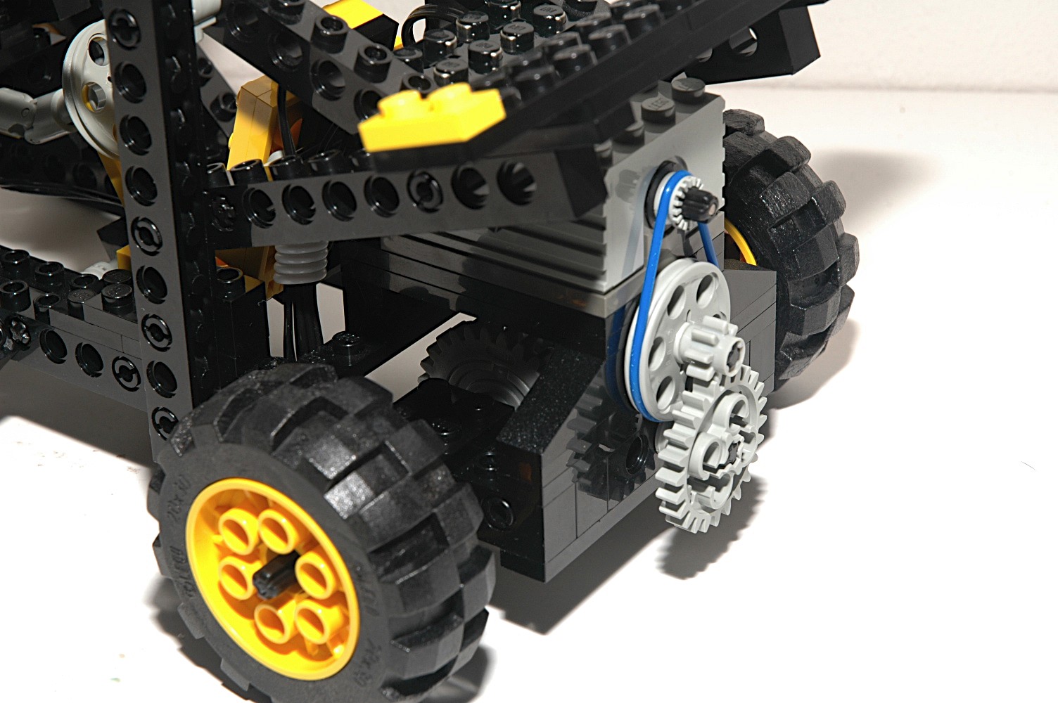
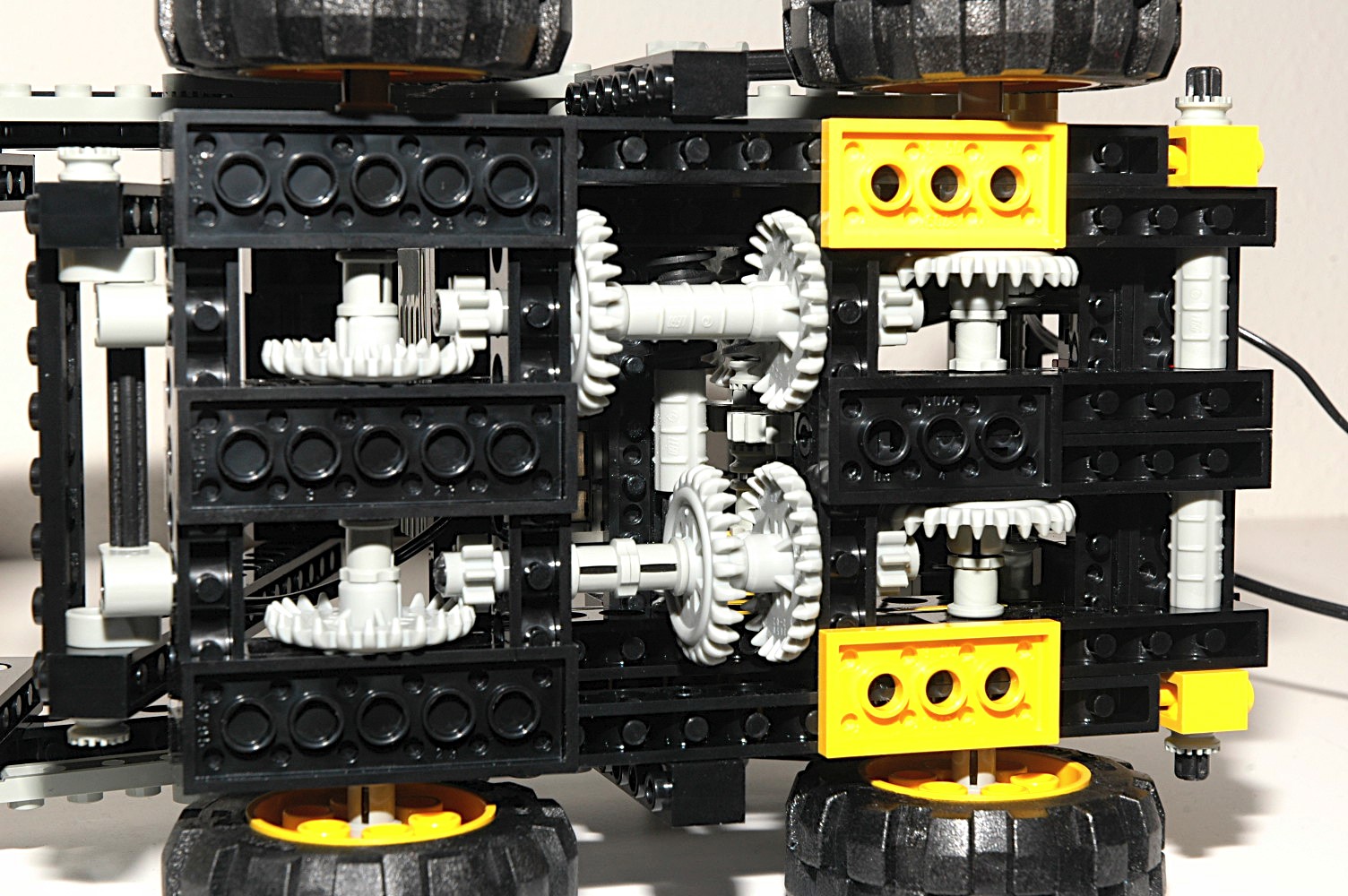
Driving and
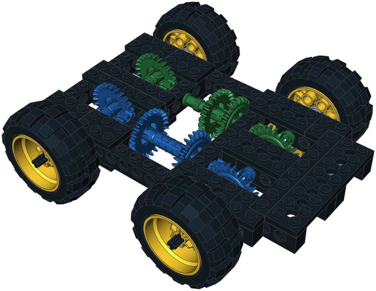
Steering
The skid steer locomotion system is 4 wheel drive. The blue gears
drive the left side and the green gears drive the right side. You
can see that one pair of blue and green crown gears are aligned along
the length of the vehicle. When both driven worm gears mate with
these, the entire vehicle moves forward or backward.
The second pair of blue and green crown gears are not
aligned. The green gear halfway along the length of
the vehicle ends up mating with one of the driven worm gears, so the
right wheels still turn. The second blue gear mates with the
mystery worm gear we heard about earlier. Since worm gears cannot
be backdriven, this idler axle effectively locks the wheels on the left
side. This allows skid steering of the vehicle.
|
|
|
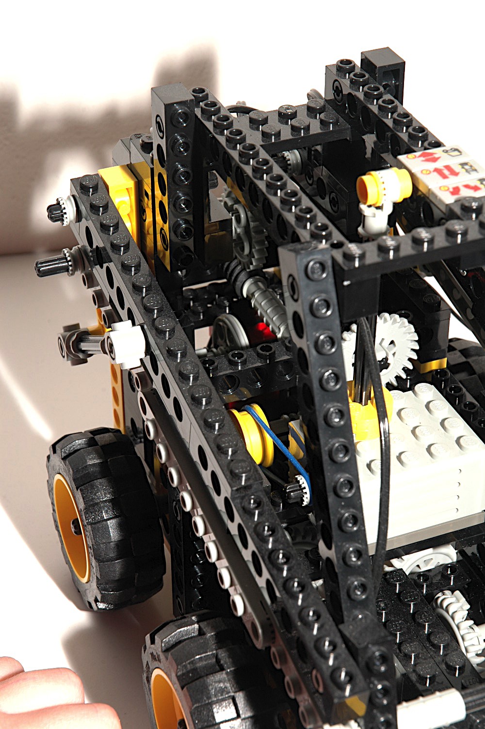
Lifting
The third function is lifting of the forks. When the drive system
is translated all the way into the aft position, the upper driven worm
gear drives the 24 tooth crown in the computer image. The next
axle uses a pair of belts and pulleys to transmit torque. The
axle driven the large pulleys turns another worm gear which drives a 24
tooth spur gear. This final gear turns an axle which pivots a
crank arm of the main fork arms. The fork mechanism is a 4-bar
linkage which remains parallel to the ground.
Because there are two stages of worm gearing in series, this lift has a
massive gear reduction of about 3500:1! This, along with the rear
pivot point, gives the forks a lot of lifting power and no chance
whatever of backdriving the motor.
The forks do not tilt.
|
|


