Code Pilot
|
|
Code Pilot
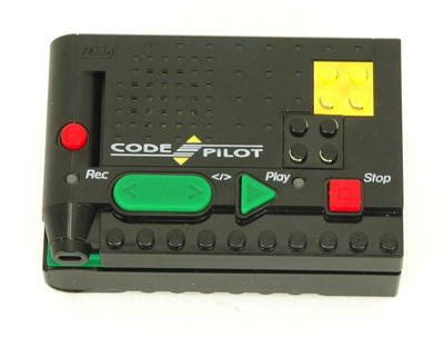
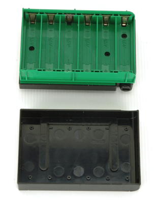
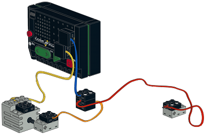
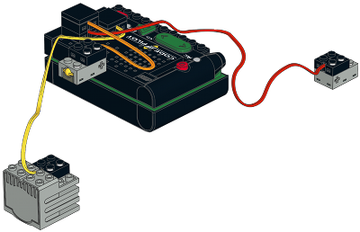
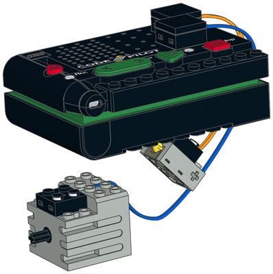
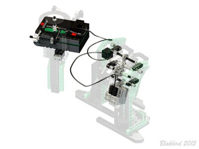
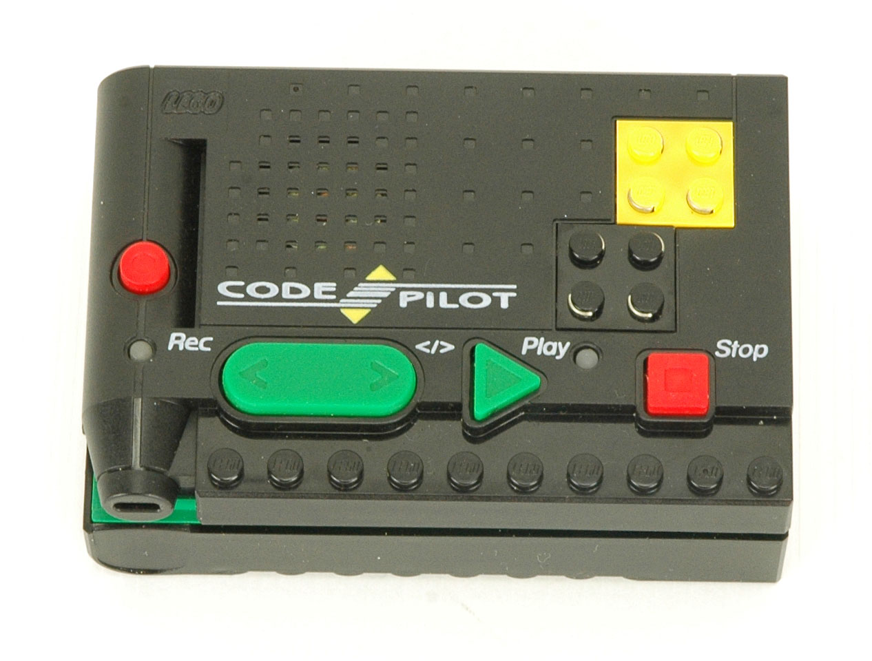
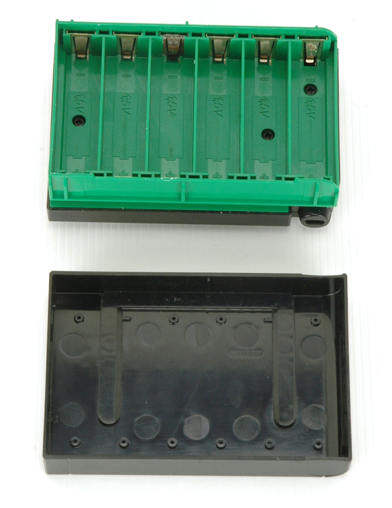
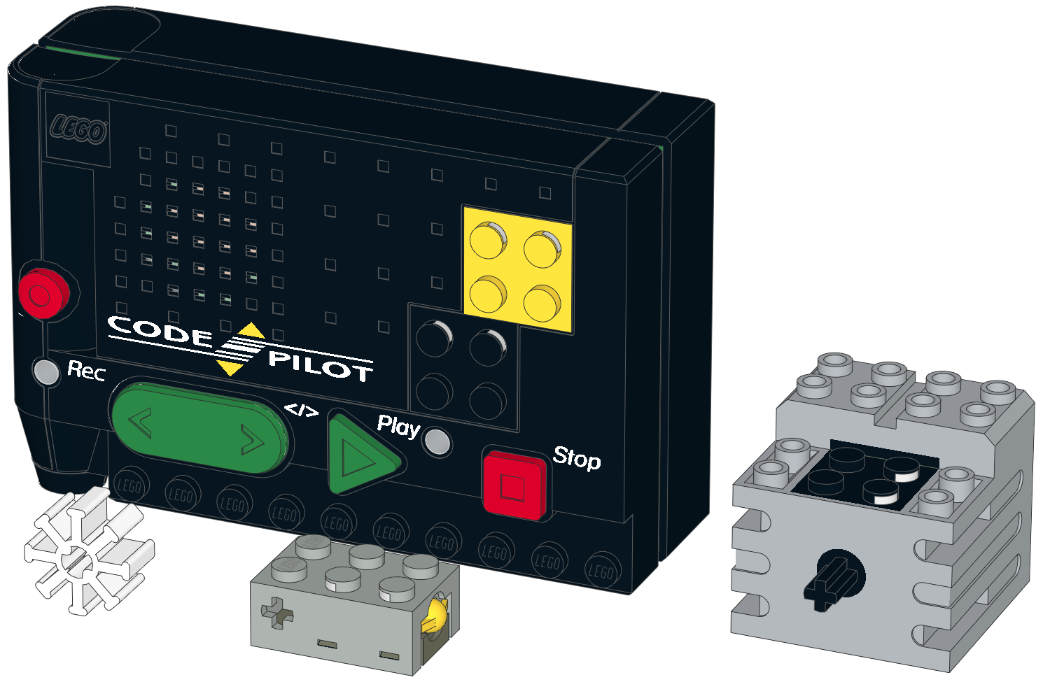
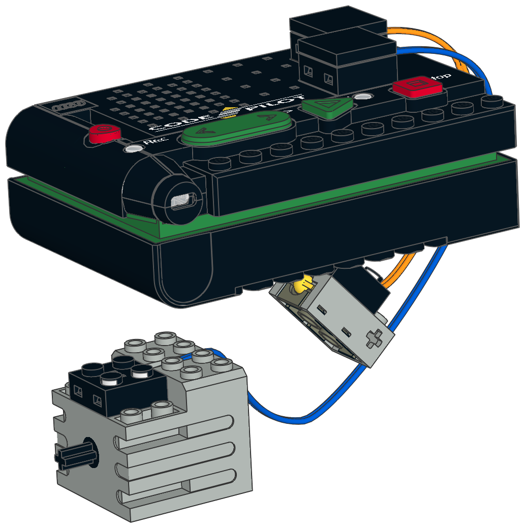
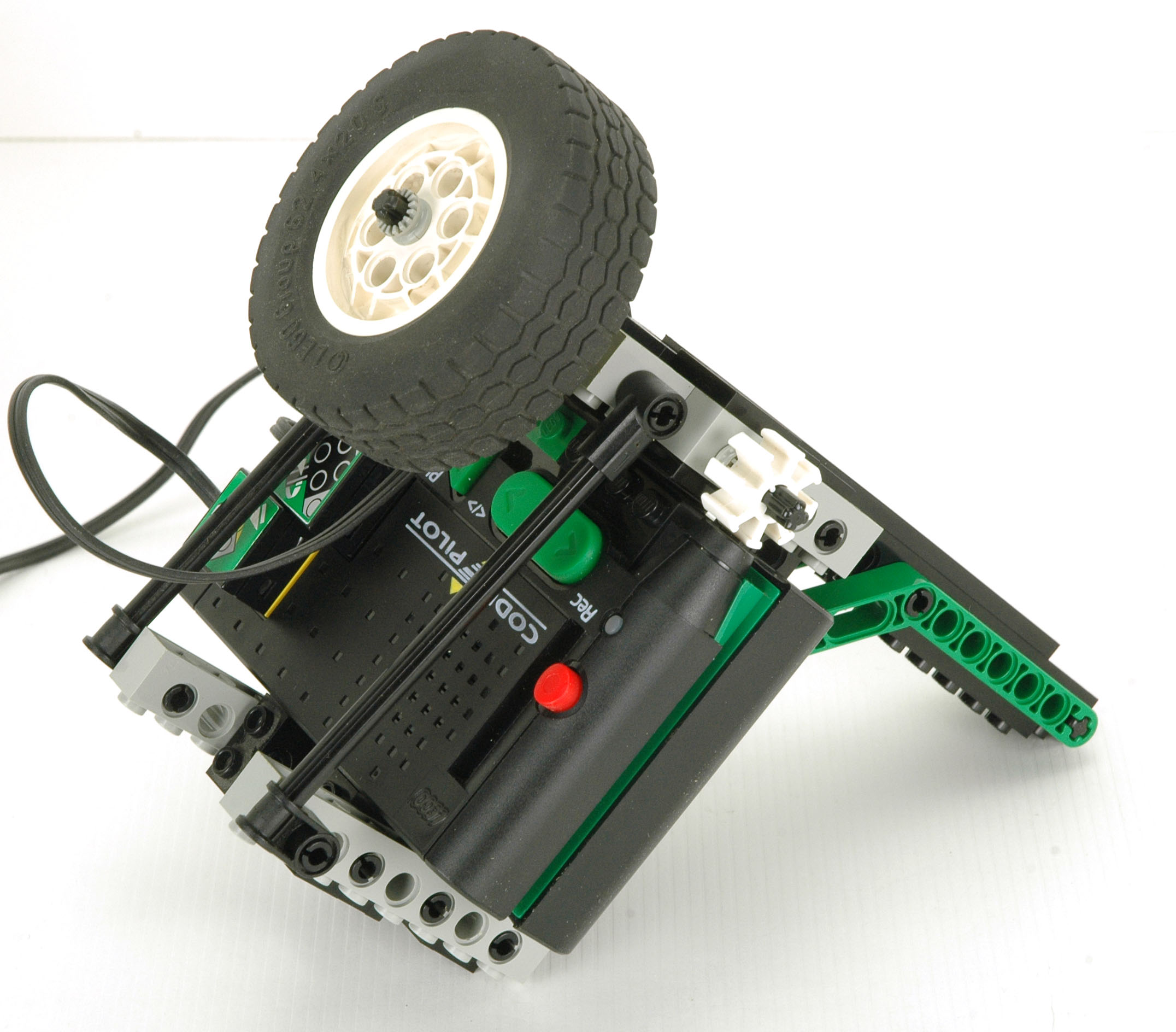
The Code Pilot is a 12x8x4 stud programmable electric brick that houses 6
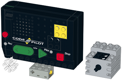
AA batteries. It has a single 9V output port for a motor (colored black) and a single input port for a switch (colored yellow). It is intended to work with the new 9V motor and the new touch sensor (both shown in the computer image).
The motor has internal gearing and turns at a much lower rate with
higher torque than the previous motor. The touch sensor is nothing
more than a momentary contact switch that, when depressed, creates
continuity between its two contacts.
The key to programming the Code Pilot is the barcode reader at lower
left. When the "record" button is pushed, the sensor can accept
barcodes from the included code card. Each code is nothing more
than a 3 digit number. There are a total of 44 different codes:
- 2 - sensor depressed or not
- 3 - motor clockwise, counterclockwise, or off
- 6 - sound waveforms: truck, helicopter, robot, gears, air, or off
- 1 - ampersand to combine sound with motor movement
- 12 - timer: numbers 0-9 in seconds, random, and decimal point
- 4 - sound waveform pitch variations for use with the timing wheel
- 12 - sounds representing the 12 notes of an octave of the chromatic scale
- 4 - preset programs for each of the 4 main models
Using these codes, a wide variety of programs can be written. 4
preexisting programs are available, one for each model. These
showcase only a small portion of the capability of the Code Pilot.
Besides controlling the motor, the system can also be programmed to
play music.
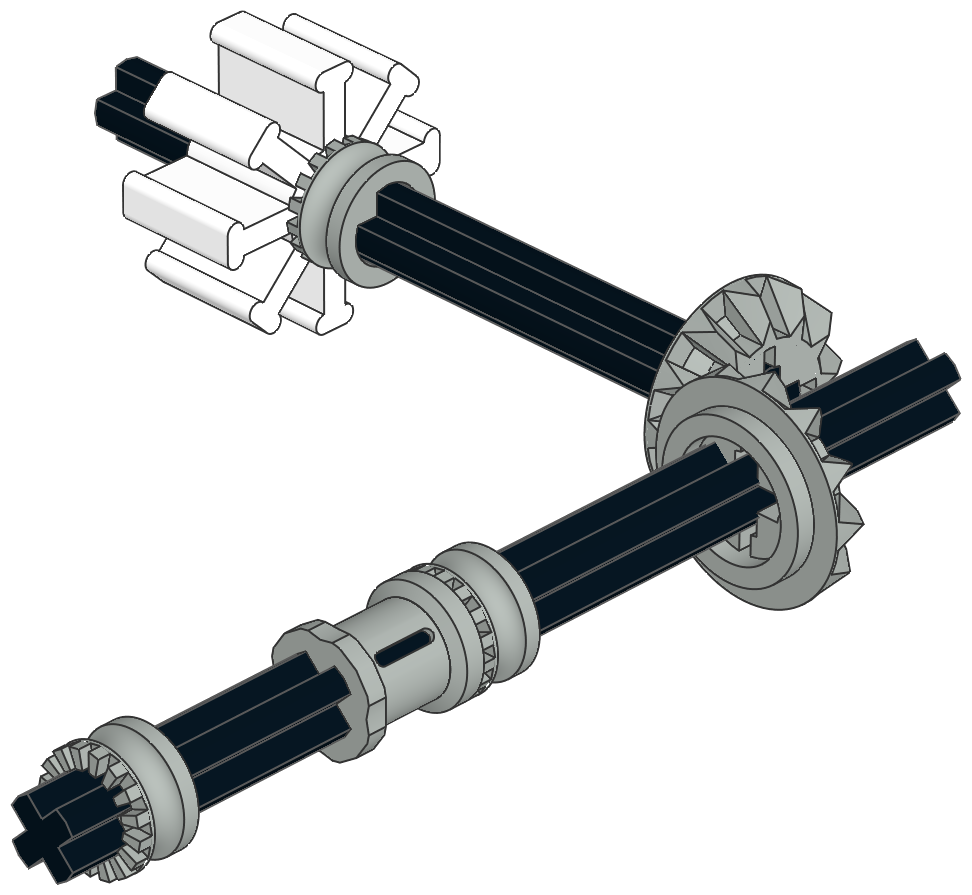
The barcode reader is not only used for programming. A special
timing wheel (shown in white) can be placed in front of the reader
within the model. When the wheel rotates, the reader senses the
motion and can vary the pitch of any of the sound waveforms or the speed
of the motor.
The programming language is never explained in detail. The
syntax is mostly inferred by observing the effect of the preexisting
programs on the models and comparing that to the example list of
barcodes used to achieve those programs.
|
|
1st
Model: Dump Truck
|
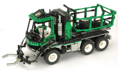
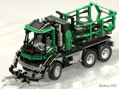
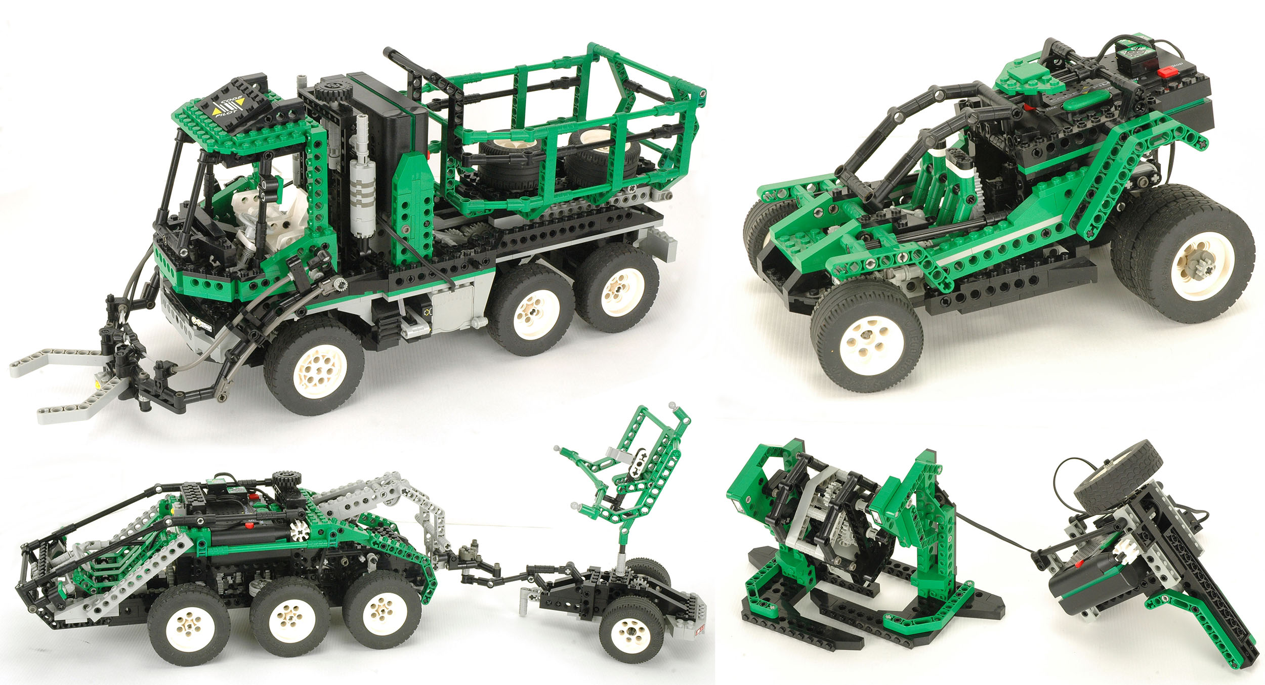
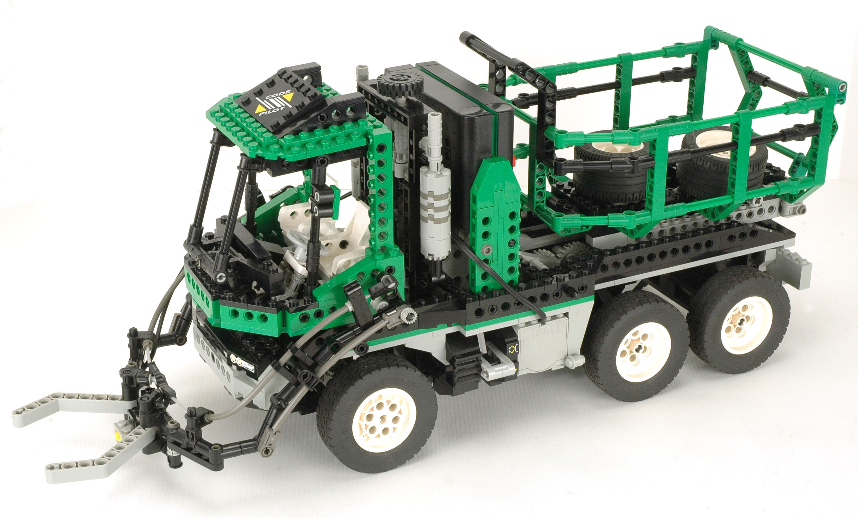
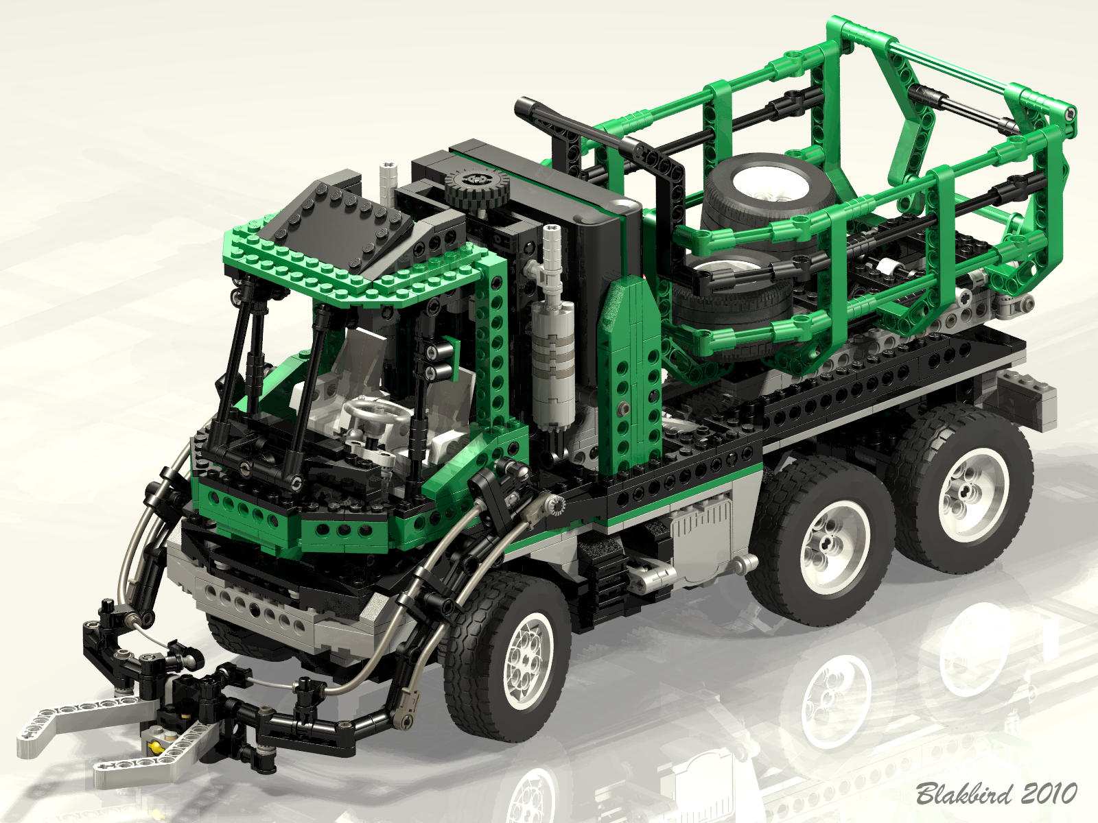
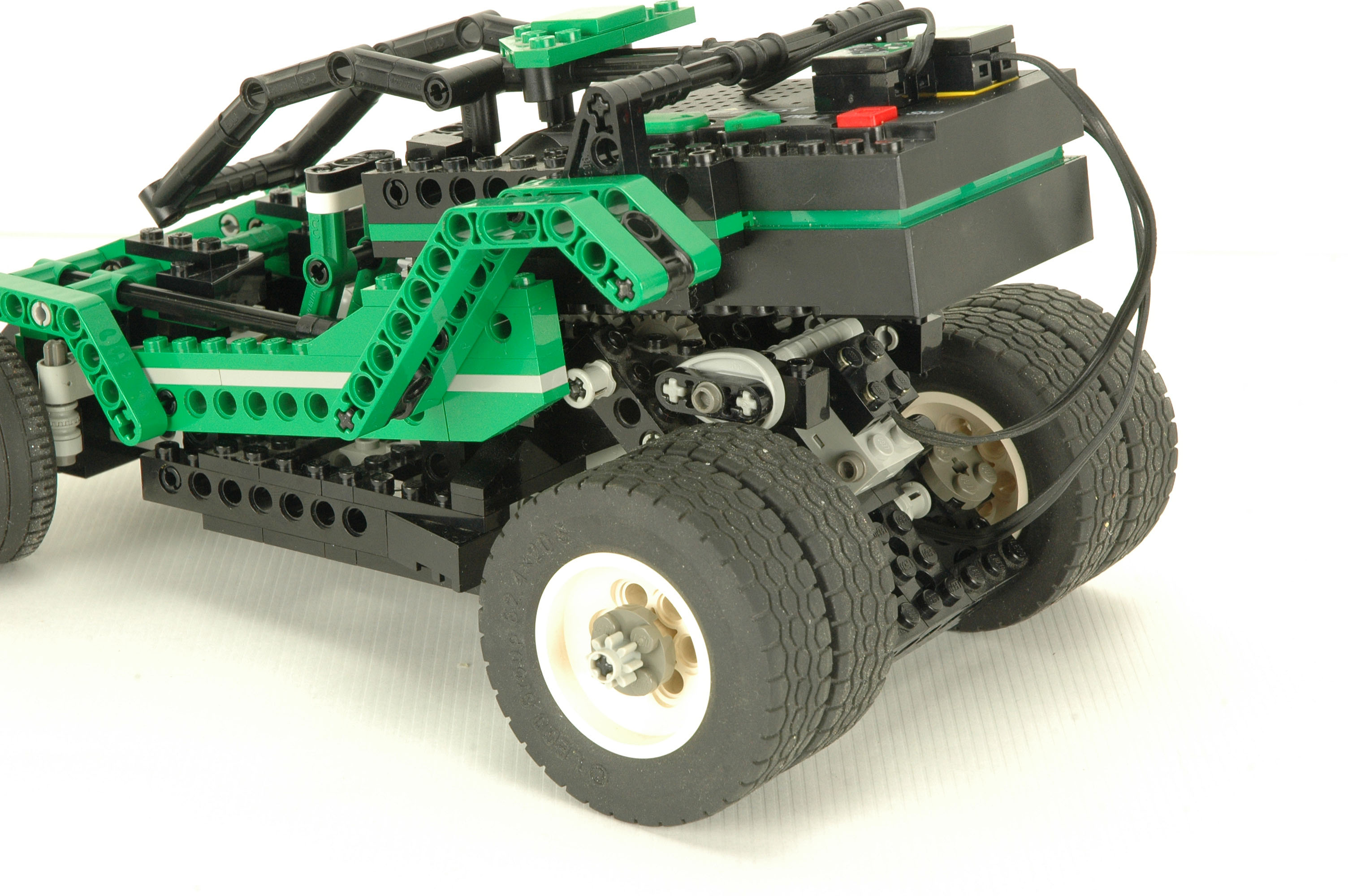
The garbage or refuse truck is clearly the flagship model of the set,
and exceeds the complexity of the others by a large margin. The
enormous model includes only a single motor, yet manages a plethora of
interesting features. The 6 wheeled vehicle uses the additional
two tires of the set as cargo.
When the program is run, an idling diesel sound is heard. The
vehicle can be pushed and steered manually. While the vehicle is
rolling, the timing wheel turns and is seen by the Code Pilot resulting
in engine sounds which increase in pitch with speed. When the
sensor at the front of the arm hits a tire, a blast of air is heard and
the engine idles up simulating powering the hydraulic system. The
arm then lifts the tire over the cab and drops it in the bed. With
a flip of the switch on the transmission, the single motor instead
powers the bed and raises it to dump the tires.
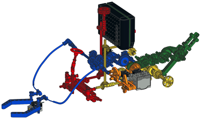
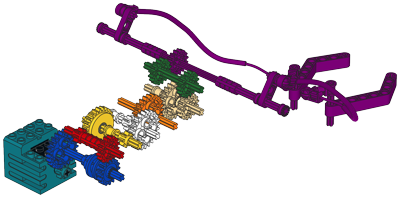
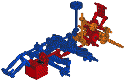
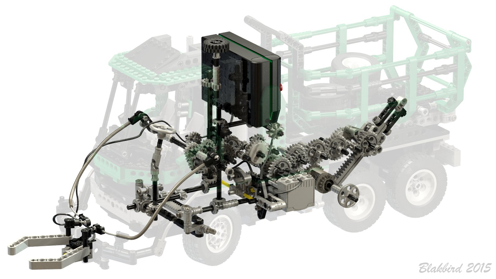
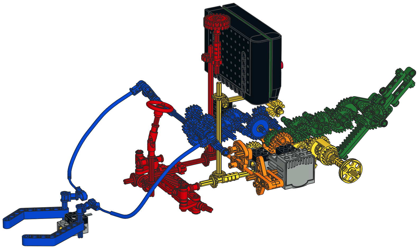
The computer image shows the tremendous number of gears and the way in
which the mechanisms are routed together. Blue is the arm
mechanism, red the steering, yellow the drive train, orange the
transmission, and green the dumping bed. Click the image for a
larger version to study the detail.
The model is capable of using a second motor on the other side to power
the wheels. This motor was available separately as a Supplemental Set.
The model is roughly to scale with Technic figures and has the right size seats, but no room for their legs.
|
Click
to download the LDraw
file of this model.
Model by Eric Albrecht
|
|
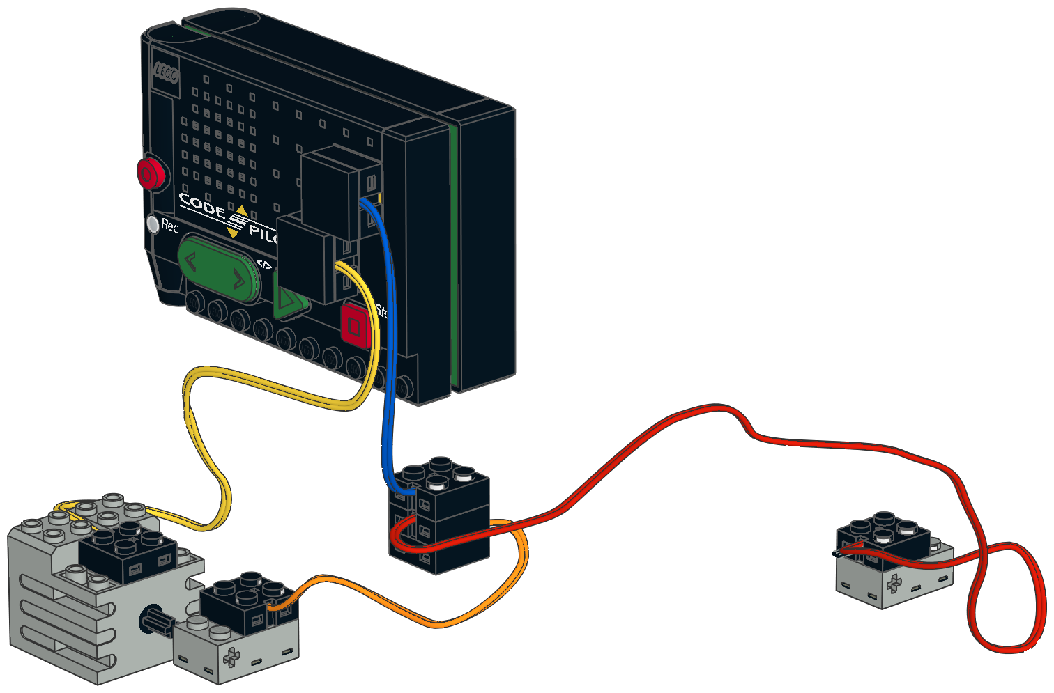
Electrical
The electrical system of the garbage truck uses everything the set has to offer: the Code Pilot, a motor, and two touch sensors.
Since the Code Pilot has only a single sensor port, both switches trigger
the same action. That action is running the motor for 11 seconds, then
reversing for 11 seconds. The position of the transmission controls
whether the arm or the bed moves. The mechanisms had to be geared in
such a way that both take about the same amount of time to reach their
full travel. That helps explain the huge gear train in the bed system.
|
 |
|
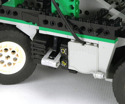
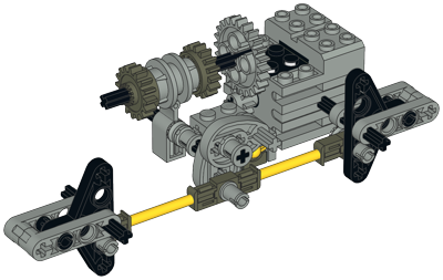
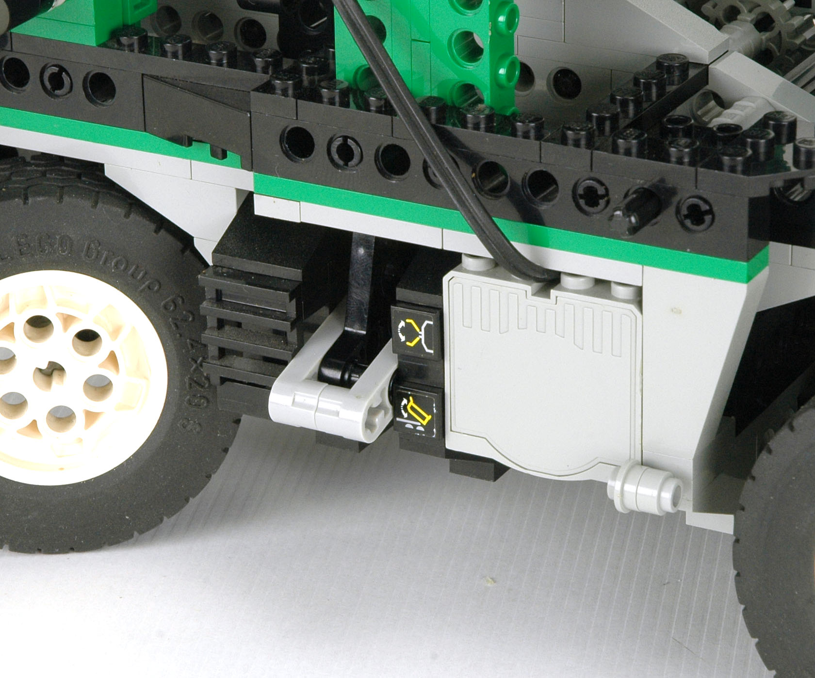
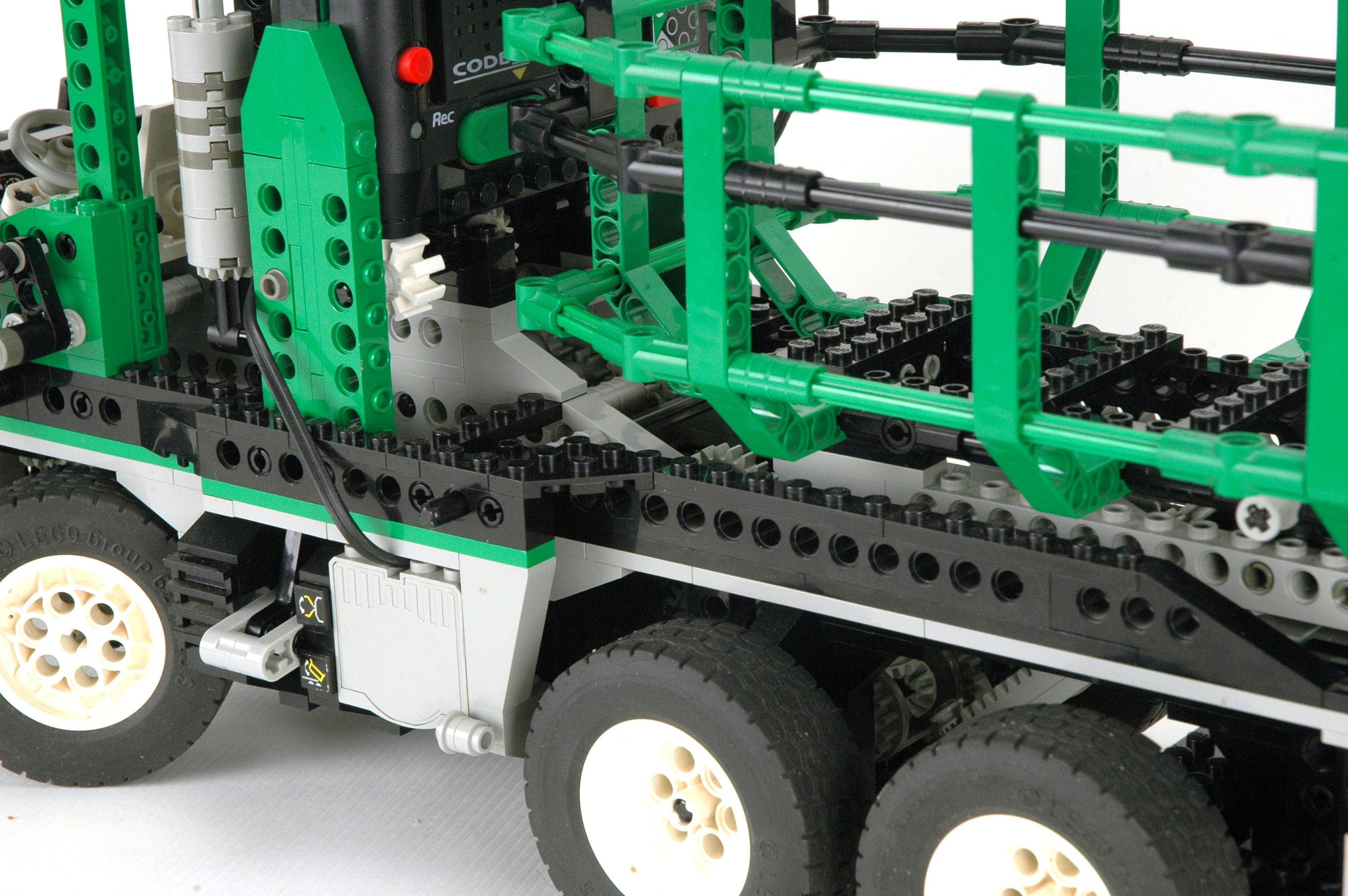
Transmission
The single motor is capable of driving either the arm or the bed
depending on the position of the transmission. The transmission
selection levers on the sides of the vehicle serve a dual purpose.
Not only do they mechanically slide the drive ring, they also rotate a
cam which pushes a touch sensor buried deep inside the vehicle.
Activating this touch sensor is the trigger which tells the Code Pilot
to dump the bed. When in arm mode, nothing touches the sensor and
the sensor on the arm is used instead. A short Flex System cable
connects the two levers to the central switching mechanism.
The animation shows how the driving rings work to engage and
disengage the clutch/idler gears. The driving ring is shown in
red. The
lower axles are joined with the gray axle joiner. The driving
ring rotates with the axles. At first, the driving ring is
disengaged so both the dark gray and green gears are not driven and
slip on the axle. The driving ring then engages the green gear
and
thus drives the blue gear. Because the driving ring does not use
gear teeth but
rather uses four tapered driving dogs, there is considerable backlash
between the driving ring and the gear. The allows the driving
ring to be engaged even while it and the mating idler gear are turning
at different speeds.
|

Click for an animation of
the transmission in motion.
|
|
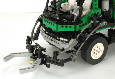
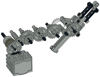
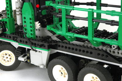
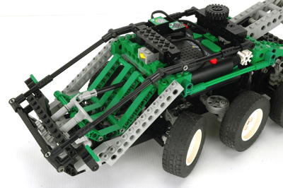
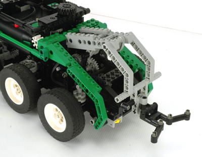
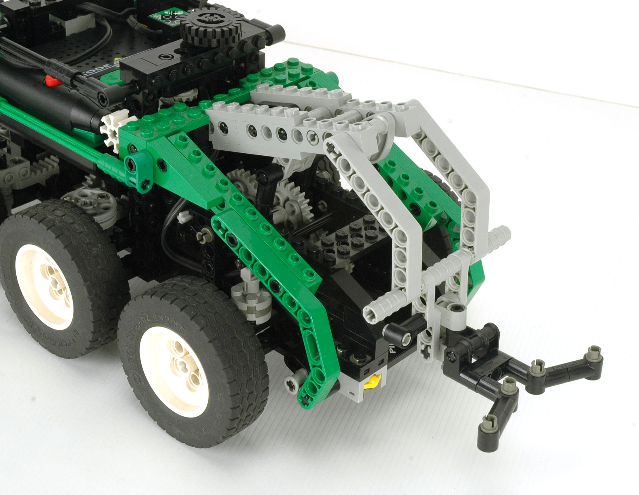
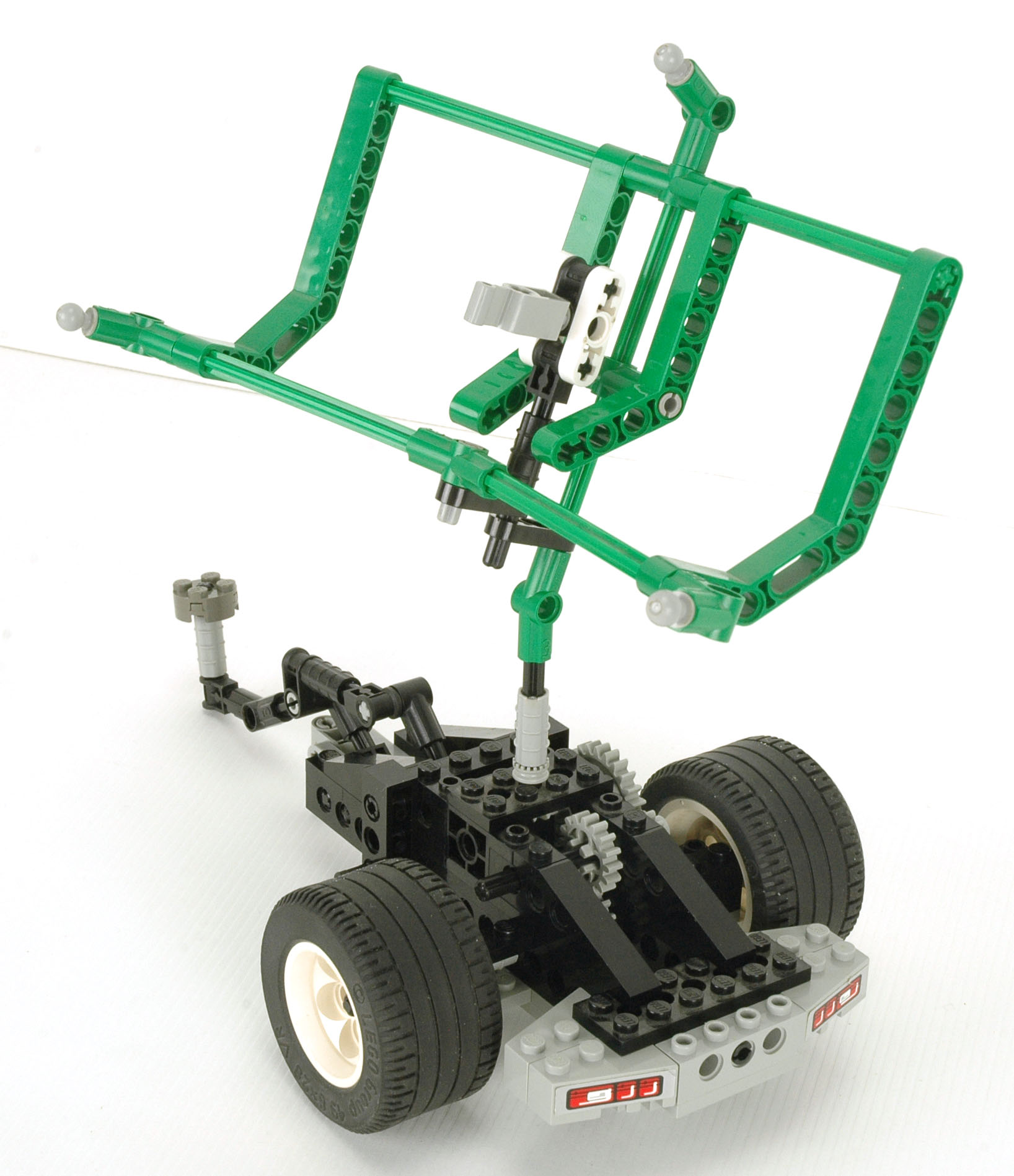
Loading Arm
The loading arm is the best and most clever part of the model.
First of all, it looks completely convincing made from the new angle
connectors and loaded with Flex System tubes that look like hydraulic
lines and wiring as well. The touch sensor at the mouth of the jaw triggers the system when it hits a tire.
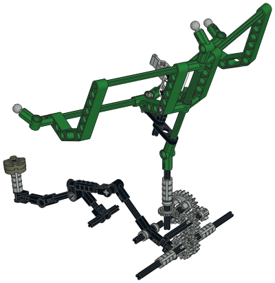
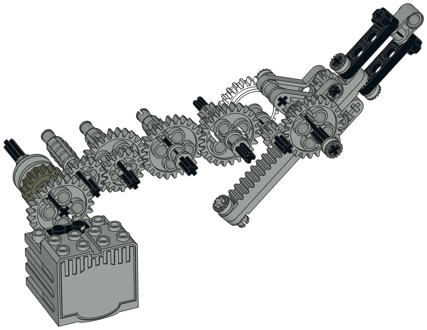
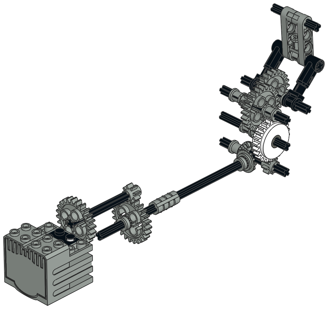
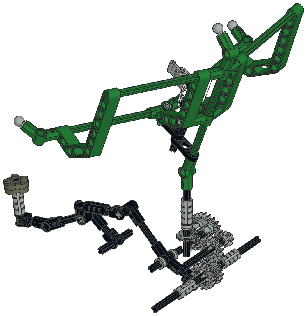
The gear system driving the arm powers only a single rotating axle, yet
the motion occurs in two stages. Study the computer image to see
why. Rotation of the input axle drives a pair of 3L liftarms used
as cranks with ball joints at the end. Pulling on the ball joints
retracts the Flex Cables which are connected to the jaws at the end of
the arm. When the jaws close on something and cannot move any
farther, the torque instead serves to lift the entire arm. After
the arm passes the balance point straight above the cab, it drops its
load into the bed. Reversal of the motor returns the arm to the
beginning of the cycle, ready to accept another tire. Watch the
animation to see the sequence.
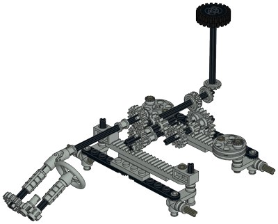
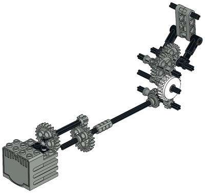
The color coded computer image should the multi stage gear reduction
from the motor to the arm. There are 3 sets of 3:1 reduction
resulting in a total of 27:1. This provides just enough torque to
lift the heavy arm. Note the clutch gear shown in yellow.
This part is needed to prevent the motor from stalling in case 11
seconds is enough to load the system into the stops. With 27:1
reduction, there is enough torque to destroy the Flex Cables. By
putting the clutch at the right stage in the gear system, there is still
enough torque to lift the arm but not enough to damage anything.
This mechanism was only possible with the Flex System and remains the best use of the System with the possible exception of the 8485 Dinosaur.
|

Click for an animation of
the loading arm in motion. |
|
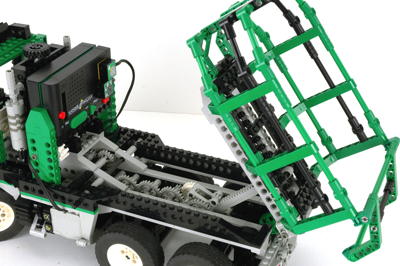
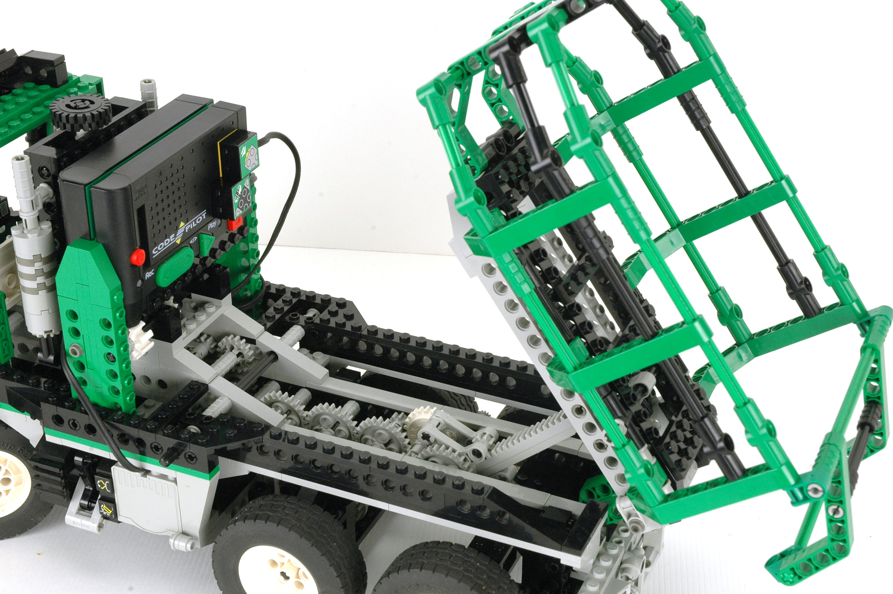
Dumping Bed
The motorized dumping bed uses a custom made mechanical linear actuation
system. 3 stages of 3:1 reduction result in a total reduction of
27:1, the same as the arm. The output is a gear rack used as a
linear actuator inside a housing made from Technic triangles. Like
the arm, this mechanism takes about 11 seconds to reach its full
travel. Also like the arm, it requires a clutch gear to keep the
motor from stalling. The bed raises to just over 45 degrees,
enough to usually dump the tires although they sometimes become trapped
by the lumpy base of the bed.
|
Click for an animation of
the bed dumping. |
|
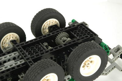
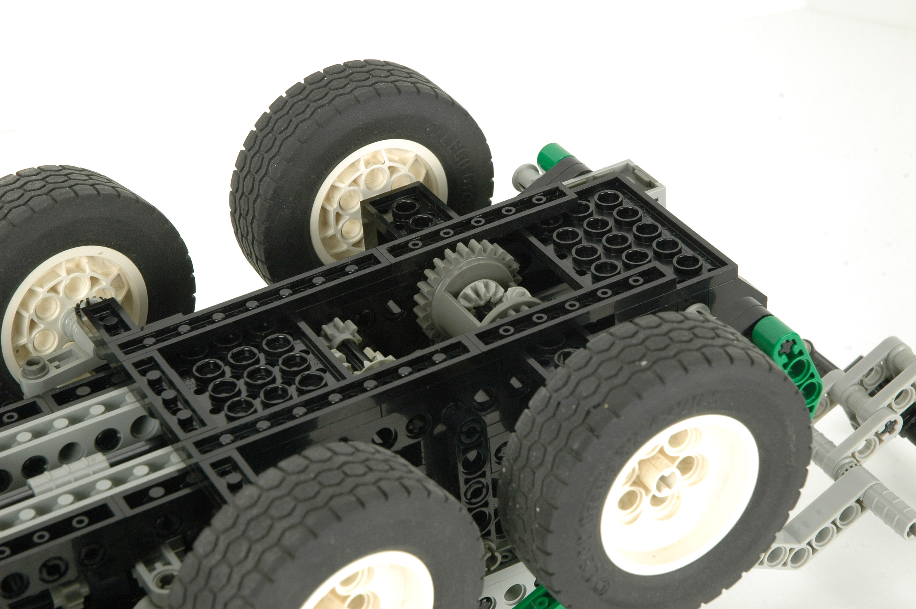
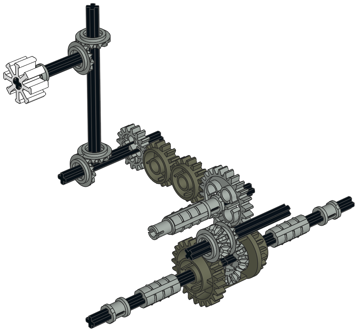
Drive Train
The middle of 3 axles is the only drive axle. This axle includes
simulated disc brakes, although a real heavy truck is likely to have
drums. A differential sits between the half shafts to allow
rotation of the tires at different speeds. A series of gears
transmit the rotation to the white timing wheel which is seen by the
barcode reader of the Code Pilot. Movement of the timing wheel
causes the pitch of the engine to change in 4 stages. The gear
ratio is important to allow the engine to respond to reasonable vehicle speeds.
A second motor (or the same motor) can be placed on the right side of
the vehicle to power the wheels with a 9:1 ratio. The motor
struggles with this load.
The problem with a 3 axle vehicle which powers only the middle axle is
that the middle wheels can easily come off the ground when going over a
dip in the road. The model solves that problem by having the rear
axle on a swing arm. The rear axle can therefore not support and weight so the middle axle is always on the ground.
|
Click for an animation of
the drive train in motion. |
|
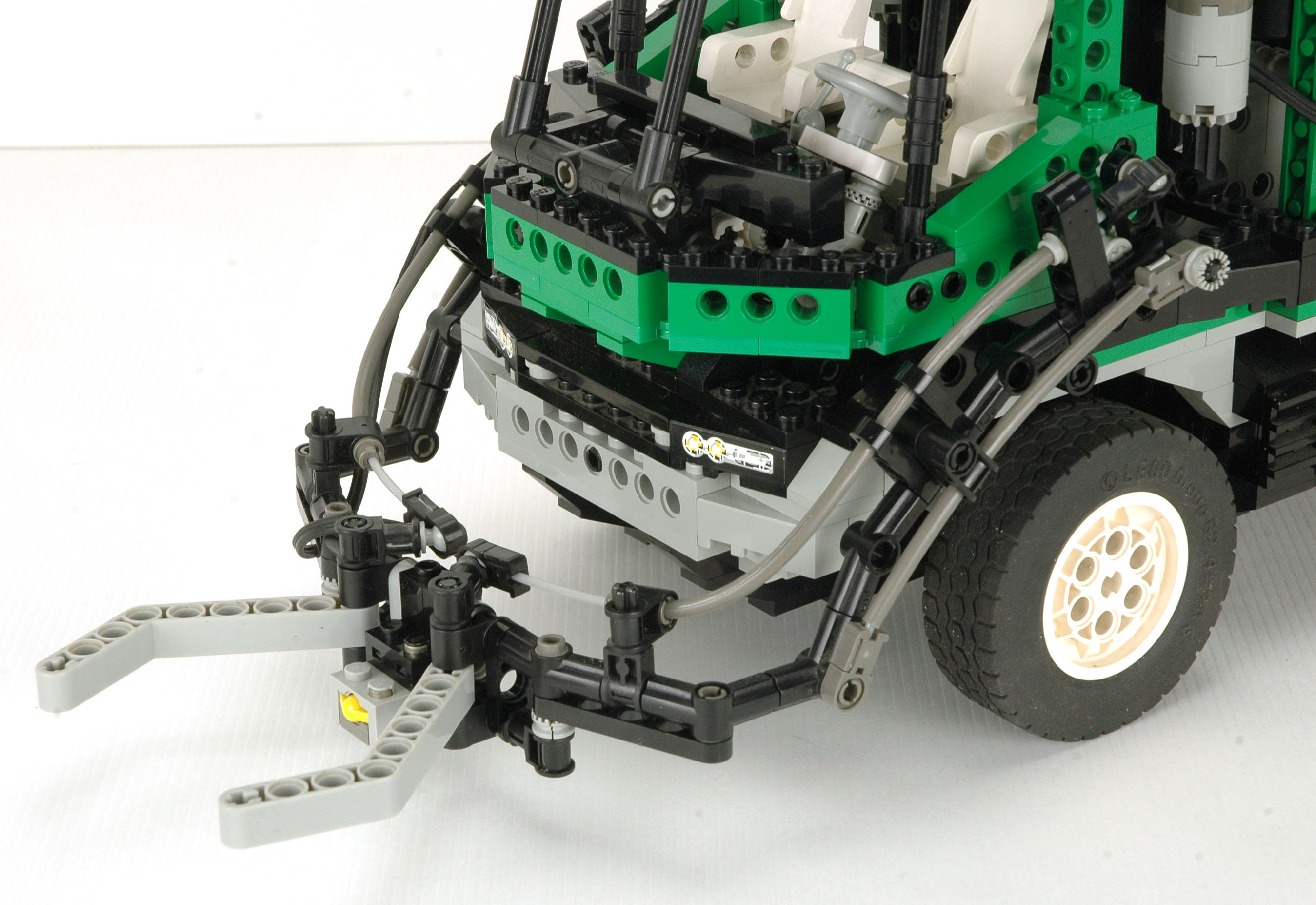
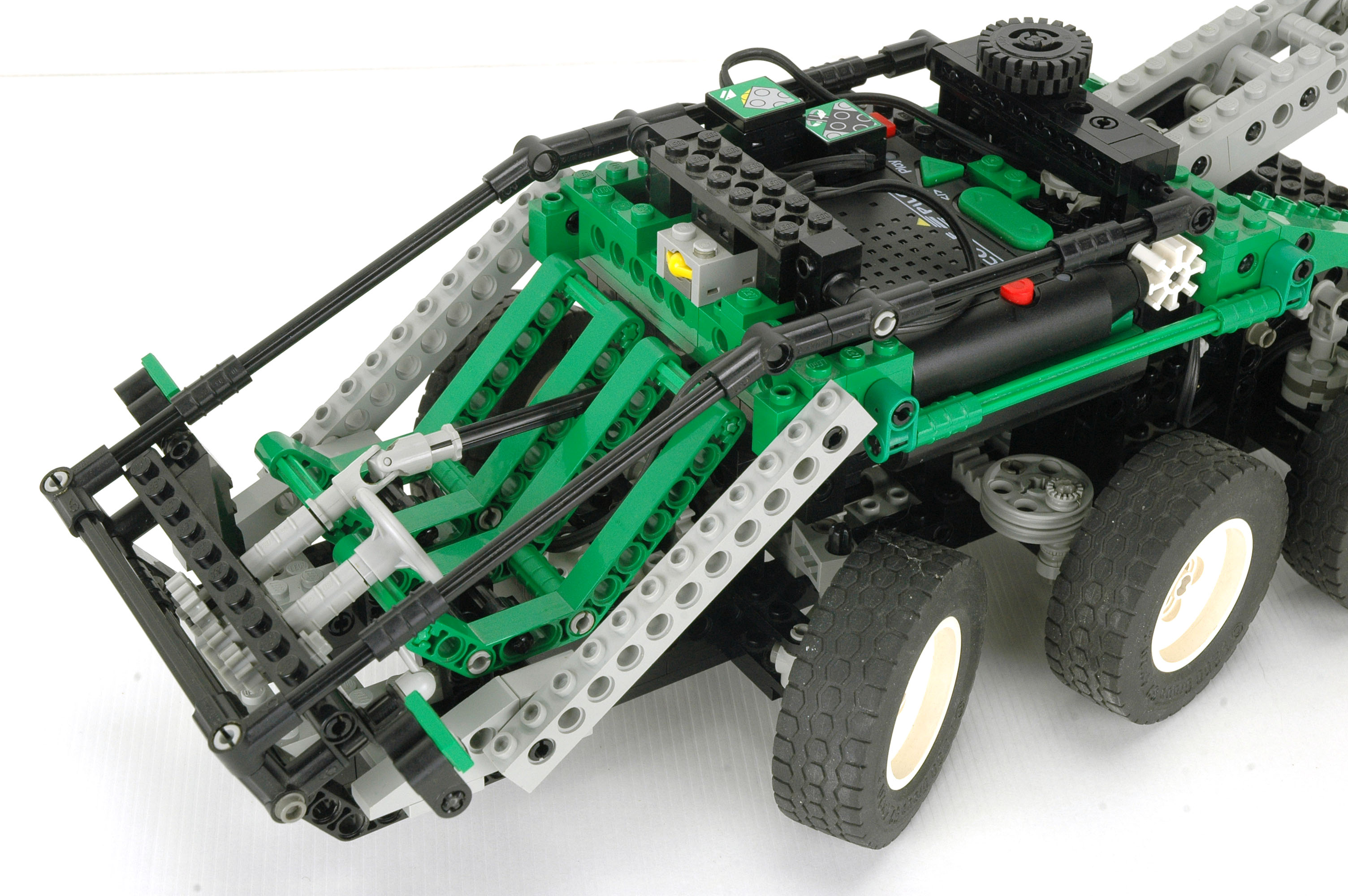
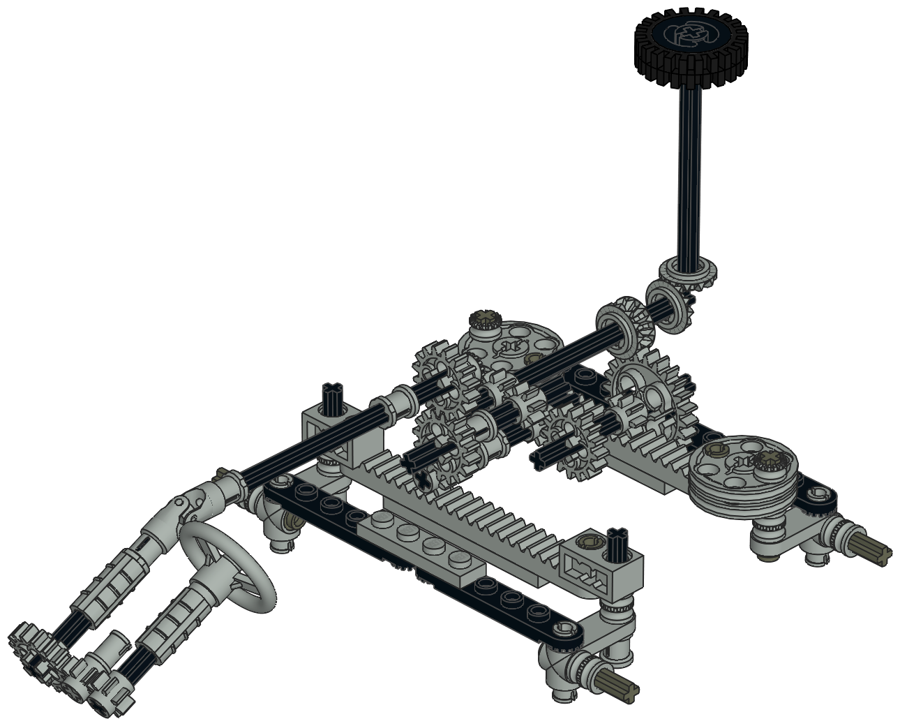
Steering
The front wheels can be steered with a marvelous rack and pinion
system. The rack uses Ackerman correction. You can see in
the images that the tie rod
attachments are not directly behind the kingpins, but are one stud
inboard. The result of this is that the wheel on the inside of
the turn is rotated more sharply than the wheel on the outside, which
is exactly what is required for a turning in a proper circle without
skidding.
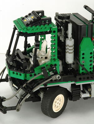
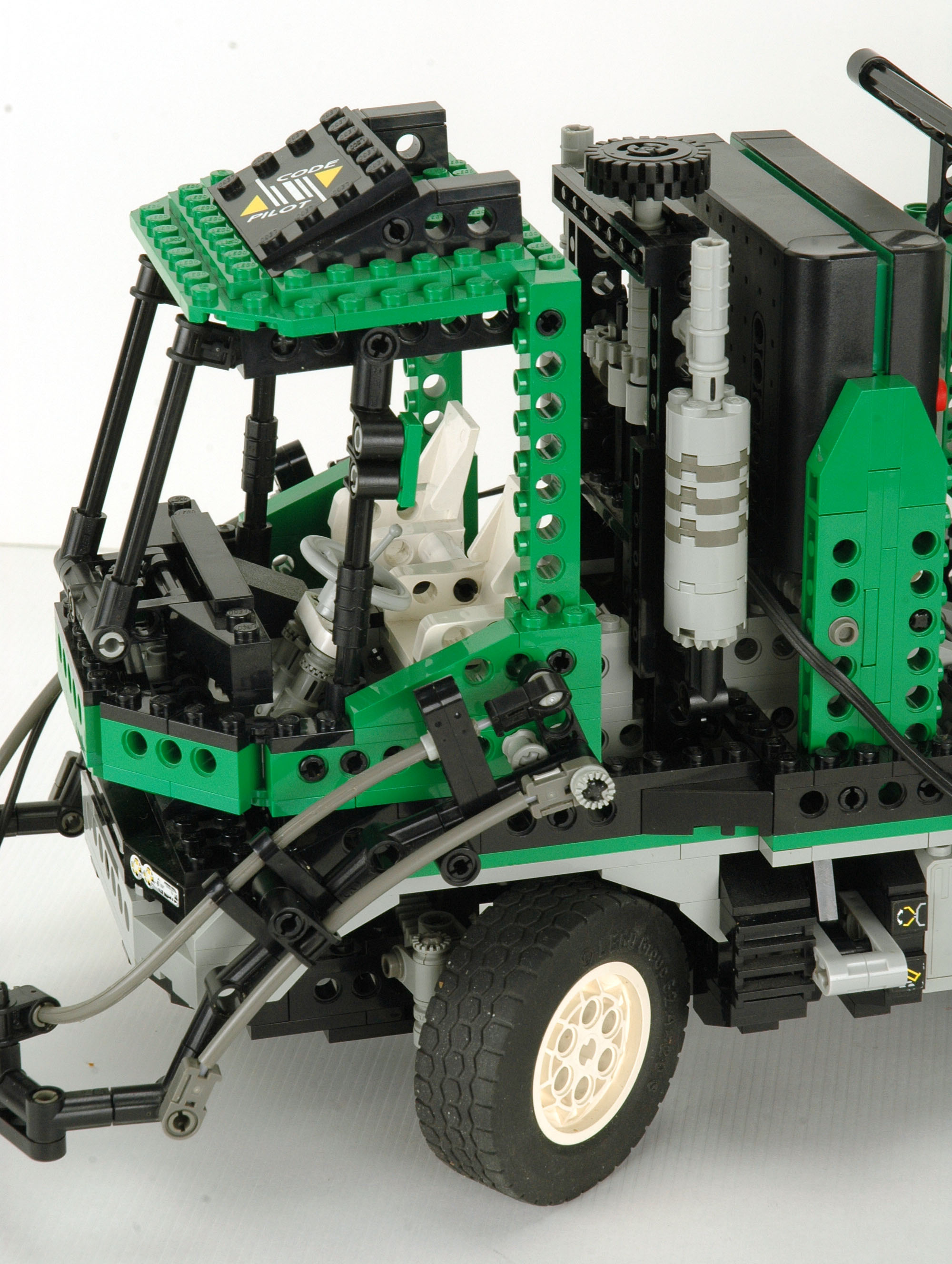
The steering is controlled via an overhead "Hand of God" input, but also
turns the steering wheel in the cabin. The cabin wheel even tilts
to different angles. The cabin itself is pretty well detailed
with seats, a shift lever, and an instrument panel.
|
Click for an animation of
the steering in motion. |
2nd
Model: Space Car
|
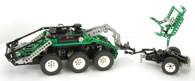
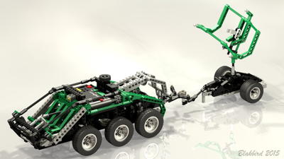
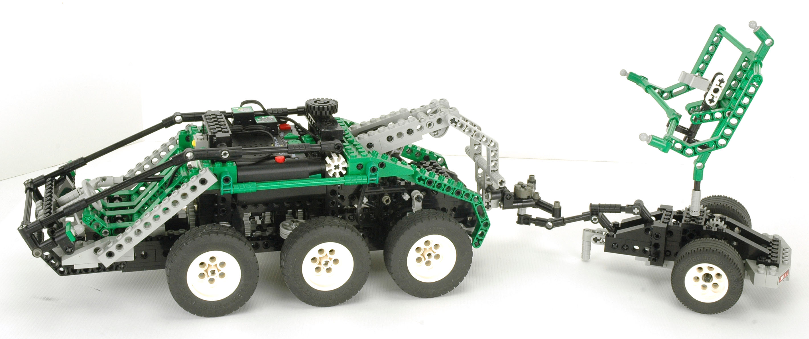
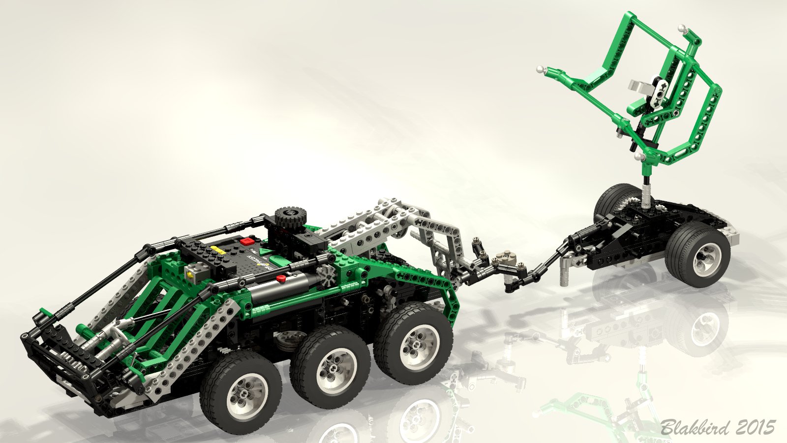
The
second model is a planetary exploration vehicle of some sort, complete
with towed radar or communication station. It includes 4 wheel
steering (shown in blue), speed based sound driven through a differential (shown in orange), a motorized tow arm which raises and lowers the trailer tongue (shown in red), and a rotating antenna.
When the program is run, the Code Pilot makes the sound of an
idling diesel engine. The trailer has a ratchet on the axle to
prevent it from rolling backward when disconnected. When the
vehicle is backed against the trailer, the tow arm contacts the rear
sensor. A rushing air sound is heard and then the engine sound
races up to a higher pitch and the tow arm lifts the trailer
tongue. This runs for a preset period of time and then the engine
returns to idle. Touching the sensor on the front causes the same routine to put the trailer back down.
When driving forward or backward, the timing wheel causes the pitch of
the engine to change. The motor can be moved to the back of the
vehicle to power the wheels instead of the arm, but this is not controlled by the program.
|
Click
to download the LDraw
file of this model.
Model by D3K
|
|
Electrical
The electrical system of this model includes both switches, the motor,
and Code Pilot. One switch is on the back of the vehicle and is
actuated by contact with the tow arm. The other switch is operated
manually and is above the driver's cabin.
Although this model has two switches, both switches go to the same port
so there is no way for the Code Pilot to distinguish between them.
The sequence alternates between driving the tow arm up and driving the
tow arm down. If it were to ever get out of sequence, the motor
would run against the stop and slip the clutch gear. This model
demonstrates the principle of programming the unit to alternate
different actions based on the same input.
|
 |
|
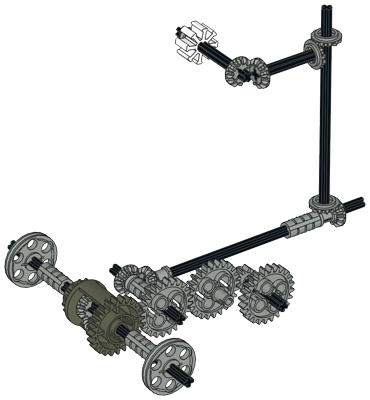
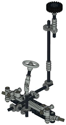
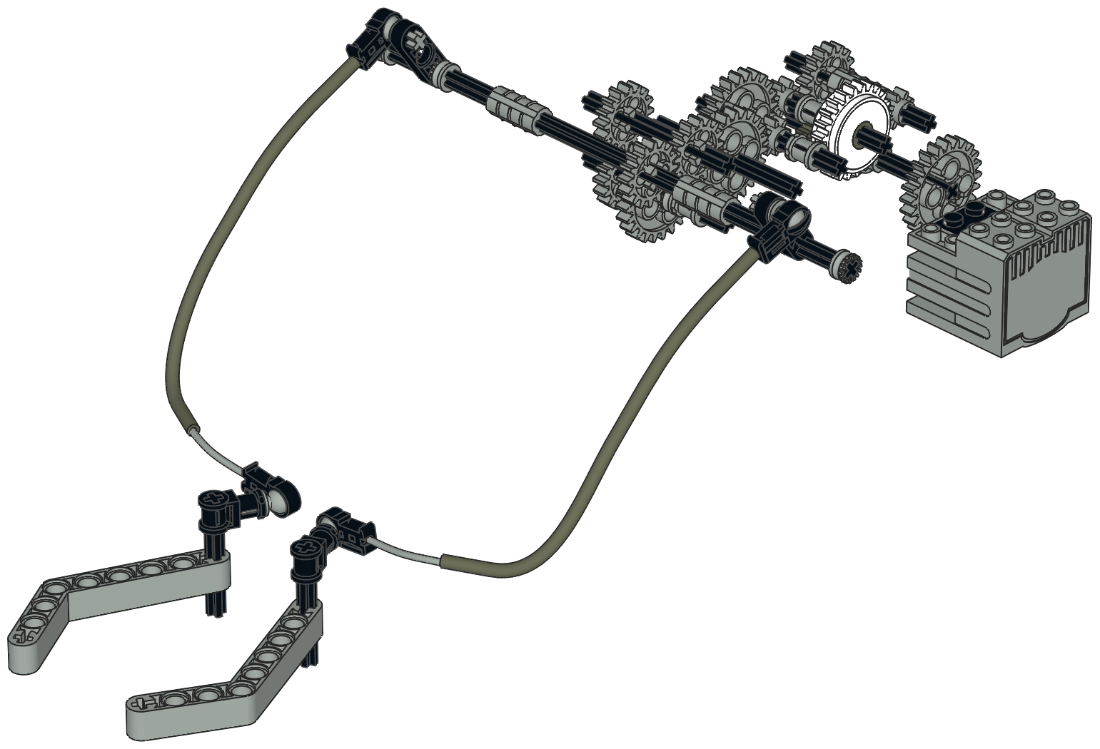
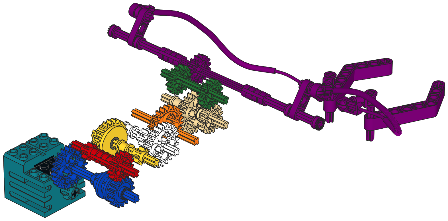
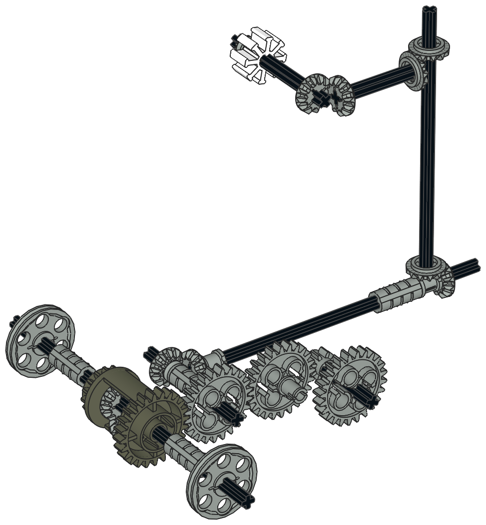
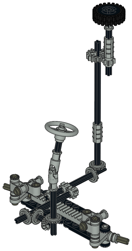
Steering
The 4 wheel rack and pinion steering is manually controlled by an
overhead "Hand of God" wheel, but also rotates a steering wheel at the
driver's position. As can be seen in the computer image, this gear
system uses an unusual gear pair of back-to-back bevel gears against a spur gear.
The front and rear steering racks use a different gear ratio and therefore turn at different rates to different lock angles.
|
Click for an animation of
the steering in motion. |
|
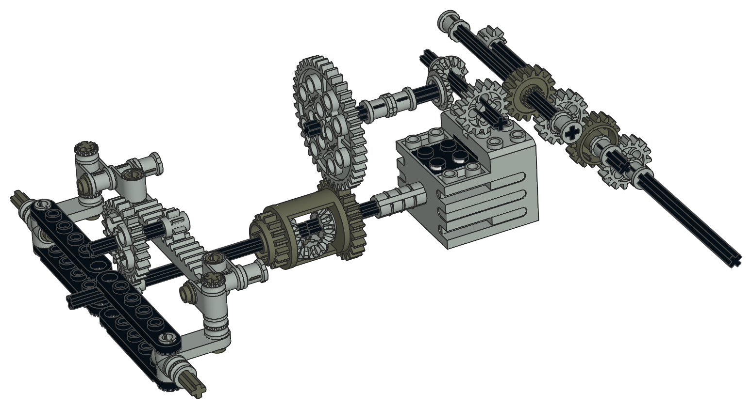
Drive Train
A differential between the rear wheels allows them to turn at different
rates. A spur gear connected to the differential ring gear runs
torque up to the timing wheel to allow the Code Pilot to vary the engine
pitch with speed. The bevel gears at the back of the computer
image are unused in normal operation, but connect to the motor if is is
optionally placed in the rear of the vehicle.
|

Click for an animation of
the drive train in motion. |
|
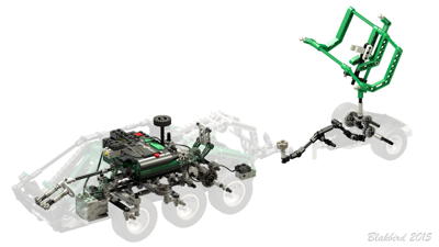
Towing Arm
The towing arm is motorized and geared down 243:1 via 5 stages of 3:1 reduction (3^5 = 243).
The black connector with half pin seen at the lower left of the towing
arm in the photograph contacts the touch sensor on the rear bumper when
the vehicle is backed into the trailer. This triggers the arm to
lift the trailer tongue. Touching the sensor again (or the other sensor) reverses the process.
The clutch gear in this system is designed to allow the arm to run into
the stops without stalling the motor. Since it is located 2
reduction stages from the load, a lot of force can still be put into the
stop. In fact, you can hear plastic creaking and groaning if the
system hits the stops. It would be better for the gear to be one stage further down.
|
Click for an animation of
the towing arm in motion. |
|
Communications Trailer
The interstellar communications dish is towed on a trailer. It rotates with the rear wheels at a 3:1 ratio.
The tongue of the trailer implements a clever ratchet system. When
the tongue is down, it connects to a pawl via a 4-bar linkage which
blocks the axle from turning. This allows the vehicle to back into
the trailer with enough force to actuate the touch sensor. Once
the tongue is lifted, the pawl pulls away from the ratchet and the axle turns freely.
Since the trailer has a solid axle, it does not turn very well. It
is also difficult to back because of the short wheelbase.
|

Click for an animation of
the trailer in motion. |
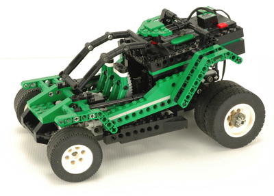
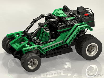
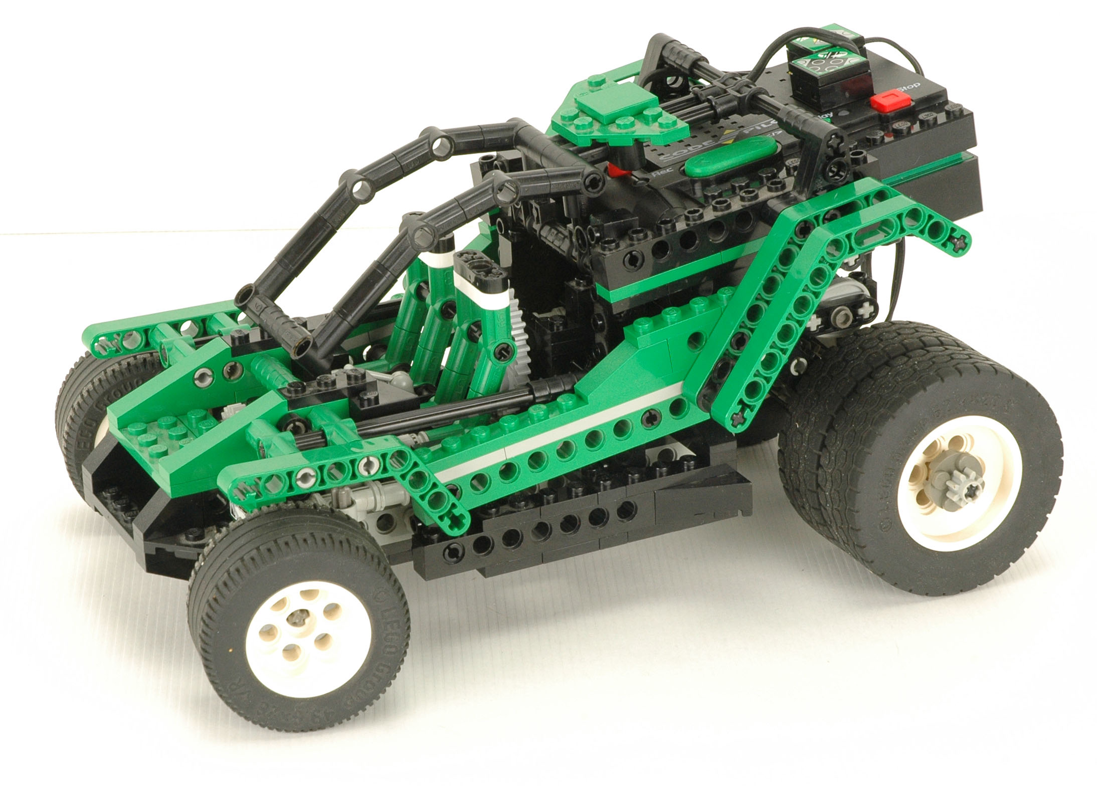
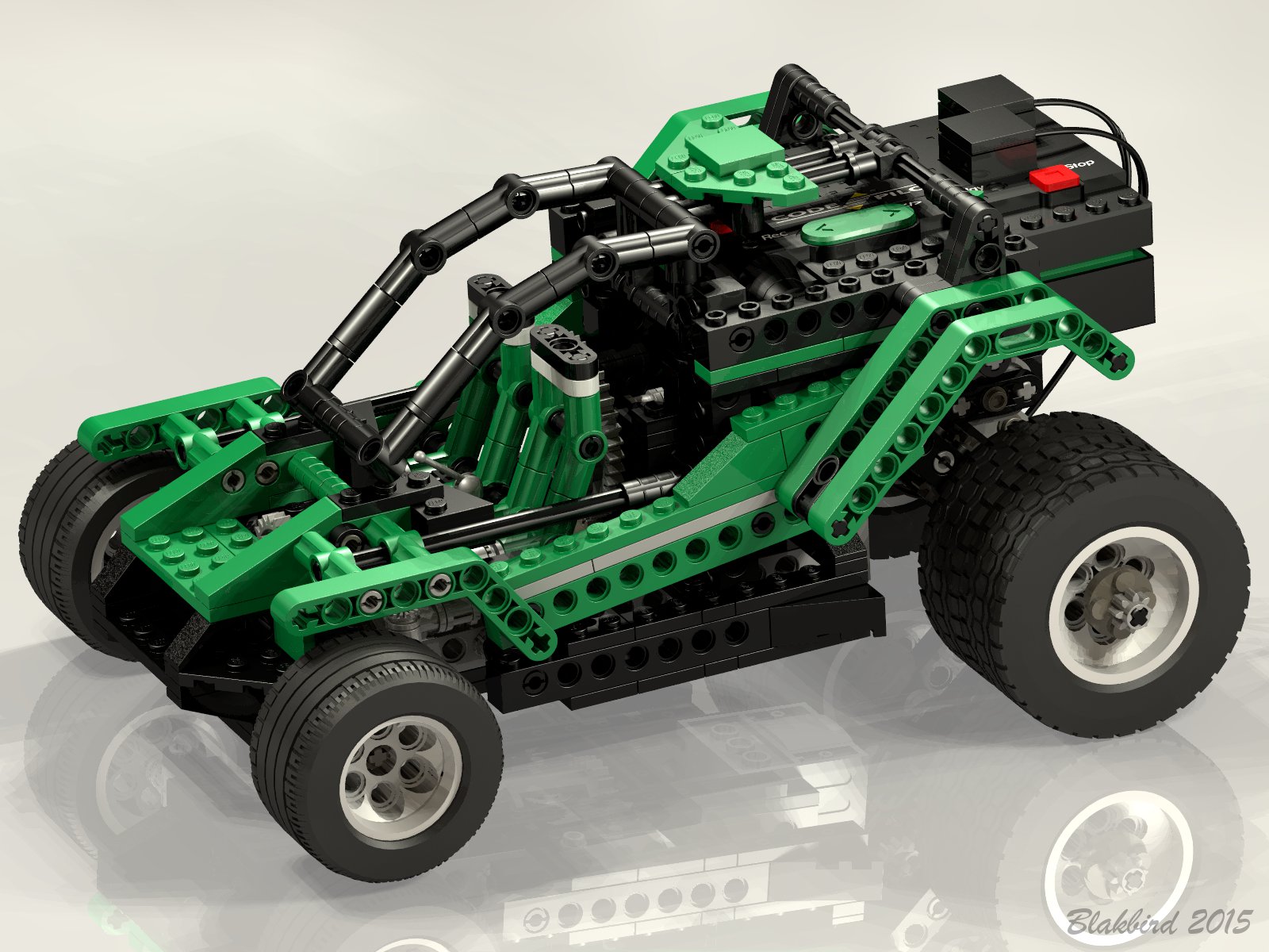
3rd
Model: Dune Buggy
|
The
third model is motorized dune buggy. While it looks quite simple
at first glance, this model is actually very clever and uses mechanical
techniques that do not appear in any other model.
When the program is run the model drives straight forward until it hits
an obstacle. The impact causes the rear suspension link to
compress very slightly striking the touch sensor. Once the sensor
state is switched, the motor's polarity is reversed and the car goes
backward. The really cool part is that the steering turns as the
car backs up causing it to change direction. A timer on this
function causes the car to back and turn about 120° before reverting to
forward motion and starting the program again. All of this could
be done in a modern Mindstorms set with a program, but
in this model it is all handled mechanically. It demonstrates the
capability to control multiple functions even with only a single motor
and sensor.
The model moves reasonably quickly and can handle carpet, but not uneven
ground. Surprisingly, it does not make use of the clutch gear so
the motor stalls when the model backs into something.
The car makes an annoying robotic beeping sound when moving forward and a
differently annoying sound when moving backward. The only way to
avoid the sounds is to encode a custom program. There is no volume
control on the Code Pilot.
This is the only model in the set that uses the 40 tooth gear. It is extra when the main model is built.
|

Click
to download the LDraw
file of this model.
Model by D3K
|
|
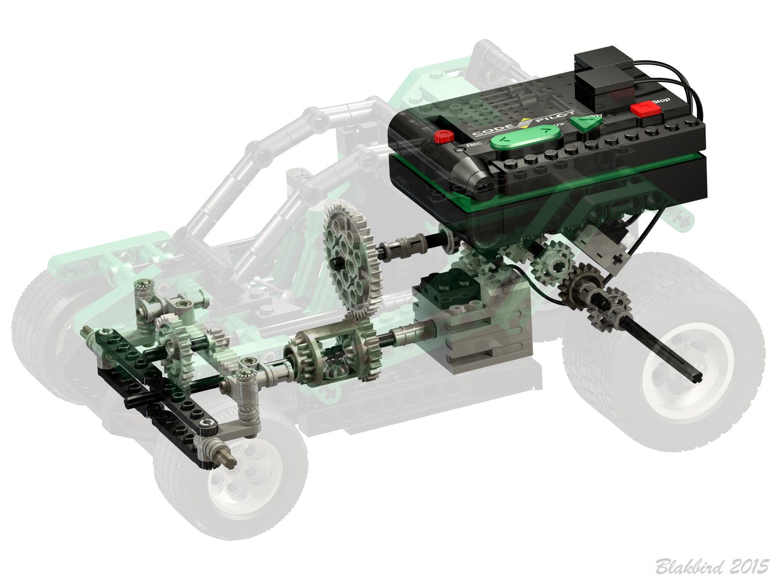
Electrical
The electrical wiring is very simple with a single switch wire (orange)
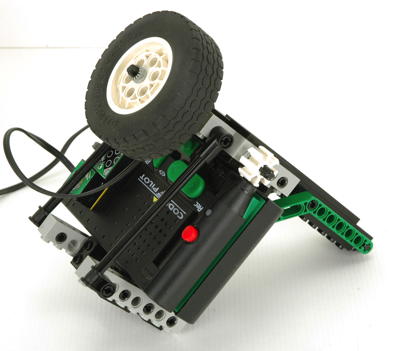
and a single motor wire (blue). The Code Pilot is housed on rails
right over the rear wheels and is easily removable. The motor is
not removable but is trapped once the model is built. The timing
wheel is not used on this model so the barcode reader does nothing when
the program is running.
|
 |
|
Drive Train
The key to this drive train is the differential. Although
differentials are most commonly used to allow the wheels on an axle to
turn at different speeds, what they really do at the core is equalize
torque. As seen in the computer image, the motor drives one pinion
gear of the differential. The other pinion gear goes to the
steering, and the housing ring gear goes to the left rear wheel (right
wheel is not powered). The steering linkage is built so that it is
blocked from turning left and can only turn right. When power is
applied in the forward direction, the steering cannot turn so all motion
goes to the drive wheels. When power is applied in the backward
direction, the steering moves into the right turn stop first because
that circuit has less resistance than the drive wheels. Once the
stop is encountered, the car starts to back up. In either case,
the steering stop has to react an amount of torque equal to that being
applied to the drive wheels.
|
|
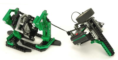
4th
Model: Robot
|
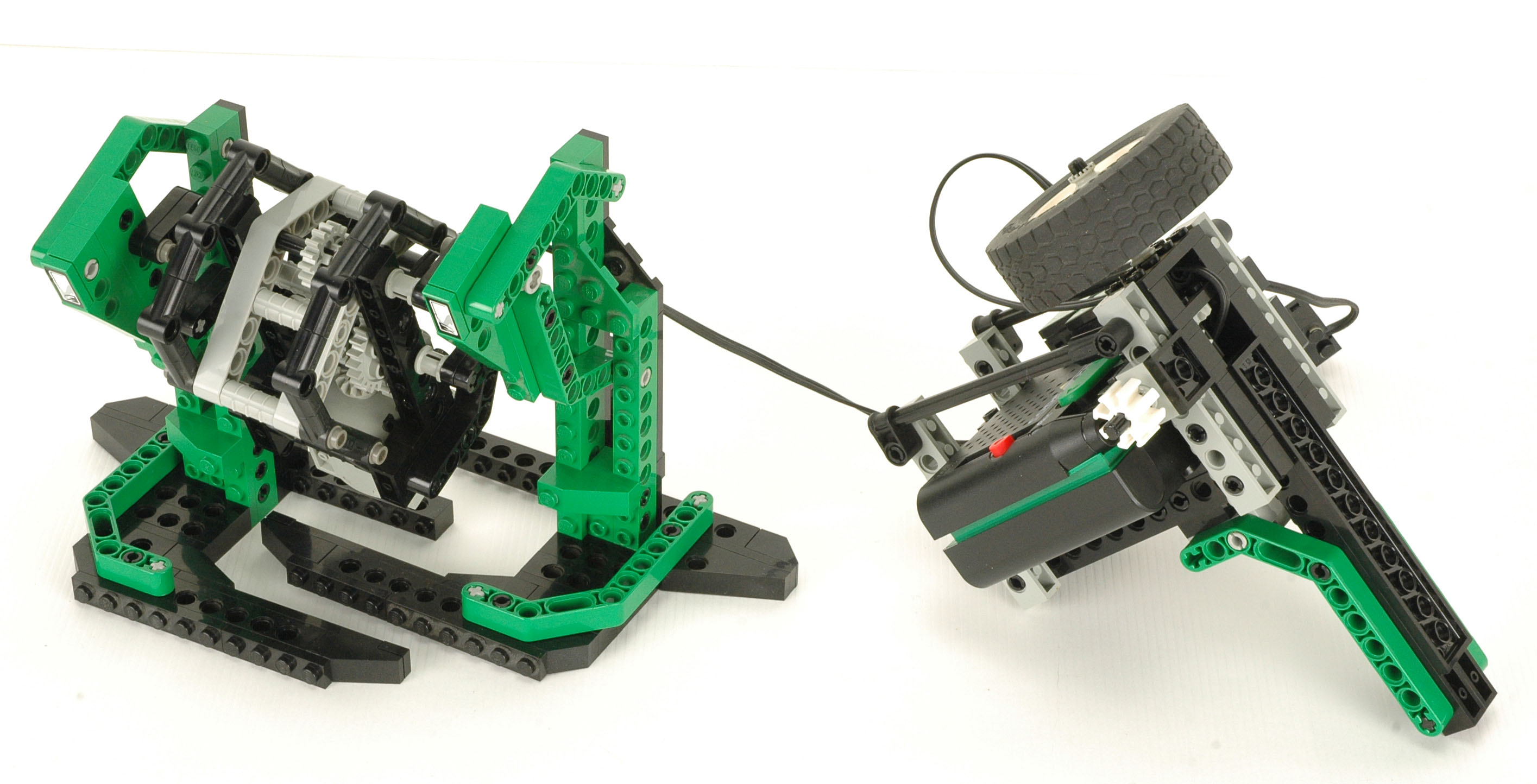
The
4th model is bi-pedal robot walker with a pistol grip controller. Unlike previous attempts
at making a motorized walking robot with Technic, this one actually
works! It can walk either forward or backward at varying speeds,
but no turns are possible. Rotation of the wheel atop the
controller causes the robot to walk forward. In theory, different
rotation rates should result in different walking speeds, but in
practice the motor does not have enough power and the lower speeds to
move the robot. Holding the "trigger" switch makes the robot walk
backwards. It does not matter which direction you rotate the
wheel, the walking direction of the robot is only related to the state of the switch.
The robot is tethered to the controller with a single wire. The
wire is not very long so the operator must remain quite close to the
robot.
The default program for this model uses an annoying beeping sound that
sounds like it is from an old Atari game. Possibly Space Invaders.
This model demonstrates the capability of controlling the speed of the
motor using the timing wheel. It is the only model that does so.
|
Click
to download the LDraw
file of this model.
Model by D3K
|
|
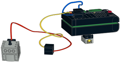
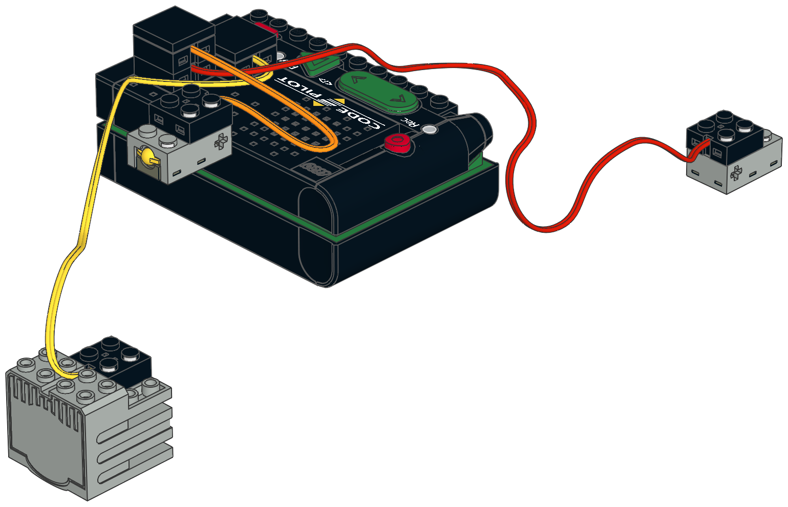
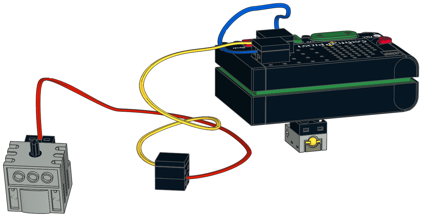
Electrical
The electrical system is about as simple as is possible for the Code
Pilot. The Code Pilot is housed on the remote along with a single
switch used for switching from forward to reverse (connected with blue wire). Two wires (red and yellow) are connected in series to tether to the robot.
|
|
|
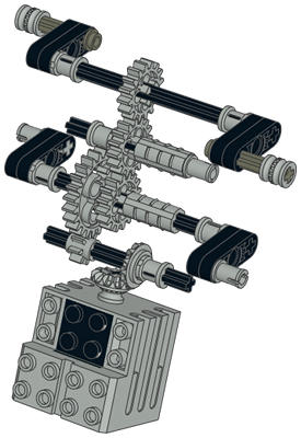
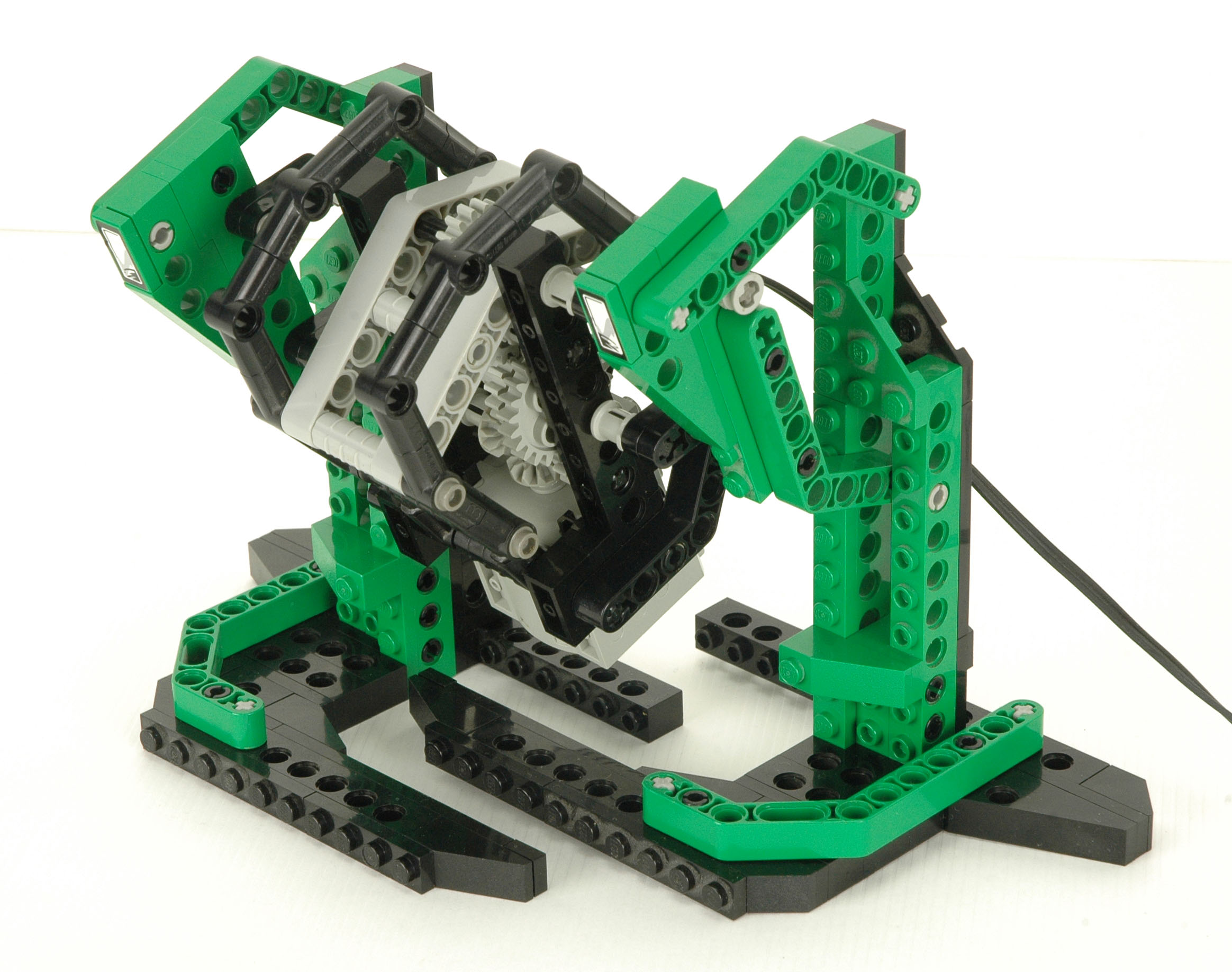
Robot
The key to the stability of this robot is that fact that either leg by itself is large
enough to support the whole thing so no complex balancing is
required. This is possible because the feet pass under the robot's
center of gravity.
As shown in the computer image, the walking mechanism is a simple 4-bar
parallel linkage driven at the black cranks. The left and right
legs are 180° out of phase. The motor is geared down 3:1 at a
single stage; the other stages are 1:1. This results in a robot
that walks very quickly. It would actually be preferable if it was
geared down further.
|
Click for an animation of
the robot in motion. |
|
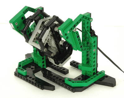
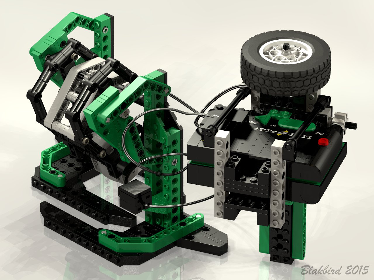
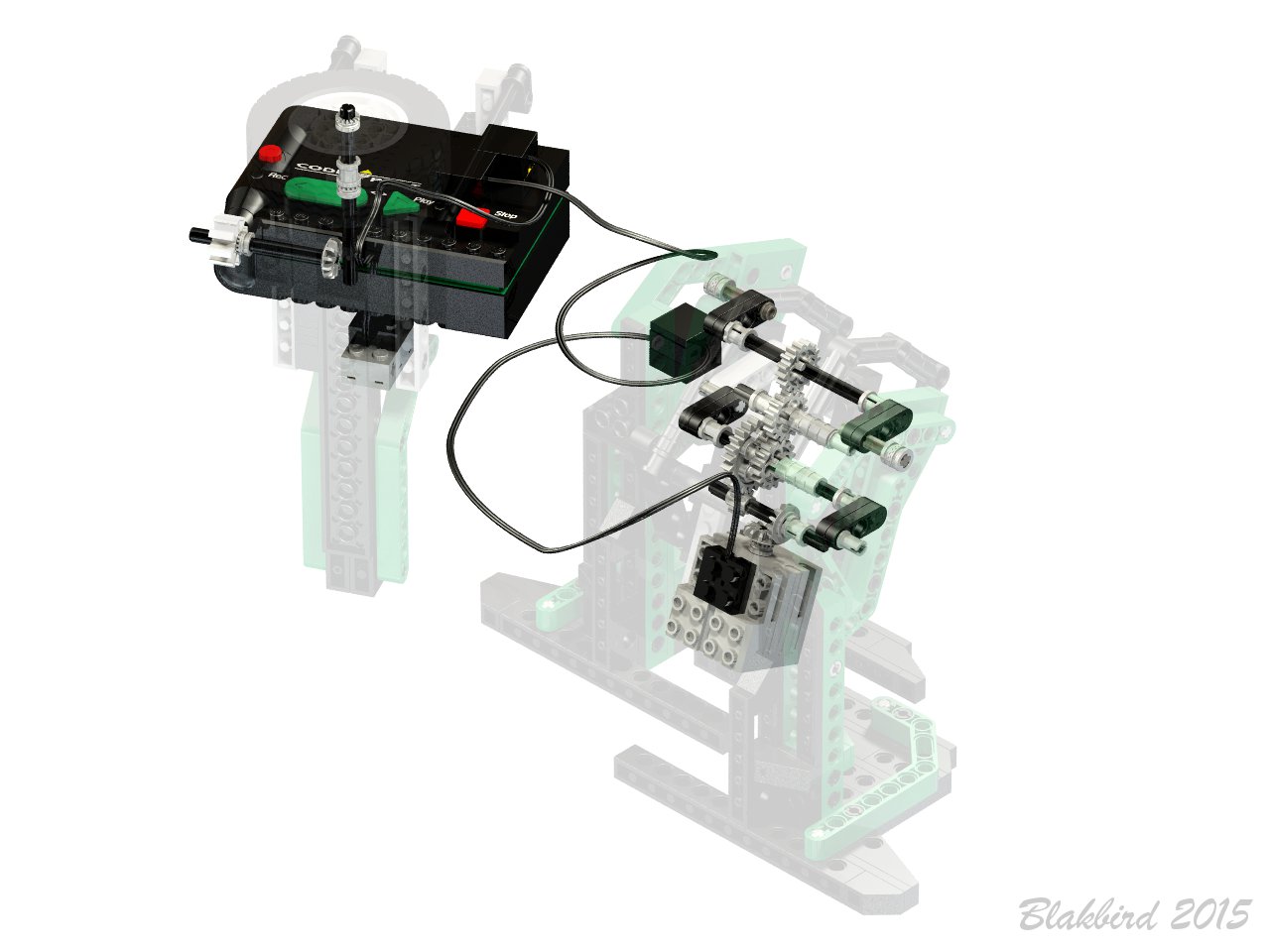
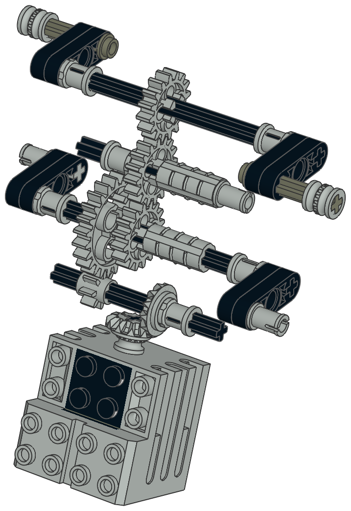
Controller
The pistol grip controller houses the Code Pilot. Rotation of the
wheel on the top drives the timing wheel as shown in the computer
image. When the barcode reader senses rotation of the timing
wheel, it sends power to the motor at a level proportional to the speed
of the wheel. In practice, only max speed with make the robot move
since there is insufficient power at lower speeds. This suggests
that the control center regulates speed by simply dropping
voltage. Depression of the trigger switch causes the robot to walk backward (reversed polarity on the motor).
Note that the wheel must be rotated to continually; the robot will not
keep walking once started. This makes it rather cumbersome to
control for more than a couple of seconds.
|
  |


