Features
|
|
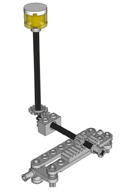
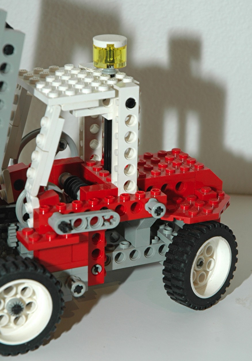
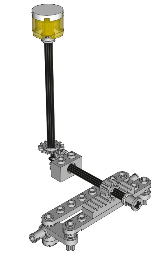
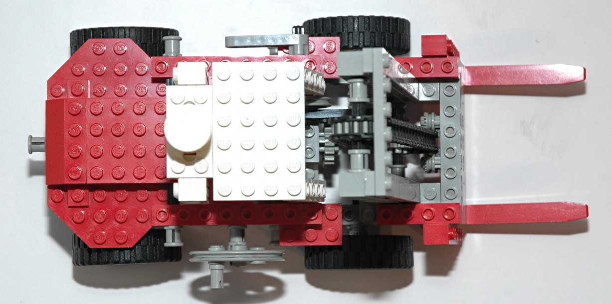
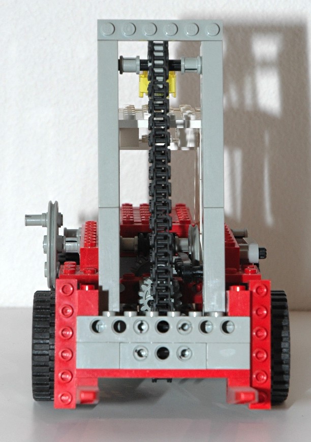
Steering
The rear wheels can be steered using an overhead "hand of god" control. The overhead control drives
an axle connected to
a pair of 14 tooth bevel gears. The second axle drives a
rack via an 8
tooth pinion
gear. The steering mechanism itself uses the steering arms
and toothed links as shown in the computer image.
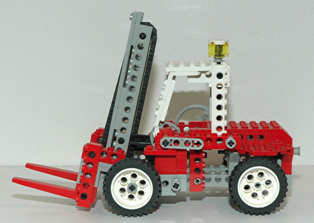
The steering knob is designed to look like a flashing light.
|

Click for an animation of the
steering in motion.
|
|
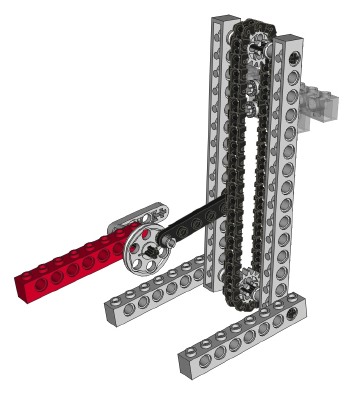
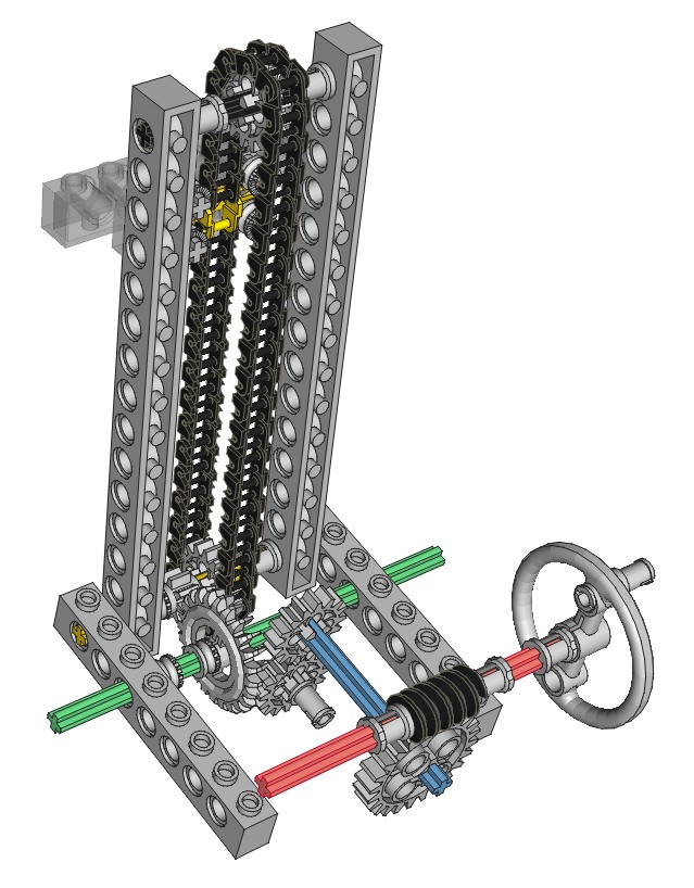
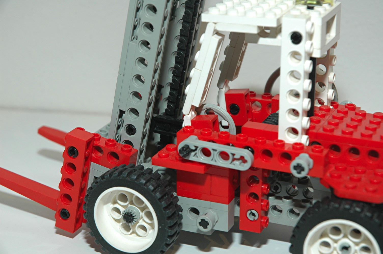
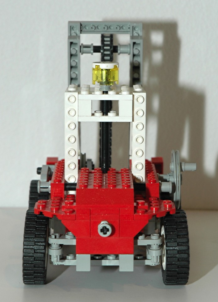
Forks
The forks can be raised and lowered via a crank of the right
side. The computer image is color coded to follow the path of
torque. The input crank turns an axle (red) with a worm
gear. A 24 tooth spur gear (blue axle) is driven by this.
Torque passes through a set of 16 tooth spur gears and into a 24 tooth
crown (green axle). The crown drives an 8 tooth pinion which is
connected to the axle driving the lift chain. The lift chain
stretches across the frame between two 16 tooth gears and has one wide
link (yellow). This link lifts the forks.
The final gear ratio is 12:1. The worm gear prevents the system
from backdriving because the axial friction is higher than the
backdriving torque due to the screw pitch angle.
The moment created by the cantilevered weight is
reacted by a force couple: the upper forward load is reacted by a
set of 2x2 corner plates on the back of the vertical fork assembly, and
the
lower aft load is reacted by contact of the
lower tiles against the vertical fork assembly. This system fits
a bit too snugly and tends to jam.
|

Click for an animation of the forks
lifting.
|
|
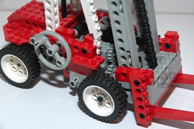
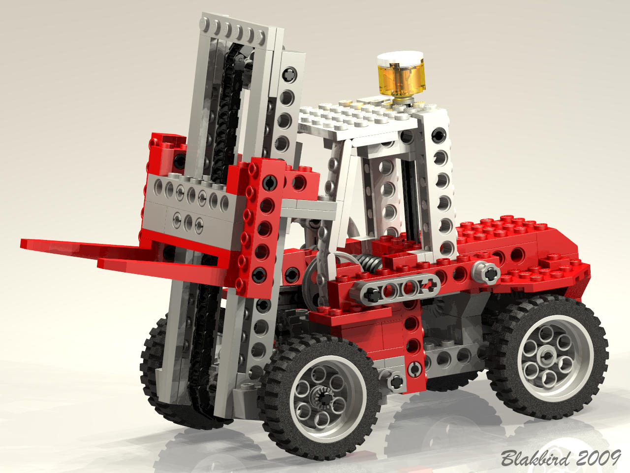
Fork Tilting
The entire fork and lift assembly can also be tipped forward to aid in
picking up a pallet from the ground. A lever on the left side
made of a new liftarm
turns a pulley wheel used as a crank. A link
attached to the crank connects to the vertical structural assembly
which
pivots about an axle on its base. Because the link travels over
center on the pulley wheel, weight on the forks will not tip the
mechanism when locked (see animation).
|

Click for an animation of the forks
tilting.
|
|
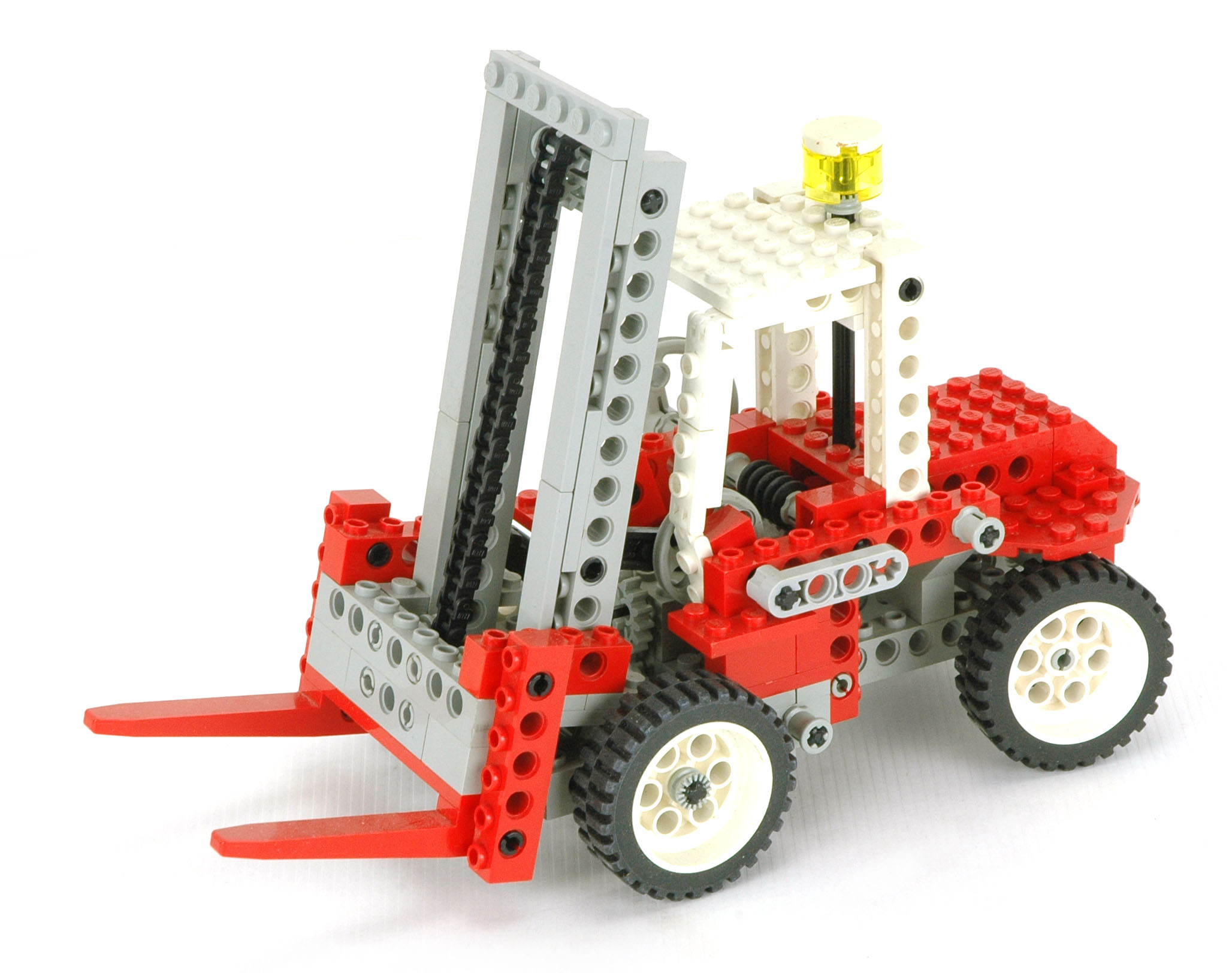
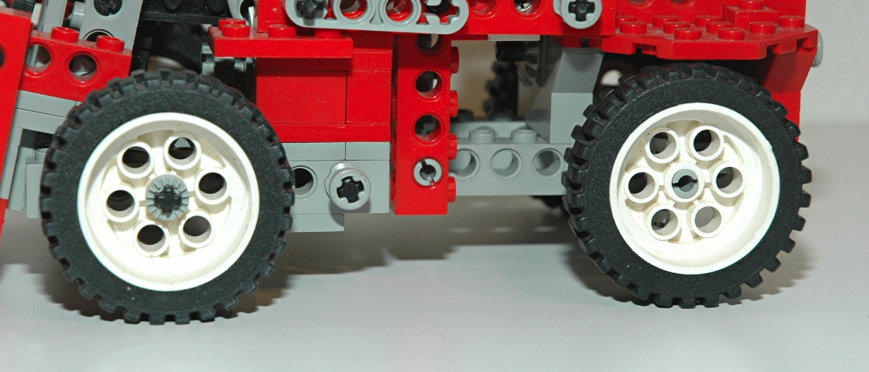
Wheels and Tires
This set has 4 of the 13x24 Model Team wheels. |

|

