|
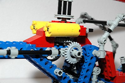
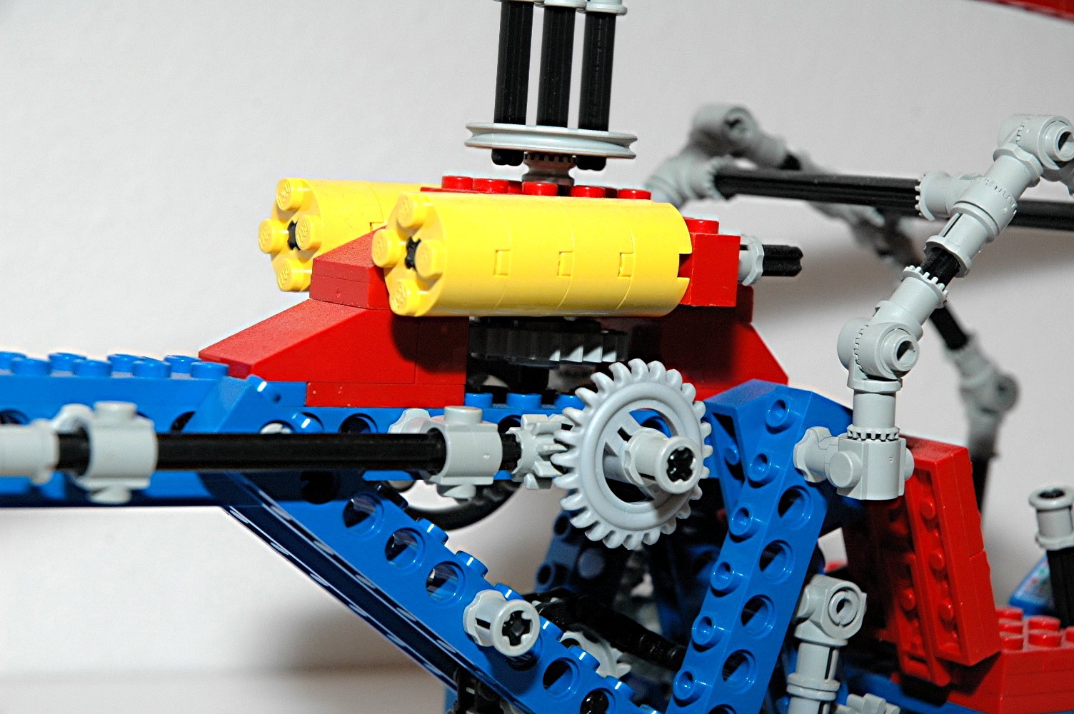
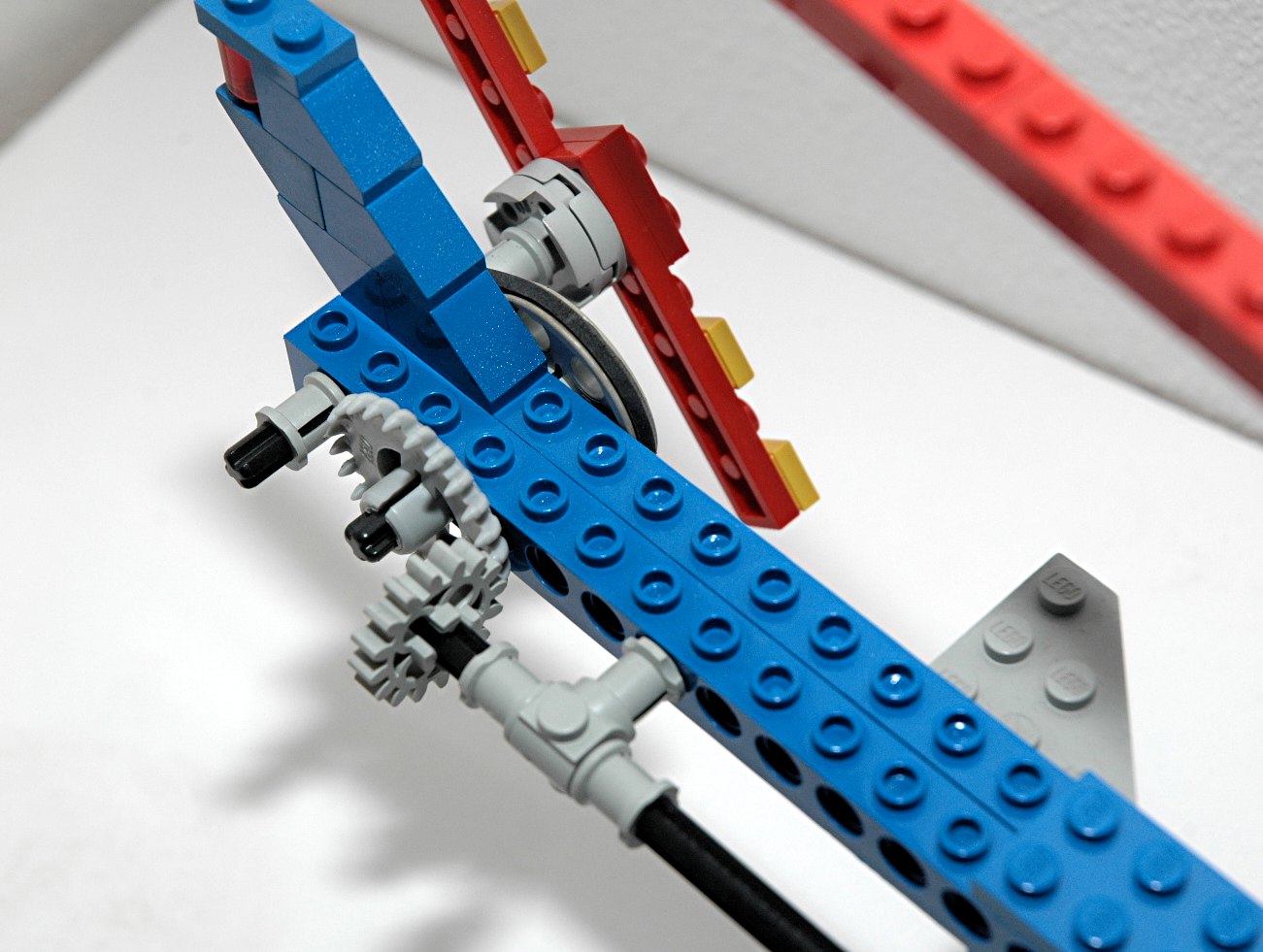
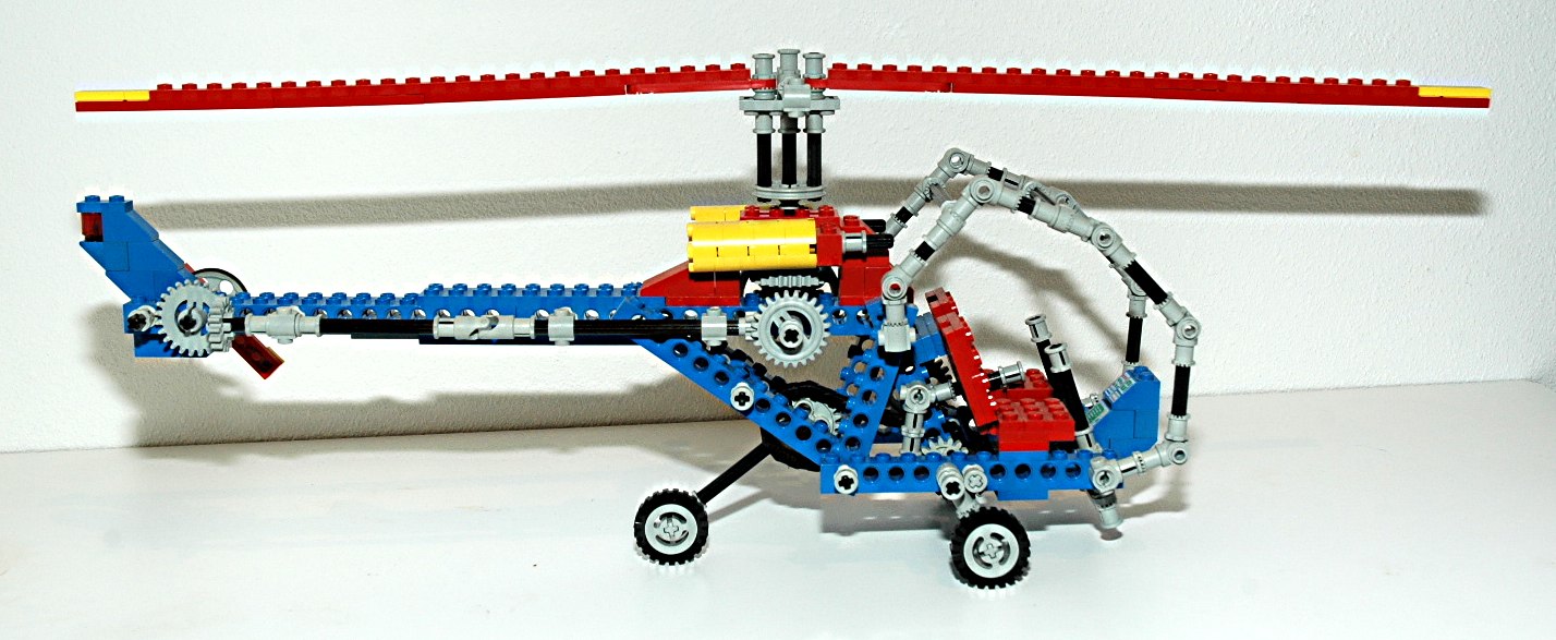
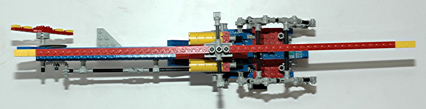
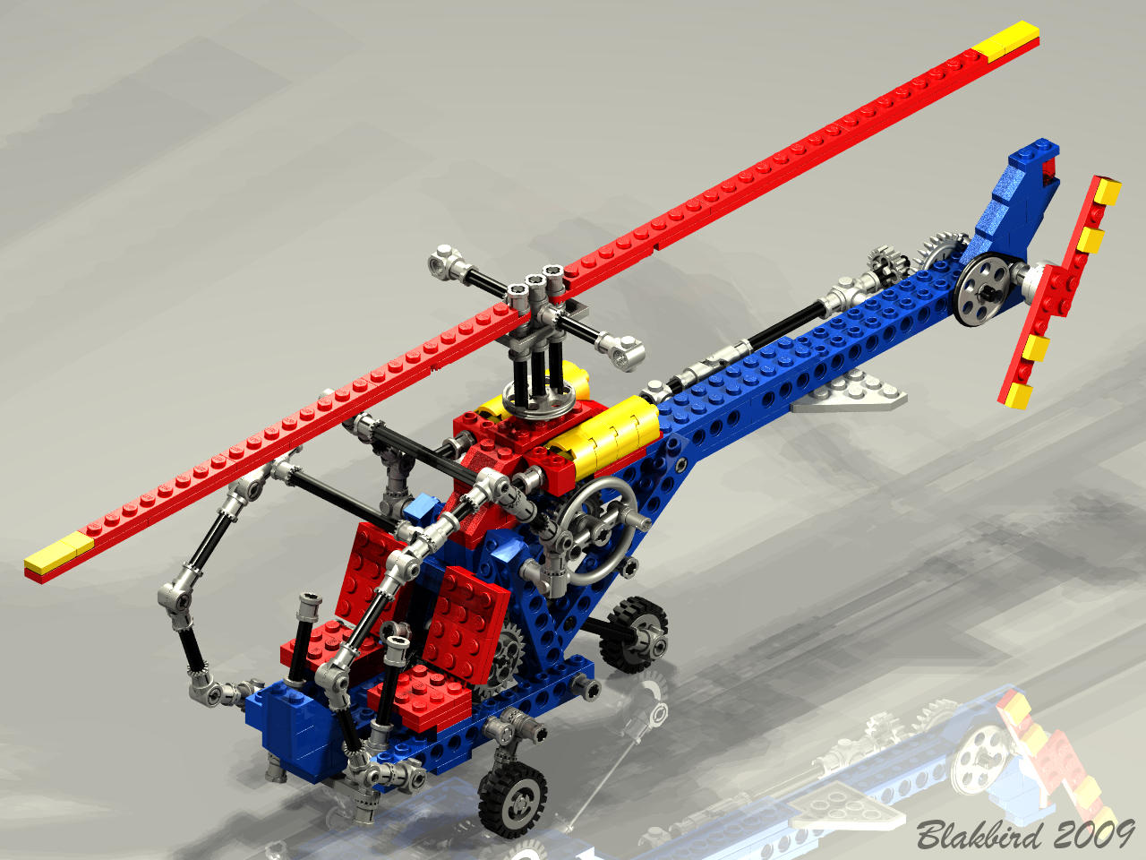
Rotors
The rotors' rotation is driven by an input crank on the left
side. This crank drives a set of 24 tooth gears giving the main
rotor a ratio of 1:1. The crank axle also drives a set of 24 and
8 tooth gears which passes torque along the length of the boom to the
tail. Here another set of gears, this time 24:16 passes torque
through the frame where the final transfer is made through a
belt. The ratio of the belt can be calculated based on the ratio
of the pulley circumferences (or diameters) which is about 3:1.
The final ratio of the tail rotor is 4.5:1 which makes for a fast
moving tail. Because of the limited frame rate of the animation,
the tail rotor looks like it is skipping rather than rotating.
The main rotor head has parts which make it look like a Bell-Hiller
mechanism is present to drive the paddles, but it does not actually do
anything.
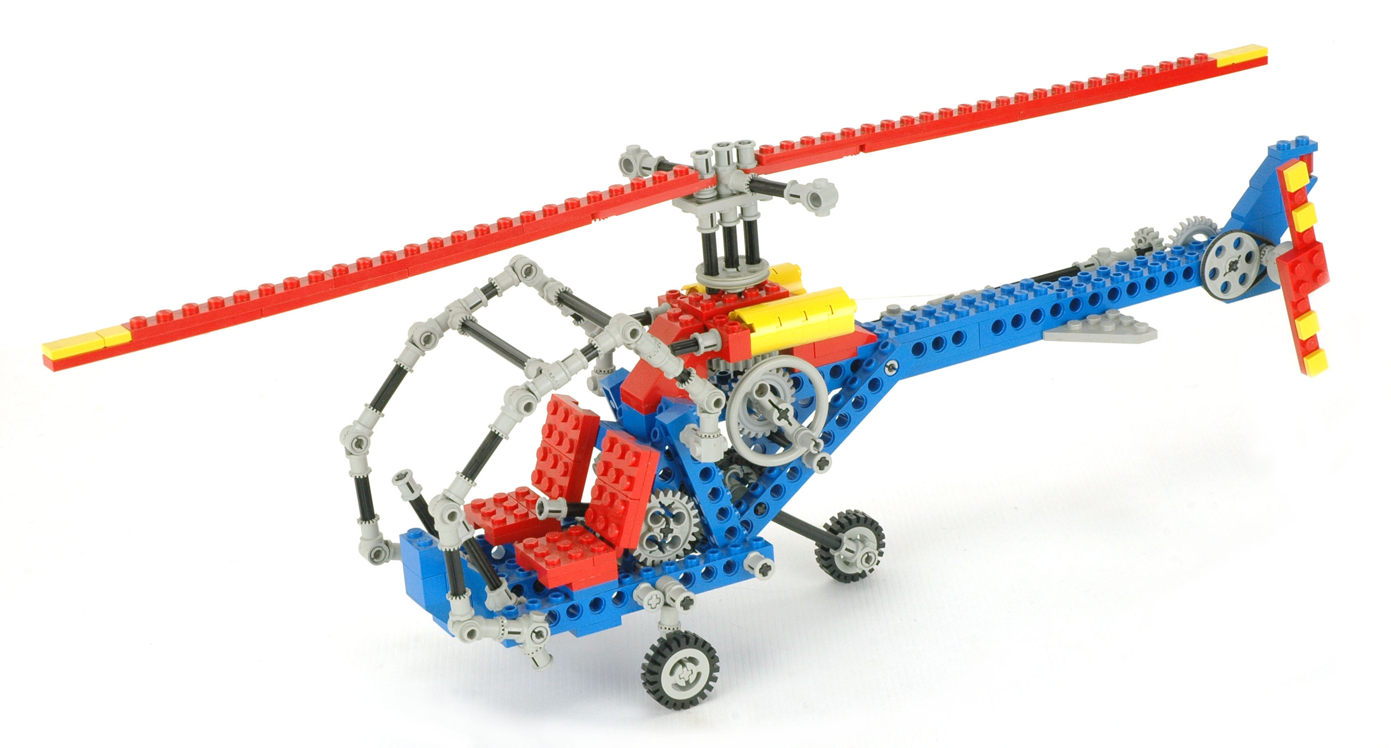
Both the main and tail rotors are twin blade and are constructed from
standard plates.
A pair of simulated turbine engines are nestled beneath the main rotor
head.
|
Click for an animation of the rotor
in
motion.
|
|
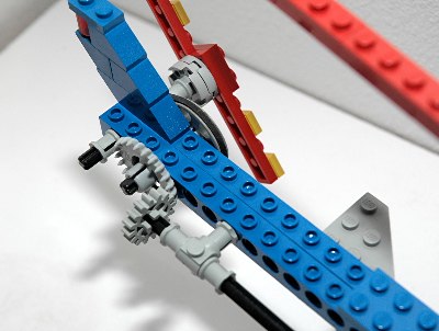
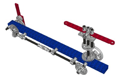
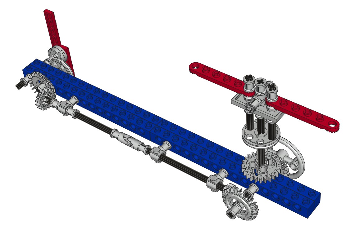
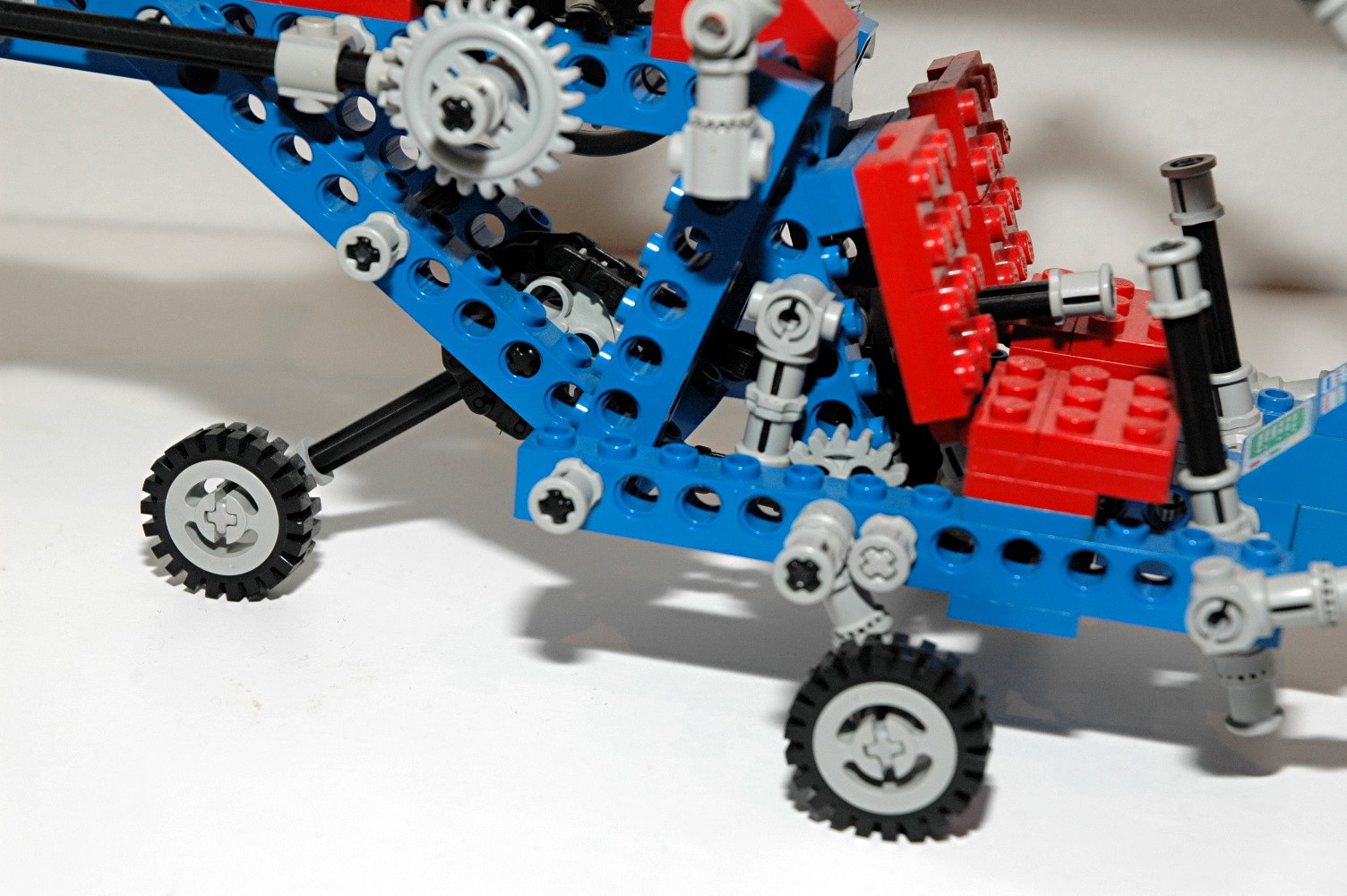
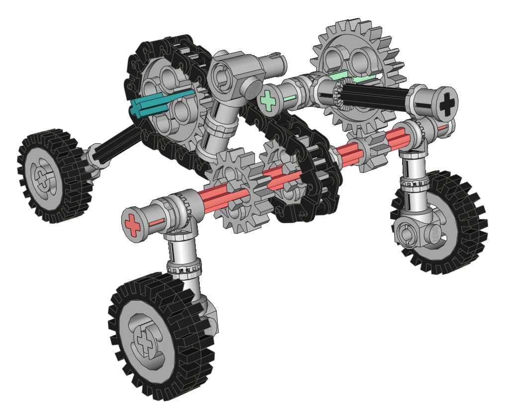
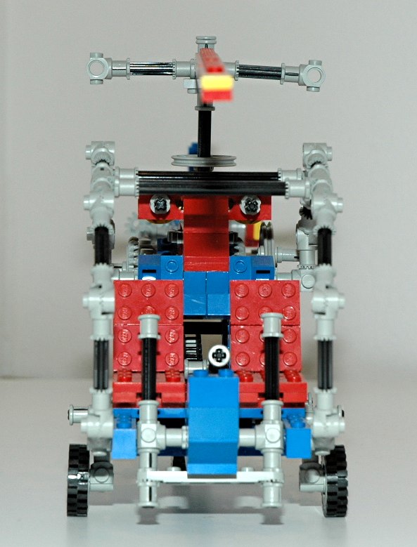
Skids
The 3 point landing gear retracts via a very tricky little
mechanism. See the color coded computer image to follow the
explanation.
A lever between the pilots' chairs drives the motion. This lever
(attached to the green axle) drives a set of 24 and 8 tooth gears to
rotate the red axle. The red axle is attached to the two forward
gear. The 3:1 ratio means that the lever doesn't have to move much to
rotate the gear the approximately 110 degrees between UP and
DOWN. A 16 tooth gear on the red axle mates with a pawl and acts
as a ratchet not to hold the gear up, but to hold it down.
Without it, the tail collapses and backdrives the mechanism.
Another 16 tooth gear on the red axle drives a chain attached to a 24
tooth gear on the rear (blue) axle which is attached to the tail
gear. Because of the ratio difference, the tail gear rotates
through a different angle than the main gear.
This gear requires a very particular setting to rig. If you are
so much as one chain link off in setting the relative angles between
the tail and main gear, then the whole mechanism doesn't work right.
(Note: The yellow skids
the animation are not part of the set. They were used to support
the model during animation.)
|


Click for an animation of the landing
gear in
motion.
|