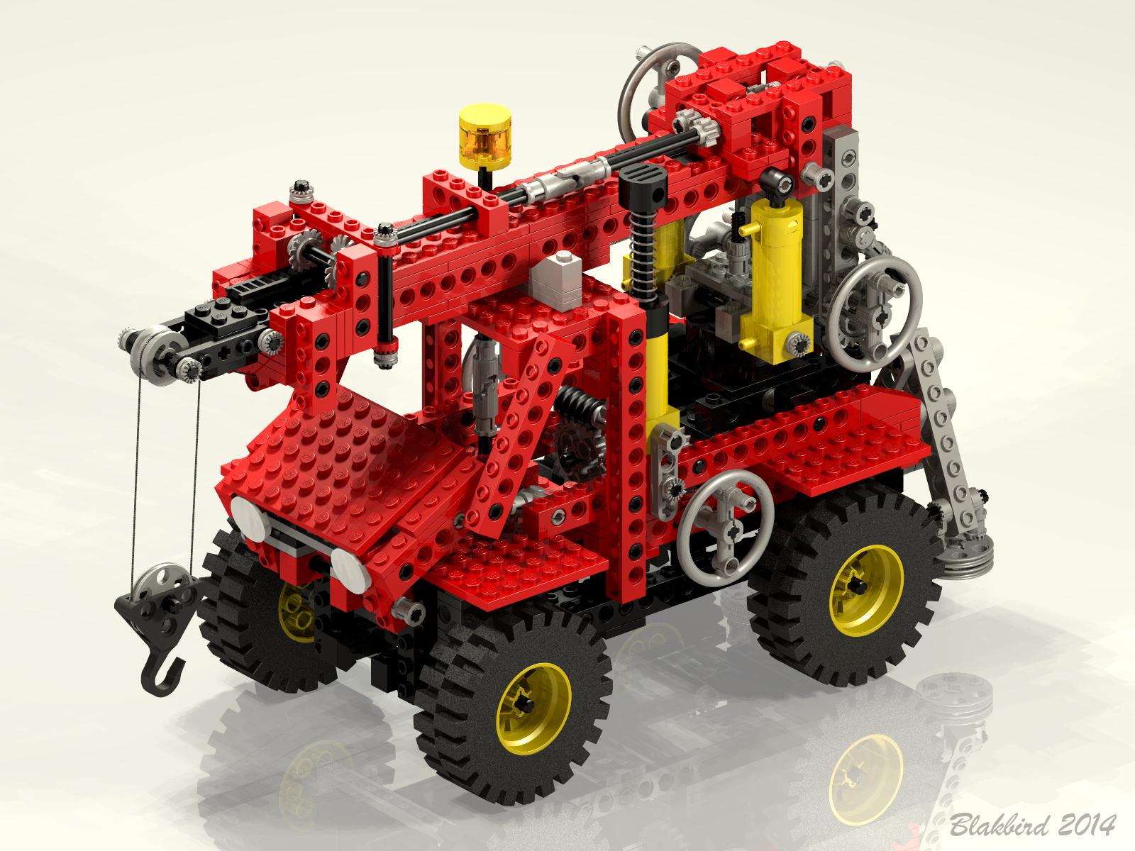
Features
|
|
Pneumatics
This model contains a double acting pneumatic system. The components of
this system are connected with rubber tubing routed through and around
the holes
in the beams.
A single pump provides air pressure. Depression of the piston
produces pressure. The pressure is fed to an inlet of a selector
valve (switch) with two outputs. Selection of the switch in
either direction allows pressure to flow to either chamber of the
actuators.
Finally, there are two pneumatic actuators which have ports at the
head and rod ends
to accept input from the switch. Head end pressure extends the
piston, while rod end pressure retracts it. This model uses a
pair of actuators in parallel connected via T fittings.
|
 |
|
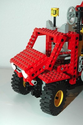
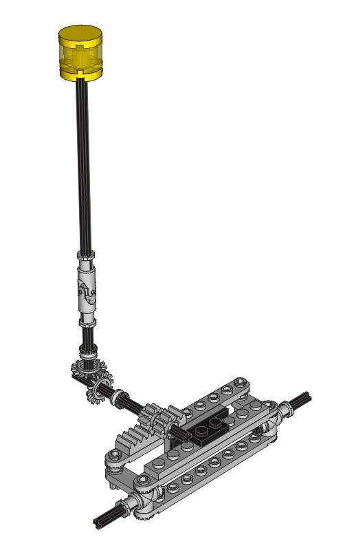
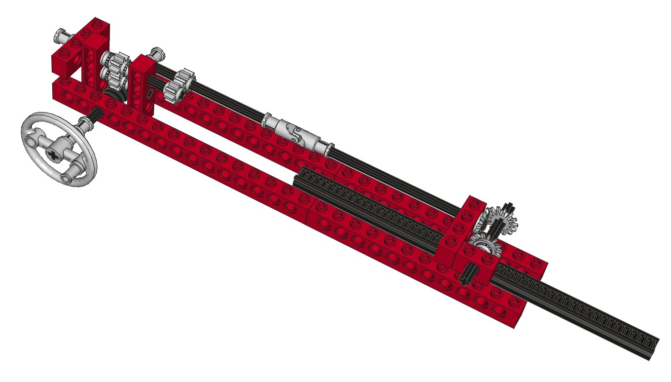
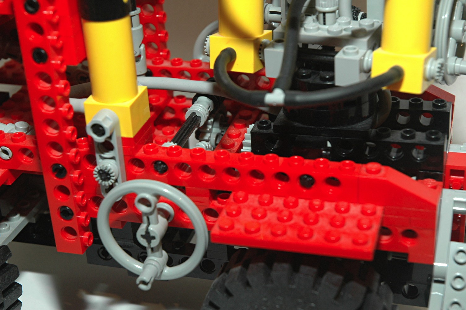
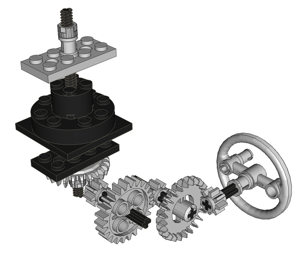
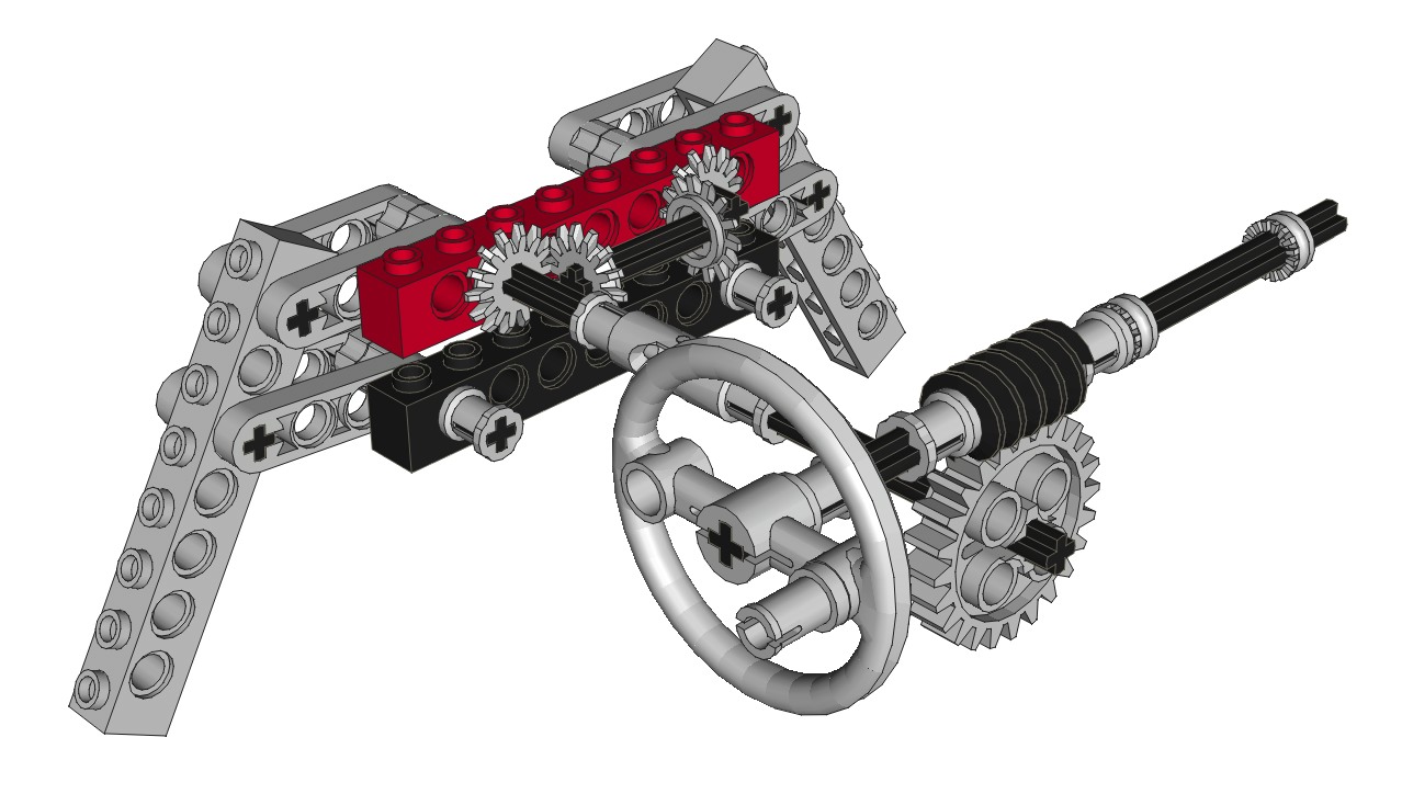
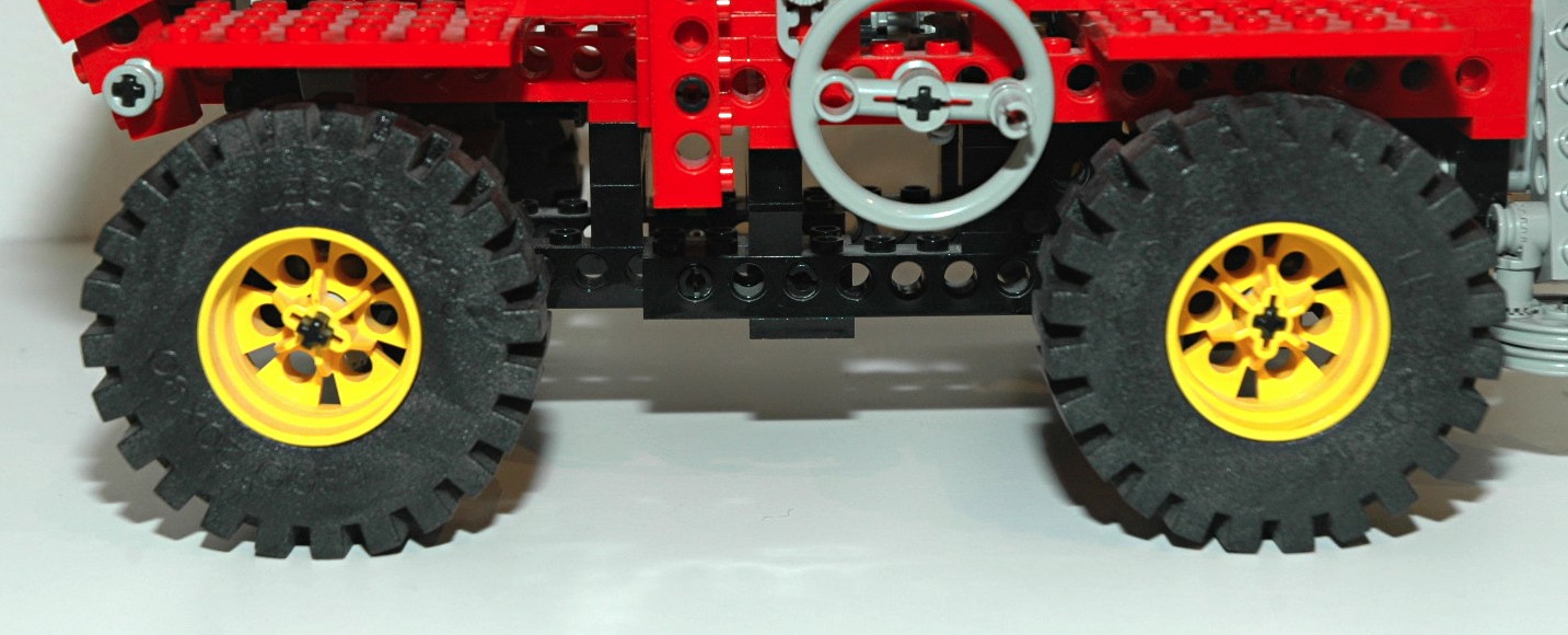
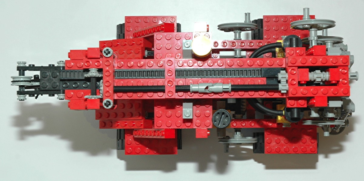
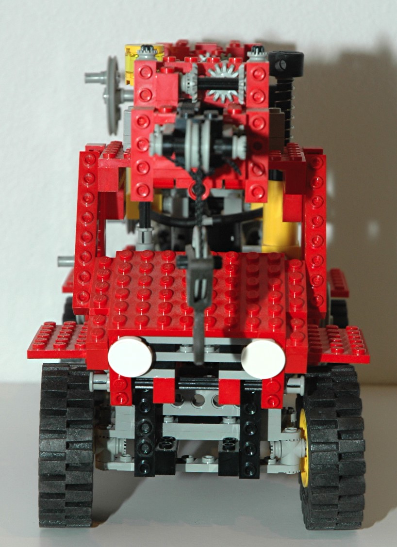
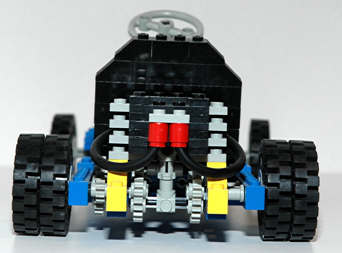
Steering
The front wheels can be steered using an overhead "hand of god" control. The overhead control drives
an axle connected to
a pair of 14 tooth bevel gears through a universal joint.
The second axle drives a rack via an 8
tooth pinion
gear. The steering mechanism itself uses the steering arms
and toothed links as shown in the computer image.
The steering knob is designed to look like a flashing light.
|

Ldraw file courtesy of Benjamin Wendl.
Click for an animation of the
steering in motion. |
|
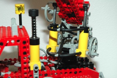
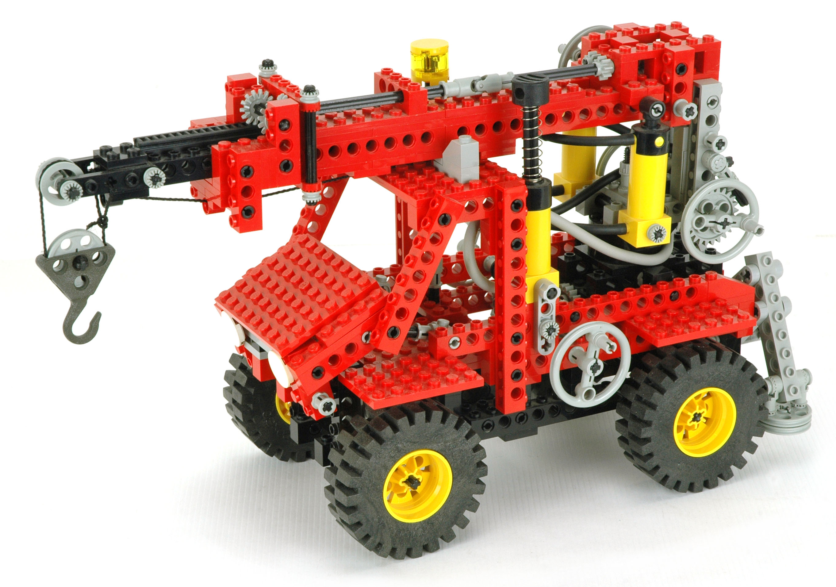
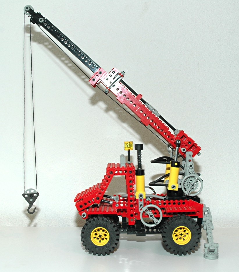
Luffing Boom
The boom can be pivoted from a position parallel to the ground up to an
angle of about 45 degrees. A pair of pneumatic actuators drive
this motion. They operate in parallel and extend to luff the
boom. The stroke of the actuators limits the extend to which the
boom can pivot. The actuators are quite powerful and have no
trouble luffing the boom, even when extended.
|
Click for an animation of the
boom
luffing.
|
|
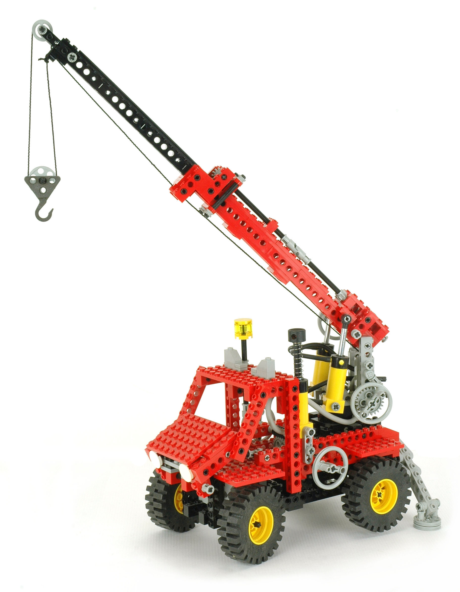
Telescoping Boom
The boom can telescope to approximately 160% of its original length. A
smaller inner boom is constructed of beams topped by the new 1x20
rack. A crank on the right side drives a an axle parallel
to the boom via a worm gear and an 8 tooth pinion. Another 8
tooth pinion then drives a long axle. This axle runs the entire
length of the boom, spliced with a u-joint. At the upper end of
the boom, the
rotation is turned 90 degrees through a set of 14 tooth bevel
gears. The
cross axle contains a final 14 tooth bevel which translates the entire
inner
boom axially as it mates with the rack.
There are stops at either end of the inner boom to prevent it from
extending or retracting too far. The cantilever moment of the
inner boom is carried by a force couple. The end of the inner
boom is prevented from moving down by contact with the main boom, and
is prevented from moving up by contact with the gear and with a
vertical clamping assembly.
As can be seen in the animation, the sheave is effectively raised by
the telescoping of the boom. Since the length of the boom has
increased, less cable is available in the vertical direction.
|


Ldraw file courtesy of Benjamin Wendl.
Click for an animation of the
boom
telescopic motion.
|
|
Hoist
A hoist is available which uses LEGO® string to
lift a sheave. Pulley wheels on either side are used as cranks
and directly
rotate an axle to which the string is affixed. This axle acts as
a
winding drum and raises and lowers the sheave.
A 24 tooth gear on the left side acts as a ratchet which mates with a
pawl. This supports the tension in the cable.
Even though the metal hook is fairly heavy, sometimes when the cable is
being payed out the weight is not enough to unspool it resulting in a
rat's nest of tangled cable.
|
Click for an animation of the hoist
in
motion.
|
|
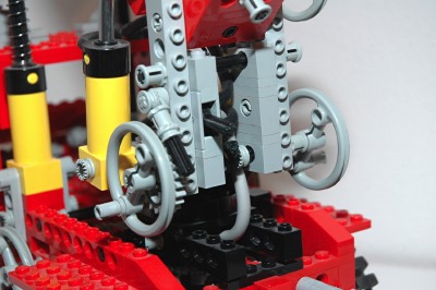
Slewing
The rotation of the boom is accomplished via a crank on the left
side. This crank passes torque through 3 sets of 8 and 24 tooth
gears, resulting in a final reduction of 27:1. The final gear
turns a threaded axle which passes through an old 4x4 turntable.
Axle nuts on the top and bottom of the threaded axle provide clamping
force which keeps the moment of the boom from tipping itself free of
the turntable.
Because the pneumatic hoses pass between the base and the boom, the
boom can only slew about 180 degrees before the hoses become twisted.
|
|
|
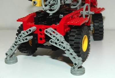
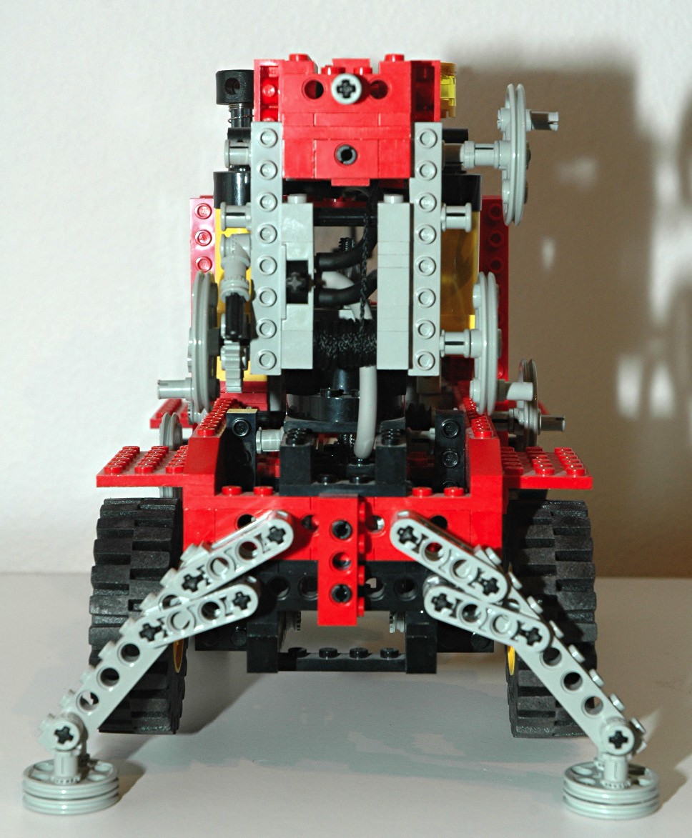
Outriggers
There are a pair of outriggers behind the rear wheels which are
constructed using the new 1x4 liftarms and standard beams. The
feet are made from small pulley wheels.
A crank on the right side drives a worm gear, which then drives a 24
tooth spur gear resulting in 24:1 reduction. The second axle
drives a pair of 14 tooth bevel gears. One bevel gear turns an
outrigger, while a parallel gear drives the other outrigger in the
opposite direction at the same time. When constructing the
outriggers, care must be taken to keep these two gears in phase so the
outriggers will be even.
Due to a careful selection of geometry, the outriggers are
self-locking. When fully deployed, weight on the foot tends to
rotate the two sets of liftarms together, locking the assembly, rather
than trying to backdrive them. It is this geometry, rather than
the worm gear, that prevents the outriggers from collapsing under
weight.
The outriggers provide a wide base for stability and are
slightly taller than the rear tires so that the tires are lifted off of
the
ground.
|

Ldraw file courtesy of Benjamin Wendl.
Click for an animation of the
outrigger
in motion.
|
|
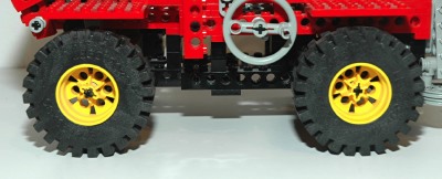
Wheels and Tires
This set uses four of the smaller size foam 20x30 tires and wheels. |
|


