Features
|
|
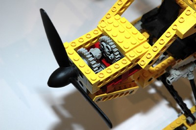
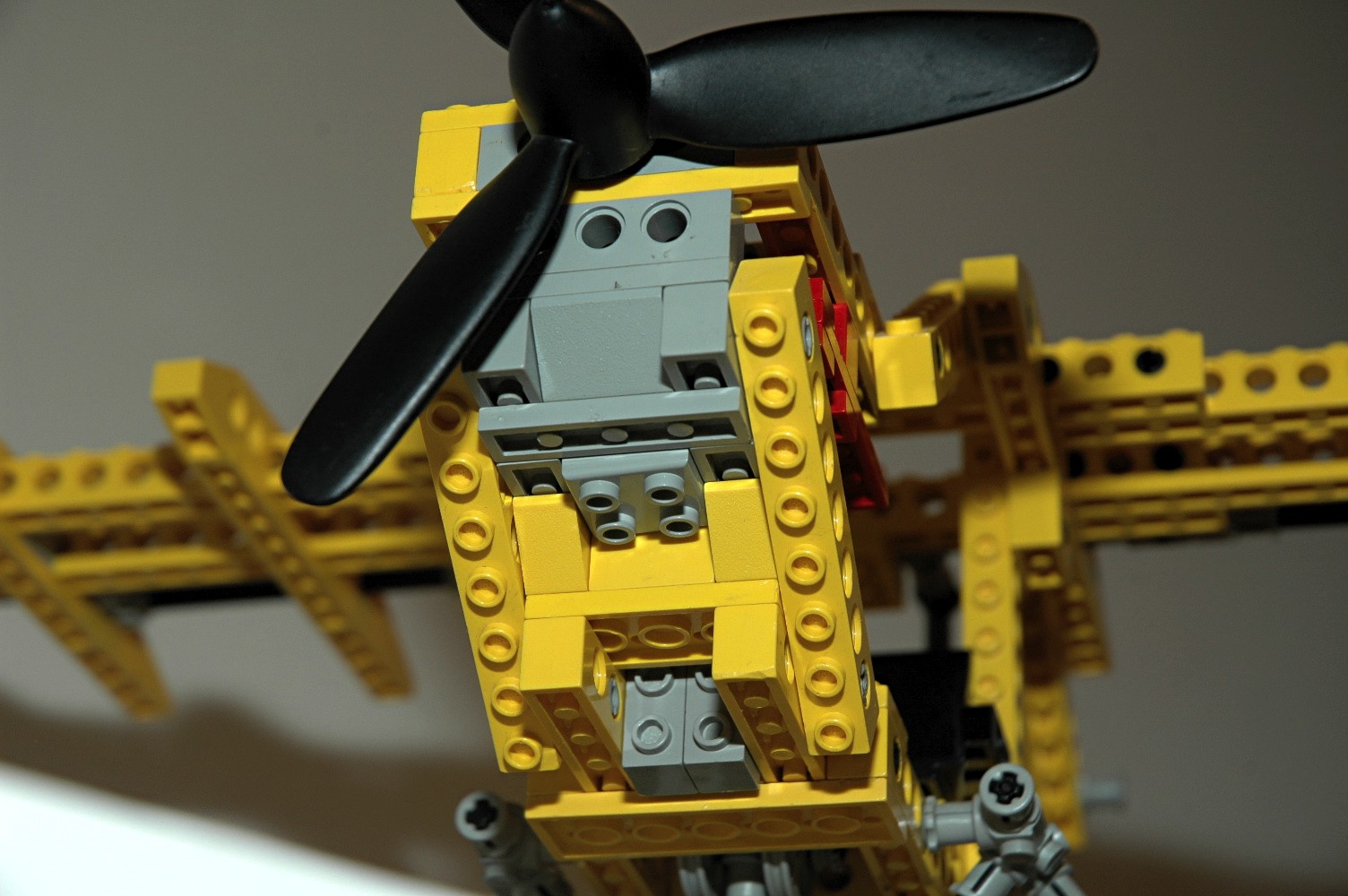
Engine
This single cylinder engine is not particularly realistic, but is the
only one which would adequately fit in the space available. The
cylinder actually faces down instead of up which would lead to
significant amounts of oil being burned, but no worse than many 1940's
era radial engines.
The unique 3 blade propeller passes through an integral 4L beam and
into a 24 tooth spur gear with an offset axle hole. The offset
axle holes of the 24 tooth gears are used to make a
crankshaft. Connectors placed end to end and clocked 90 degrees
form a rod which connects to a specialized 2x2 square piston. The
"cylinder" is actually square. |
Click for an animation of the
engine
in
motion.
|
|
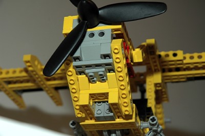
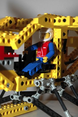
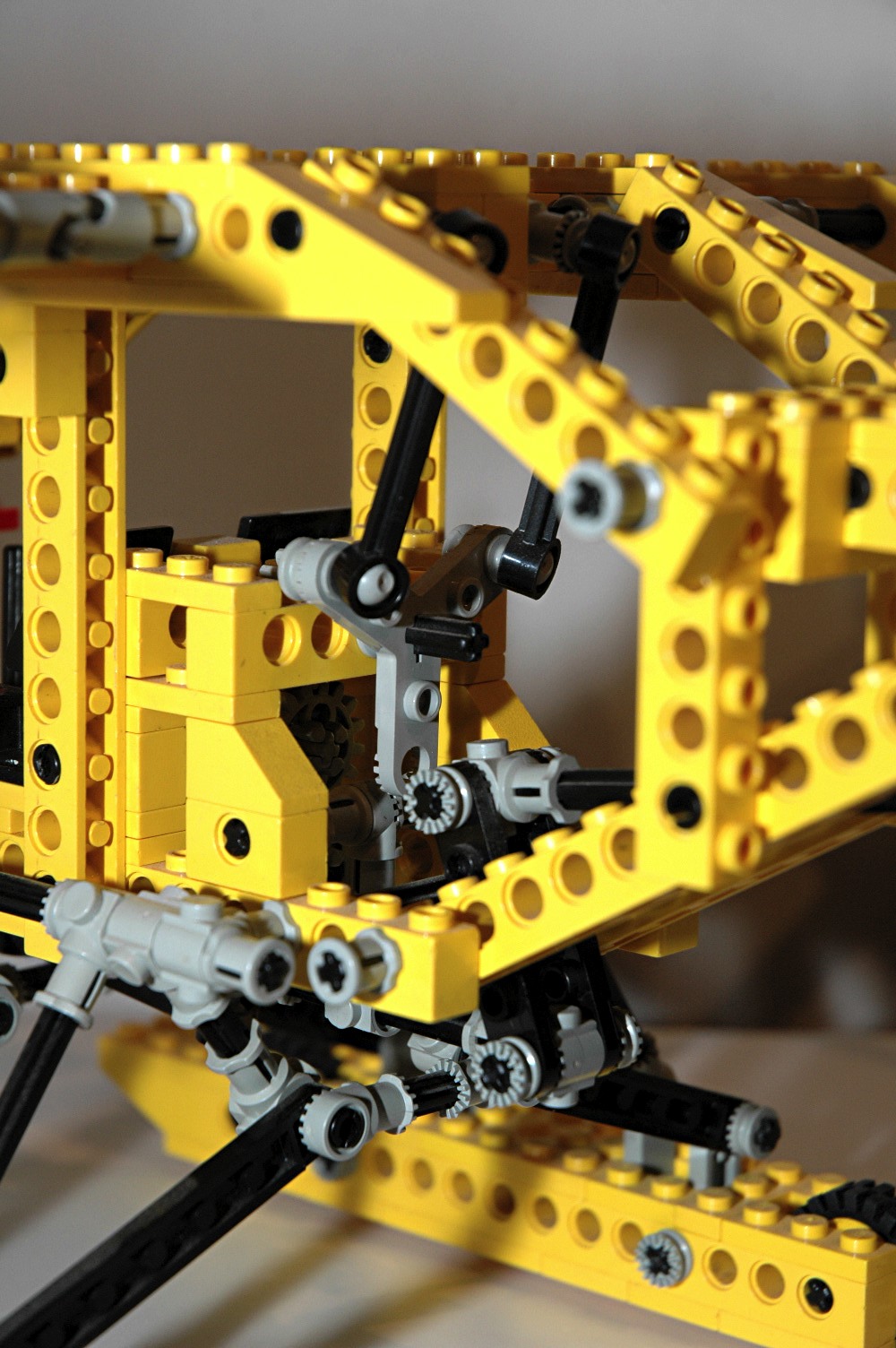
Pilot Controls
To control the rotation around the axes of 3-dimensional Euclidean
space, a real airplane uses a control column (or stick) and rudder
pedals. Movement of the stick fore and aft controls pitch, and
side to side controls roll. Aft stick is a nose up command, and
right stick is a clockwise roll. Rudder pedals control yaw.
This model accurately represents the function of the stick, including
moving in the right directions. There are no rudder pedals.
The only inaccuracy is that there should be a separate column for pilot
and copilot. Aircraft which use side sticks typically have them
at the outboard side, not in the center.
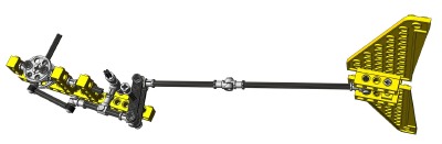
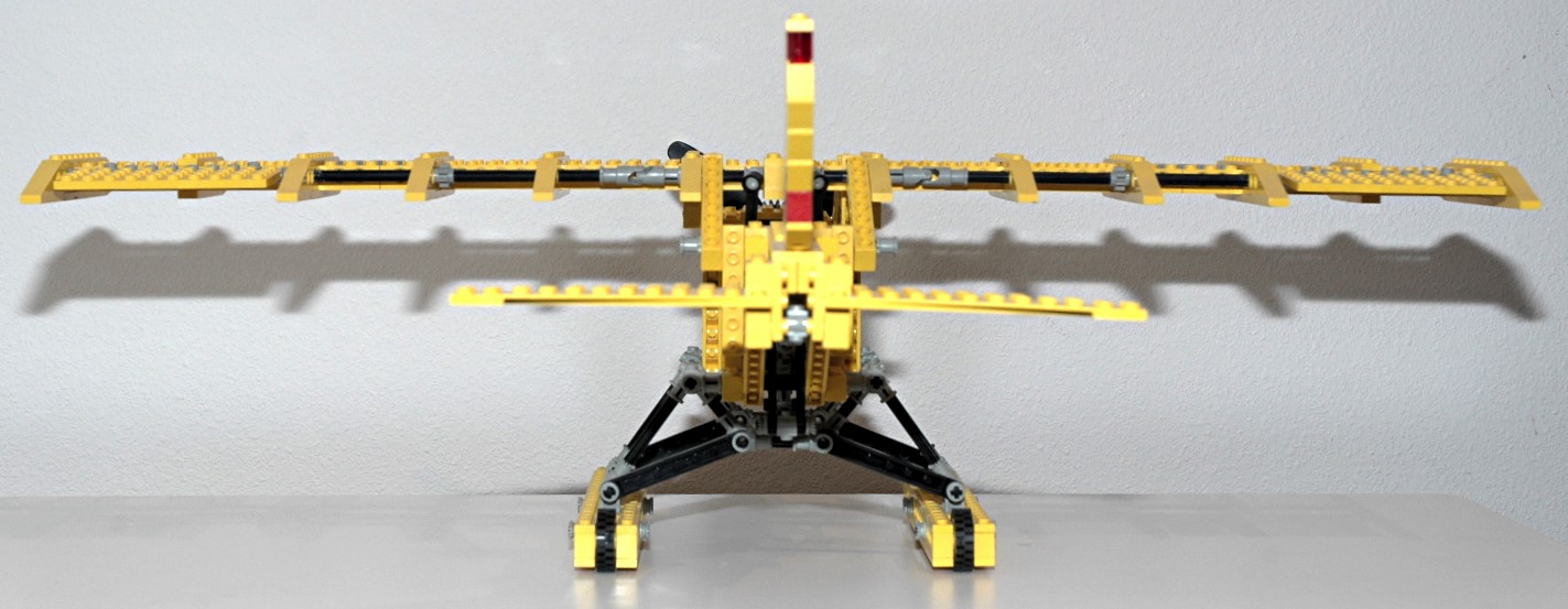
The second photo shows the interconnected mechanism which drives the
ailerons and elevators. More about this below.
|

|
|
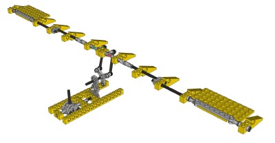
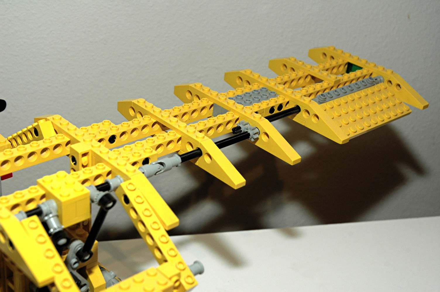
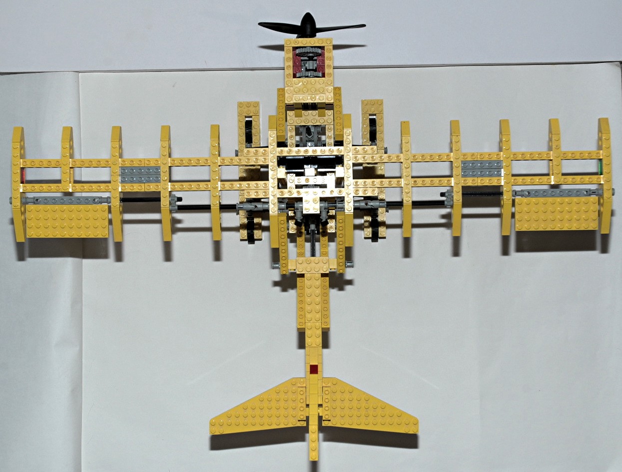
Ailerons
The primary control surfaces of aircraft which control roll are
ailerons. These panels on the trailing edge of wings move in
opposite directions (one moves up while the other moves down).
Large aircraft may have both inboard and outboard ailerons, and even
more roll control may be obtained through the use of flight spoilers.
In this model, left and right motion of the control stick rotates a
longitudinal axle. This axle drives a triplet of 16 tooth spur
gears. The final gear rotates a 3 blade rotor piece. A pair
of the new tie rods attach via ball joints to crank arms on the
wings. These crank arms turns axles which run outboard to the
ailerons. The direction of rotation is reversed via a pair of 8
tooth gears to make the aileron motion accurate with respect to the
control stick.
|

Click for an animation of the
ailerons
in
motion.
|
|
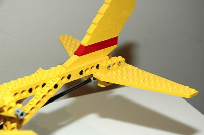
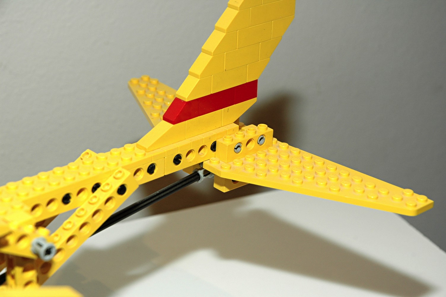
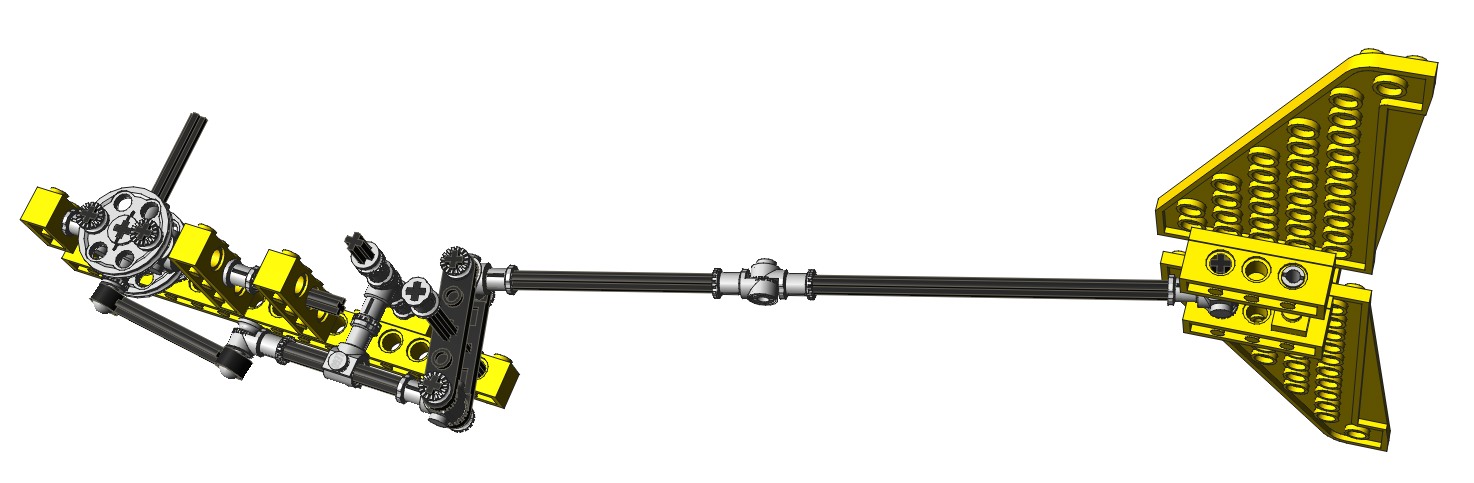
Elevator
The primary control surfaces of aircraft which control pitch are
elevators. These are typically panels on the trailing edge of the
horizontal stabilizer but, in this case, the entire horizontal
stabilizer pivots. This is sometimes called a "stabilator".
The two sides move in tandem, always in the same direction with respect
to each other.
In this model, forward and aft motion of the control stick pushes
and pulls one of the new tie rods via ball joints. The tie rod
pushes or pulls an axle which rotates a crank. The crank reverses
the direction of motion and then pushes or pulls a long link which goes
all the way to the tail. The stabilizer pivots around a pair of
pins. |
Click for an animation of the
elevators
in
motion.
|
|
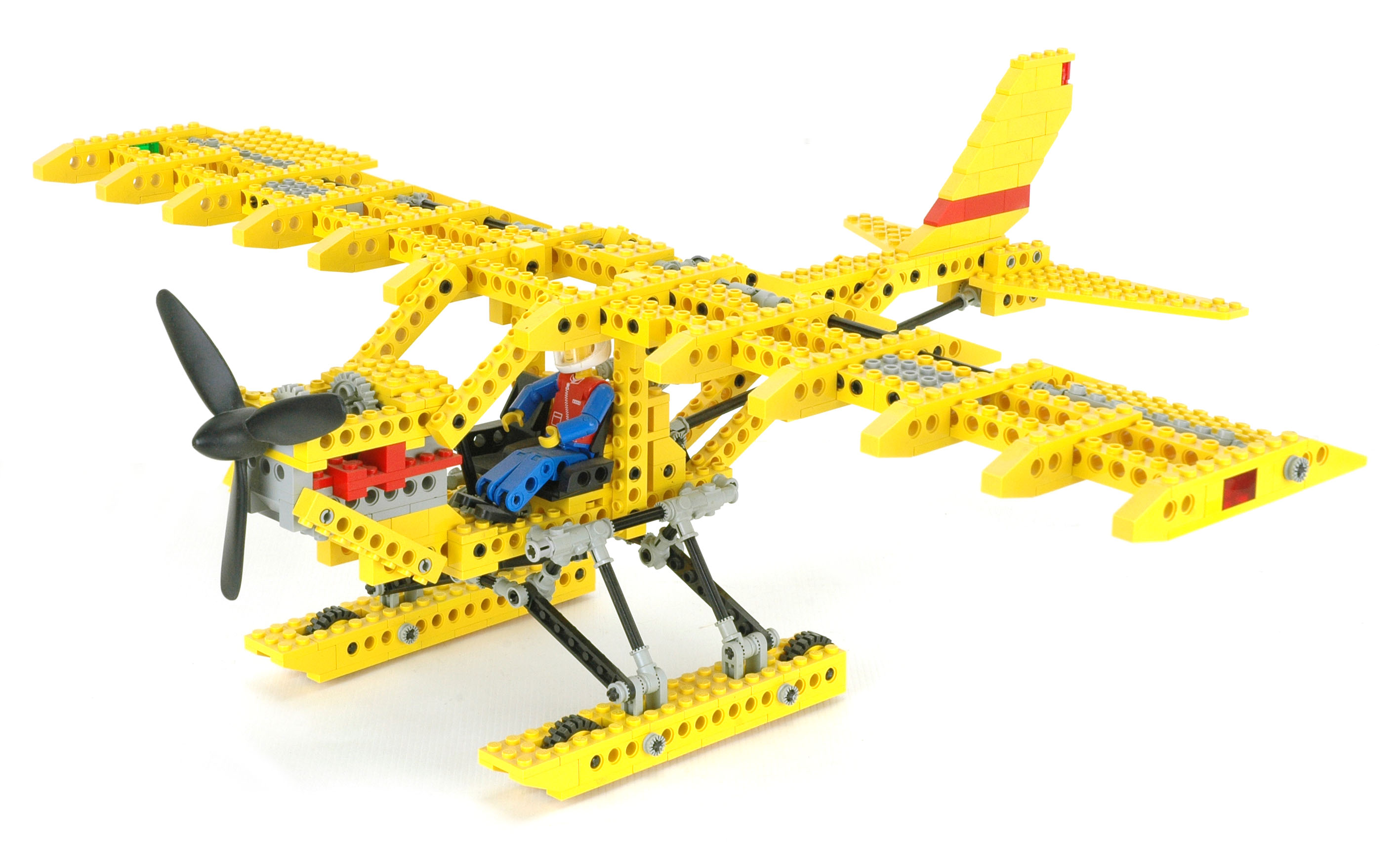
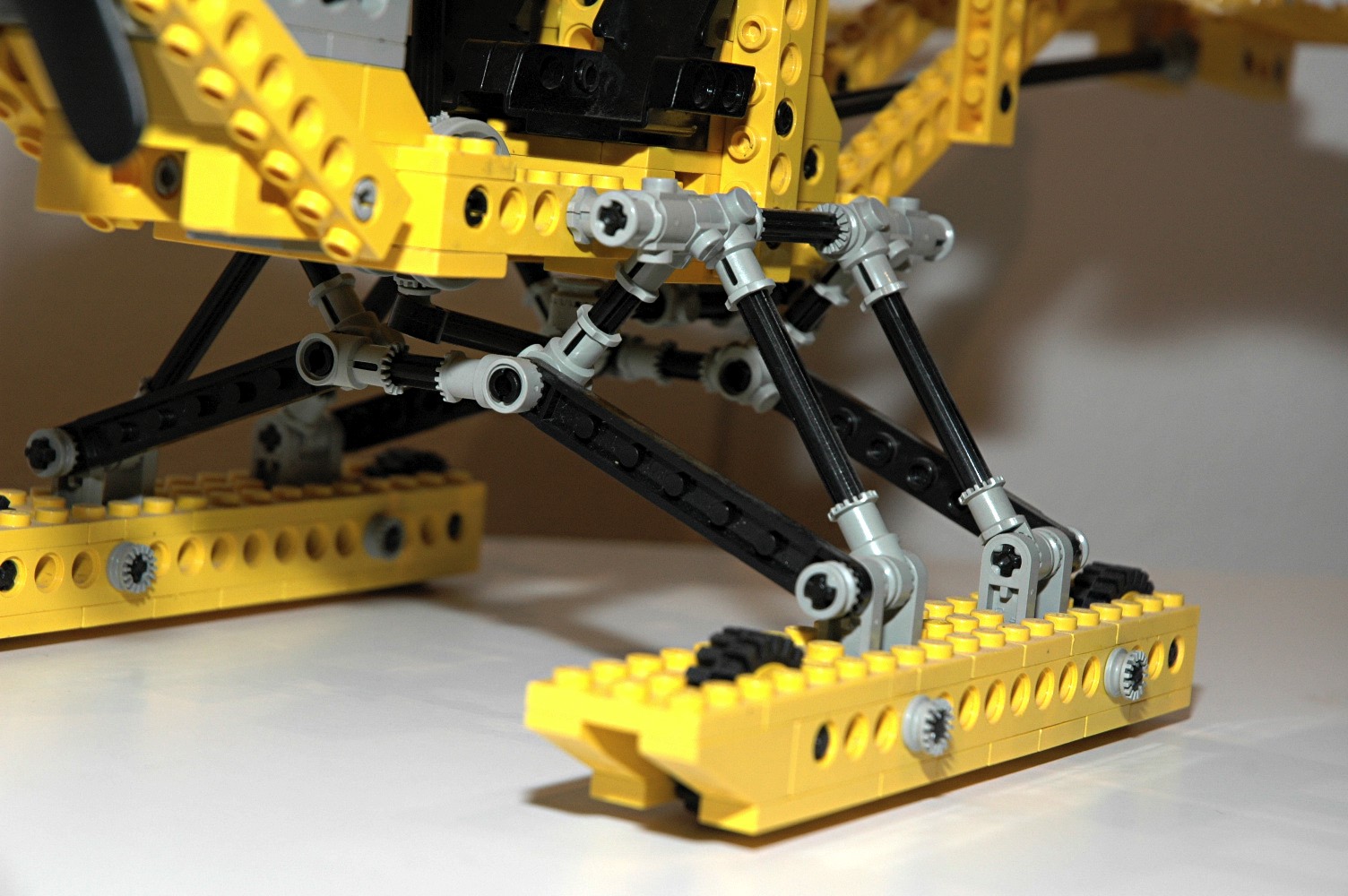
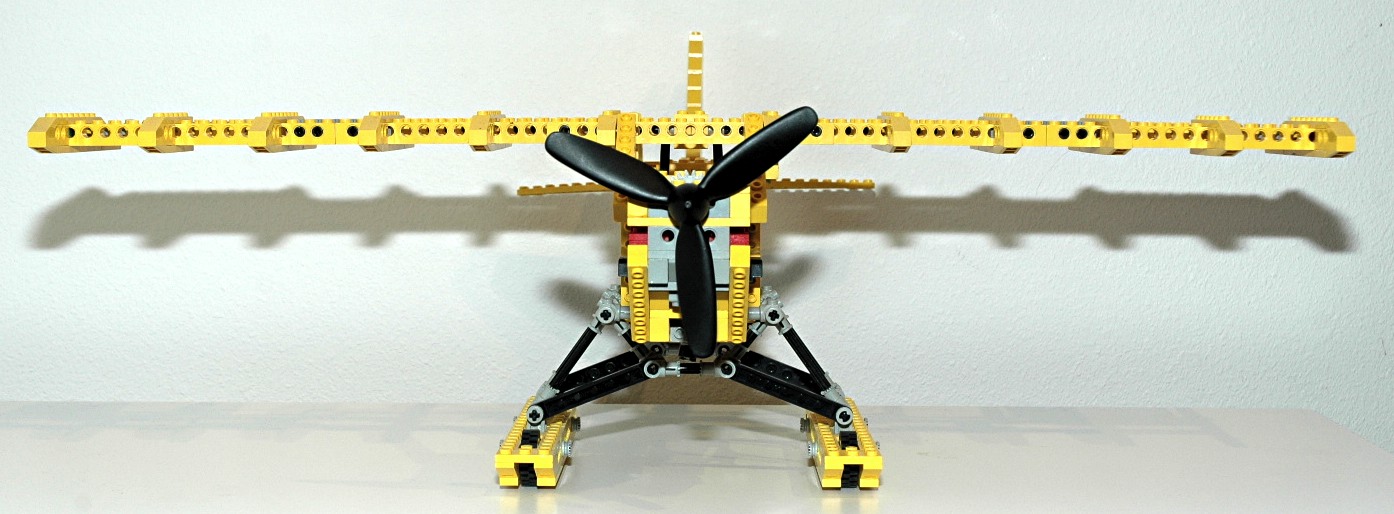
Skids
This aircraft has both floats and landing gear so it can be operated
from either land or water. The floats are supported by an
elaborate truss system constructed from toothed connectors as seen in
the photo. The 4 small tires are hidden within the floats.
|

|


