Features
|
|
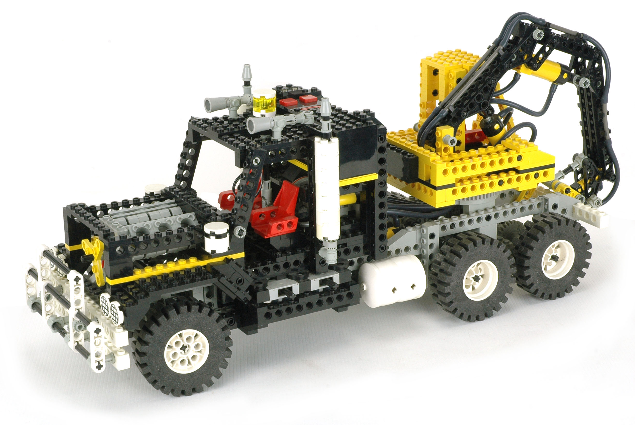
Pneumatics
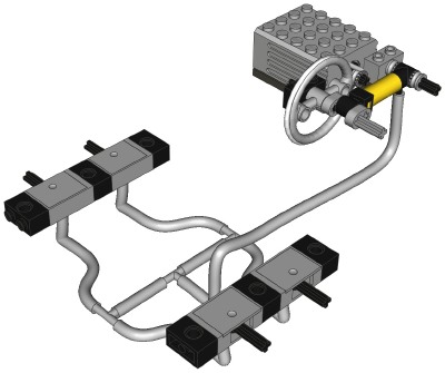
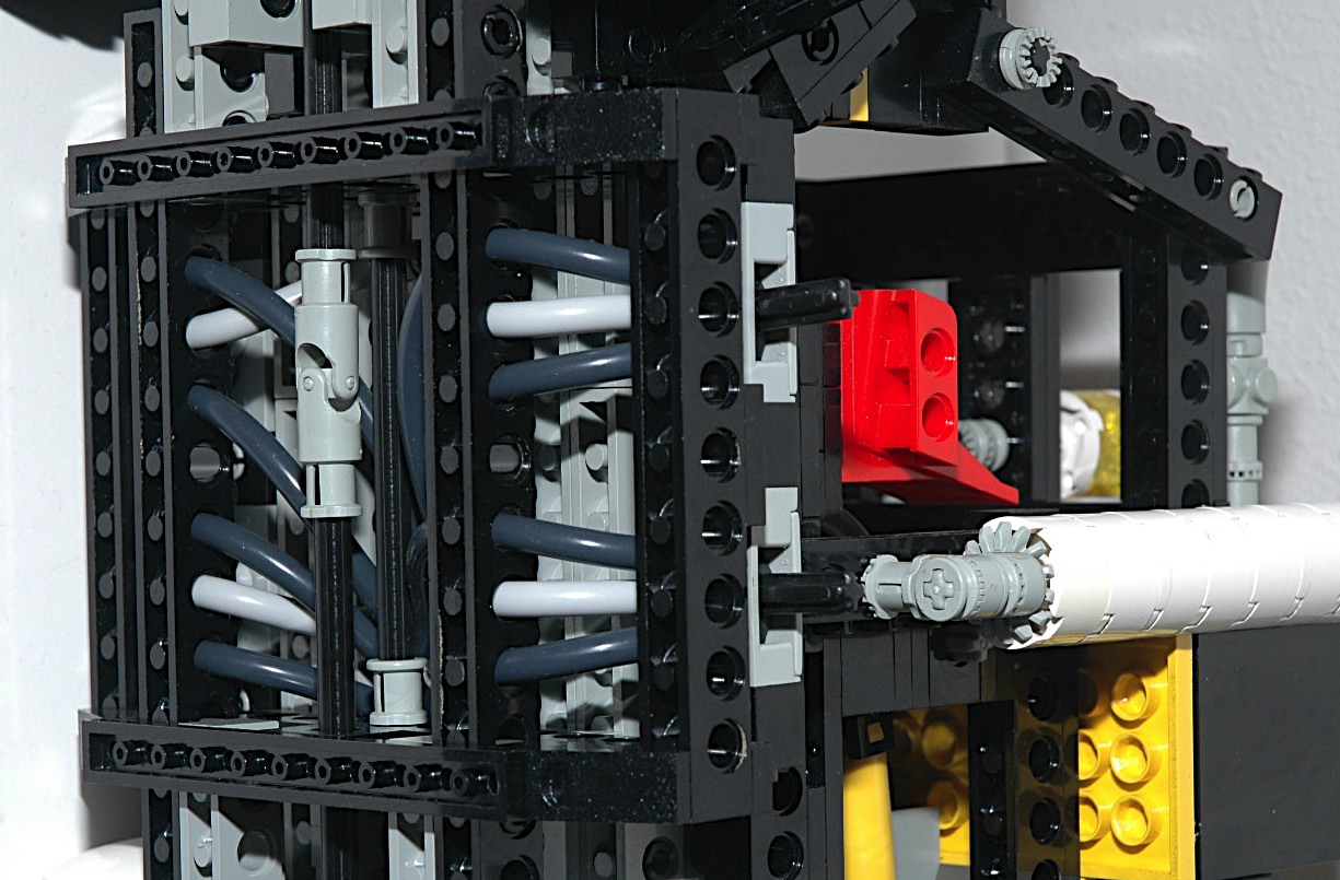
The pneumatics on this model are as complex as you will find on any LEGO®
model, and in fact this is the only set with a motorized
compressor. With a compressor, 4 switch valves, 4 large
actuators, one small actuator, and four rigid tubes, there are a total
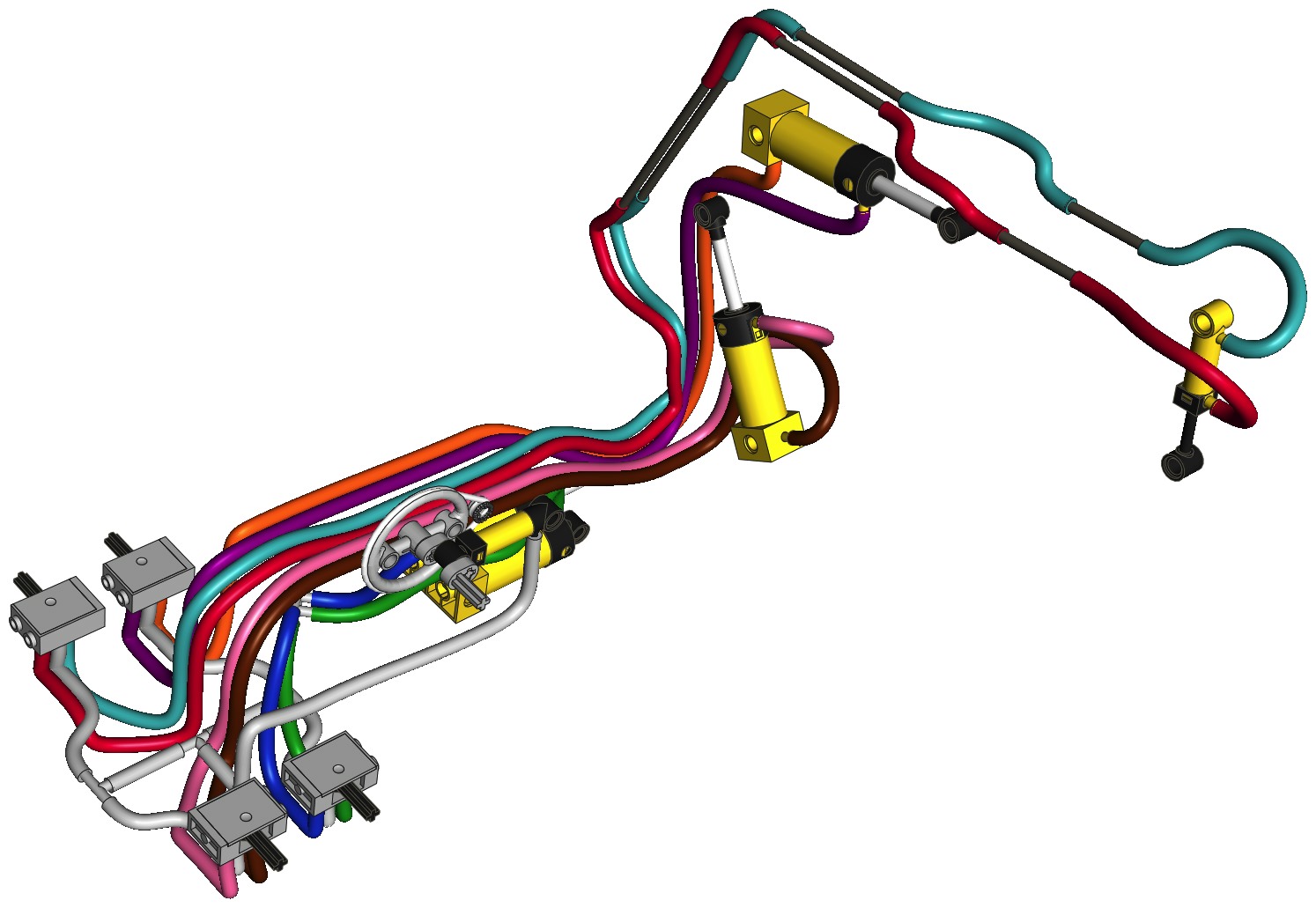
of 23 flexible pneumatic hoses to route through this behemoth. As
you can see in the pictures, there are two switches mounted
horizontally on either side with three hoses each passing through
holes in the Technic beams. Many of these hoses then pass aft
through another beam and up through the center of the turntable for the
loader. The color coded computer images can be used to decipher
the routing of the hoses in this system, which can then be used to
derive the logic of this mechanical computer.
A single compressor is integrated into the body. The pressure is
split and fed to the inlets of
four selector
valves (switches) with two outputs each. Selection of the
switches in
either direction allows pressure to flow to either chamber of the
actuators.
There are five pneumatic actuators which have ports at the
head and rod ends
to accept input from the switches. Head end pressure extends the
piston, while rod end pressure retracts it. The
actuators are designed to work in compression during their power
stroke. A real hydraulic actuator has significantly less output
force in tension than in compression due to the fact that the annular
area of the rod end of the cylinder is less than the full bore area of
the head end.
Because there is continuous supply of pressure, this model operates
very smoothly and multiple functions can even be run
concurrently. One (or two) of the pneumatic air tanks which came
out years later make great replacements
for
the fuel tanks and really bump the functionality up to the next
level with a virtually limitless source of pneumatic power. I'm
sure no one will have any trouble finding a place to route even more
pneumatic hoses!
Incidentally, if you are wondering how long it took me to model all of
those pneumatic hoses on the computer, the amount of time is too long
to comprehend.
|
|
|
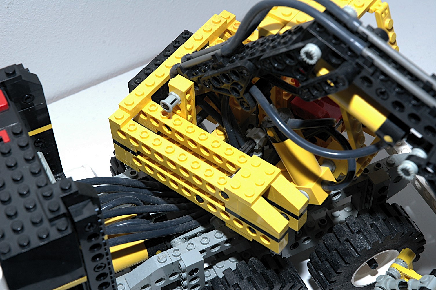
Motorized
Compressor
Feast your eyes on the only Technic pneumatic compressor. Why
they never used this again is one of the great mysteries (and
tragedies) of our time.
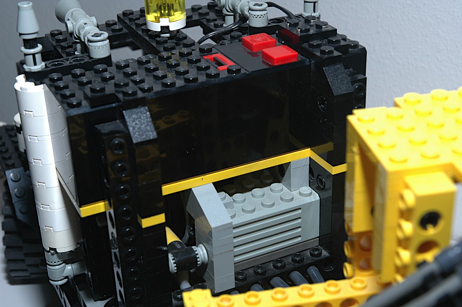
For the first time, a 9V battery box was actually integrated into the
body of a model instead of being remote. This serves to make this
model pretty heavy. There's a 9V motor mounted under the battery
box which drives a large pulley through a belt. On the axis of
the pulley is a crankshaft part with an offset of 1/2 stud.
Reciprocation on this crank gives the compressor cylinder a stroke of 1
stud. Due to the small gear ratio, it operates very fast.
The compressor cylinder itself looks like a small actuator but has a
port only at the head end. When driven to retract, it forces air
out through the port. When extending, it draws in air from the
atmosphere. There is an integral relief valve which prevents the
pressure from building above a safe level, although the torque required
to drive the compressor to relief pressure slows the motor considerably.
The computer image shows the compressor's input to the four
switched via three T-fittings.
|

Click for an animation
of the
compressor in motion.
|
|
Pneumatic Slew
By this time, there had been quite a few cranes which featured a
slewing turntable, but this is the first time it was controlled
pneumatically (and it only happened one more time many years
later). Even though the model had a motor, the turntable could
not be driven through a gear system because LEGO® had no
synchronized transmission to switch between compression and gear
functions. (Note the foreshadowing.)
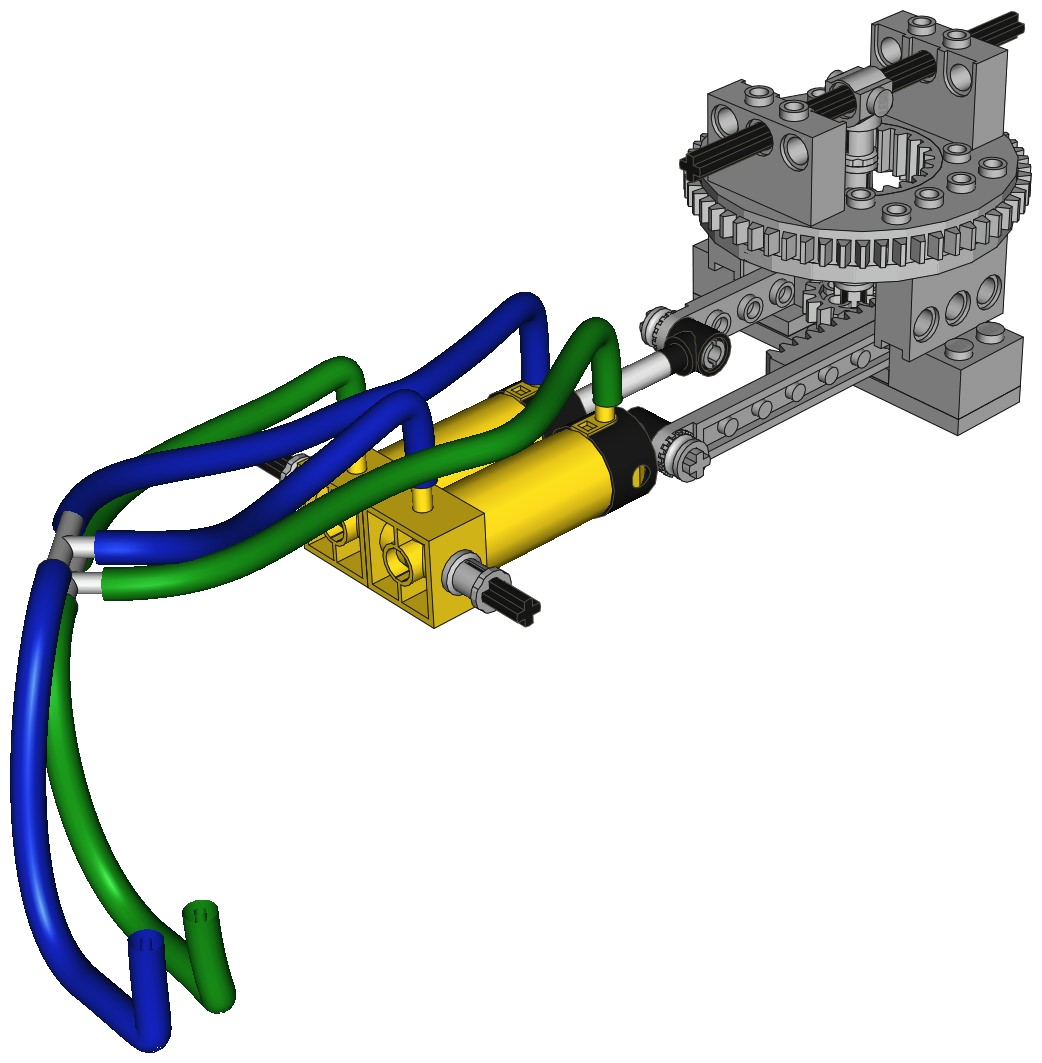
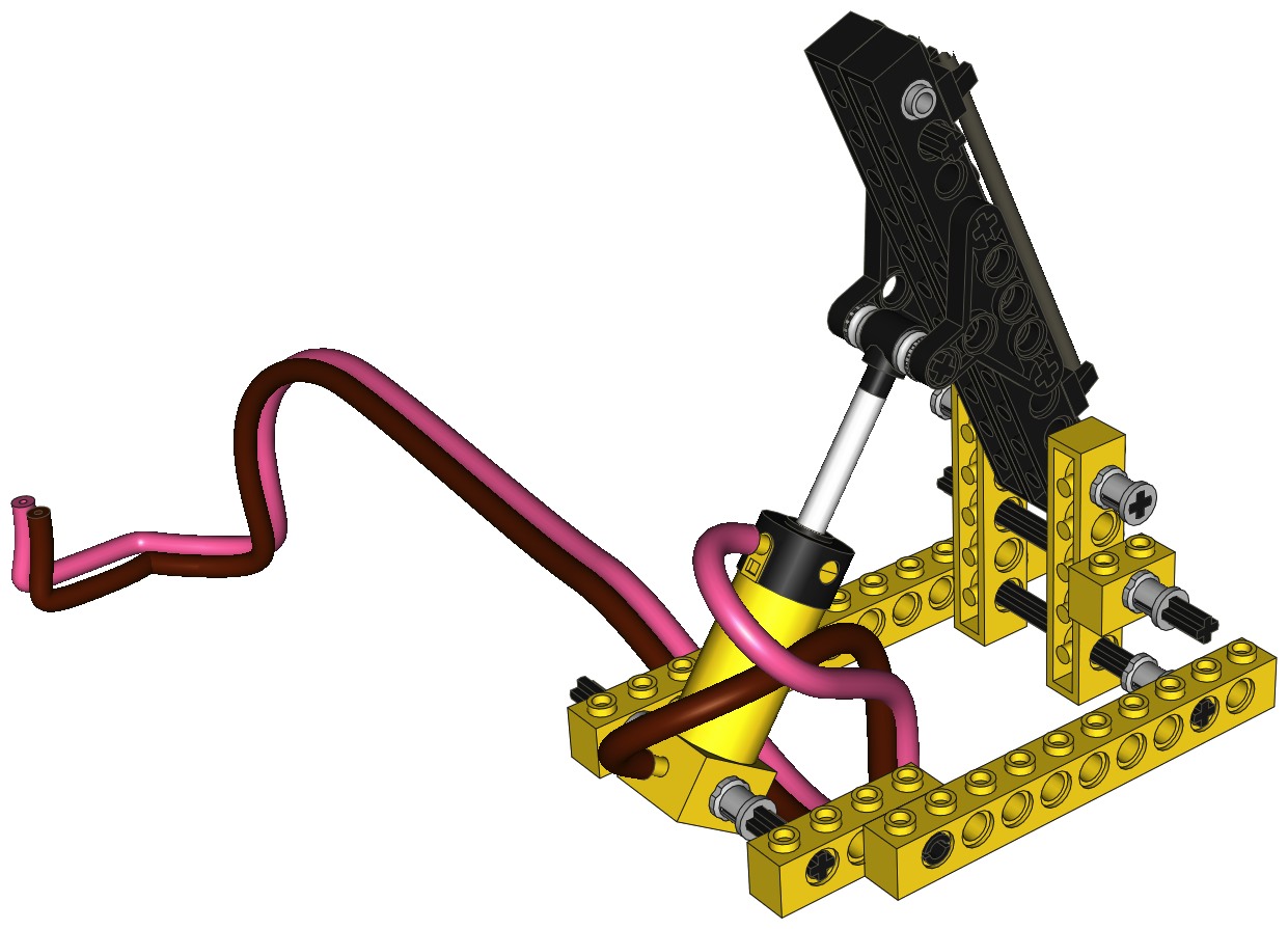
The color coded computer image shows the way the dual pneumatic
cylinders are cross connected. The head end of one actuator is
connected to the retract port of the other. This way, pressure
causes one to extend and one to retract simultaneously. A pair of
rack gears are connected to the actuators and are used to turn a 16
tooth spur gear. Since the bottom half of the turntable needs to
remain fixed, a unique driving method was required. A vertical
axle which connects to the 16 tooth gear drives a horizontal axle which
passes through the holes in the upper turntable. It is important
to get the two actuators even and centered when rigging the system to
make sure that it can rotate 90 degrees in either direction.
Because all of the other pneumatic hoses have to pass through the
center of the turntable along with the driving axle, the crane can only
turn so far before the hoses snag. Extra length is required when
at the centered position.
A weighted 2x6 brick is located at the back of the crane to act as a
counterweight so that the turntable is reasonably balanced.
|

Click for an animation of
the loader
slewing. |
|
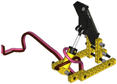
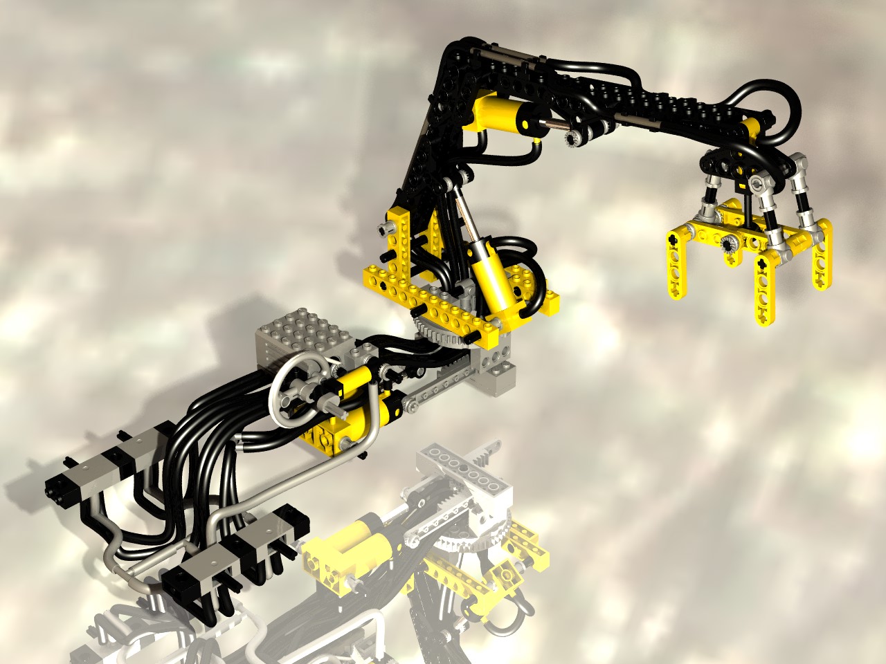
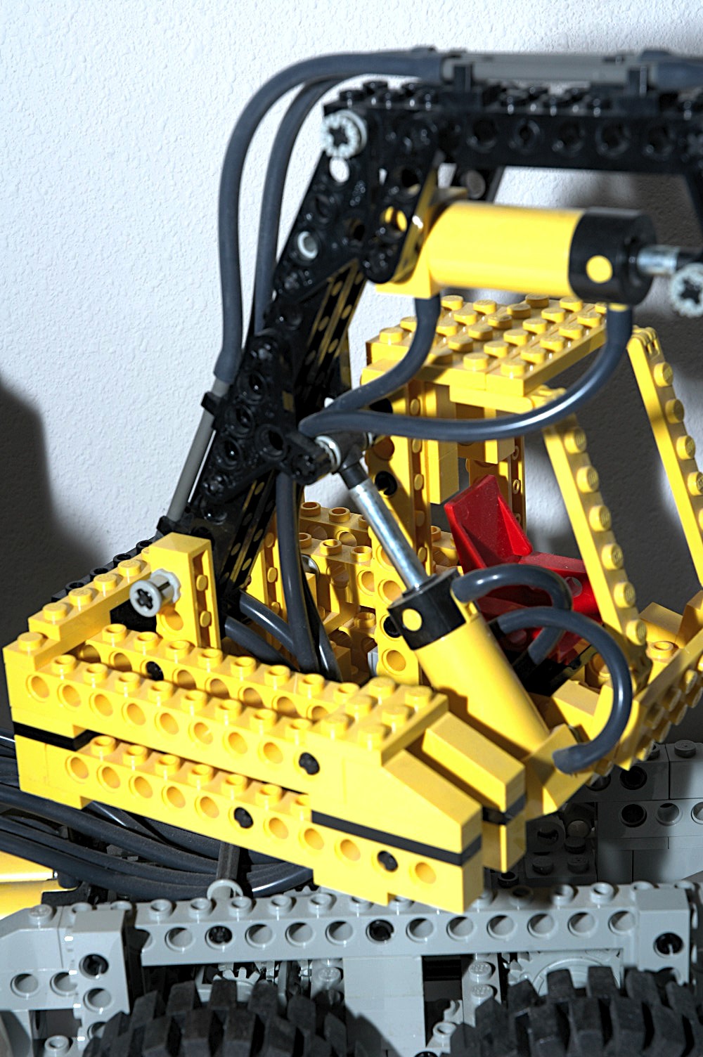
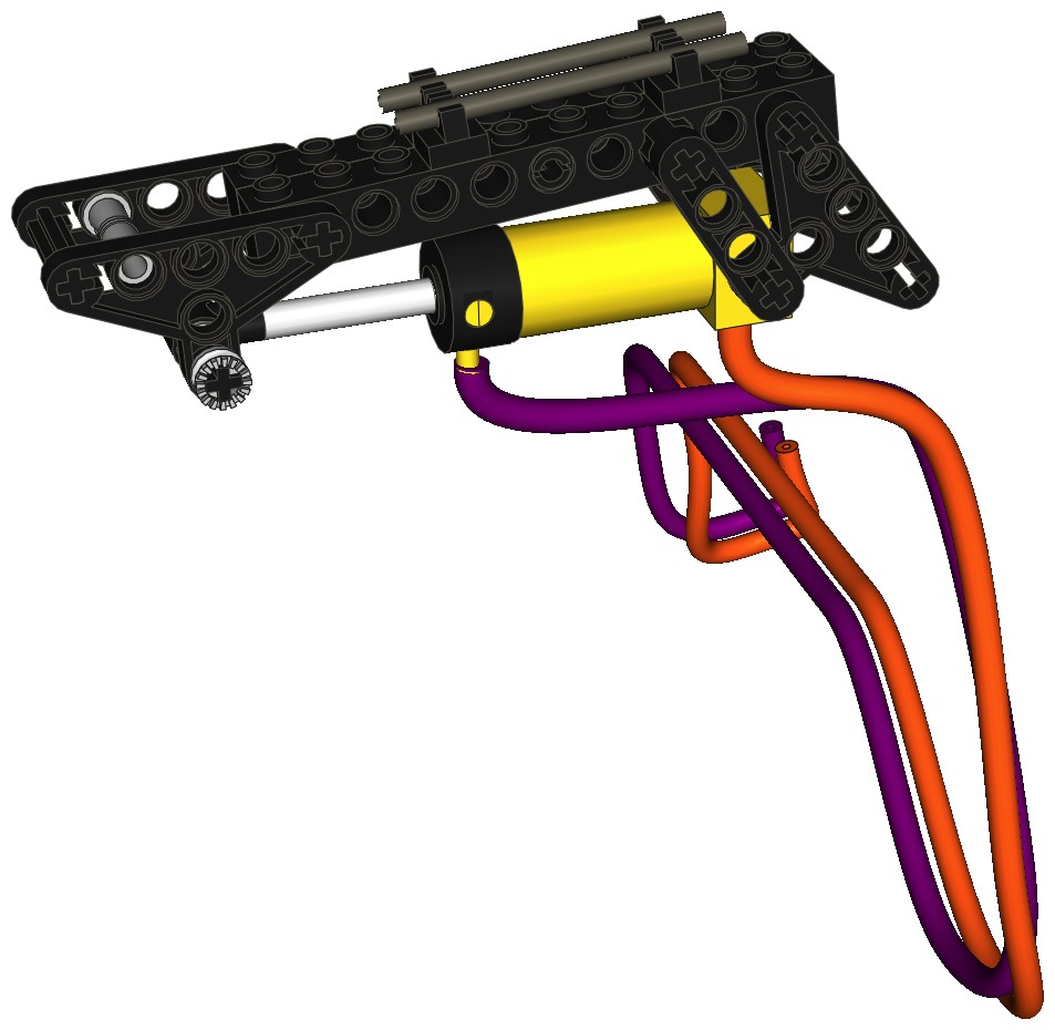
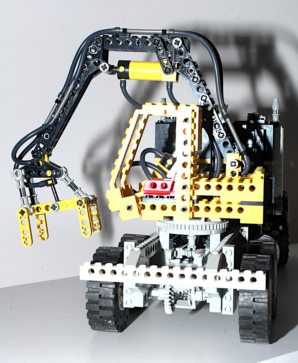
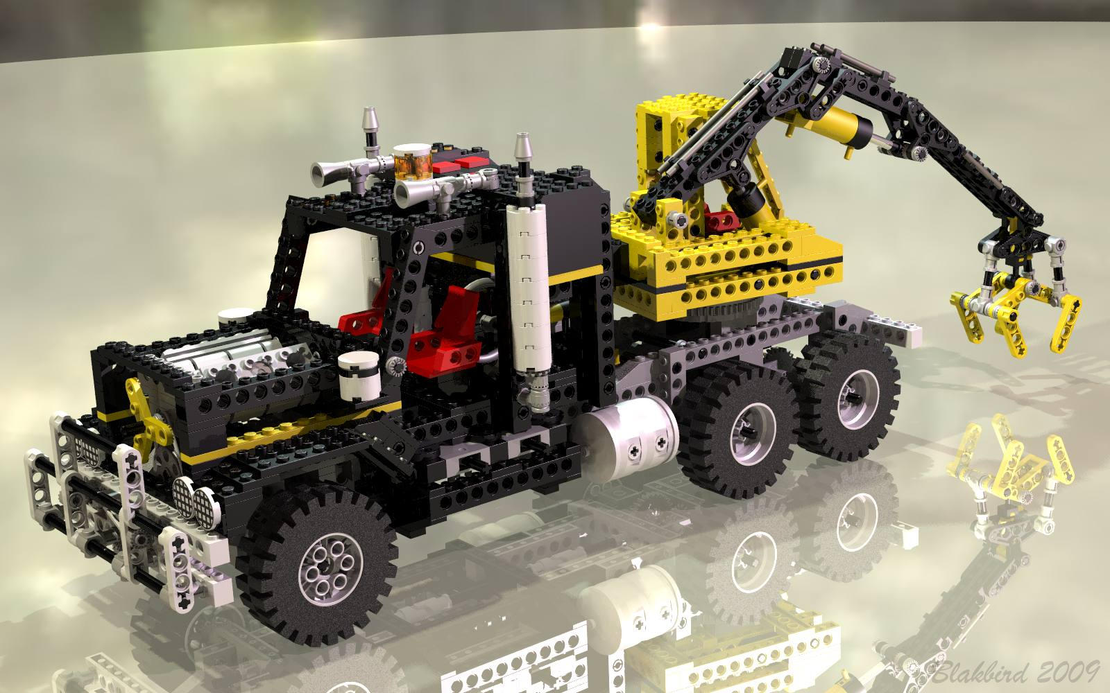
Pneumatic Boom
The main boom can be luffed via a single pneumatic cylinder working in
compression. The actuator attaches almost half way along the
length of the boom. This gives it excellent mechanical advantage
to lift the weight, but also means that the total boom rotation is
small; in this case about 45 degrees.
Technic "triangles" are used as lugs to attach to the rod end of the
actuator. The compressor has plenty of pneumatic pressure to lift
the boom, even at full extend.
|

Click for an animation of
the boom
in motion. |
|
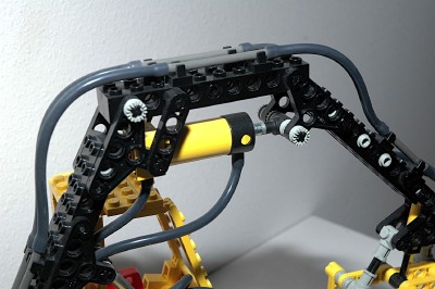
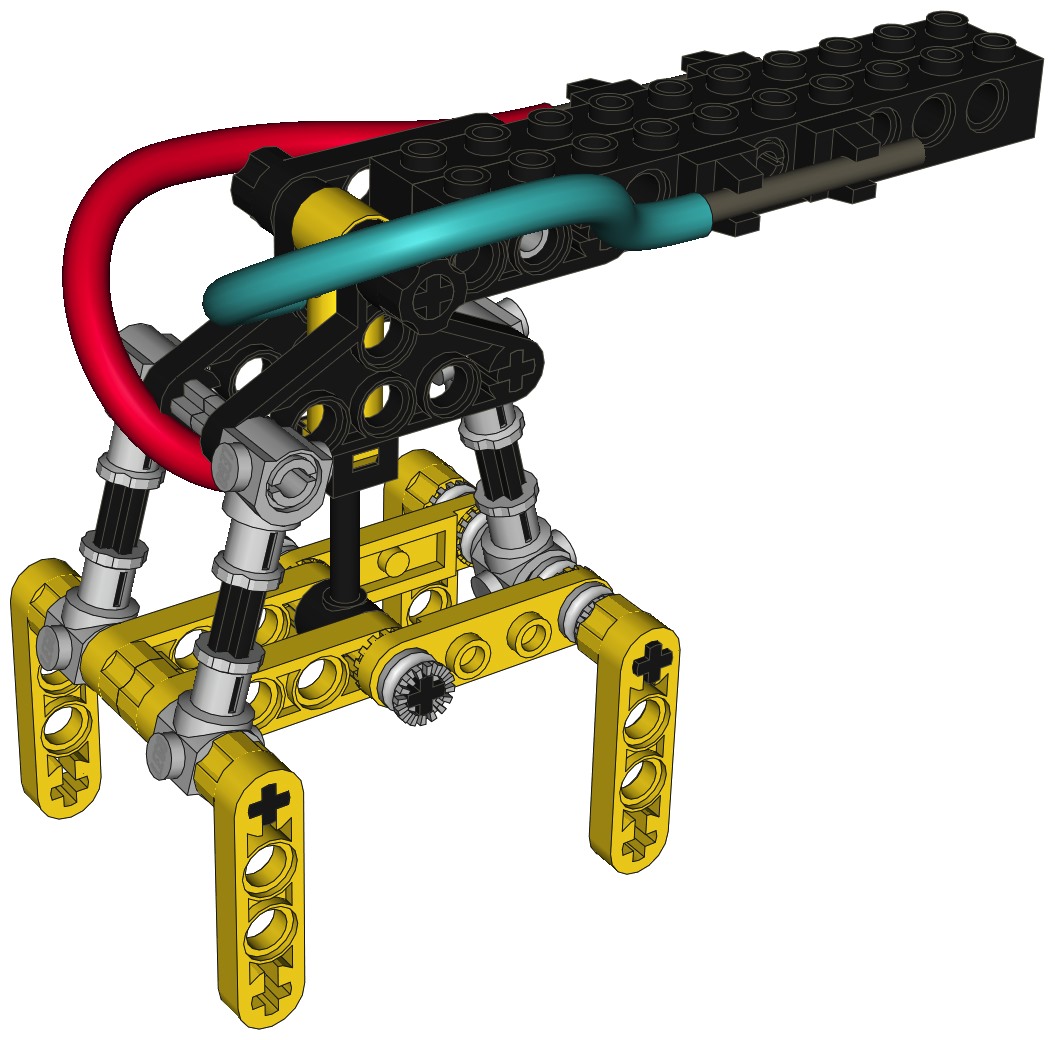
Pneumatic Jib
The jib has two sections, a fixed section and a movable section.
The angle of the first section with respect to the boom is about 135
degrees and is locked by triangles and lift arms.
The second section is movable and is lifted by a single pneumatic
actuator driving another pair of triangles. Compared with the
boom actuator, this one has fairly poor mechanical advantage, but less
is required due to the decreased moment arm of the lifted load.
The smaller arm allows a greater range of motion; in this case almost
90 degrees.
|

Click for an animation of the
jib in
motion. |
|
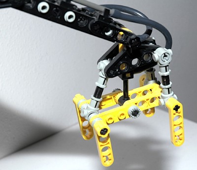
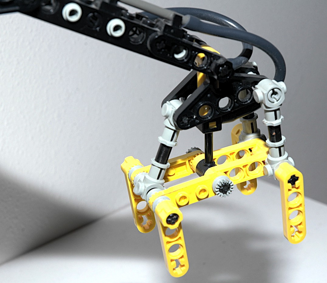
Pneumatic
Claw
A grasping claw on the end of the jib is driven by one of the new
miniature pneumatic actuators. Because of the very small area,
this actuator has a small output force and the grip of the claw is not
very strong, but it does the job. Unlike the other actuators,
this one has to work in both tension and compression, and in fact the
lower tension force is what is used to close the claw.
The actuator attaches to the middle hinge point of the claw which
allows it to drive both sides at once. The outer angle of the
claws is fixed at 90 degrees. The claws are supported by 3 arms
which are free to pivot at the ends. This allows the claw to
remain perpendicular to the ground no matter what the jib angle is.
A look at this computer image and those in the above sections will
demonstrate that the hose's path to this actuator is pretty
circuitous. Flex system rigid sleeves are used as pneumatic tubes
to span the sections between the pneumatic hoses. This allows
them to be clipped to hooks which makes certain that the hoses move
with the boom and jib and do not become tangled.
The claw can be lowered to grasp the rear bumper to help keep the crane
stable when the truck is in transit.
|

Click for an animation of
the claw
in motion. |
|
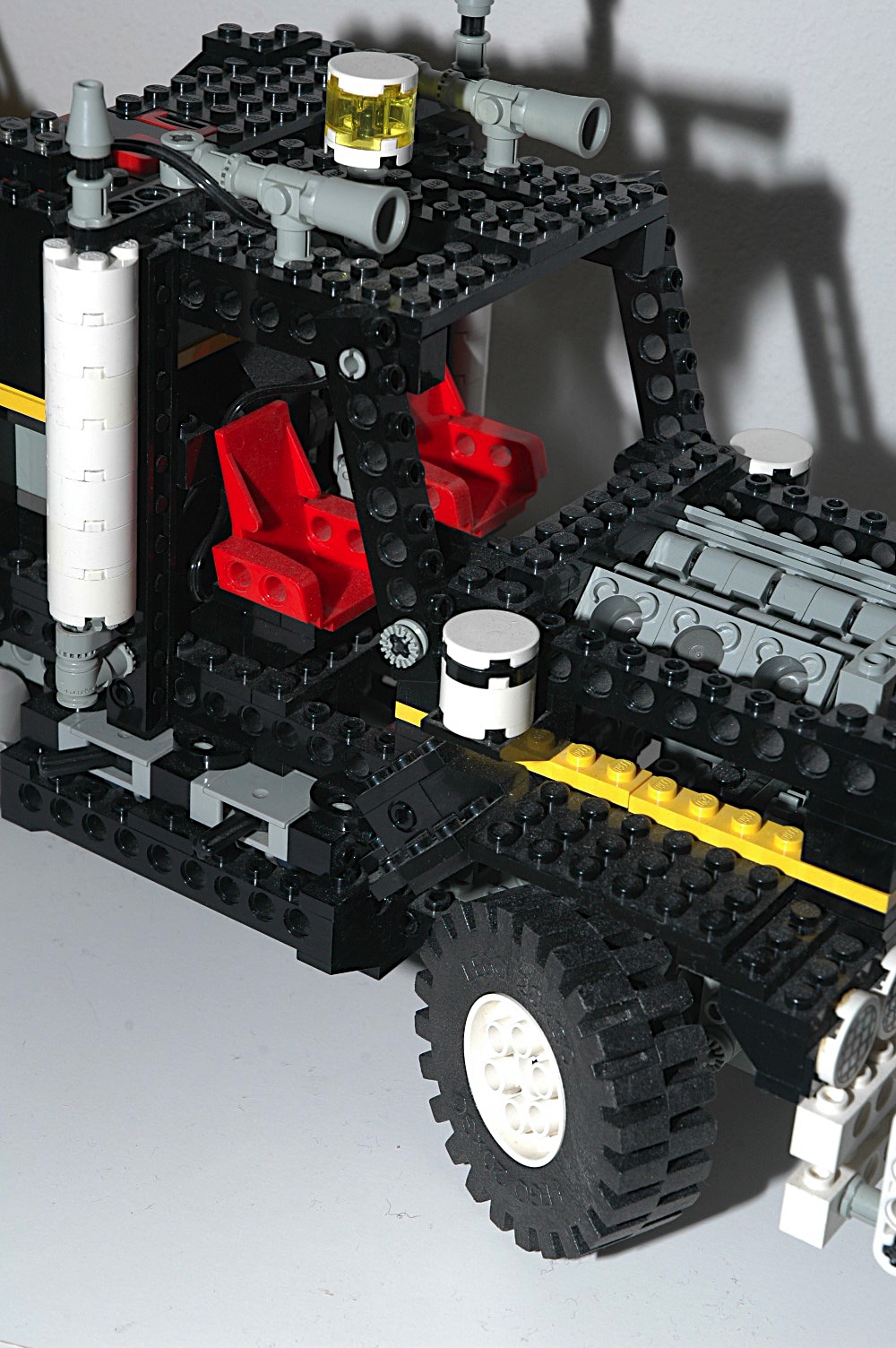
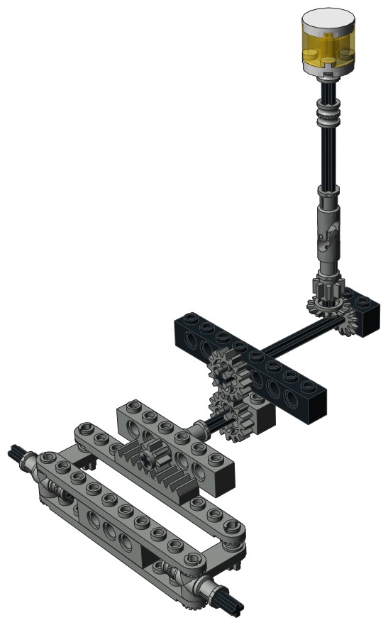
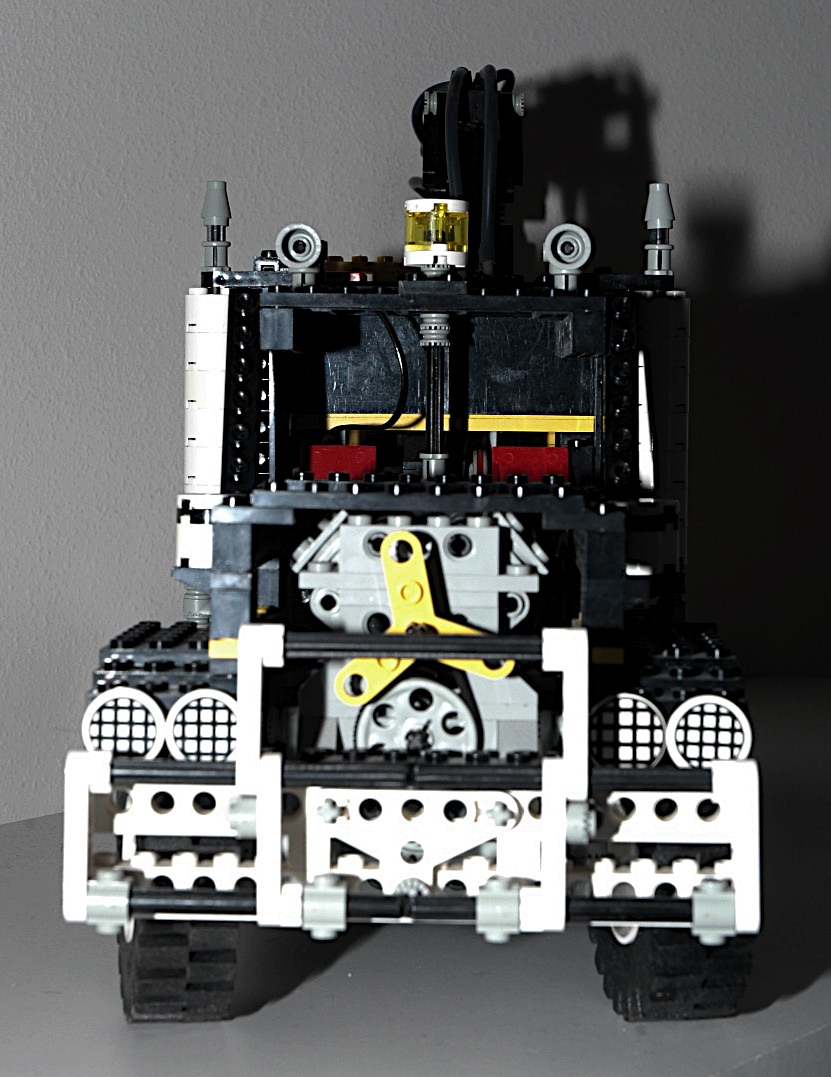
Steering
The front wheels can be steered using an overhead "Hand of God" control.
The overhead control drives an axle connected to a pair of 14 tooth
bevel gears. The second axle drives a pair of 16 tooth spur gears
and then the steering rack via an 8 tooth
pinion
gear. The steering mechanism itself uses steering arms and
toothed links as shown in the computer image. The steering arms
may seem small for a model of this size, especially since the weight of
the model is cantilevered out the wheels via only a single hole as a
support couple. But it seems to work fine.
|
Click for an animation of
the
steering in motion.
|
|
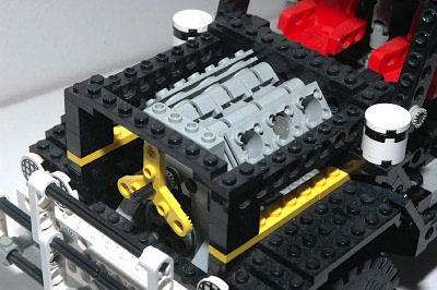
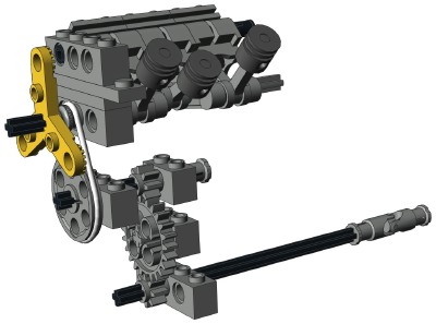
Engine
The rear wheels are used to drive a V-6 engine. Torque from the
differentials passes through a long drive shaft to a point under the
front of the engine. A combination of an 8, 24, and another 8
tooth gear pass the torque up without changing the gear ratio or
direction. A belt then actually drives the crankshaft of the
engine via a pair of pulleys which increase the rotation about 3
times. This makes the engine turn fast.
The front of the crankshaft uses a 3 blade rotor as a fan.
The engine is made from cylindrical engine elements. The two
cylinder banks have a standard V angle of 90 degrees. The
crankshaft is
offset 1/2 stud from center, giving the pistons a stroke of 1
stud. Each pair of pistons shares a common crank pin.
Because the crank pins are each offset 180 degrees, the forward and
back cylinders are synchronized. This can be seen clearly in the
animation.
A big diesel truck like this would indeed probably have a large
displacement 6 cylinder engine (although probably inline), so this
engine fits very well.
|
Click for an animation of the engine in
motion.
|
|
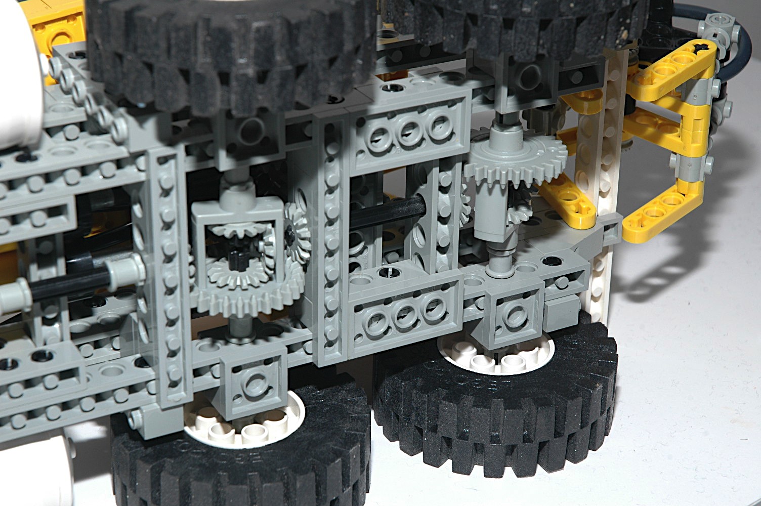
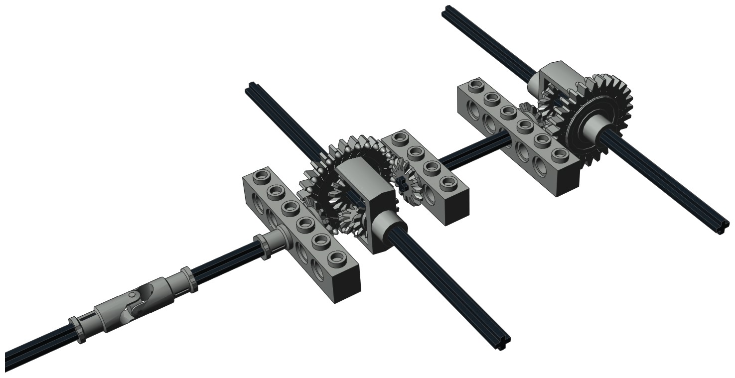
Differentials
The dual rear axles are both "live" and use a pair of differential
gears which incorporate a built in 28 tooth ring gear which can work
either as a
bevel or a spur, similar to the 24 tooth crown gear. The
differential ring gears are linked via an axle with 14 tooth bevel
gears at either end. While this allows them to rotate at the same
rate, it could make one differential rotate backwards. To solve
this, the ring gear of the second differential is located on the
opposite side.
The differentials are made
to house 3 of the 14 tooth bevel gears. One is on each axle,
and one planet gear in the middle allows the axles to turn at different
rates.
|
|
|
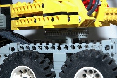
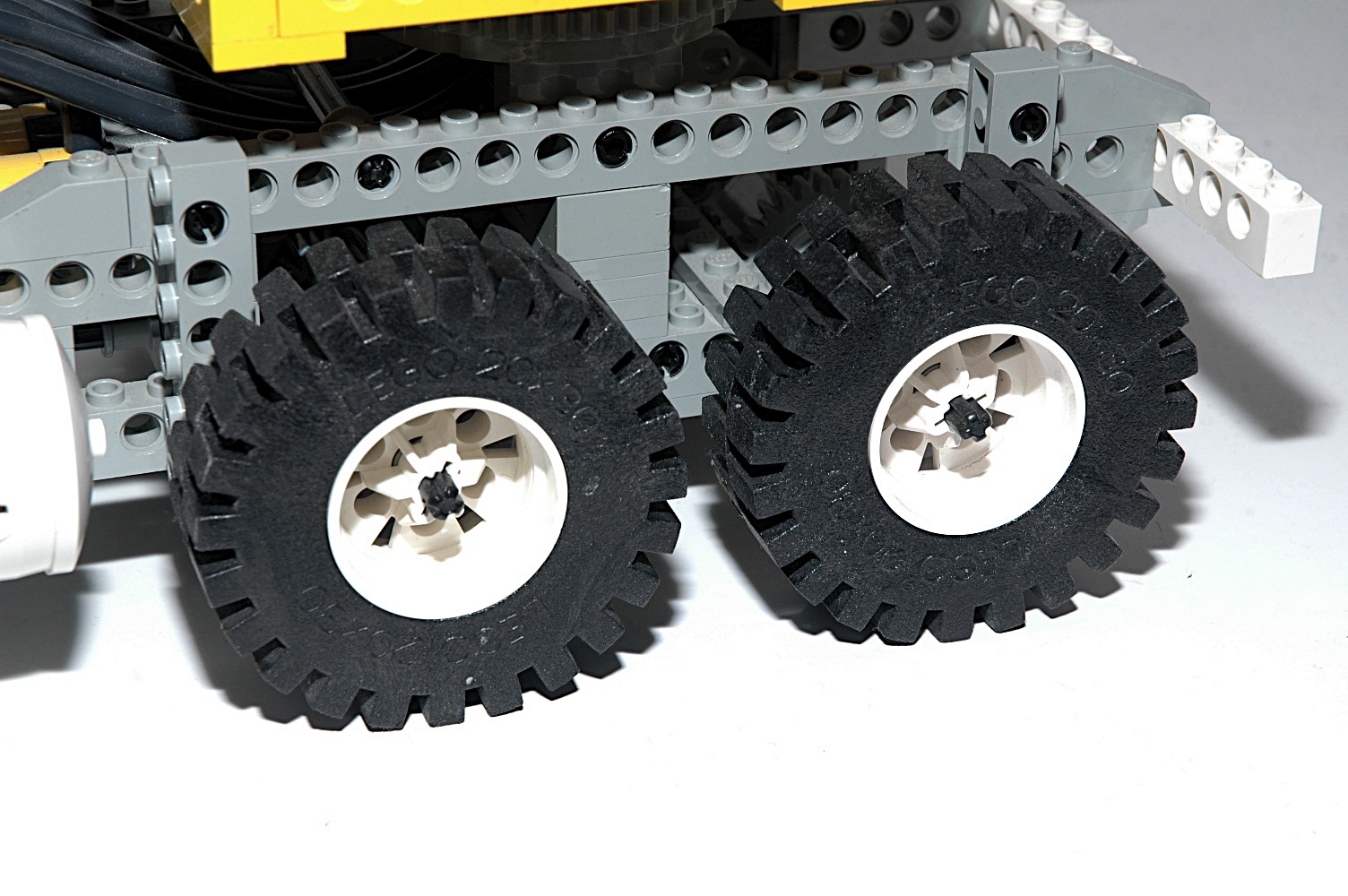
Wheels and Tires
This set uses six of the smaller size foam 20x30 tires and
wheels. While tandem rear wheels would have been nice, there is
no way they would have fit into the width of this model.
|

|


