TW-715 Project
Page 2: Building the Engine and Transmission
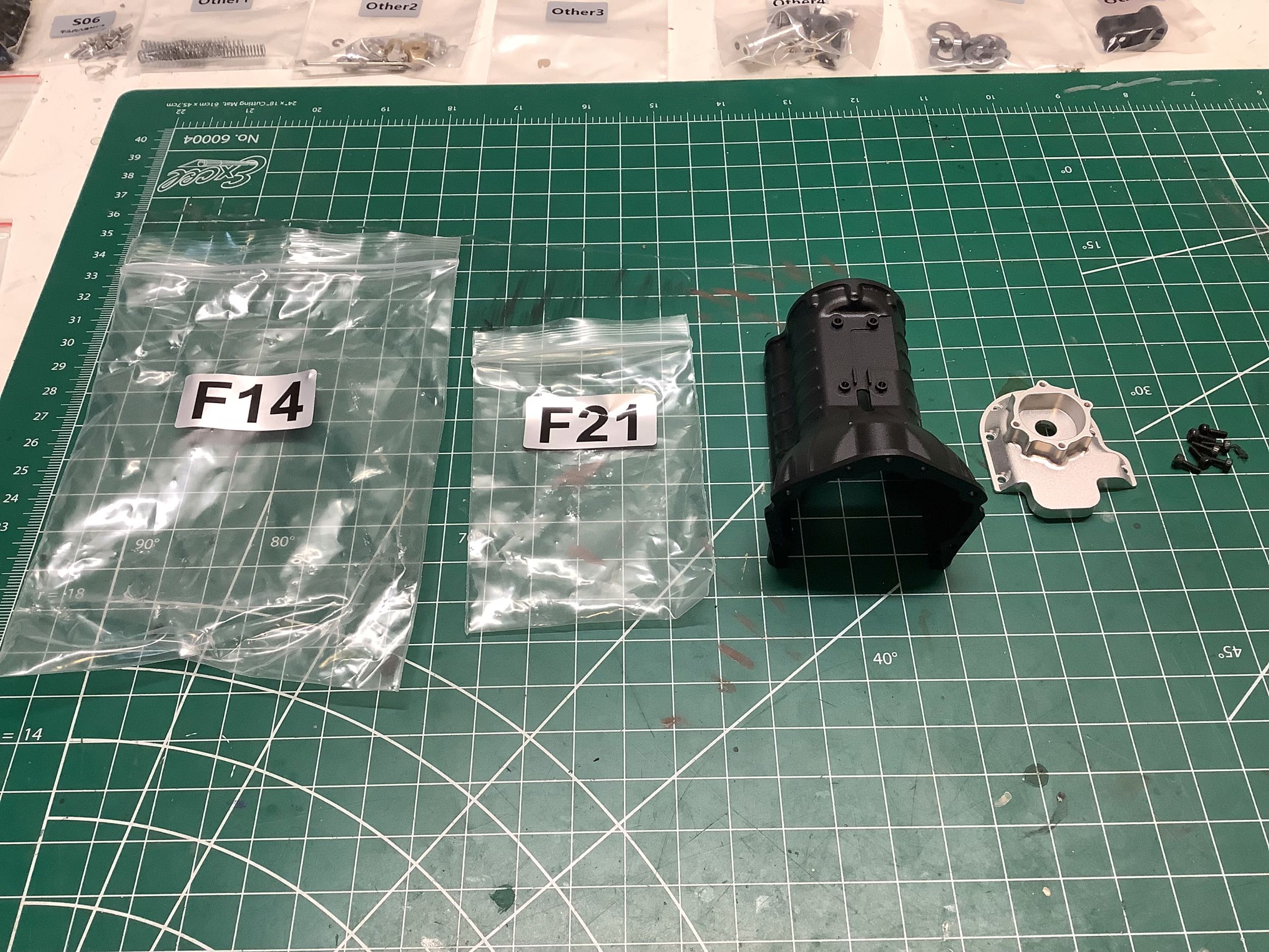
Time to start the build! I assumed that all those numbered bags
would be used in order, but that turned out not to be true at all.
For example, bags F14 and F21 are needed for the first step as
shown. The instruction videos actually don't even refer to the bag
numbers (except for the screws), so you just need to find the right
parts based on what they look like. I suspect the numbers are just
there to make it easier to fill out the checklists when packing the
boxes. The very first parts needed
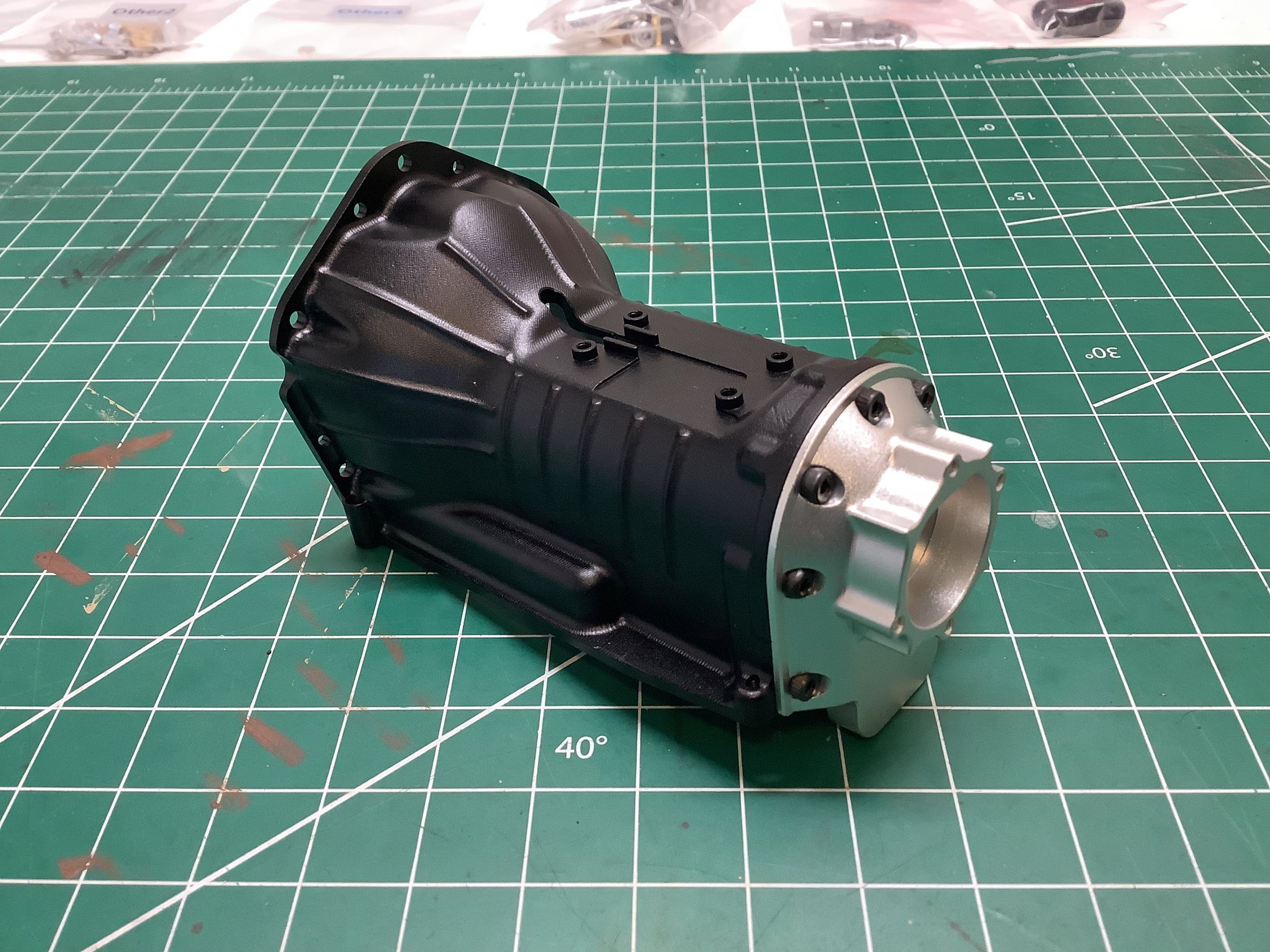
are the transmission bell housing and the rear seal, both machined
aluminum. If you zoom in on the photo you can see the cutter marks
on the bell housing confirming that it is machined and not cast.
I'm not quite sure why nearly all the engine and transmission parts are
clear anodized but the bell housing is black. Maybe just for some
contrast. 7 small cap screws are used to connect them together.
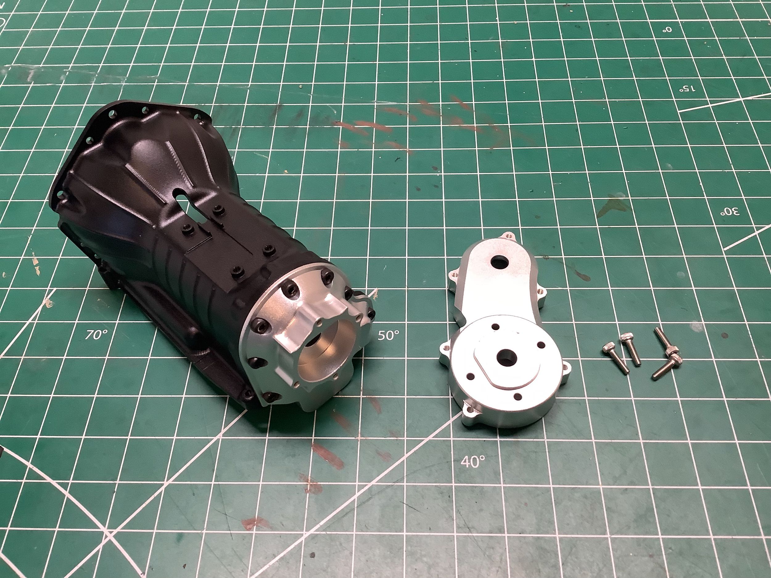
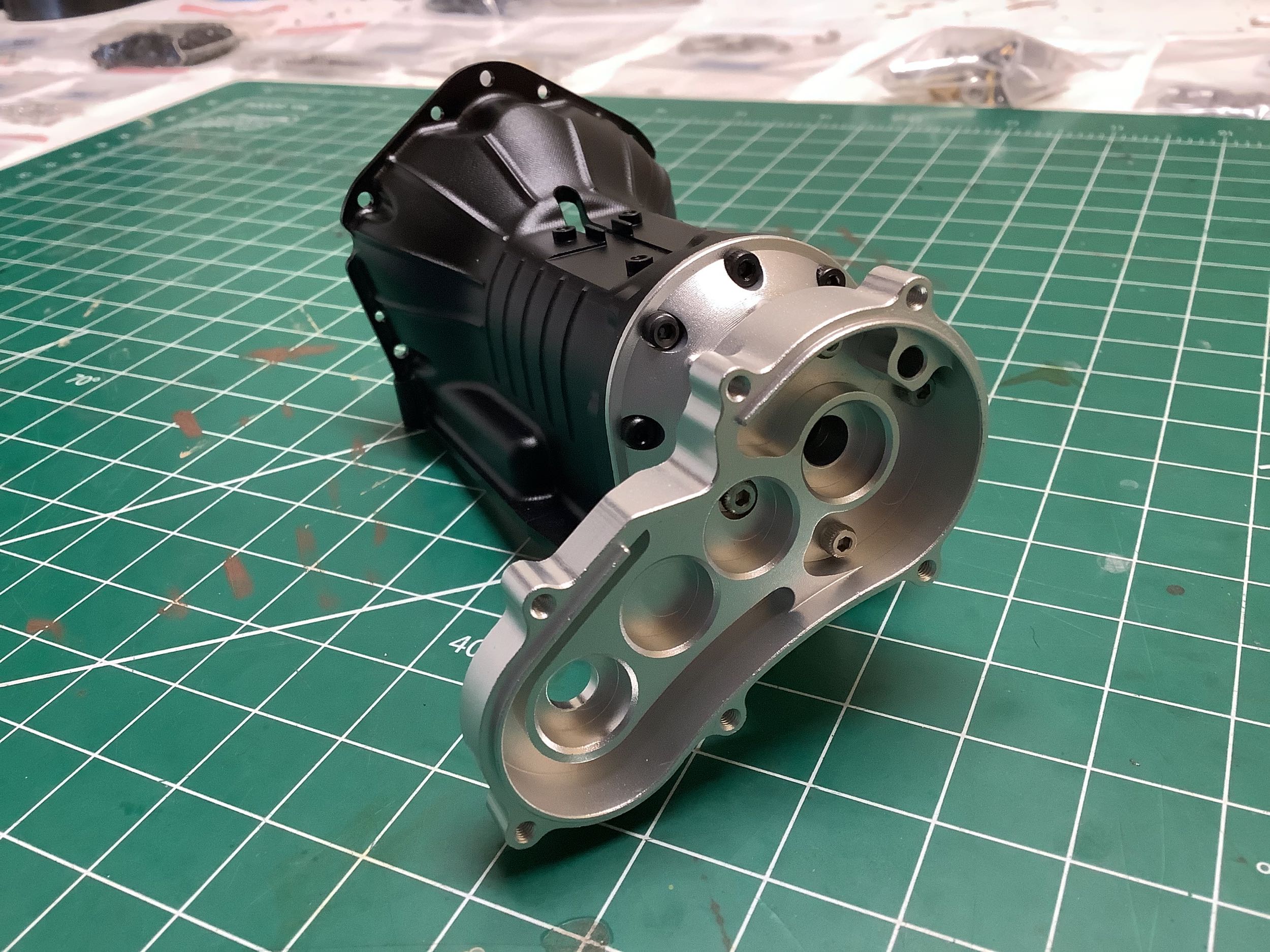
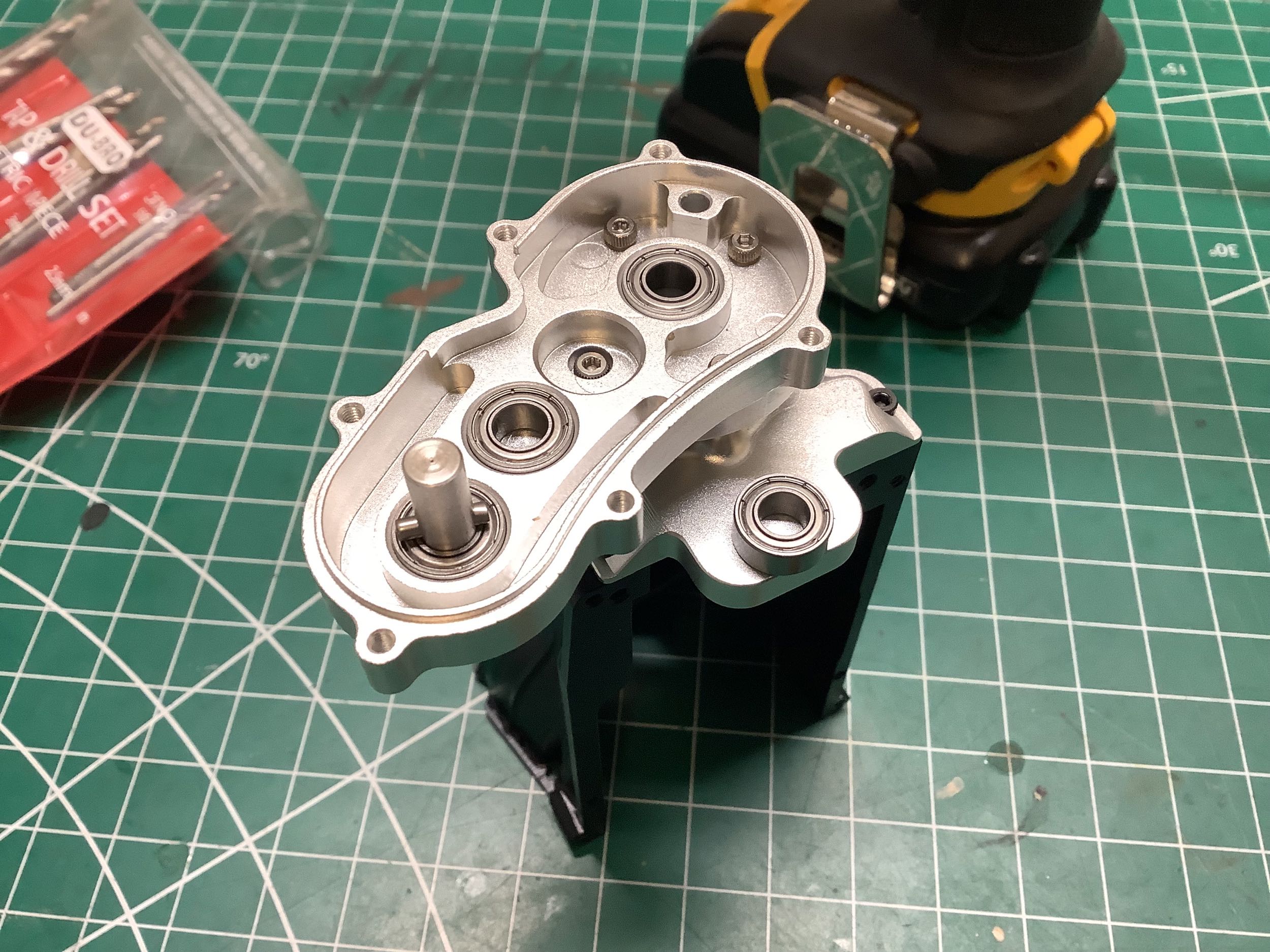
The next step is to connect the front housing of the transfer case to
the back of the gearbox. On the left you can see the round
indexing feature with one flat side on the transfer case housing which
is used to make sure it can only be installed in a single
orientation. There are 4 bearing recesses in the housing as you
can see on the right.
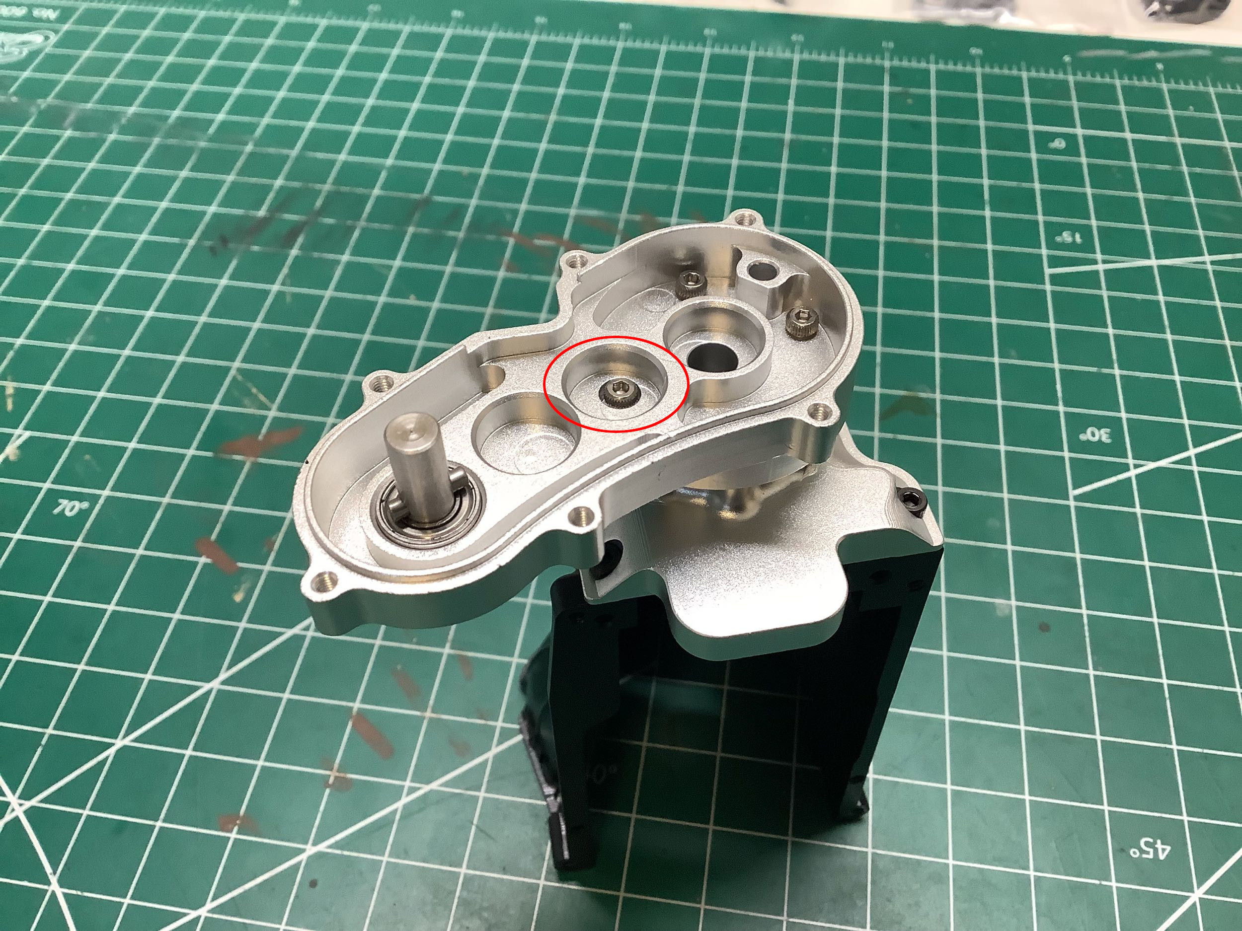
Here I ran into my first quality problem on the model only three steps
in. The hole for the screw circled in red on the left was not
tapped deep enough for the screw to be inserted completely. With
the screw standing proud, the bearing could not be installed flush and
therefore the whole transfer case just jammed up once screwed
together (which is how I discovered the problem). I had to manually drill and tap the hole deeper with an
M2 tap to solve the problem (corrected on the right).
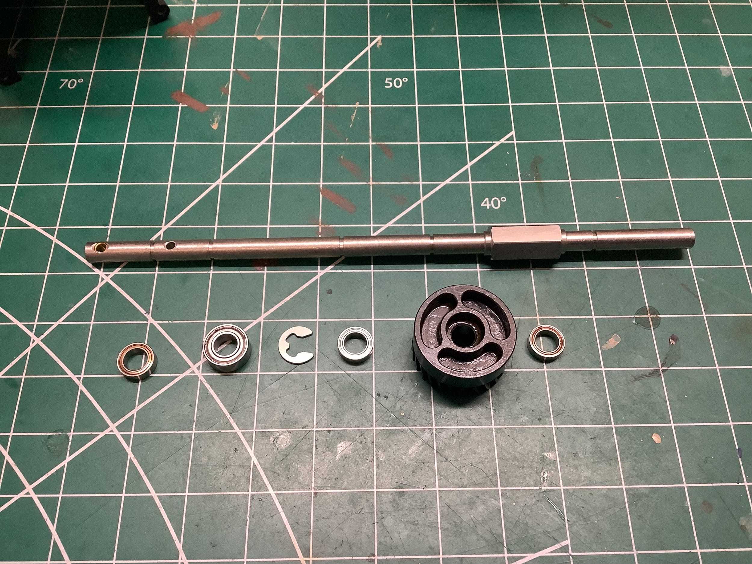
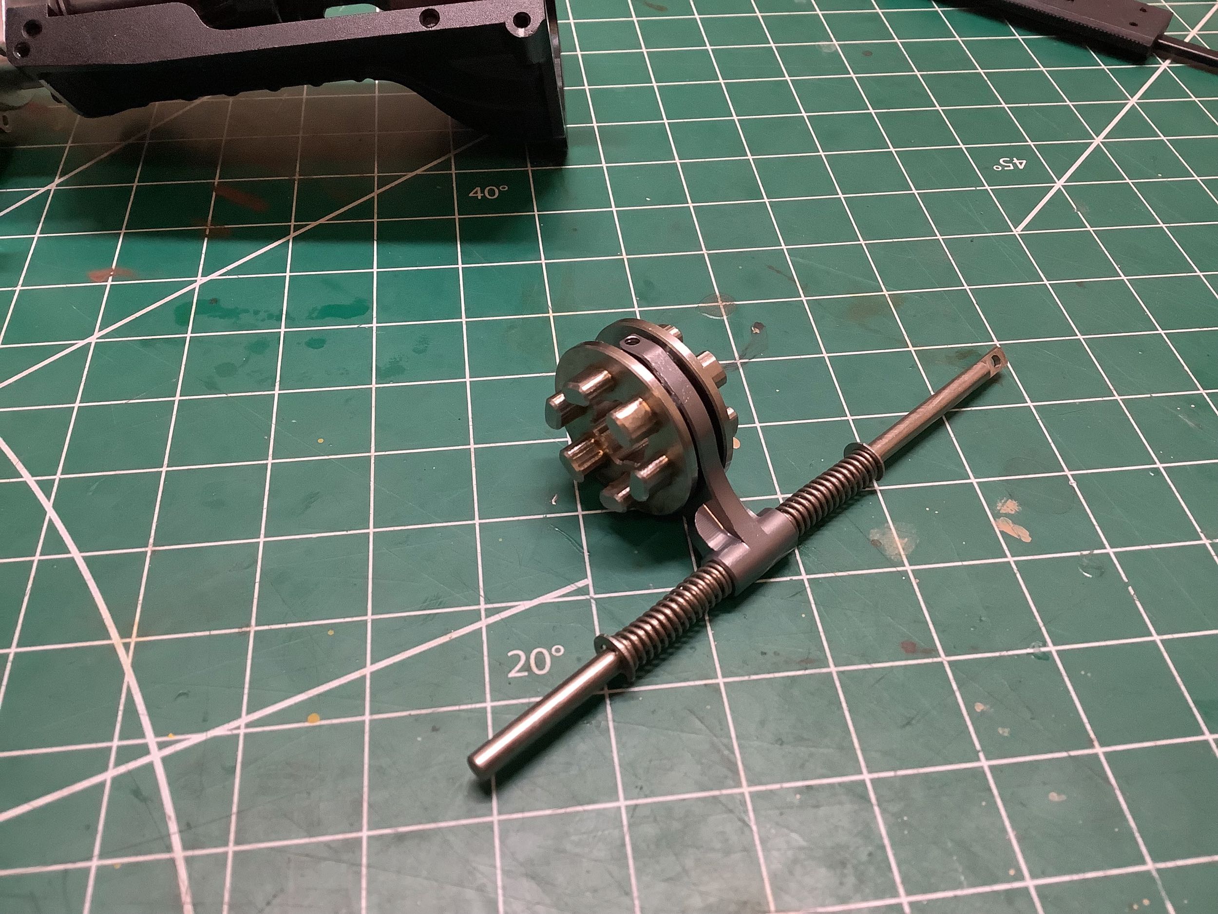
Now we'll build the gearbox output (driven) shaft. Both of the
gears which will eventually be on this shaft are on bearings and
therefore can rotate freely and independently of the shaft speed.
Only when the driving ring keyed to the central hex is engaged with one
or the other of the gears will the shaft be driven. The three curved
slots seen on the back of the gear on the left will be engaged by dogs
on the driving ring. If the driving ring is centered (not engaged
with either gear), then the gearbox is effectively in neutral meaning
that the motor can spin freely without any connection to the
wheels. Note that all of the gears within the main gearbox are
helical. Helical gears run smoother than straight cut spur gears
but are also noisier. The whine of this gearbox is very distinctive
once you know what to listen for.
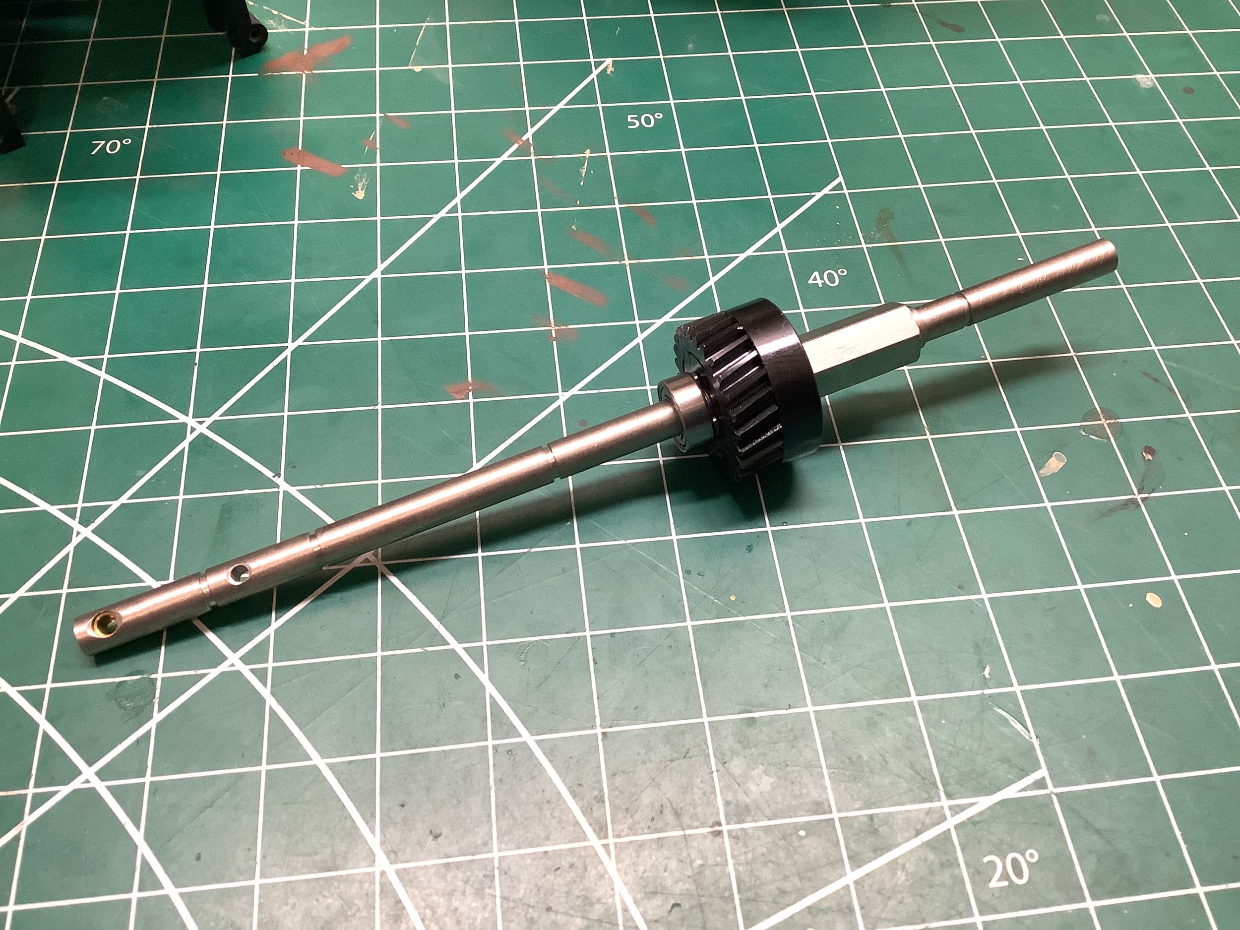
This gear is used for high speed operation and appears to have 26
teeth. I didn't count the teeth before assembling the model so I
am relying on pictures (including the instruction video).
I should mention a clear Capo tie-in here. As far as I can tell,
these transmission gears are the identical parts that are used in the
Capo 15827 JK Max. Both gearbox configurations use a layshaft.
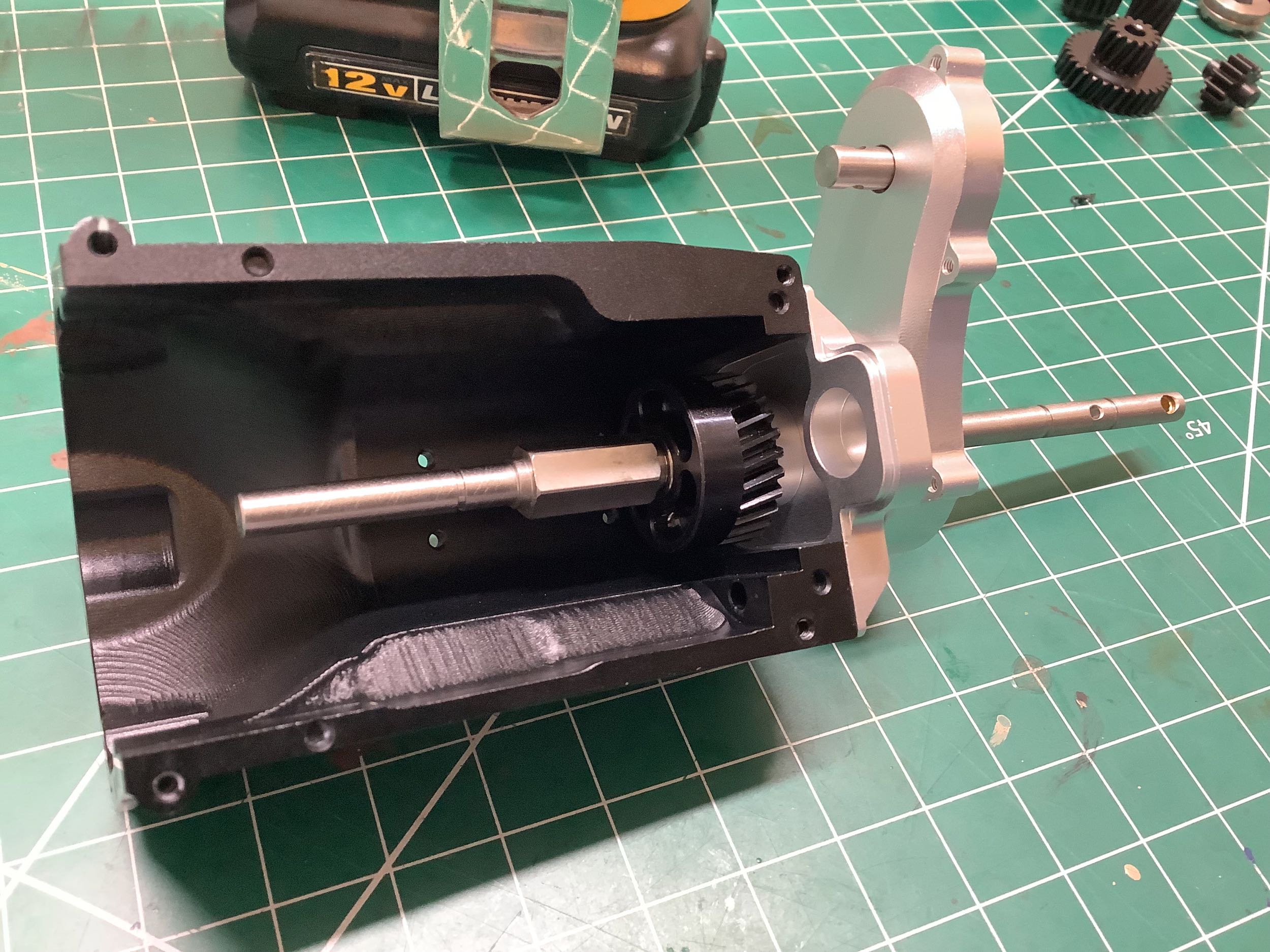
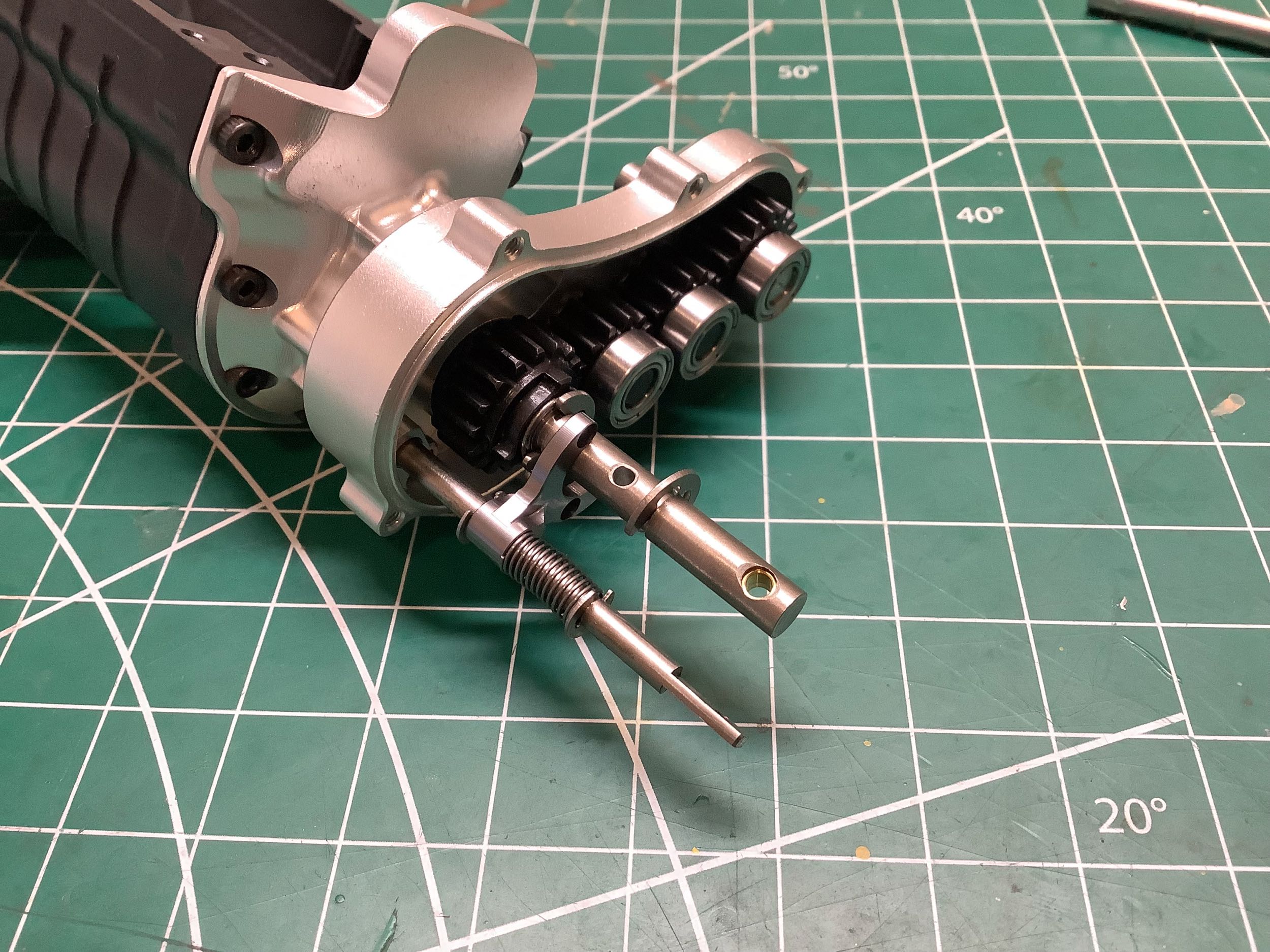
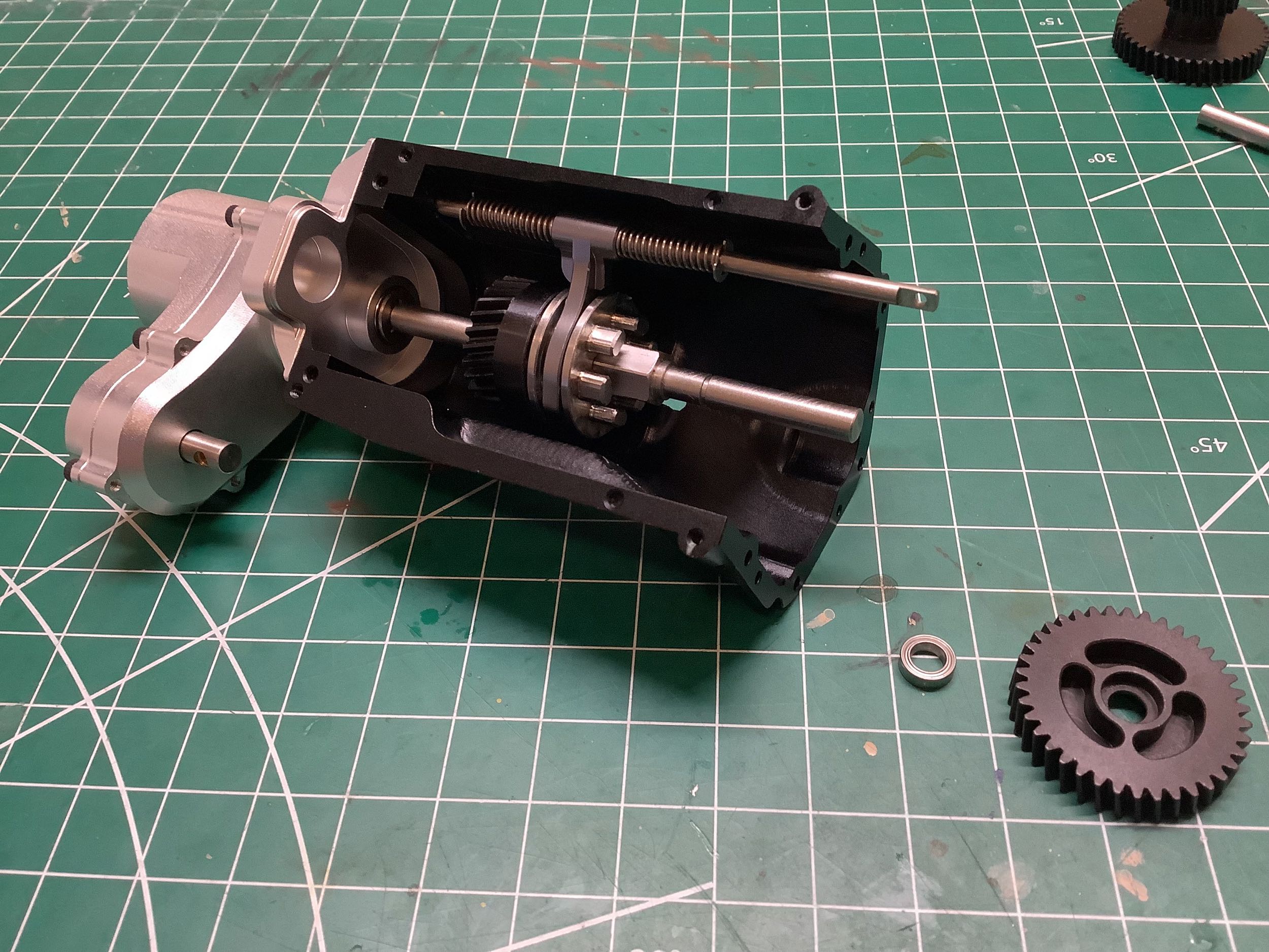
Now I've installed the output shaft into the gearbox housing. You
can see that it protrudes straight through the transfer case and will be
used to directly power the rear drive shaft. There are four
straight cut spur gears inside the transfer case as shown on the
right. The two intermediate idler gears have 14 teeth. The
two larger outer gears have 17 teeth. None of
these tooth counts really matter since everything cancels out resulting
in a 1:1 ratio between the front and rear axles. The gear to the
far left of the image is used to power the front drive shaft which,
because there an even number of gears, rotates the opposite direction as
the output shaft. A close look at the gear on the far right (on
the output shaft) shows that it is not locked to the shaft but has three
driving dogs. This means the transfer case will only power the
front wheels when something is locked to this gear. More on that
later.
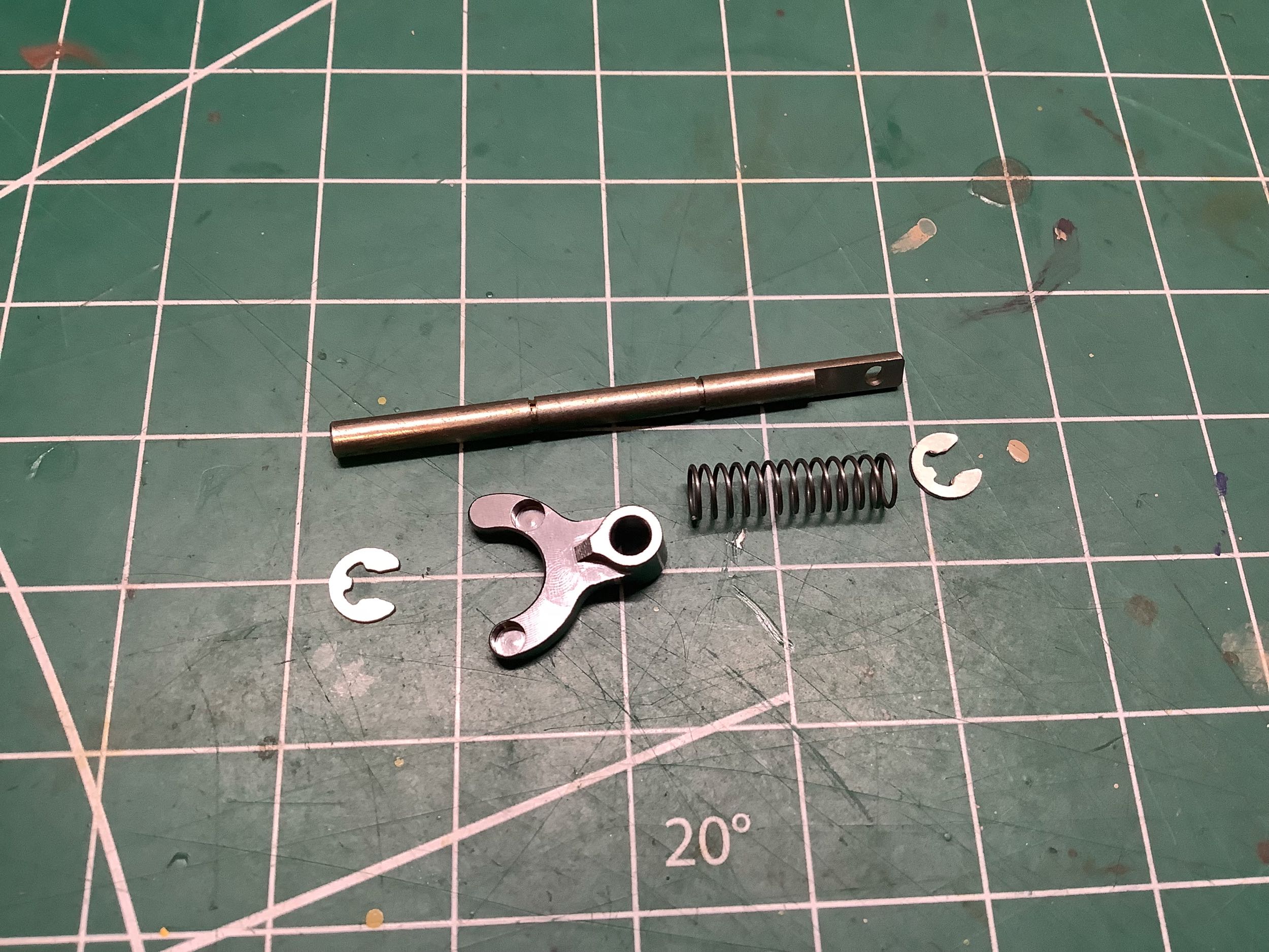
This little shift fork controls the 2WD/4WD selector which is built into
the transfer case as described above. The spring tends to keep
the t-case in 2WD unless something is forcing it into 4WD. Because
the driving ring will have to rotate relative to the fork, the fork
contains 4 pockets for ball bearings. I did not install the balls
yet at this point due the missing part described below.
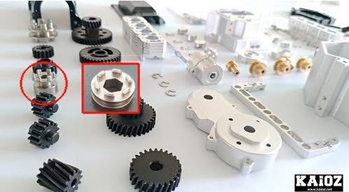
Here I ran into an extremely frustrating problem. The driving ring
I needed for the t-case selector was not in the kit. A part which
looks quite a bit like it was included instead (packing error).
The error is detailed in the photo I made on the right. The
circled part is what I needed, the boxed part (which is actually for the
locking differential) is what I got. Luckily Sumi and Kai-Oz.net
sent the correct part out to me right away, but it meant I had to either
stop building or find a way to continue without it. As shown on
the left, I was able to just leave the part out for now which resulted
in RWD only. Because I knew I was going to have to tear down the
transmission later to install this part, I didn't grease any of the
gears yet (which also makes for better photos).
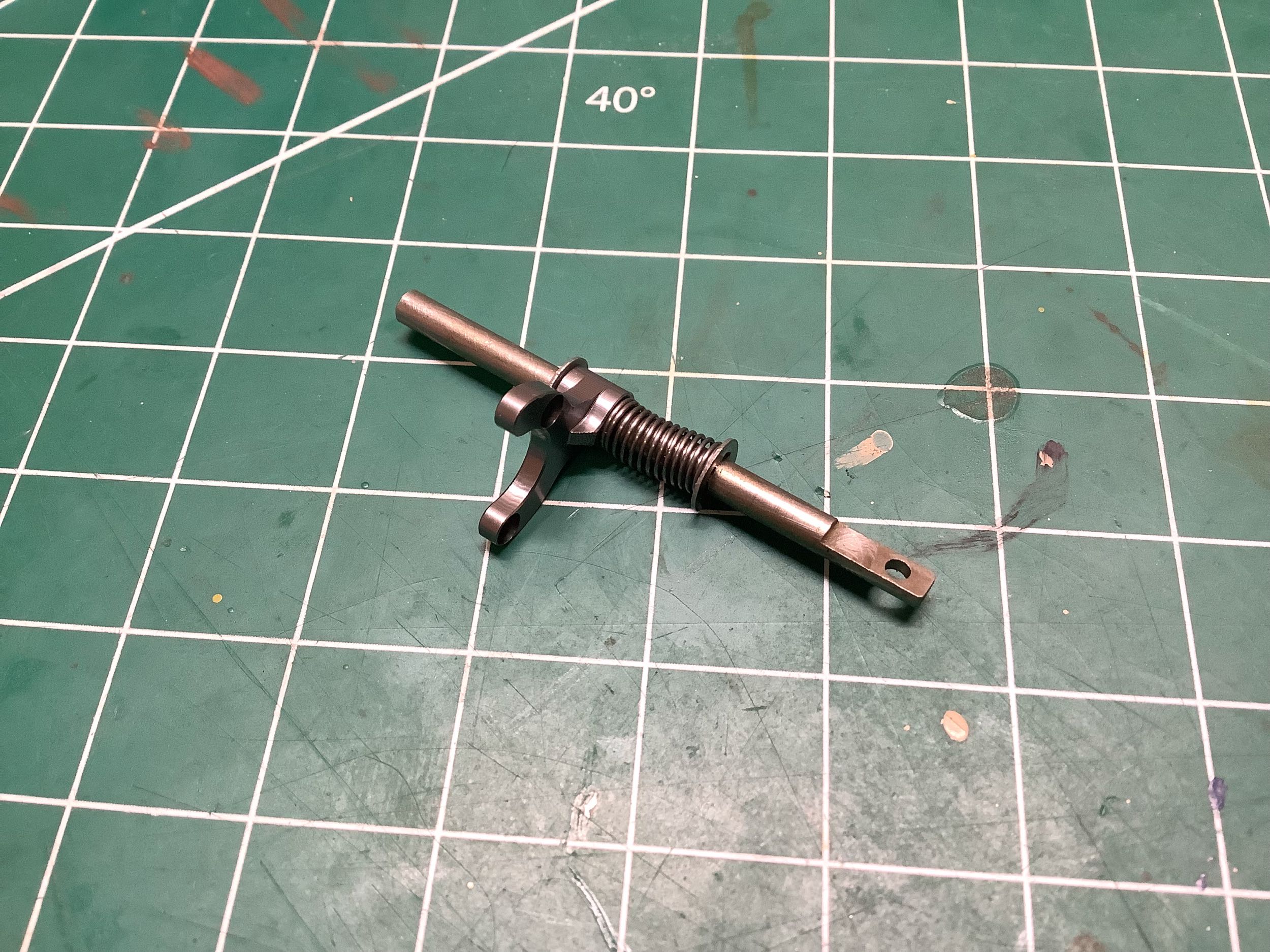
Here I'm installing the t-case rear housing without the driving ring
installed. Once it is buttoned up with the six cap screws shown,
you can't even tell anything is missing. The little hole in the
shaft on the shift fork will be used to connect to a mini-servo linkage
for controlling the t-case.
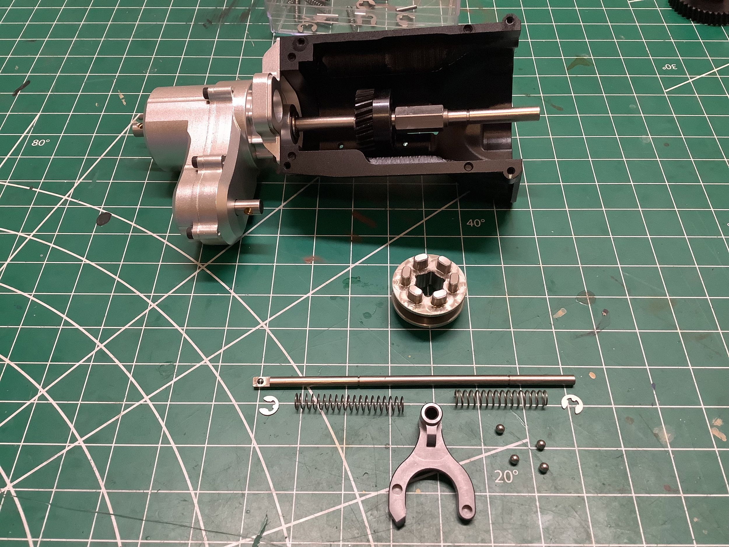
Now we can start building the primary shift fork. This works very
much like the smaller one with 4 ball bearings in the fork. This
fork is spring loaded to center which means the transmission will be in
neutral unless forced into either high or low gear. Note the six
driving dogs on either side of the drive ring which will engage with the
three slots in the mating gears.
Now I can slide the low speed gear onto the out shaft. This heavy
steel gear has 38 helical teeth and rides on two ball bearings as
shown. Note that it has 3 slots facing the driving ring just like the high speed
gear.
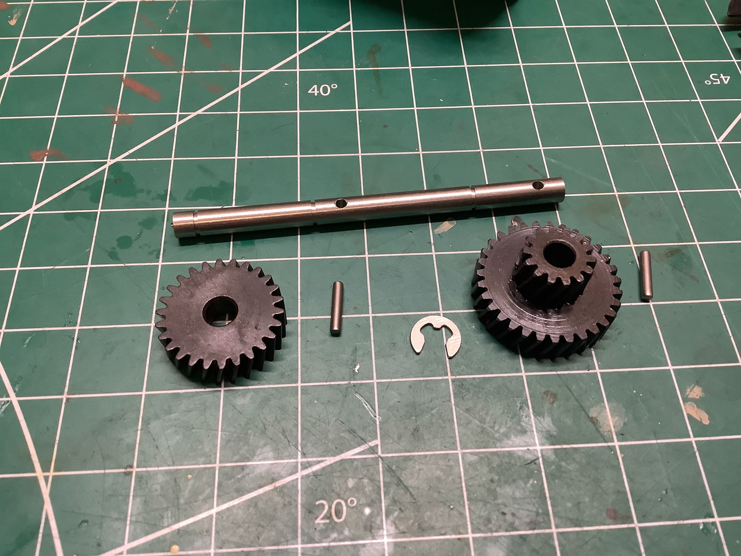
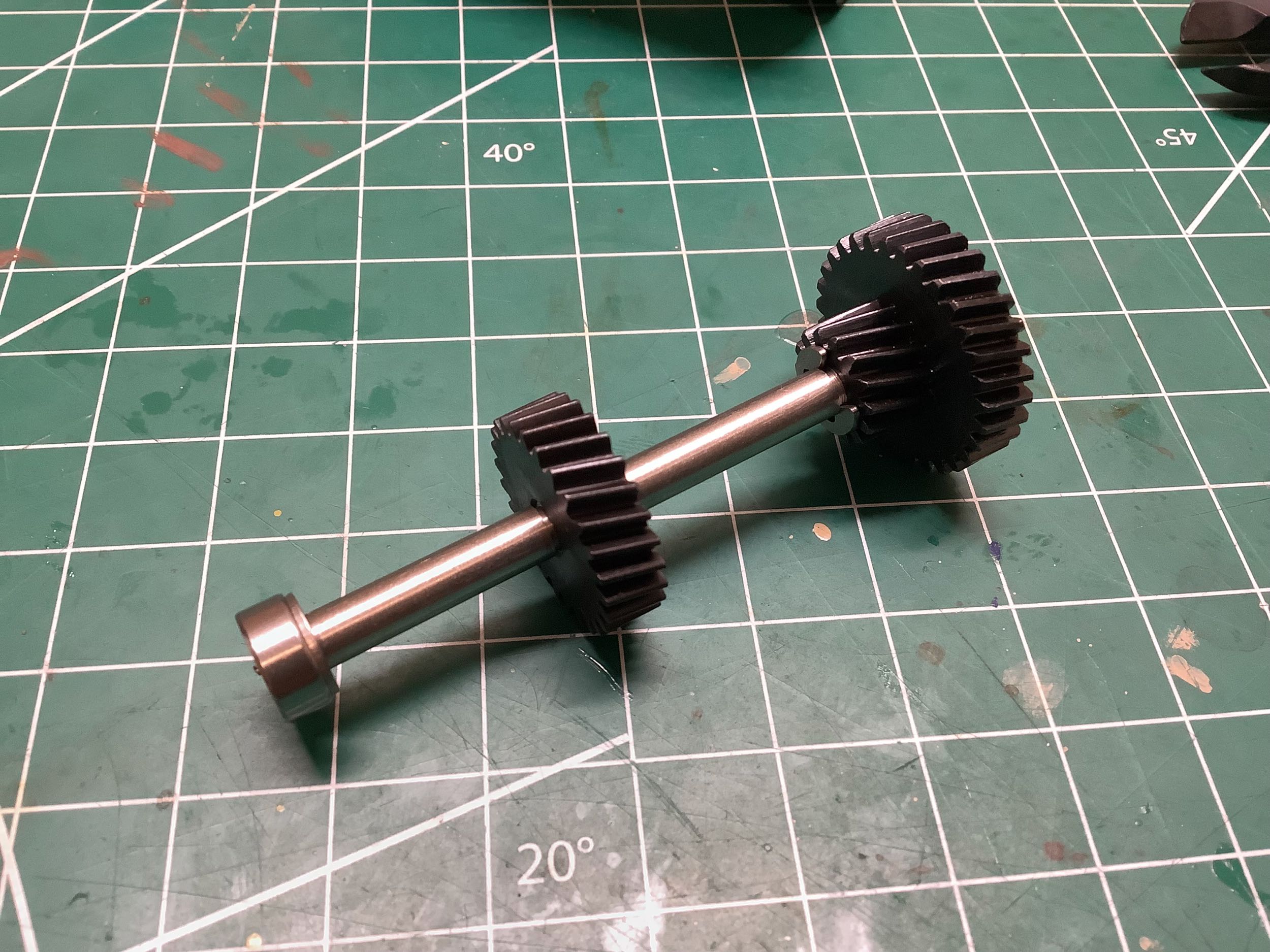
Now we'll build the layshaft. The presence of two cross pins tells
us that both gears are going to be locked to the shaft. The gear
on the left is the high speed driver and has 26 teeth which means high
gear is 26:26 = 1:1. The smaller gear on the right has 14 teeth
which results in a ratio of 38:14 = 2.71:1. That's a big
difference between high and low gear (as it should be for something used
on the trails). The larger gear on the right drives the layshaft
and has 31 teeth.
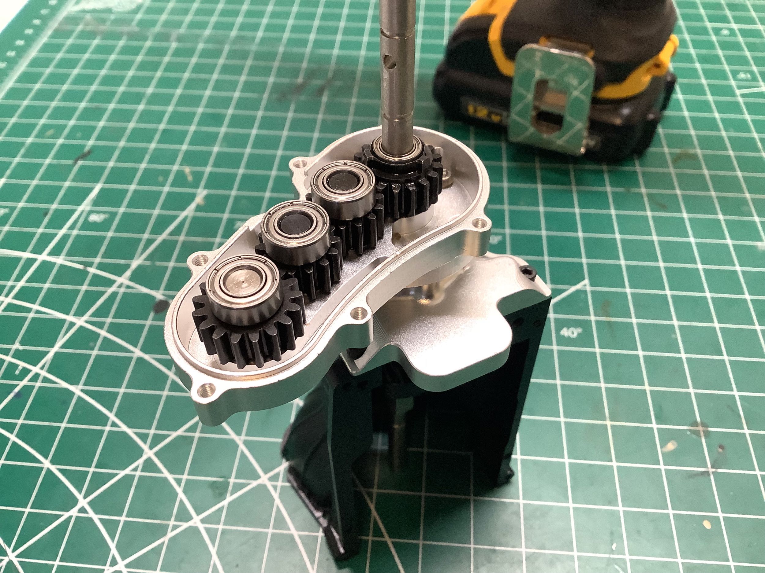
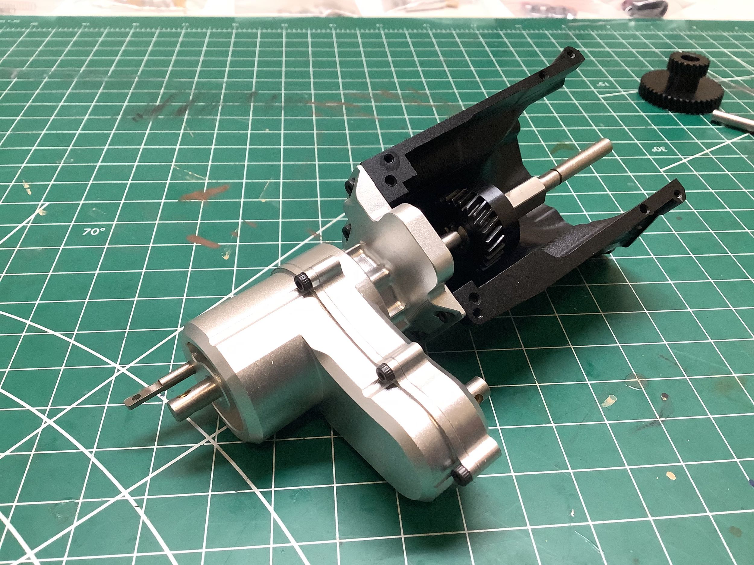
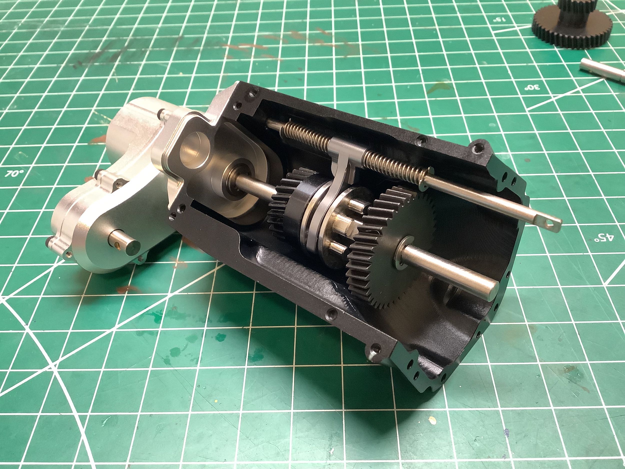
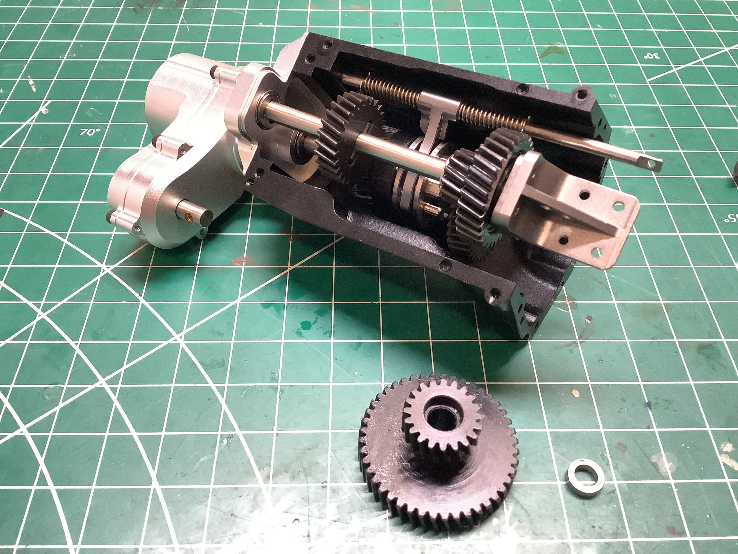
Now the layshaft has been installed into the gearbox housing, but we're
not done gearing down yet. Let's another stage of reduction.
The gear shown on the lower left will ride on the output shaft, but not
be keyed to it. The larger diameter 44 tooth gear acts as the
motor spur and the smaller diameter 20 tooth drives the layshaft.
The layshaft ratio is 31:20 = 1.55:1.
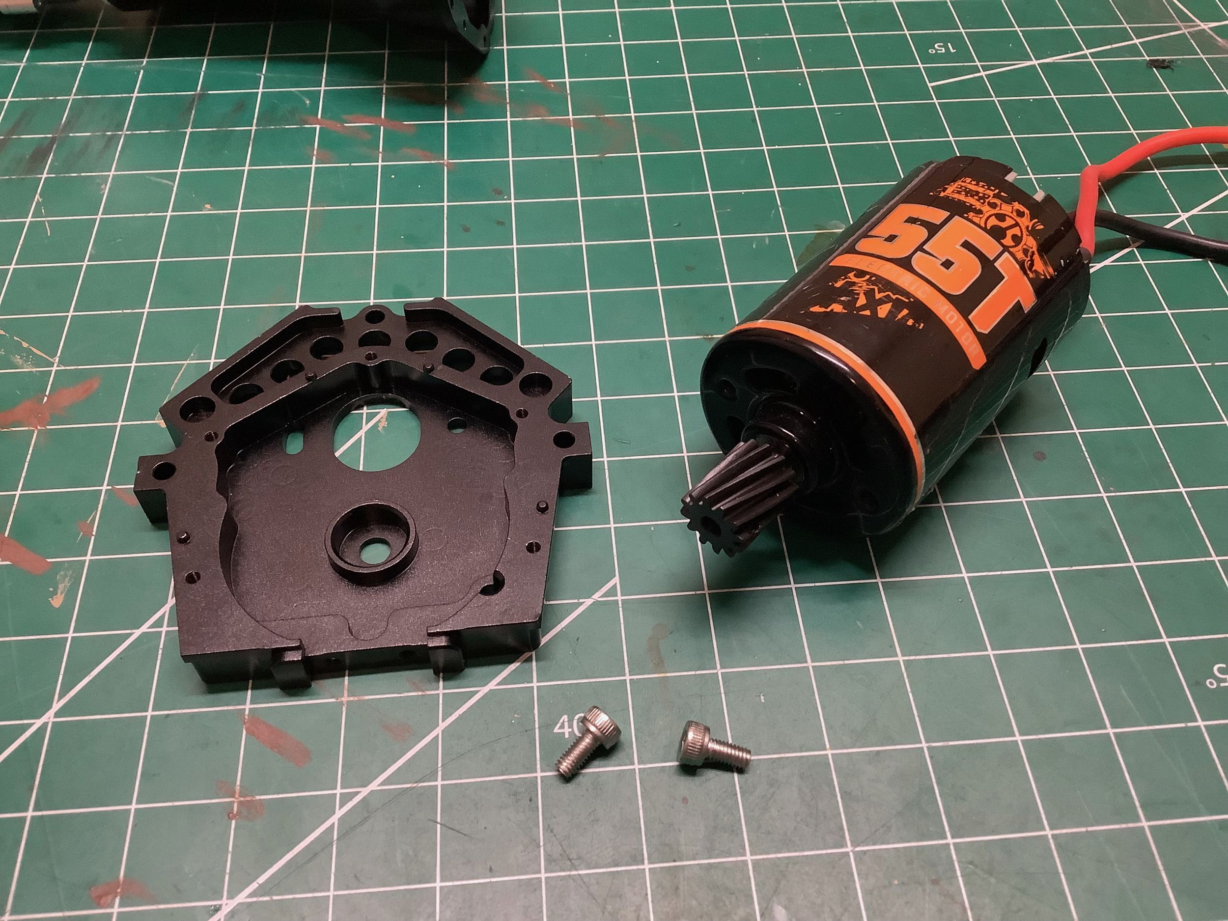
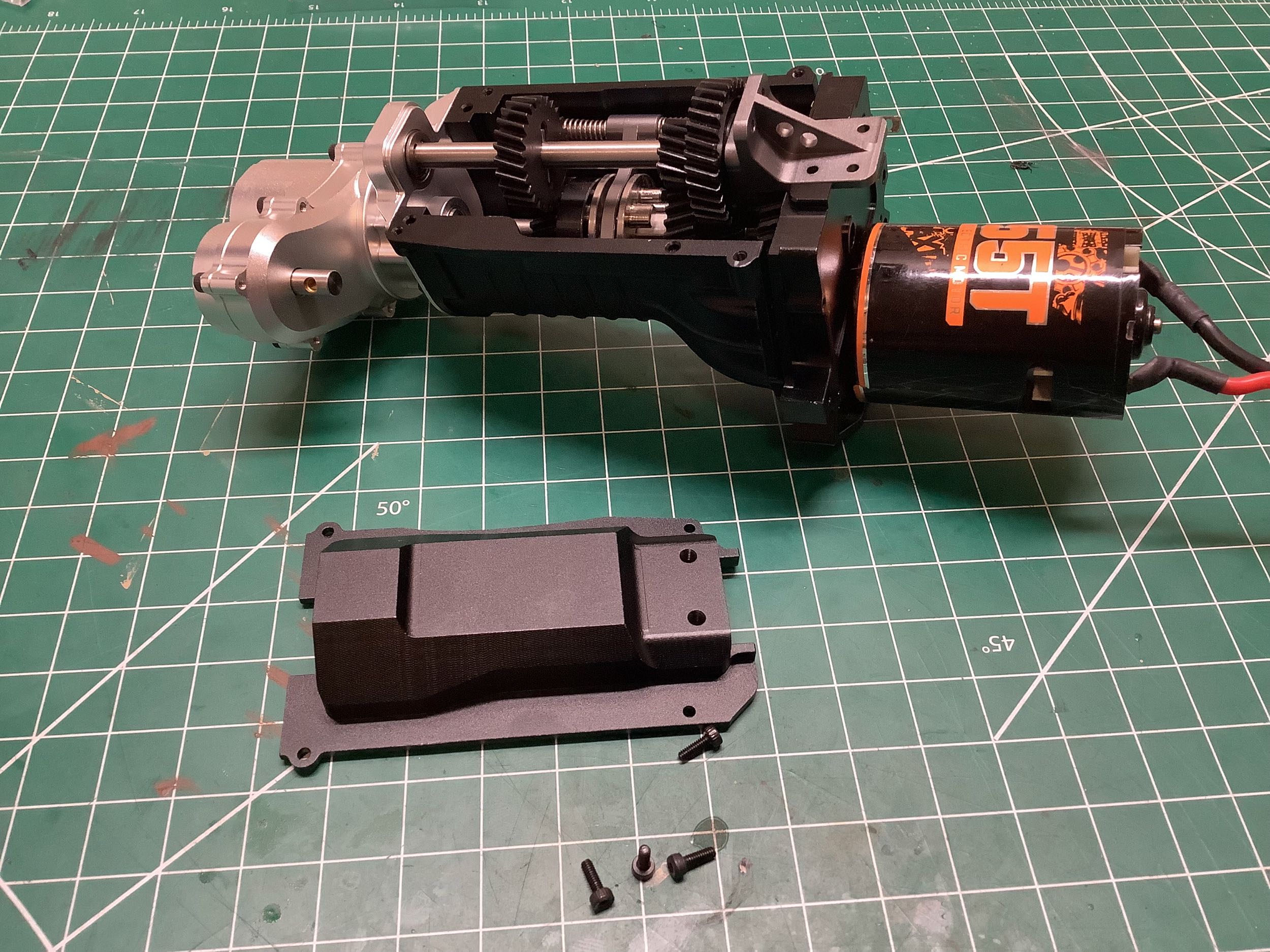
The cheap Axial 55T motor shown is just a placeholder until my Holmes
Hobbies motor shows up. Remember, I have to tear down this gearbox
to add that missing driving ring anyway. The helical cut motor
pinion has 12 teeth, so the motor drive ratio is 44:12 = 3.67:1.
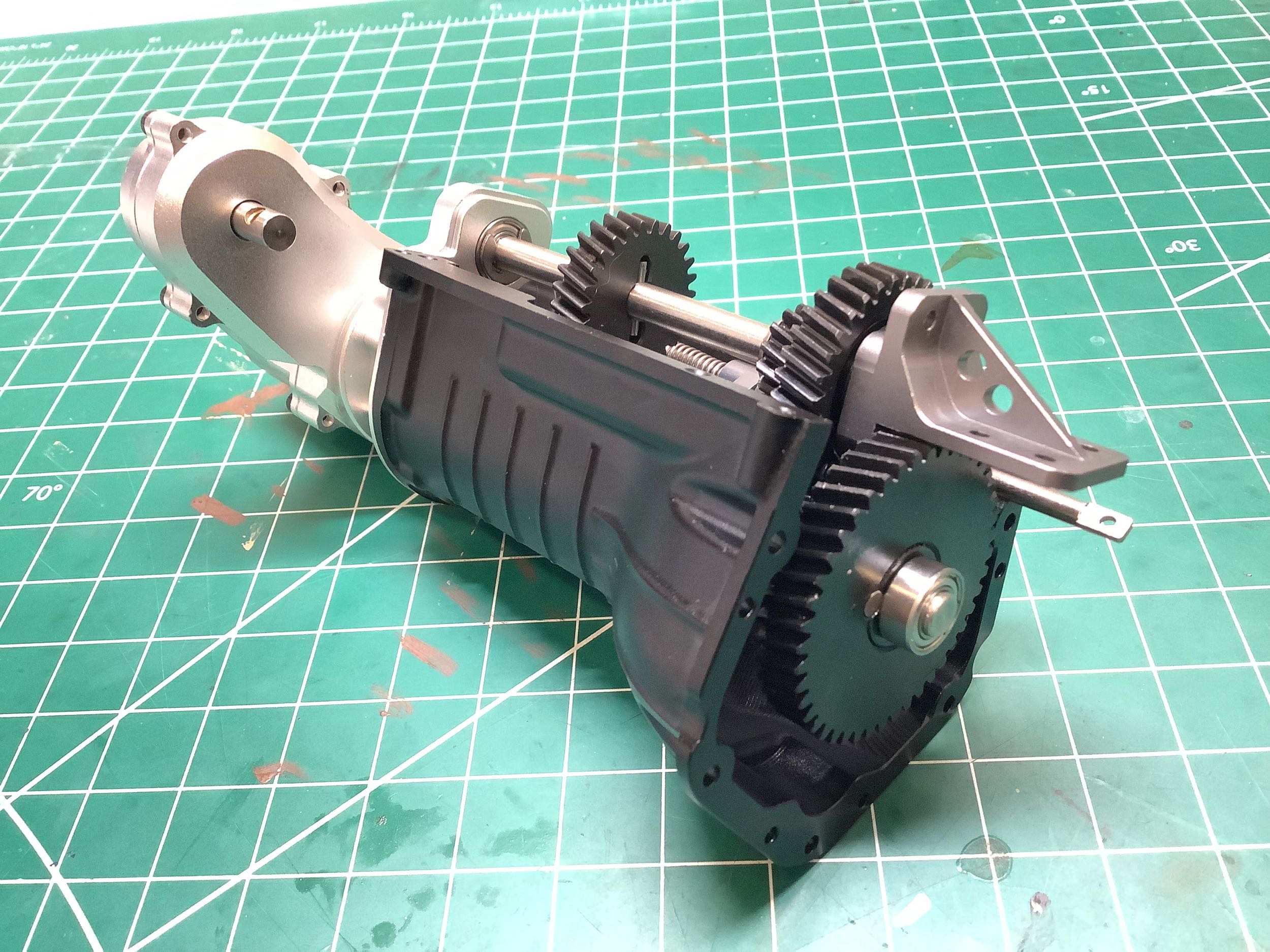
Let's install the oil pan with four cap screws and then calculate the
overall transmission ratios.
- Low gear = 44:12 x 31:20 x 38:14 = 15.43:1
- High gear = 44:12 x 31:20 x 26:26 = 5.68:1
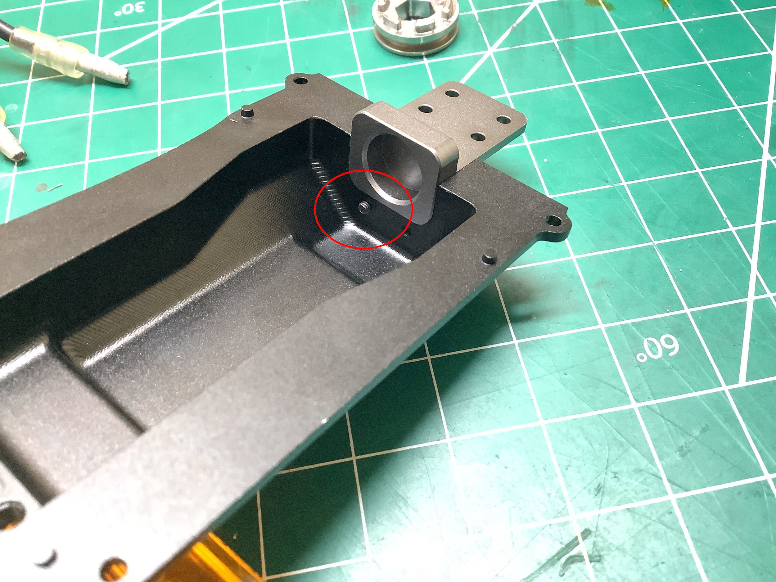
Time to connect a battery and see how this thing works! It
doesn't. The motor just stalls. It took me quite a while to
figure out the problem and it is shown circled on the right. The
screws which hold the front bearing support to the oil pan are too long
and protrude into the cavity. They then interfere with the
adjacent gear and prevent anything from moving. I'm amazed that
this design made it into production because it is impossible to operate
the model using these screws. There were no appropriately shorter
screws among the hardware provided so I just cut off about 1.5mm from
each screw with my Dremel tool and the problem was solved.
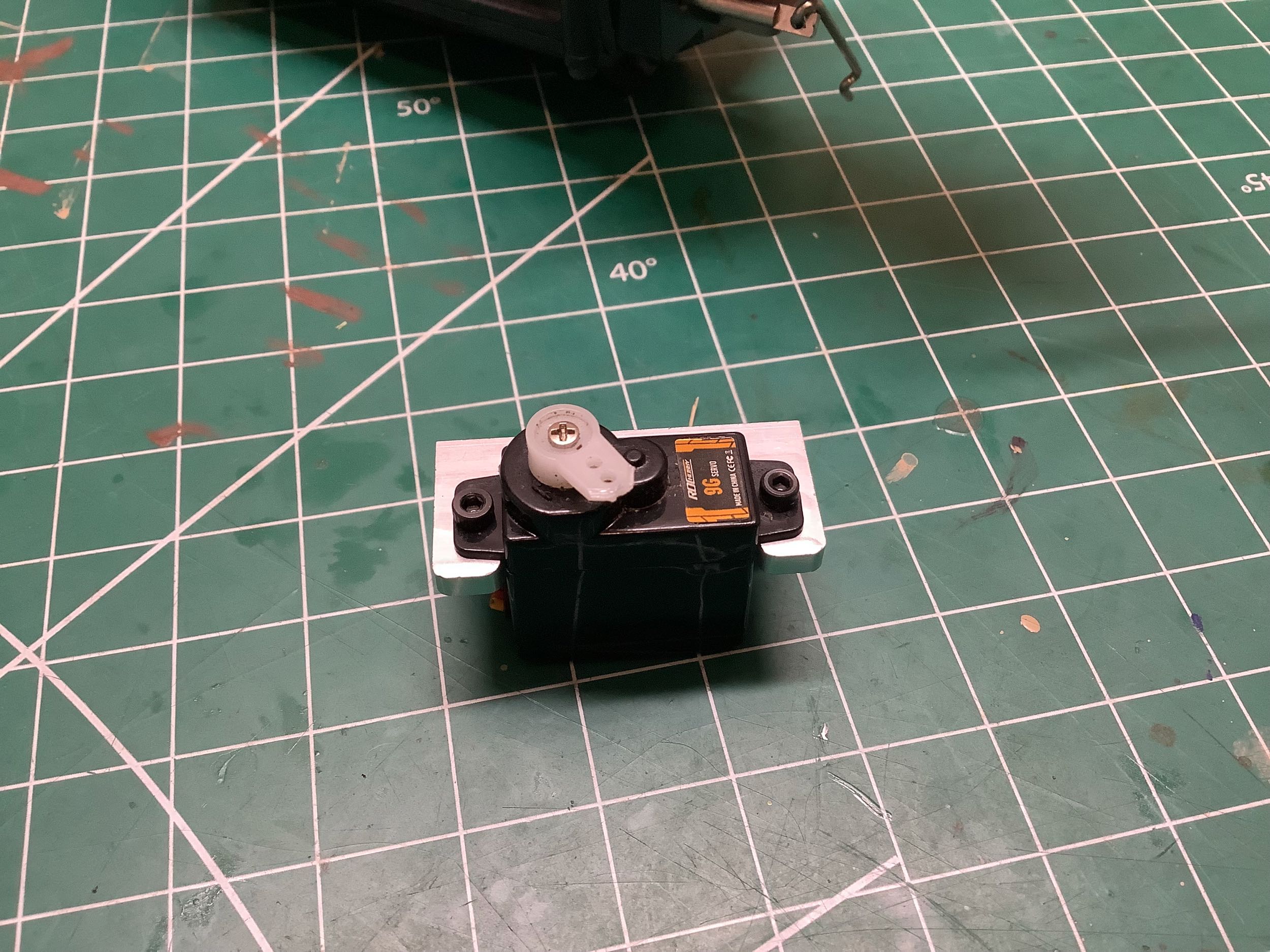
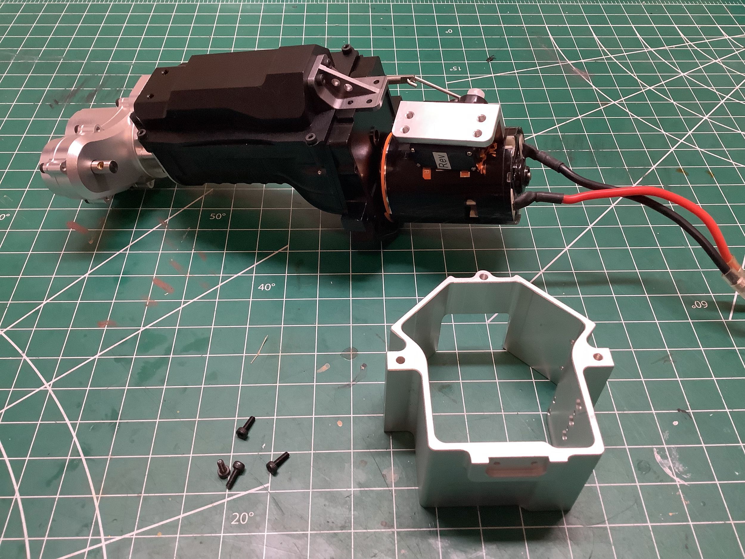
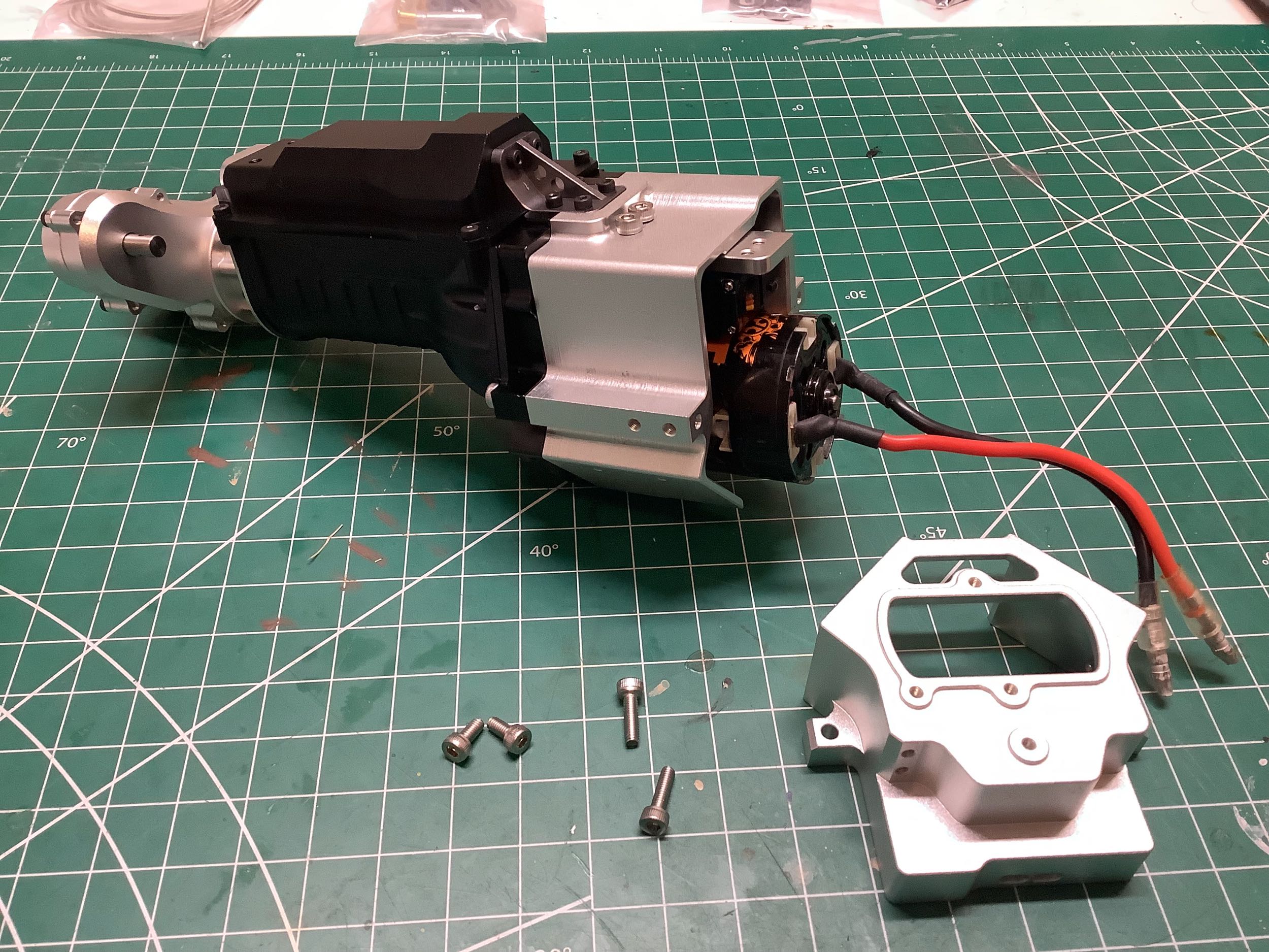
In keeping with my tradition of building this thing before I had all of
the necessary electronics, I'm using an old seized micro servo as a
placeholder until the new ones arrive. This servo controls the
high/low gear selector of the transmission and mounts inside the engine
block right beneath the motor as shown.
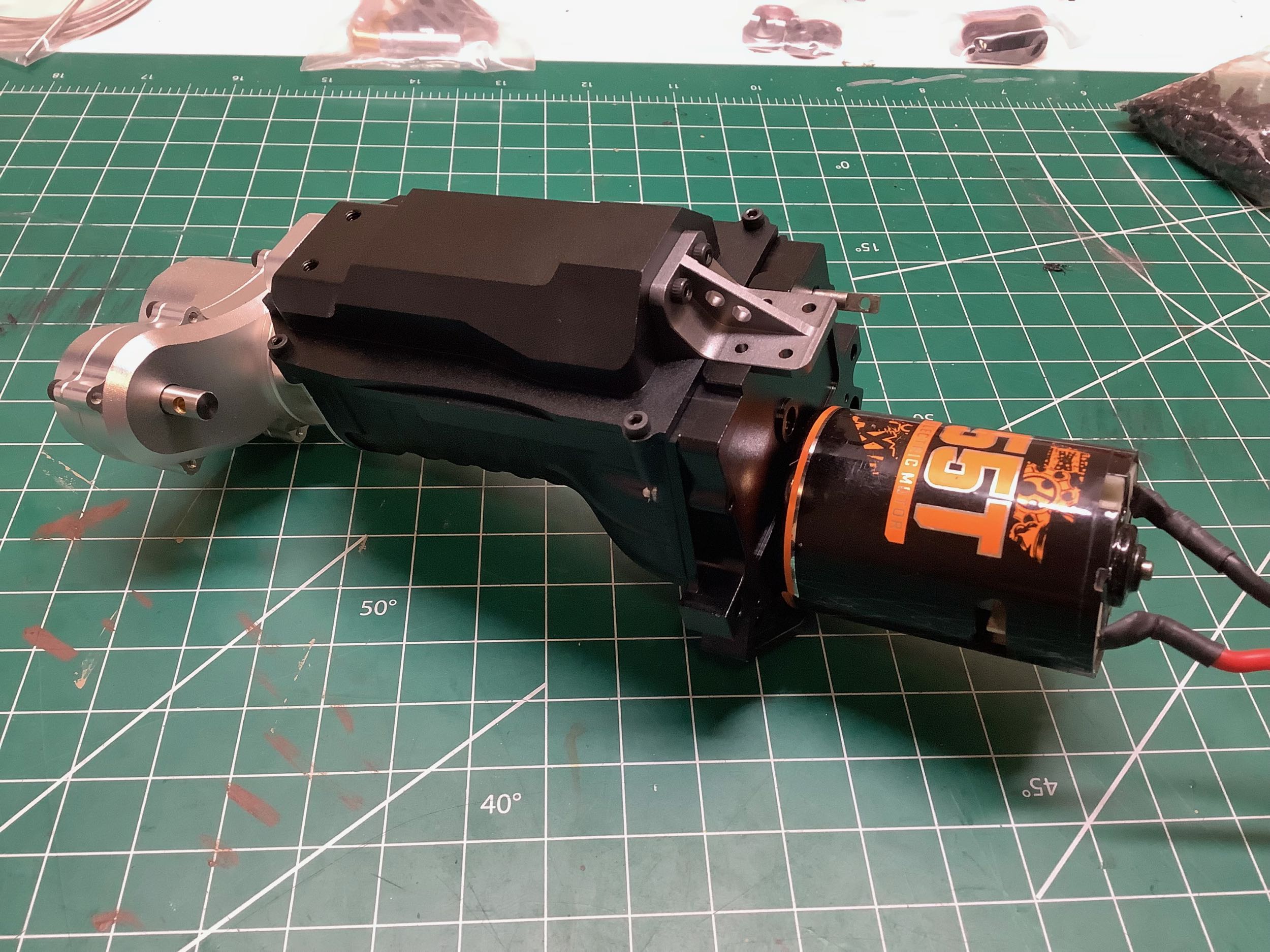
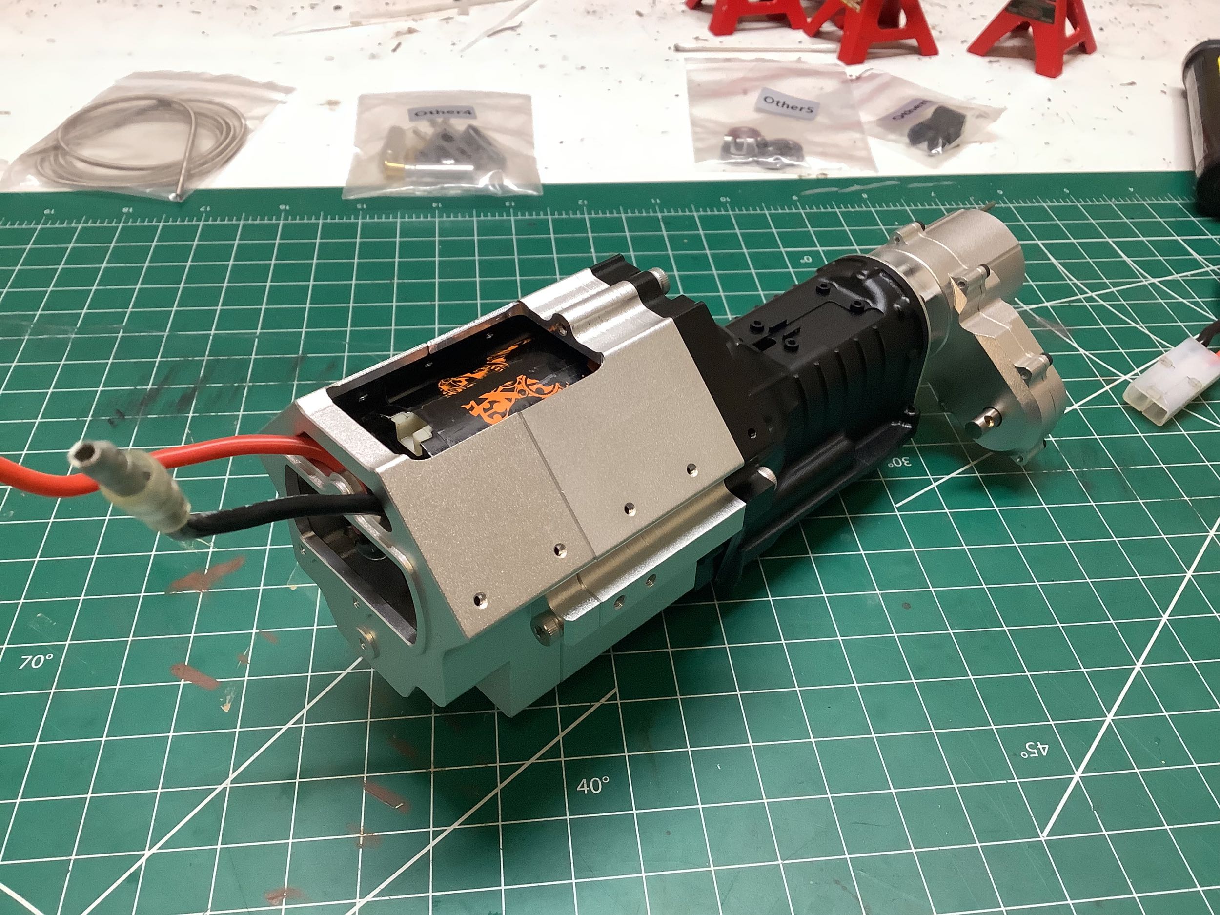
With the shift servo installed, I can start installing the two machined
housings which make up the engine block. As you can see, there are
openings on the front and the top. The slot that I'm currently
using for the wires is actually not correct, I should be running them
through the top opening to be hidden by the intake manifold. I'll
fix that when I install the correct motor later. At this point it
is possible to connect a battery to the motor and try everything
out. It works just fine apart from the front drive shaft output
which is waiting on that missing drive ring.
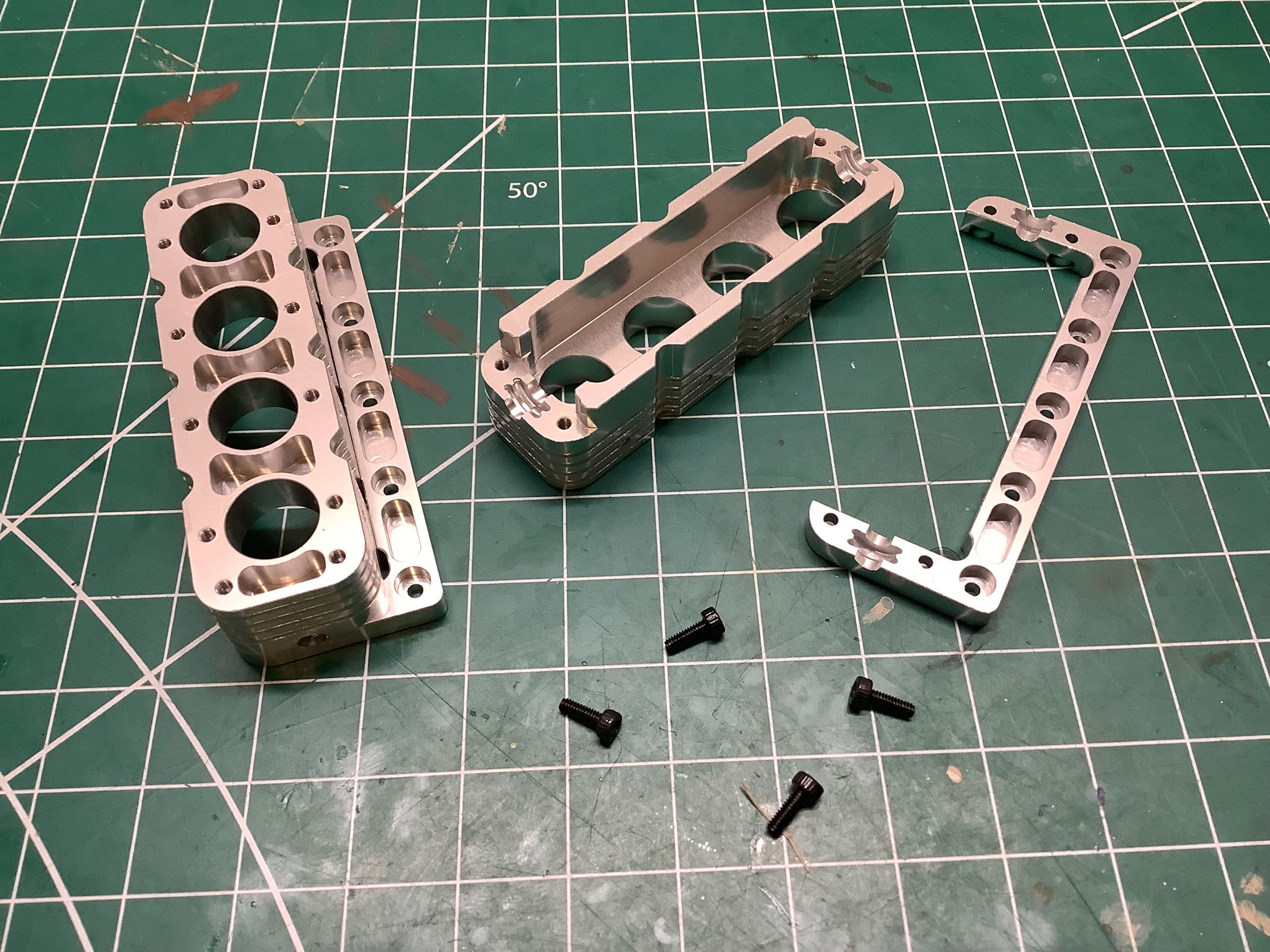
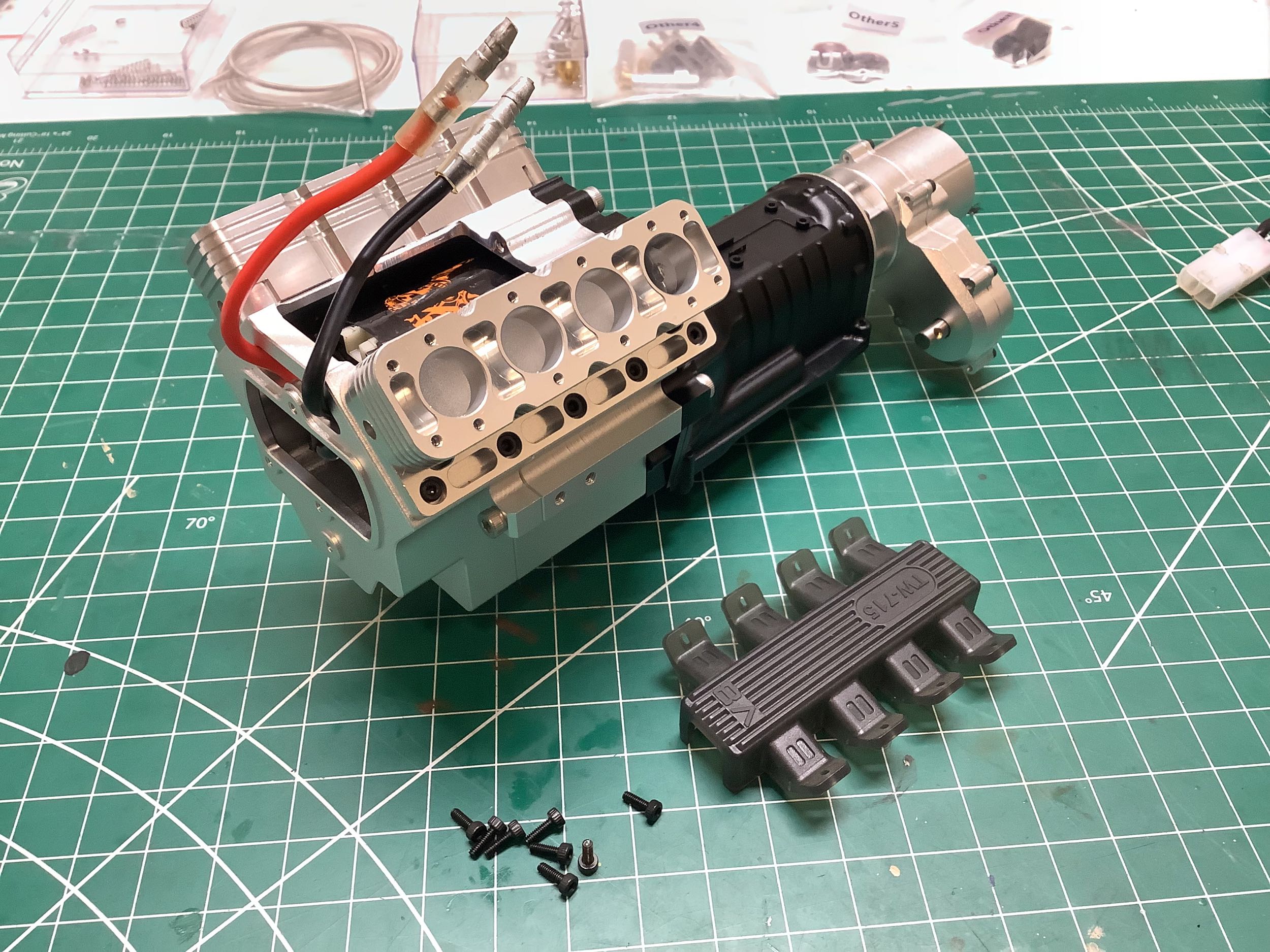
Here are some cool detailed engine parts. These cylinder bores sit
up on top where the heads should be. This is not strictly
accurate of course, but I appreciate the attempt at a scale
engine. There are even water jackets machined around the cylinder
bores. Nice touch!
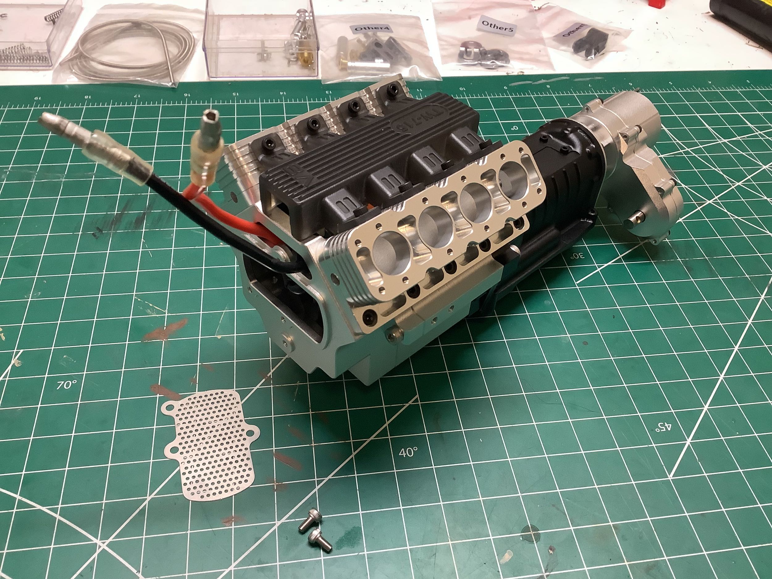
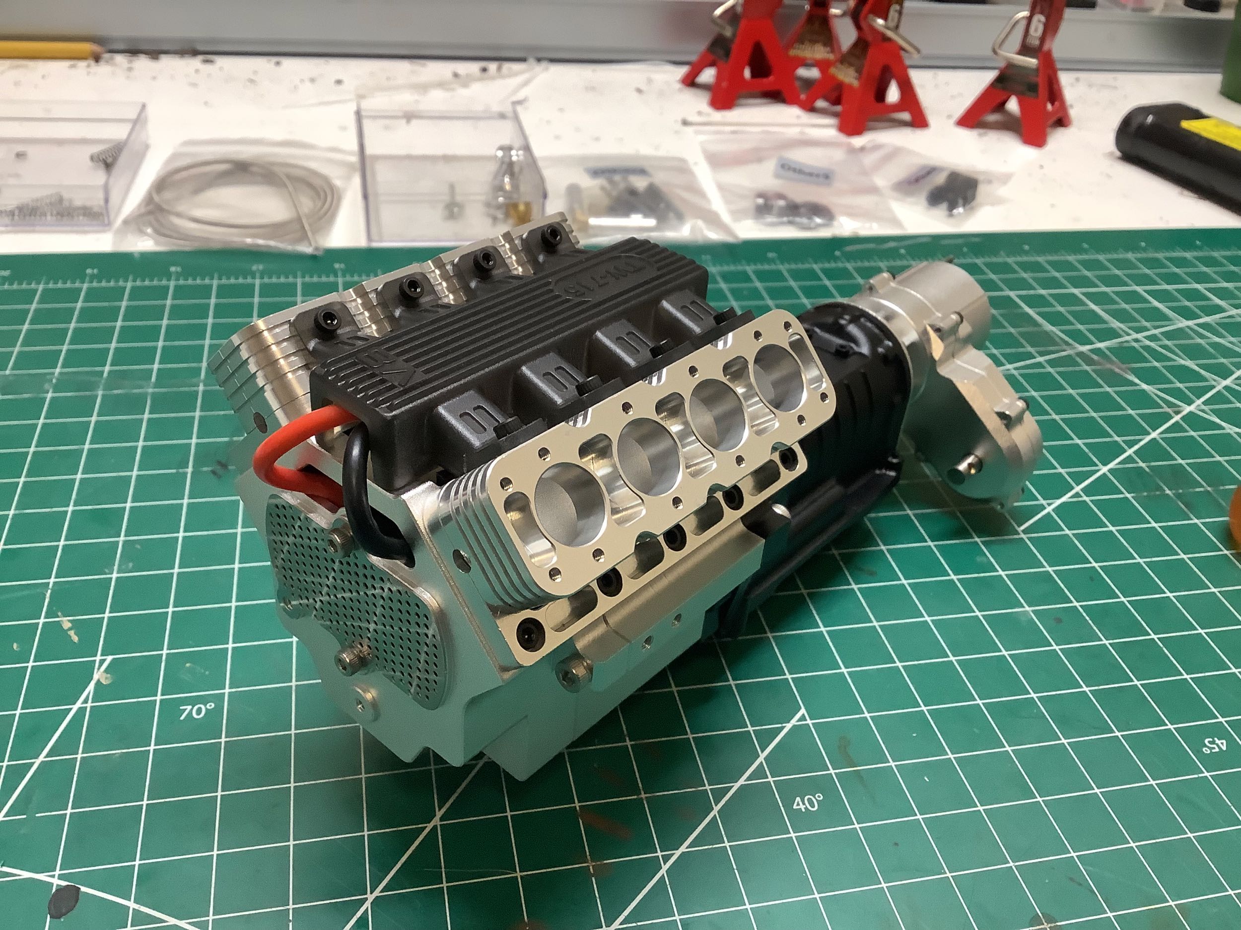
The final couple of details for the engine block are the intake manifold
and this photo etched part which bolts to the front. I don't
think it represents any particular part of a real engine (maybe a timing
cover), but it does allow some air flow into that enclosed interior to
help cool the motor.
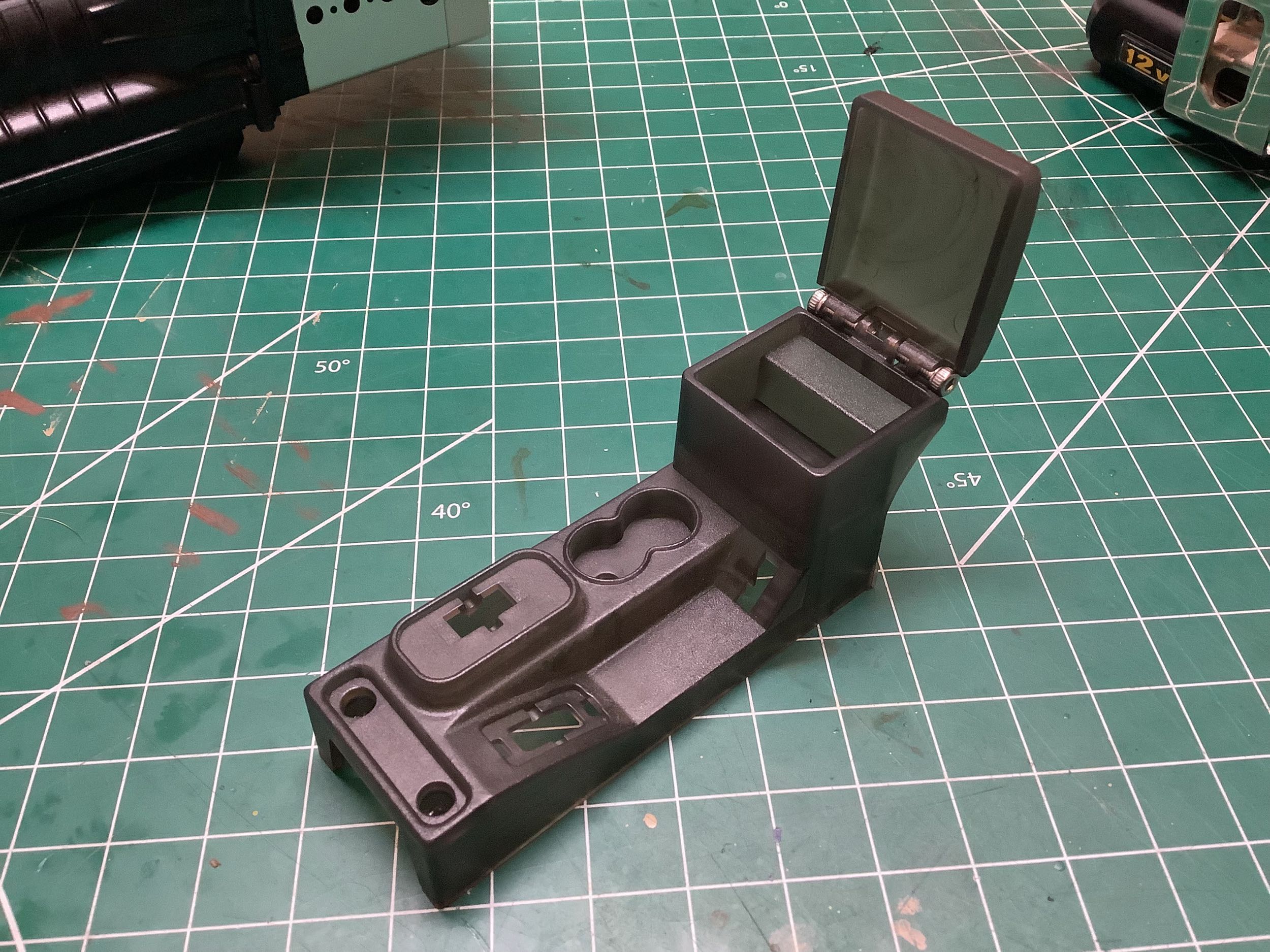
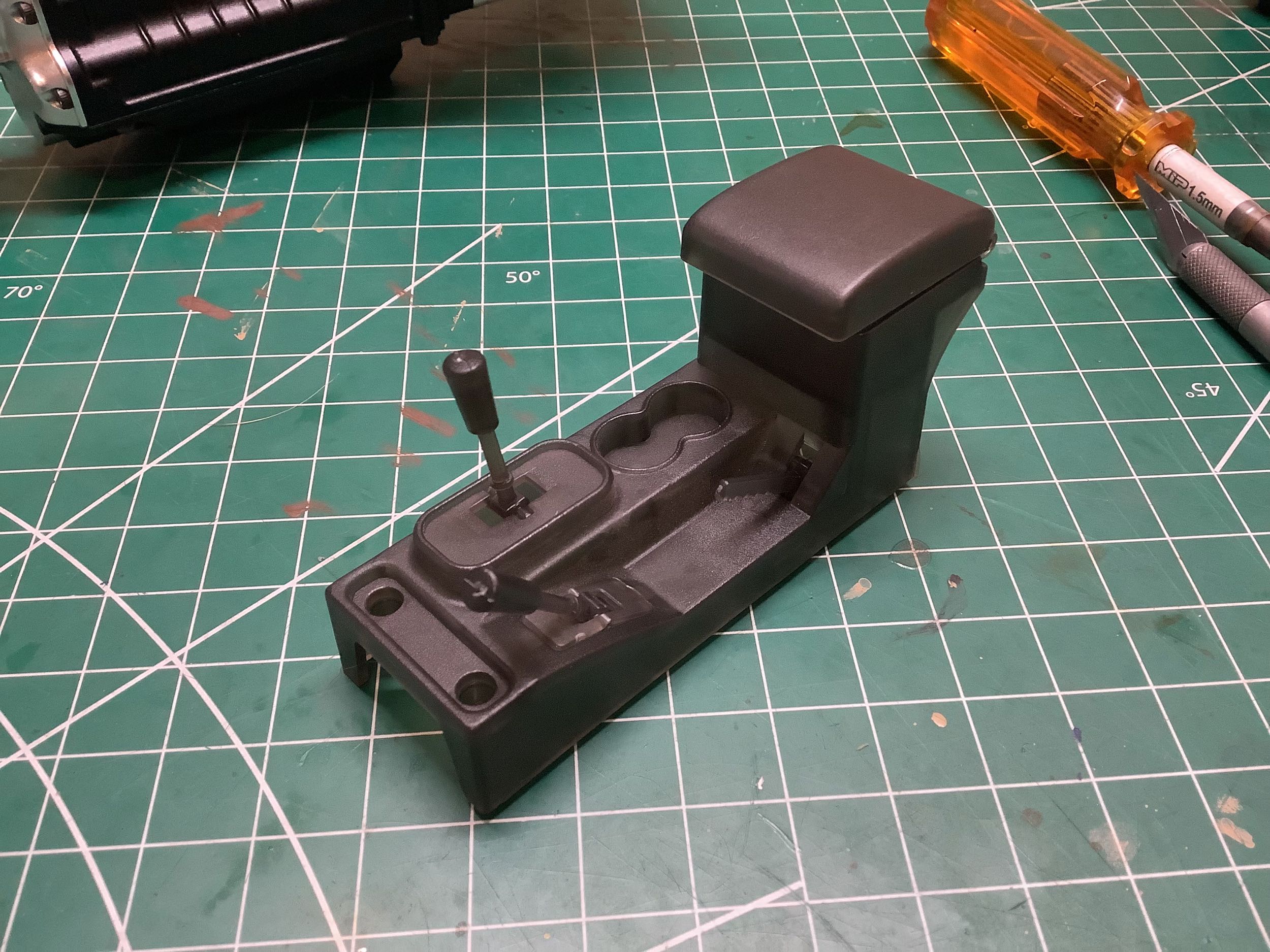
This might not look like part of the engine and transmission assembly,
but because of the way it mounts it appears in the same group of
steps. The center console is a single part with a separate opening
lid for the compartment. There are three levers here: a parking
brake lever, a shift lever, and a transfer case lever. The shift
lever will actually be linked to the transmission and indicate the gear
position. I'll be painting all of this later.
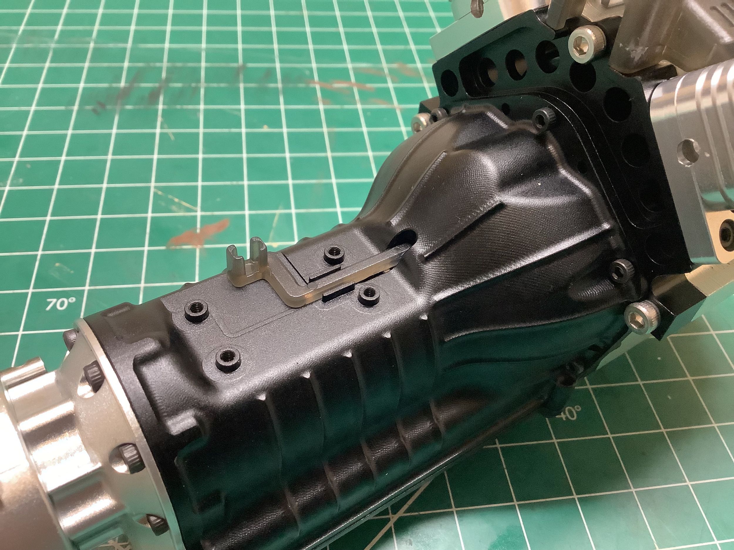
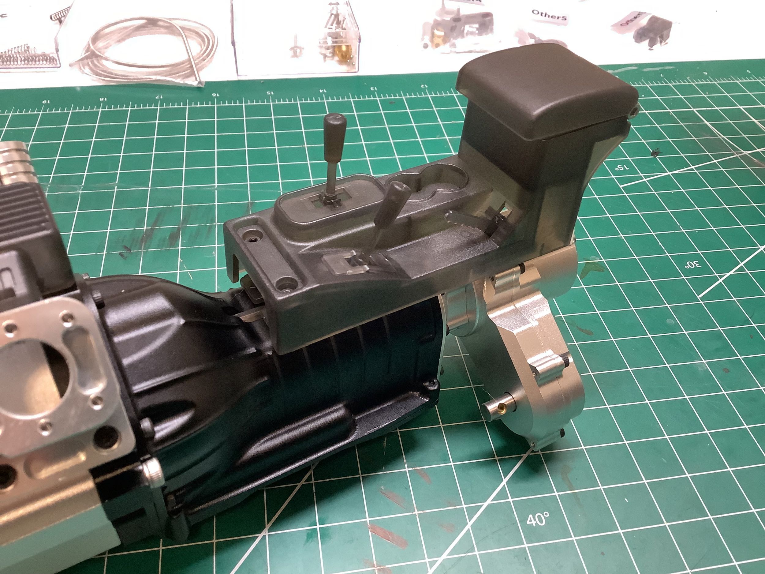
This little plastic lever (left) protrudes into the bell housing and
connects to the shift fork causing it to slide back and forth and
indicate the selected position. It connects to the lower shift
lever shown on the right. Unfortunately, the transmission refused
to shift once this section was installed. It turned out that the
sliding plastic lever was too thick and got pinched between the bell
housing and the center console, effectively locking out the shift
function. I had to sand down the lever to make it thinner and now
it works correctly.
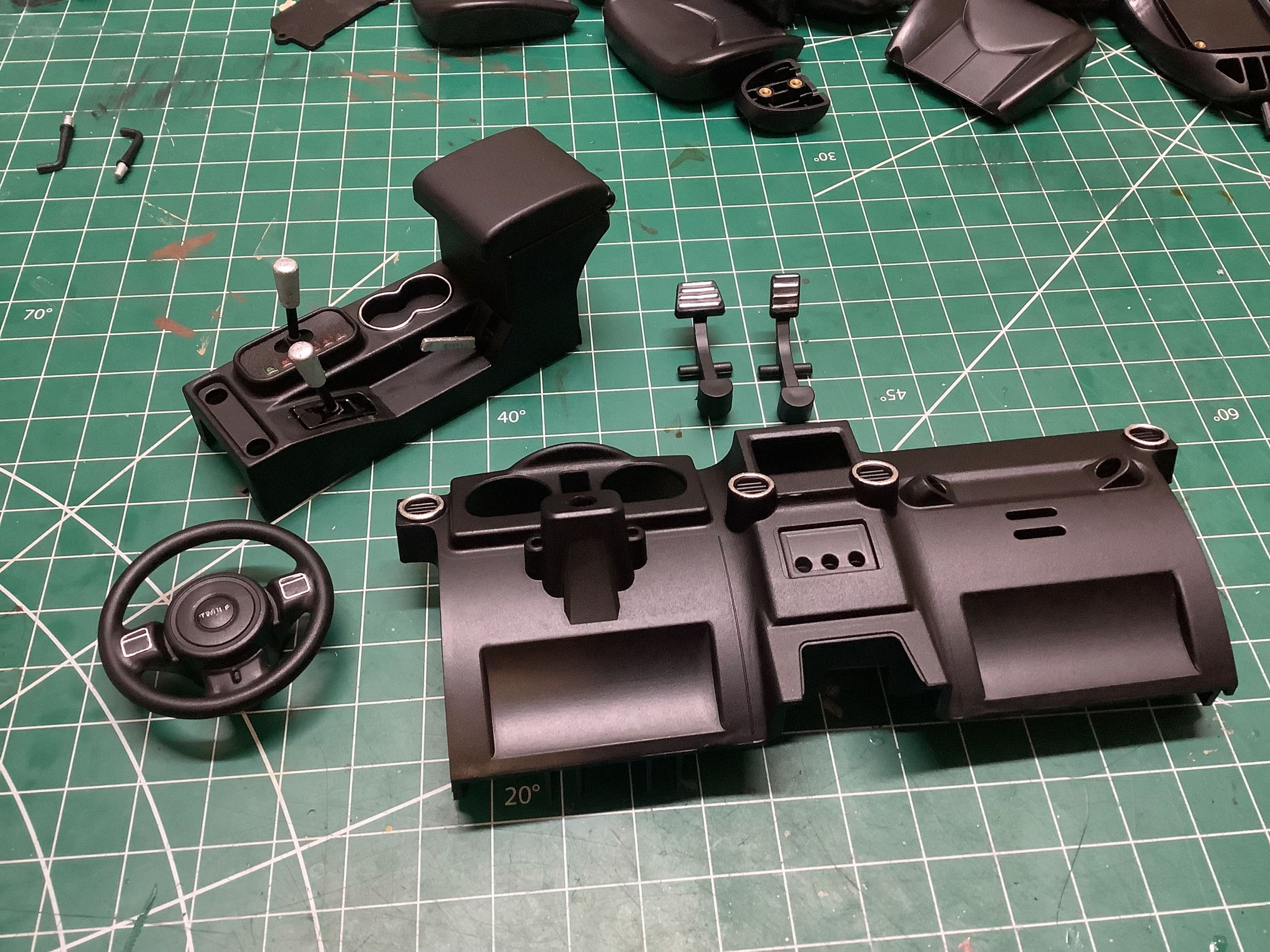
This photo was taken considerably later when I came back to do the
painting. The center console has been painted in semi-gloss black
and I've highlighted certain areas with a chrome paint pen. The
parking brake lever and gear selector can be moved even though they
don't attach to anything. The high/low selector functions as
described previously.
©2022 Eric Albrecht