TW-715 Project
Page 3: Building the Frame
The ladder frames of R/C scale trucks are usually made in one of two
ways: from formed aluminum C-channels, or from flat aluminum bars.
This frame is very different. Every portion of it is machined
from billet and pocketed for weight. There are multiple changes in
frame width and height meaning that these are not just simple flat
bars. This frame was a true joy to put together and represents a
real piece of fabricated art. Each of the parts is connected with
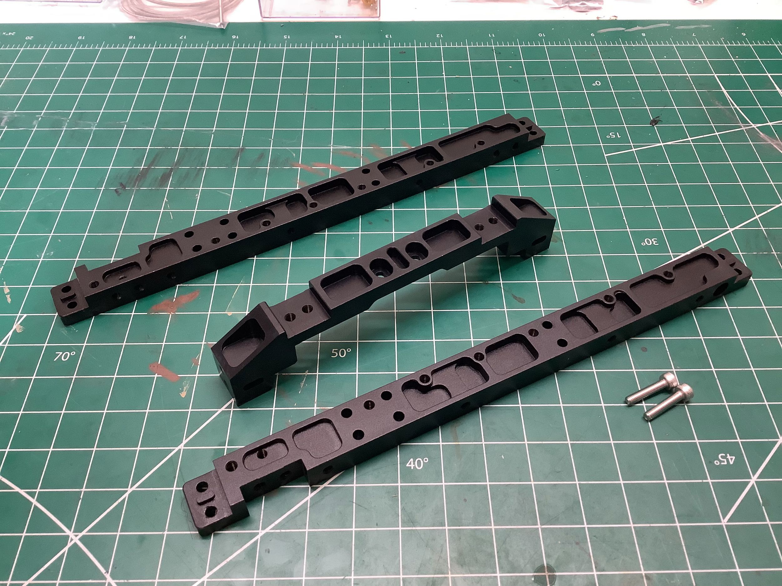
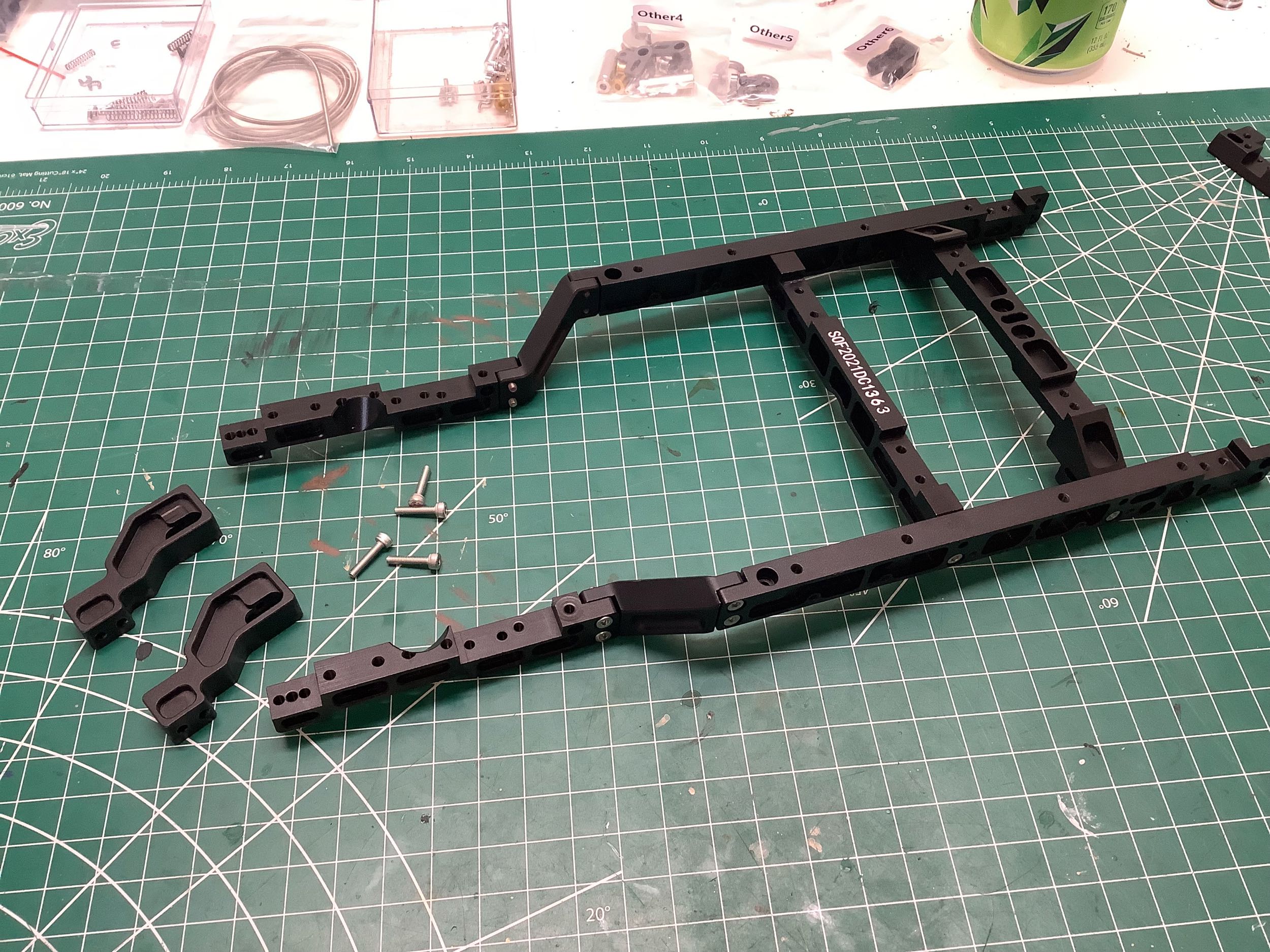
at least two screws to prevent rotation. The build begins with a
pair of rails that form the central portion of the frame fastened
together with a complex machined cross member as shown. I was
careful to use thread lock on all these screws.
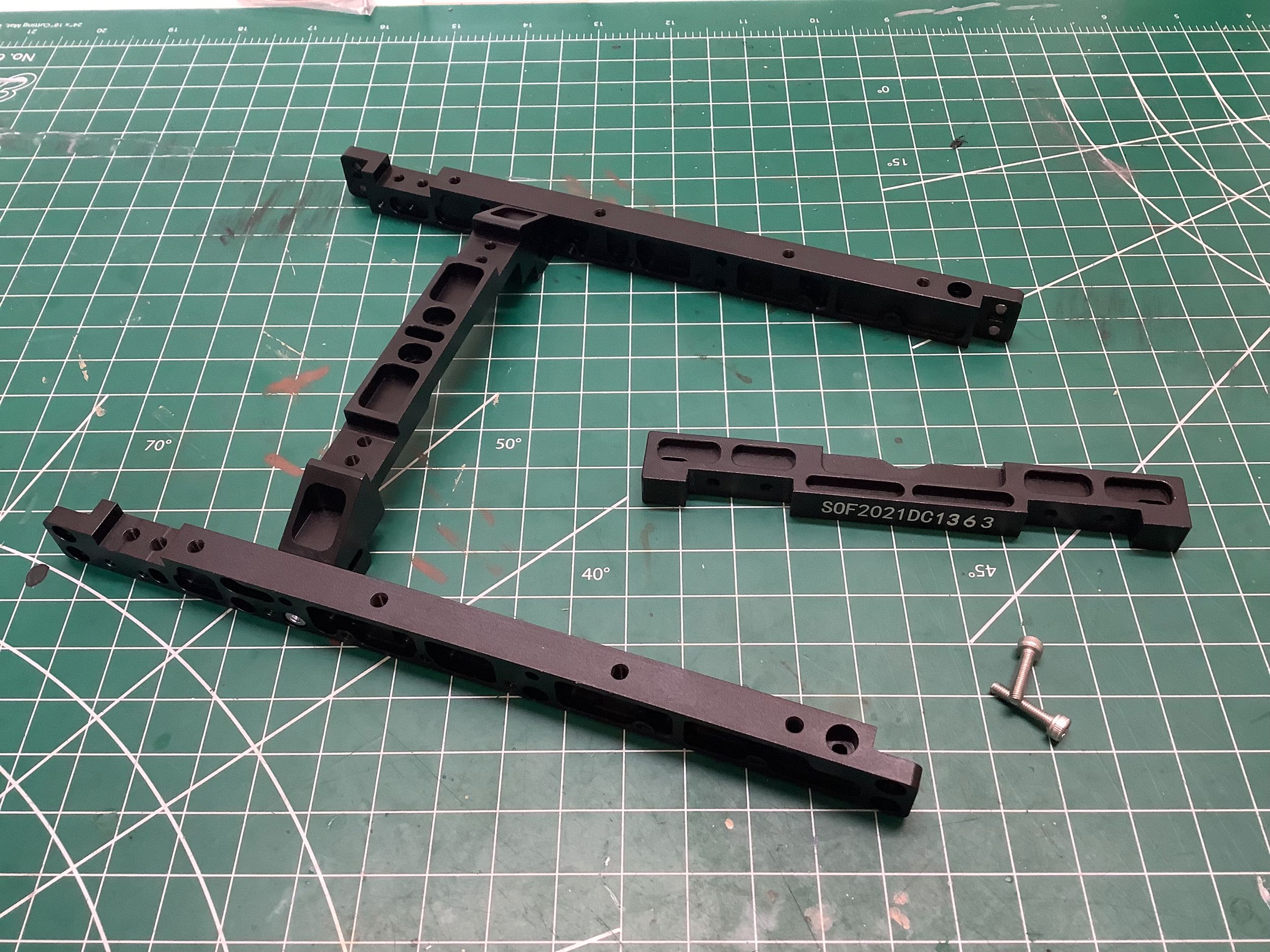
You can see some text printed on one of the cross members in the image
on the left. I'm not sure if this is just the model designation or
if this represents a unique serial number for my copy. The latter
seems possible. At this point the frame is being built upside
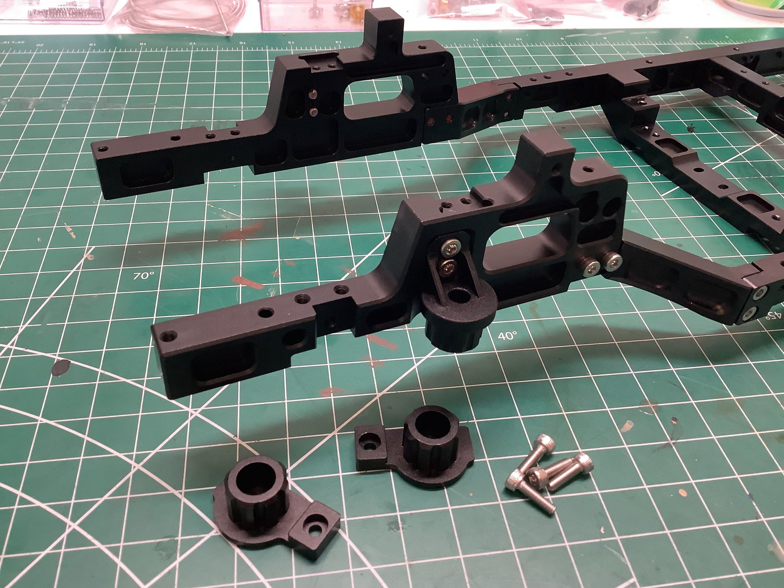
down so those angled parts actually pinch in and up moving towards the
rear. Take a look at the angled cylindrical pockets shown in the
new parts on the right. These are to clear the rear shock
absorbers. A close look at the details will also show that each
part of the frame is physically keyed to the next. These are not
just plain lap joints; each piece has a feature to lock it to the next
in a specific orientation. That's good engineering.
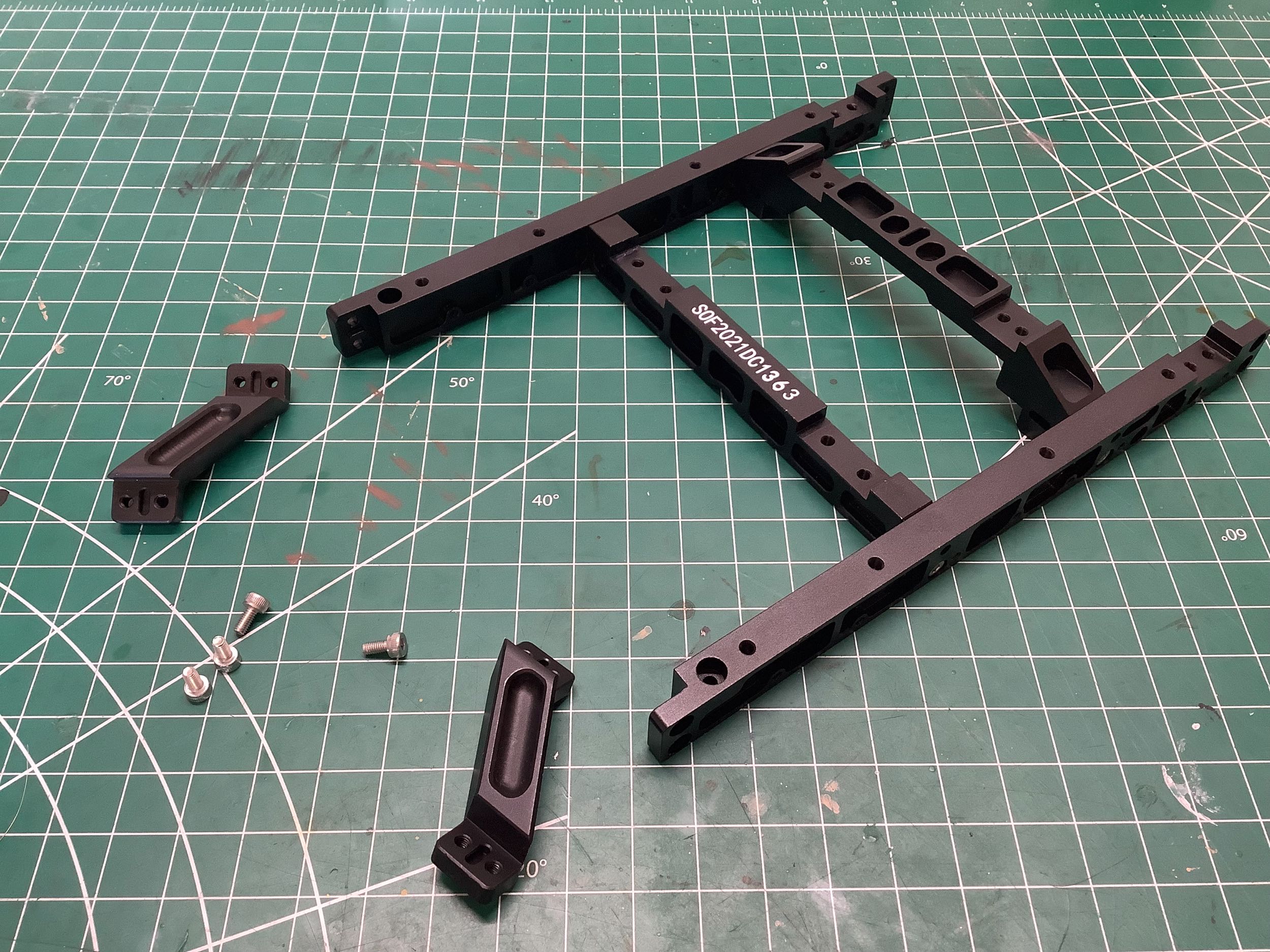
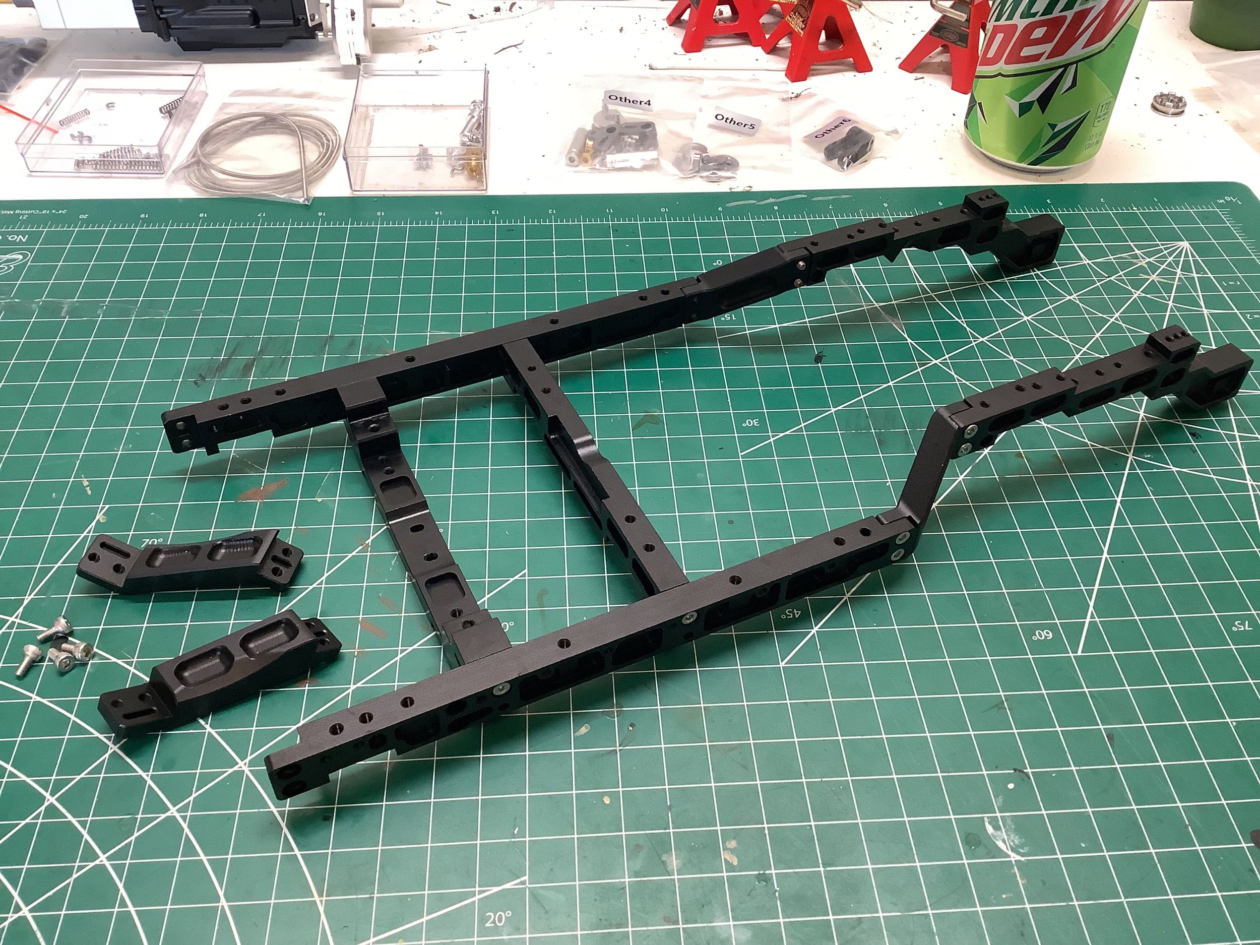
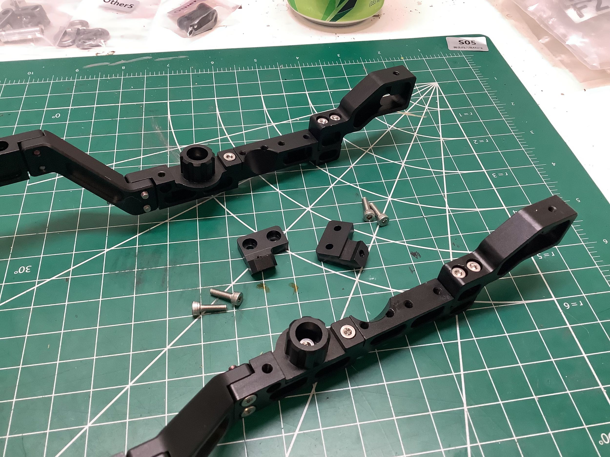
We've almost completed the back of the frame. These final two
parts (left) will eventually support the rear bumper. On the right
the frame has been flipped over and we are now working our way toward
the front, again with a pair of sections which pinch up and
forward. The frame is getting pretty big at this point to only be
connected with two cross members in the middle.
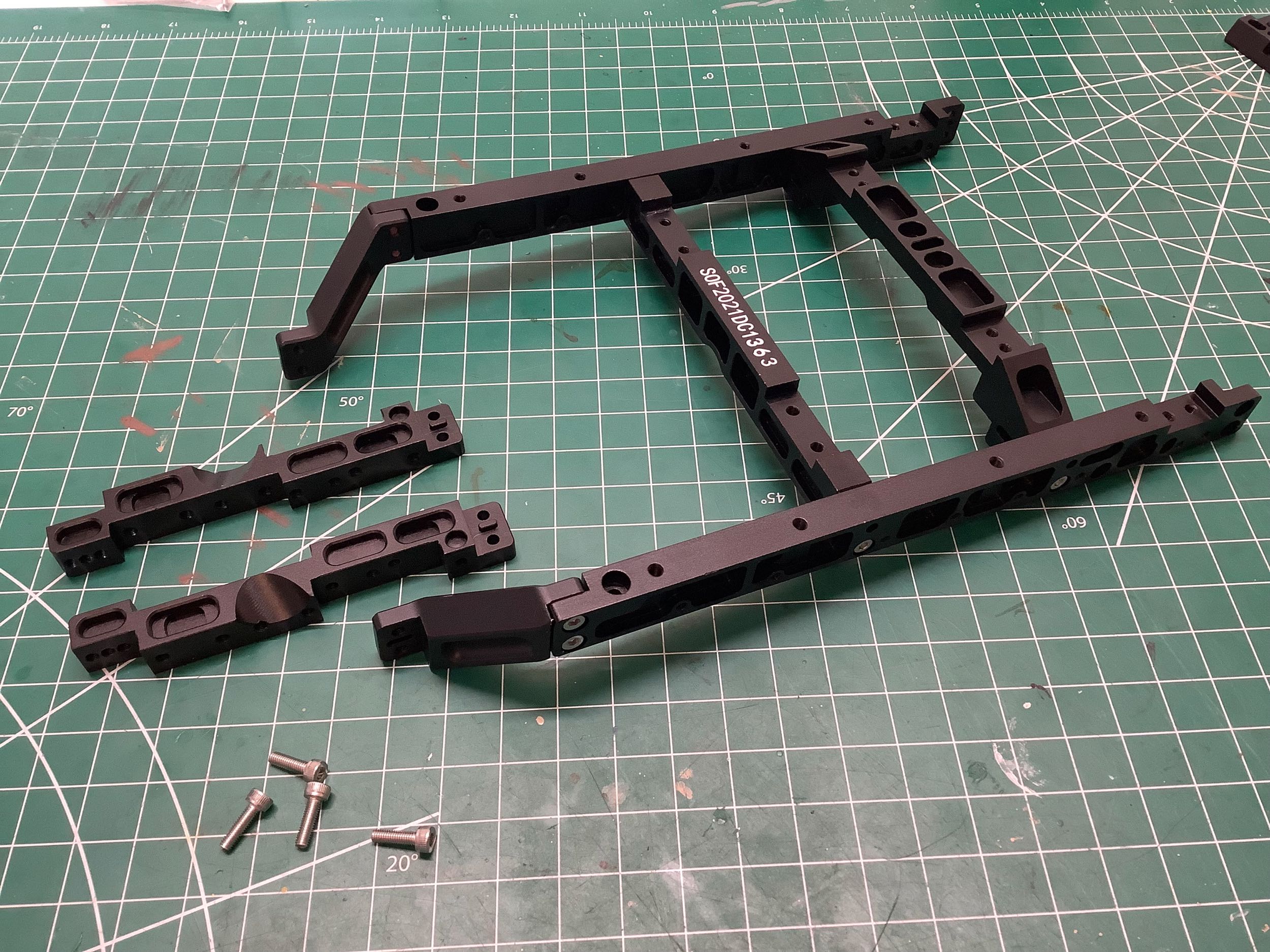
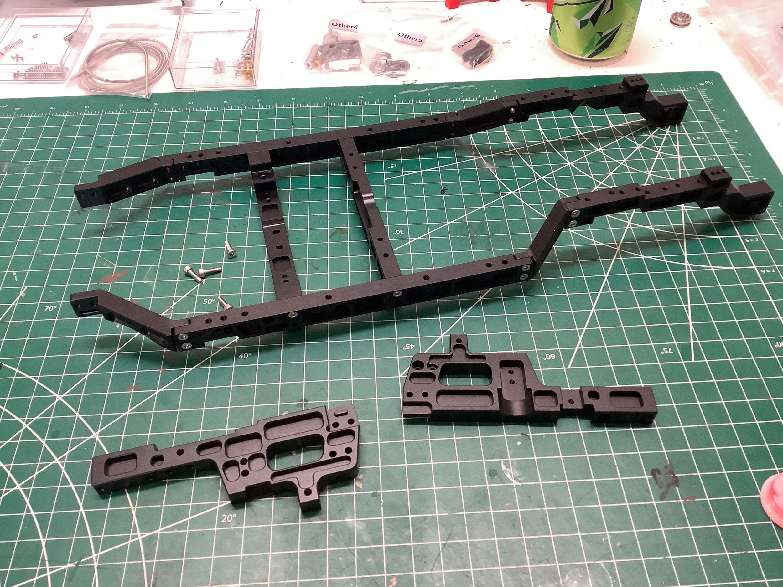
Now we'll add the two most complex parts of the frame. These bits
act as the front shock hoops and will also support the motor mounts and
front bumper. This completes the basic frame with a total of 14
complex machined parts, but we're not done yet. We also need to
provision the frame for the coil springs. The cylinders shown on
the right will form the upper support of the front springs.
The picture on the left shows a close-up of the upper front spring
supports with the parts that will be attached similarly at the rear
(attached at right). The final brackets shown at the right are for
the rear shock attachment.
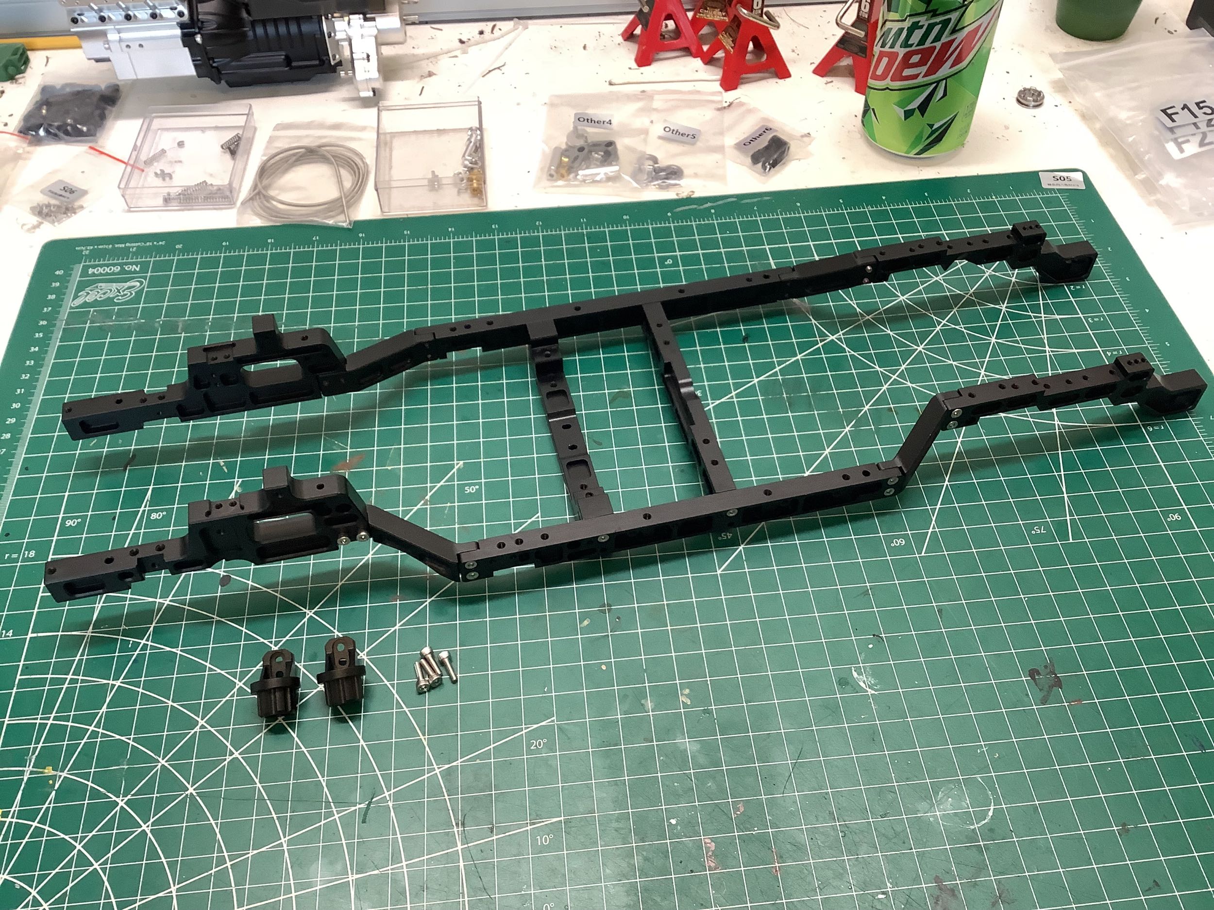
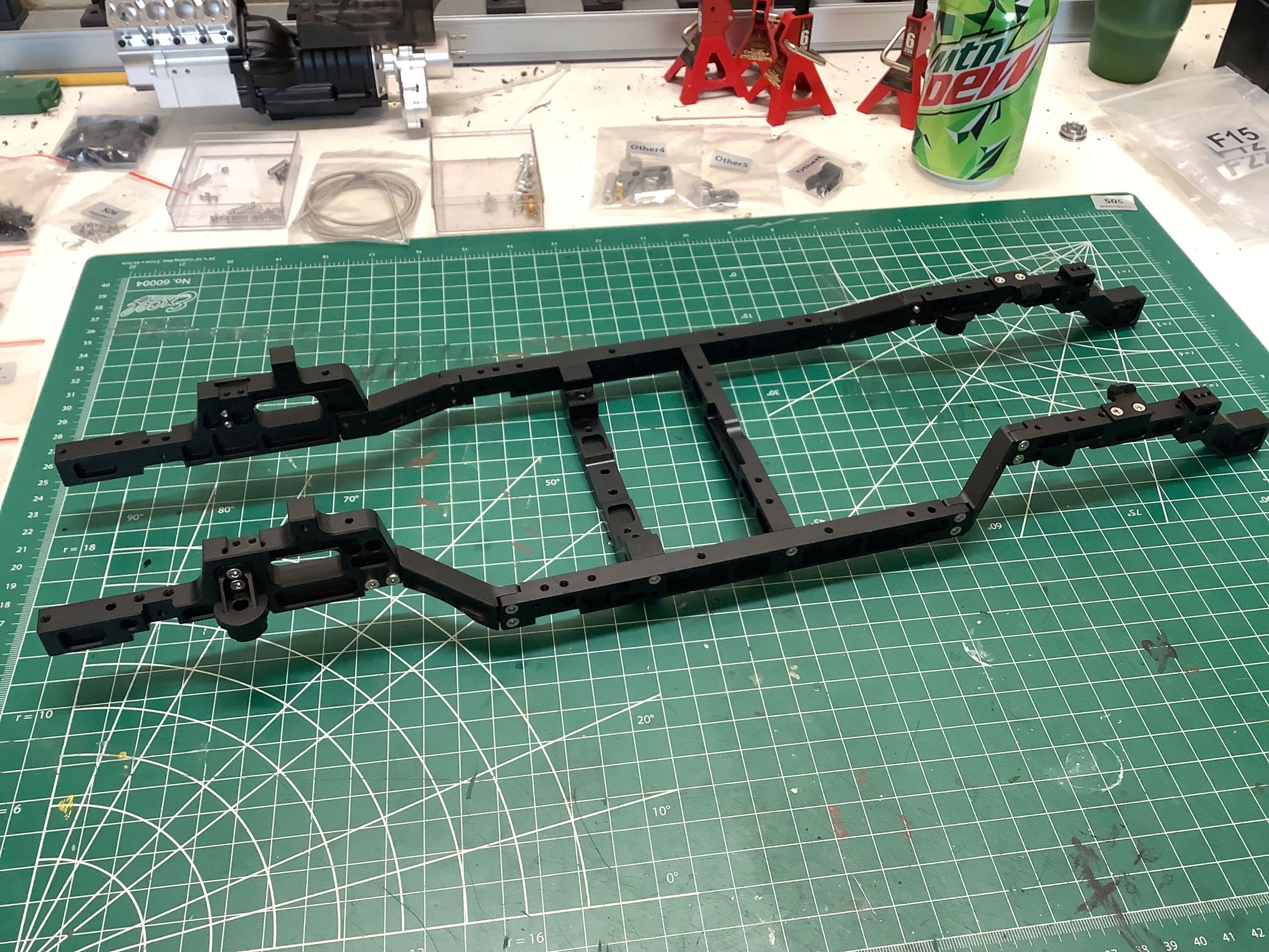
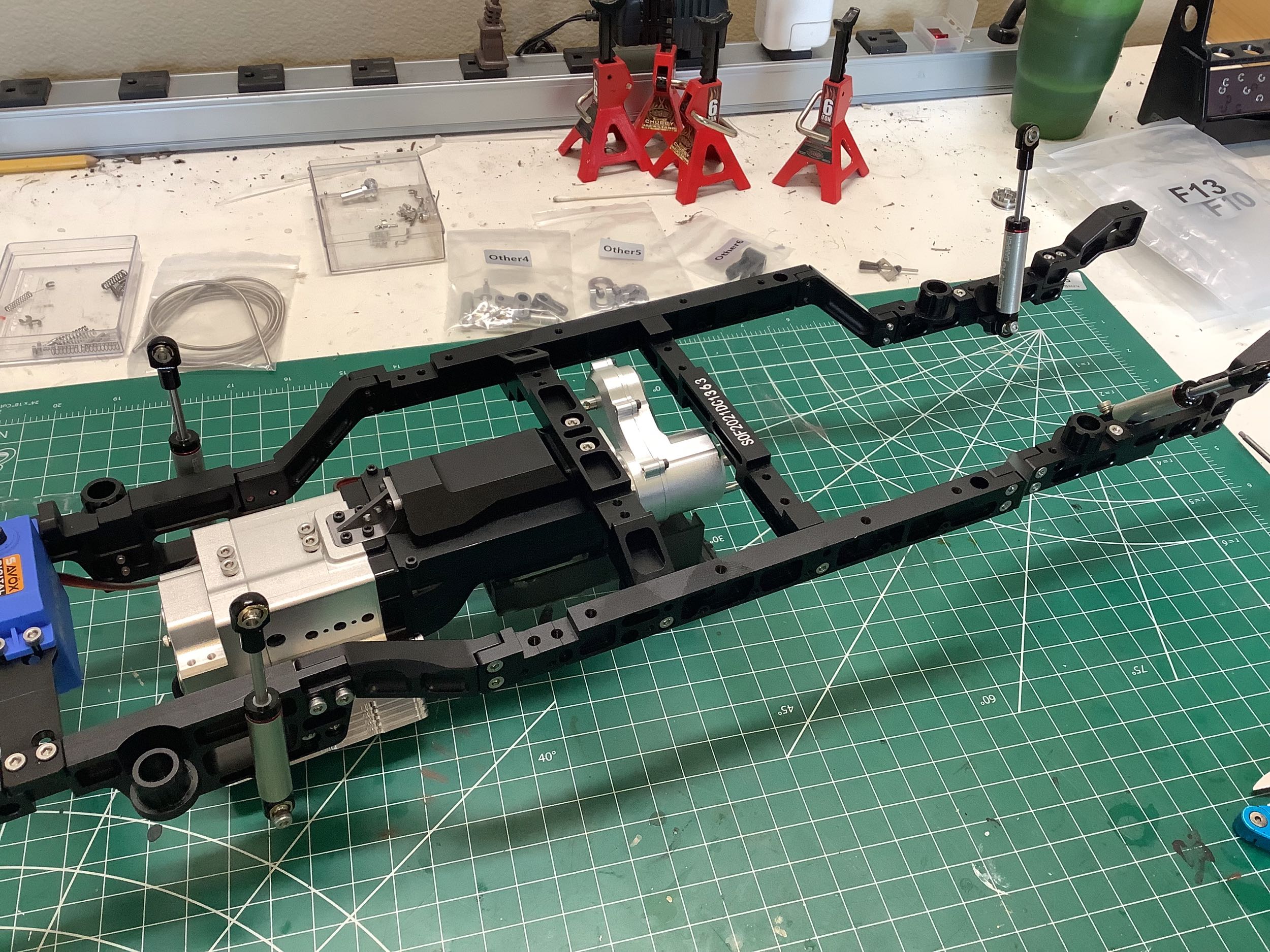
Here is the fully completed ladder frame. Despite the enormous
size (each square is one centimeter) and all metal construction, it is
actually very light.
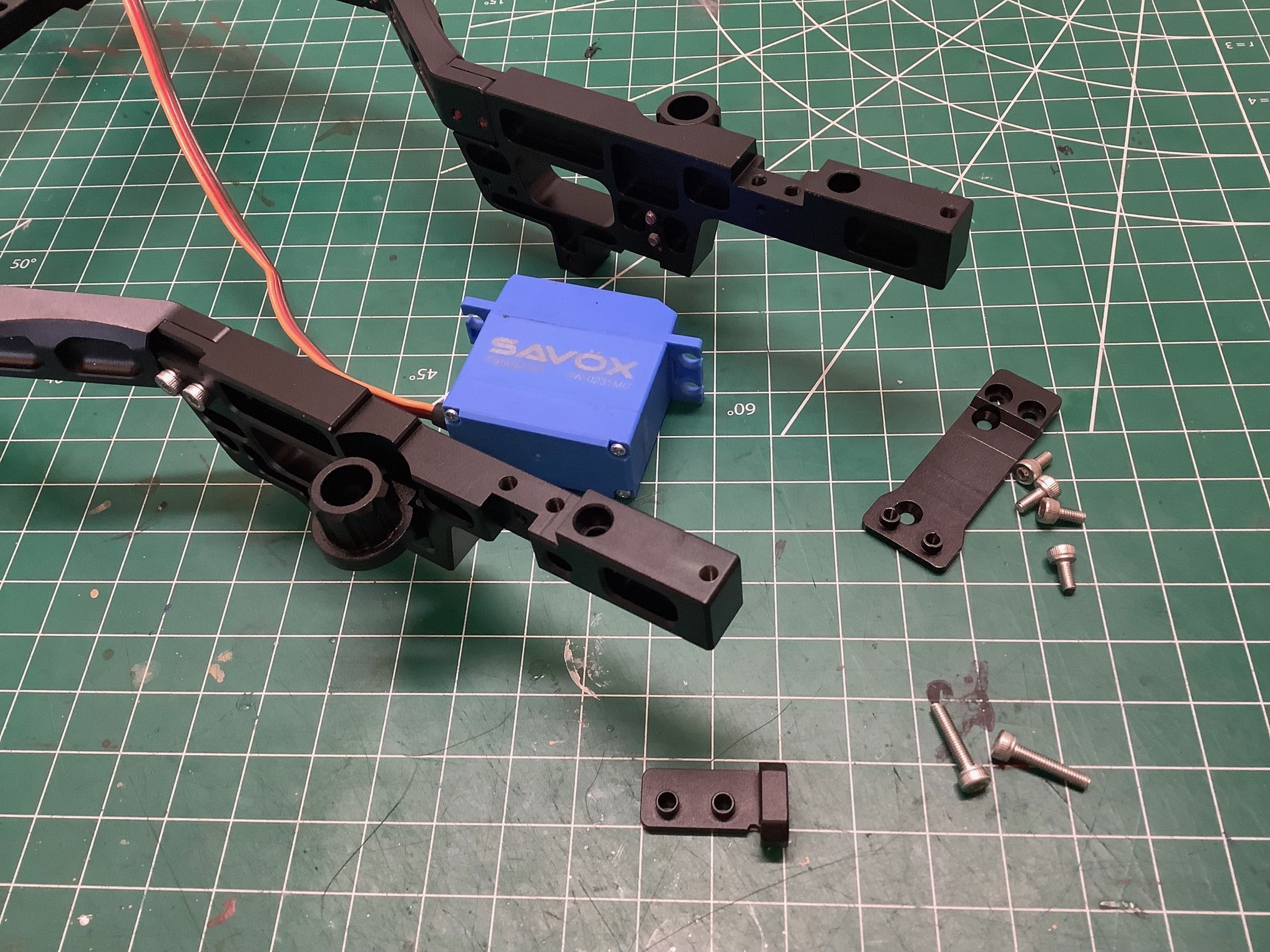
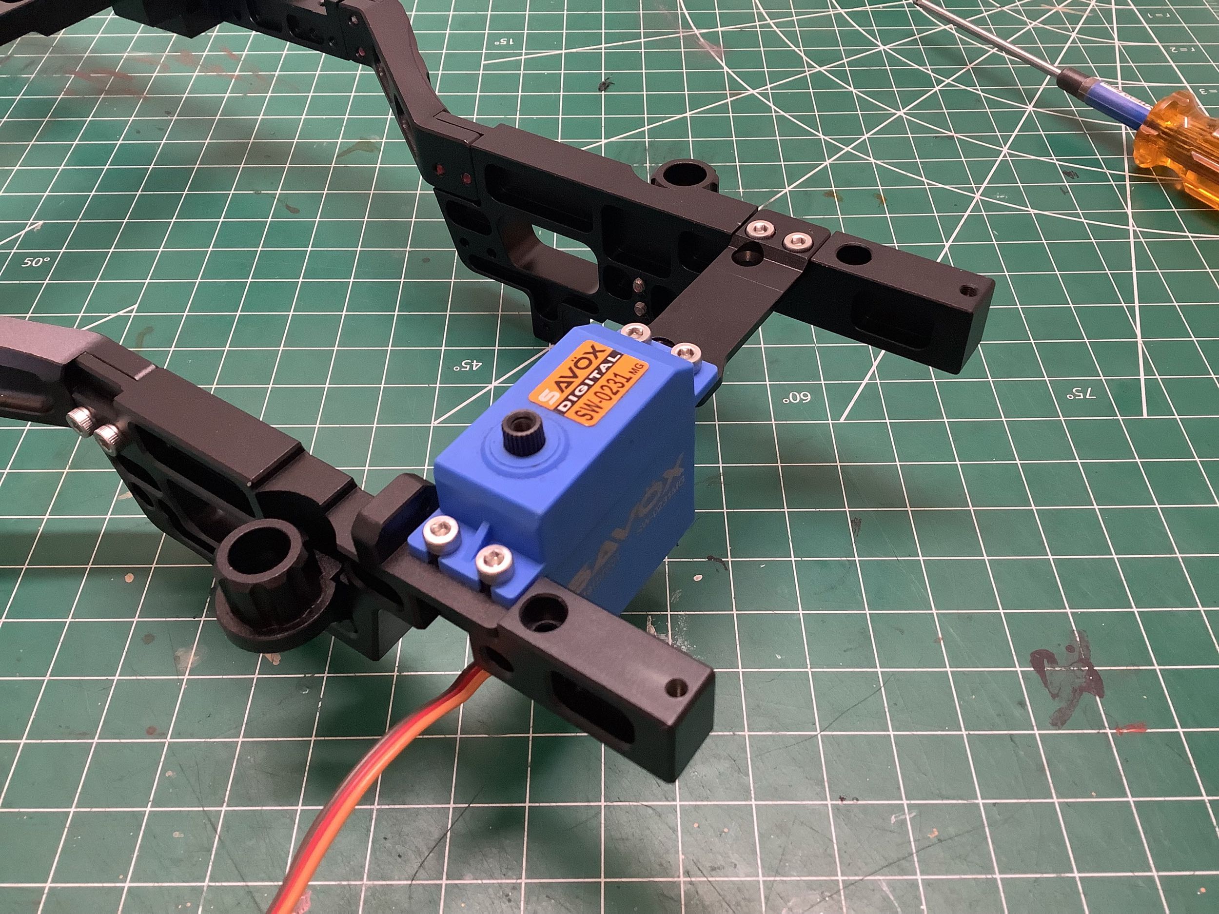
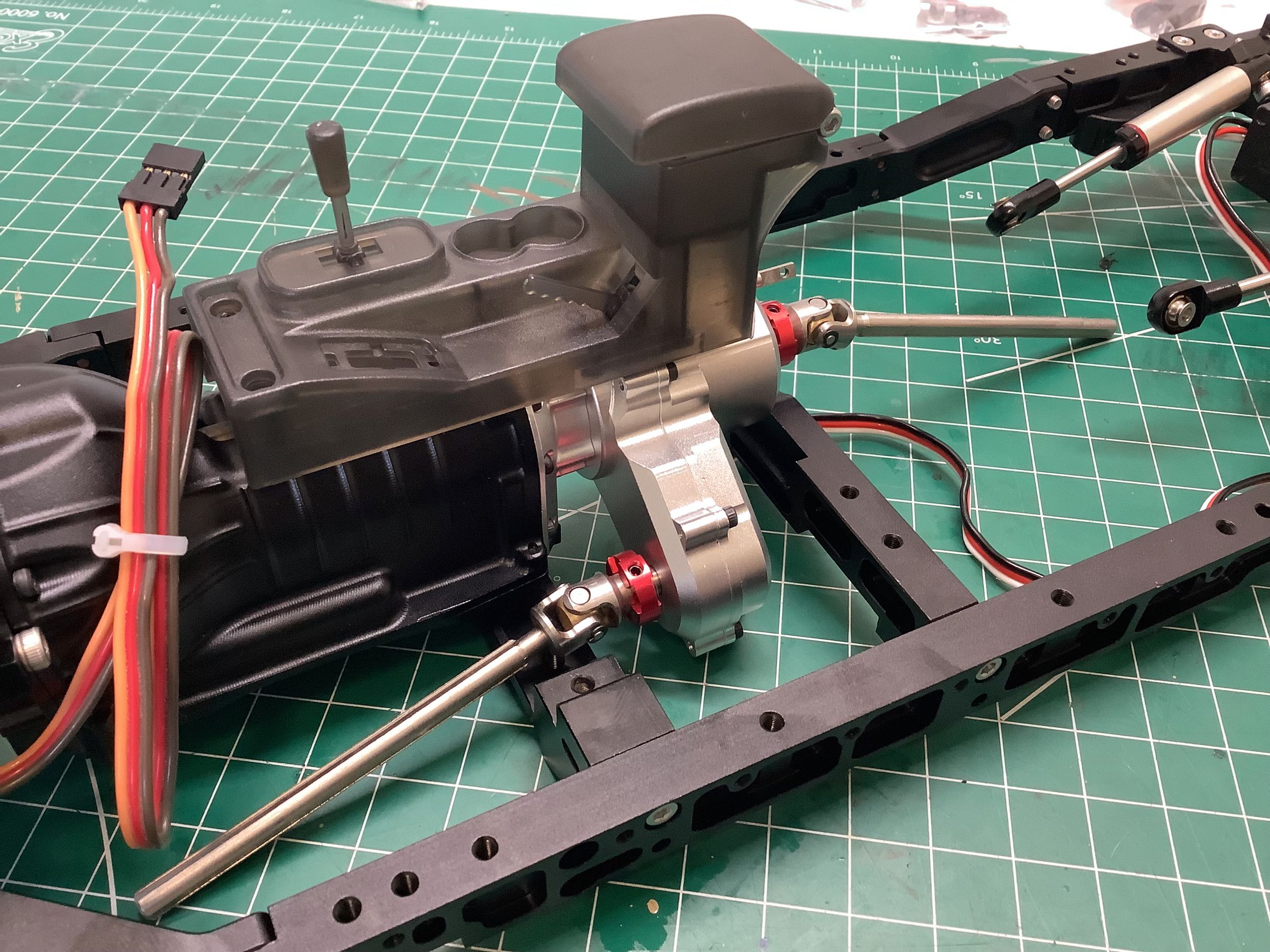
I intended to use a top end Pro-tek Black Label steering servo for this
model, but I didn't have it yet so I installed this Savox servo
instead. The servo is chassis mounted and actually forms a
structural part of the forward cross member of the frame.
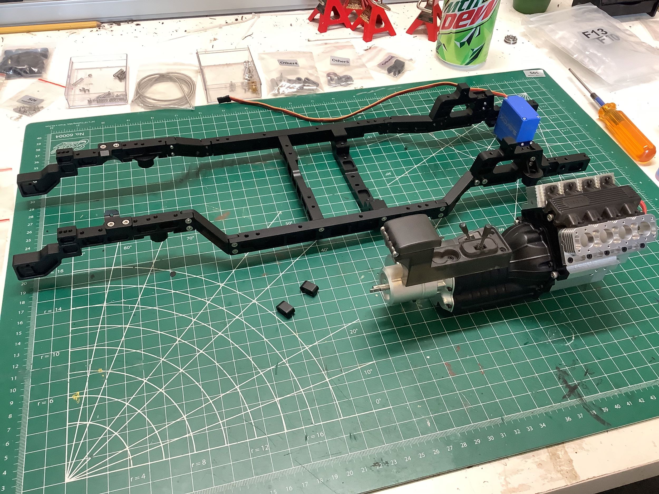
Now the engine and transmission assembly can be installed. There
are two screws on either side of the block that pass through the spacers
shown on the left, and two more screws that connect the transmission to
the forward cross member. Installed in this way, the engine
assembly noticeably stiffens the frame. Note now far back it is
installed. The front of the engine is even with the front wheel
arch.
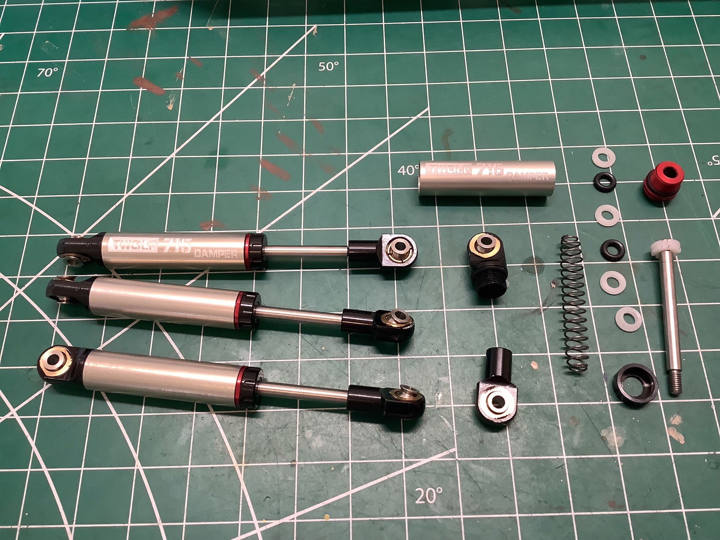
The full metal shock absorbers were already assembled in the package,
but I had to tear one down just to see what was inside. You can
see the result on the left. The shocks are internally sprung, but
these little springs don't hold up the model, they just handle shock
rebound. I saw o-rings so I figured I could try filling these with
some light oil. Because there is no volume compensation, you
can't put in very much oil or you get a hydraulic lock. I needn't
have bothered. The oil leaked out almost immediately. The
diameter of these shocks is quite small for an R/C truck, but I'm OK
with that because they are way closer to scale than the monsters you see
on most models. On the right you can see the shocks installed to
the frame.
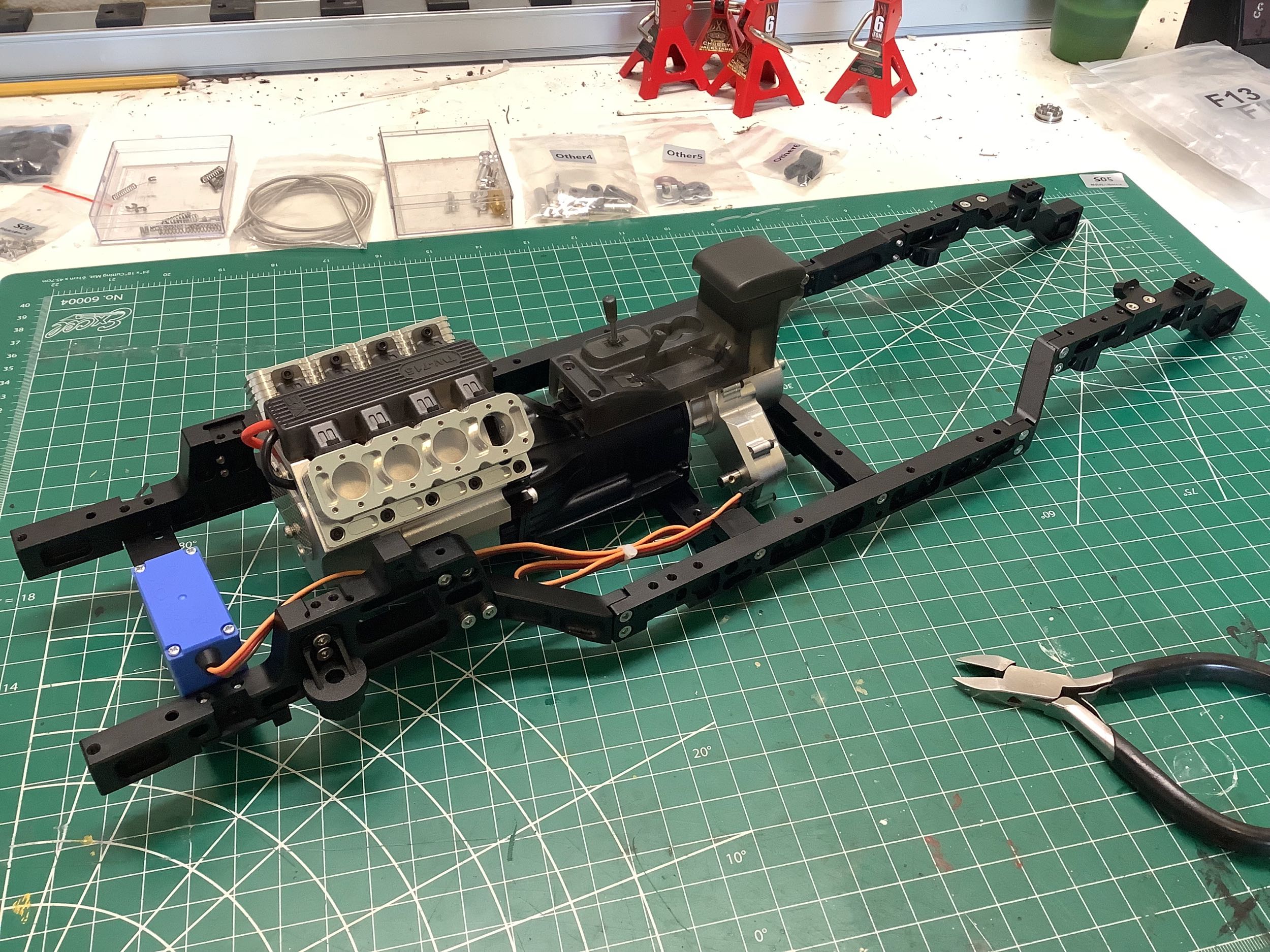
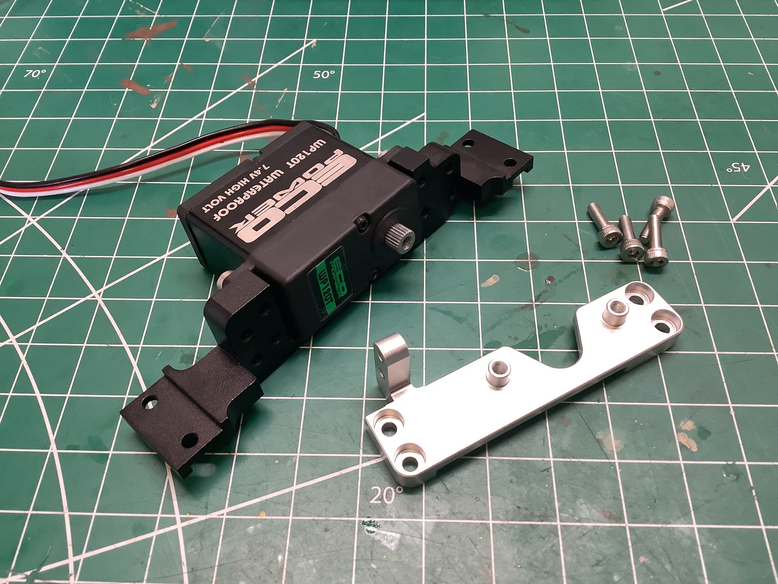
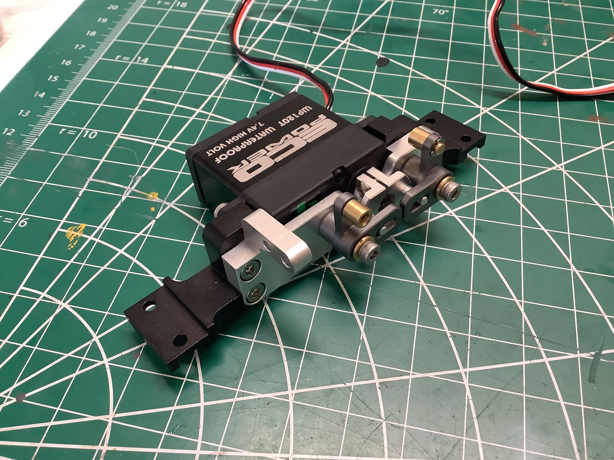
The rear cross member is a bracket that houses another servo for locking
the differentials. The manual recommended a high torque servo
here so I used an ECO Power 120T with all metal gears. The
aluminum bracket attached next will hold the mechanism for installing
the diff lock cable system. That part on the right is the servo
horn which thankfully had 25 teeth on the spline to match my
servo. Sorry KO Propo users.
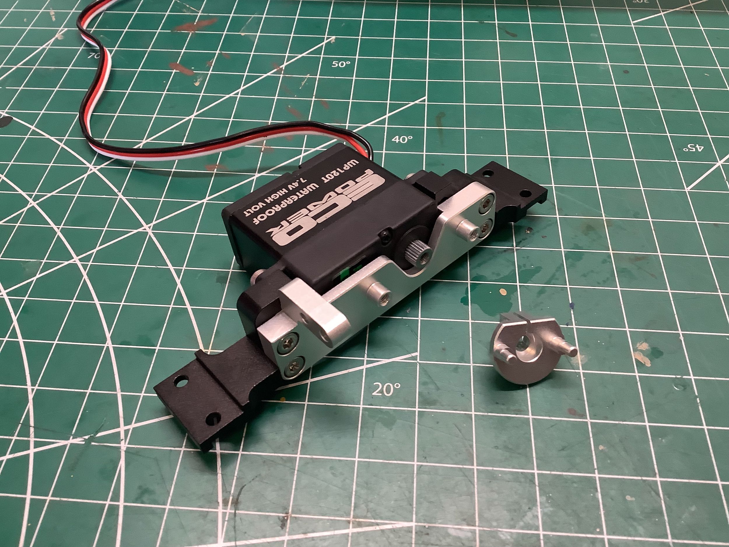
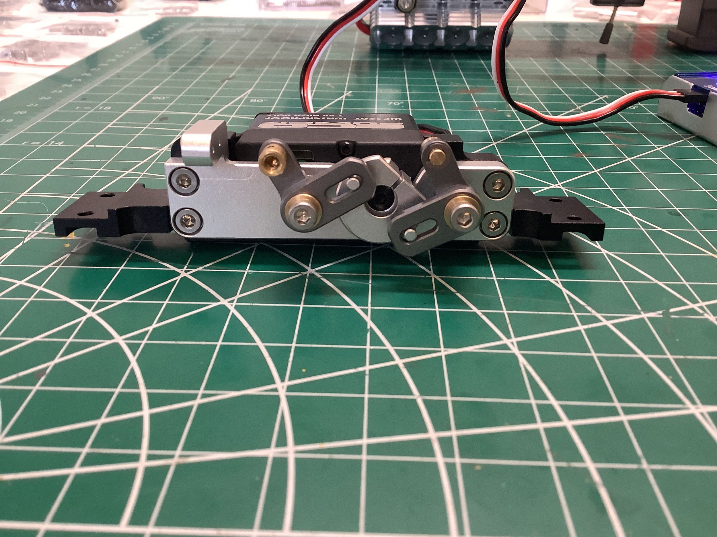
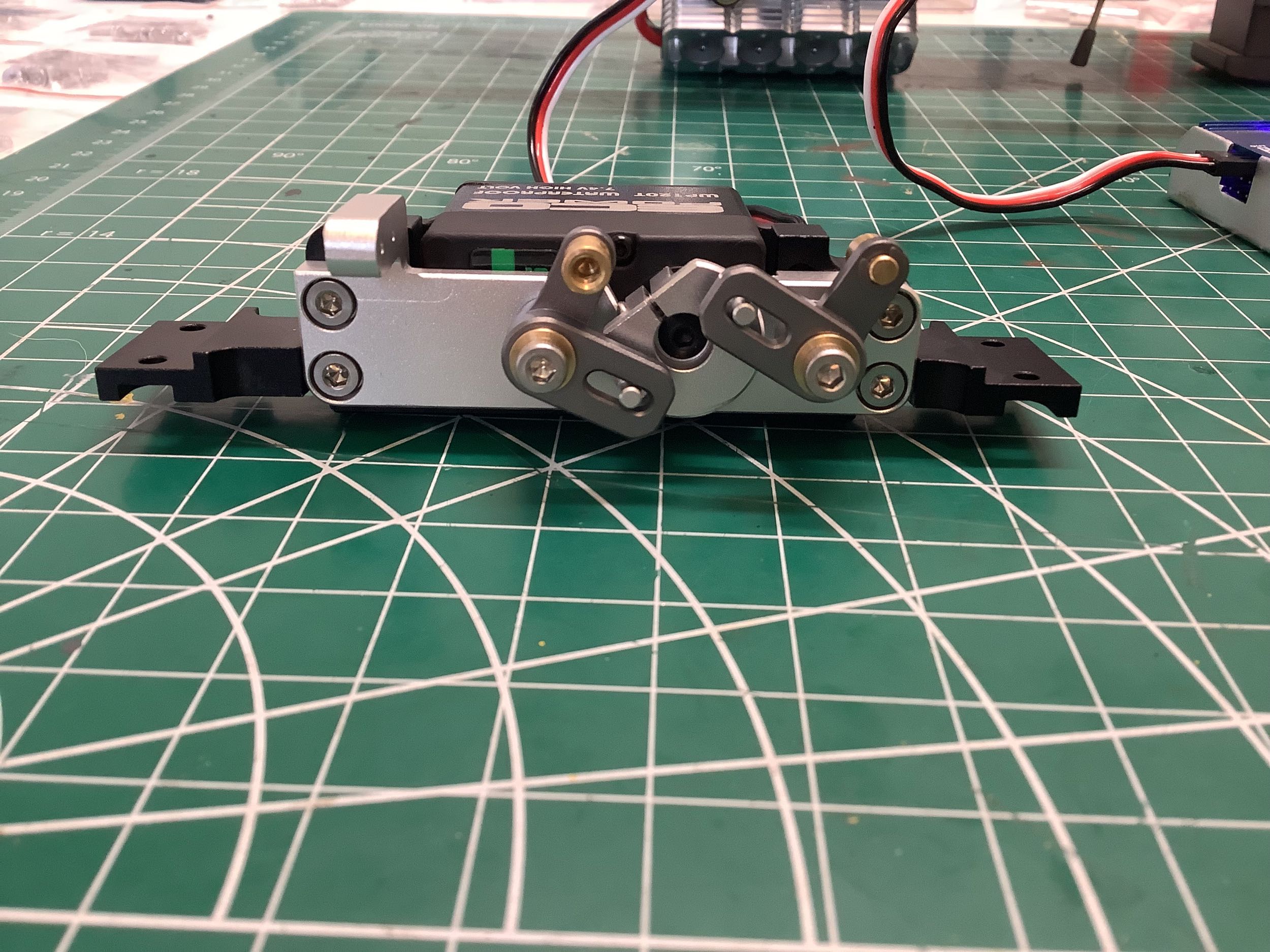
These aluminum crank arms pivot on standoffs on the brackets. The
slots mate with standoffs on the servo horn. At the other end of
each crank is a cable clamp. This will all make more sense later
when I have the cables installed.
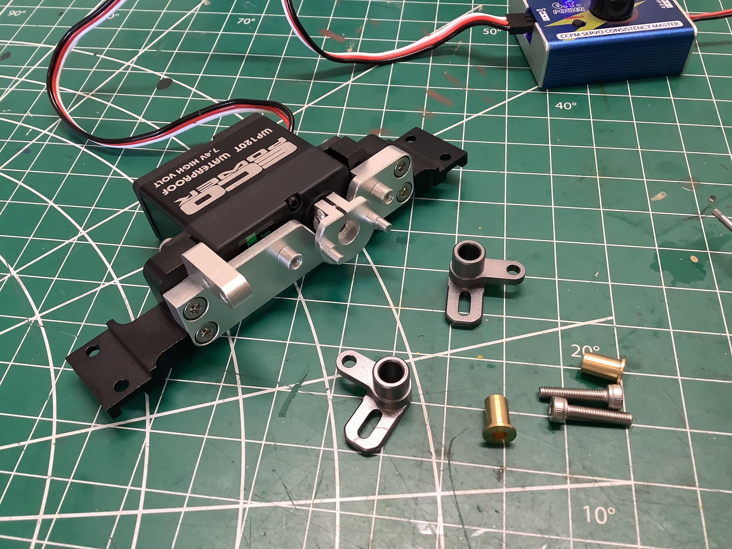
These photos show the extreme travel positions of the diff lock servo:
-100% to +100%. You can see the lateral displacement that will
result at the cable ends. The movement is not entirely linear, but
close enough for all practical purposes.
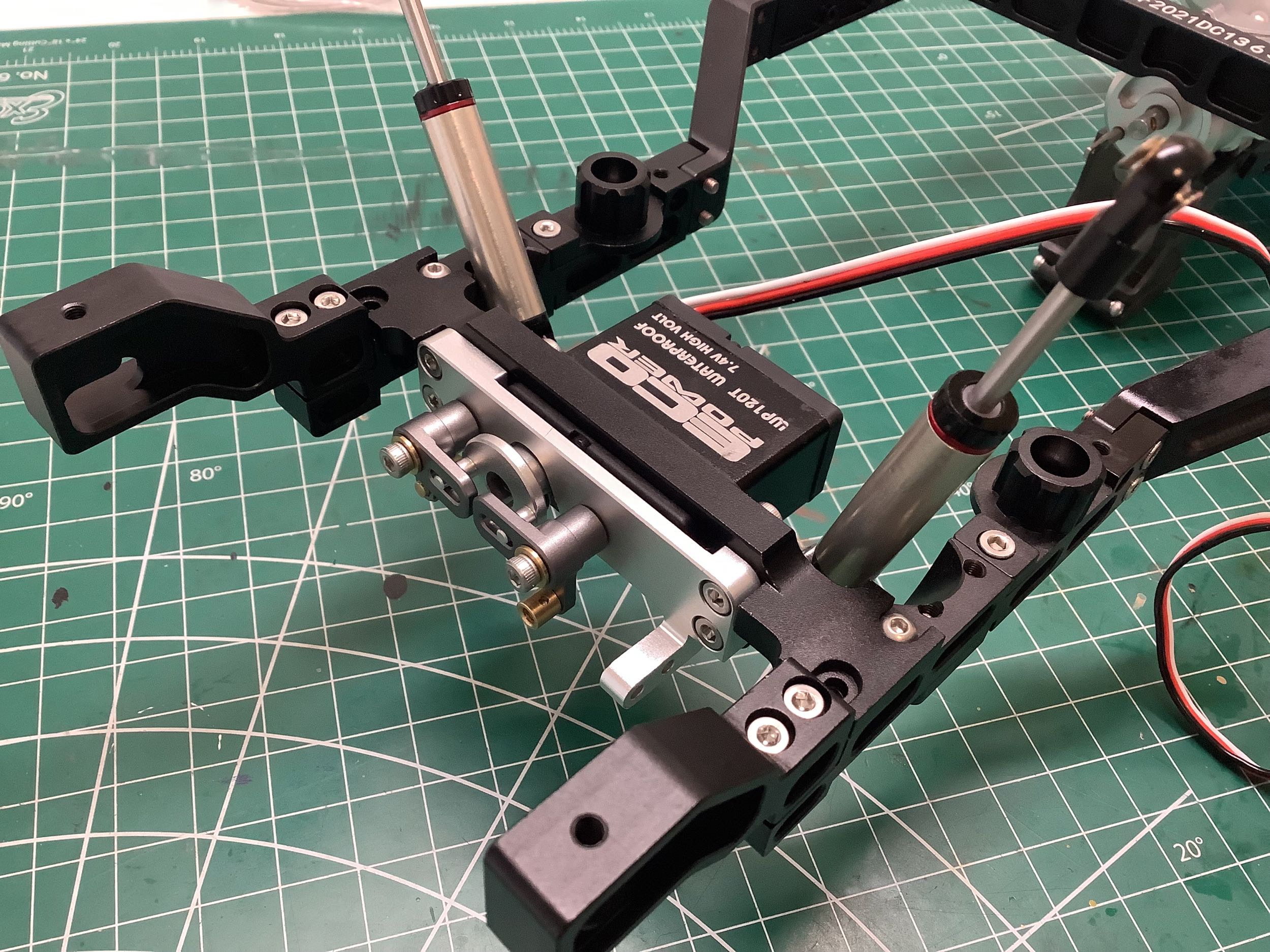
Here the diff lock servo assembly has been installed on the rear of the
chassis. I didn't realize until much later that I'd actually
installed it wrong. It should be sitting on top of the frame
rails, not beneath them.
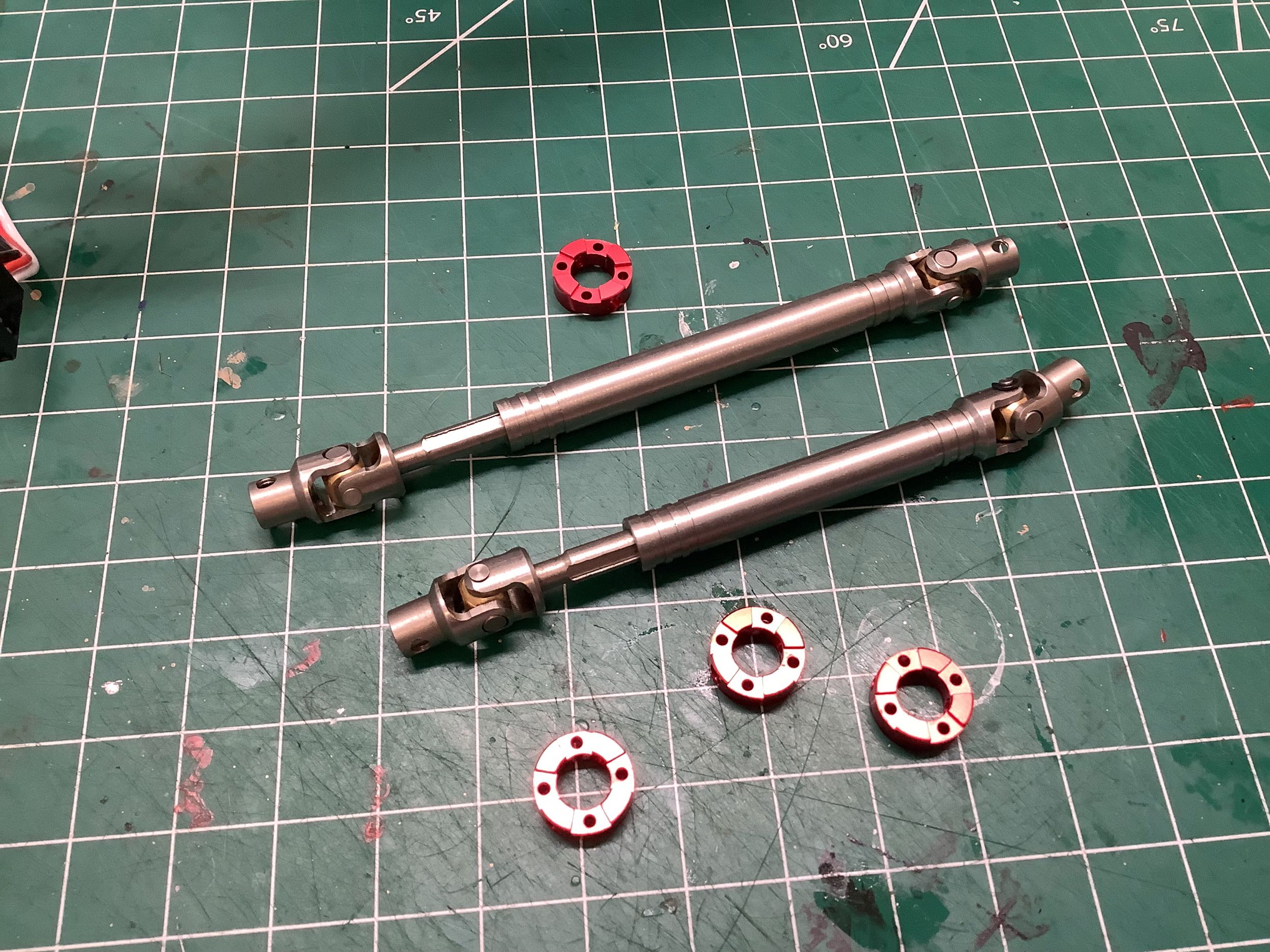
The telescoping drive shafts are solid metal. They are not
magnetic and, from that and the color, I suspect they may be
titanium. On the right the front and rear drive shaft halves have
been attached to the transfer case.
©2022 Eric Albrecht