TW-715 Project
Page 8: Upgrades!
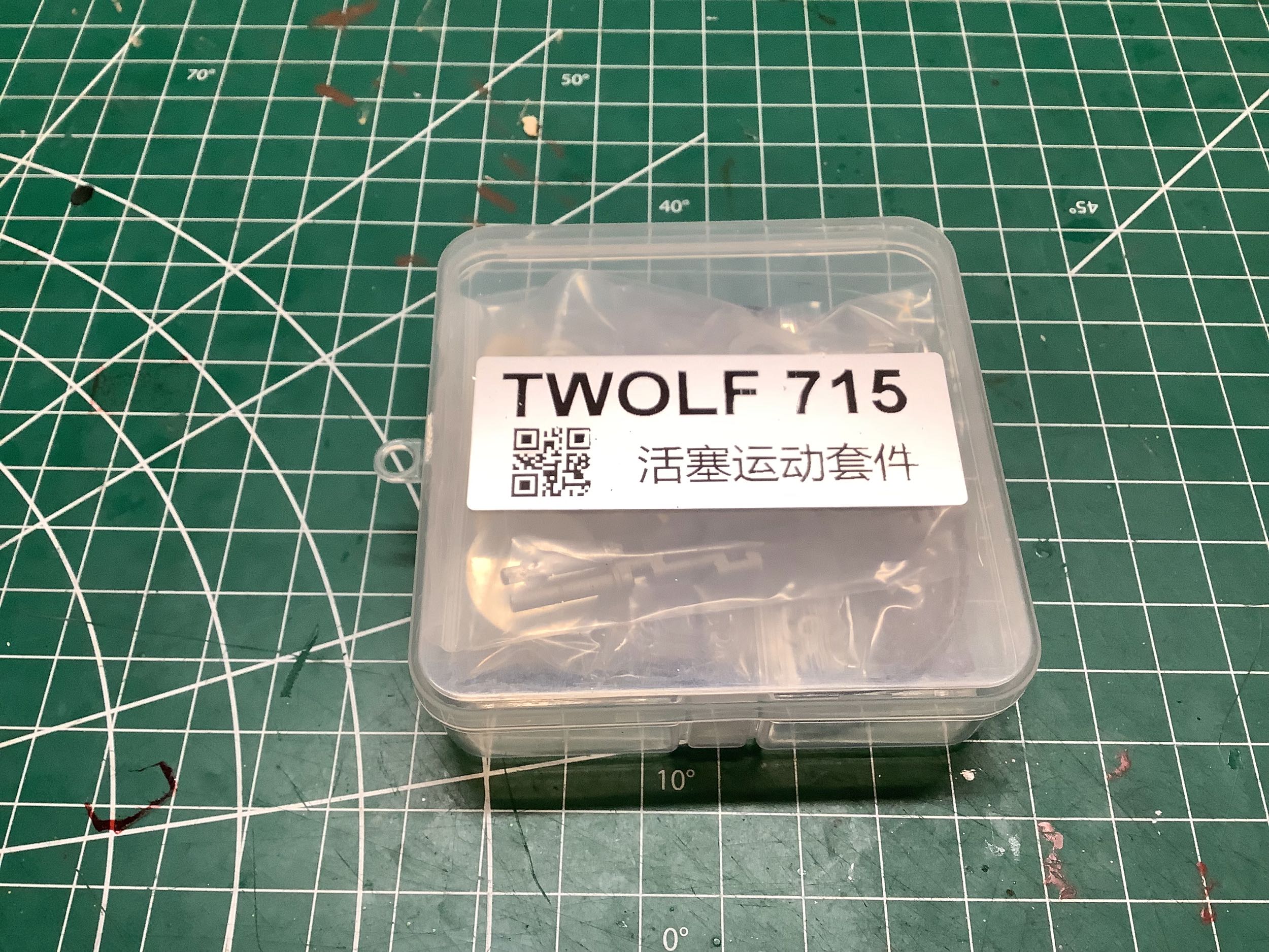
This little plastic box contains the parts for the moving pistons
kit. Although this is considered an optional upgrade, at the time I
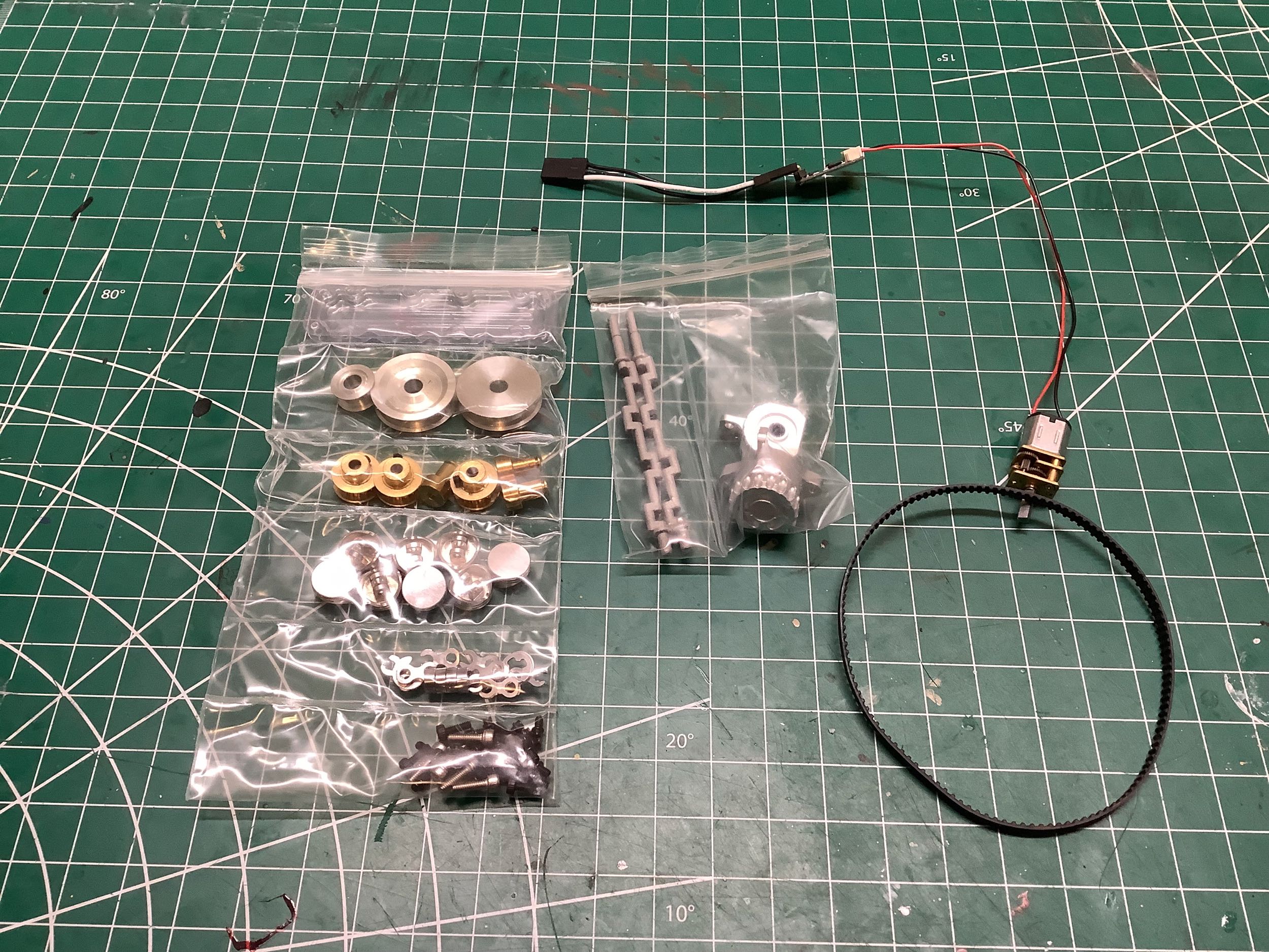
bought my kit this came with it. The layout shown on the right
indicates just how many parts are included in this little kit.
There are 8 pistons, two crankshafts, pulleys, a toothed belt, a tiny
electric motor, and a control unit.
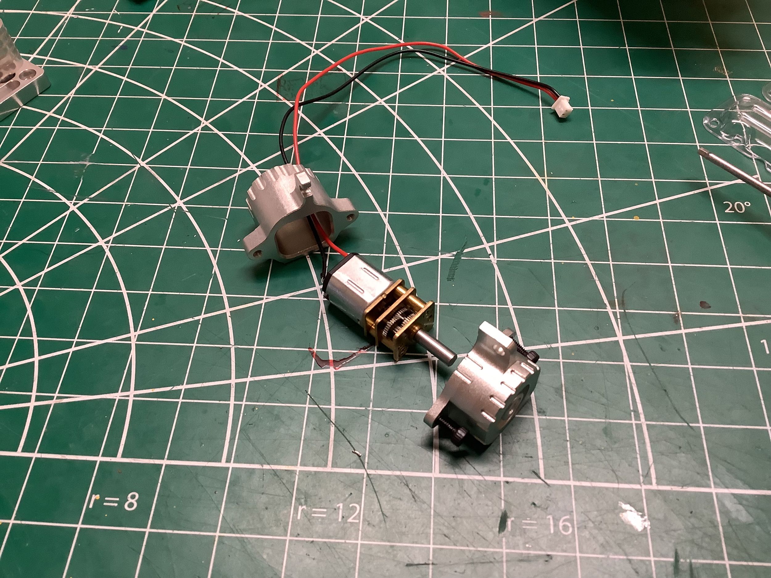
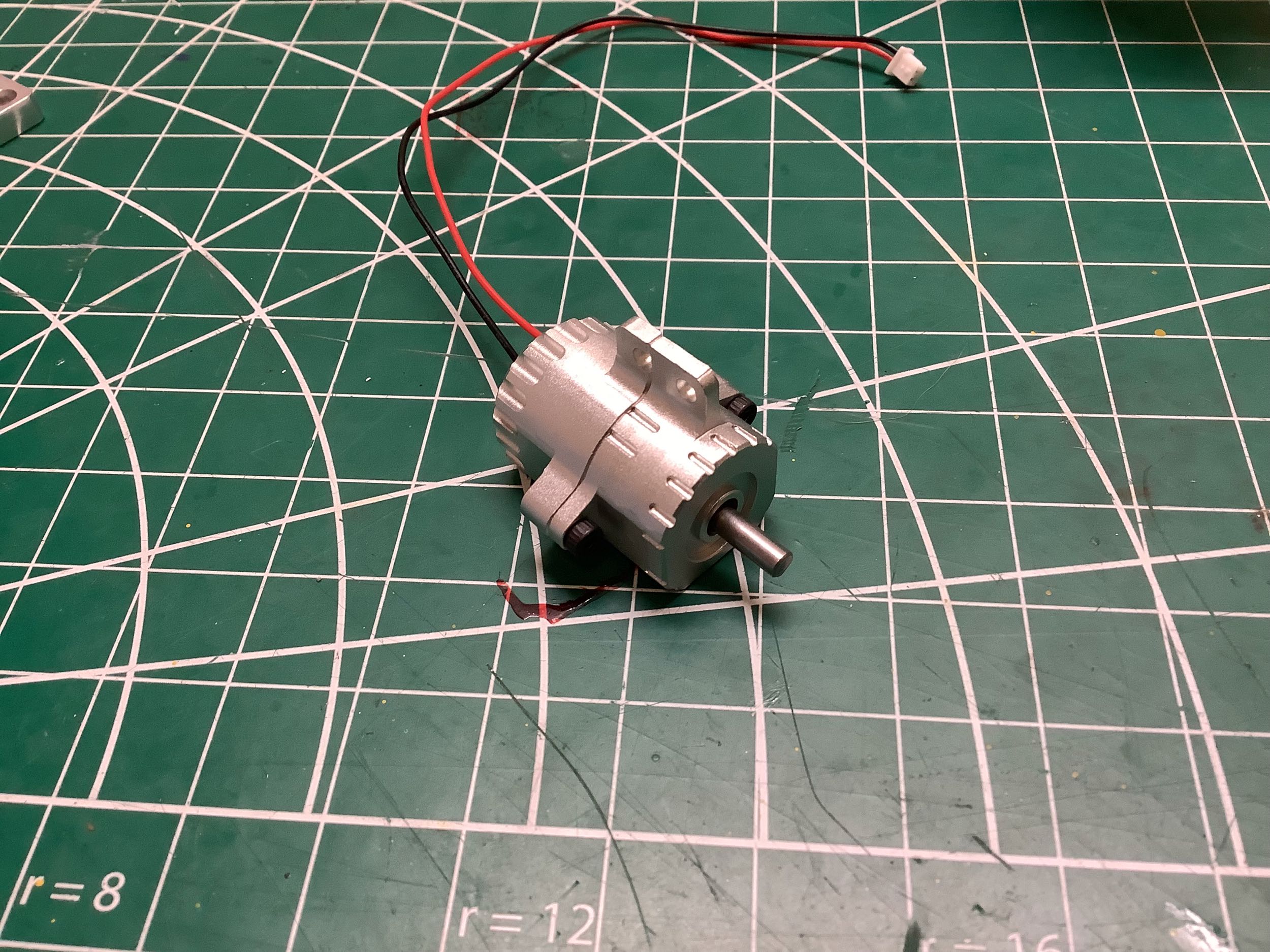
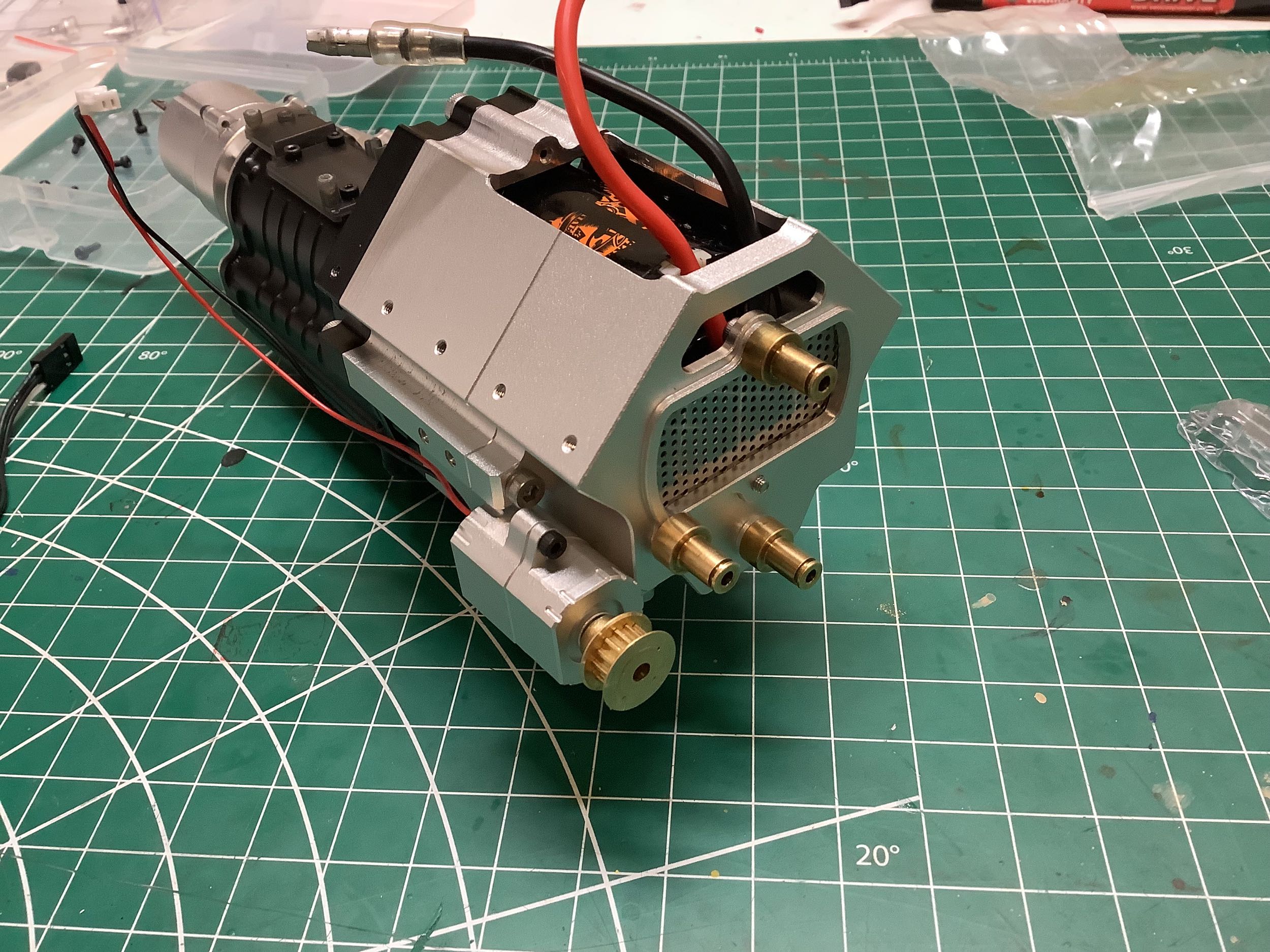
The electric motor has an integrated gear reduction unit so the output
shaft turns quite slowly. The motor sits inside a housing that
probably represents an alternator. I was never really able to
figure out the control unit for this motor. On the JK Max the
controller was set up so you could put it in parallel with the shift
servo and it would run only when the transmission was in neutral.
This one runs any time there is any signal at all so it really requires
its own channel. I had no spare channels so I just skipped the
controller and wired the motor to a manual switch.
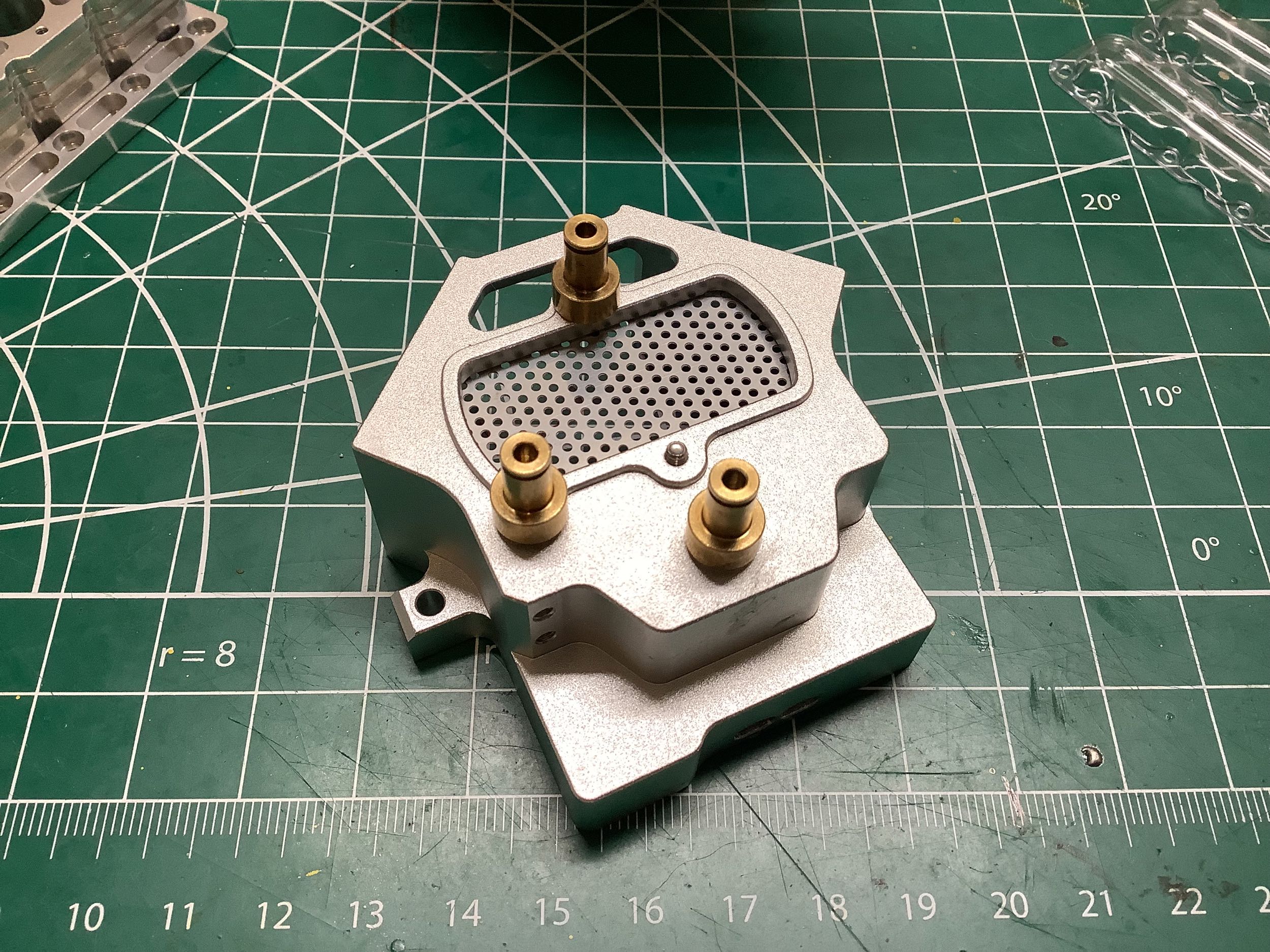
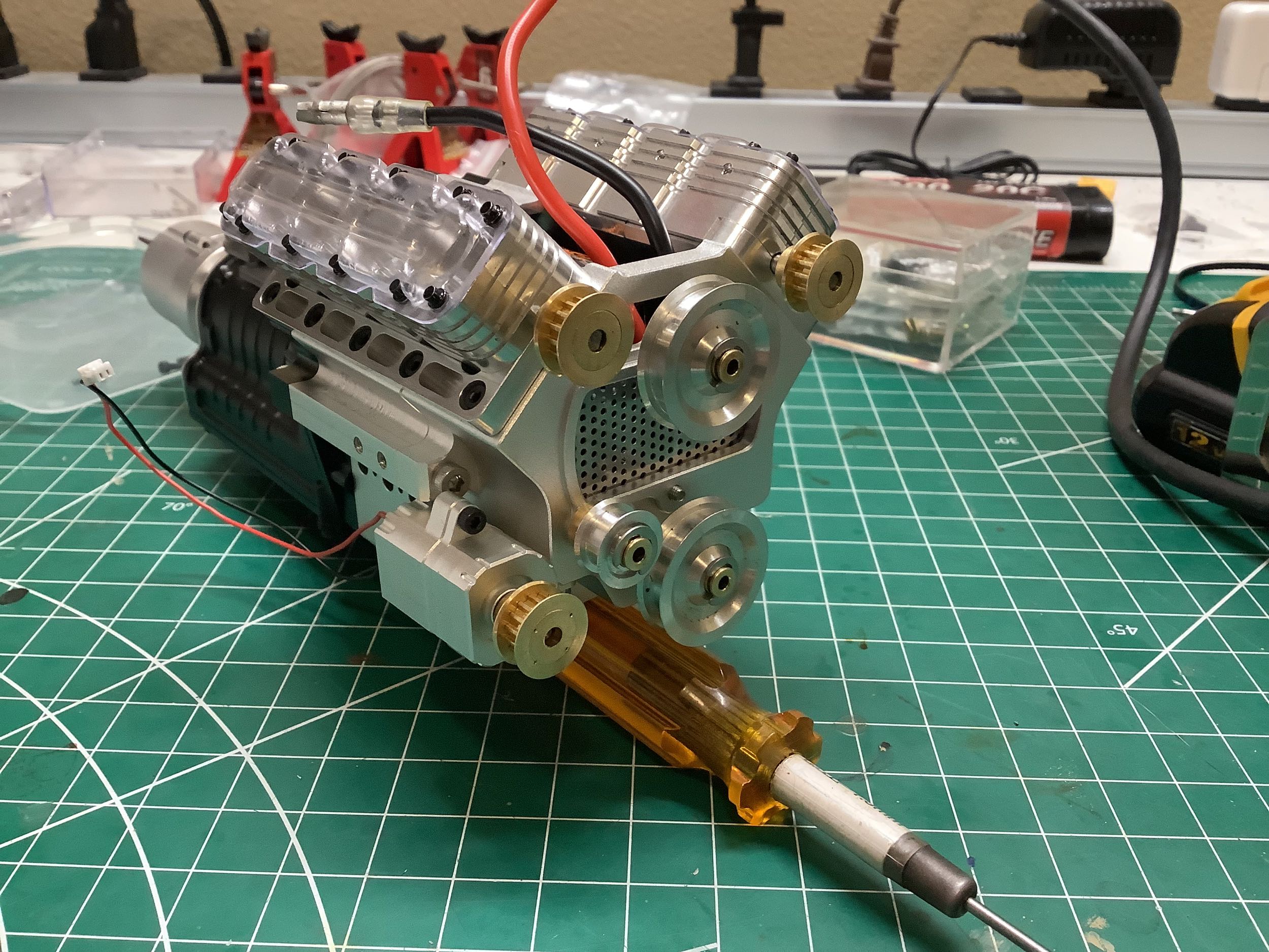
The front housing of the engine block needs to be removed so the three
brass standoffs shown can be mounted. The photo etched mesh which
was previously mounted outside the housing gets moved inside. The
result is shown on the right along with the mounted motor.
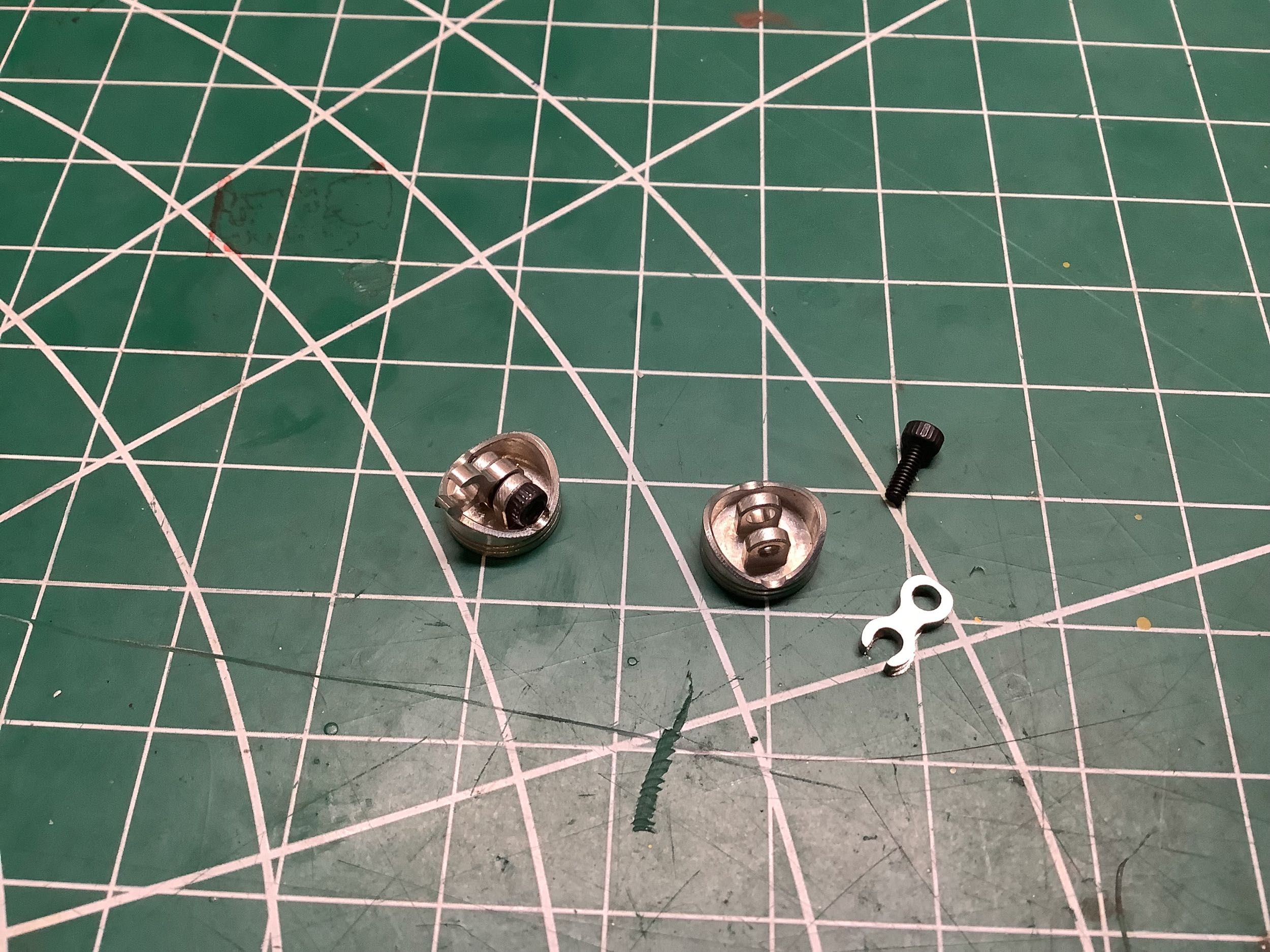
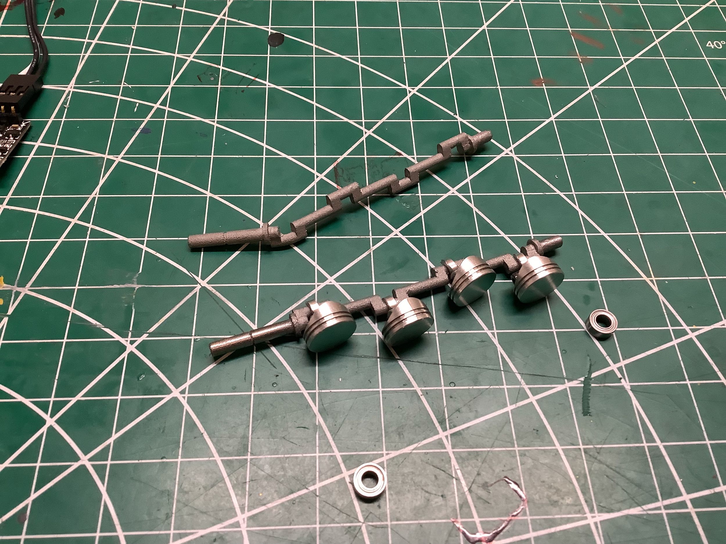
Each tiny machined piston needs to have the connecting rod attached with
a cap screw wrist pin. The big end of the connecting rod is just a
hook which is intended to snap over the crank. The crank is a
cast part with a rough finish and poor tolerances so it is not easy to
get the rods to snap onto it.
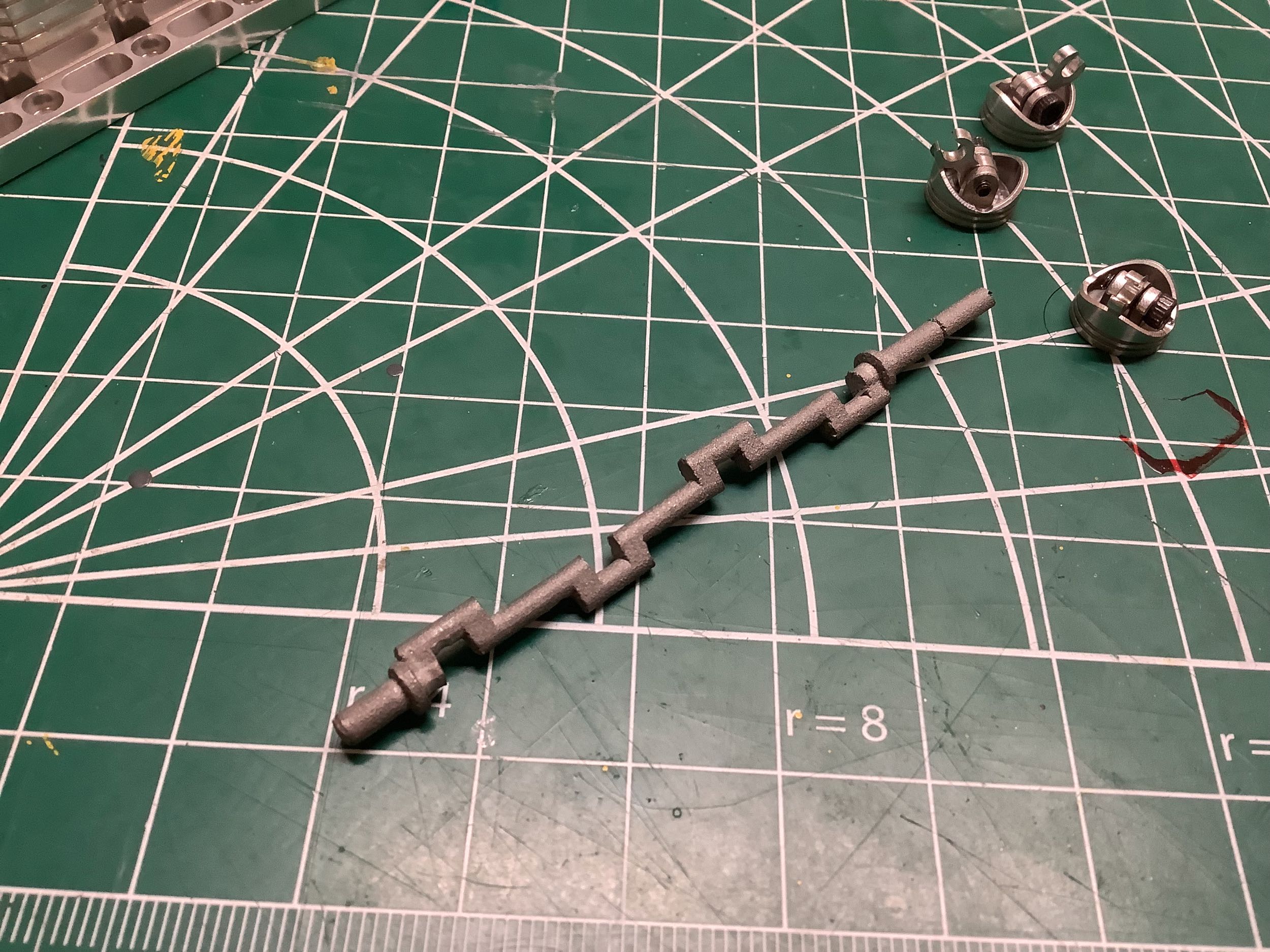
There are no intermediate bearings on the crank, just the bearings at
either end. The outer diameter of the crank ends was too big and
wouldn't fit into the bearings. I had the bright idea of chucking
the crank into my Dremel. I figured I would spin it and squeeze
the other end in sandpaper to grind it down. Big mistake.
The crank immediately bent into a pretzel as shown. I spent a lot
of time with a tiny hammer trying to straighten it out again. The
ends need to be perfectly coaxial or the whole thing will bind.
Once I finally got it fixed, I had to very slowly sand those ends by
hand. It took a couple of hours. I was not thrilled.
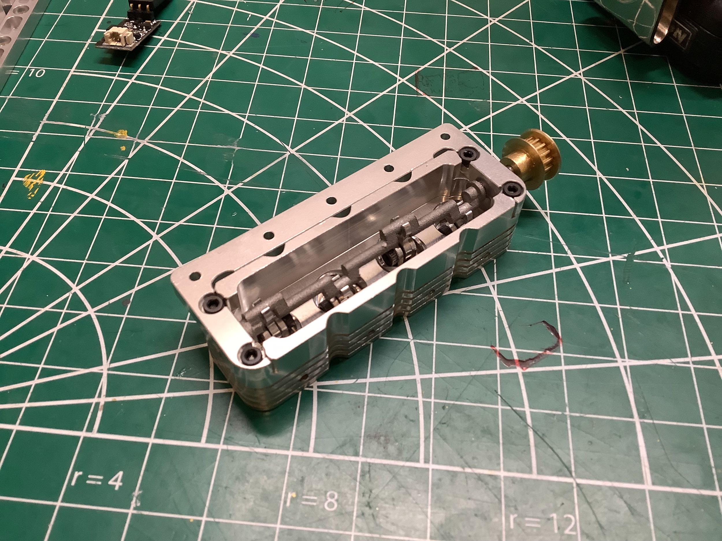
Dual overhead cranks? This is a odd layout. The two banks of
pistons should share the same crankshaft and they should be located
down inside the block. The cam shafts should be up here inside the
heads. Instead this system puts some short stroke pistons inside
the heads with separate cranks. Totally unrealistic, but the
result is moving pistons that looks pretty cool. Each cylinder had
a cross hole in it from the holes drilled for the intake manifold
bolts, and each of those holes had burrs inside the cylinder wall that
needed cleaning so the pistons could move smoothly. Even then, the
pistons probably fit too tightly because the slightest thing makes them
bind. They are very short so they can tip slightly inside the
bore and jam up. Not an ideal system, but the idea is just to look
cool. A toothed pulley is attached to the end of each crank to
drive it.
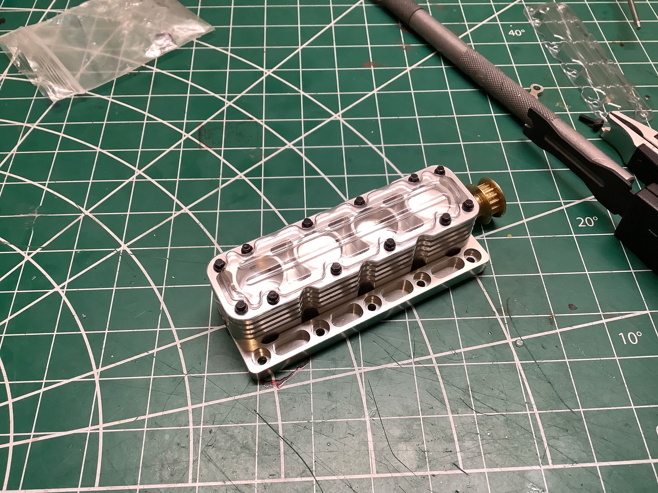
I didn't initially realize that the heads were not perfectly
symmetric. The cross holes for the intake manifold bolts are only
on one side. Naturally I built one of them backwards and had to
rebuild it. After the heads are installed the aluminum idler
pulleys can be mounted. Each of these rides on ball
bearings. There are six pulleys total. The lower one would
represent the real crankshaft (if there was one), and the upper center
is probably a water pump. The other is probably just a tensioner.
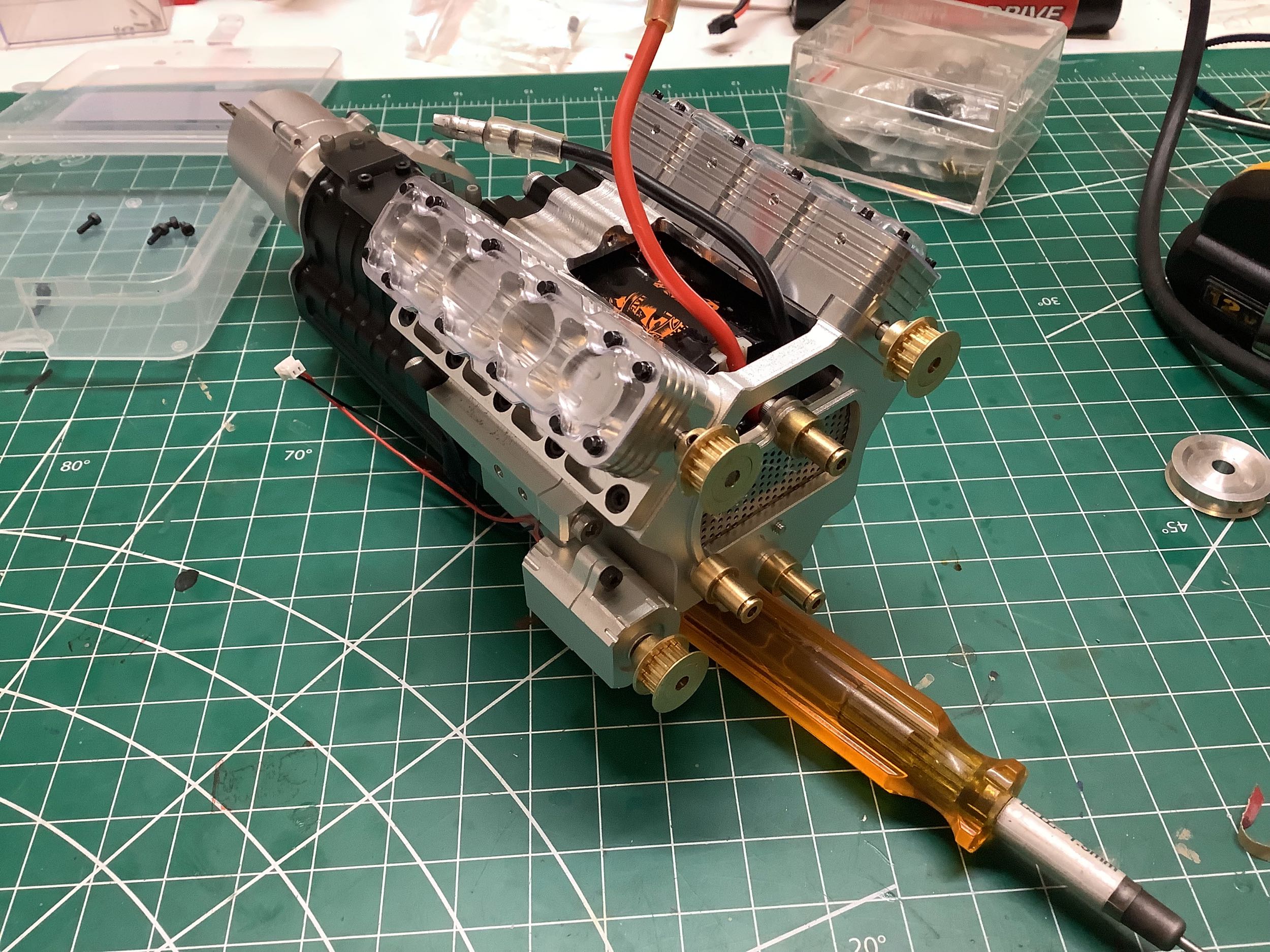
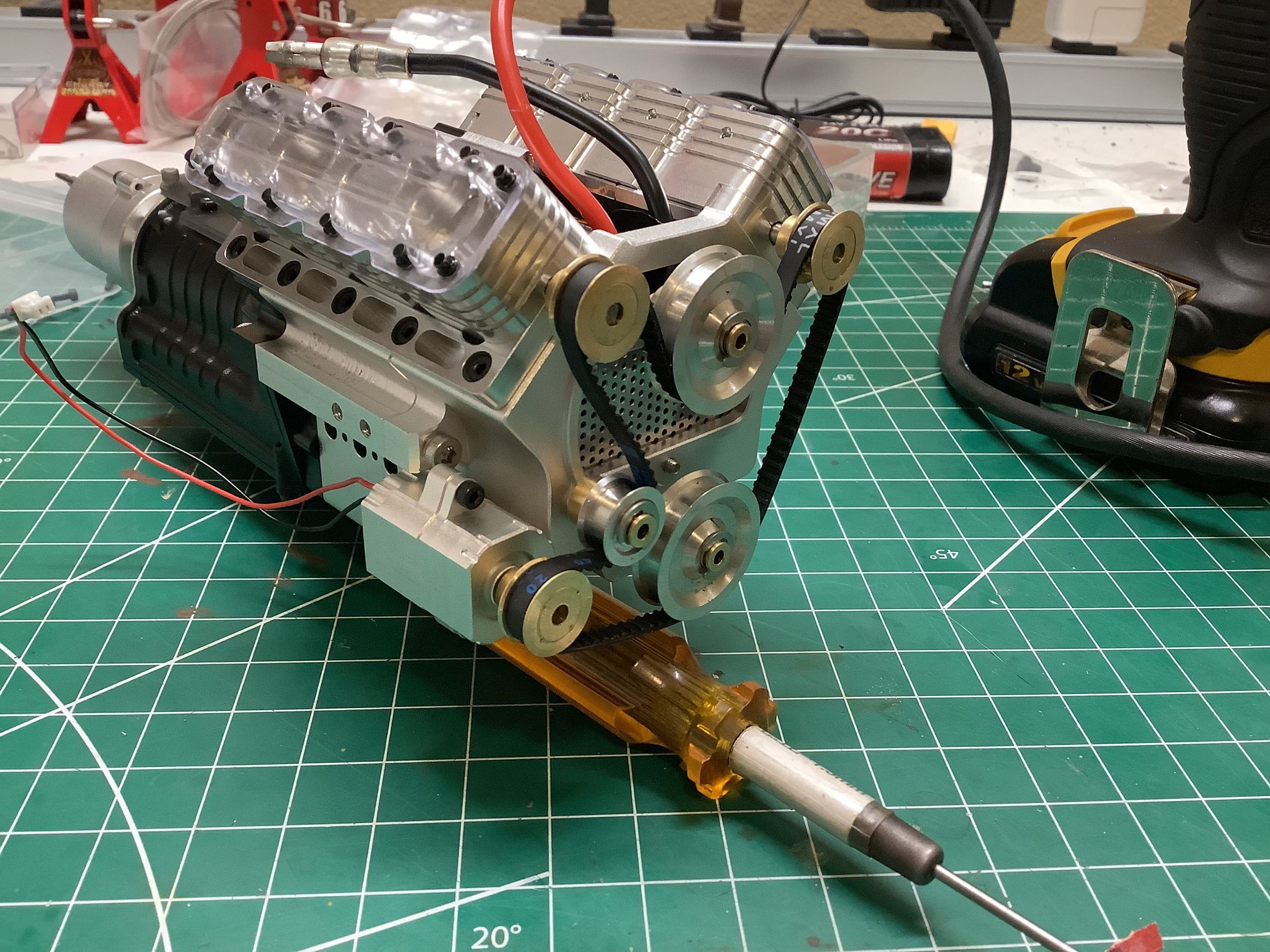
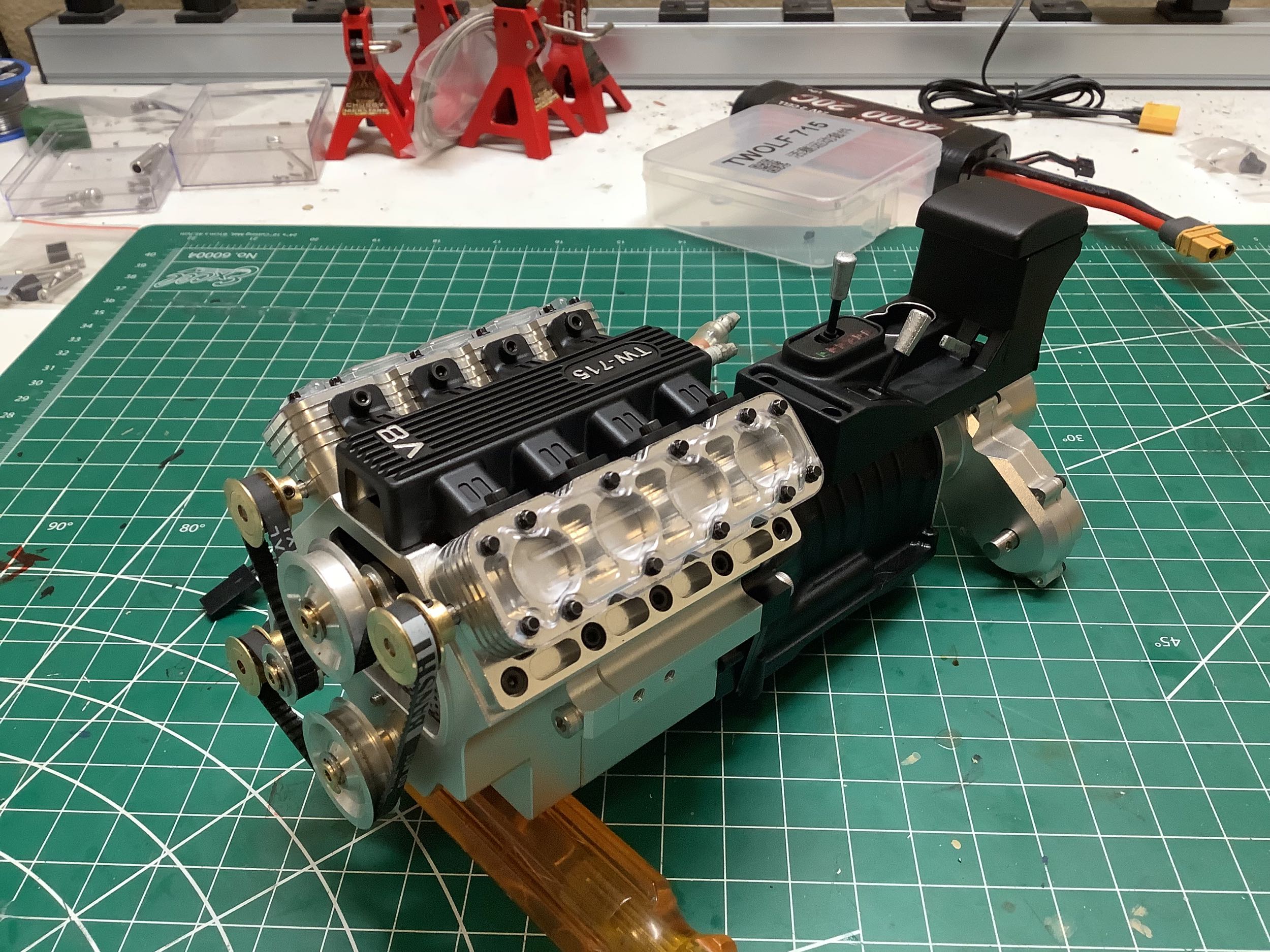
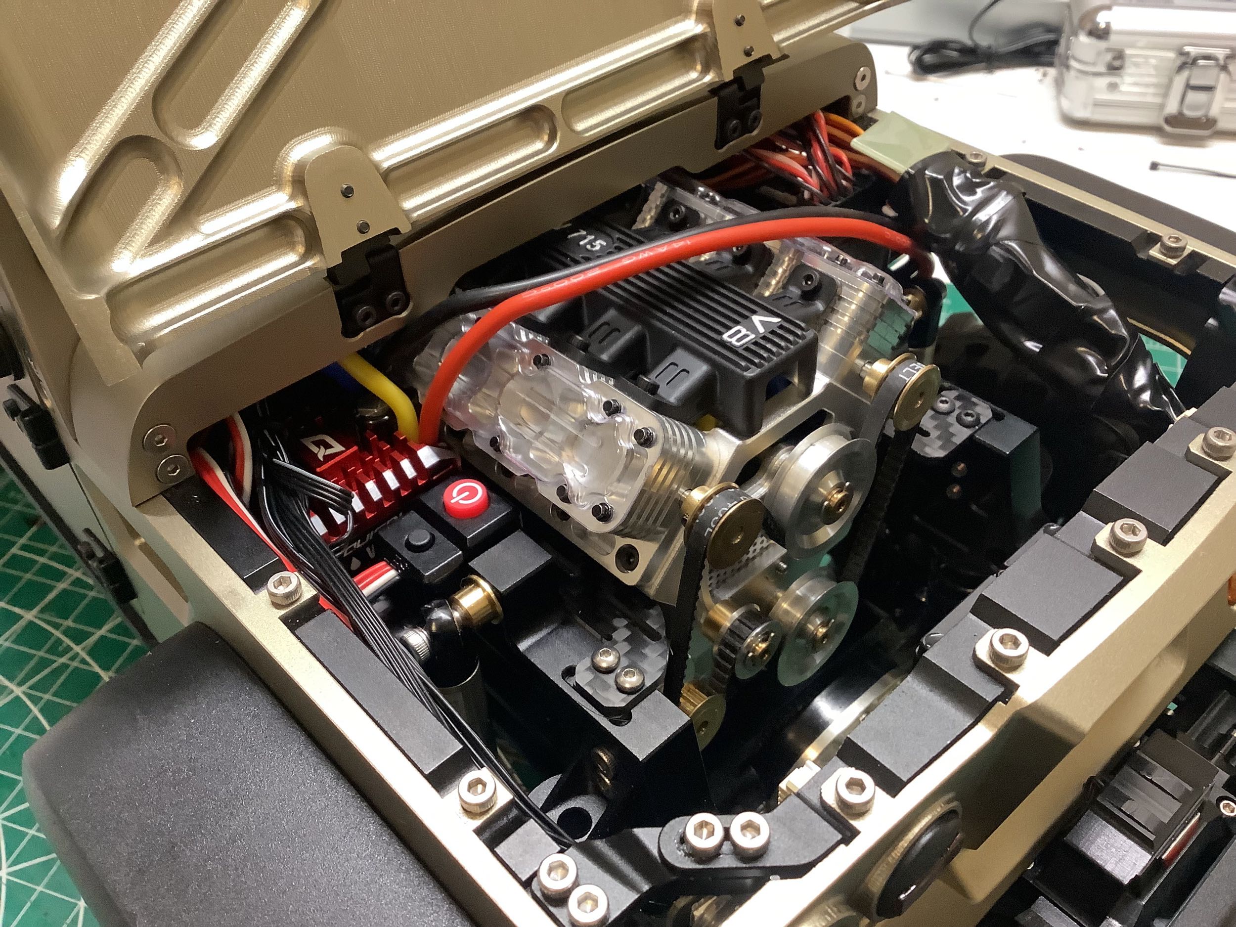
Now I've installed the toothed belt in its serpentine pattern. On
the right I've added the intake manifold which nicely hides all the
wires.
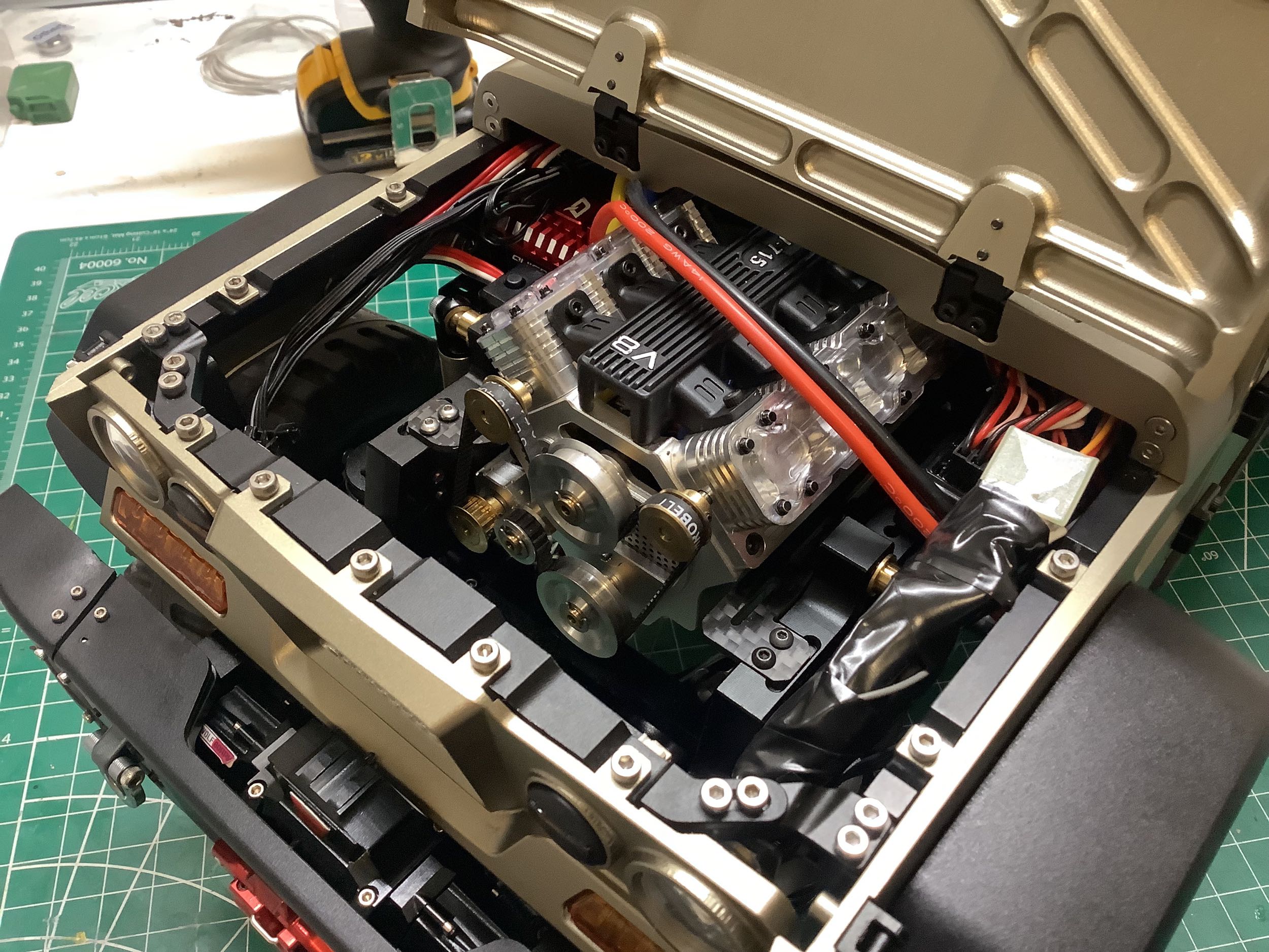
The kit didn't come with anywhere in particular to mount the
electronics, but as an option you could buy a couple of carbon fiber
plates that sit on either side of the engine. That's where I
mounted the ESC, power switch, and receiver. You can also see how
the belt and piston kit looks installed on the model. There is
still plenty of room in front of the engine for a radiator and
fan. Maybe some day.
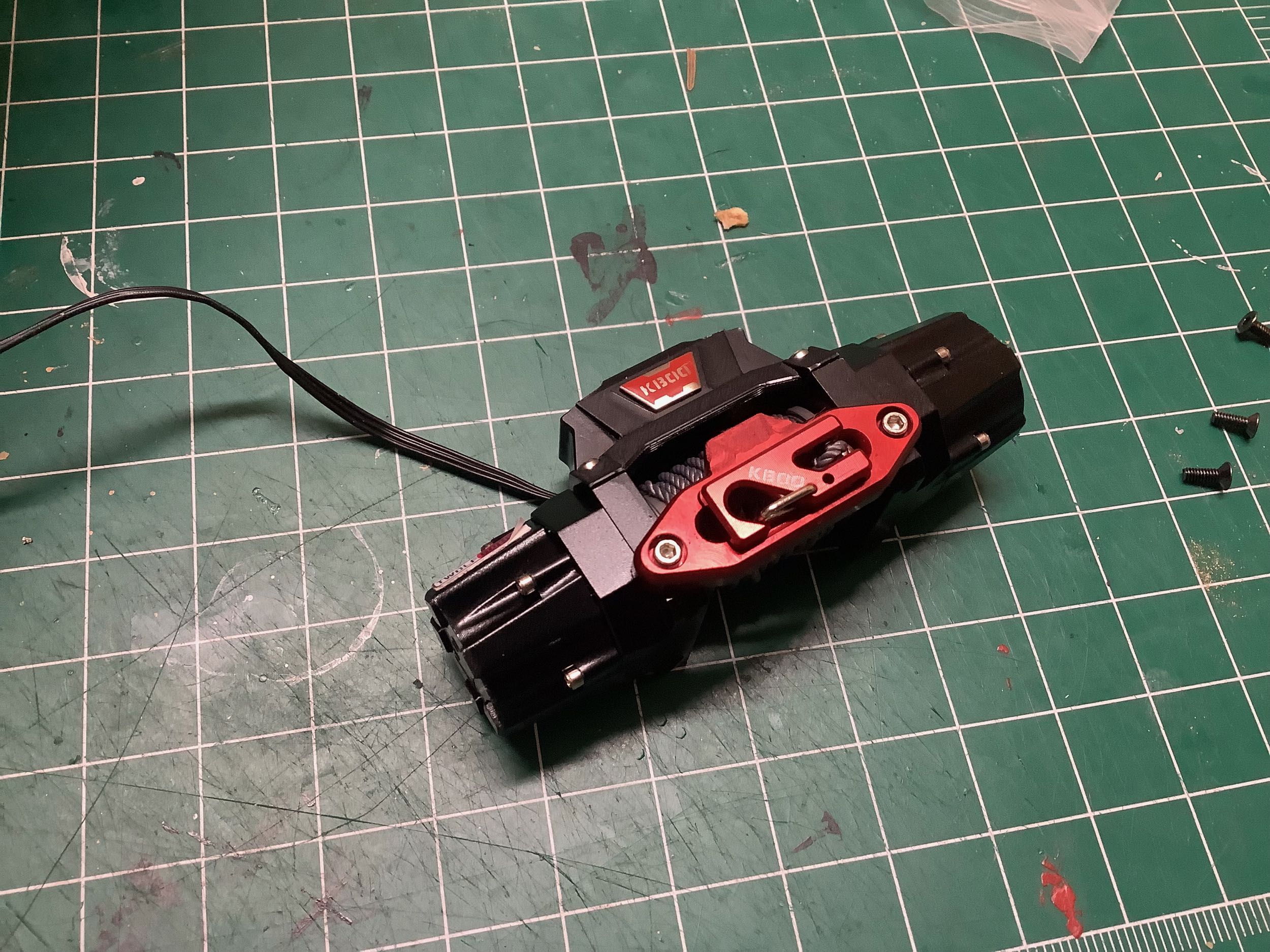
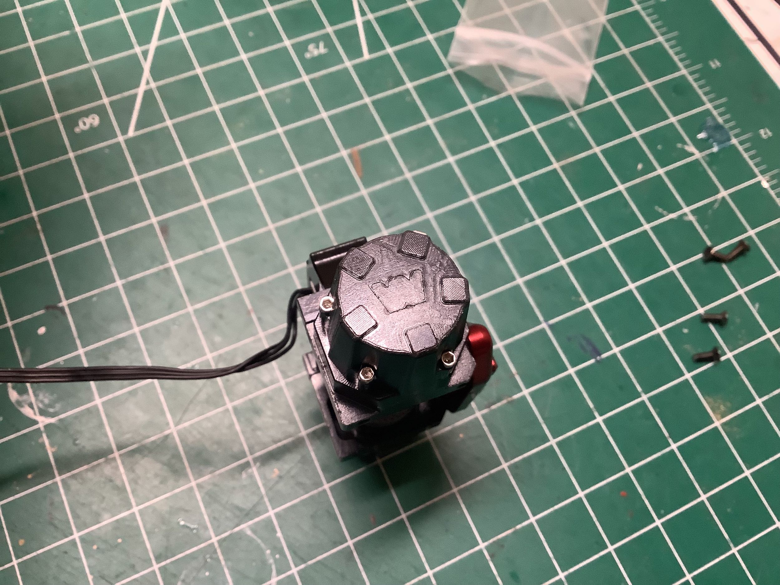
You can't have a vehicle like this without a winch, and this is an
interesting one. The big molded "W" on the front and sides of the
housing make it pretty clear this was intended to be a licensed Warn
winch, but instead it says "K-Boo" on the front. There are two
motors inside and an integrated controller. Out of the box, mine
didn't work at all. There is a ratcheting system inside one of the
housings. This allowed the cable to be pulled out in a free spool
mode, but there was no way to lock it so you couldn't actually retract
the winch. If you rewind the cable so it runs the opposite
direction on the spool then the winch works, but now the ratchet doesn't
do anything. I have no idea how it was actually supposed to work,
but in the end the ratchet system is effectively bypassed.
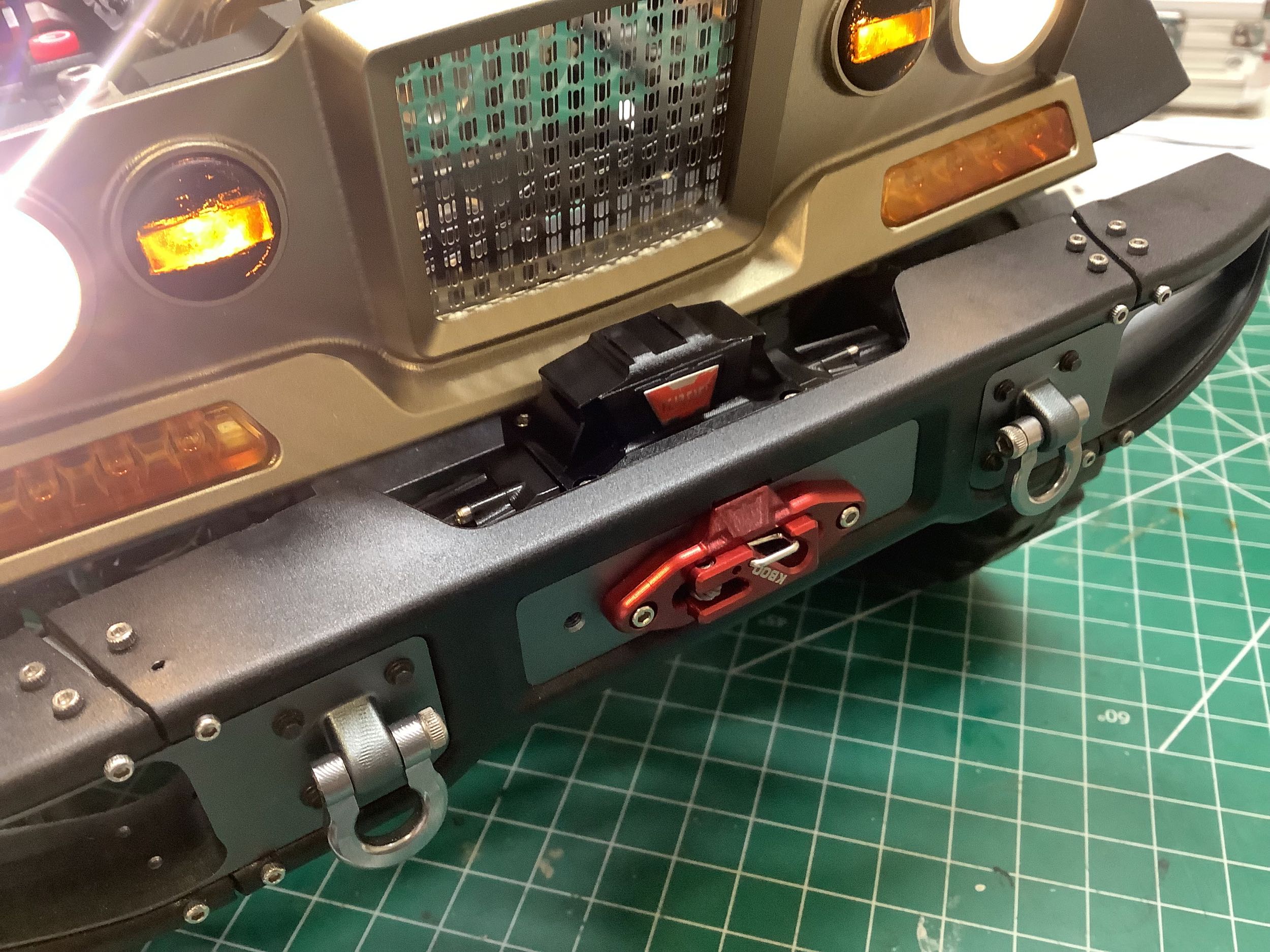
The front bumper had a large cutout made specifically for this winch
which looks just like the real thing. The real truck also has a
rear winch. The rear bumper of the model is provisioned for one as
well. I was going to order two, but upon closer inspection the
cutout is not the same size and the front winch won't fit in the
rear. So far no rear winch is offered. I don't have any more
available channels anyway.
Metal door handles were also an option. This may seem pointless
since they are visually indistinguishable from the plastic versions, but
these handles are actually functional and must be able to turn the
shaft to release the door latches. They were inexpensive so I
figured the metal versions were worth the investment for longevity.
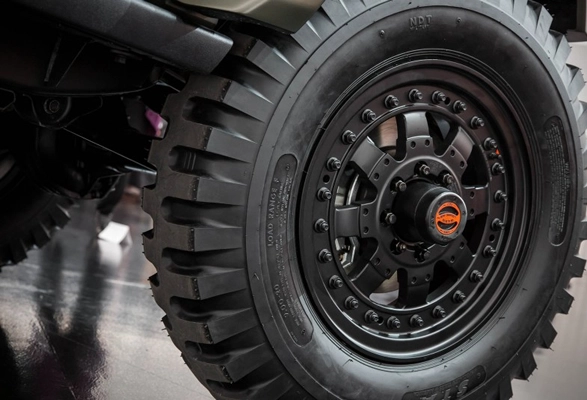
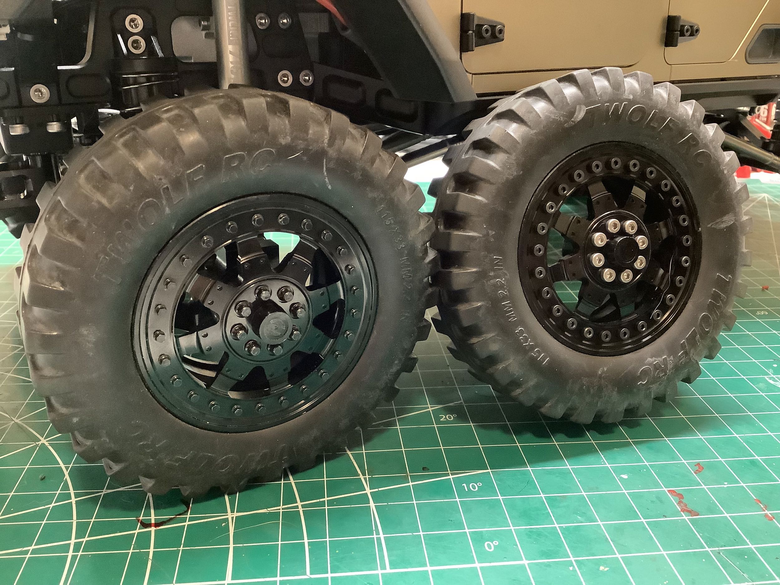
This next upgrade is something I came up with on my own. On the
left is a picture of the beadlock wheels from the real truck. The
wheels from the model match very nicely except for the hardware.
The perimeter used 25 black cap screws with another 8 silver cap screws
to secure the hub. I managed to find some tiny (M2 and M2.5) black
hex bolts to use instead. The far right shows how a wheel looks
out of the box, and the center wheel contains my hex bolts. I
think it looks much more like the real thing. They took forever to
install though.
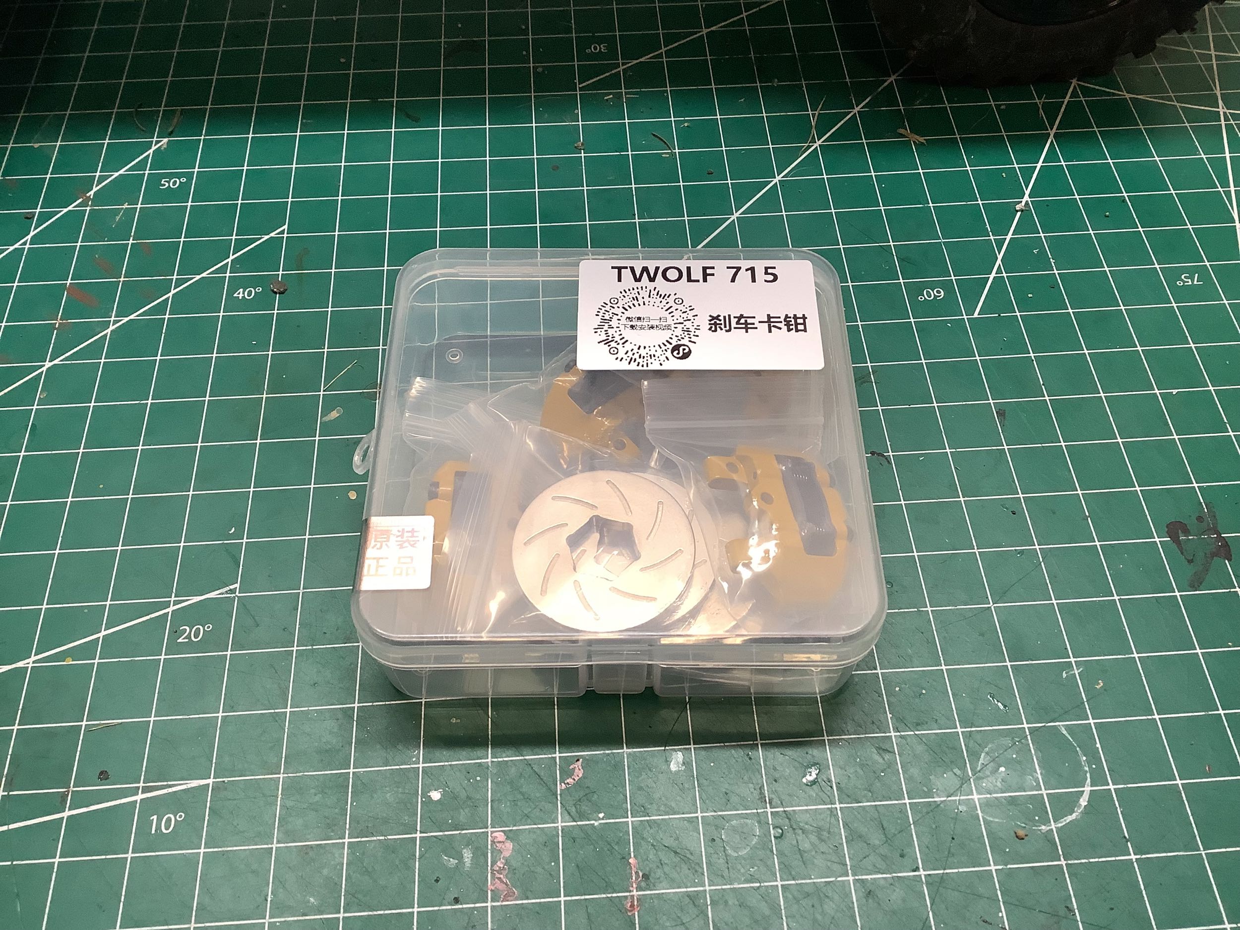
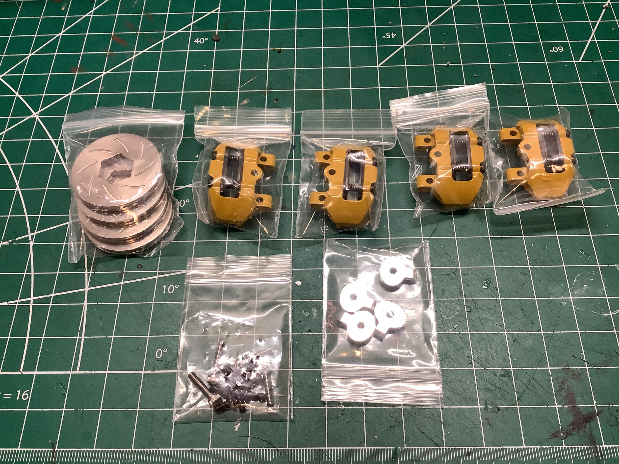
As long as I'm installing useless and expensive upgrades, why not add
some unsprung weight with these scale metal brake discs and
calipers? This little kit came in a nice plastic box with
individually bagged parts.
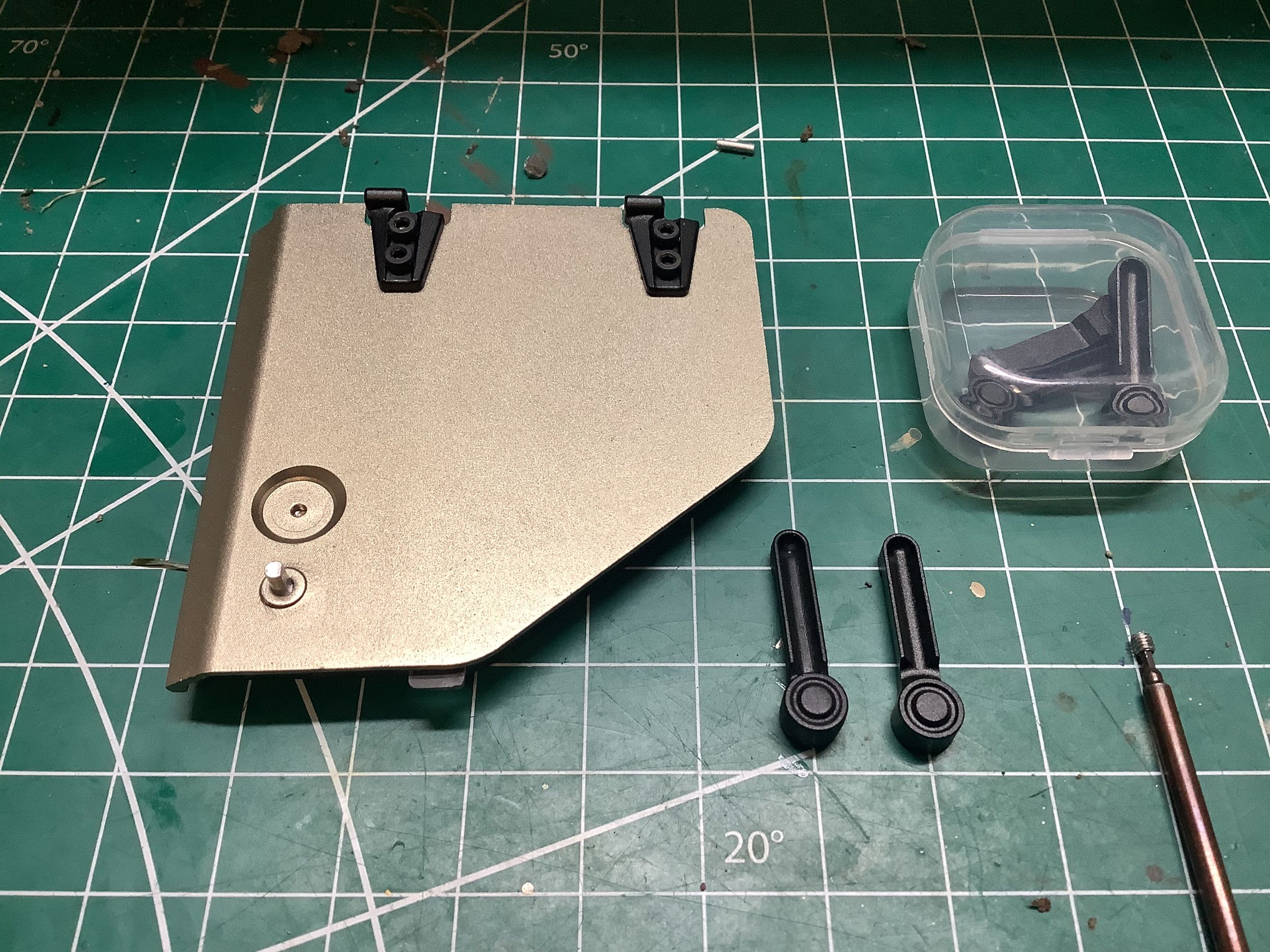
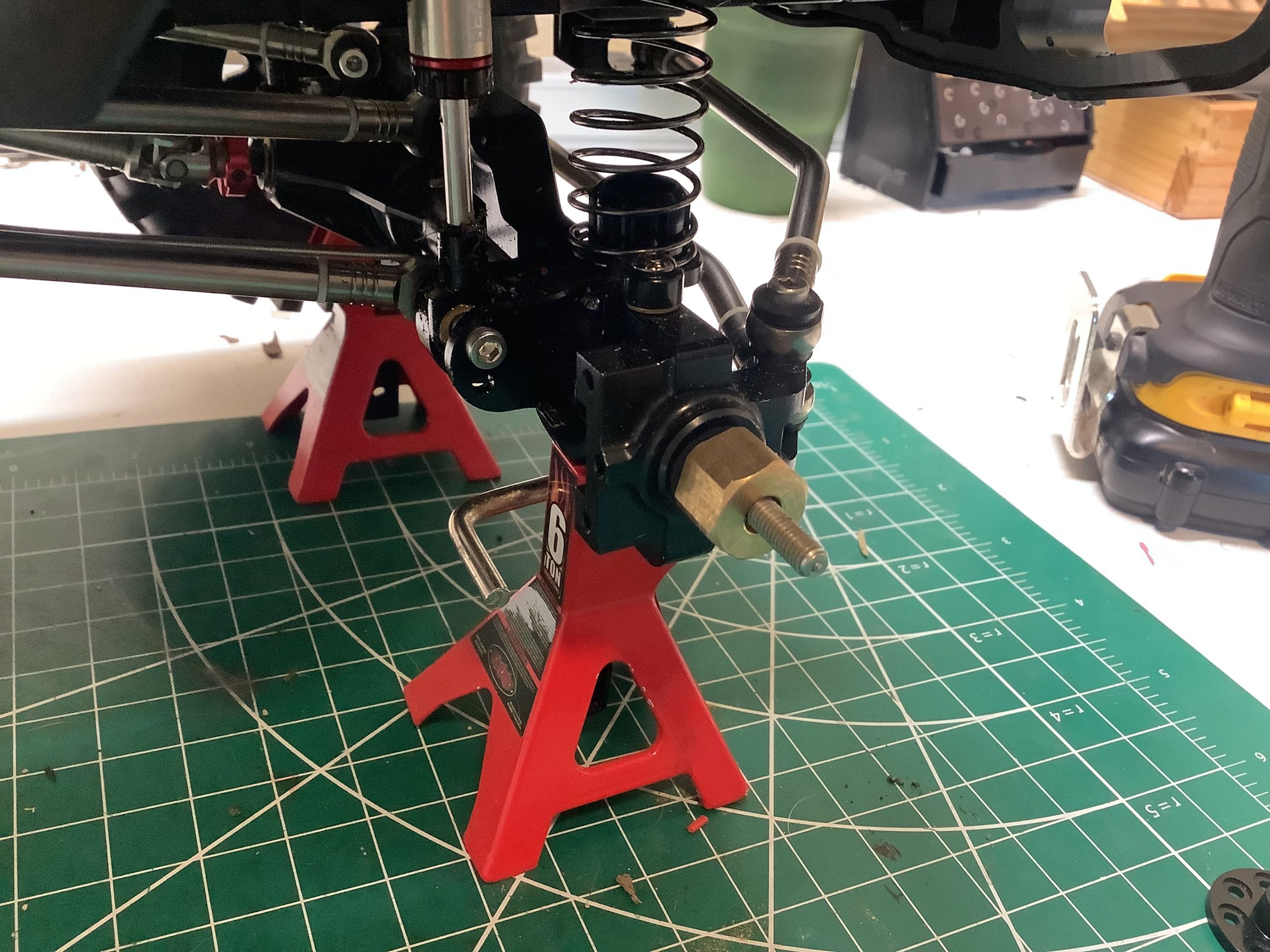
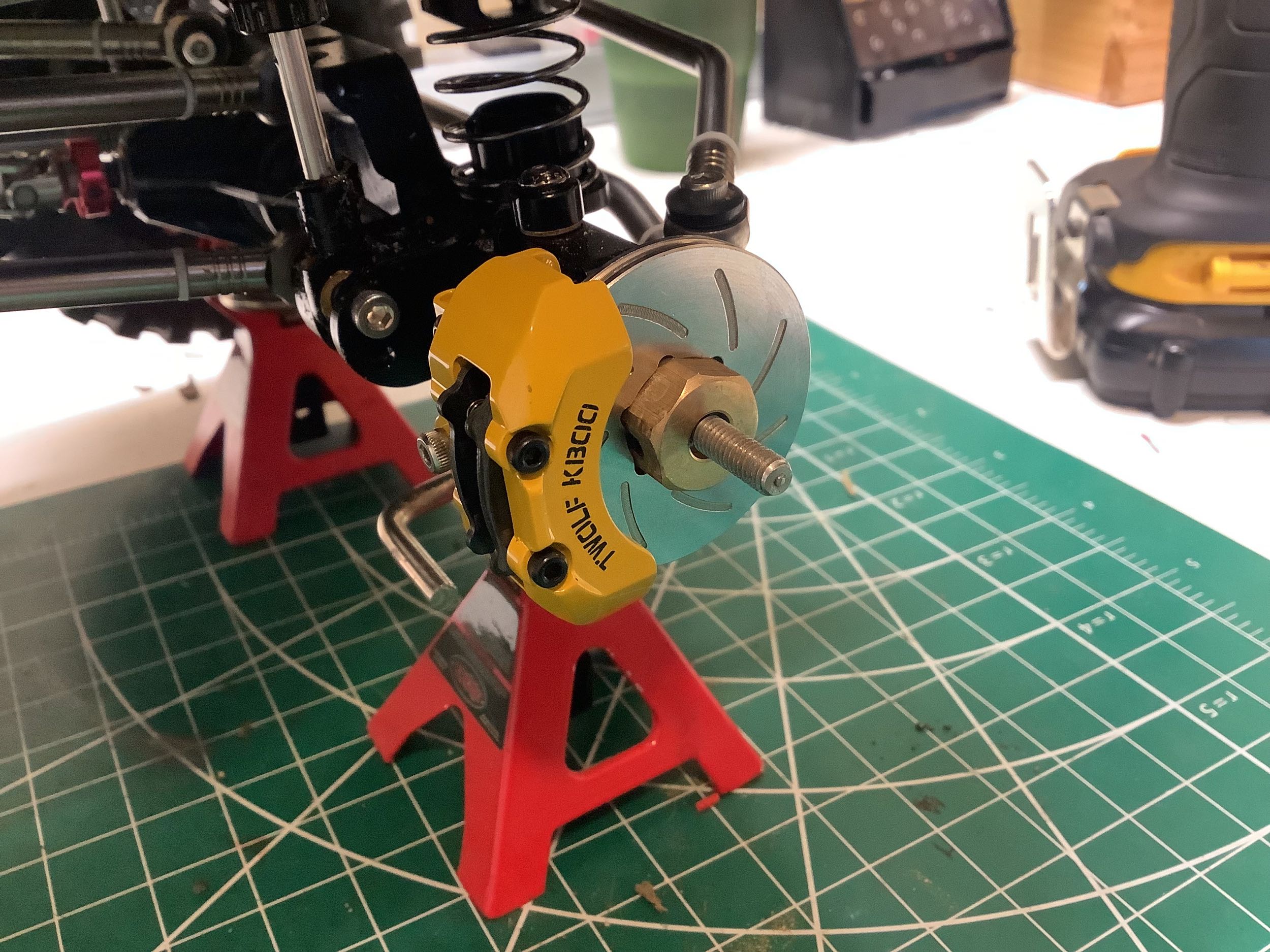
The left hand picture shows an axle before the brake system was
installed, and the right hand picture shows the completed
installation. That solid metal rotor spins with the wheel
hex. The caliper is screwed to the axle housing, and that means
the rotor correctly spins relative to the fixed caliper. There are
actually carbon fiber brake pads within the caliper and a little crank
to squeeze them, so it conceivable that you could make these brakes
functional.
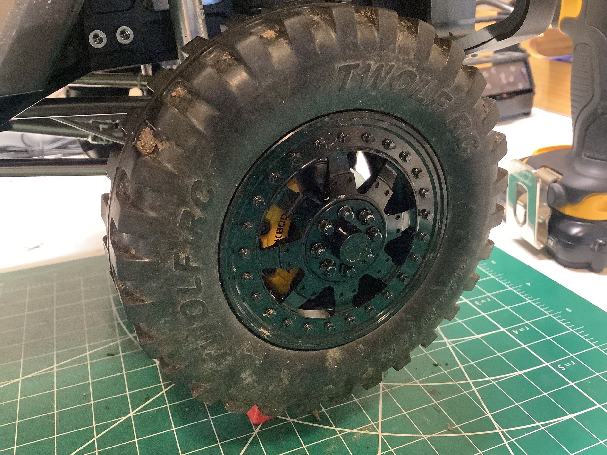
Here is what the brakes look like through the wheel. They are not
super visible, but I know they are there. I suspect they will do
more harm than good once I get into some mud.
©2022 Eric Albrecht