TW-715 Project
Page 7: Installing the Electronics

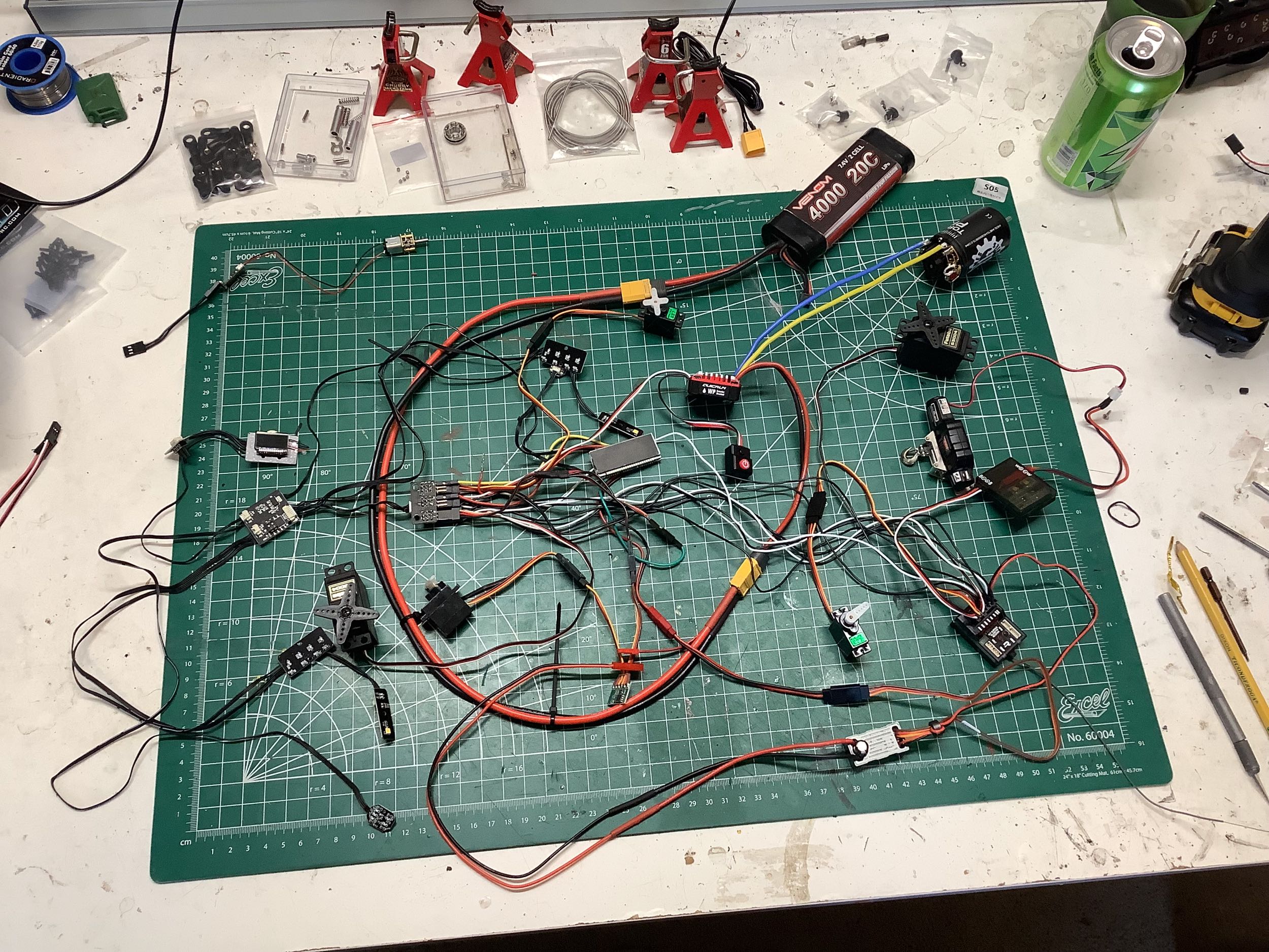
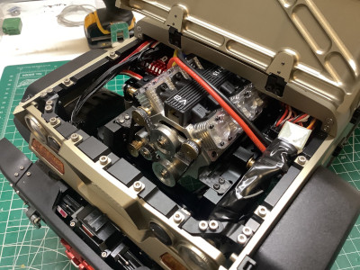
There is a reason I left the electronics until the very end on this
model. There is a tremendous amount going on here. The above
picture shows my first attempt at connecting everything together, and
even this is a simplified version for reasons I'll discuss
shortly. As a baseline, here is the channel breakdown:
- Channel 1: Steering. I originally planned to use a
ProTek Black Label 370TBL with 650 oz-in of torque at 7.4V powered by a
Hobbywing 10A UBEC. I needed a Y-harness to run the steering wheel
servo
off the same channel where I installed a Protek high voltage micro
servo. The steering wheel turns the wrong direction compared to
the axle, so I installed a servo reverser in series with the micro
servo.
This channel also needs to run to the lighting system so the turn
signals know when to flash. The instrument panel also indicates
the turn signals.
- Channel 2: Throttle. This carries the power from
the
Hobbywing 1080 ESC to the receiver. When using an external BEC,
the positive wire to the receiver would be disconnected.
This channel needs to be split
to the lighting system so brake lights can work. Instead of
traditional white reverse lights, the tail lights flash when backing
up. The headlights also get brighter when moving forward.
Finally, the throttle position is shown on the tachometer on the
instrument panel.
- Channel 3: Transmission. This controls shifting of the
2 speed transmission with a Protek high voltage micro servo. This
needs to be split to the instrument panel which indicates selected
gear. This is mapped to a 3-position switch with neutral in the
center. I discovered later than multiple shift inputs switch the
lighting system between modes: all off, indicators only, all on.
- Channel 4: Transfer Case. This controls a Protek
high voltage micro servo to shift between RWD and 4WD. This is
mapped to a 2-position
switch.
- Channel 5: Locking Differential. This
controls an EcoPower 120T with 400 oz-in of torque at 7.4V to pull the
differential locking cables. Both front and rear axles lock
together. This is mapped to a 2-position
switch.
- Channel 6: Winch. This is used to drive the
winch. The winch is powered from the receiver rather than directly
from the battery like some other winches. This is mapped to a
3-position momentary switch.
If you were reading closely you may have noticed that I was intending to
run the entire system at 7.4V from a UBEC. When I hooked
everything up the steering wheel didn't work, and I eventually
discovered that my servo reverser only functioned at up to 6V. My
next plan was to run almost the entire system off the 7.4V UBEC but run
the steering wheel servo only from the 6V BEC in the ESC. This
would have been quite painful to wire. While experimenting, I
discovered that an external UBEC wasn't really necessary. The
Hobbywing 1080 ESC has a maximum of 6A of output which was plenty
without any brown out problems, so I just eliminated the UBEC from the
circuit entirely. Later I got a higher voltage servo reverser
allowing me to switch the internal BEC back to 7.4V. The
instrument panel includes a battery charge indicator, so that meant I
had to split power directly off the battery with a JST connector to
power the panel. Luckily it is capable of 2s or 3s voltage so I
have battery options. I also eventually realized that my temporary
EcoPower 120T steering servo had plenty of torque so there was no
reason to spend an additional $100 on the Black Label.
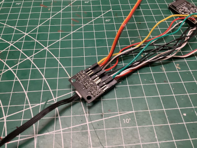
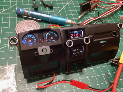
The lighting system and instrument panel were a big surprise because
they were not documented at all on the web site or promotional
material. The PCB shown on the left is a splitter for Channels 1-3
with additional outputs to an external lighting board and an
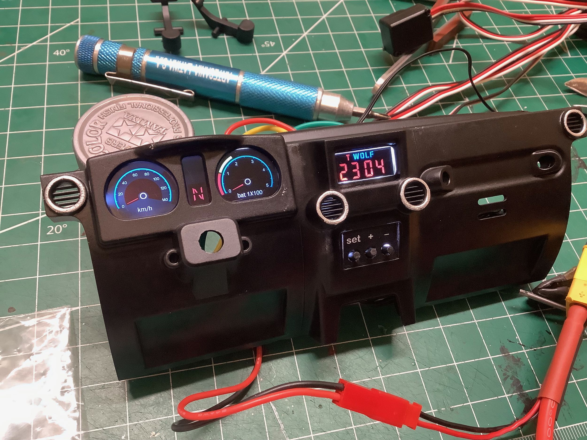
instrument panel. That instrument panel is shown on the
right. The speedometer, tachometer, and the area between are all
part of a single rectangular panel. Let's start with the center
area. That "N" in the center is indicating that the transmission
is in neutral and it will change to 1 for Low and 2 for High. The
upper portion of that area is currently blank but it has green arrows
for when the left or right turn signals are flashing. The
tachometer is on the right and it indicates throttle position. The
ring around the outside of the tach indicates battery charge. The
red and yellow arcs shown indicate semi-low battery. Additional
green arcs would be present for a more full battery. The
speedometer on the left doesn't really indicate speed, but it parallels
the tach when the transmission is in gear. It is smart enough not
to show anything on the speedo when the transmission is in
neutral. The speedo does not indicate any more speed in high gear
than in low gear even though it has all the necessary information to do
so. The additional panel in the center of the dash is a
clock and the three buttons beneath it are for setting the time.
There is a button cell battery in the clock PCB so it remembers the time
even without a battery in the model.

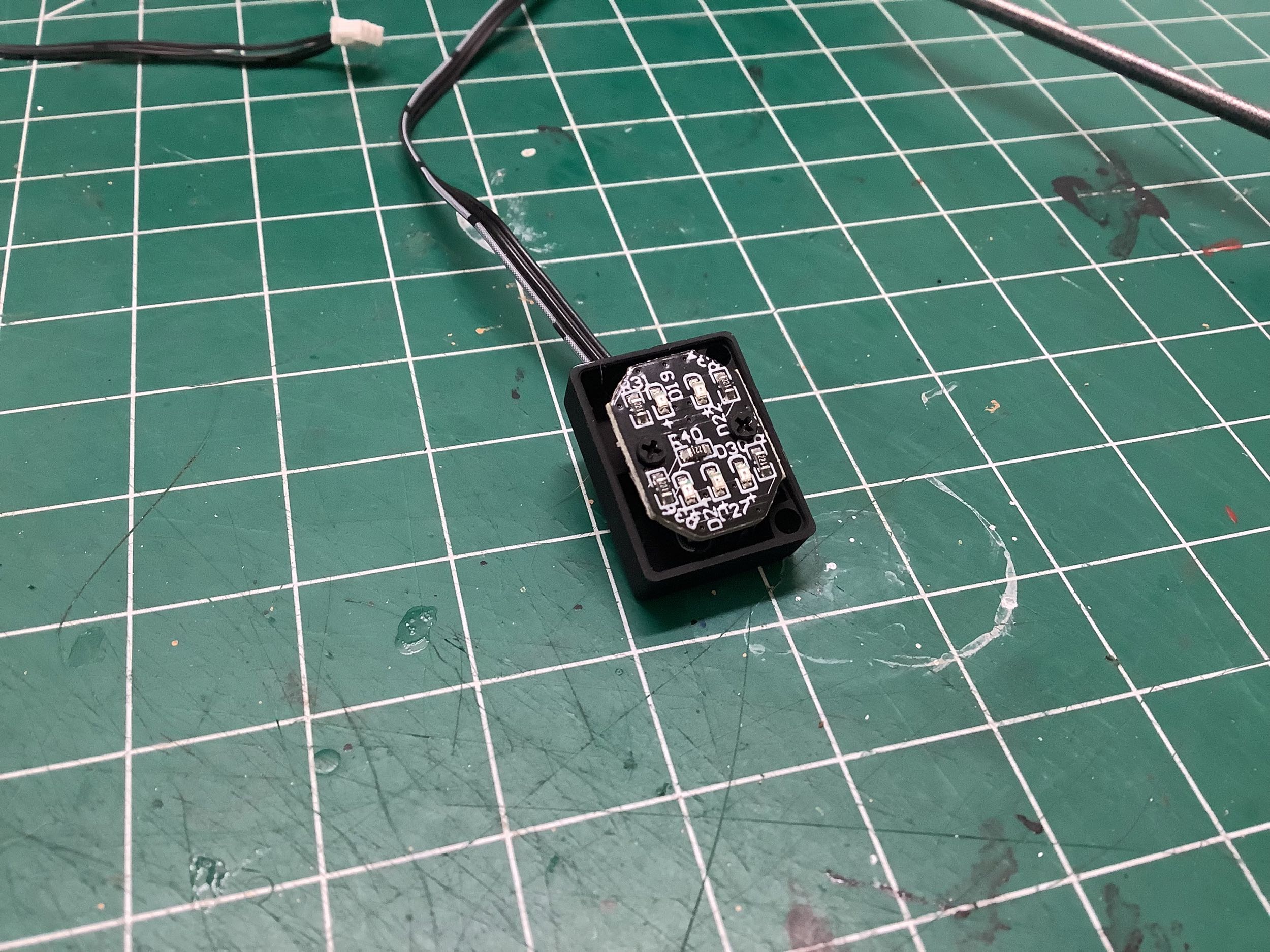
This model doesn't use individual 3mm or 5mm LEDs for lighting, instead
everything uses chip mounted LEDs. On the left you can see the
backs of the boards for the headlights. The turn signals each
consist of 5 LEDs that move sequentially to indicate turn
direction. It's pretty cool.
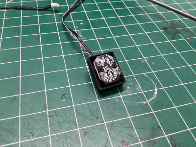
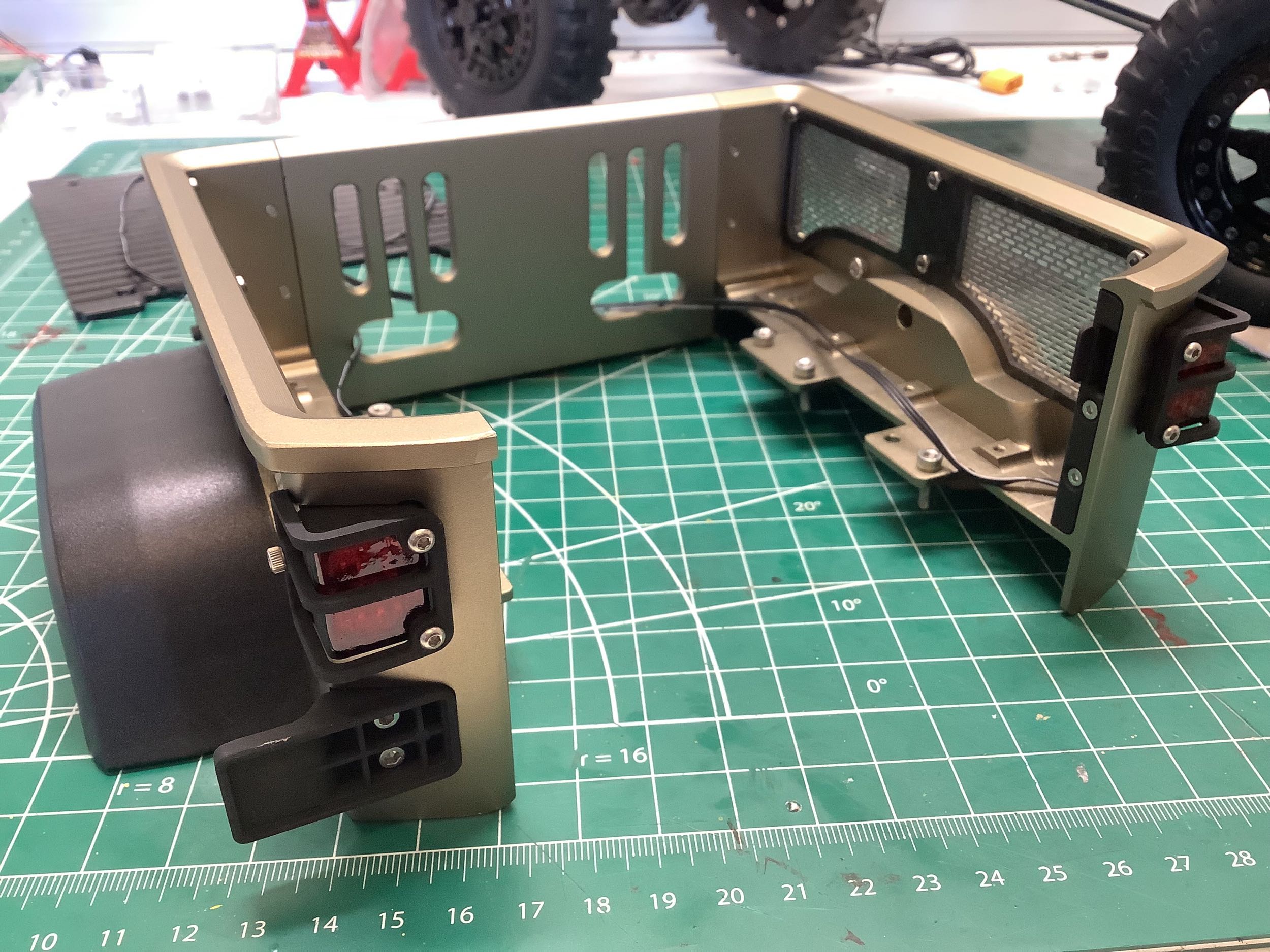
There are 5 chip LEDs for each tail light as shown. The two on top
are red and are used for tail lights, brake lights, and reverse
flashers. The three on the bottom are amber and are used for turn
signals. The amber seems to show up OK through the red painted
lens. The wires can
be completely hidden behind the plastic tail panel and then under the
bed deck.

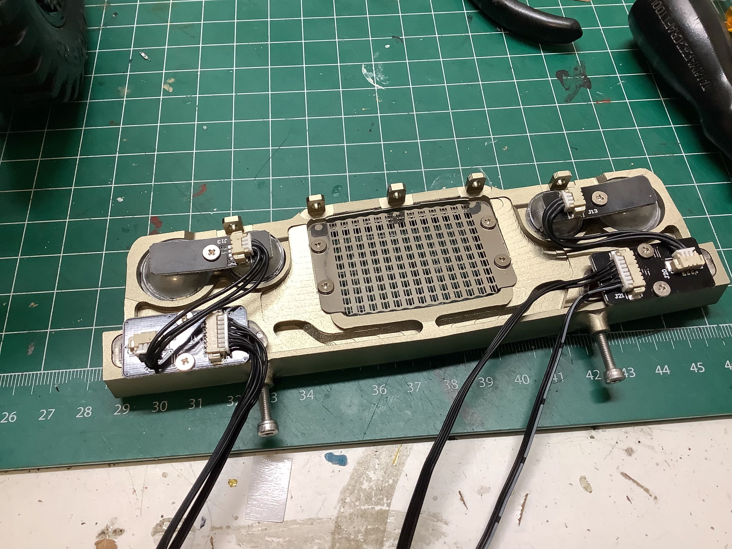
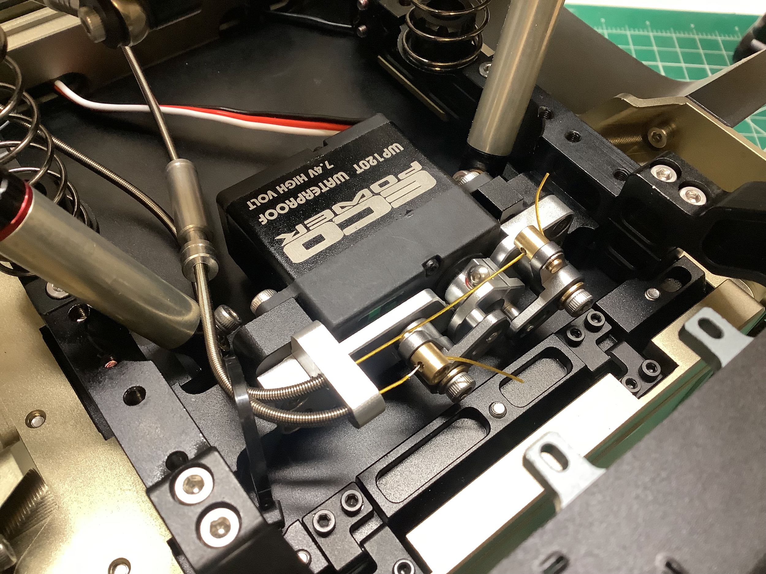
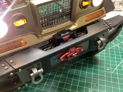
I procrastinated doing the diff lock cables until the very end, but it
turned out not to be all that difficult. Again, there was
absolutely nothing about how to do this in the basic instruction
videos. There was a separate video just for rigging the cables,
but it was only in Chinese. This photo shows how the cable shrouds
terminate and how the cables clamp to the actuation mechanism.
There are spring cartridges in series with each cable that help to
reduce the load on the servo when the locks are engaged.

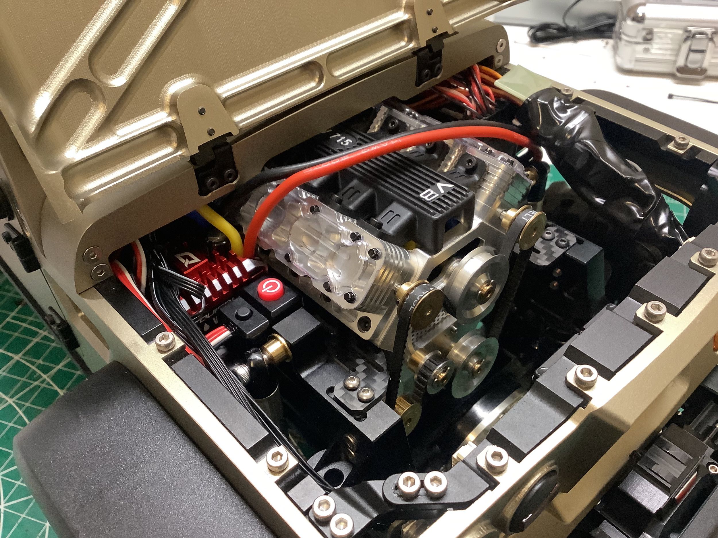
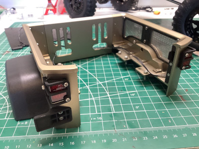
These pictures show the best I was able to do to consolidate and hide
all the wiring. The piles of servo connections are inside that
bundle of electrical tape. That wire running over the top of the engine
is the battery cable. I ran out of bandwidth in my brain to do any
more work on routing.
©2022 Eric Albrecht