The Bruiser has quite an impressive box. It is big and heavy with
retro box art. Sadly, I did not take any pictures of the inside of
the box. Everything inside is nicely arranged with some blister
packaging highlighting key parts. I flattened the cover and saved
it because I may frame it some day. This model is too special to
just discard the packaging.
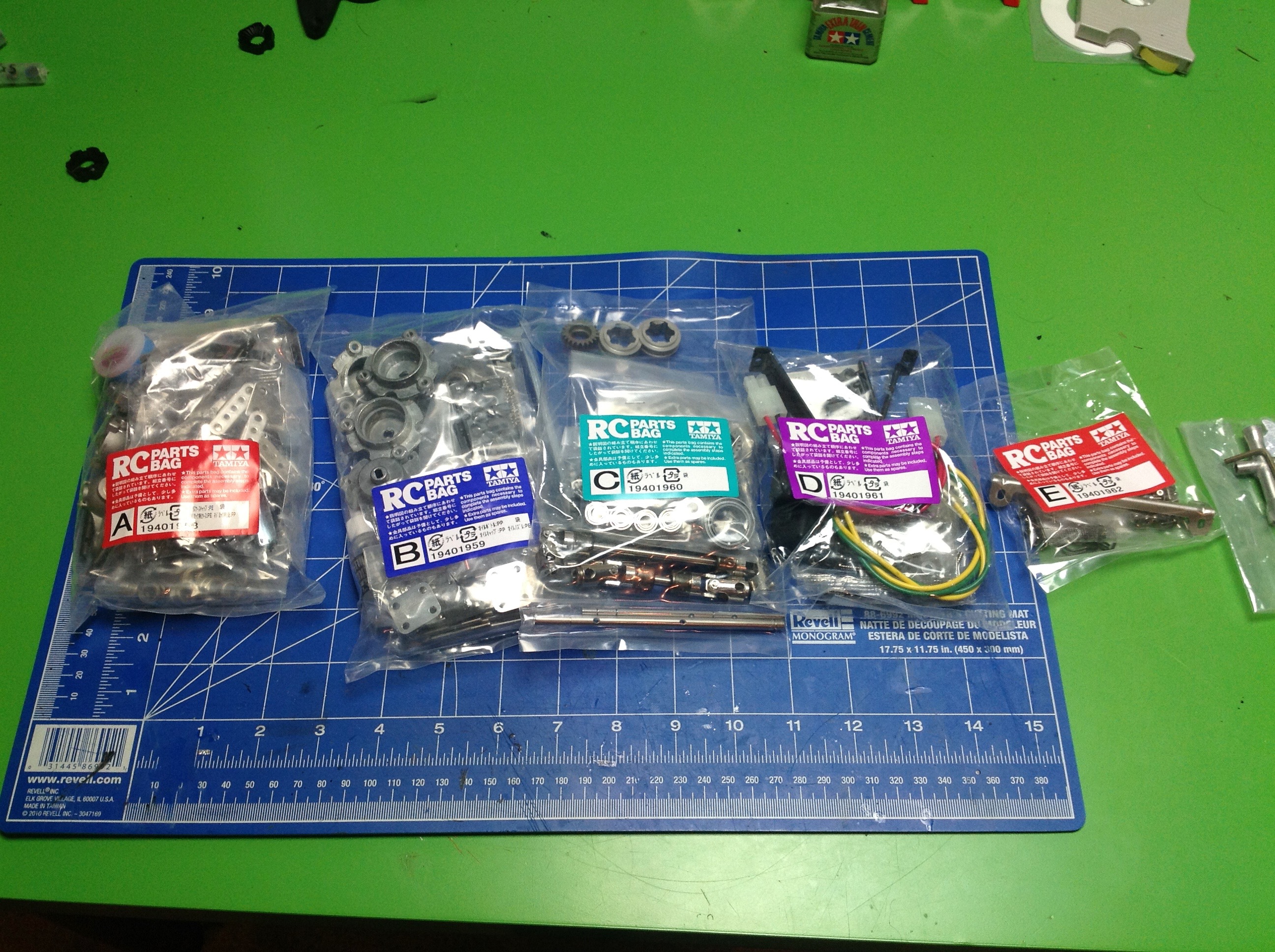
There is a lot of hardware inside. There are 5 bags labelled A-E
which contain the bulk of the fasteners and loose metal parts.
Others are contained in a blister pack in the box. I emptied the
hardware from each bag into a separate slot in my plastic case so I
could access everything more easily. The huge pile of metal
bushings you see are actually from the King Hauler, not from this
model. The Bruiser comes with full ball bearings.
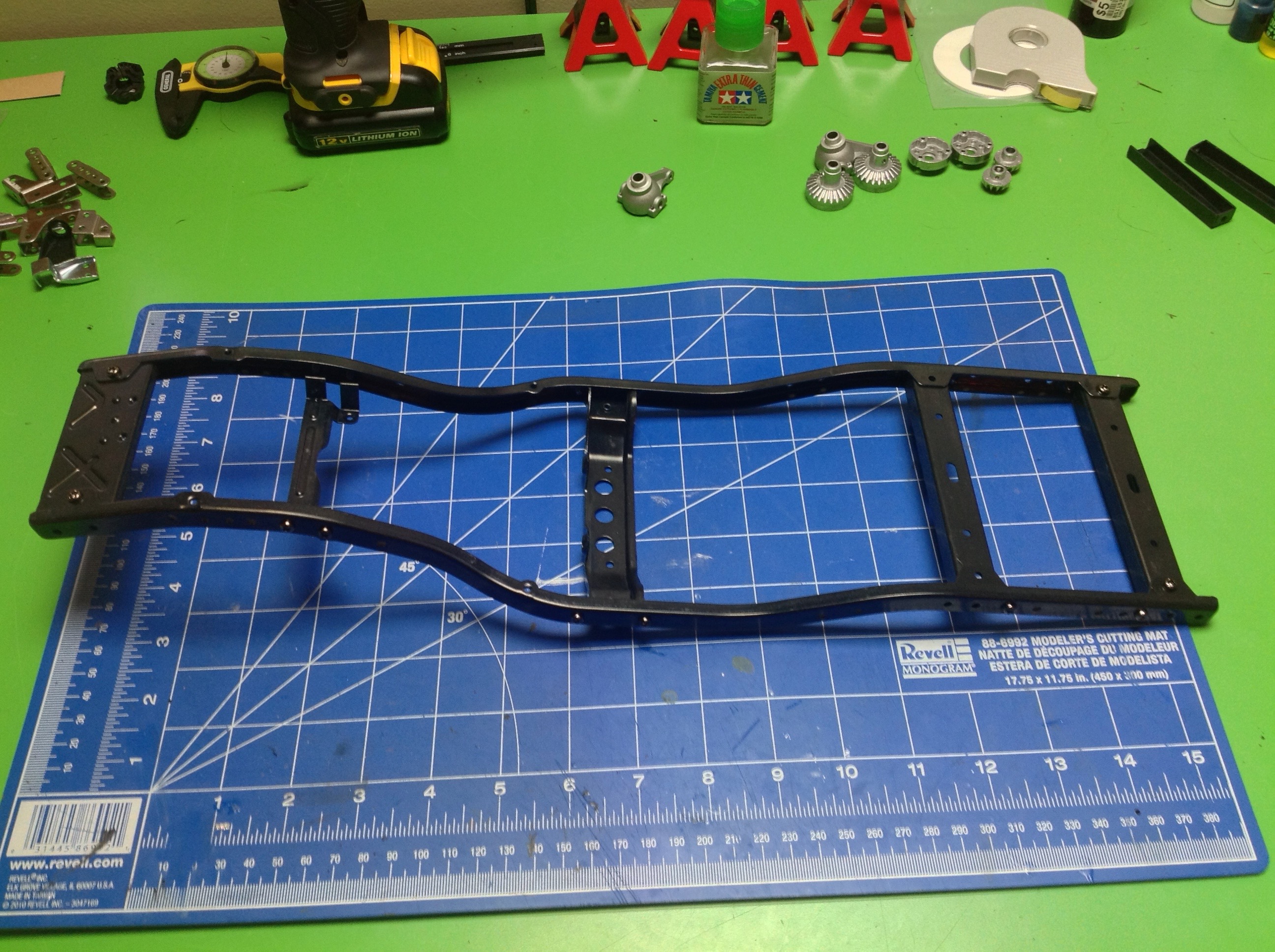
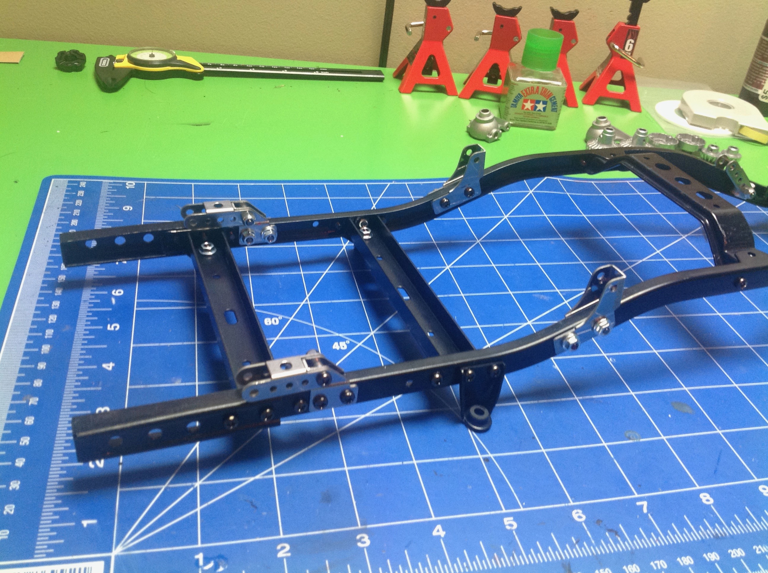
Step 1 starts right out with the frame rails and connects them will all
metal cross members. Since virtually this entire kit is metal,
using thread lock is very important. The kit includes some red gel
type thread lock, enough to do the whole model. It works a little
differently than regular blue liquid thread lock, but is actually
easier to apply in my opinion. The second step starts adding
brackets for the upper shock mounts.
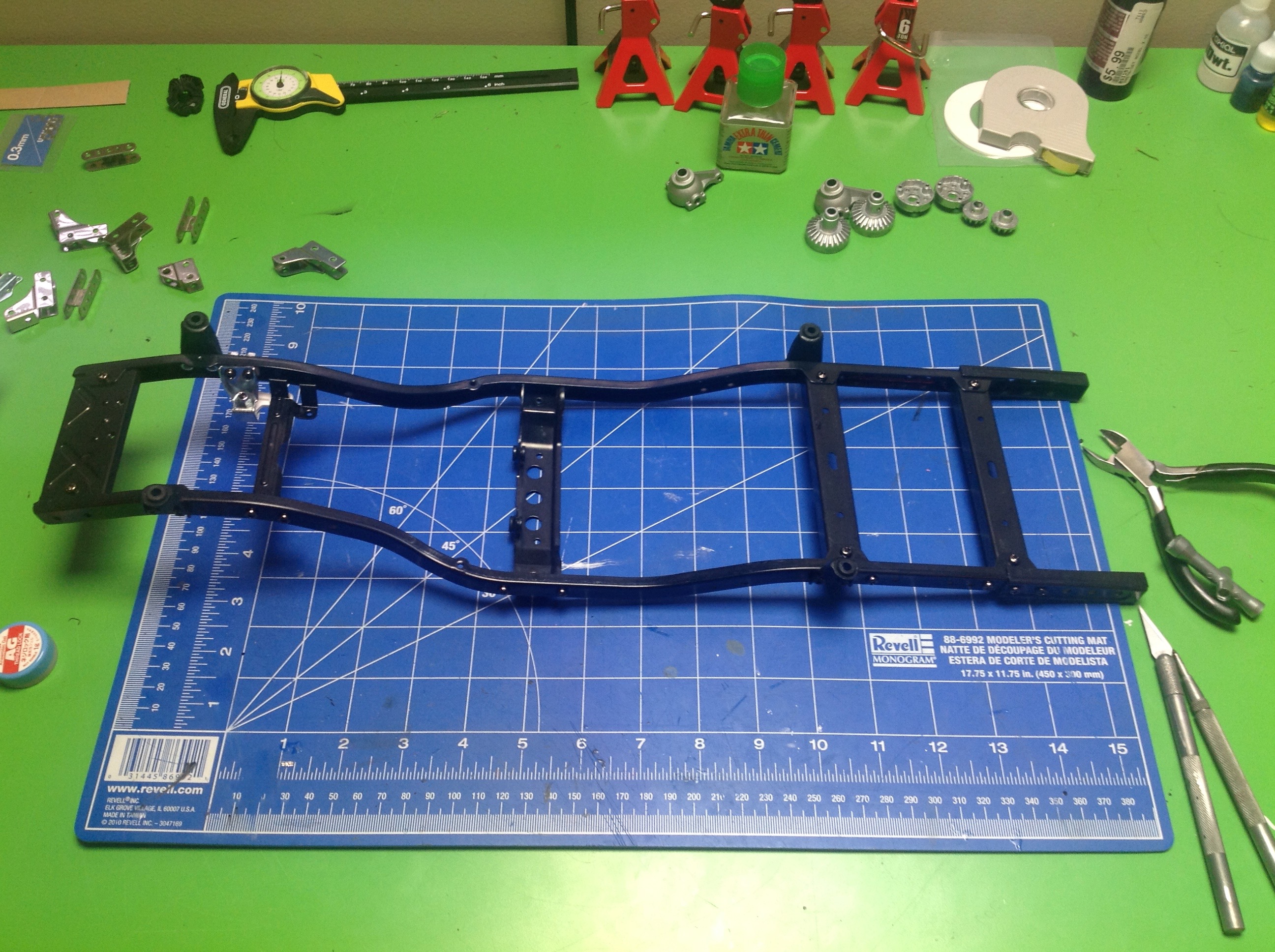
Steps 3 and 4 add shackles for the leaf springs and a crank arm for the
steering. At this point the only plastic part is that white
steering crank. Keep that in mind for later, because it is really
the only weak link on the model and is not nearly stiff enough to
properly control the steering. It is made from the same very soft
frangible plastic as the bumpers (and the other white parts). You
can see the rubber grommets at the top of the damper stays which will
cushion impacts. This model is full of little details like that.
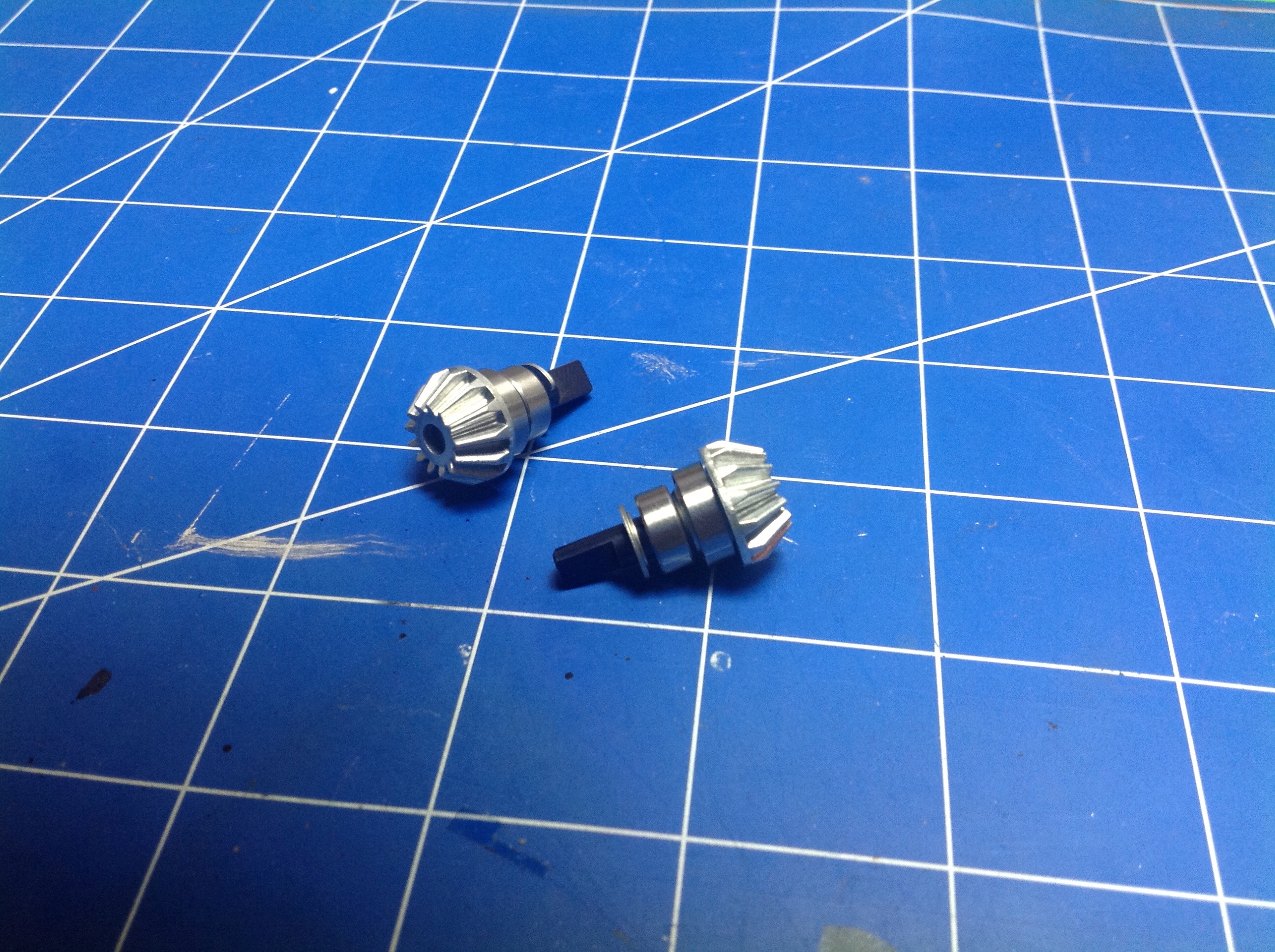
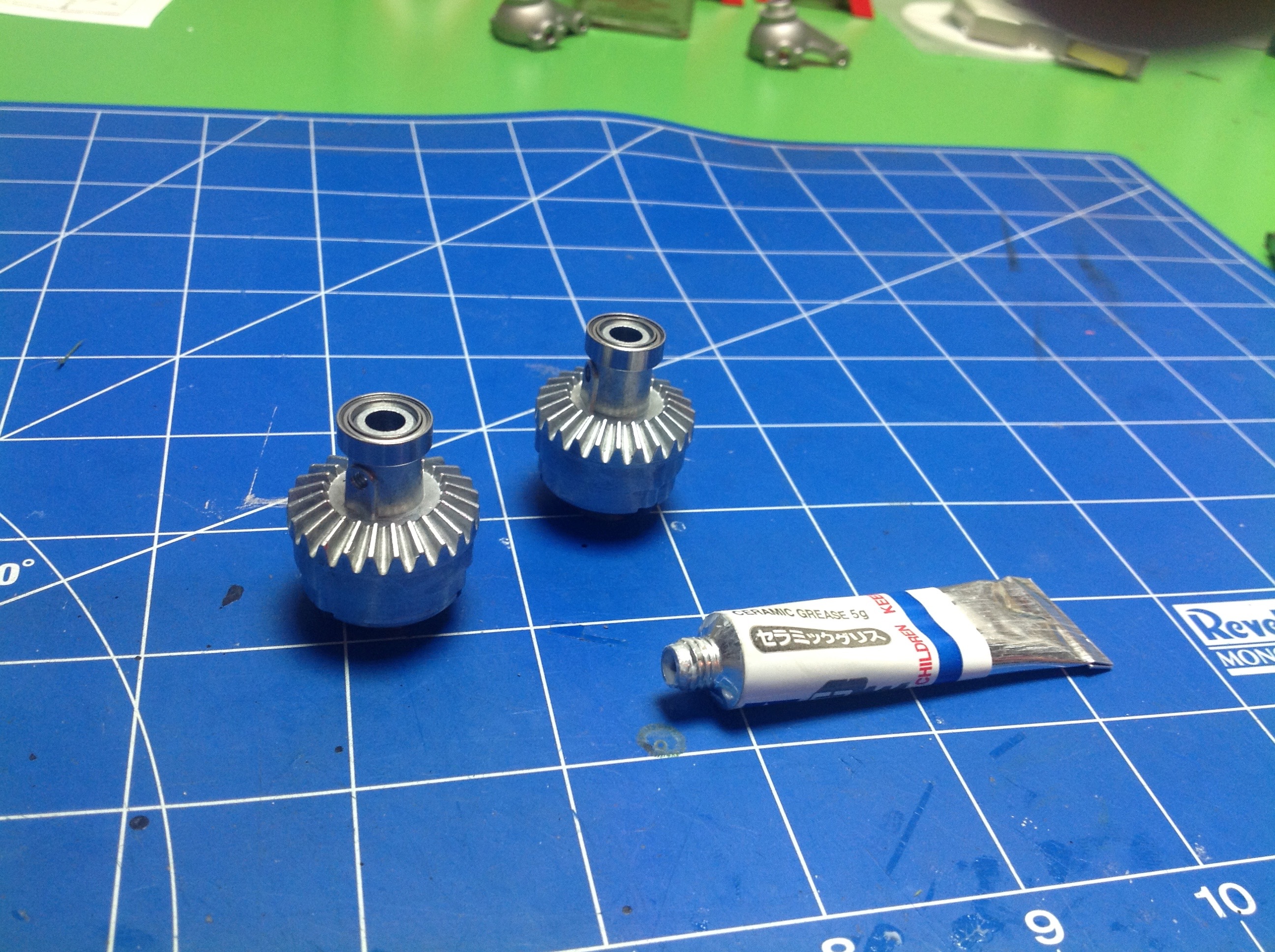
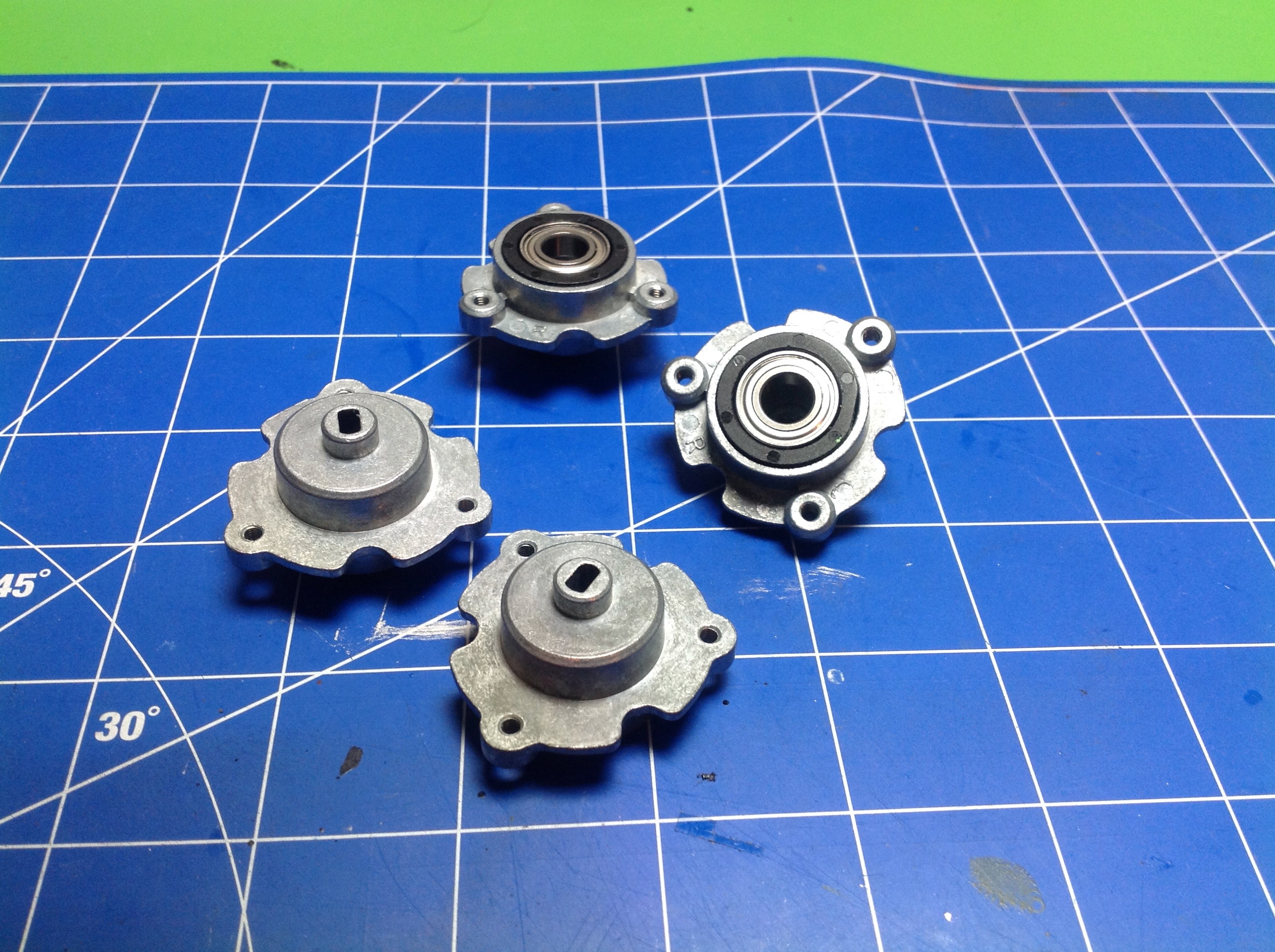
Time to build the differentials. Step 5 attaches bearings and stub
axles to the 13 tooth metal pinion gears. The gears appear to be cast
alloy rather than machined which makes them weaker than they could be
but still stronger than plastic.
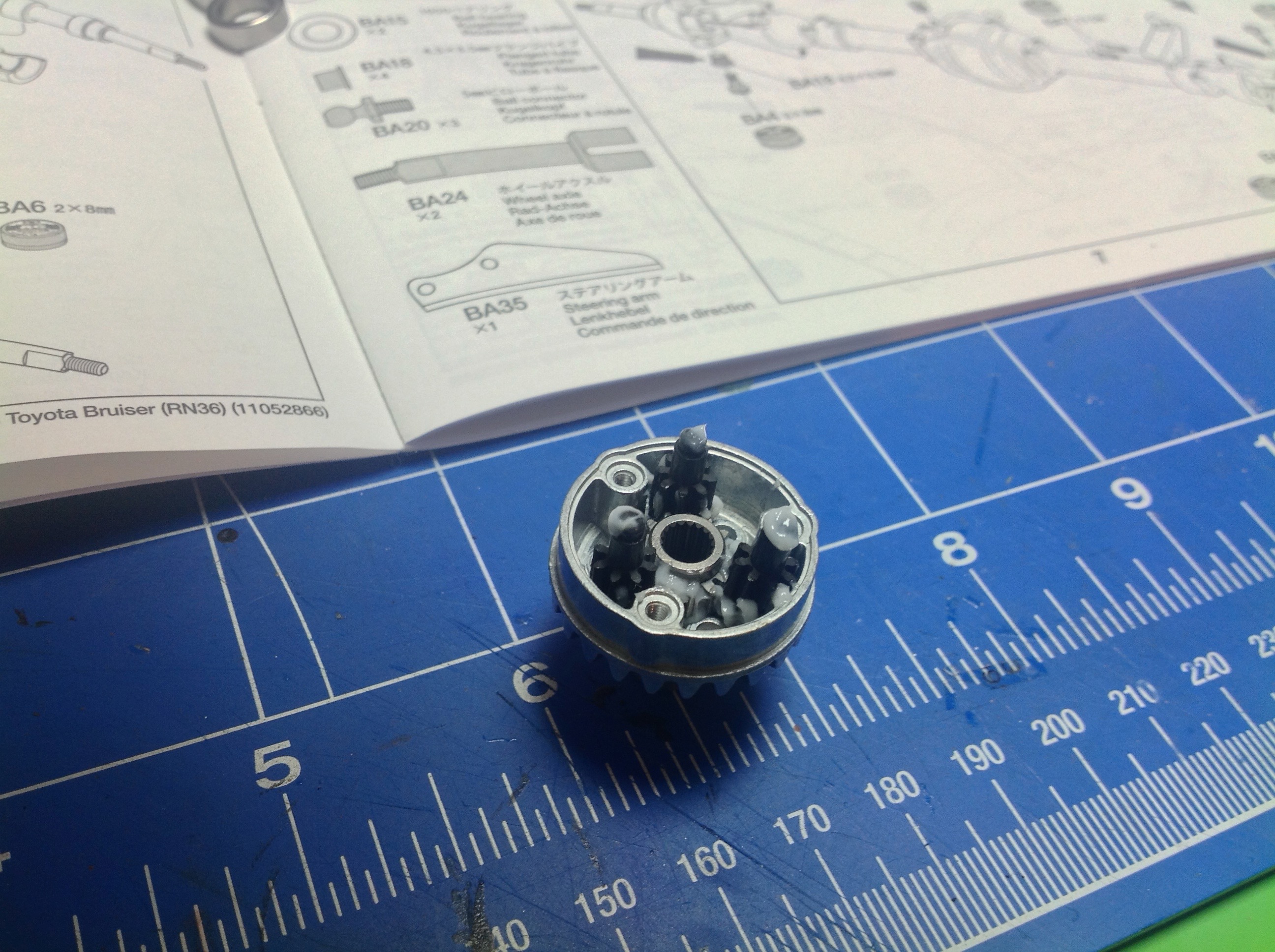
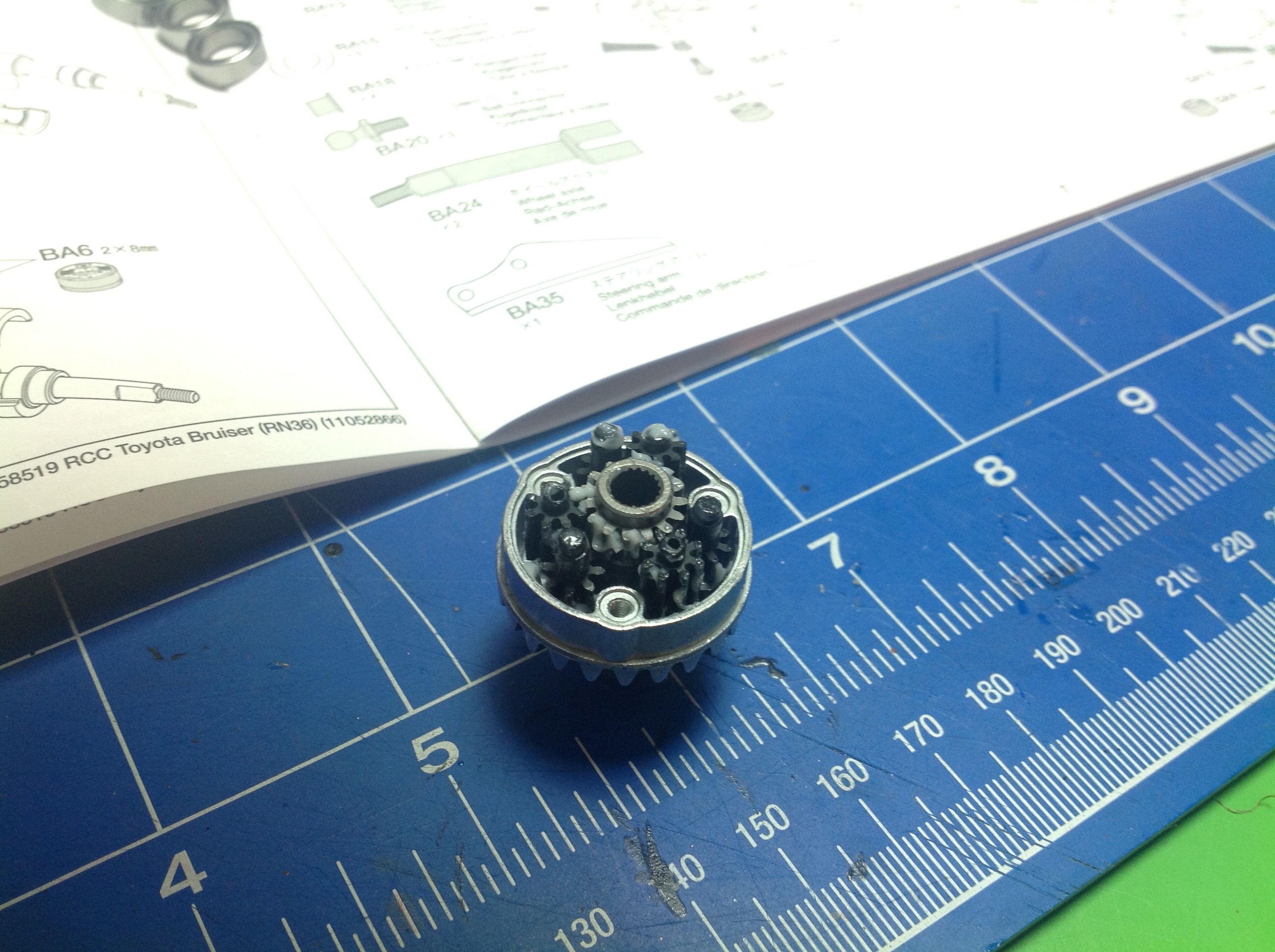
The model uses gear differentials, but not your standard bevel gear
type. These are planetary differentials using only spur
gears. The left picture shows the first layer which is an output
sun mating with 3 planets. The planet axles are locked to the
housing making it the planet carrier. The right hand picture shows
the second layer which is another set of planets and the opposite side
sun gear. The two layers of planet gears mesh together to rotate opposite directions.
The 24 tooth ring gears are integral to the housings. When the
housing
spins, the planet carriers follow along. As long as no wheels are
slipping, the planets do not rotate. If one wheel slips, the orbit
of the planets allows the sun gears, which output to the axles, to spin
independently. Awesome system. The original Bruiser
actually had no differentials at all, it just used locked spools.
This is one of the two primary differences between the re-re and the
original, the other being the gearbox.
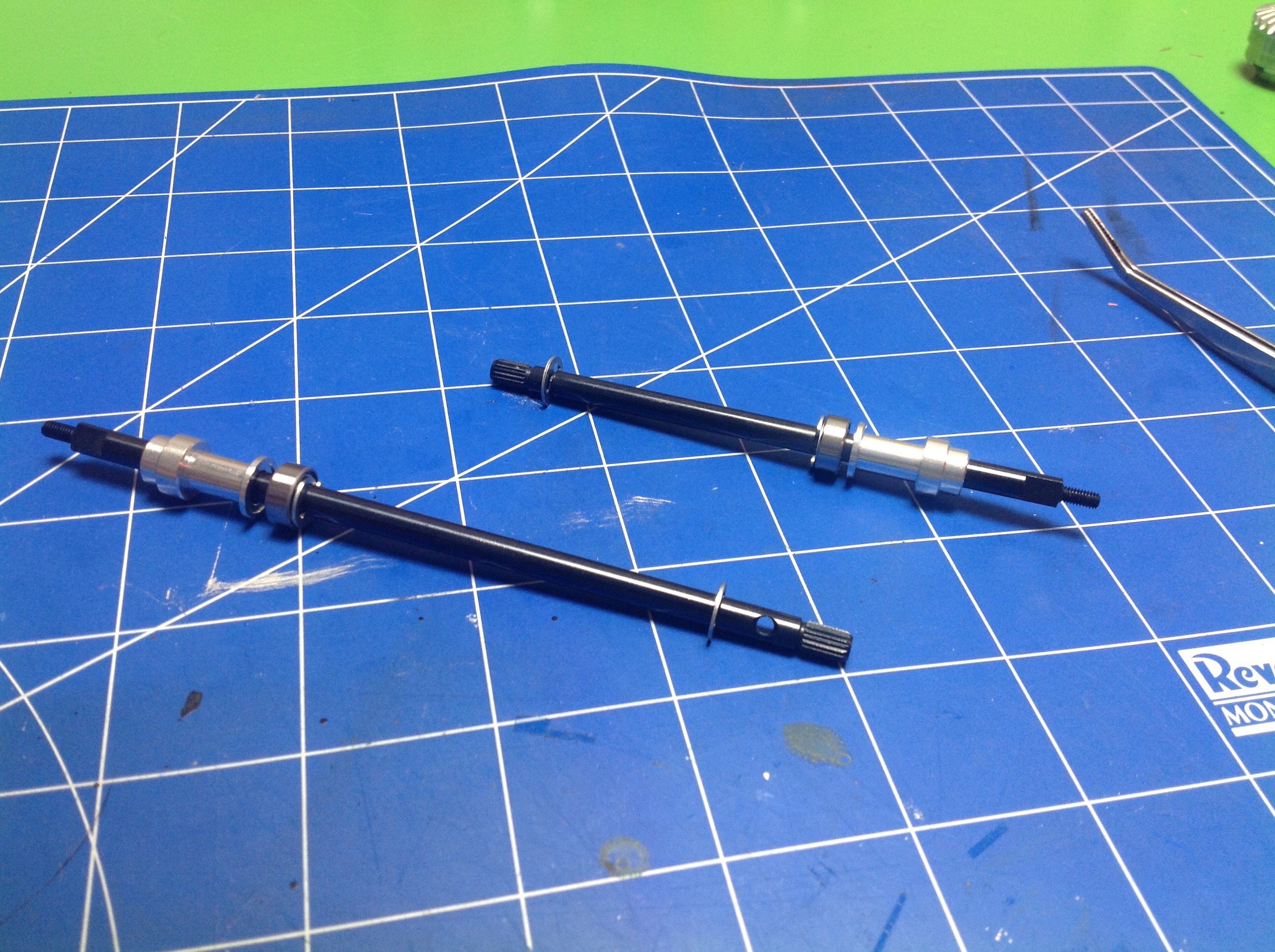
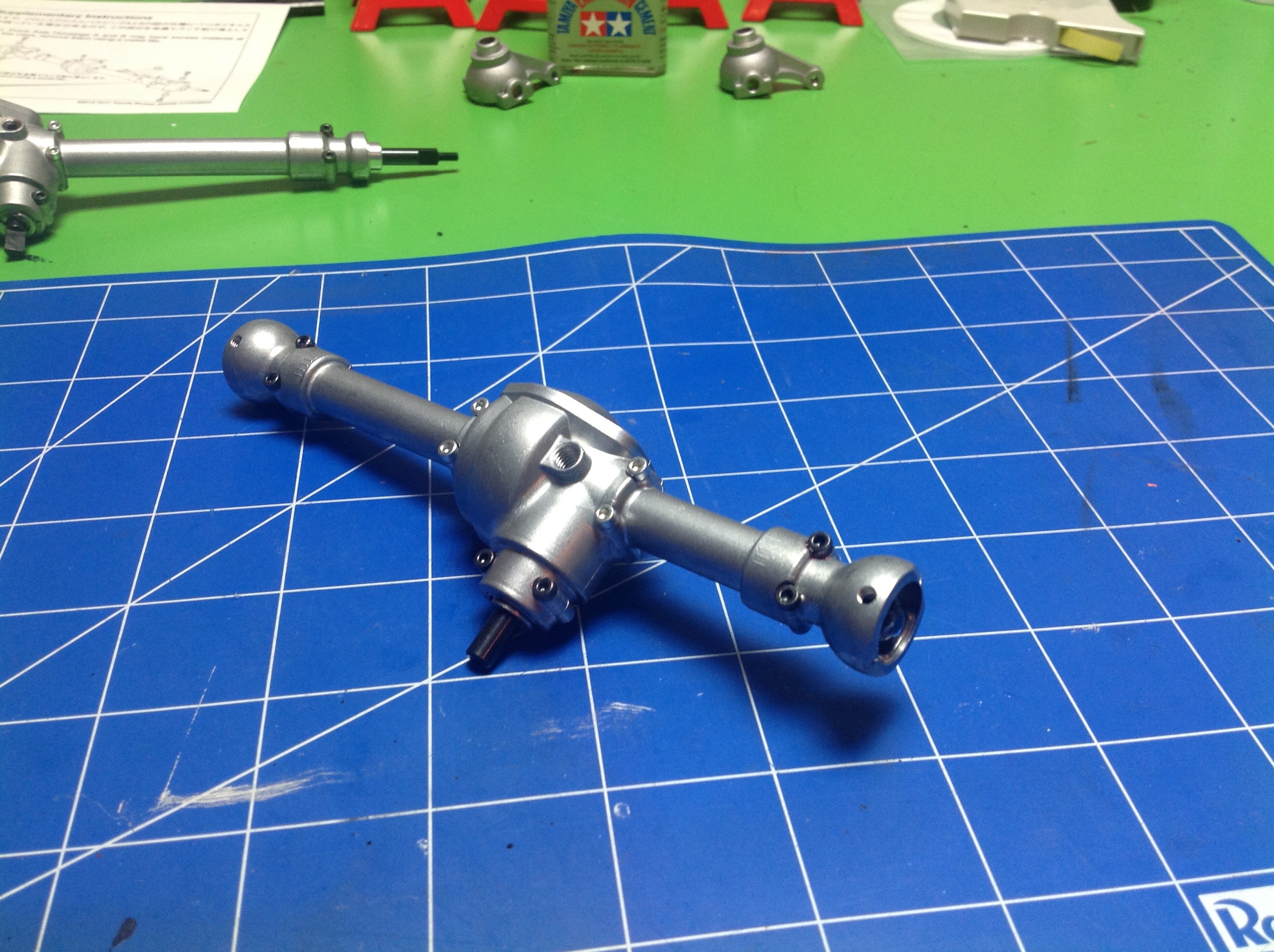
Now the rear axle. We start with a pair of splined steel shafts
and add some aluminum support collars, ball bearings, and E-clips.
The axle housing is cast aluminum as well and holds the axles,
differential, and pinion. I was a little worried about how thin
the wall of the axle housing is, but it has been no problem at
all. Just make sure not to over tighten the screws.
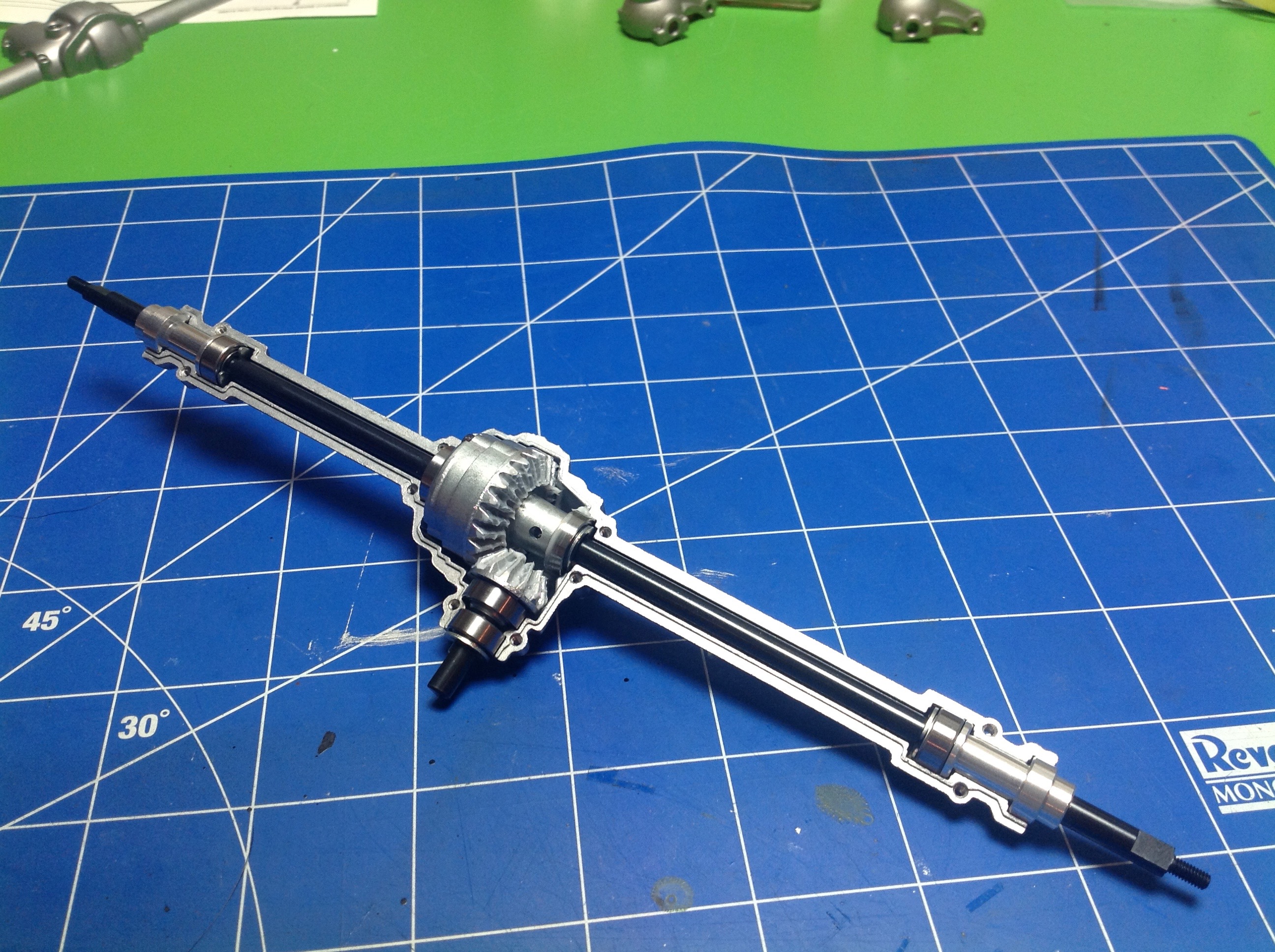
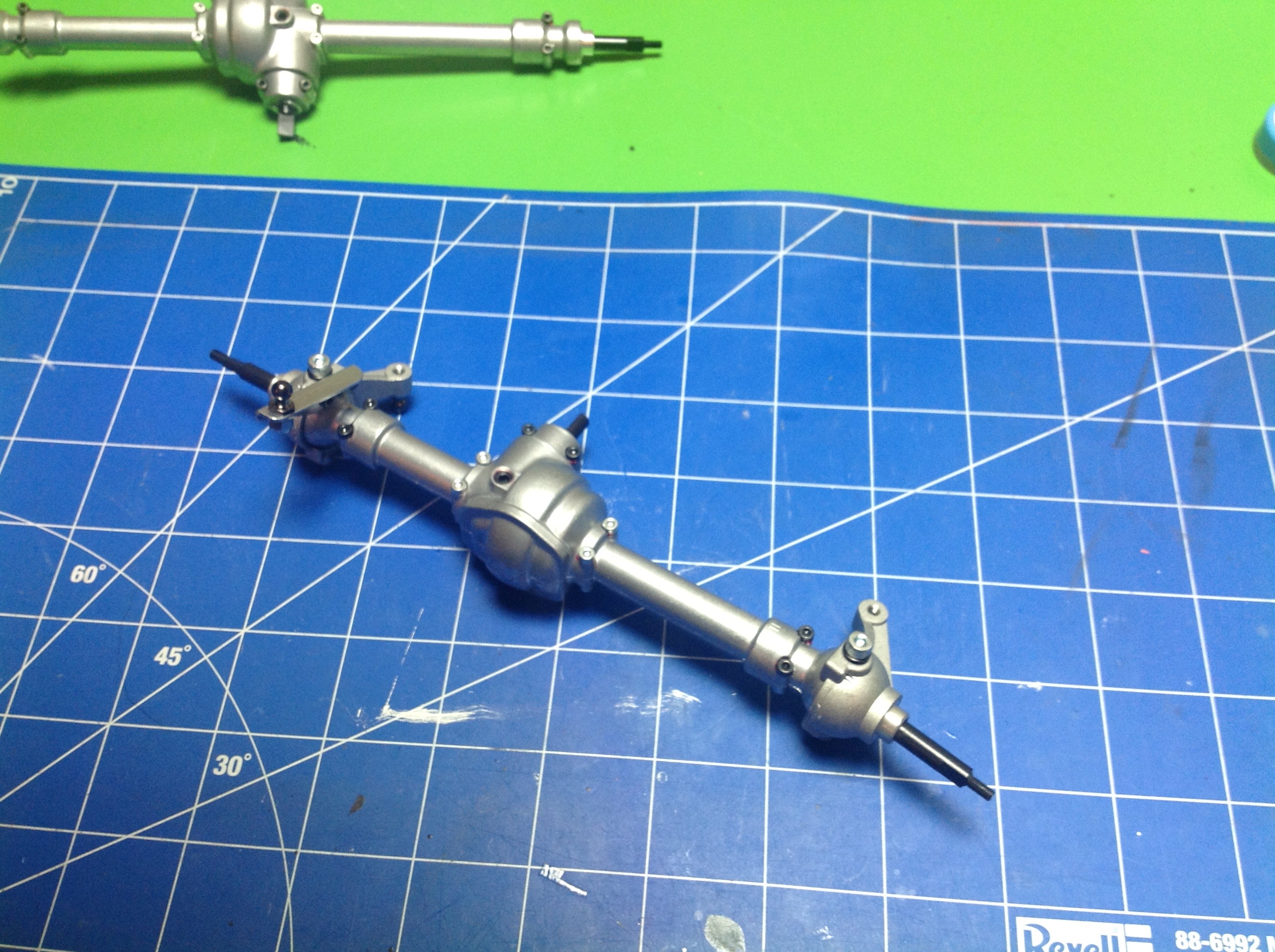
The front axle is a bit different because it has to steer. The
basic construction of the internals is the same, but instead of ending
in splined shafts the axles end in dog bones beneath a spherical
hub. The second image shows the steering knuckles and output stub
axles installed. In both images you can see an open hole above the
differential. This is an access point to install a grub screw
which locks the differential. It is really nice that you can lock
and unlock the diffs, however this hole faces upward and is therefore
not accessible once the axle assemblies are mounted, so it is best to
decide now which way you want to go. I started by leaving the
diffs unlocked but found once I finished that the off road traction was
poor so I went back and locked them. Then I found that the
steering was poor. As a compromise, I went back the third time and
used Tamiya anti-wear grease to semi-lock them and I think that is the best choice.
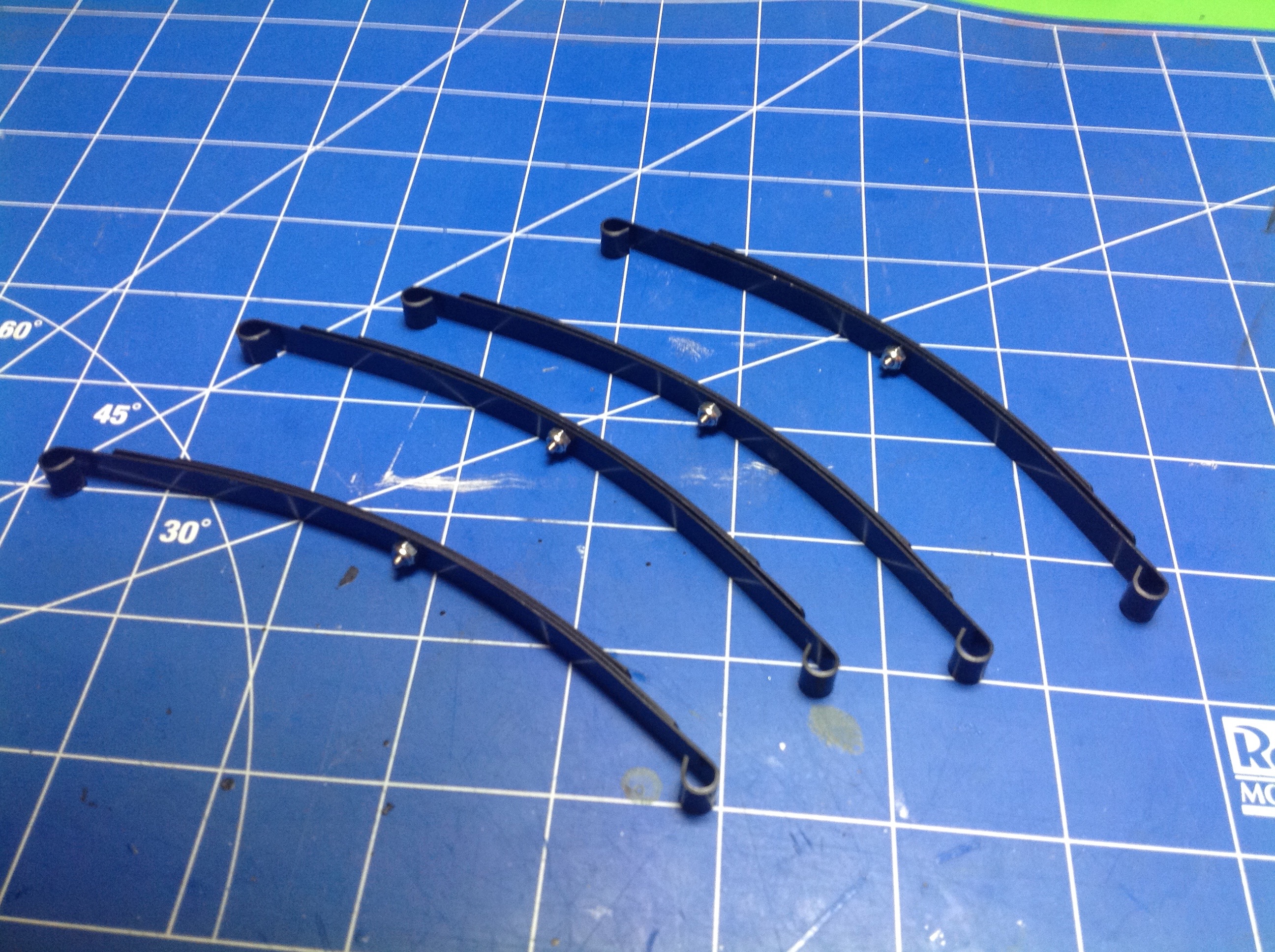
Step 10 opens hardware bag B and begins assembly of the
suspension. We start with the leaf springs, each of which uses 3
stacked leaves. Nothing makes a better scale truck than real metal
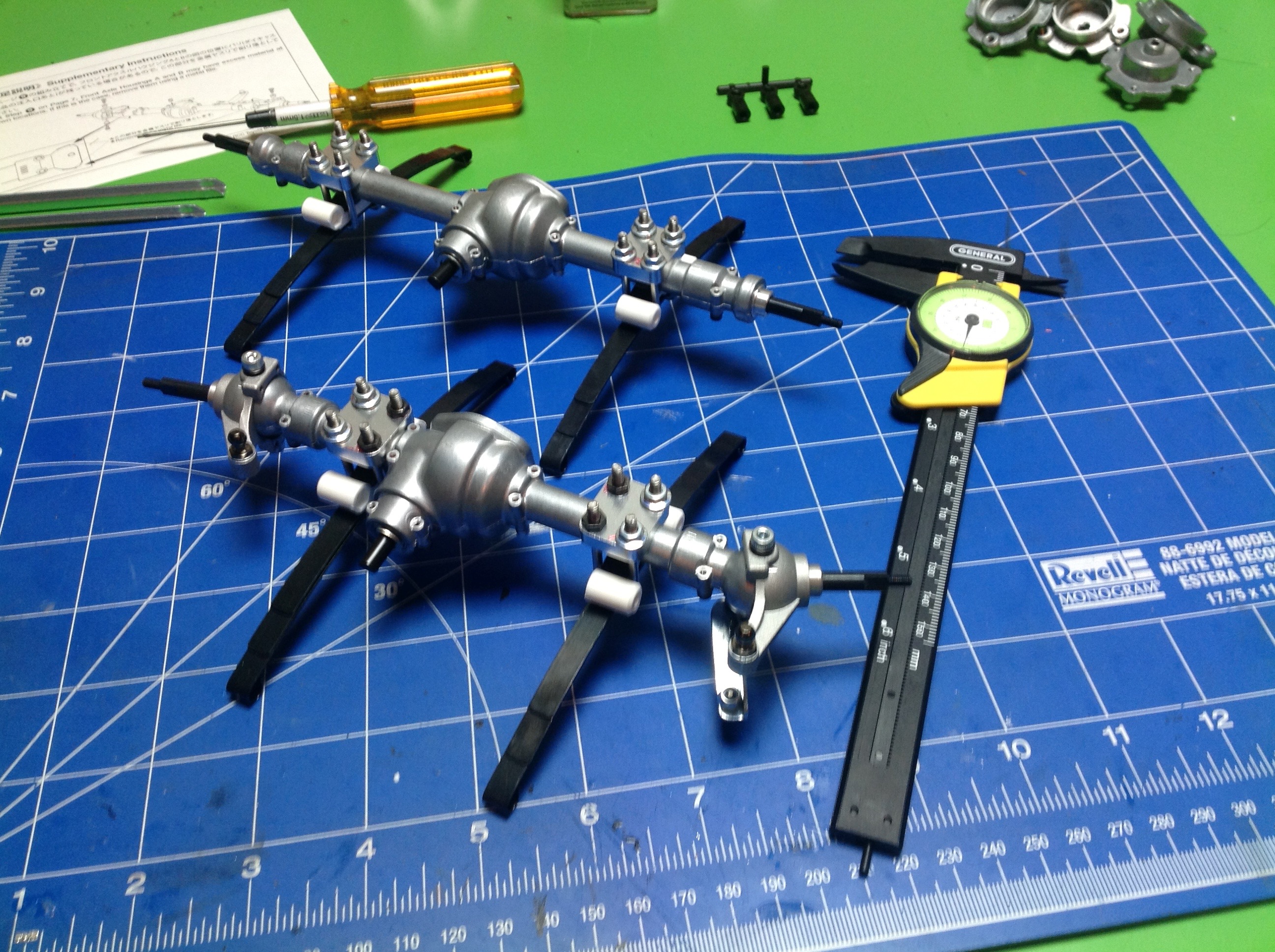
leaf springs. Next the springs are connected to the axles.
This is actually a bit tricky because the axle housings can rotate in
the saddle clamps until everything is tightened. You need to get
them oriented correctly so the inputs will face the right direction to
accept the drive shafts. The angles are shown in the instructions,
but you have to eyeball them and then try to hold everything in place
while you tighten. The manual says to use "synthetic rubber
cement" here. I didn't know what that meant so I used CA which was
a problem because then nothing can be adjusted. Turns out that
you can use Shoe-Goo which I highly recommend. This will stay
pliable so you can make adjustments. This step also adds only the
second set of plastic parts which are the shock mounts. You can
buy metal versions
from RC4WD and if I were doing it again I would probably get them but
they are difficult to retrofit because you have to do all the
adjustments again. To be fair, I've had no problem with the
plastic. Metal is just cooler. If you don't understand why
then you shouldn't buy this kit.
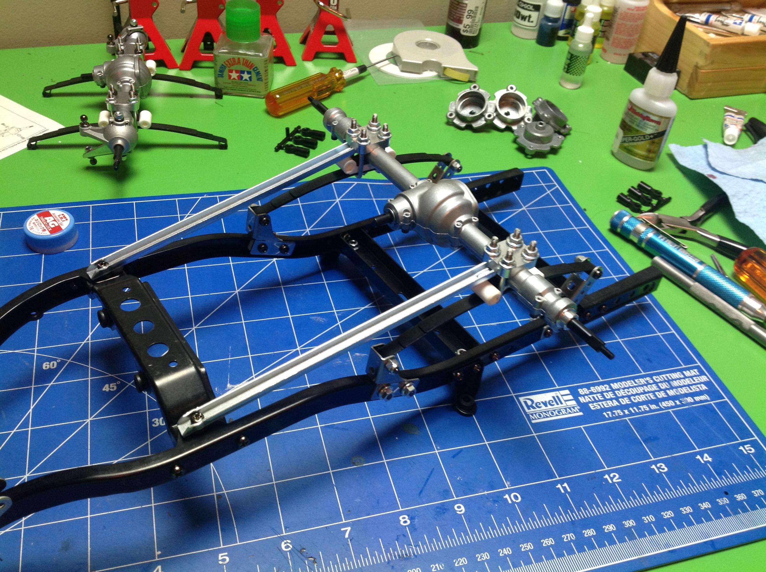
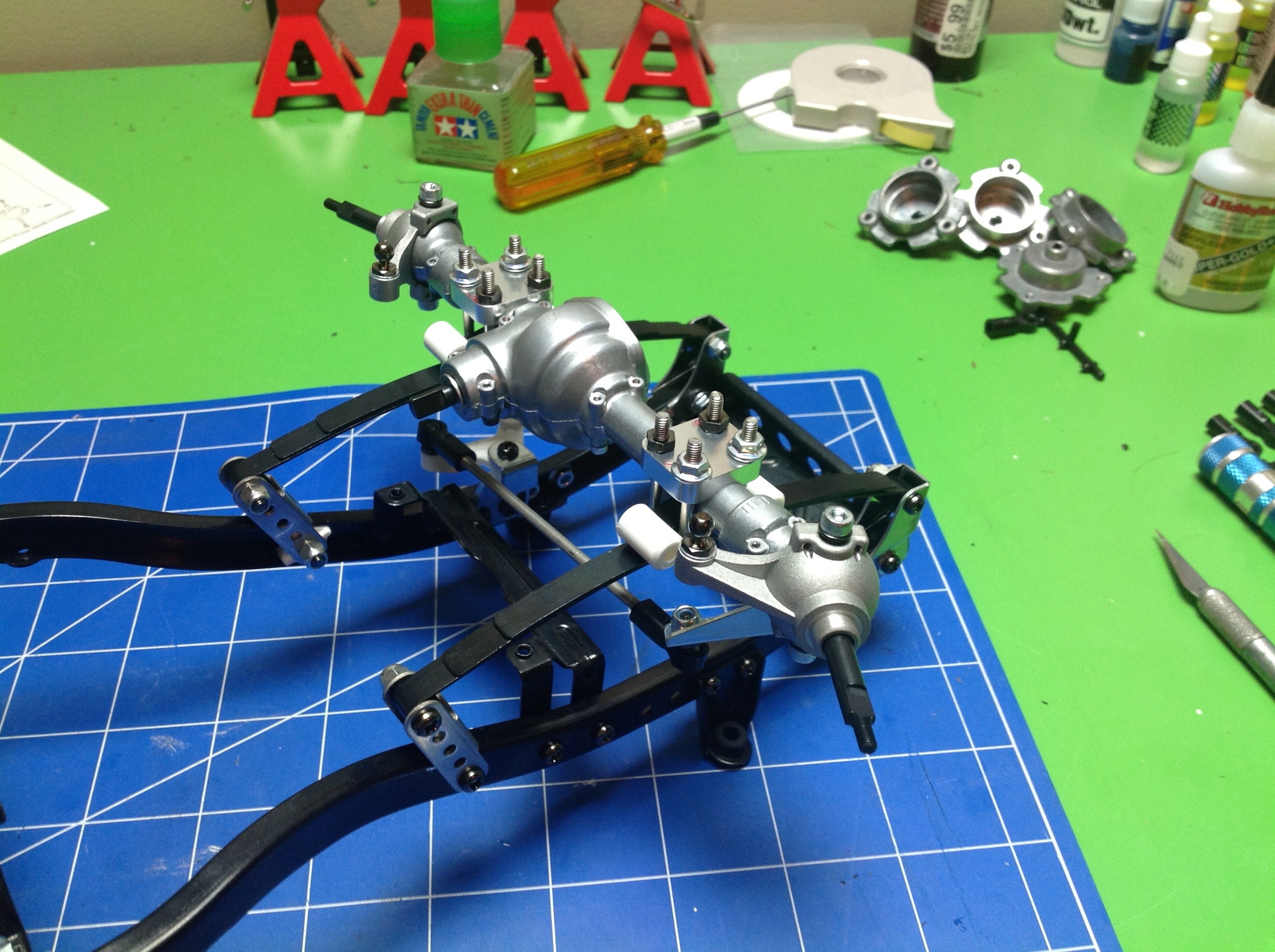
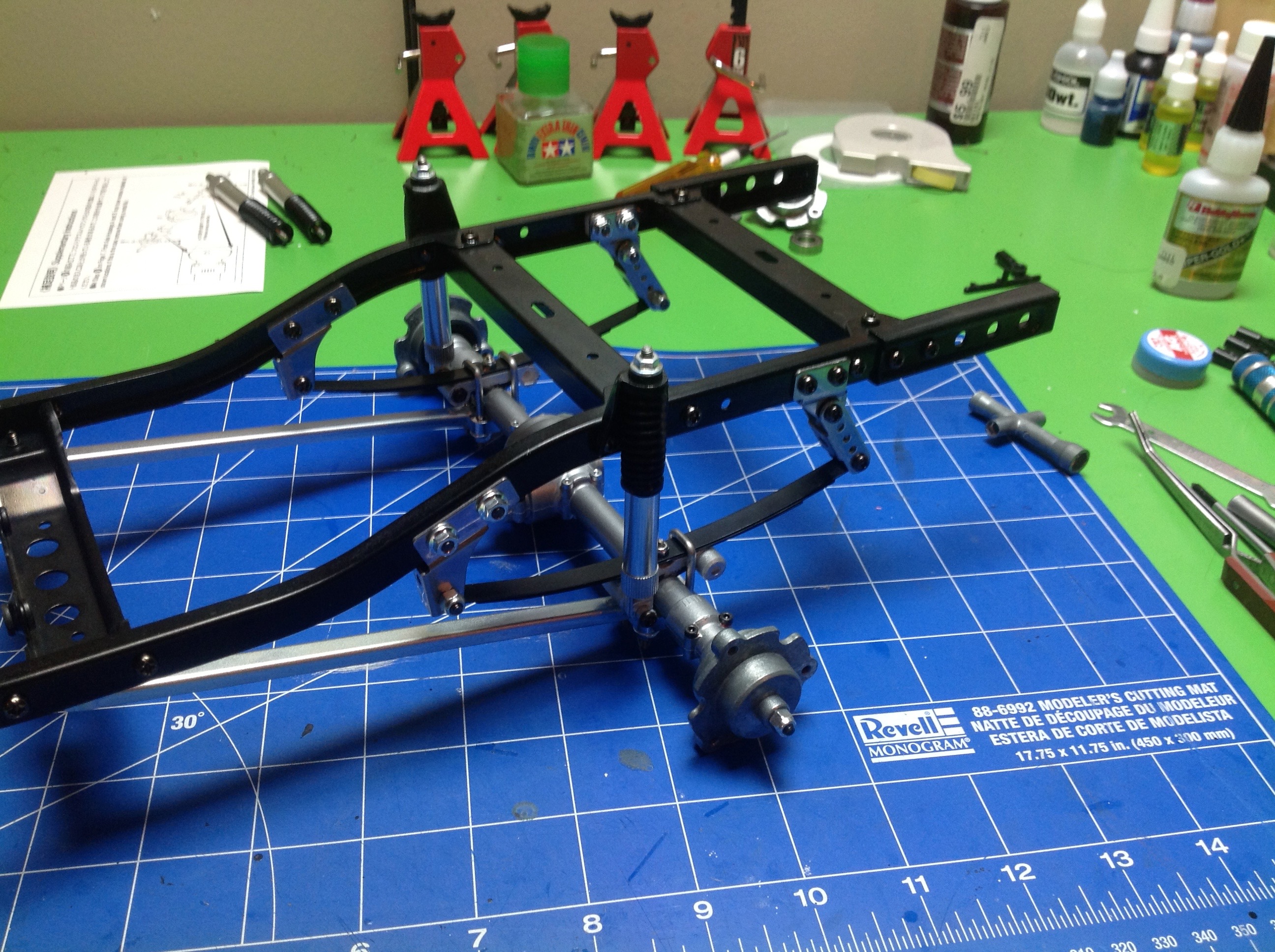
Now it is time to install the axles on the frame and make this look like
a chassis. The rear suspension uses a pair of long trailing arms
to stabilize the leaf springs and carry thrust loads. The front
axle just bolts directly to the springs. There is no panhard rod,
so steering forces get transmitted to the springs.
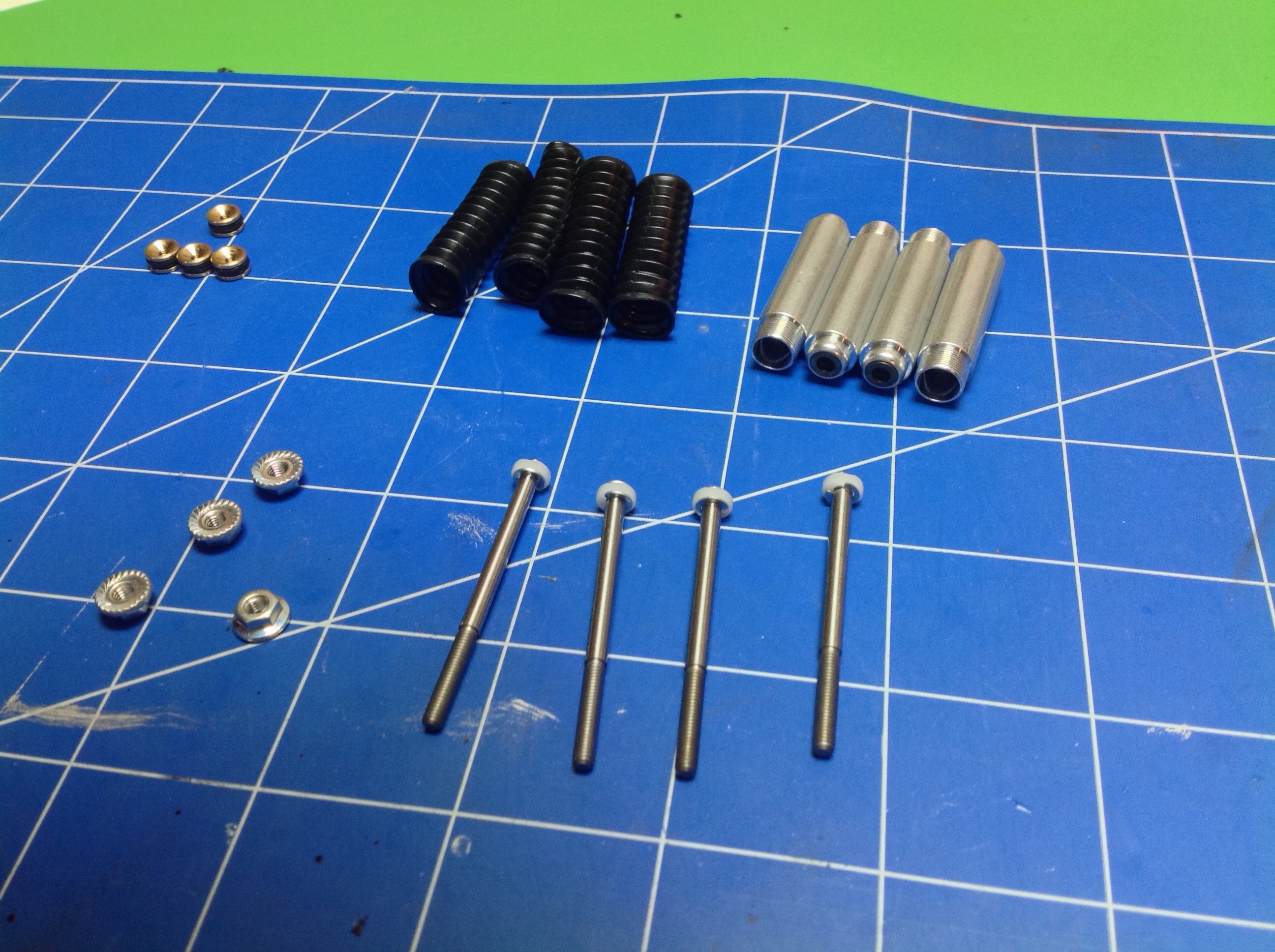
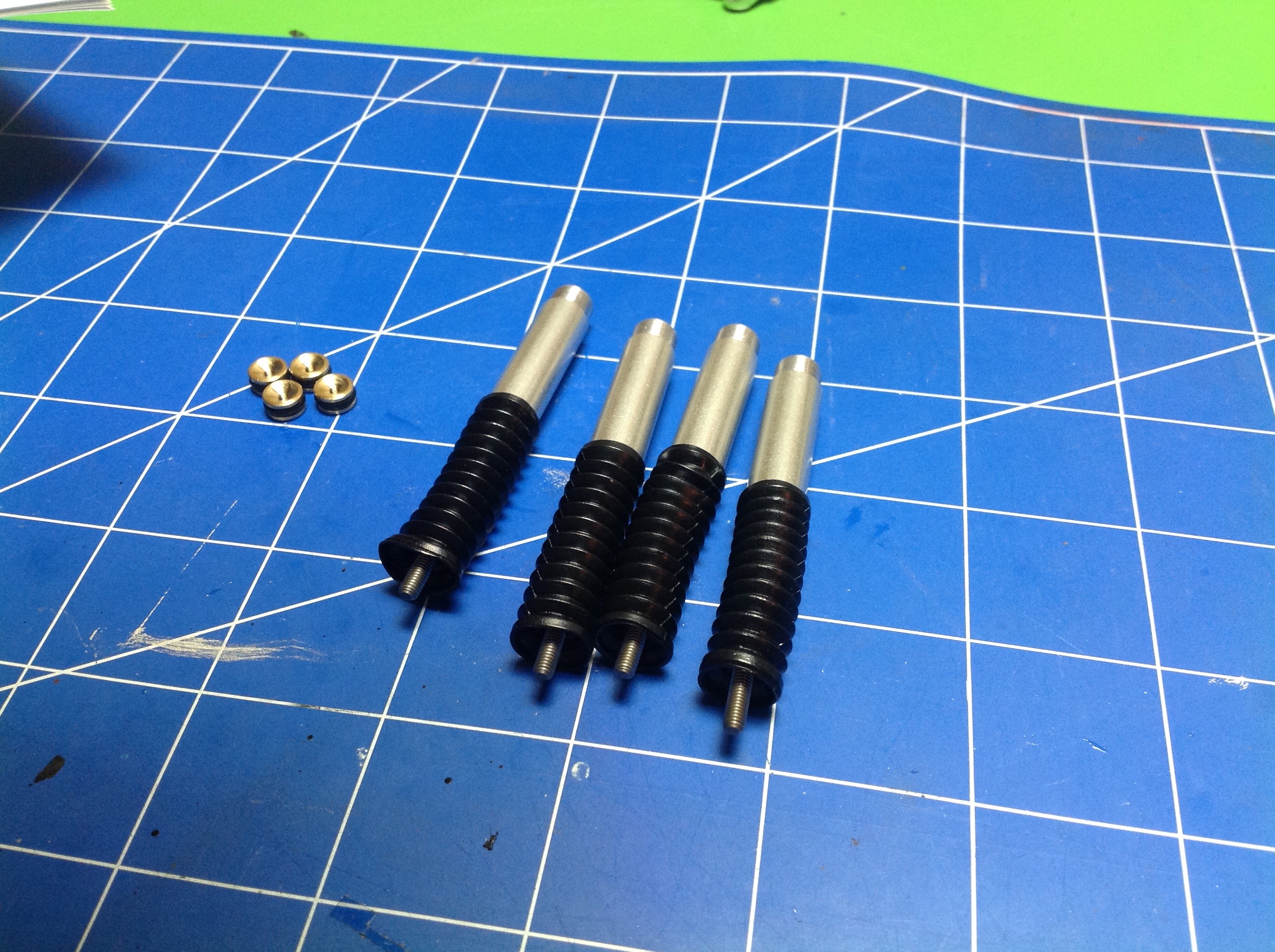
The shock absorbers are quite unusual. They are oil filled, but
they are not sprung. They act only as dampers for the leaf
springs. The main piston does not have any holes in it, instead is
has flat spots on the side to allow for fluid passage. The piston
is retained with E-clips. After filling the shock, you add a
second floating piston which has an o-ring seal. This replaces a
bladder for volume compensation and floats up and down with shock
stroke. There's a nice rubber boot which protects the main rod
seals from contamination.
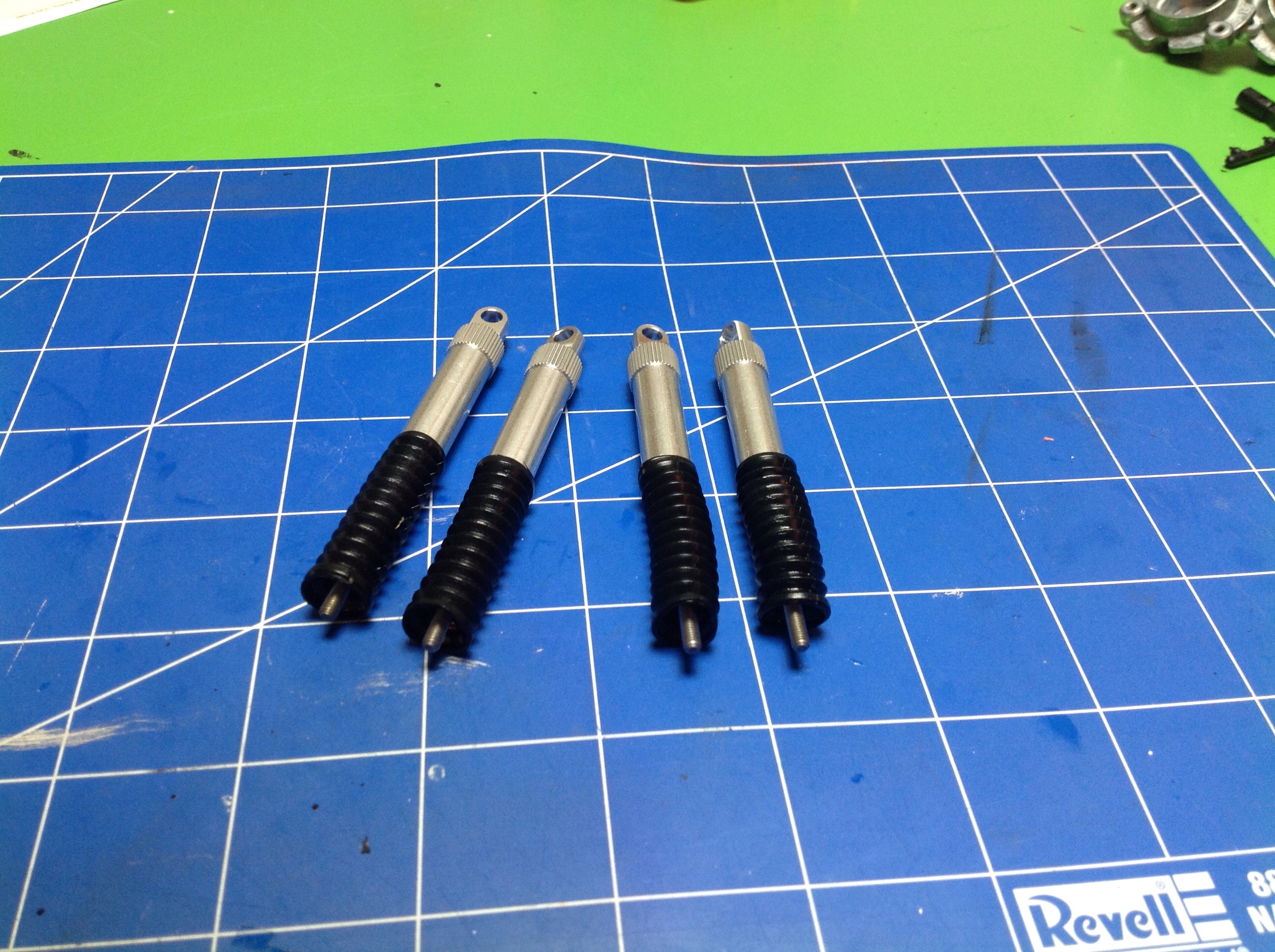
Once the head ends are installed the shocks are complete. There
are no rod ends. The rod threads directly into the damper stays
on the chassis.
Step 15 builds the highly unusual wheel hubs.
No hexes here. The stub axles have flats which drive the hubs, and
the wheels actually bolt onto the hubs with 3 screws.
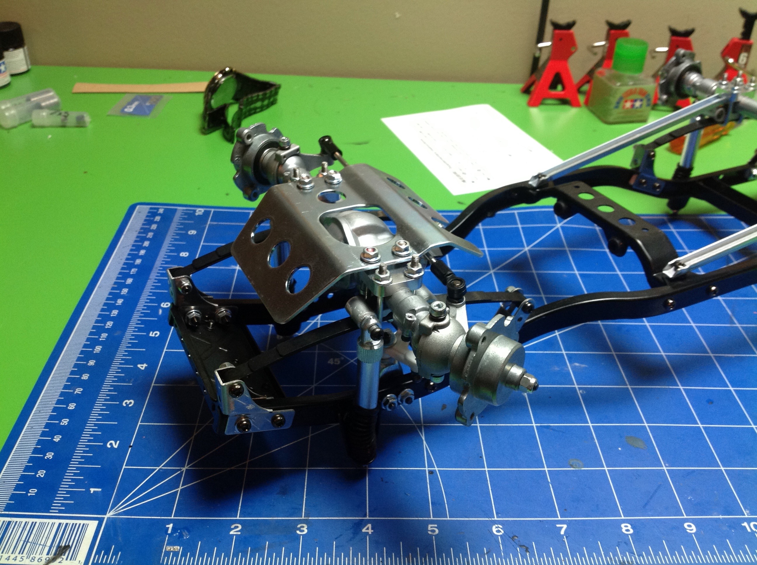
Now the dampers and wheel hubs are added to the chassis. Note the
unusual inverted damper arrangement and the lack of rod ends. The
left image shows the rear axle and the right image shows the front with protective skid plate.
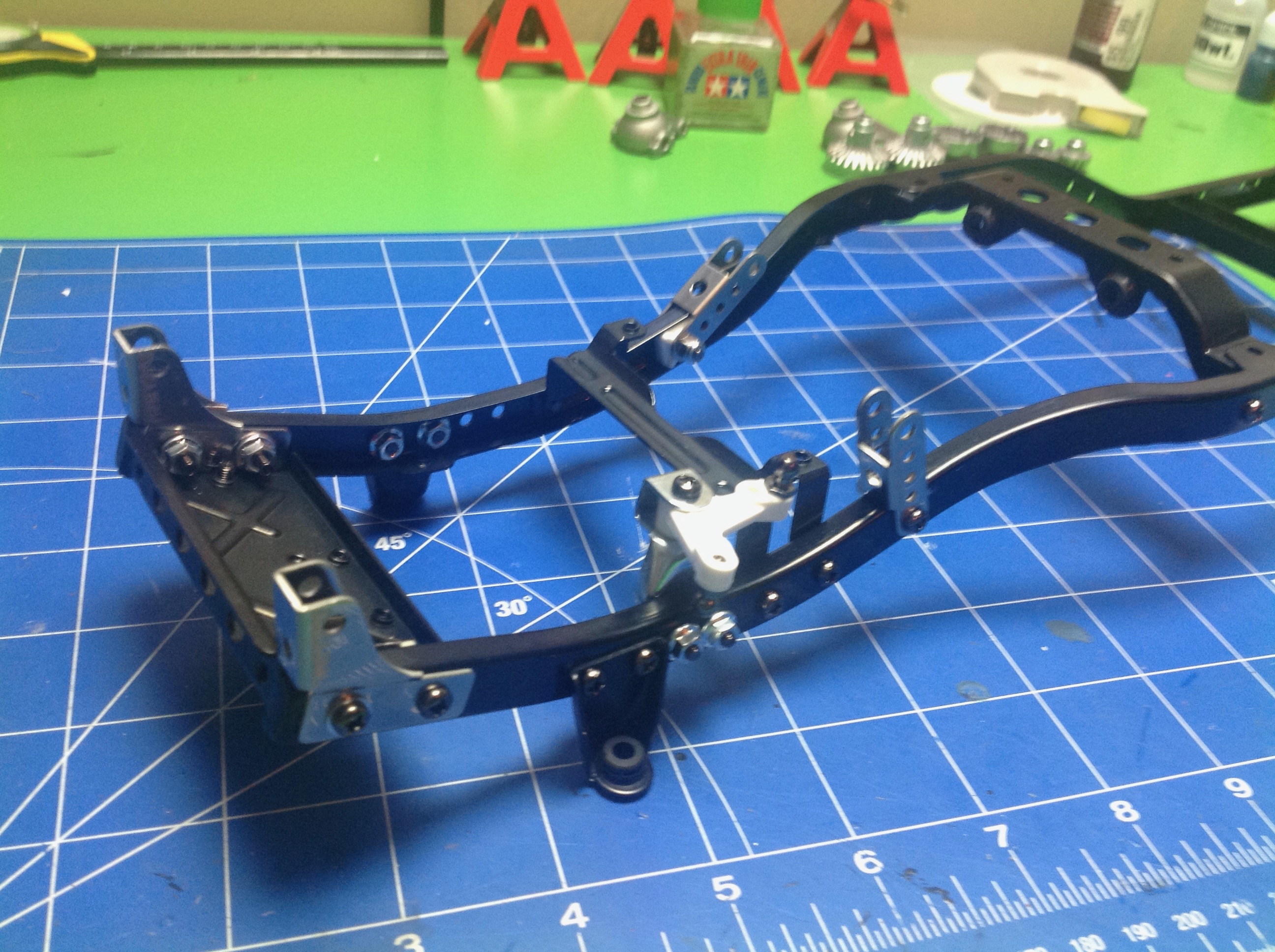
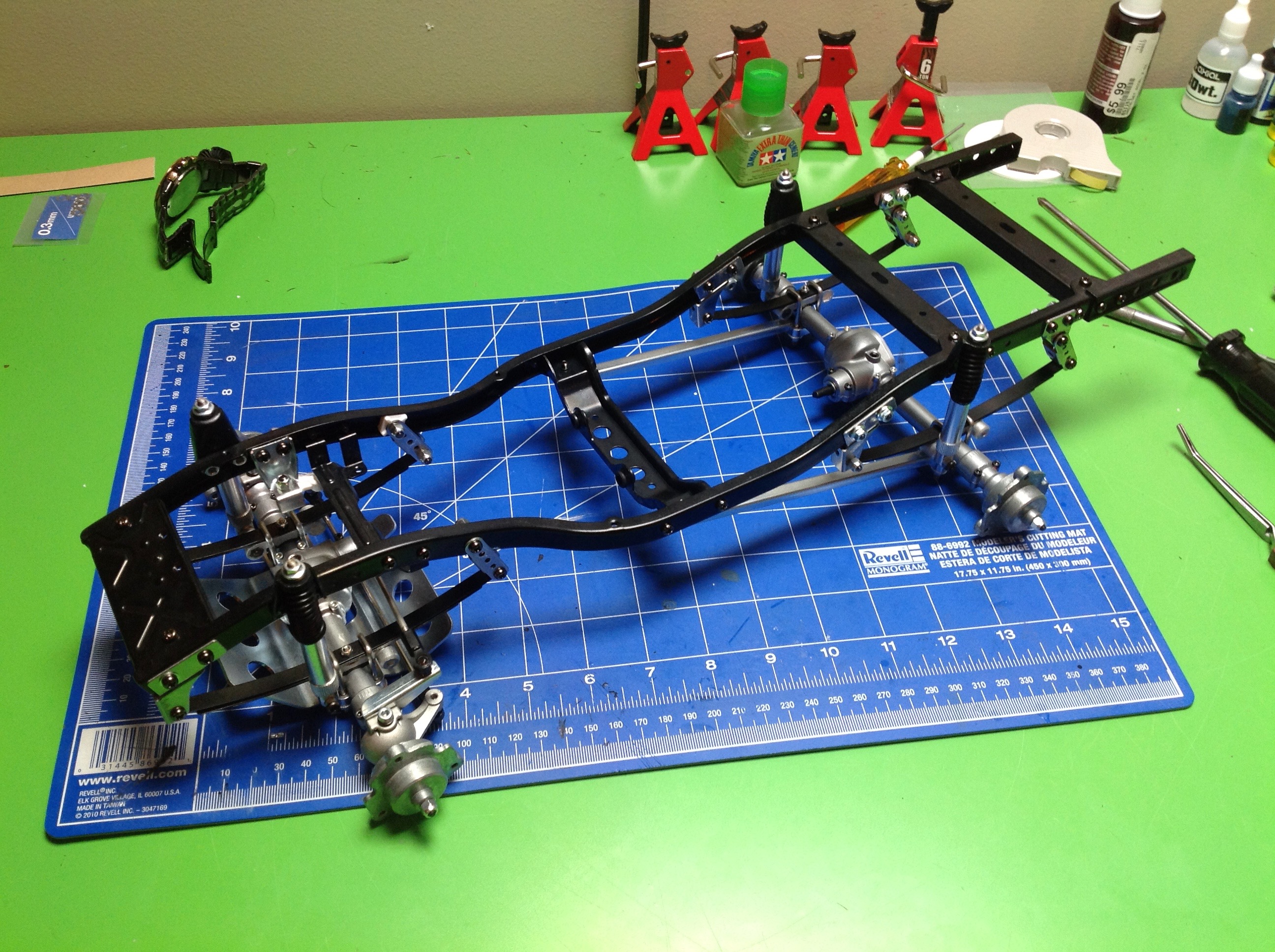
After Step 17 the rolling chassis is complete. Pretty much
everything you see here is metal and it is glorious. There are no
weak links here, you can grab it anywhere and shake it around and
everything stays well together.