Tamiya Bruiser Project
Page 2: Building the Transmission
The 3-speed transmission is a thing of great beauty. I expected
that it would be pretty much the same as the 3-speed in the King Hauler
(or other tractor trucks, or Highlift trucks which use essentially the
same transmission),
but that's not true at all. This is a completely unique beast,
and actually much more complicated than the King Hauler. The
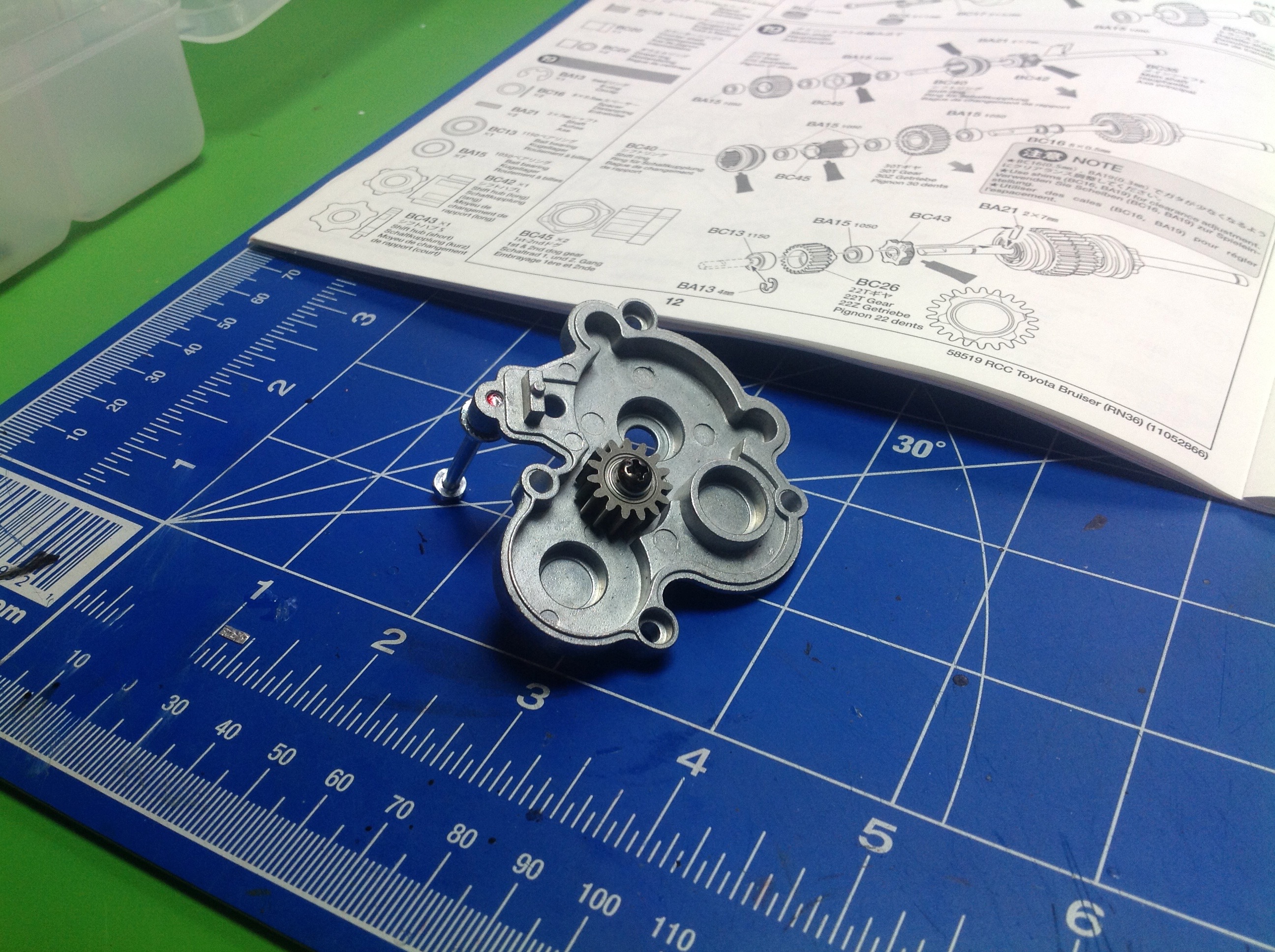
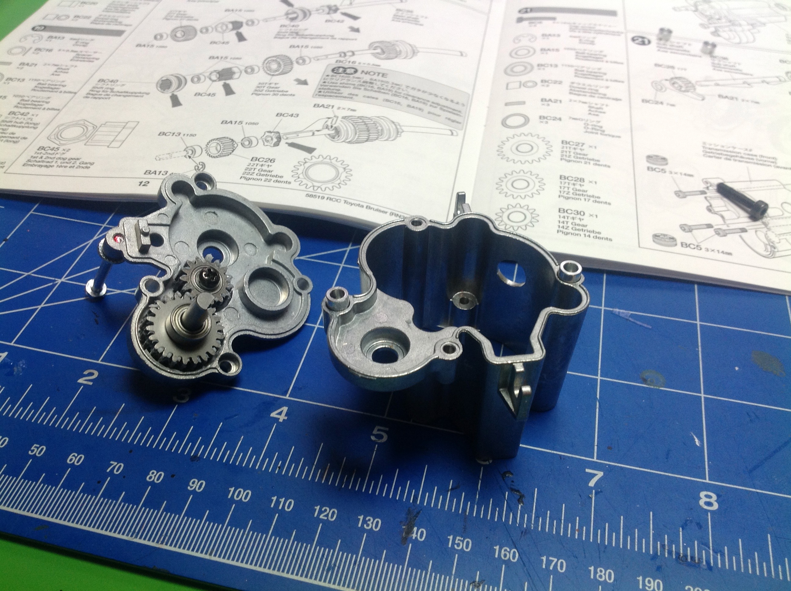
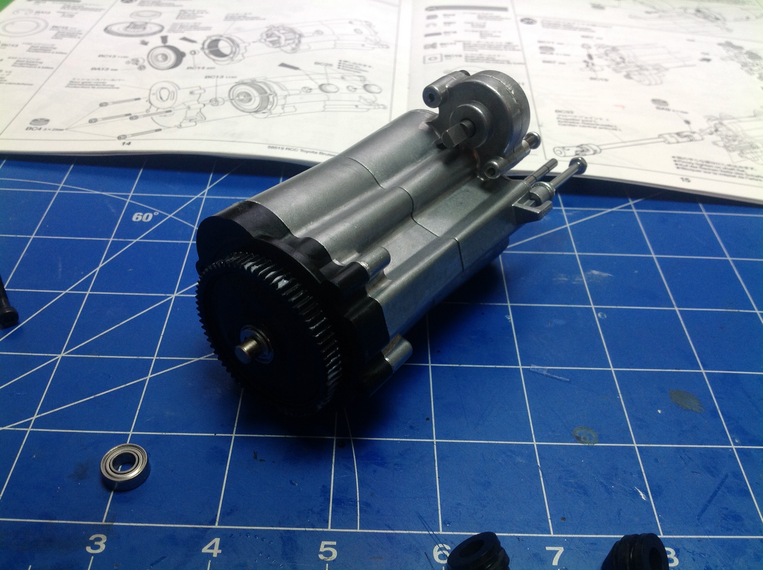
housings are cast aluminum, and the build starts in Step 18 with the
installation of a pair of spur gears rolling on bearings. The
screw protruding from the end cap is used to support the
transmission. The two gears in the second image are not part of
the system to change
gear ratios, but rather drive the transfer case. This
transmission is only four wheel drive in first gear, so these gears are
connected to the lowest gear on the main shaft.
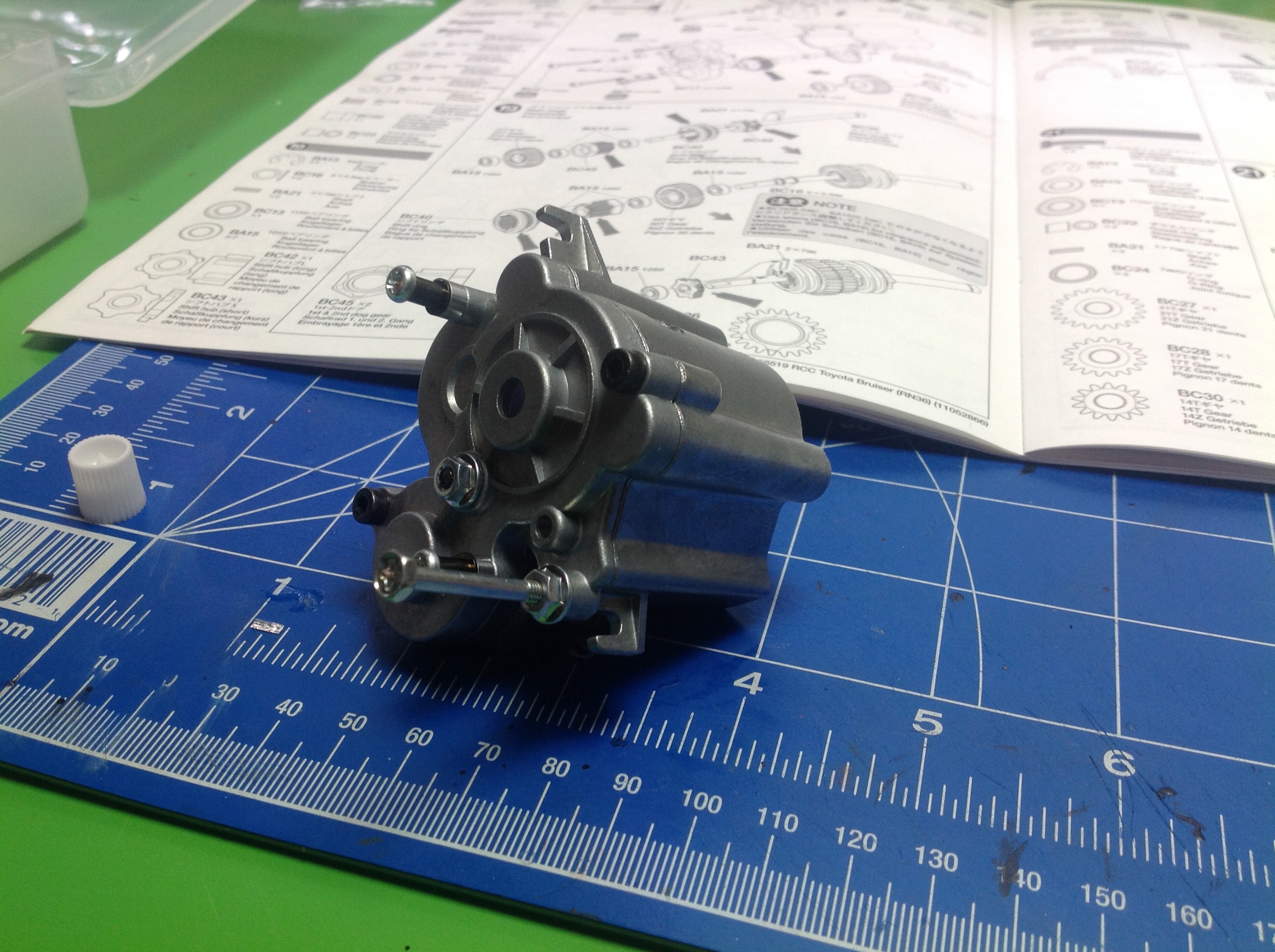
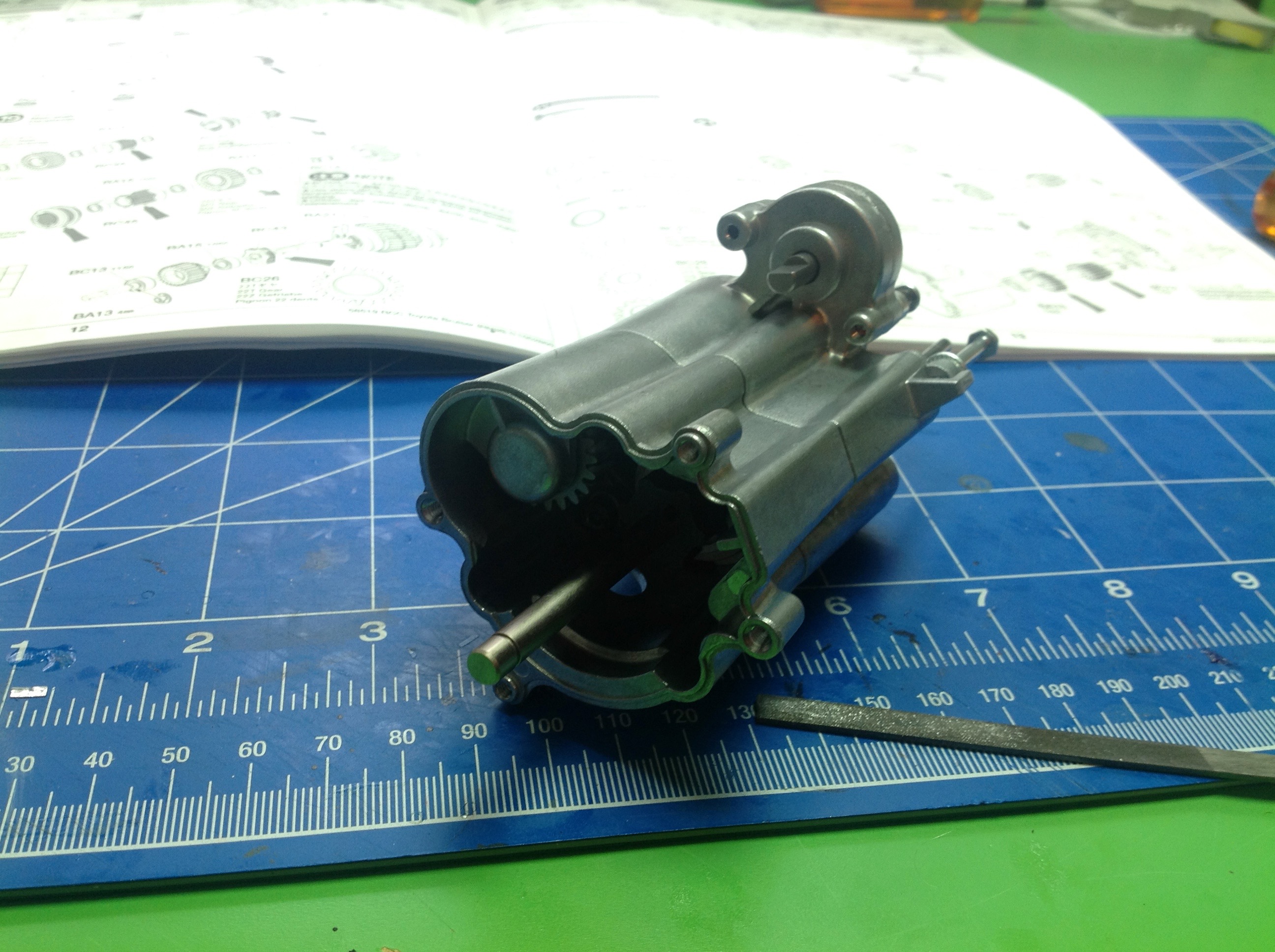
Once the first two housing sections are bolted together, the transmission looks like this.
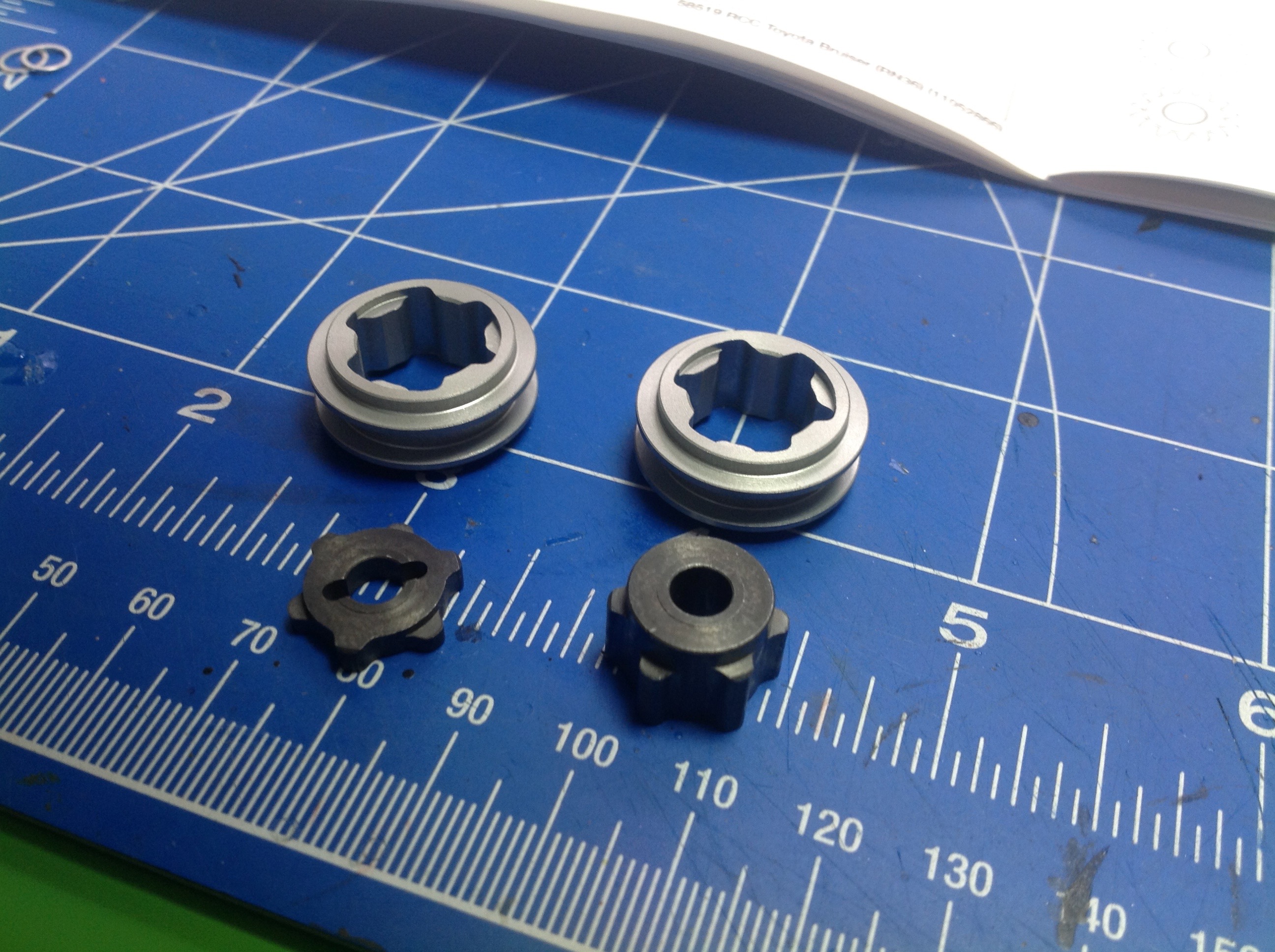
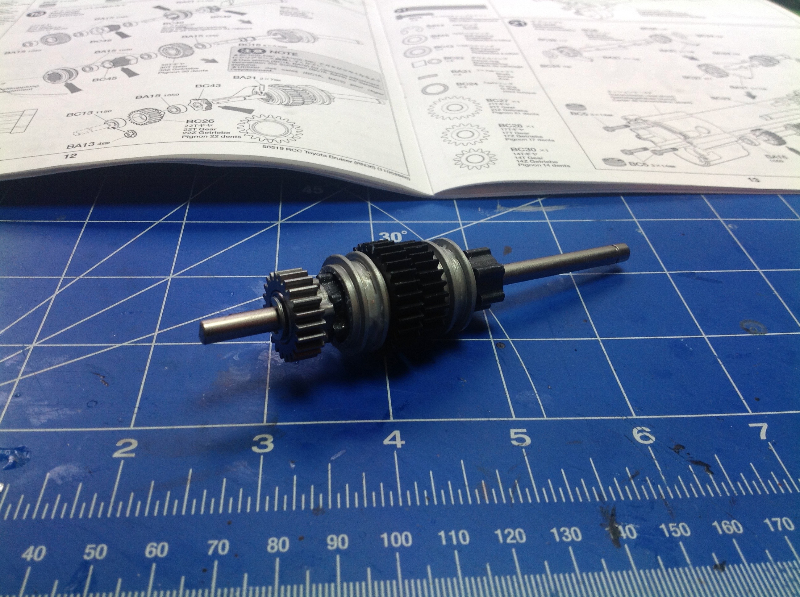
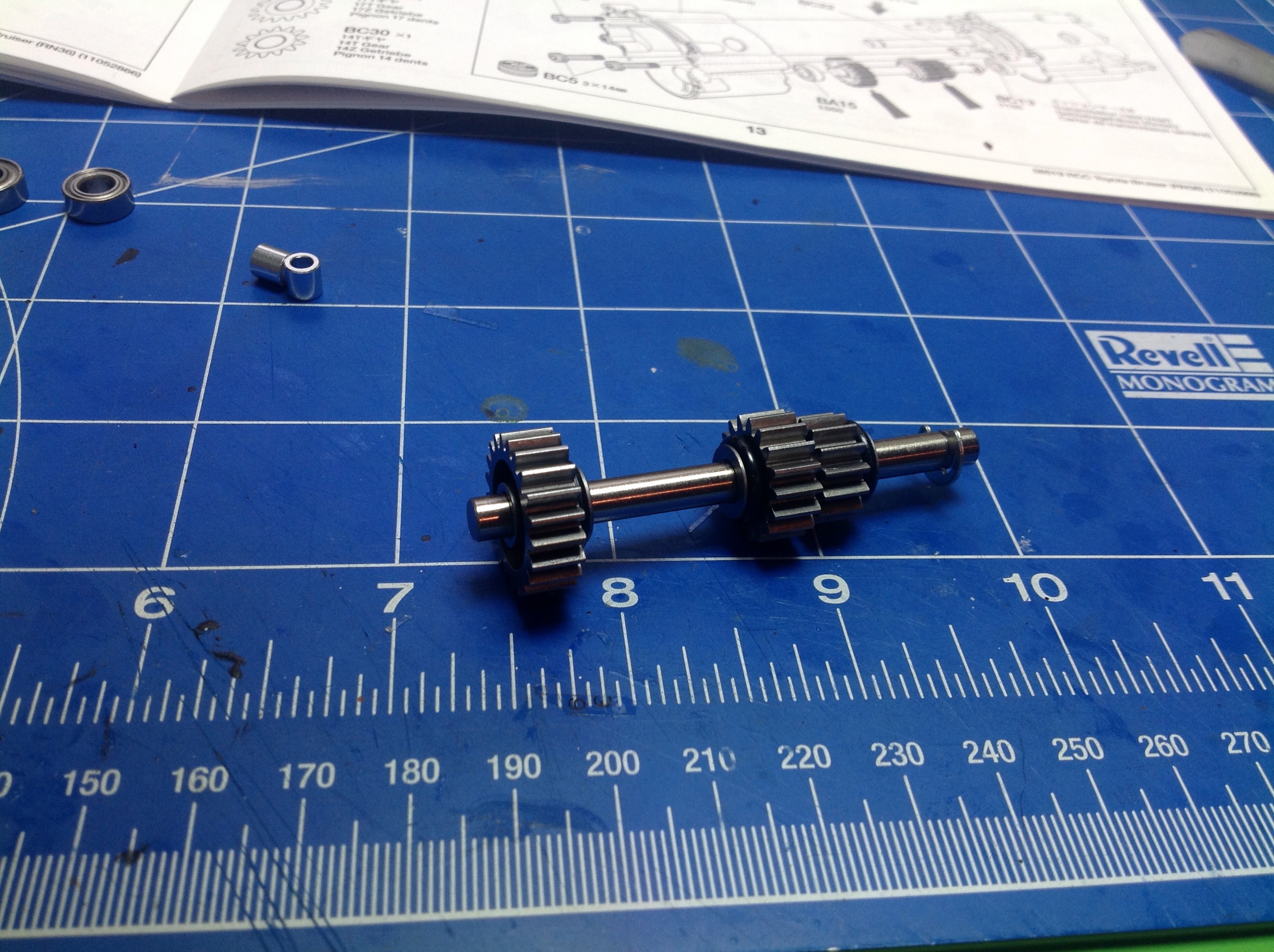
Next comes the build of the main shaft. The parts shown in the
left hand image are the driving rings. The darker parts are keyed
to the shaft. The lighter aluminum collars slide along the drive
rings and engage floating gears. The right hand image shows the
completed main shaft. There are 3 gears: a 30 tooth, a 27 tooth,
and a 22 tooth. Each floats on bearings and does not engage the
shaft unless the collars grab them. The 22 tooth gear drives the
transfer case and does not control ratio changes.
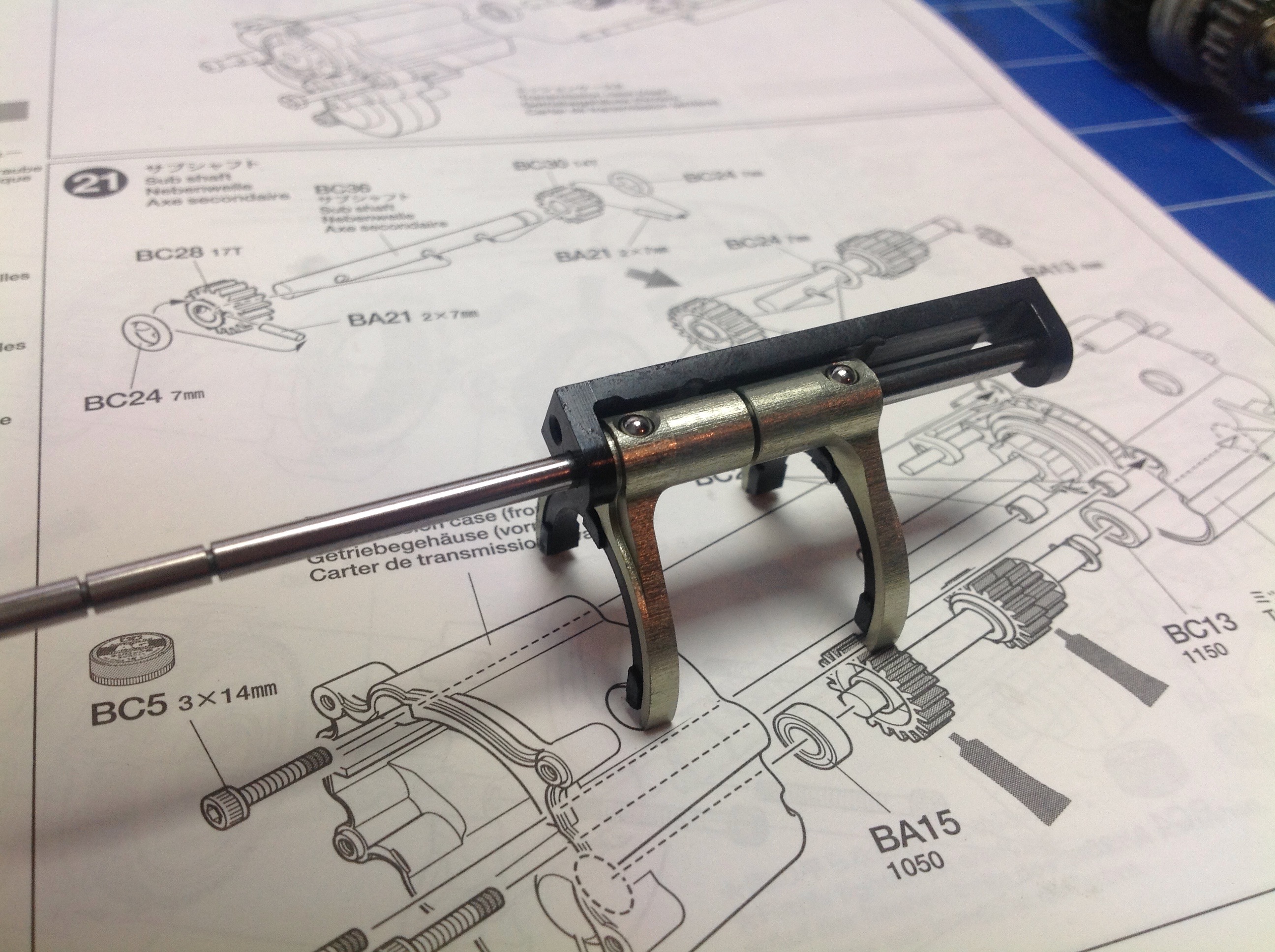
The shift forks contain the magic. You can't simply translate both
shift forks at the same time. This would engage multiple gears
and jam the transmission. You would expect to need 3 shift forks
for a 3-speed, so how do you do it with only 2? The answer is the
little raceway for the balls that drive the shift forks. The
C-shaped dark part in the left hand image contains the raceway.
Each shift fork has a hole for a ball. When the balls are in a
raceway detent they can stand proud of the forks which then slide along
the axle (which is driven by a
servo) When the raceway drives a ball into a detent in the rod,
the fork is
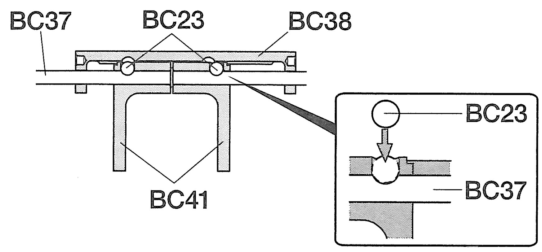
pushed to follow the rod. It is really hard to describe and just
as hard to figure out even when you have the parts right in front of
you, so the picture on the right might help. This is an excerpt
from Step 20 of the manual which shows the balls, the forks, the rod,
and the raceway.
Note the plastic "shoes" on the shift forks which help to minimize
friction as the driving rings rotate beneath them. The kit comes with
extras for when these wear out.
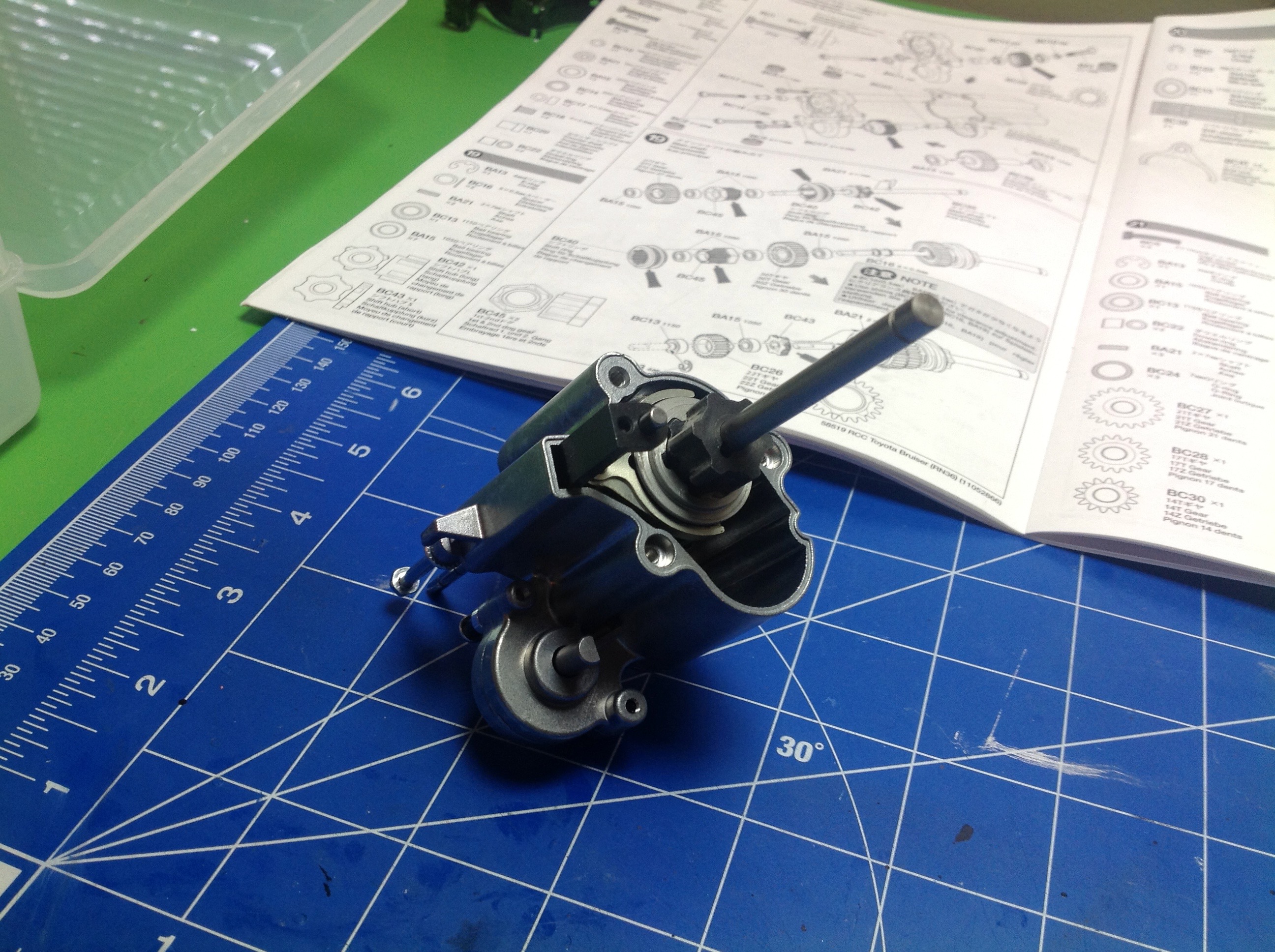
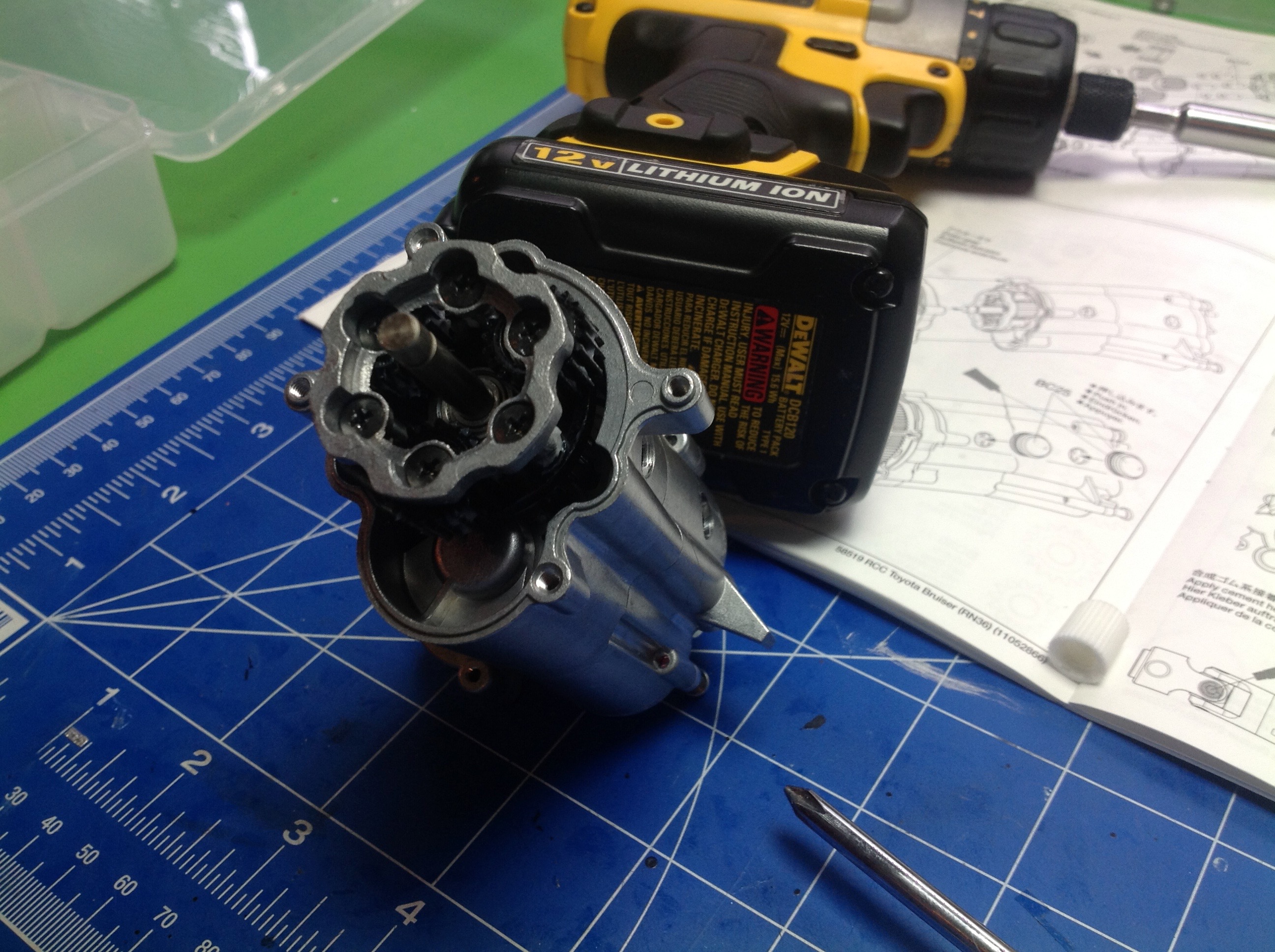
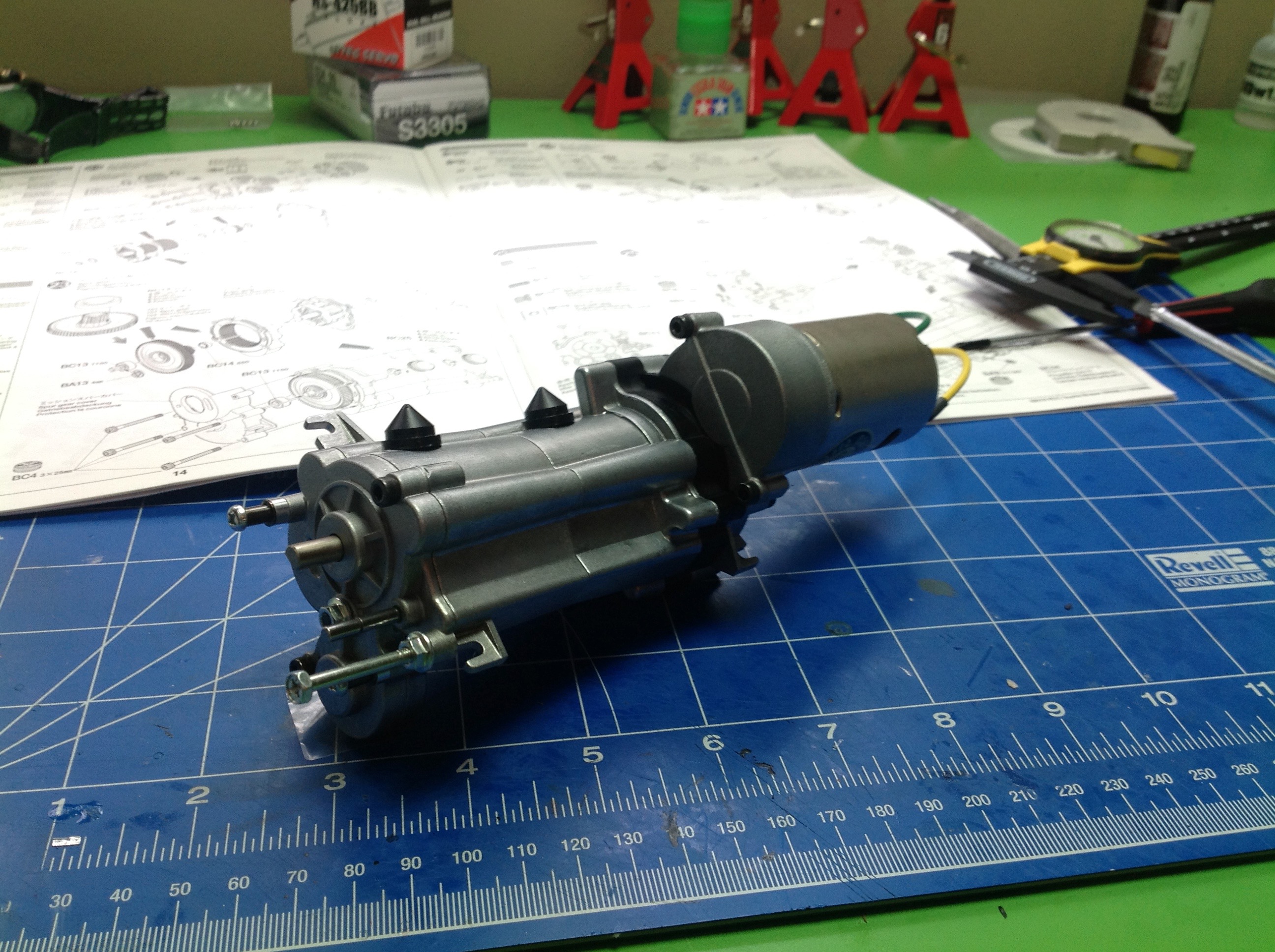
Now the shift rod assembly needs to be mated to the main shaft and the
pair needs to be carefully inserted into the housing. There is a
rectangular support for the raceway which keeps it aligned with the
shift rod.
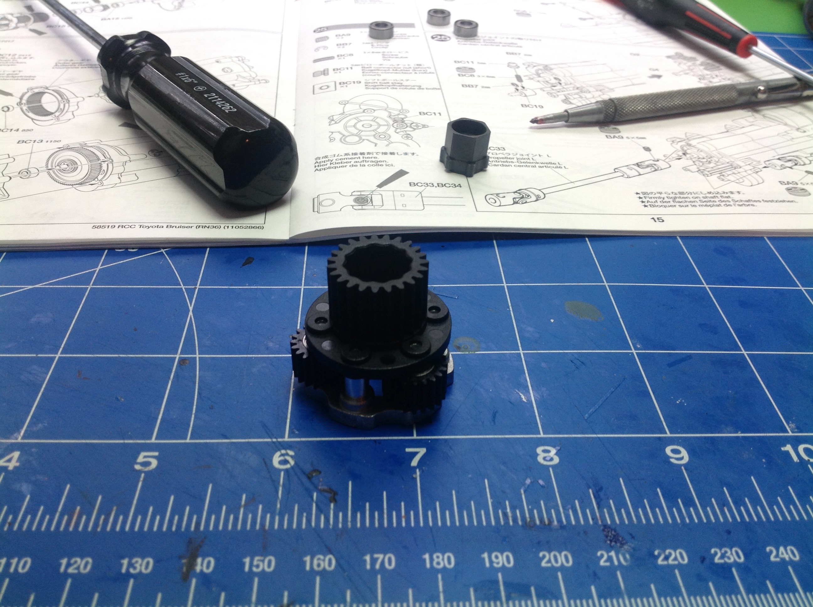
Next is the secondary shaft. Like the main shaft this has 3 gears
on it, but unlike the main shaft these are all locked to the axle.
We have 14 teeth, 17 teeth, and 21 teeth here. All three gears
control ratio changes, but the largest does not mate with anything on
the main shaft. It's mating gear comes in Step 22 below.
The first stage of the gearbox is this planetary system. The big
output gear is connected to the planet carrier and has 23 teeth.
Each of the 3 planet gears has 20 teeth. The planetary assembly is
inserted into the gearbox housing where the 23 tooth output gear mates
with the last gear of the secondary shaft.
In case it wasn't complicated enough yet, now we get to add a plastic 59 tooth
ring gear to mate with the orbiting planets. The 70 tooth spur
gear has an integral 19 tooth sun gear for driving the planets.
The final step in building the transmission is to attach the motor and 19 tooth pinion. Phew!
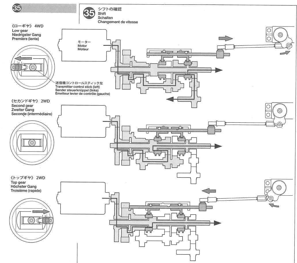
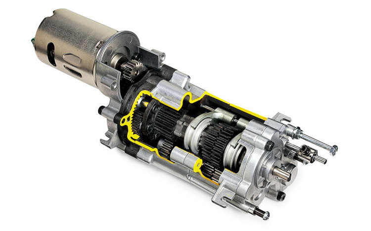
This path through this gearbox is about as convoluted as they come, but
luckily Step 35 in the manual is not a step at all but an explanation of
the torque path through the gearbox, shown above (click for a larger
version). With this assistance of this picture, we should be able
to derive all the final gear ratios. Let's break the problem into
parts:
- Motor Ratio = 70:19 = 3.684:1
- Planetary Ratio = 1+(59/19) = 4.105:1
- 1st Gear = 21:23 x 30:14 = 1.957:1
- 2nd Gear = 21:23 x 27:17 = 1.450:1
- 3rd Gear = 1:1 (Note that 3rd gear goes straight through and doesn't use the secondary shaft at all)
- Transfer Case = 22:15:22 = 1:1
- Differential = 24:13 = 1.846:1
Therefore final drives are:
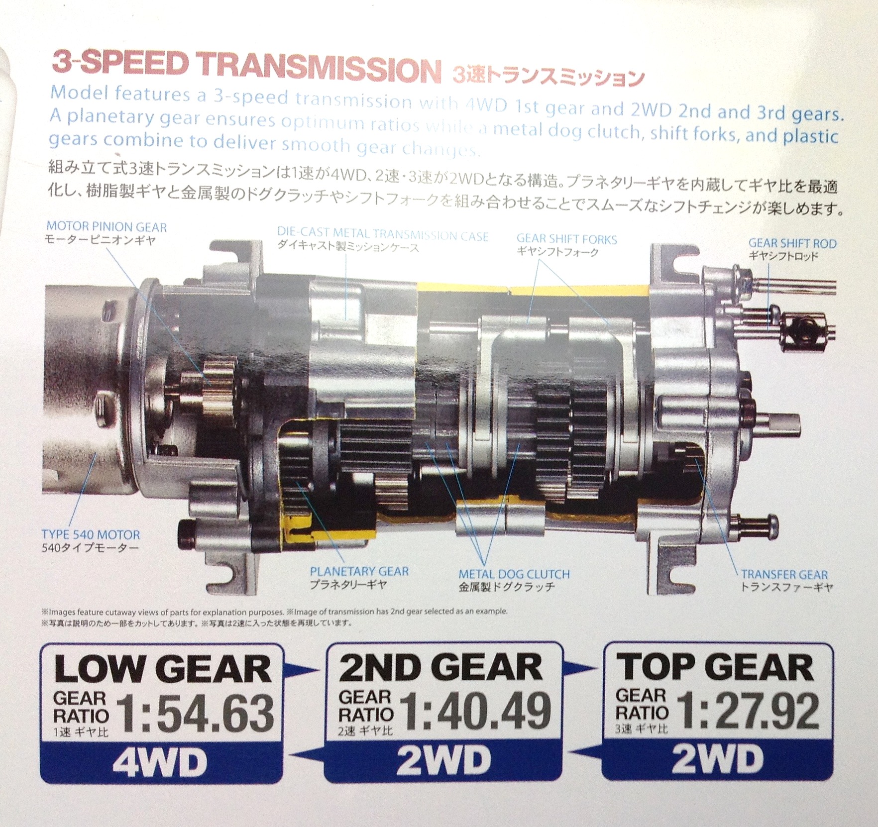
- 1st Gear = 3.684 x 4.105 x 1.957 x 1.846 = 54.6:1
- 2nd Gear = 3.684 x 4.105 x 1.450 x 1.846 = 40.5:1
- 3rd Gear = 3.684 x 4.105 x 1 x 1.846 = 27.9:1
I am happy to report that I did this entire exercise without first looking at the picture on the box and I got the same answers!
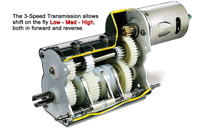
If we compare the 3-speed transmission in the Bruiser with the 3-speed
transmission in a 1/14th scale tractor truck or Highlift truck, we can see the significant
differences. They both have two axles, but the Bruiser has 2
shift forks while the tractor has 3. The tractor transmission uses
driving dogs which make it easy to shift gears at any speed. The
Bruiser driving rings need to be synchronized to allow the lobes to slip
into place, so sometimes it takes a moment to shift or even refuses
until the right RPM is reached. The Bruiser has the additional
function of engaging the transfer case in first gear and freewheeling in
other gears. Finally, only the Bruiser has the cool planetary
reduction. With all this extra complexity probably comes less
reliability, but so far I have had no problems with either. The
Bruiser version is quite a challenge to build and get right
though. It took me a couple of tries to get everything lined up correctly .
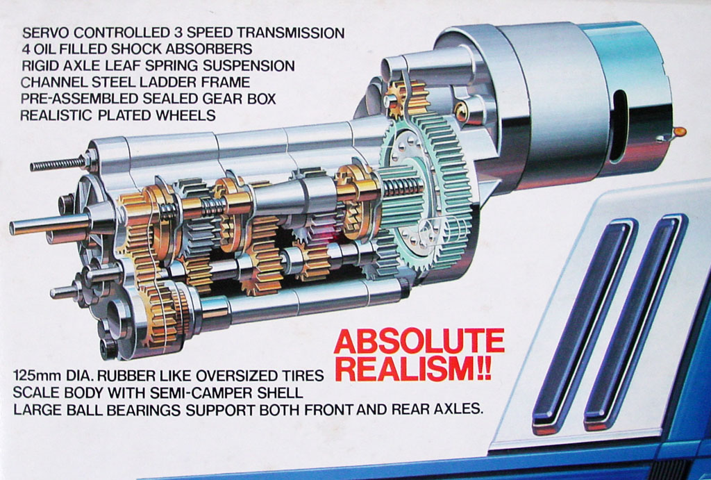
Just for fun we can look back at the original Bruiser transmission from
1983 and see that it is significantly different. Besides using a
750 sized motor, is also lacks the planetary reduction and uses 3 shift
forks.
©2017 Eric Albrecht