Tamiya Mercedes G500 Project
Page 1: Building the Chassis
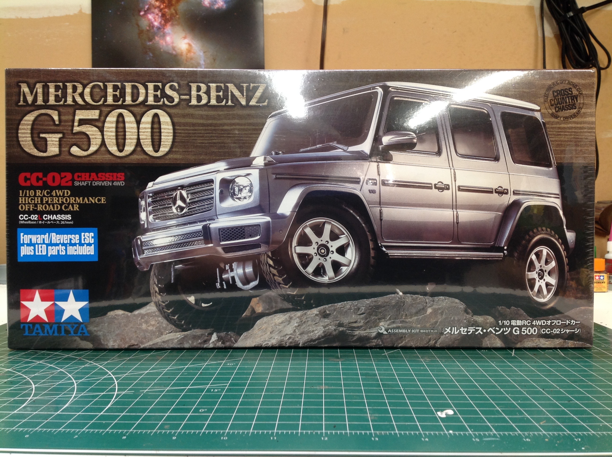
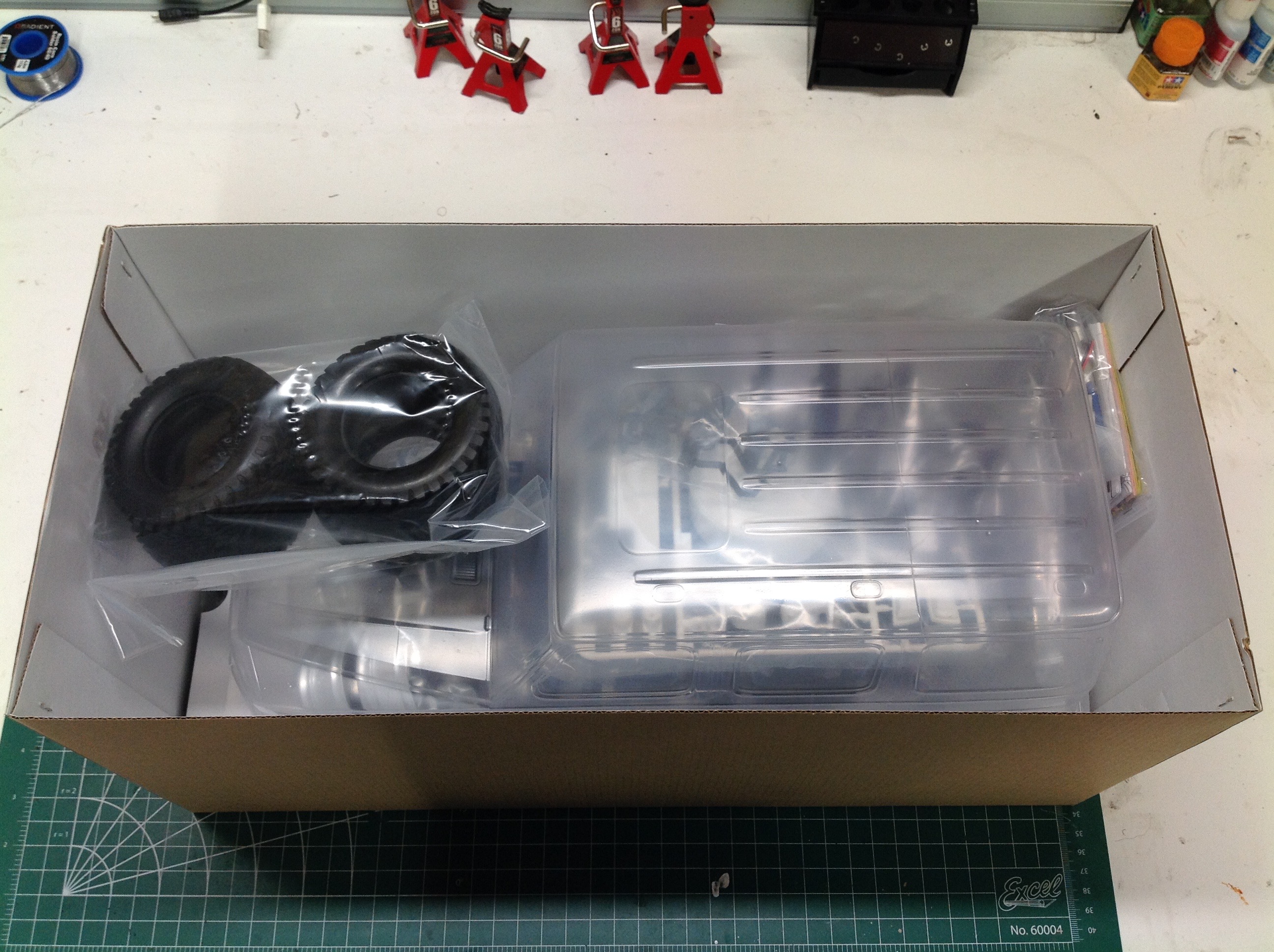
This very first CC-02 model comes in a box very similar in size to a
typical CC-01, though somewhat deeper. That extra depth is to make
room for the quite sizeable G500 body which is about all you can see
when you open the box. Apart from the tires, everything else is
packed beneath the body shell.
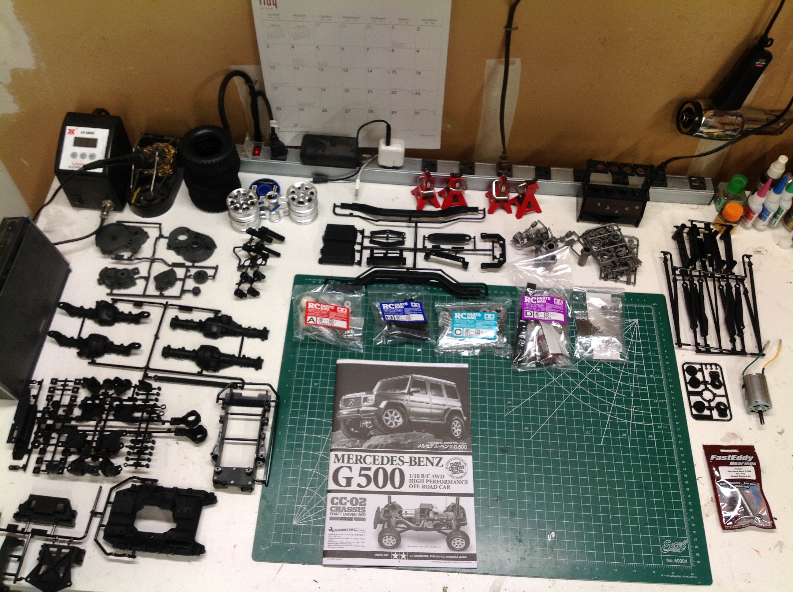
You can already tell this is not going to be a simple chassis based
purely on the number of parts trees and hardware bags included.
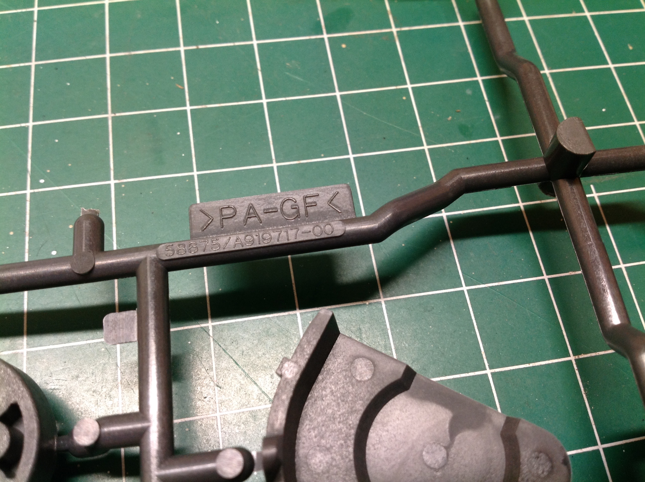
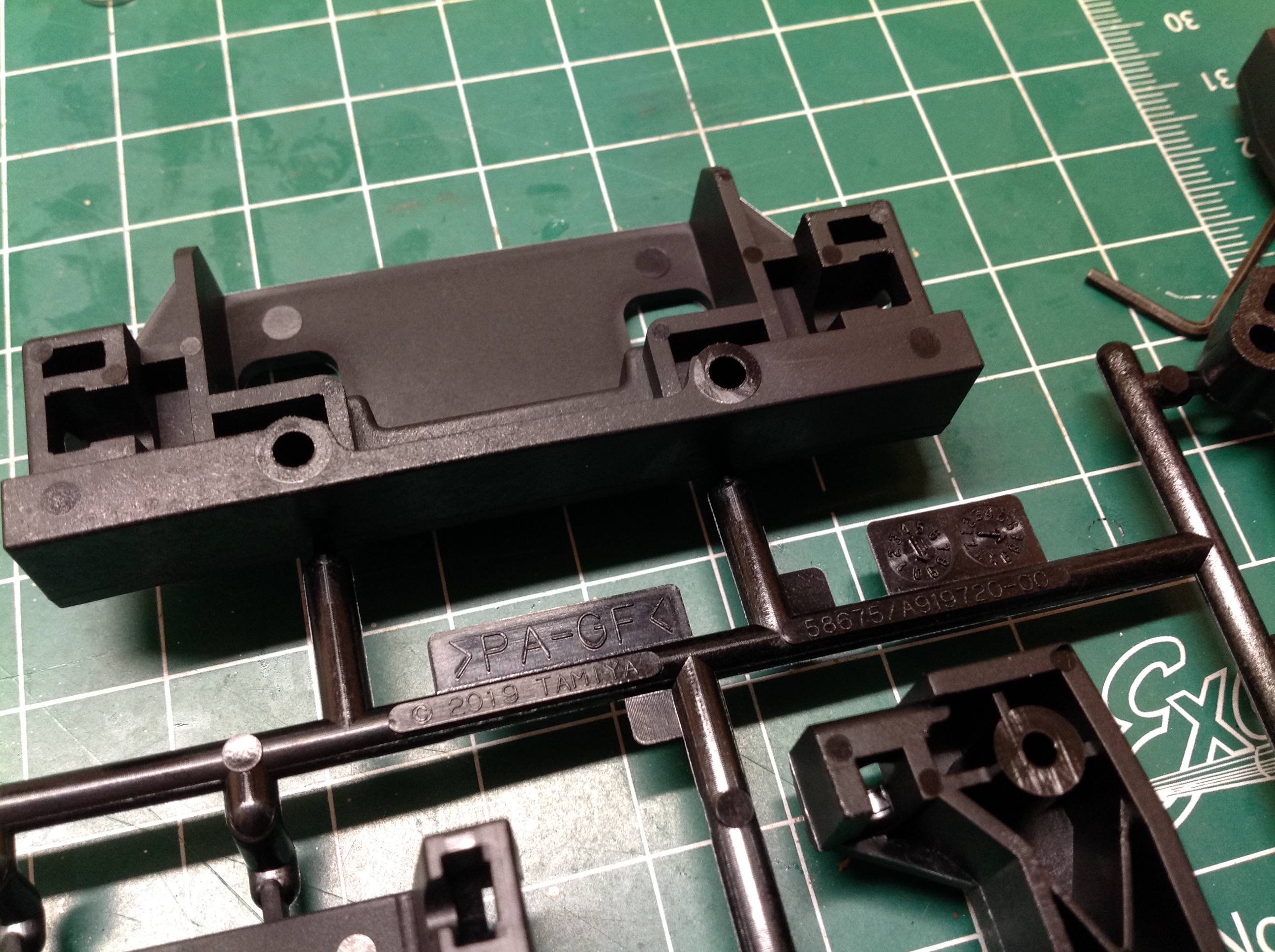
Most of the trees are black and only a couple are dark gray, but from
what I can tell all are glass filled Nylon (example shown at right) for
strength and stiffness.
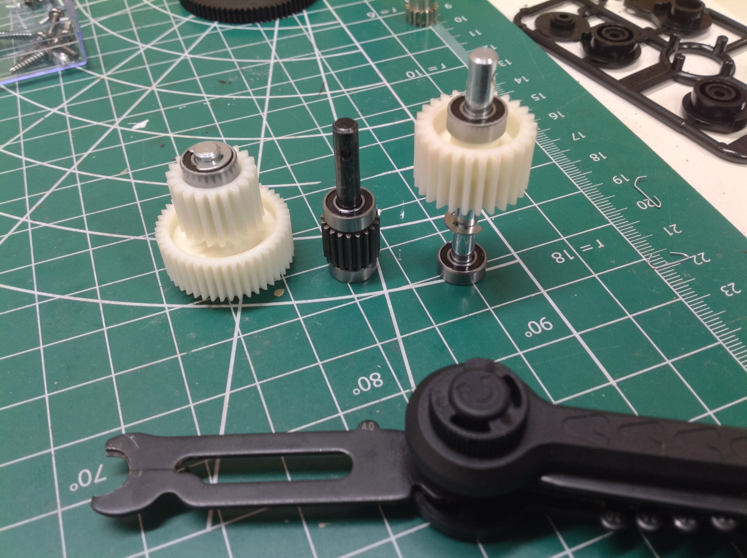
The transmission uses 3 gears (2 pairs). The 2nd pair can be
installed two ways. If the smaller gear is used as a driver, you
get a gear reduction and a low speed ratio. If the larger gear is
used as a driver, you get a gear increase and a high speed ratio.
Since one of the major issues with the CC-01 was too high gearing, I
used the low ratio as shown. Note that the kit came with plastic
bushings but I immediately switched to ball bearings.
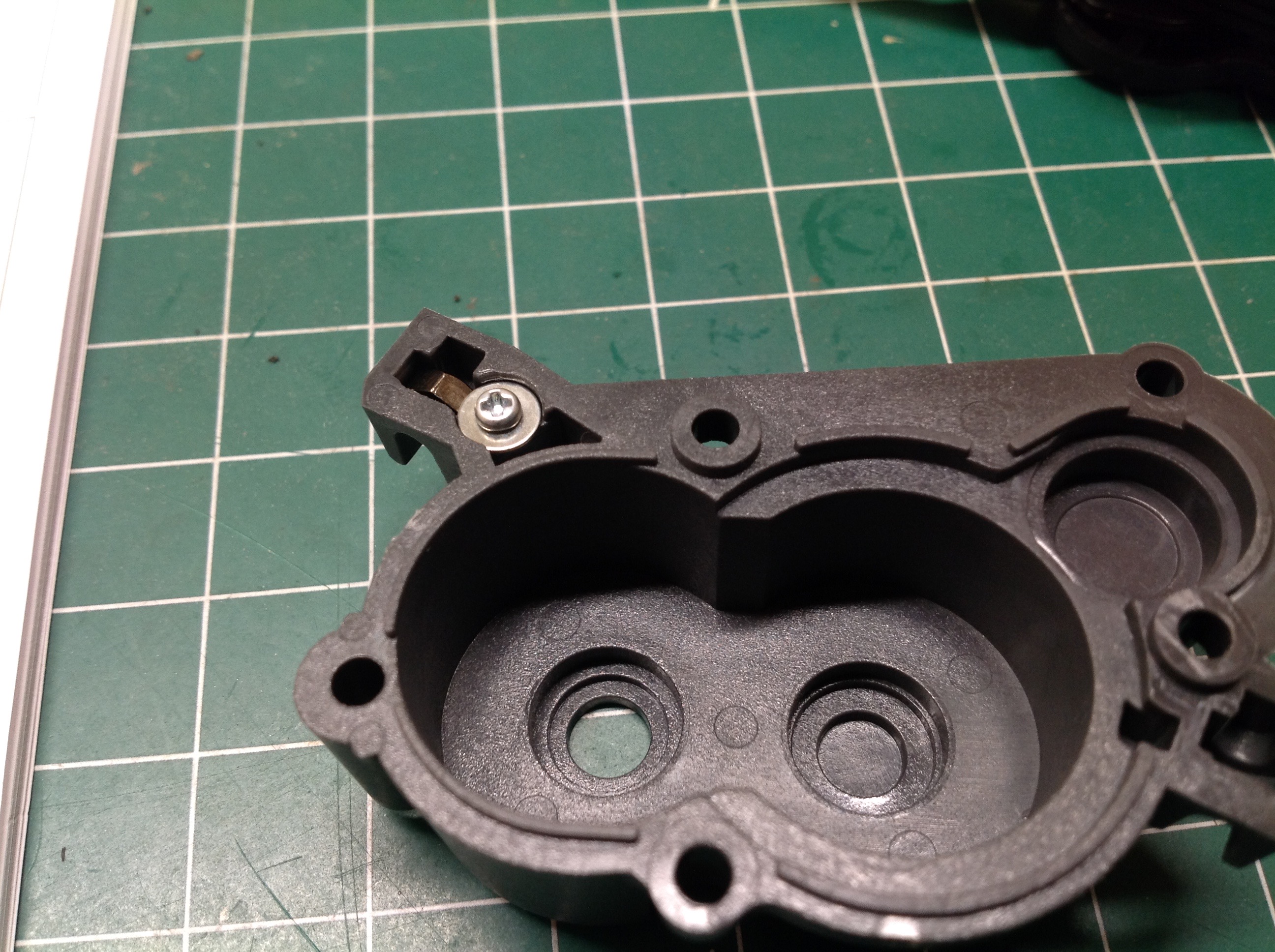
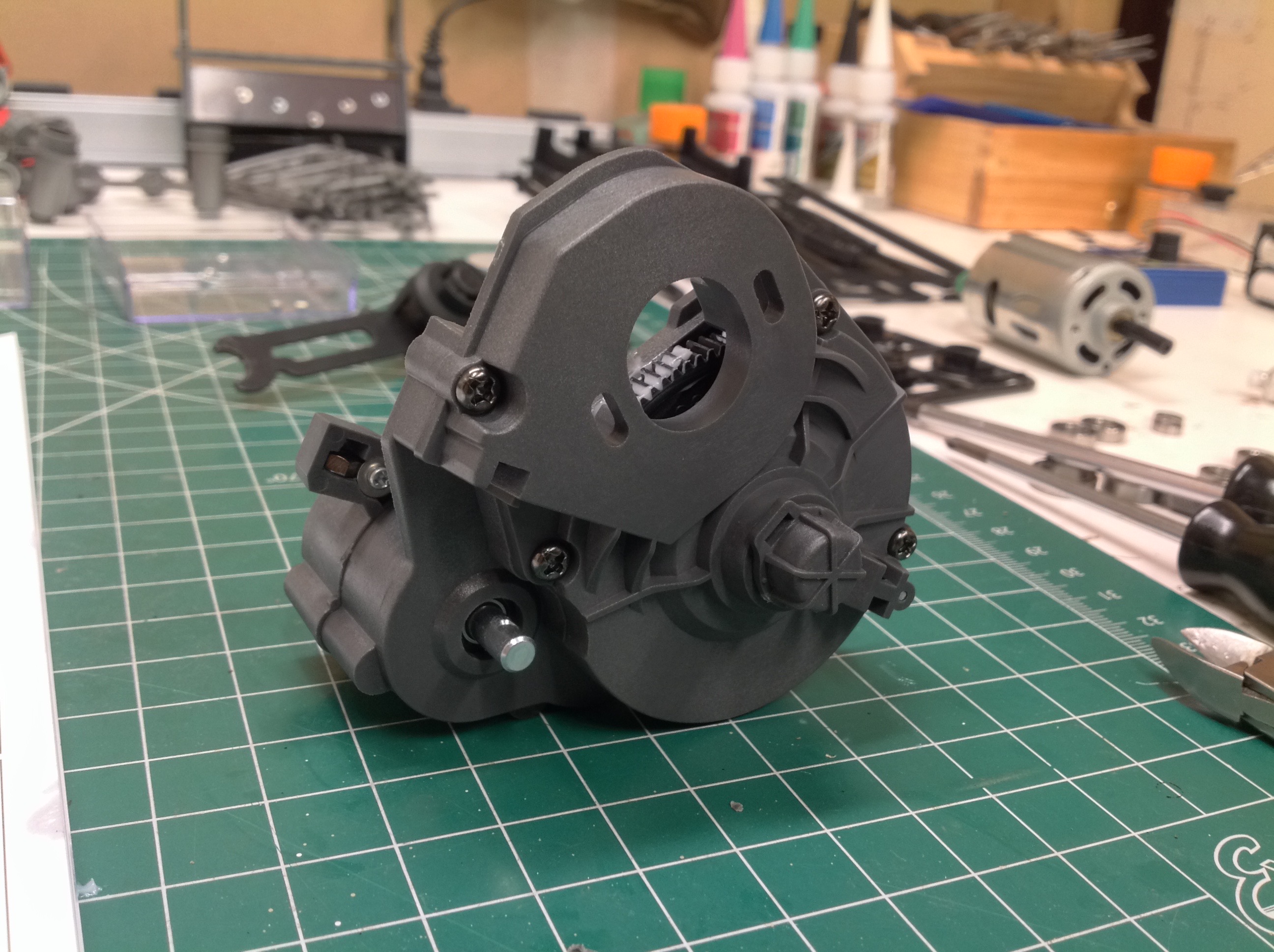
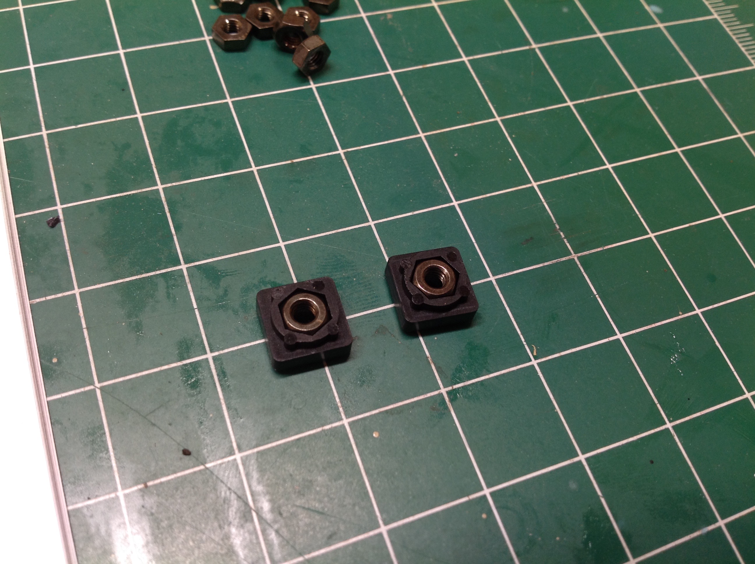
Directly tapping into glass filled plastic is not a great idea because
it tends to be quite brittle and can crack. Wherever possible,
Tamiya uses nuts instead. Many of them are installed in a strange
manner. On the left, you can see a nut in a slot trapped by an
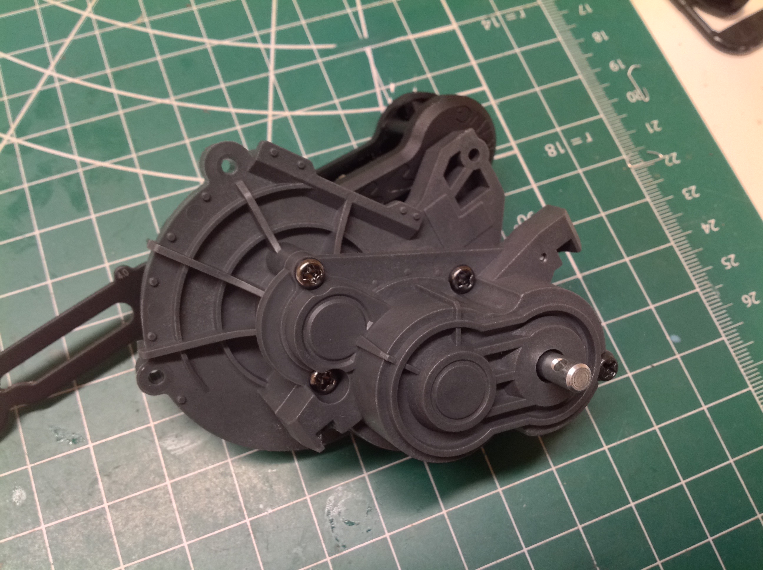
overlapping washer in the transmission housing. The right hand
image shows the sealed up gearbox with only the transfer case output
protruding.
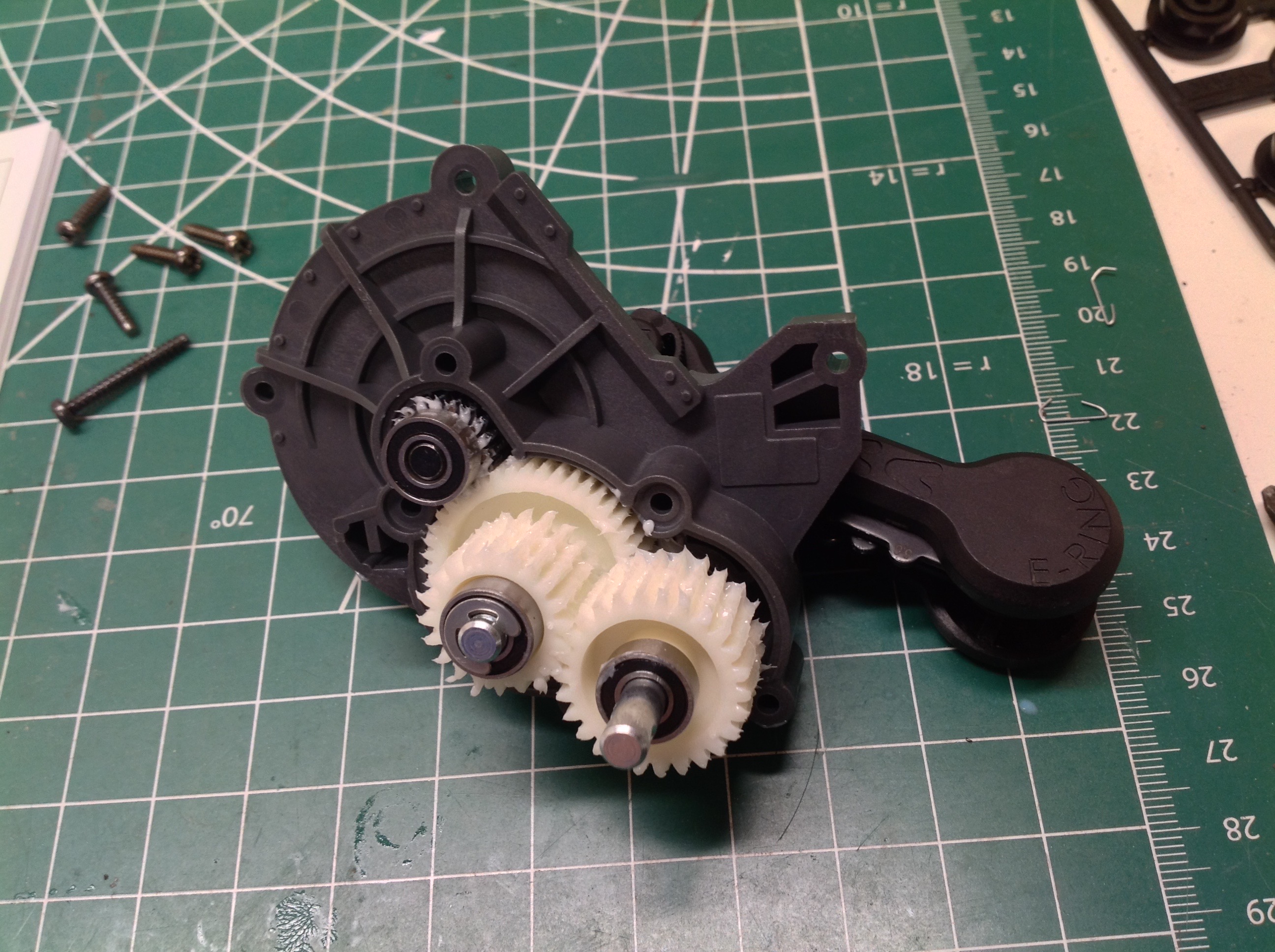
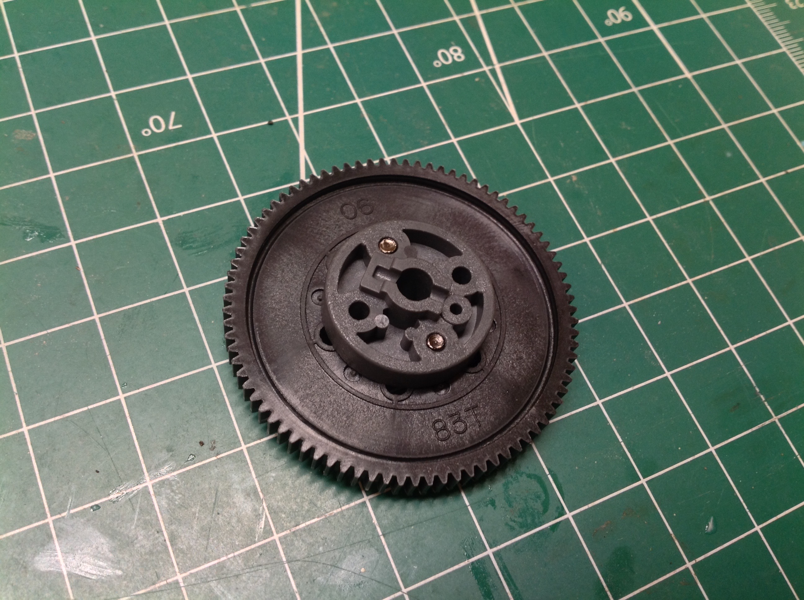
The kit uses a very large 83 tooth spur gear with 0.6 mod pitch.
It seems like the disc attached to the spur could probably be replaced
with a slipper clutch, but none is included nor does an optional slipper
exist at the time of this writing.
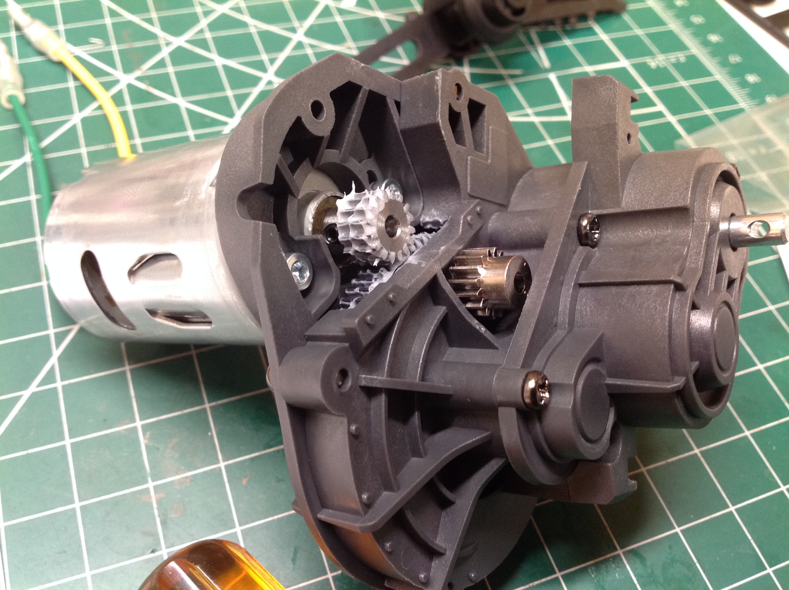
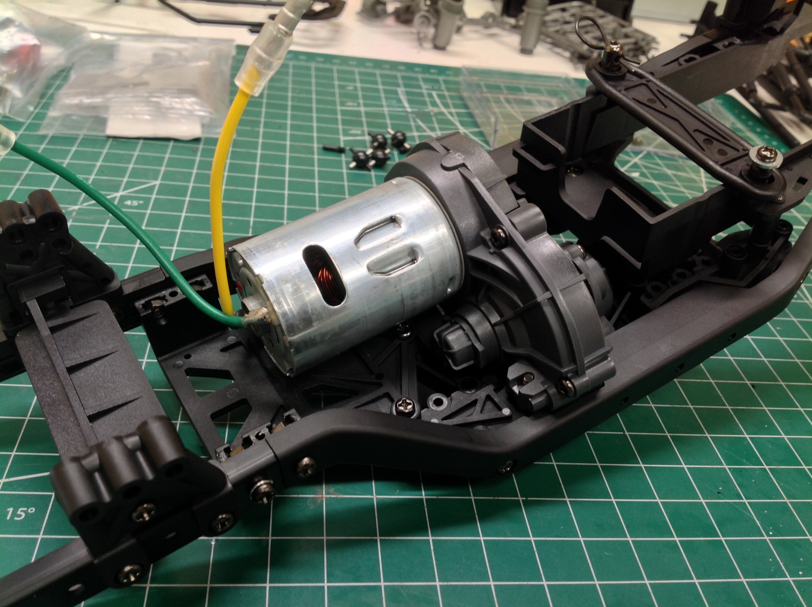
Now the final covers can be attached to the transmission and the motor
installed. The kit comes with a standard 27T silver can which is
really still too fast for a crawler. I replaced the stock aluminum
16T pinion with a steel version. The aluminum pinion is shown
sitting on the housing for comparison. Larger pinions up to 25T
can be used, but nothing smaller.
Now we can start building the chassis which uses more glass filled
parts. Here another way to support nuts is shown on the
right. These square molded blocks hold nuts and are prevented from
rotating by mating parts.
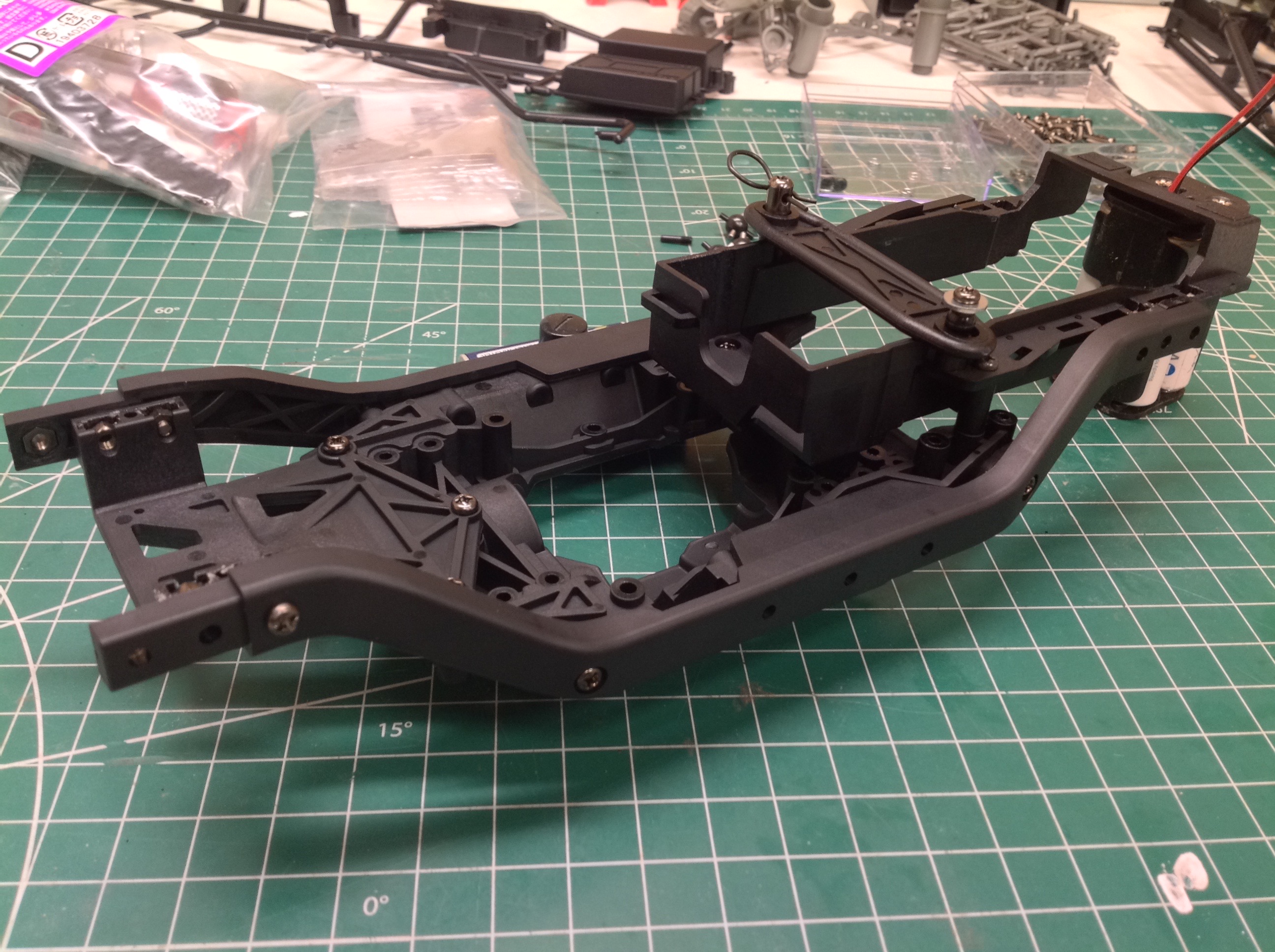
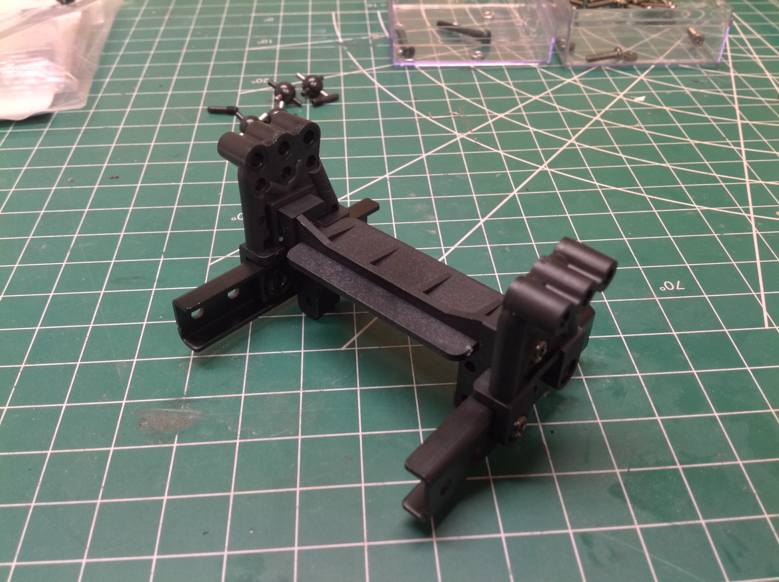
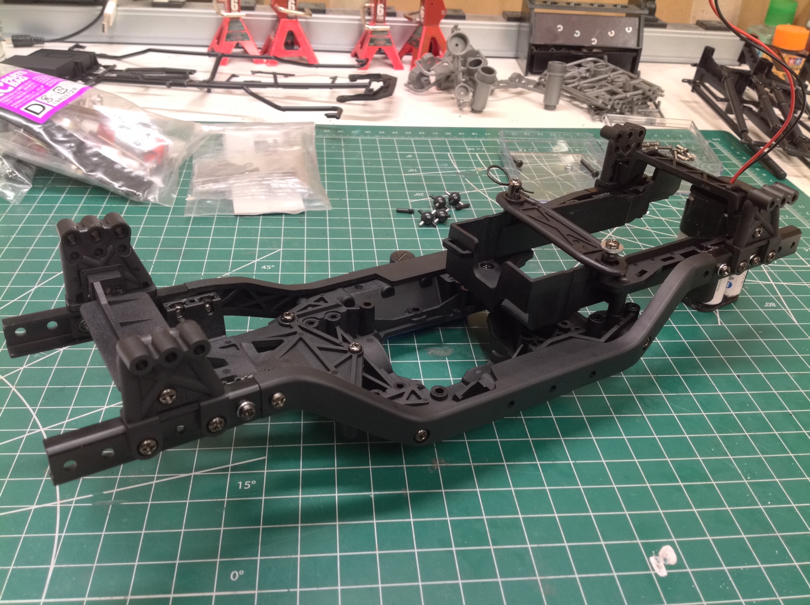
The chassis starts with the cross members, but these are much more than
just I-beams or C-channels. There is a huge molded front part
which will hold the gearbox, the servo, and the electronics. It is
heavily braced and reinforced. The rear longitudinal battery tray
attaches above and behind this and fits modern rectangular Li-Po
batteries. On the right you can see that the molded plastic frame
rails have been attached. Yes, they are plastic but because of the
construction this is still an incredibly rigid chassis.
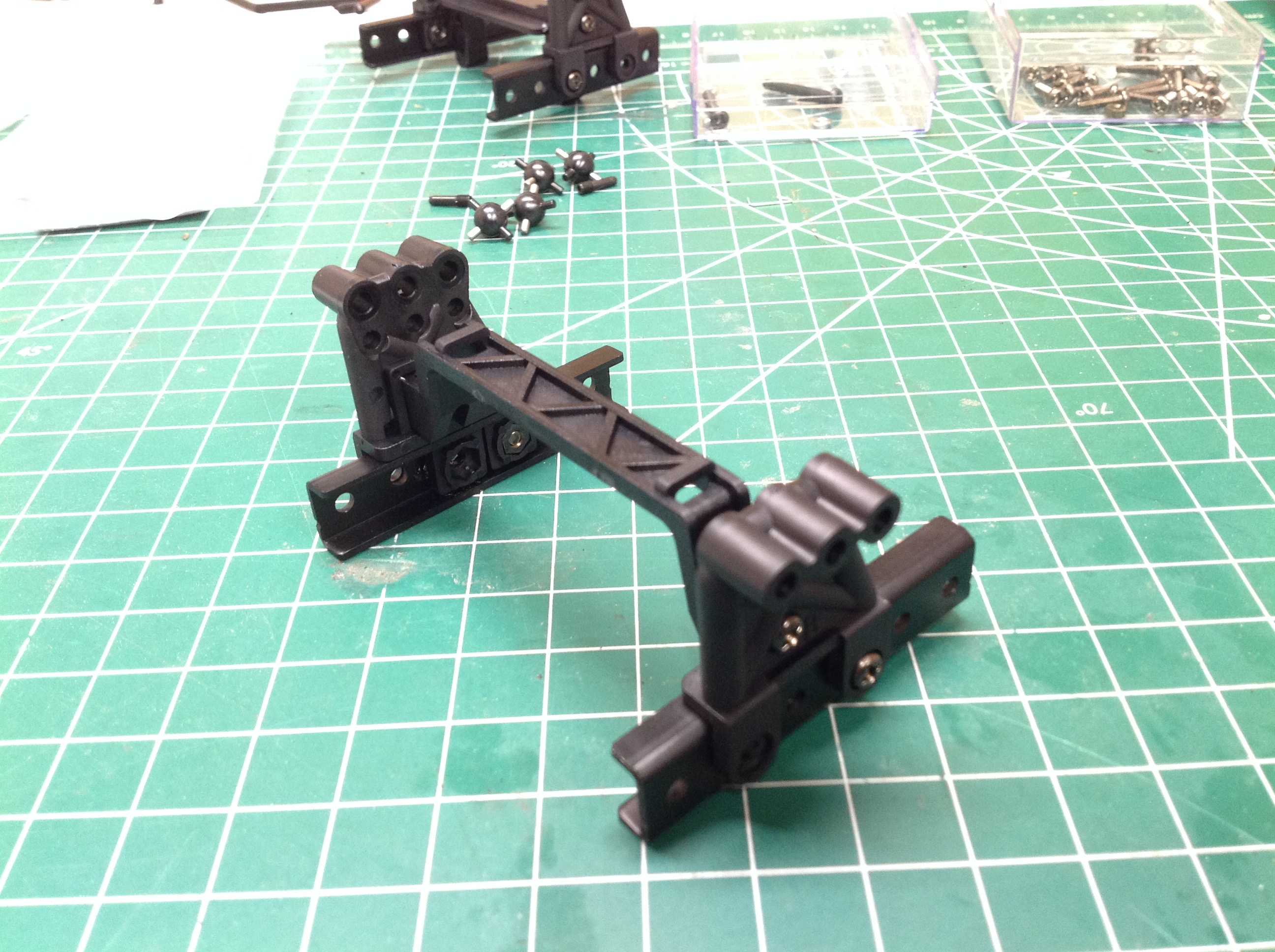
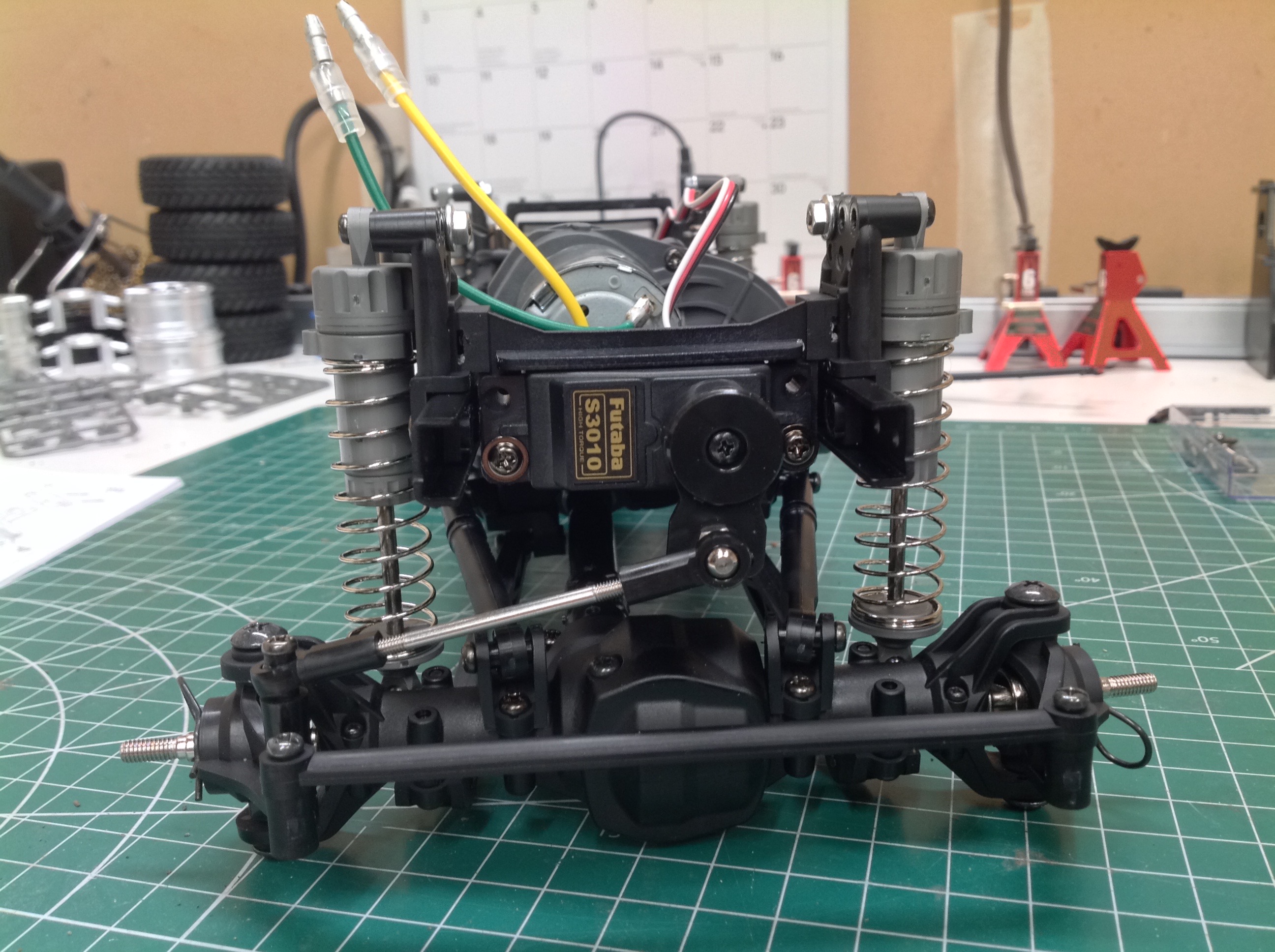
The plastic shock towers are attached to metal frame extensions as
shown. Front and rear shock towers are the same and each feature 3
upper attach points. They also appear to be reversible to
accommodate different wheelbases. The front frame extension houses
the chassis mounted servo which can be installed either horizontally or
vertically.
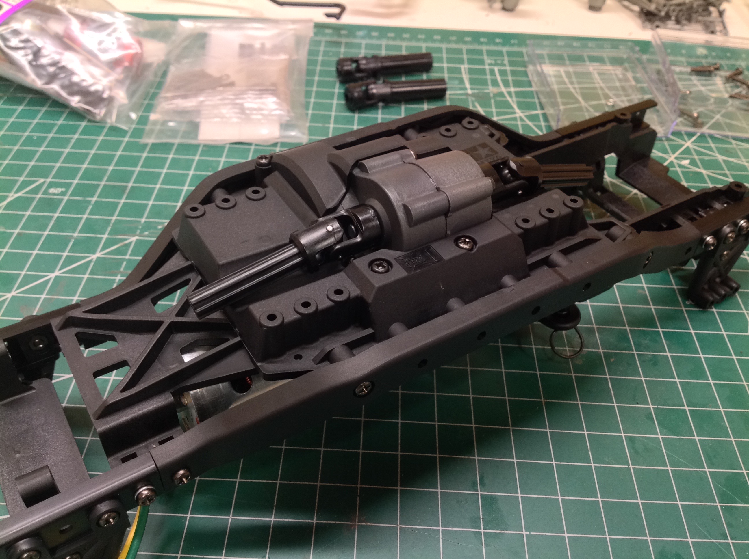
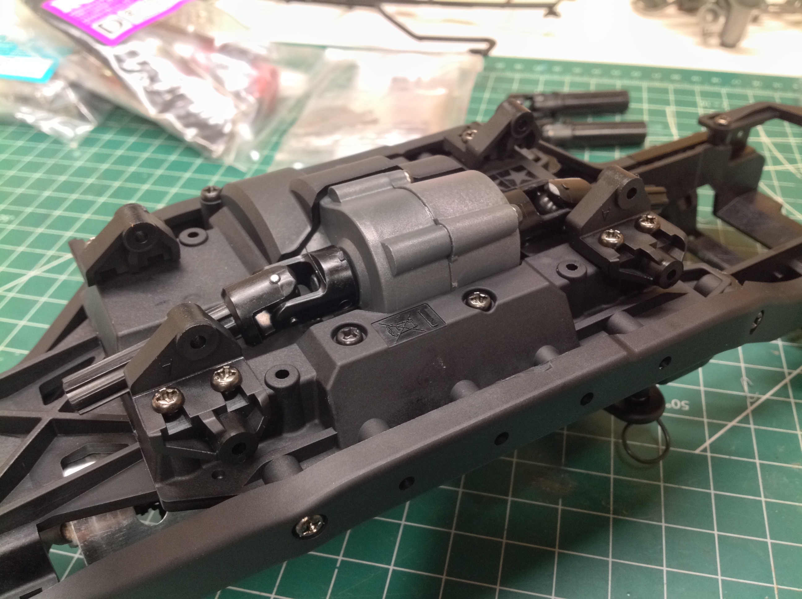
Once the extensions are installed we can see the full length of the
ladder frame. Now the transmission can be installed using 4 screws
from below. It is tricky to get the gearbox aligned. It has
to be tipped, lowered, and then straightened out to fit.
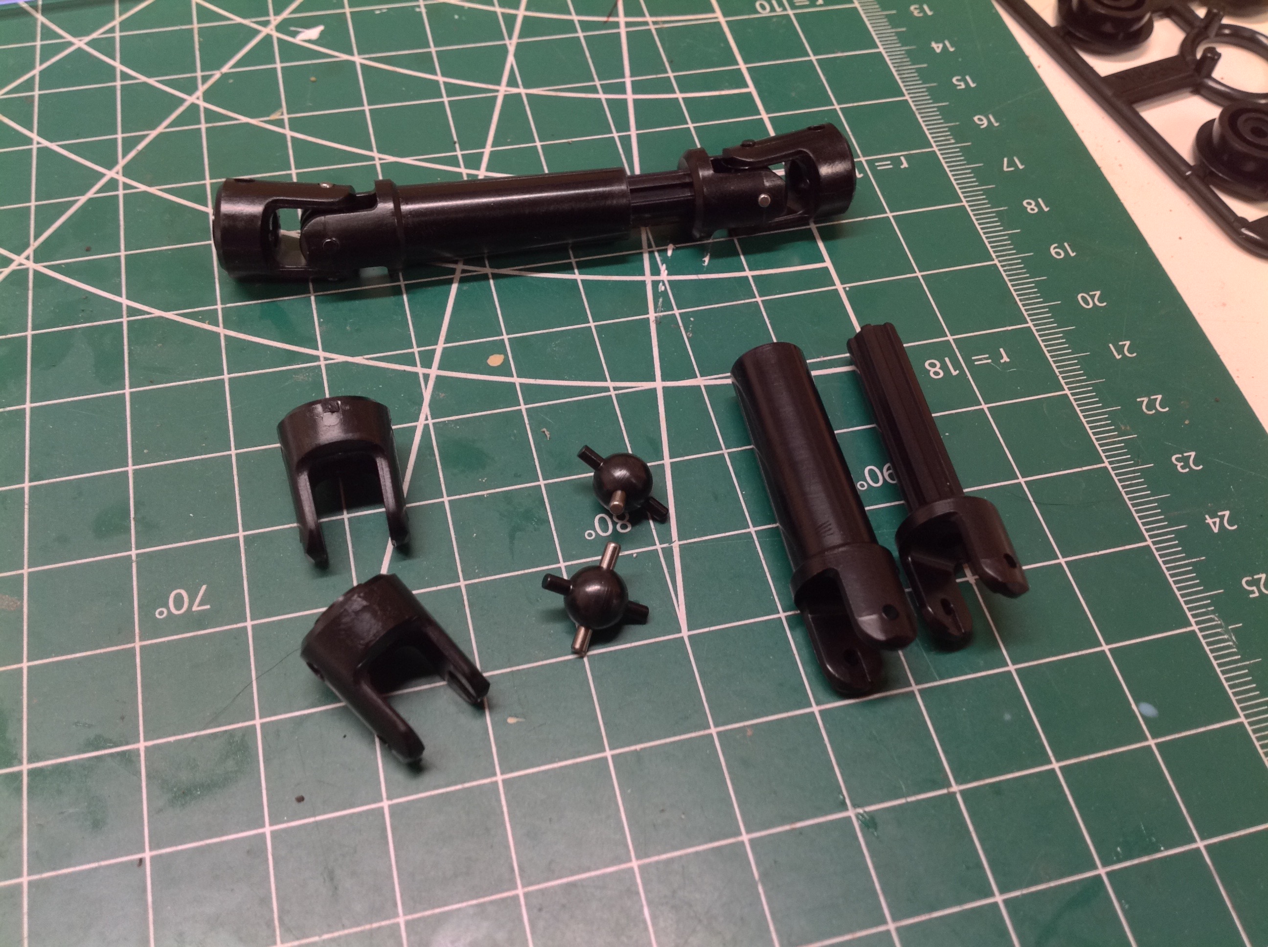
The universal joints of the plastic drive shafts have to be assembled
manually by deforming the yokes. This is pretty easy to do because
the plastic is so soft. This same softness had me worried that
they would pop apart under high torque, but I've had no problem so
far. The male splined ends of the drive shafts are installed to
the transfer case as shown.
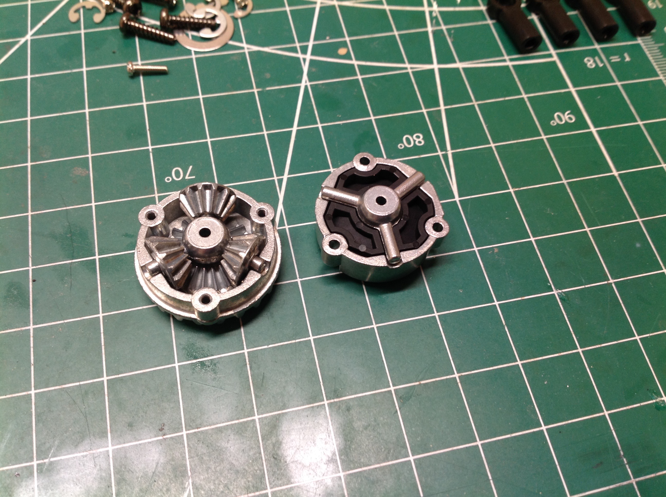
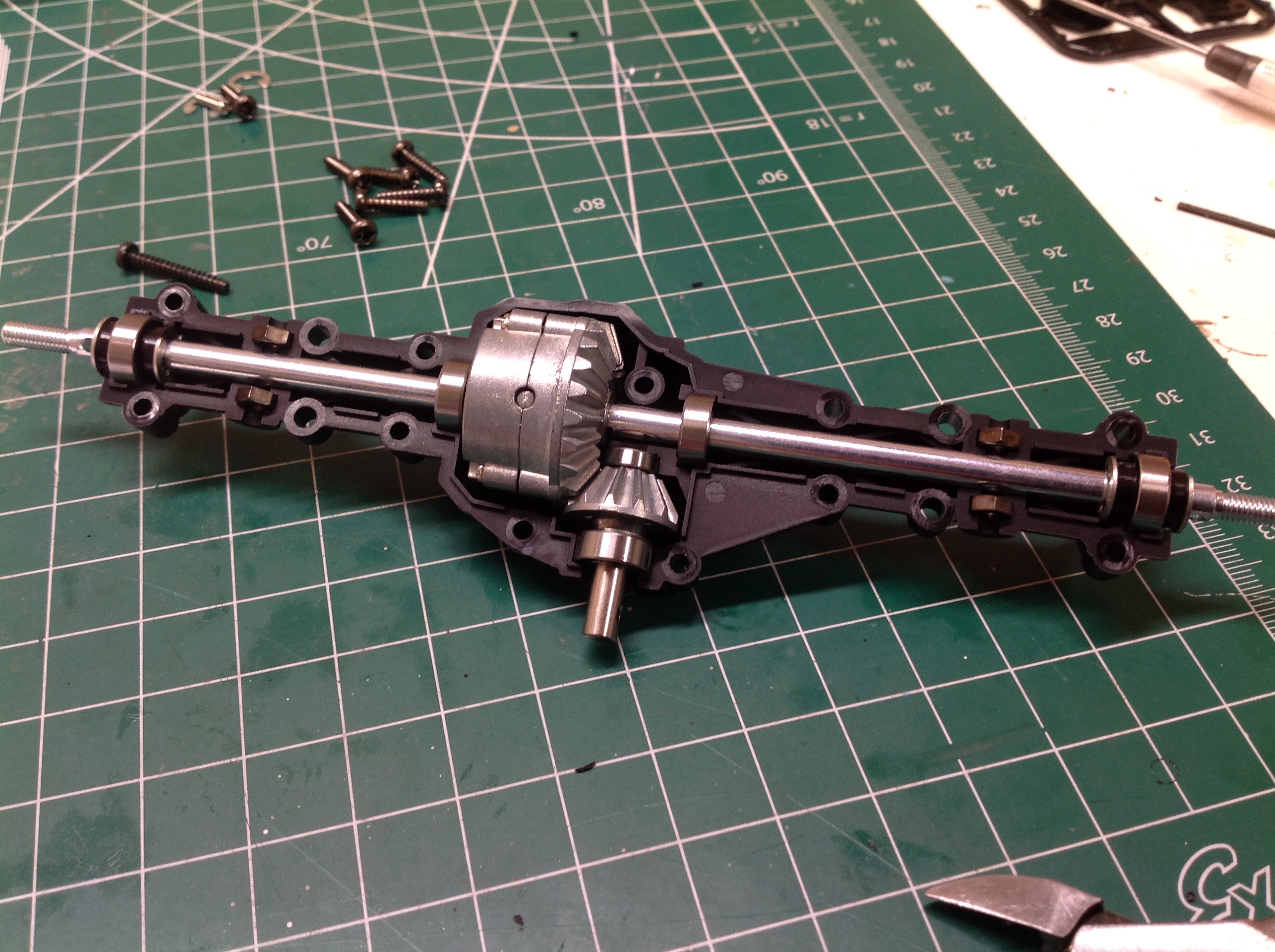
The CC-02 uses exactly the same cast differential parts as the CC-01
which, as far as I can tell, is the only commonality between them.
The version on the far left shows the stock open differential, while
the version just to right shows how to lock the diff by inserting a
plastic locker in place of the spider gears. I fully locked my
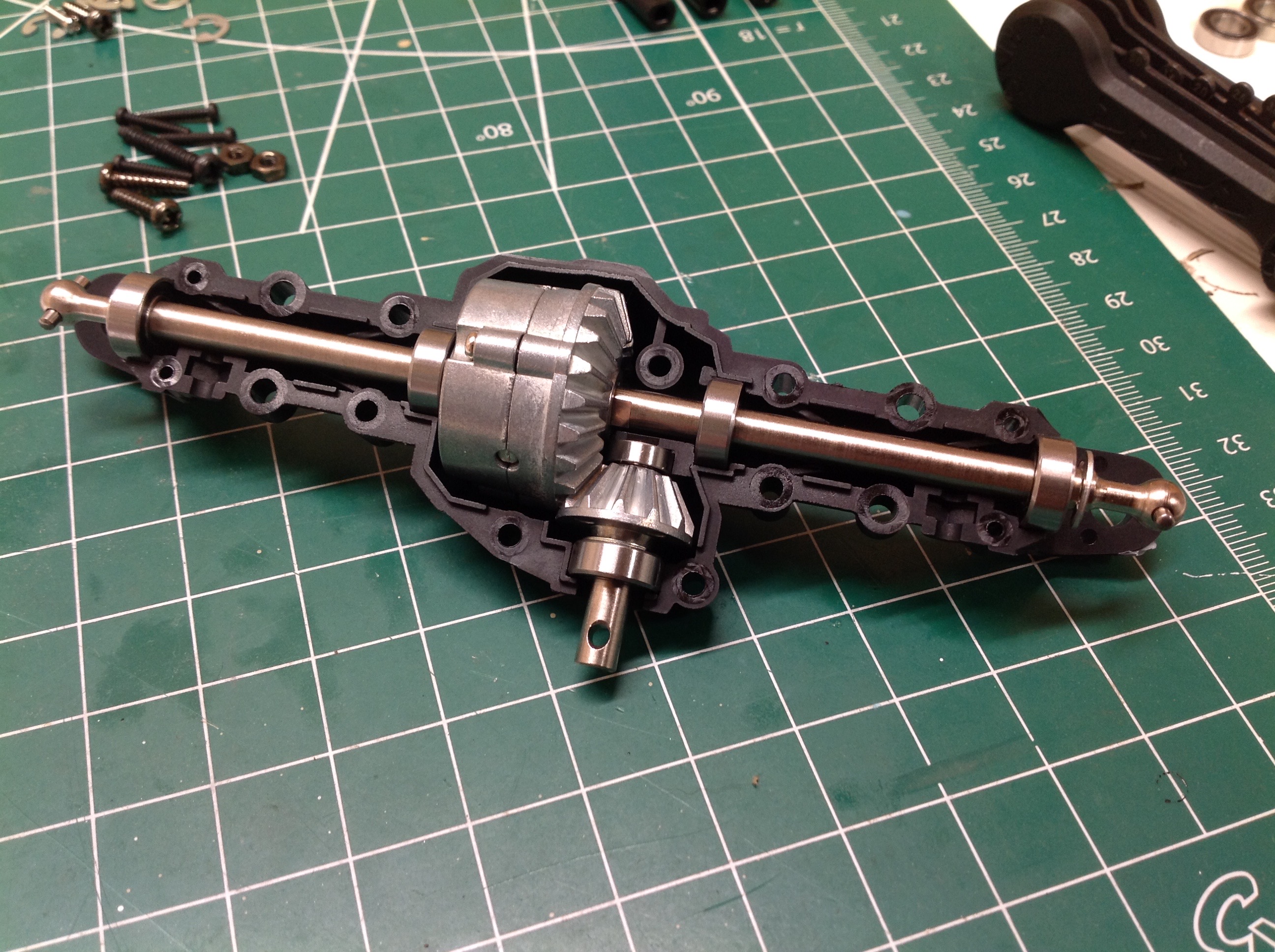
build. The axle housing is significant and rigid. There
should be no breakage here. The axles have dogbone ends, but
universals are available as an upgrade.
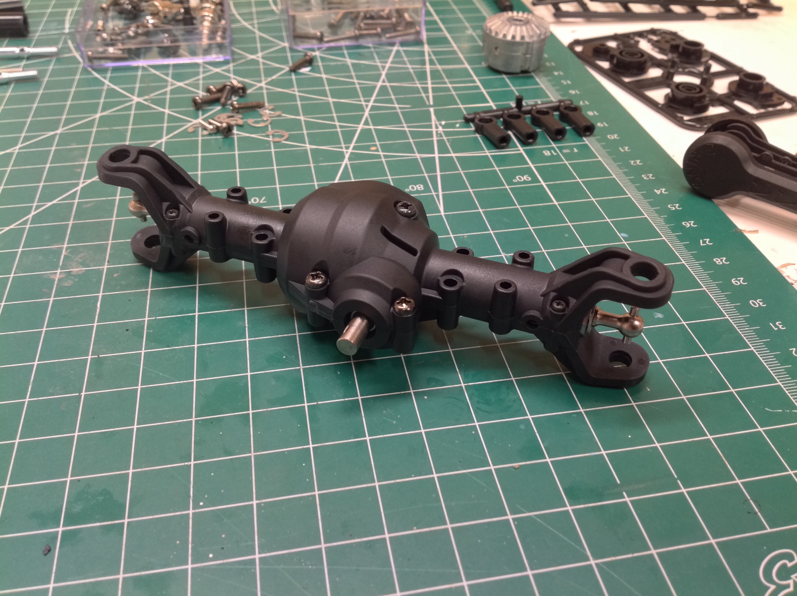
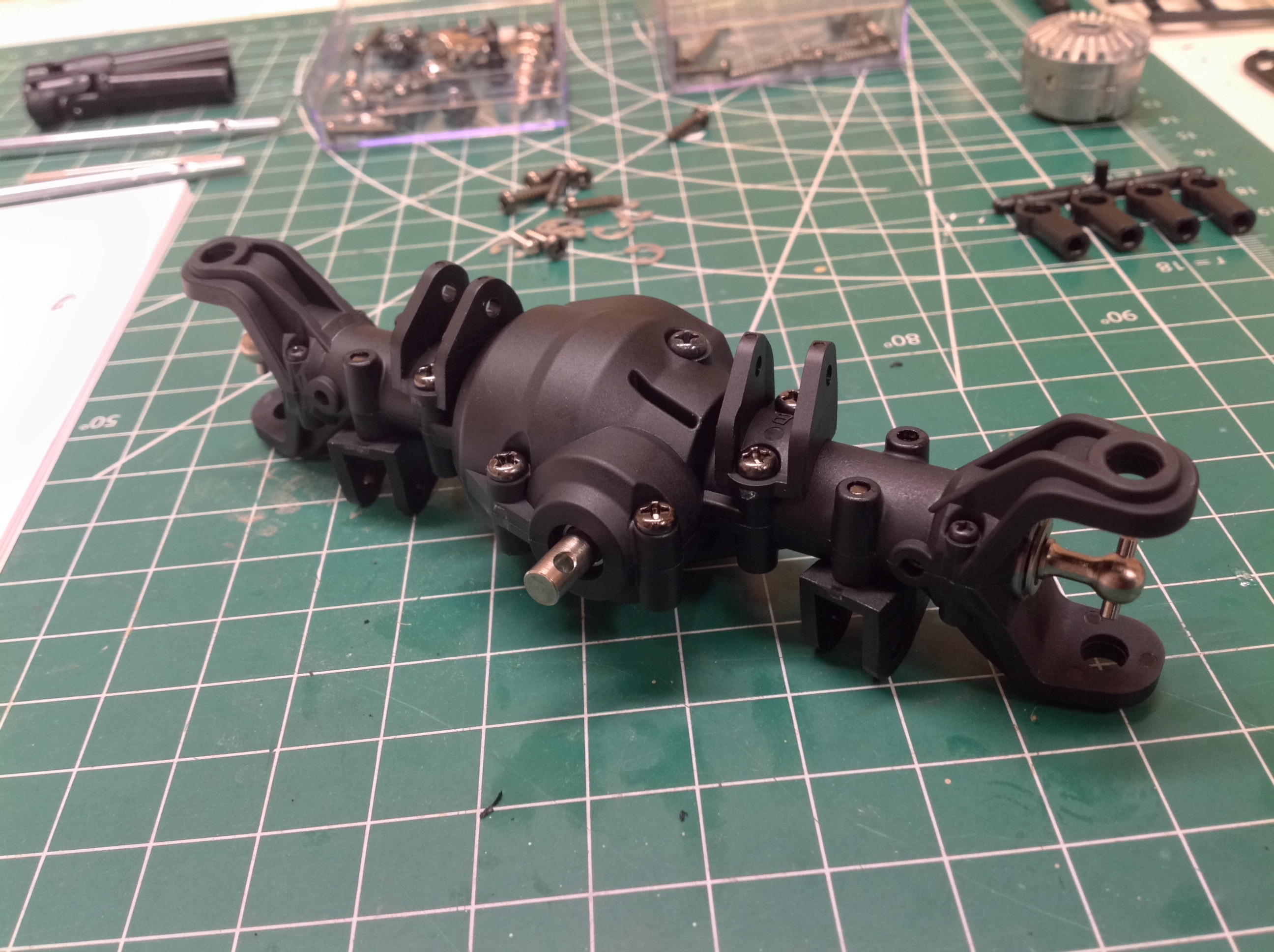
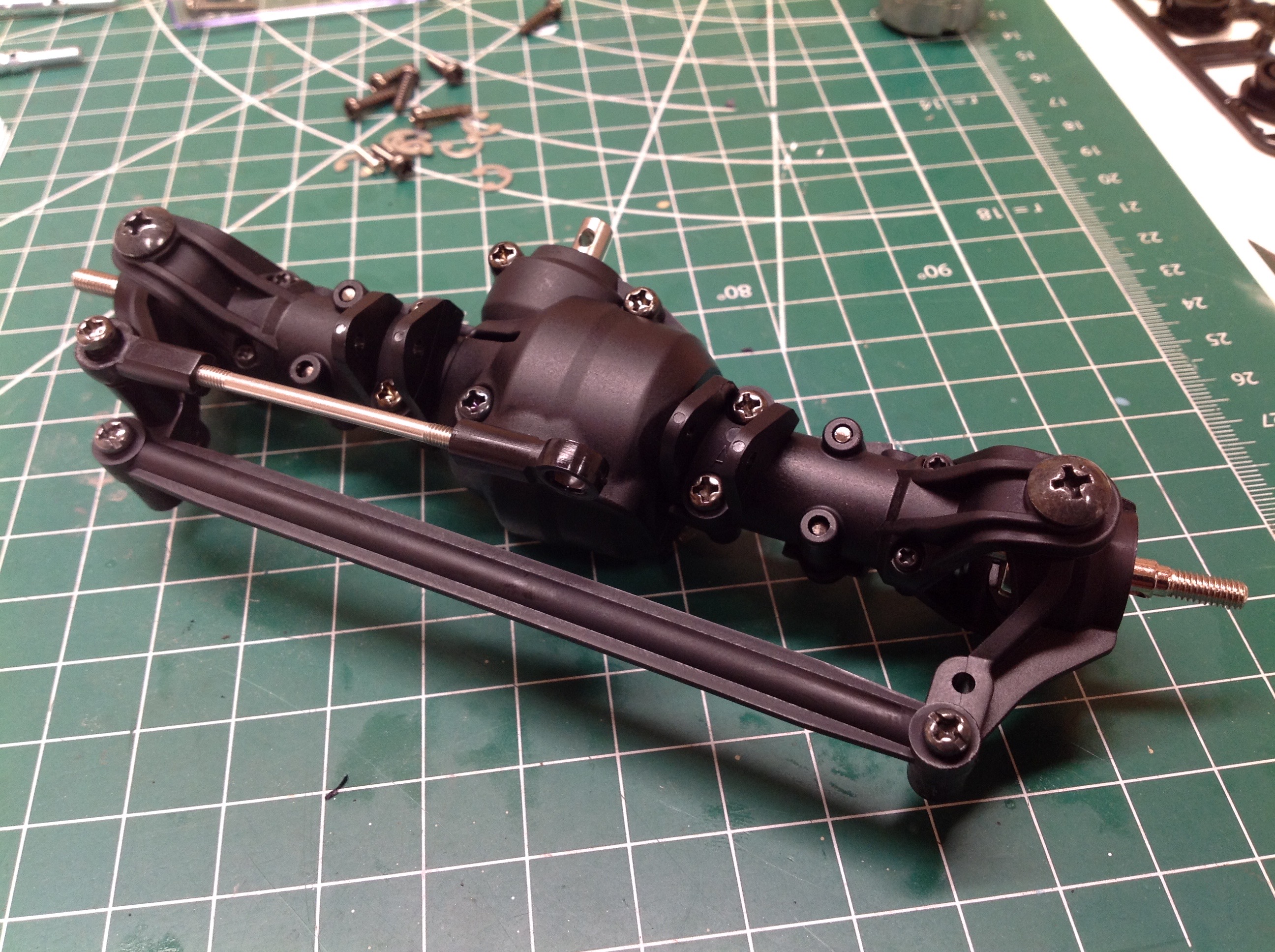
Here's the beefy front axle all buttoned up on the left. On the
right I've added the brackets for attaching the suspension links.
Now I can install the steering bits. The knuckles are one piece
plastic with no caster. The steering link is plastic and not
adjustable. The servo link is a metal rod with plastic rod ends
and balls. In the photo on the right you can see the suspension
links. Upper and lower links have different profiles but are all
plastic with no adjustability.
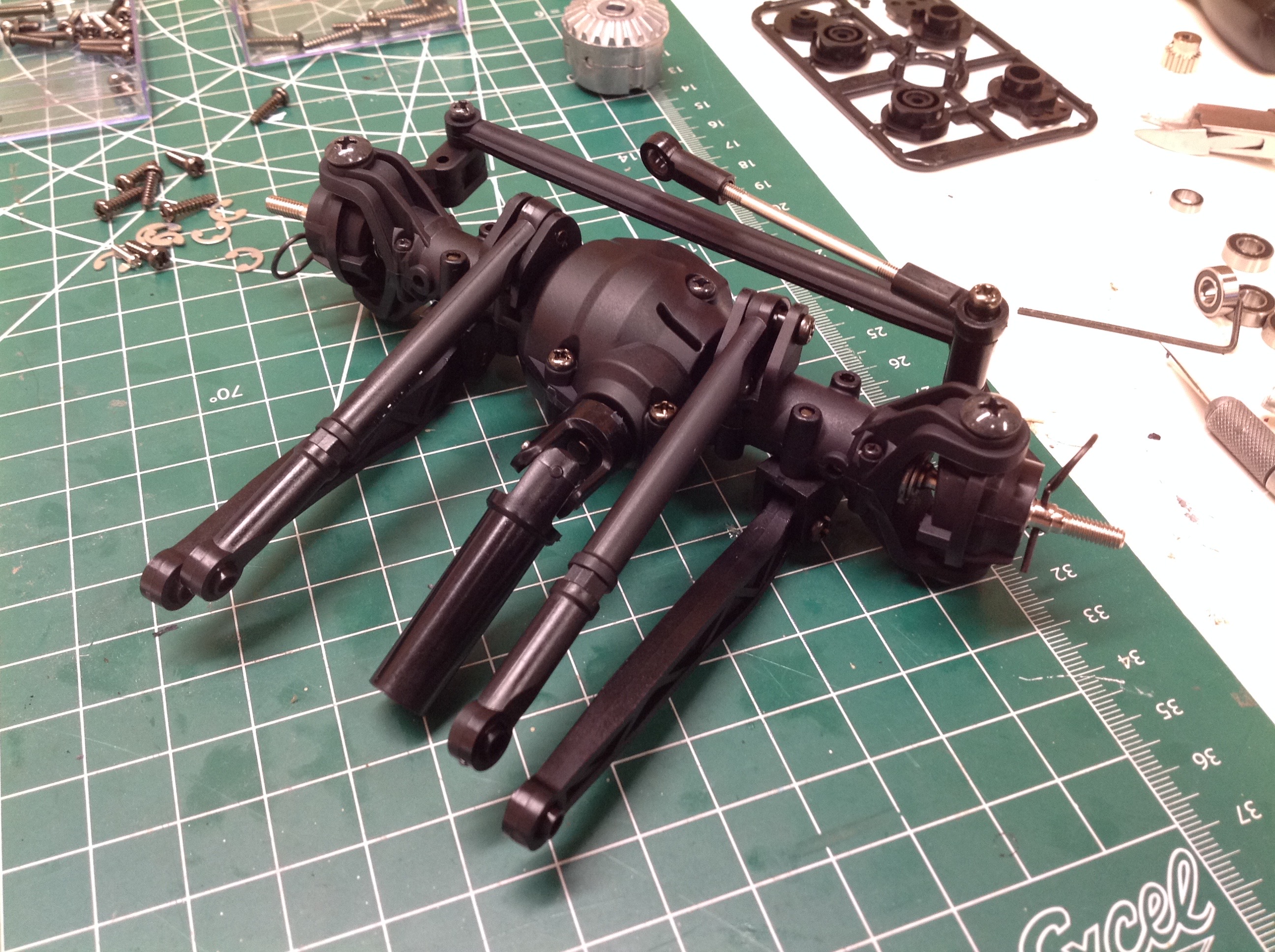
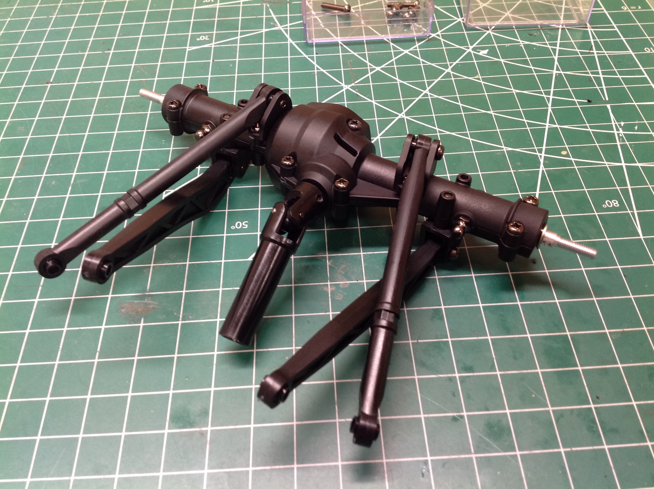
The rear axle is just a simplified version of the front without
steering. The differential is exactly the same, but the links are a
different length.
The brackets shown are used to attach the links to the chassis, and this
is where all the wheelbase adjustability comes in. You can see
that there are an extra set of holes for each bracket. These are
spaced at 10mm so they allow a shortening of the wheelbase by that
amount. You can also see that the link attachments are not
centered between the screws; they are actually offset by 5mm. This
means you can swap them left to right for 5mm adjustments. The
G-500 body uses a 267mm wheelbase, the second longest possible on this
chassis. The full list of options are: 242mm, 247mm, 252mm, 257mm,
262mm, 267mm, and 272mm. Note that different length links and
drive shafts would be required when changing wheelbase. There is
very little triangulation in the suspension, so it is almost more like
trailing arm than 4-link.
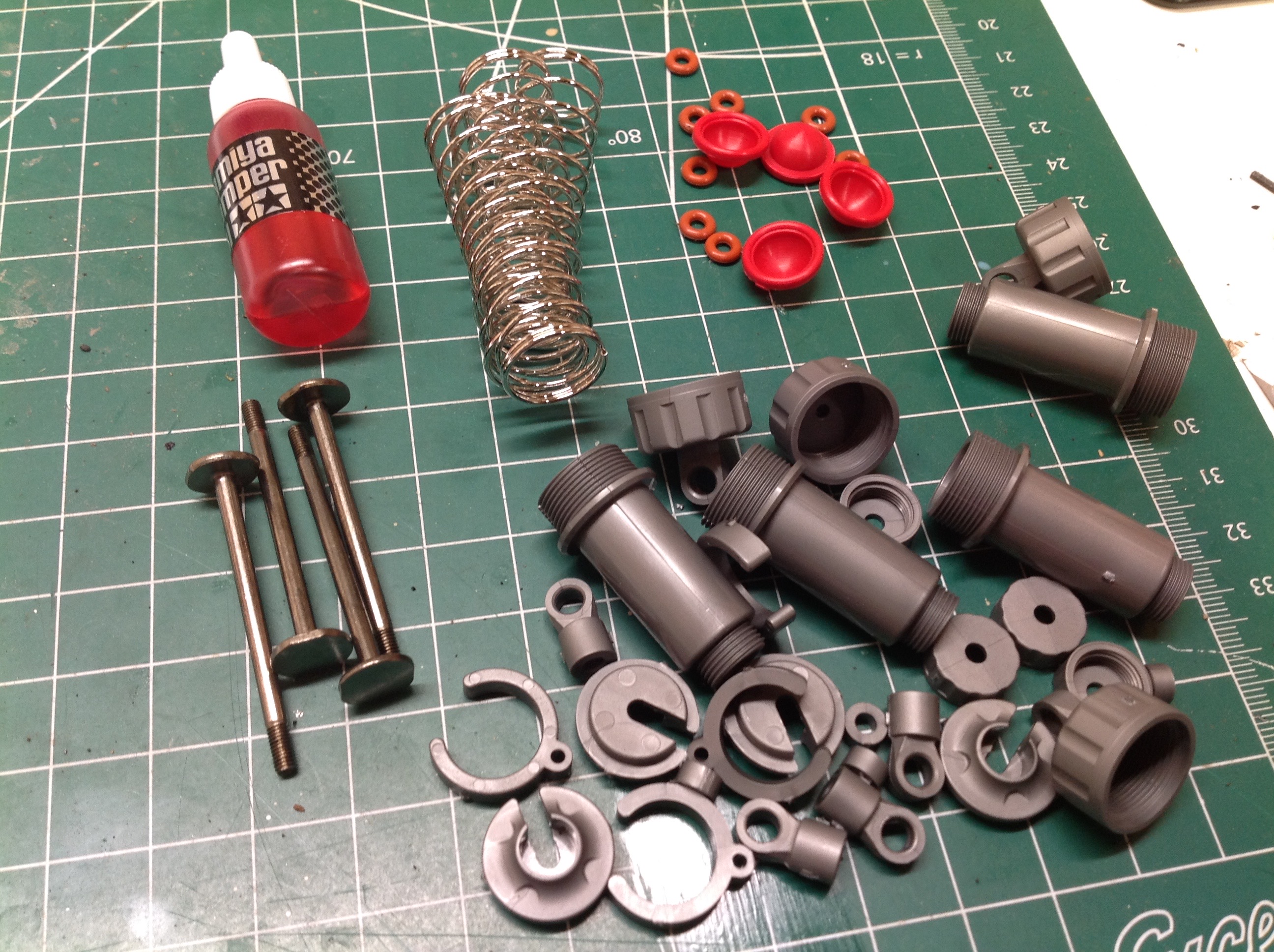
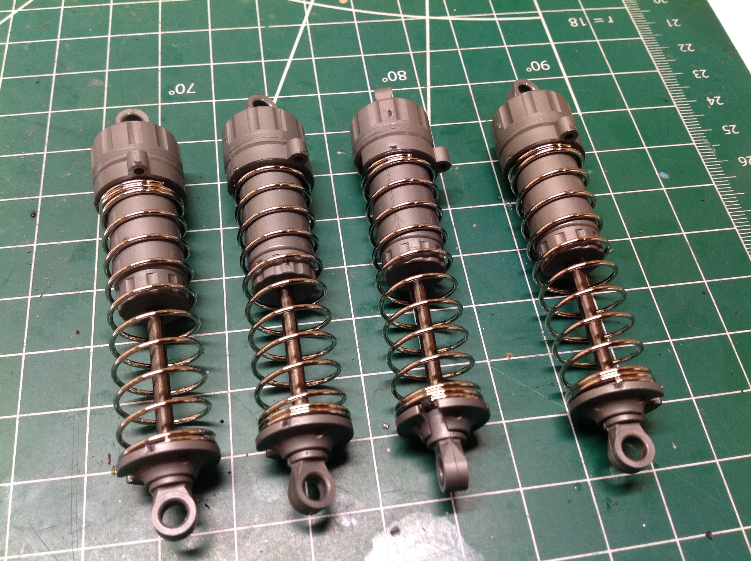
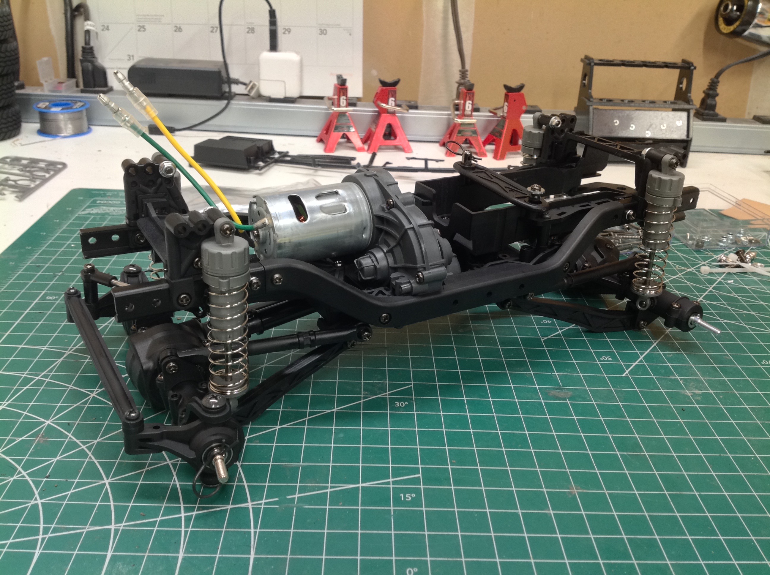
The gray oil shocks included are simplified CVAs with integrated pistons
just like the CC-01, but with a longer stroke. All four corners
use the same size. It is relatively unusual to see Tamiya include
the red damper oil with a kit. This is the softest (least viscous)
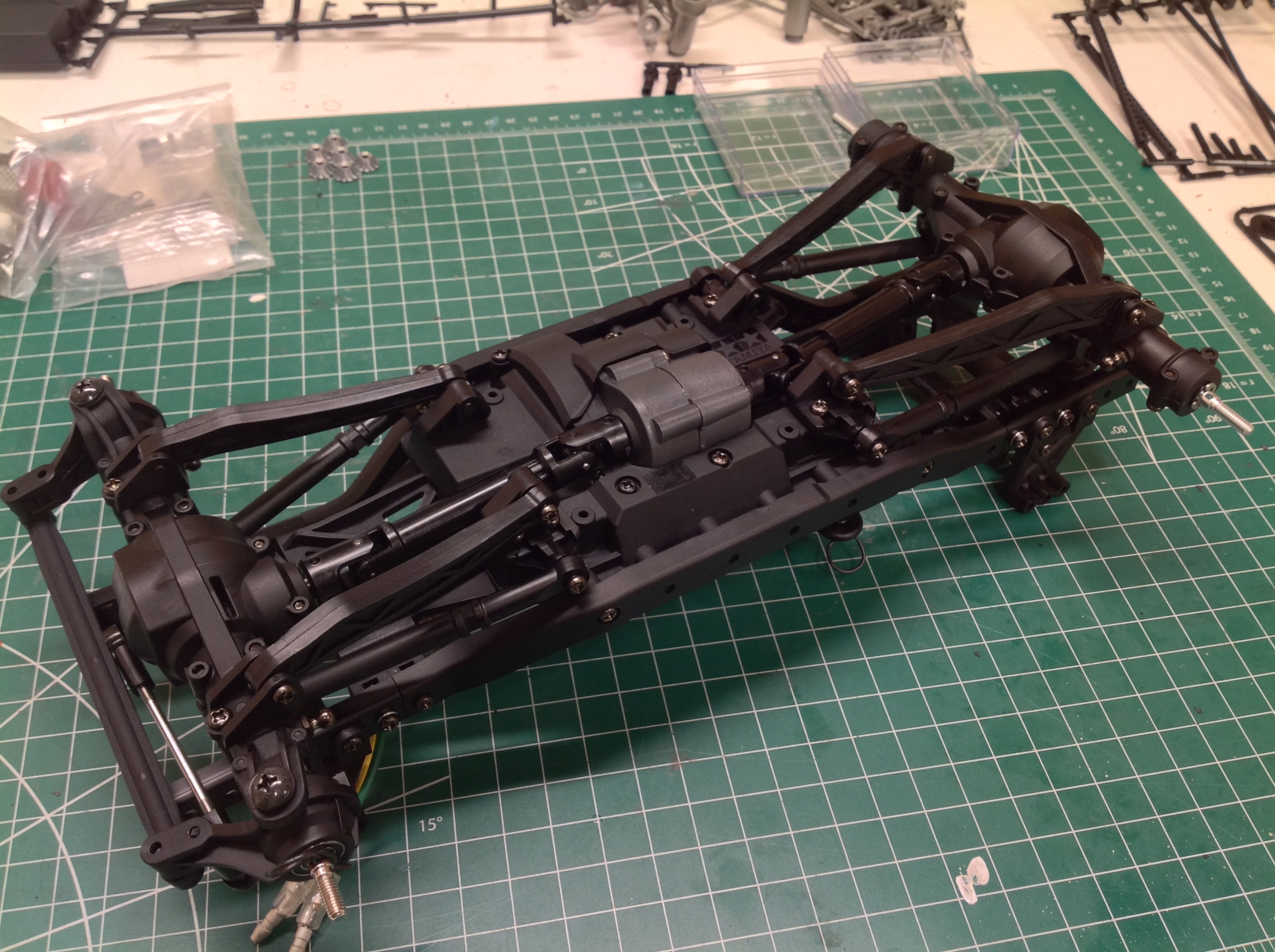
oil they make.
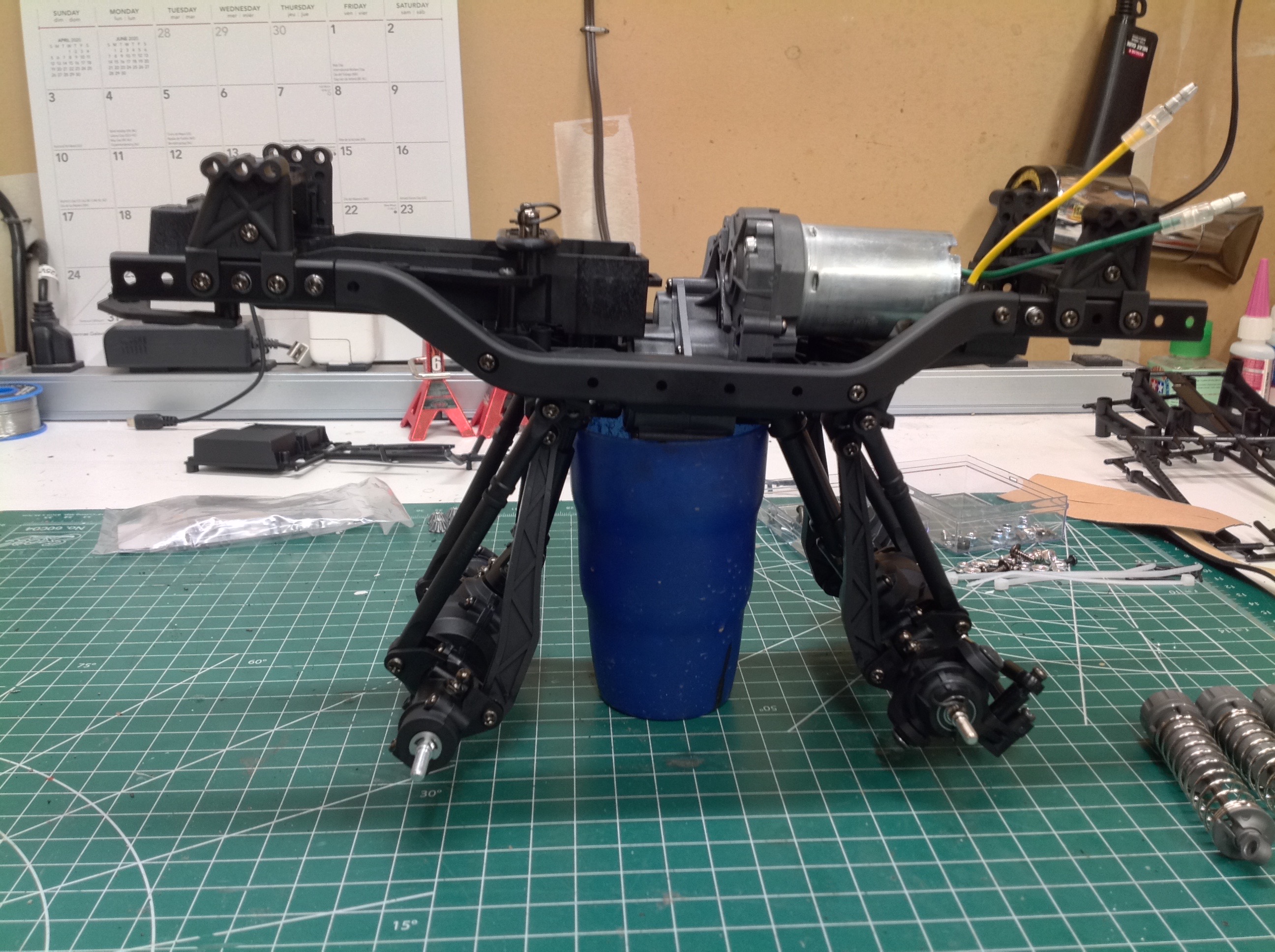
If you put on long enough shocks, you'd get a land strider look like this. U-joint angle might be a problem.
With the shocks installed the chassis is essentially complete.
Note that the shock diameter is vastly too large for scale (as is the
length), but this is a good thing for performance.
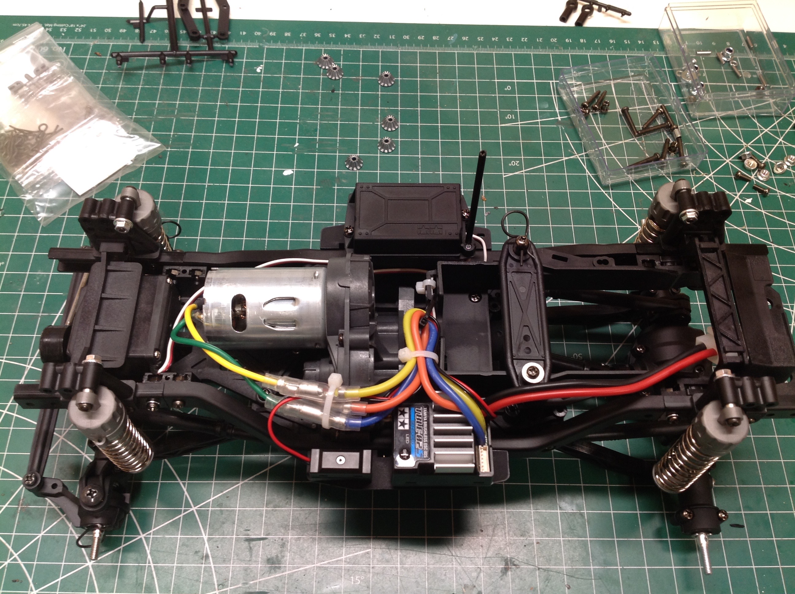
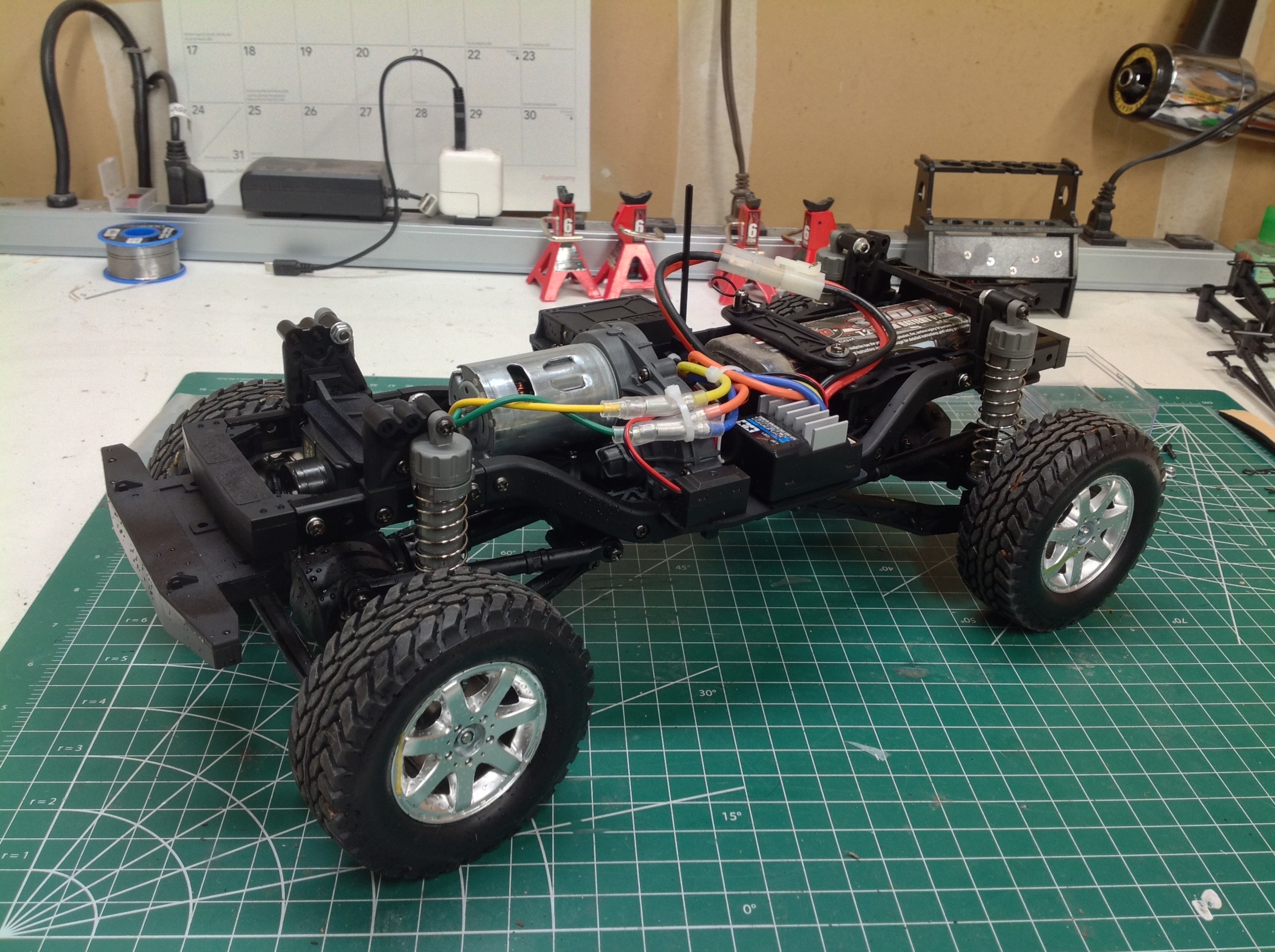
There is plenty of room to install the included TBLE-02s ESC and route
the wires neatly as shown on the left. Installation of the wheels
and tires completes the rolling chassis which is now fully driveable.
©2020 Eric Albrecht