MST CFX-W Project
Page 1: Chassis Construction
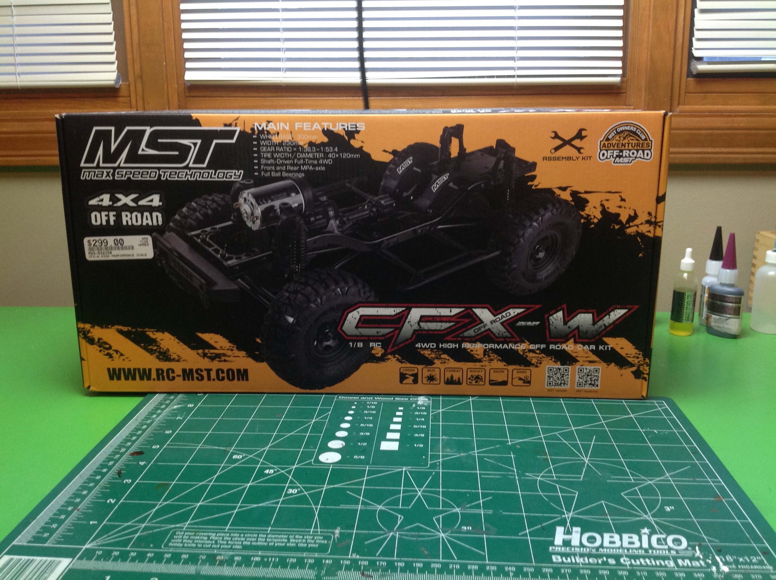
The box is not particularly large since it is only a chassis divided up
into small parts. I thought this price was pretty good for what
you get. Let's see if I was right.
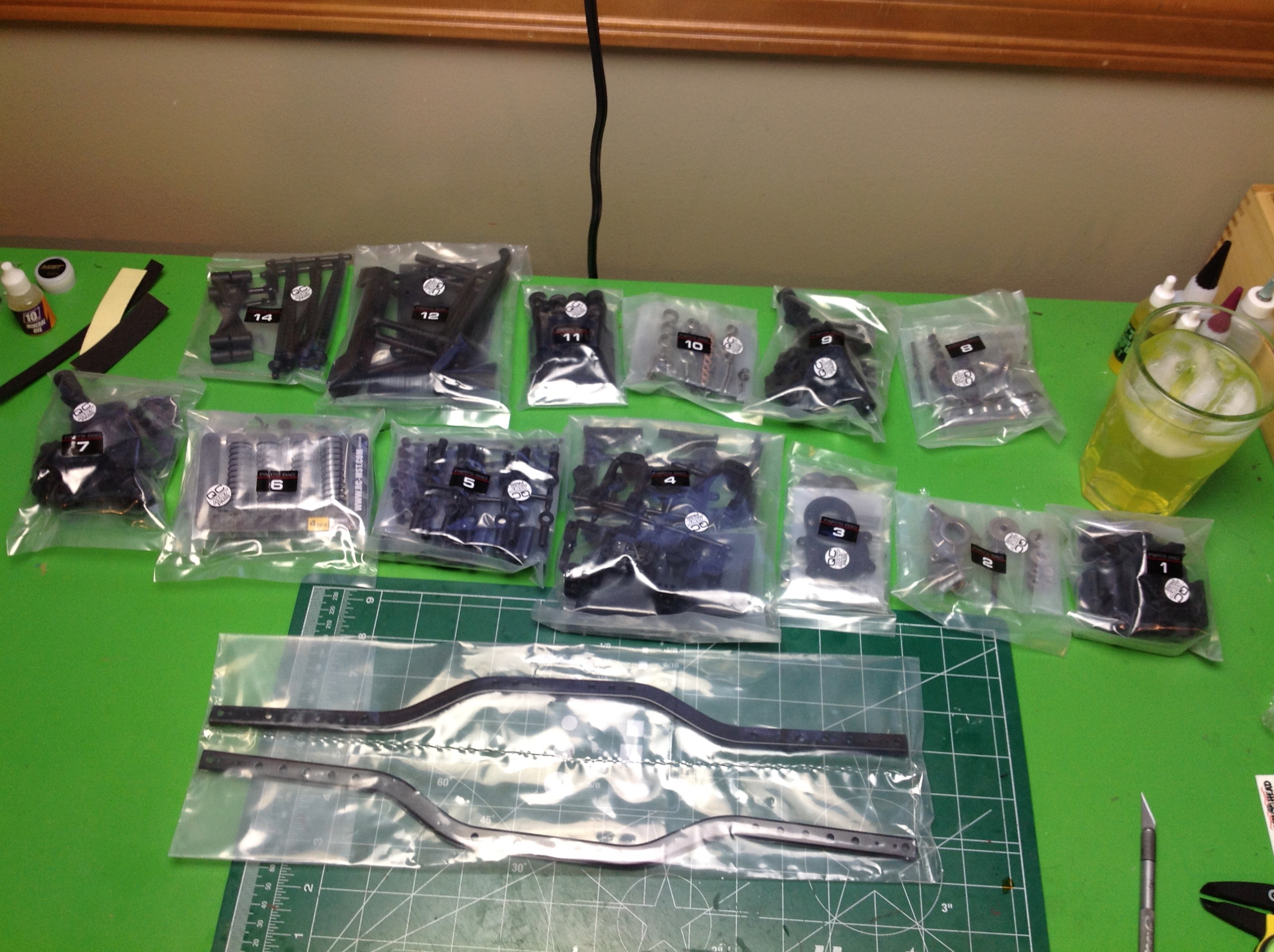
Inside the box you can see individually numbered bags up to 14.
13,
not shown, is the wheels and tires. Dividing up the build like
this
makes it very easy to follow everything. The chassis rails are
bagged
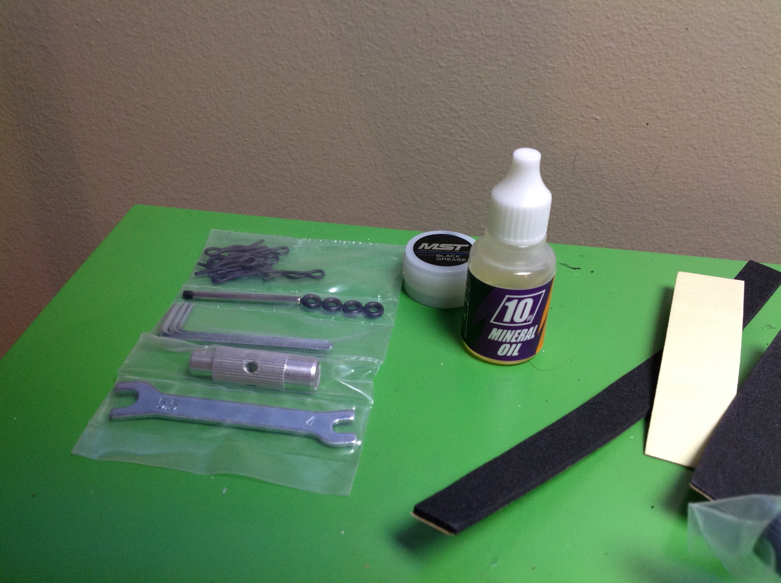
on their own. The selection of tools that comes with the set is a
little unusual. There is a turnbuckle wrench, but the cross wrench
uses a cross bar instead of being one cast part. There is also
some black grease and some mineral oil for shock oil. This is
about as cheap as you could go for shock oil, but then the shocks aren't
very good anyway. There is also some servo tape and some foam
strips.
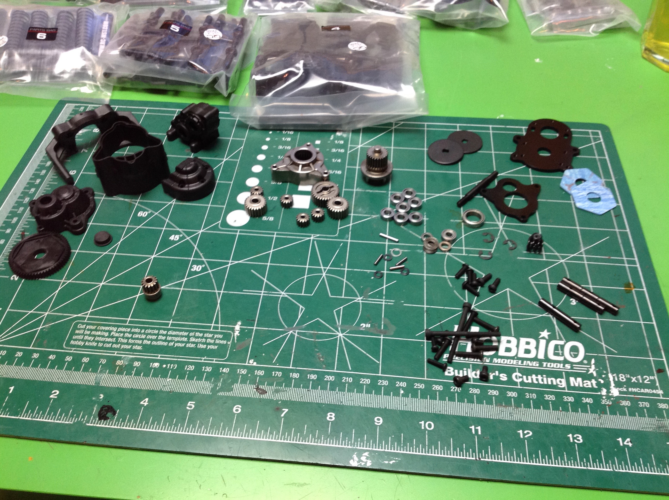
You would think that each bag would go with a step, or perhaps there
would be multiple steps per bag. Actually, it is the other way
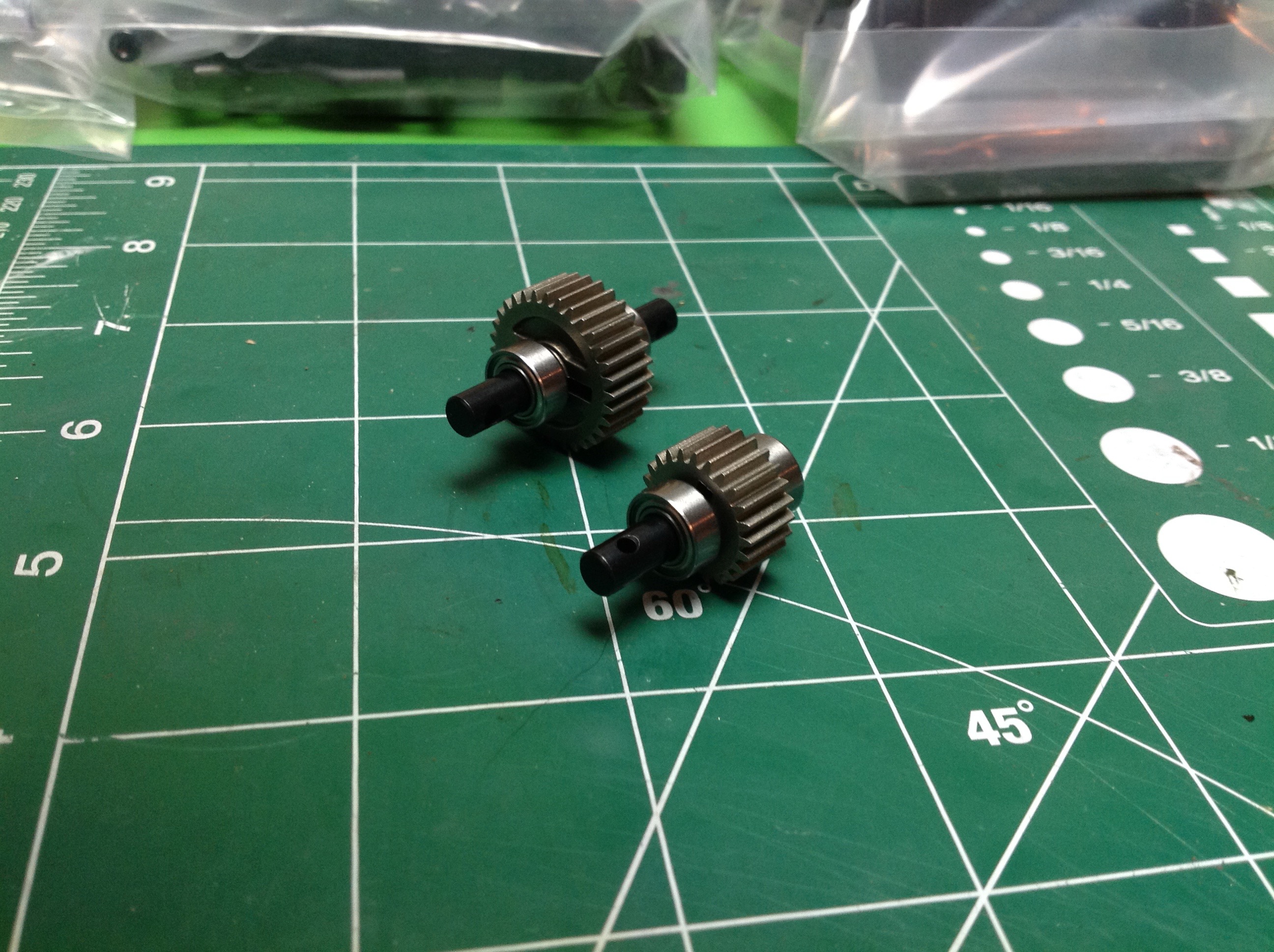
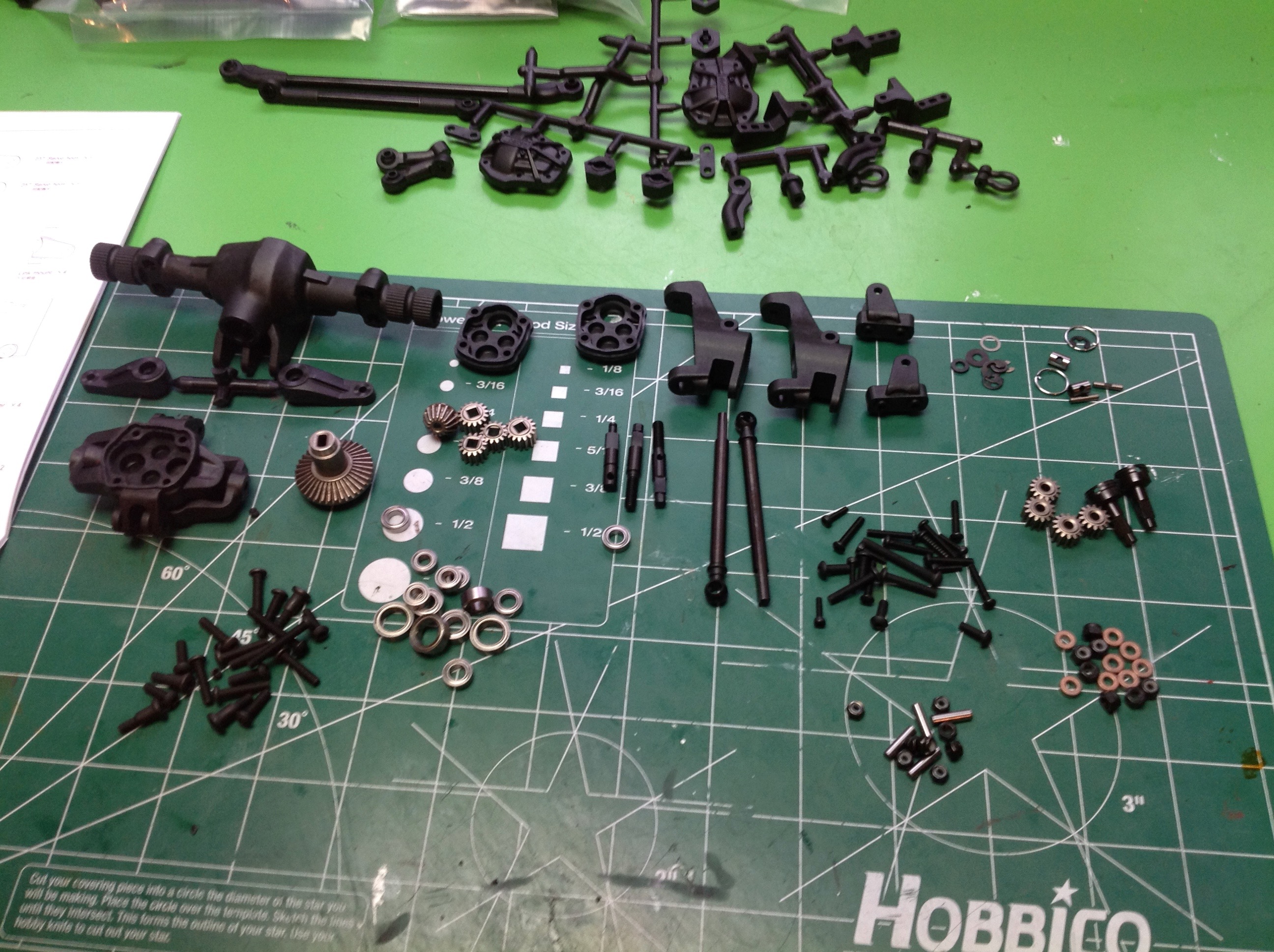
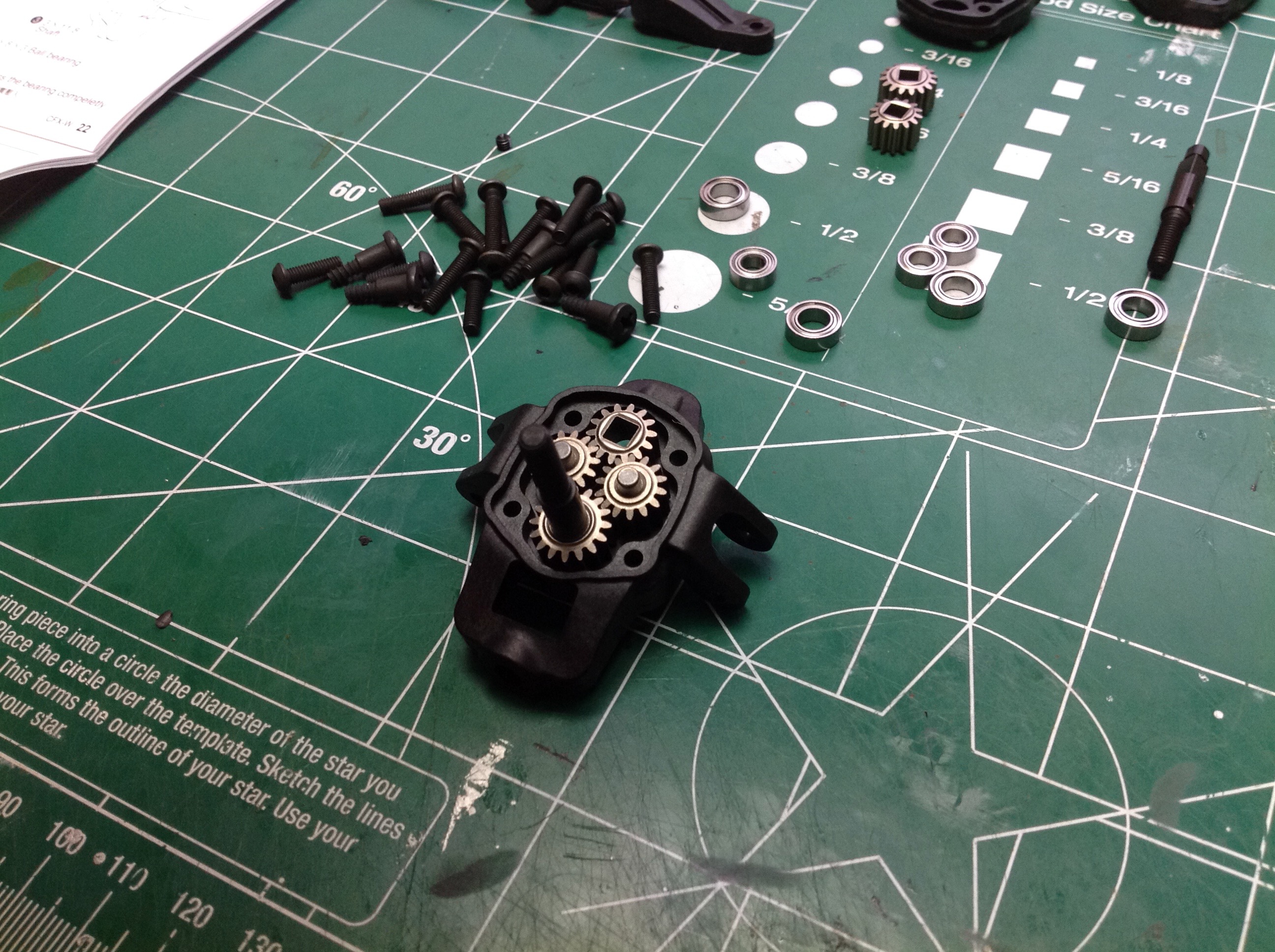
around. Step 1 requires you to open bags 1-3. Those parts
are shown in the left hand image. Feast your eyes on all those
metal gears! The kit also includes a full set of ball
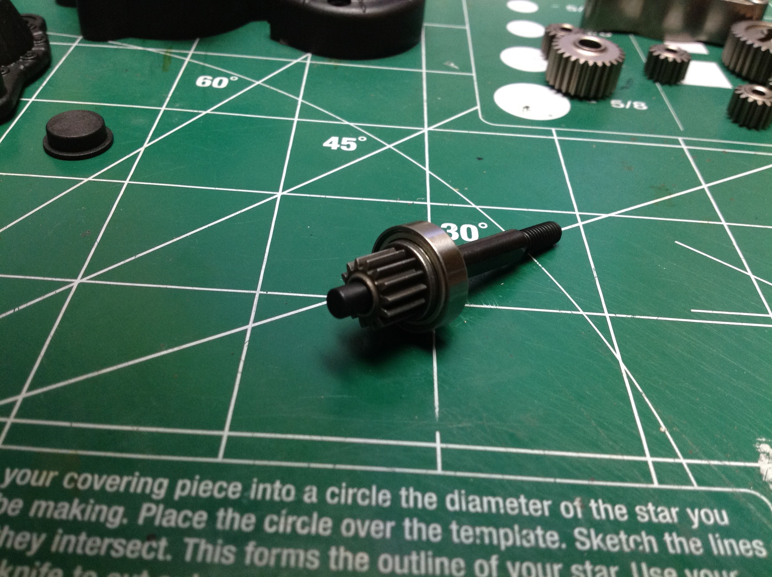
bearings. The build starts with the transmission, and the
transmission starts with the sun gear shaft for the planetary gear
set. The other end of this shaft will be the motor spur gear. The sun gear has 14 teeth.
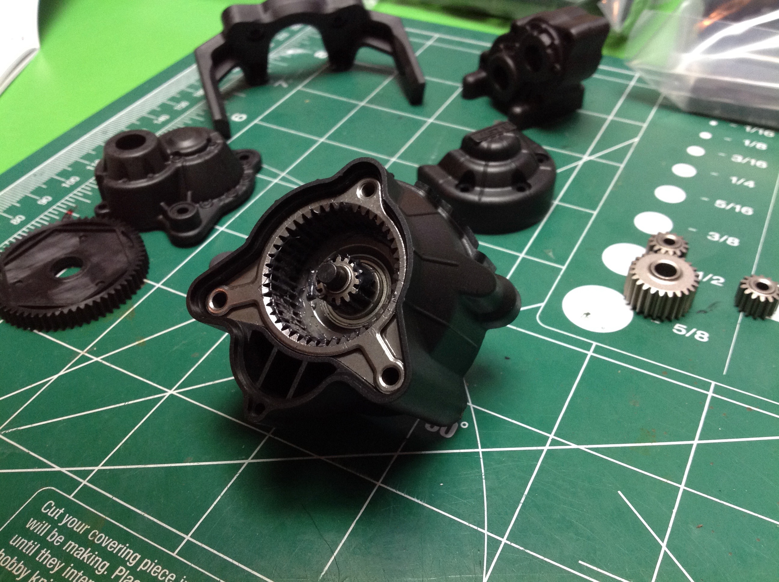
Next comes the 42 tooth metal ring gear which sits in a mostly
triangular slot in a plastic housing. The right hand image shows
the planet carrier. Each planet gear has 14 teeth. The
output gear is attached to the carrier and has 24 teeth. The
reduction of the planetary gear set is therefore 4:1 in a single
stage.
- Planetary Ratio = 1+(42/14) = 4:1
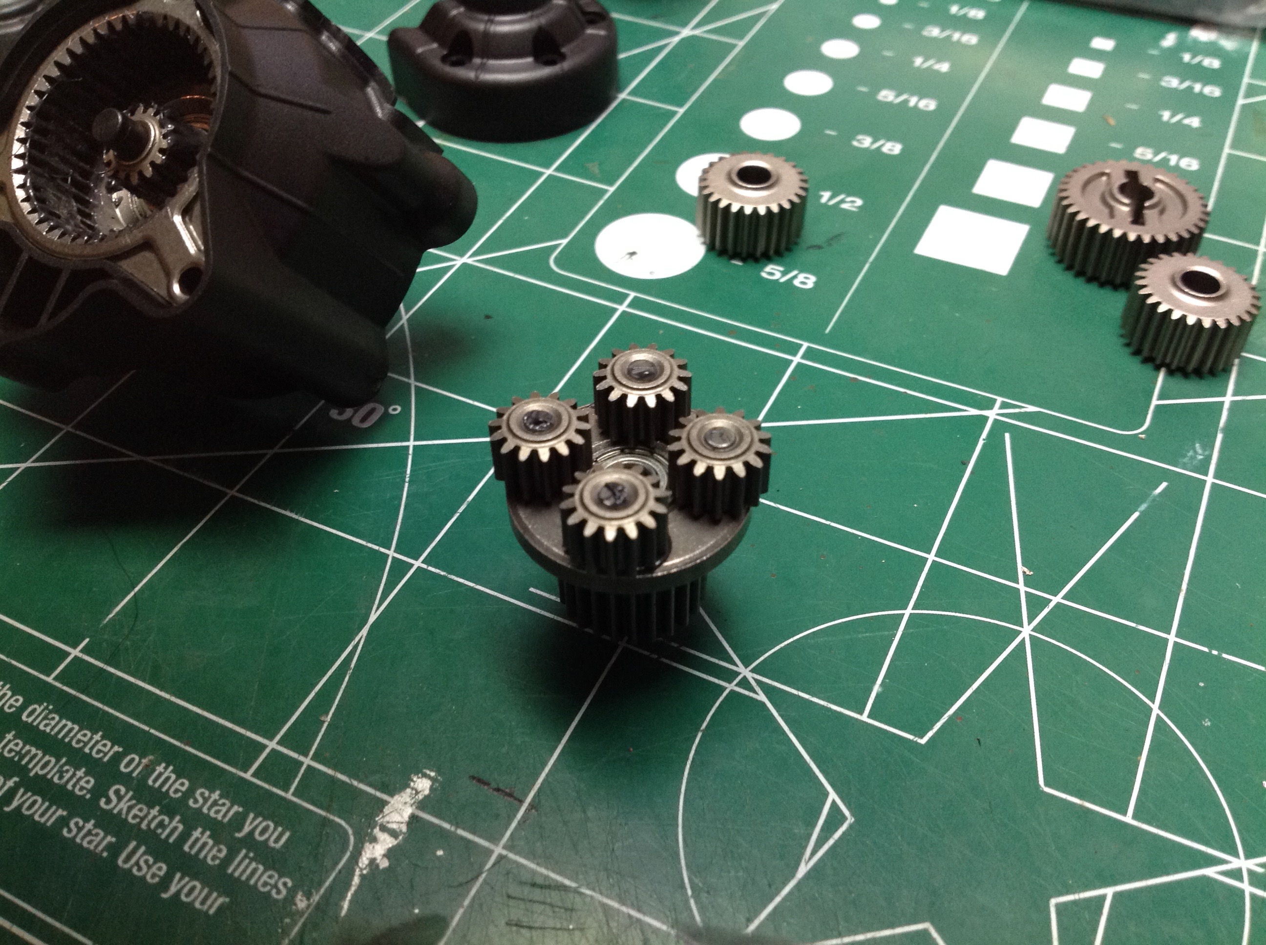
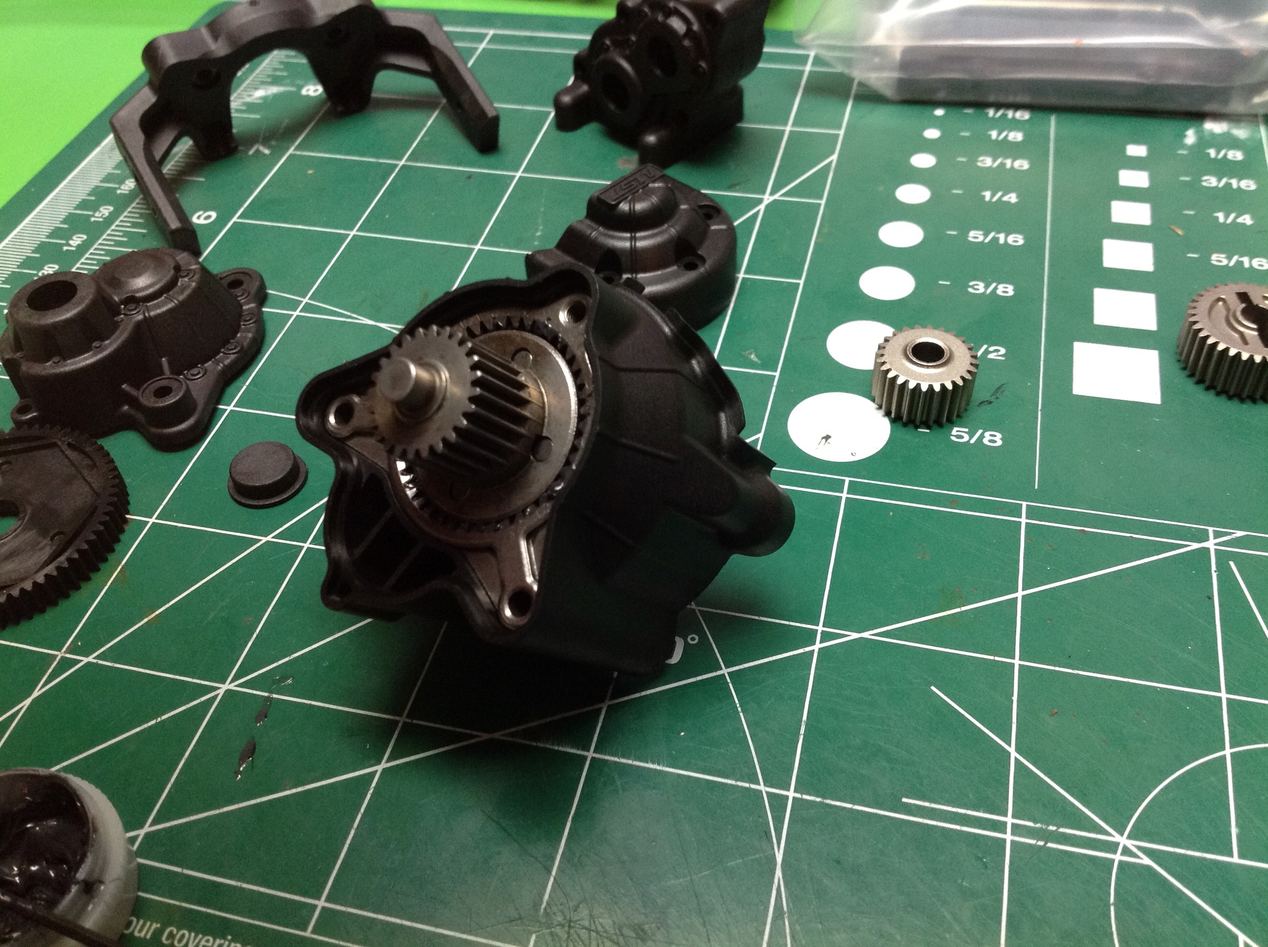
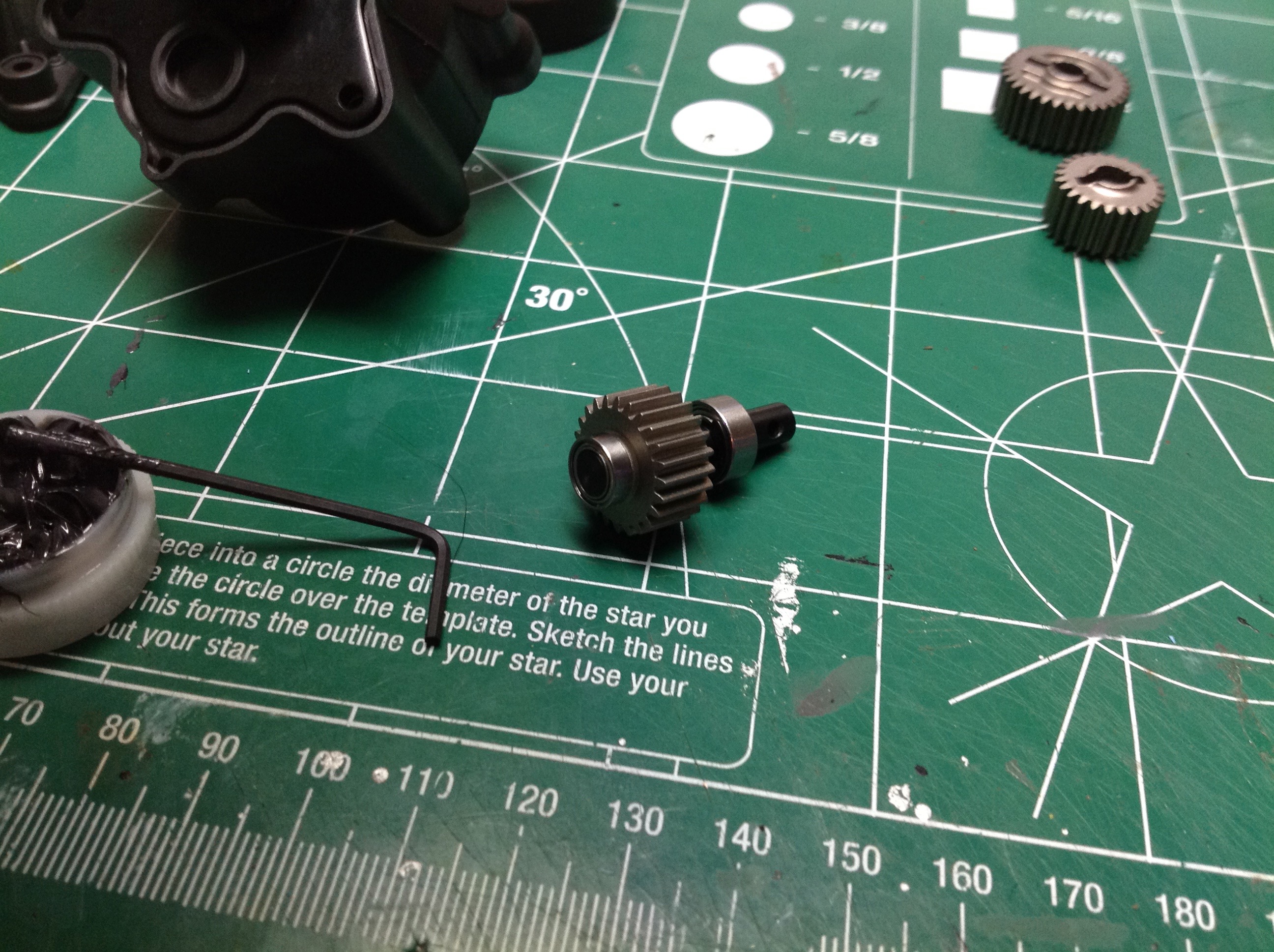
The left hand image shows the installed carrier which hides the
planetary gear set behind it. We're not done yet though.
There is one more gear shaft. This gear has 24 teeth just like the
planetary output so there is no reduction here. It serves to
reverse the direction of rotation and also to put the final output below
the main axis.
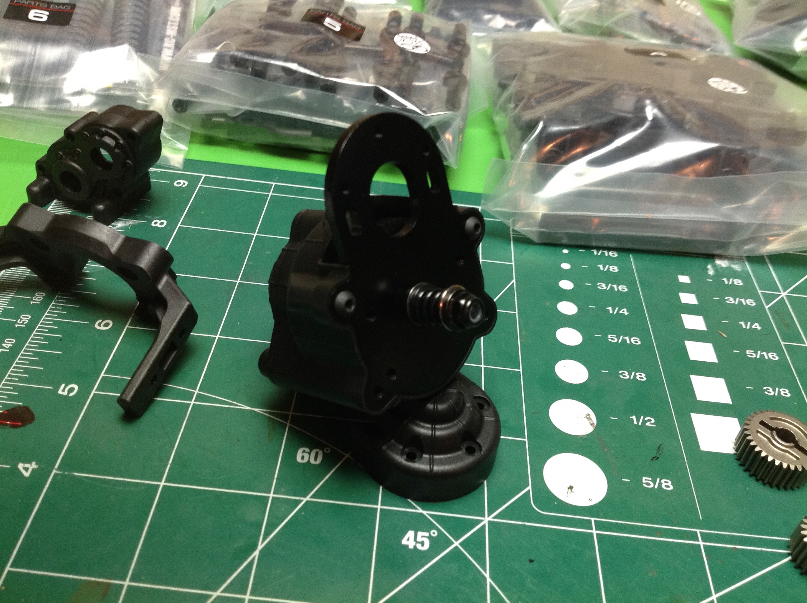
Time to button up the transmission. You wouldn't know all that
metal goodness was inside, but this is a pretty impressive transmission
as well as nearly bulletproof. It should handle any torque you can
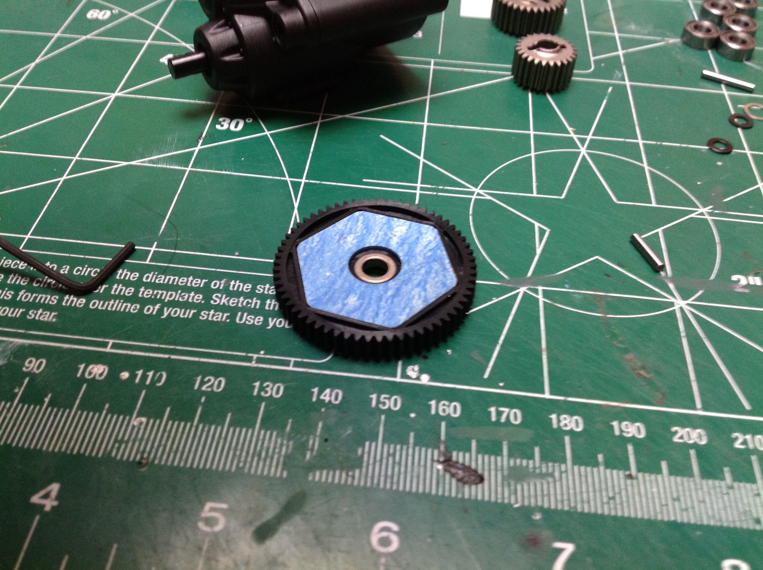
throw at it. With that in mind, we're going to need a slipper
clutch. The clutch is built into the spur gear as shown. It
has friction pads on both sides.
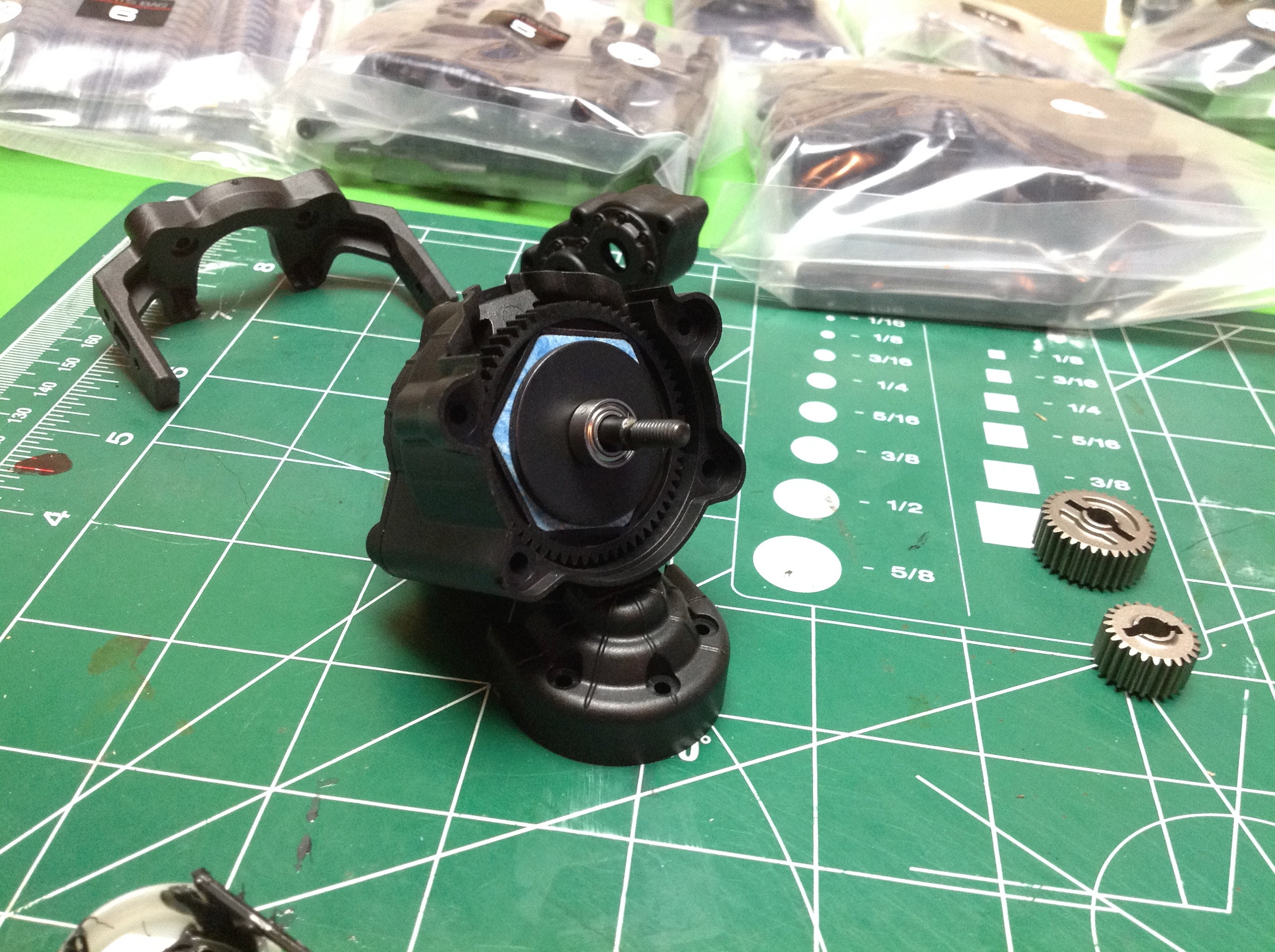
The slipper/spur setup is nestled into the transmission assembly and
then covered with the motor mounting plate. The spring to adjust
the slip torque is on the outside of this. Notice how little space
the entire transmission takes.
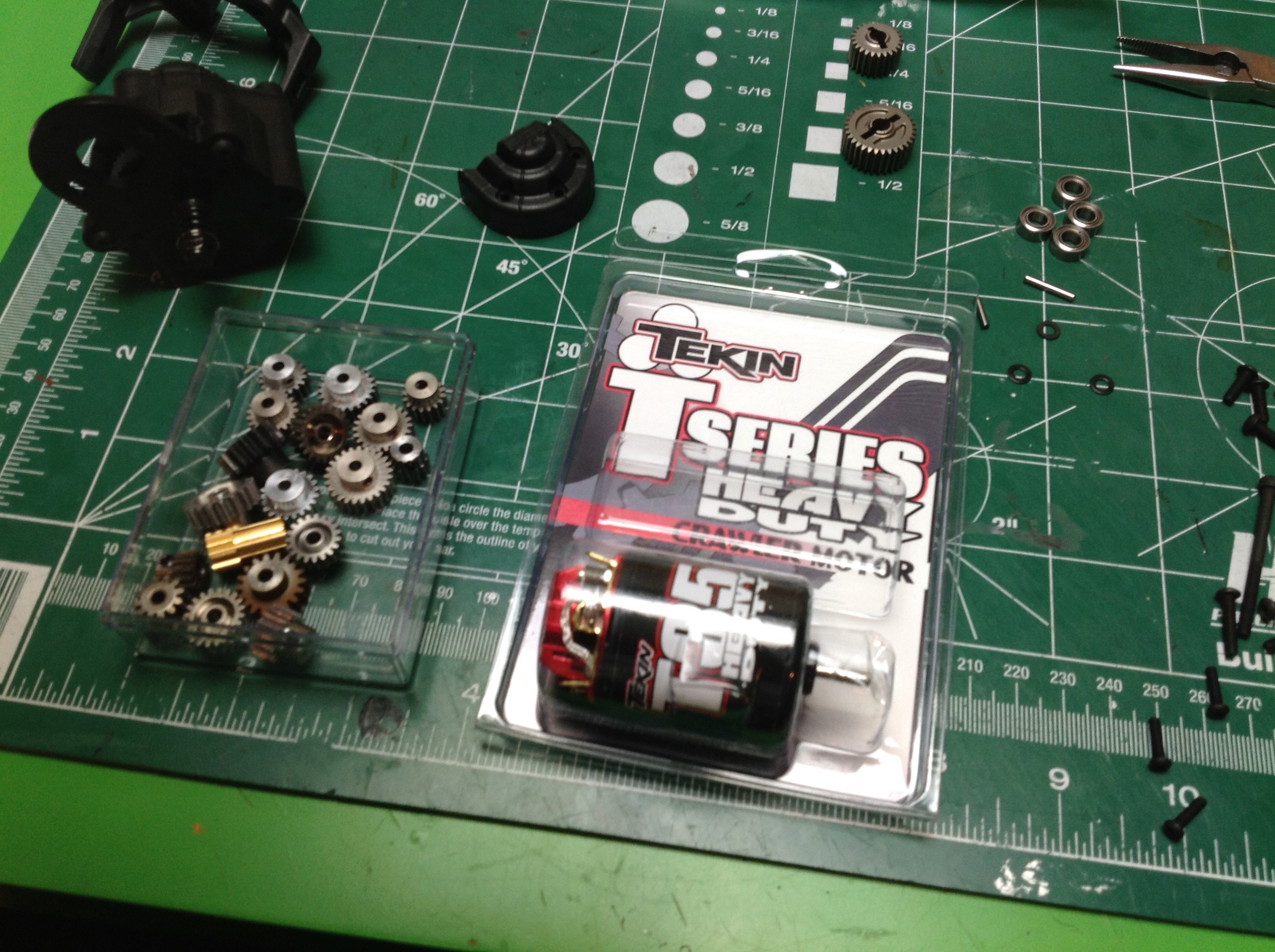
I wanted a good quality brushed motor for this model so I went with a
Tekin 35 turn which has been excellent. The kit actually did not
come with a pinion gear, just a chart telling you the different gear
ratios you get using from 17 to 25 teeth. Luckily I've got a
pretty good collection of spares.
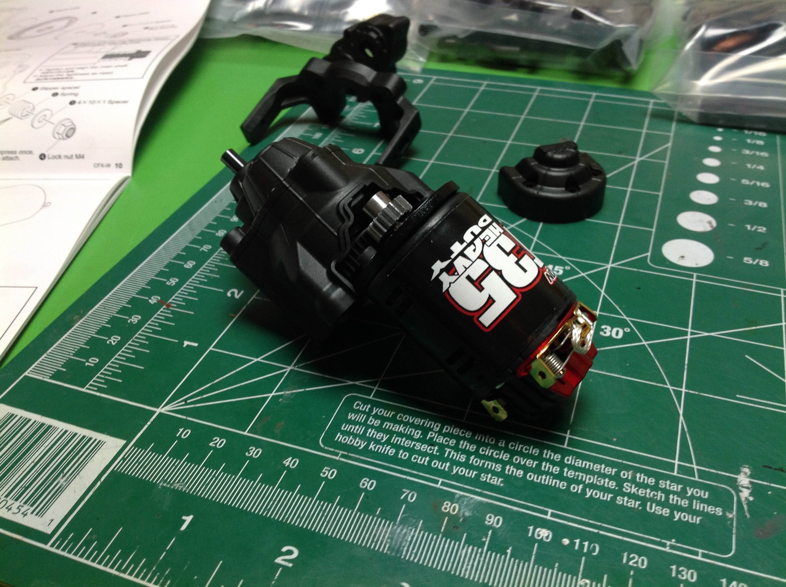
Once the gear mesh is set, the motor can be tightened and the gear cover
installed. Now the transmission is complete. It is
remarkably compact unit for how much is going on inside. The final
bits shown in the right hand image are the mounting arms which will
attach to the chassis rails. This was all part of Step 1 which had
11 substeps.
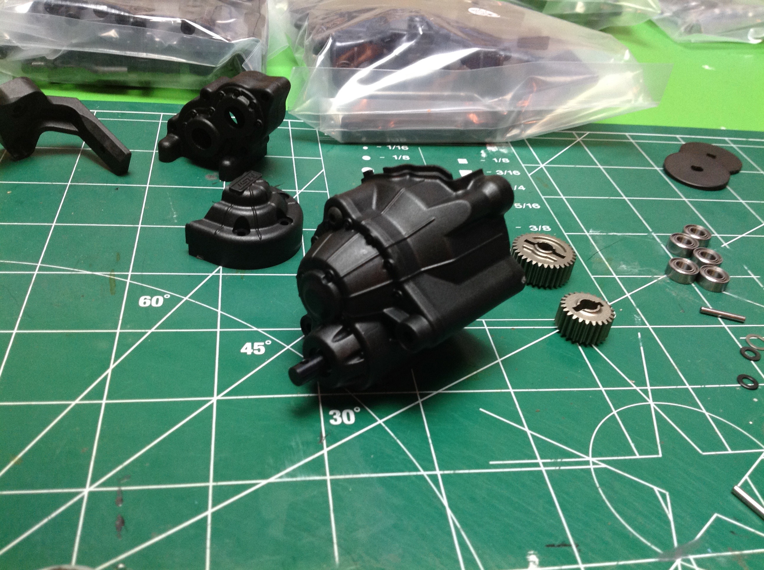
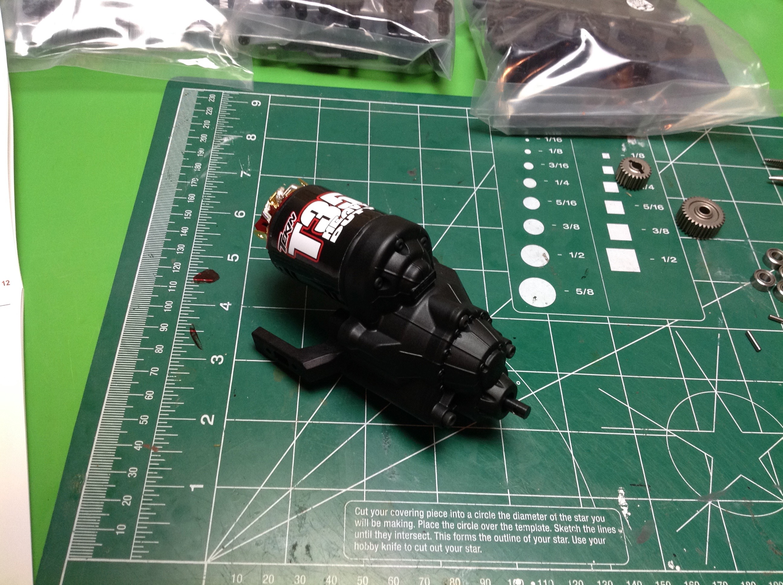
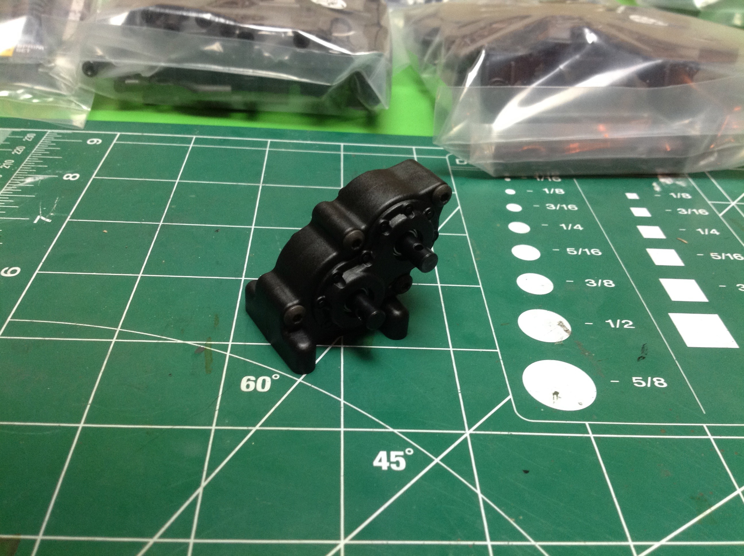
Step 2 is much quicker: building the transfer case. The t-case
reverses the direction of rotation, drops the output down to a lower
level, and performs a further 32:24 = 1.33:1 reduction. Again, all
the gears are metal and every shaft is supported with ball bearings.
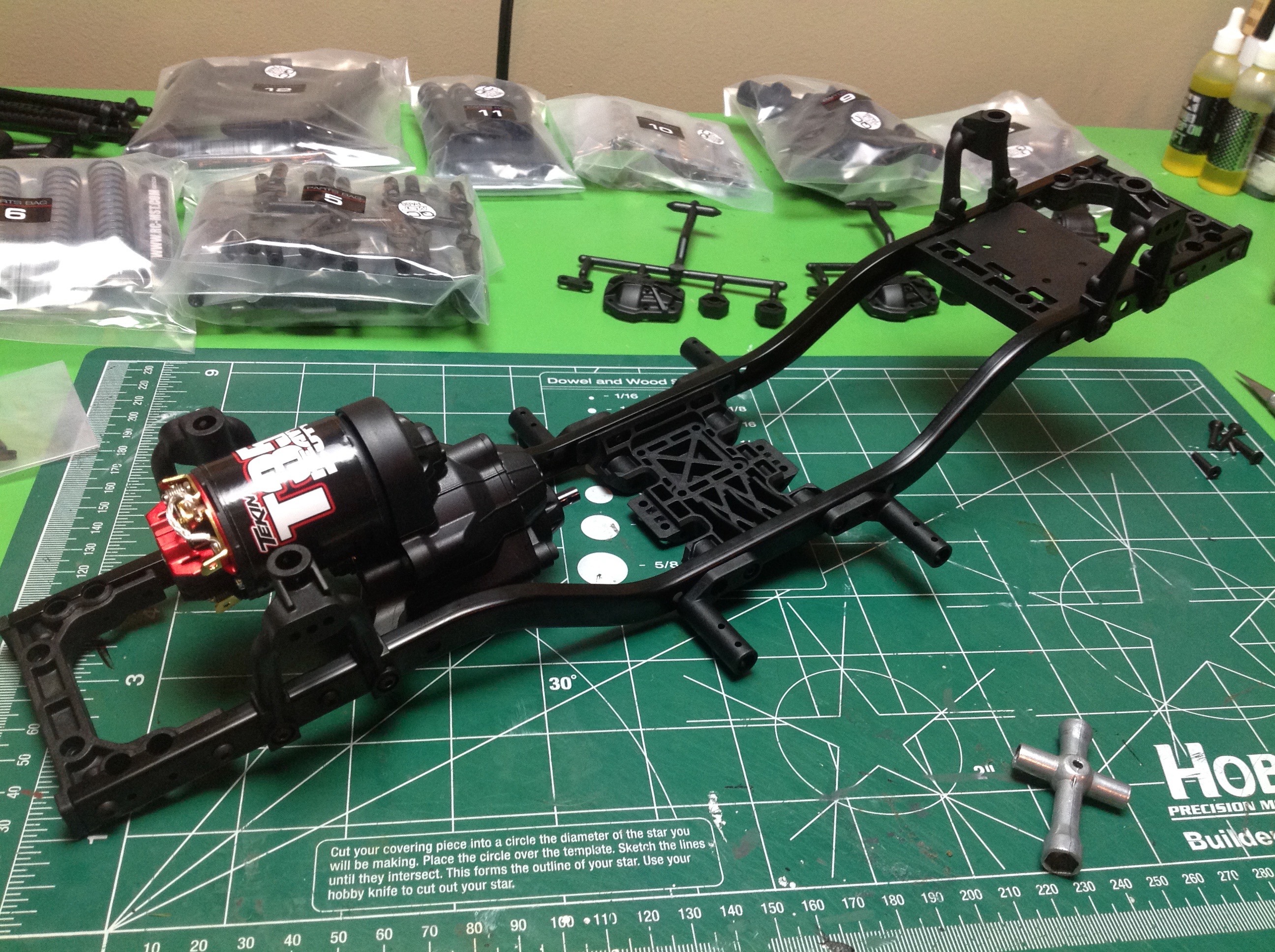
Here's another instructions oddity. Having finished with bags 1,
2, and 3 in Steps 1 and 2, now Step 3 uses bags 4 and 14. Why skip
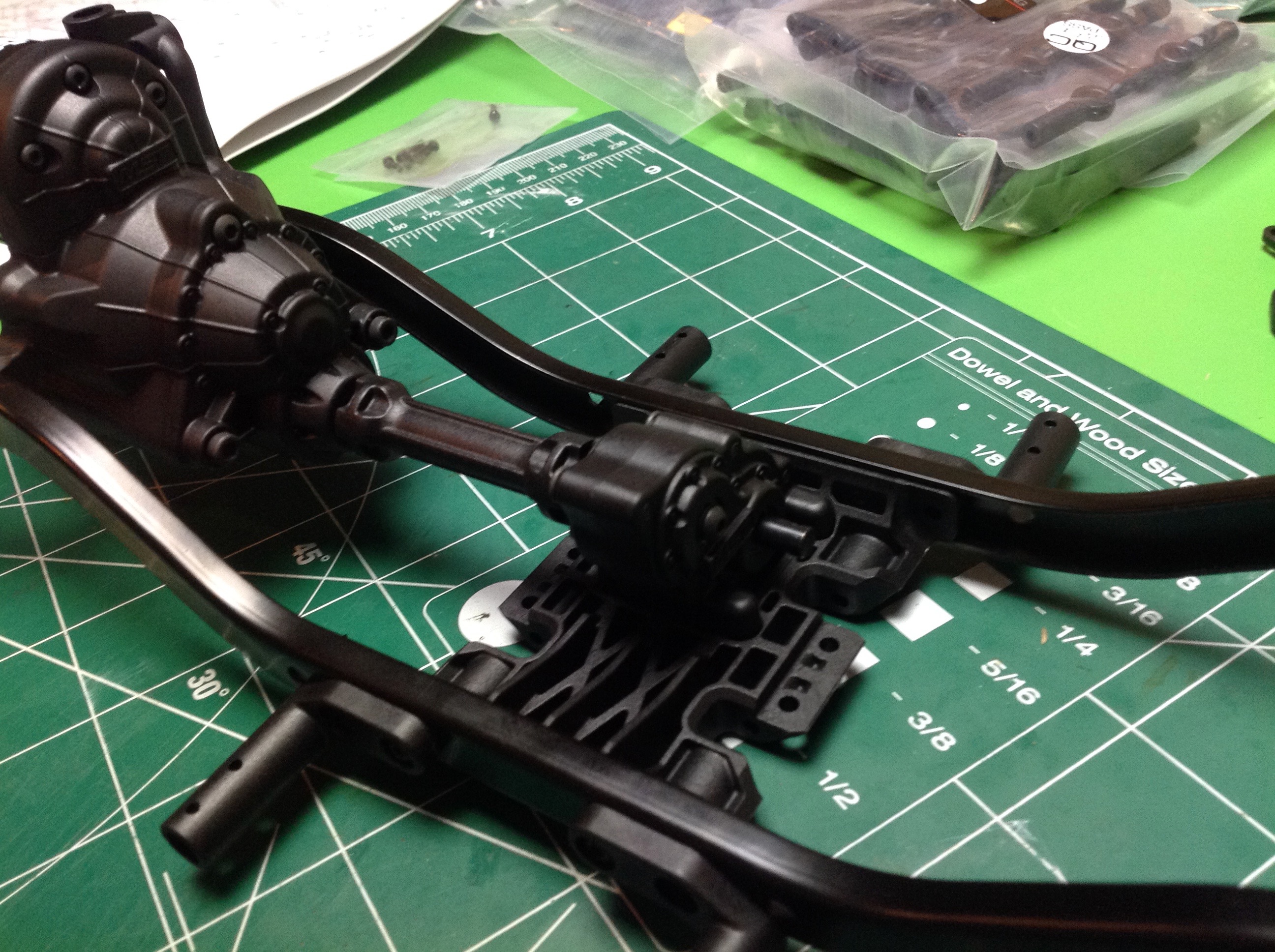
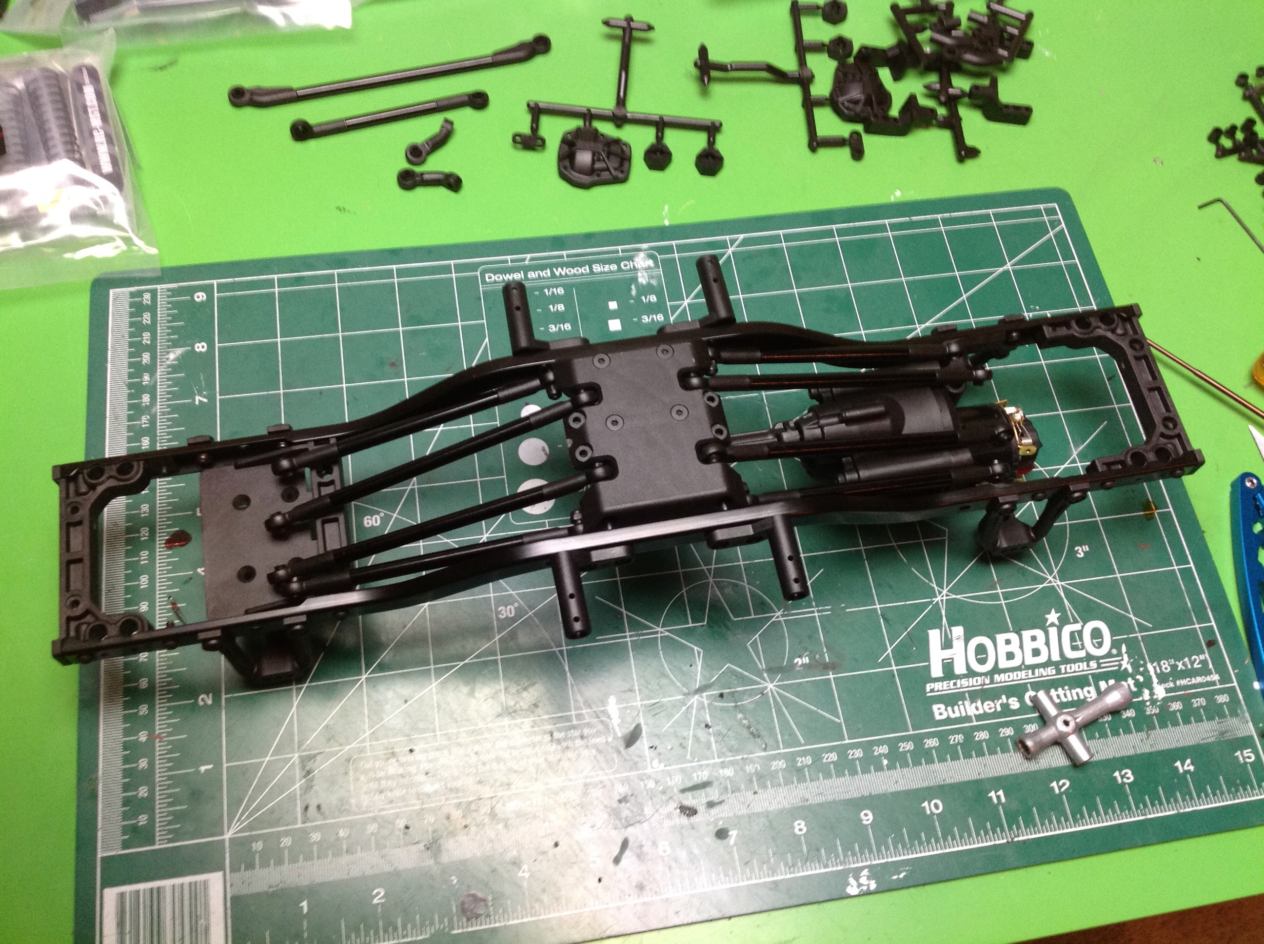
all the way to 14? I don't know. This step involves
building the ladder frame. There are front and rear plastic cross
members, a center skid, and a mid aft cross member which serves as an
electronics tray. The gearbox serves as a mid forward cross
member. With 5 cross members this thing is very stiff. The
shock hoops are also plastic and are installed at this time along with
the slider supports. The transfer case attaches to the skid and is
connected to the gearbox with a short straight drive shaft. You can see all the webbing in that skid making it extra sturdy.
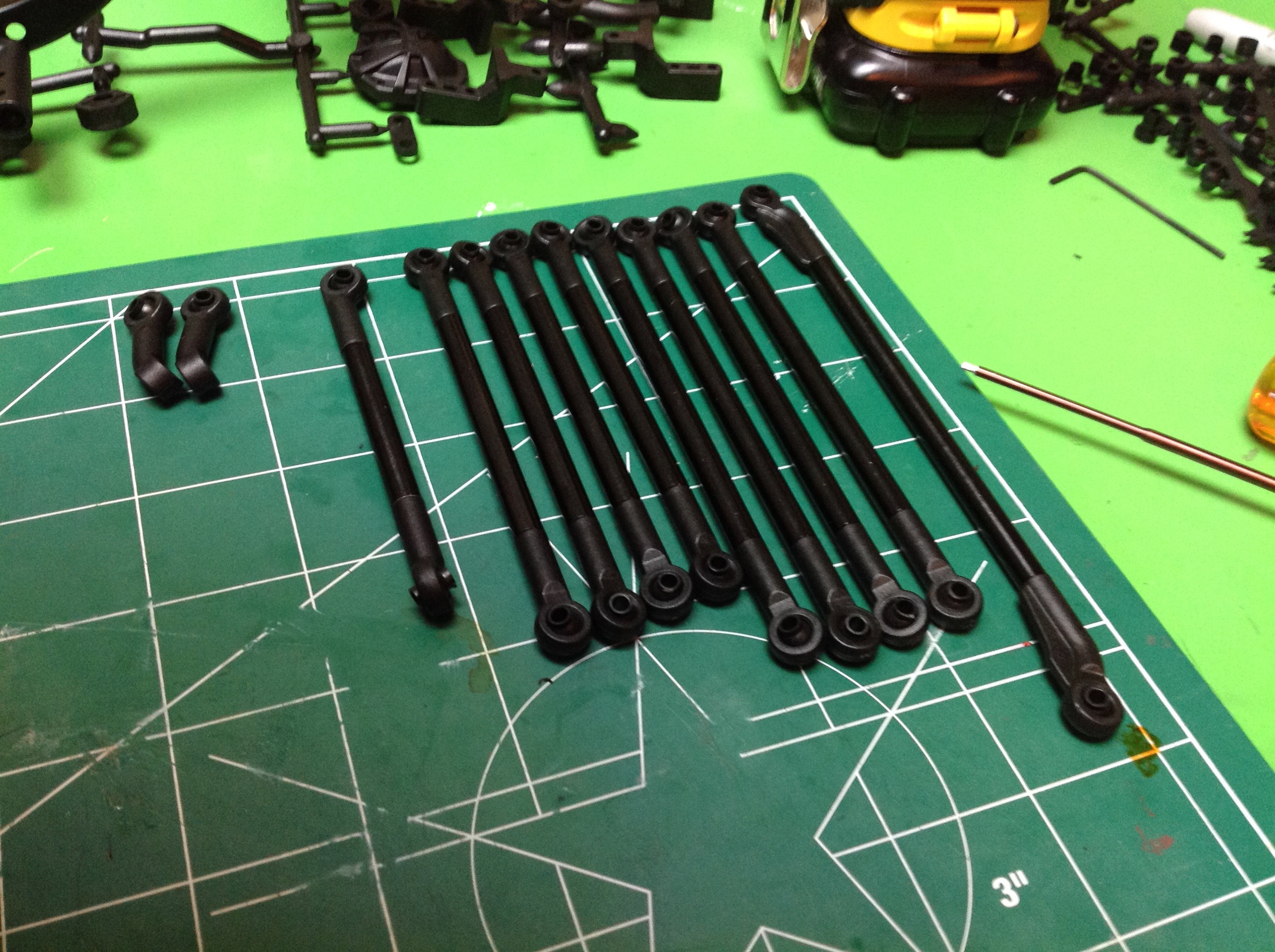
Step 4 uses parts bag 5 and builds all the links. 8 are for the
suspension, then there is a pair of steering tie rods. These are
nice metal rods using plastic rod ends. Forward and rear links are
the same length so you can't screw it up (unless you mix up upper and
lower). Those little diagonal links you see in the left hand image
are a mystery for now. We'll find out more about them later.
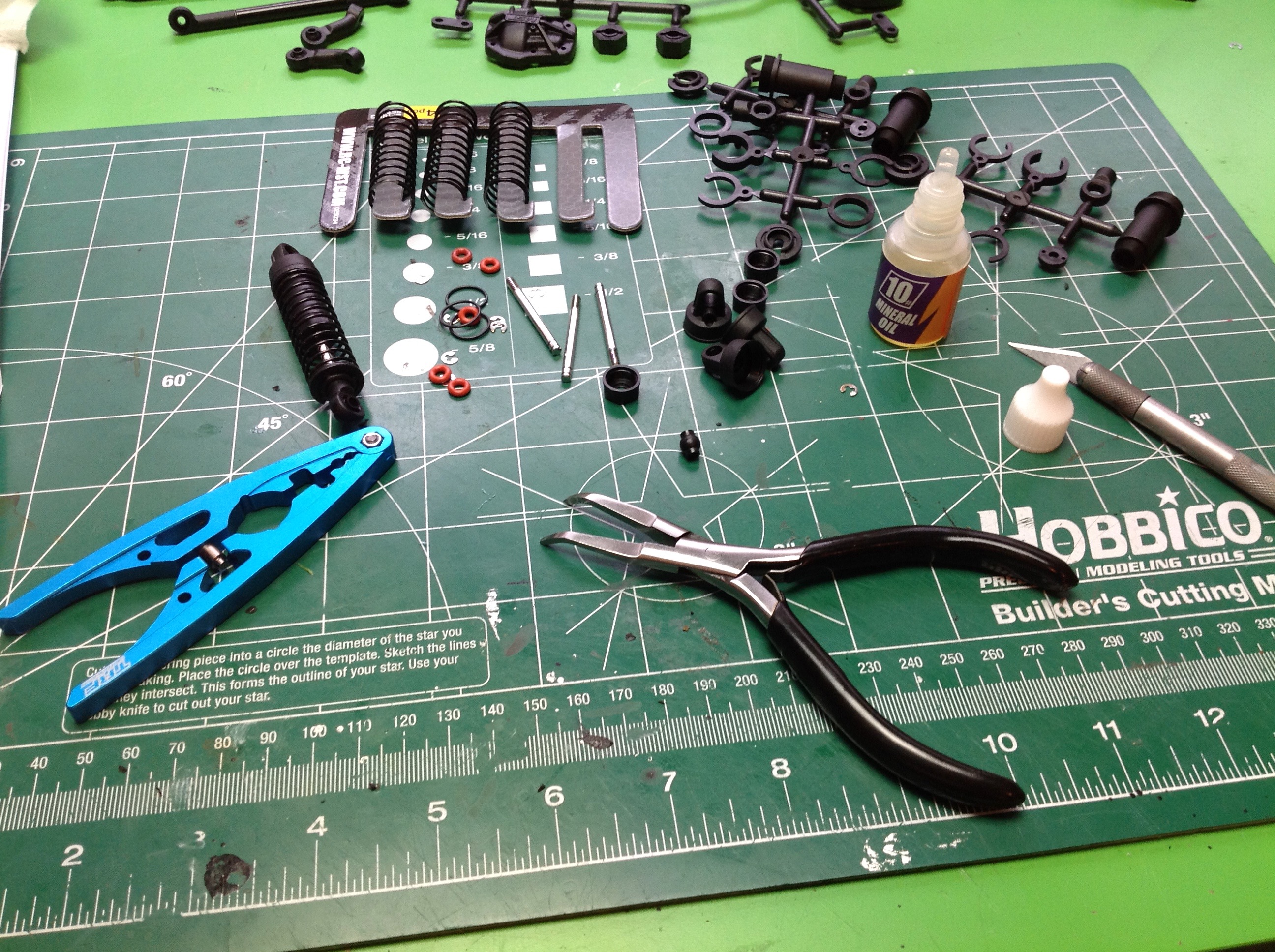
Step 5 builds, but does not install, the shocks using bag 6. These
are fully plastic oil filled shocks. Nothing special, but
adequate.
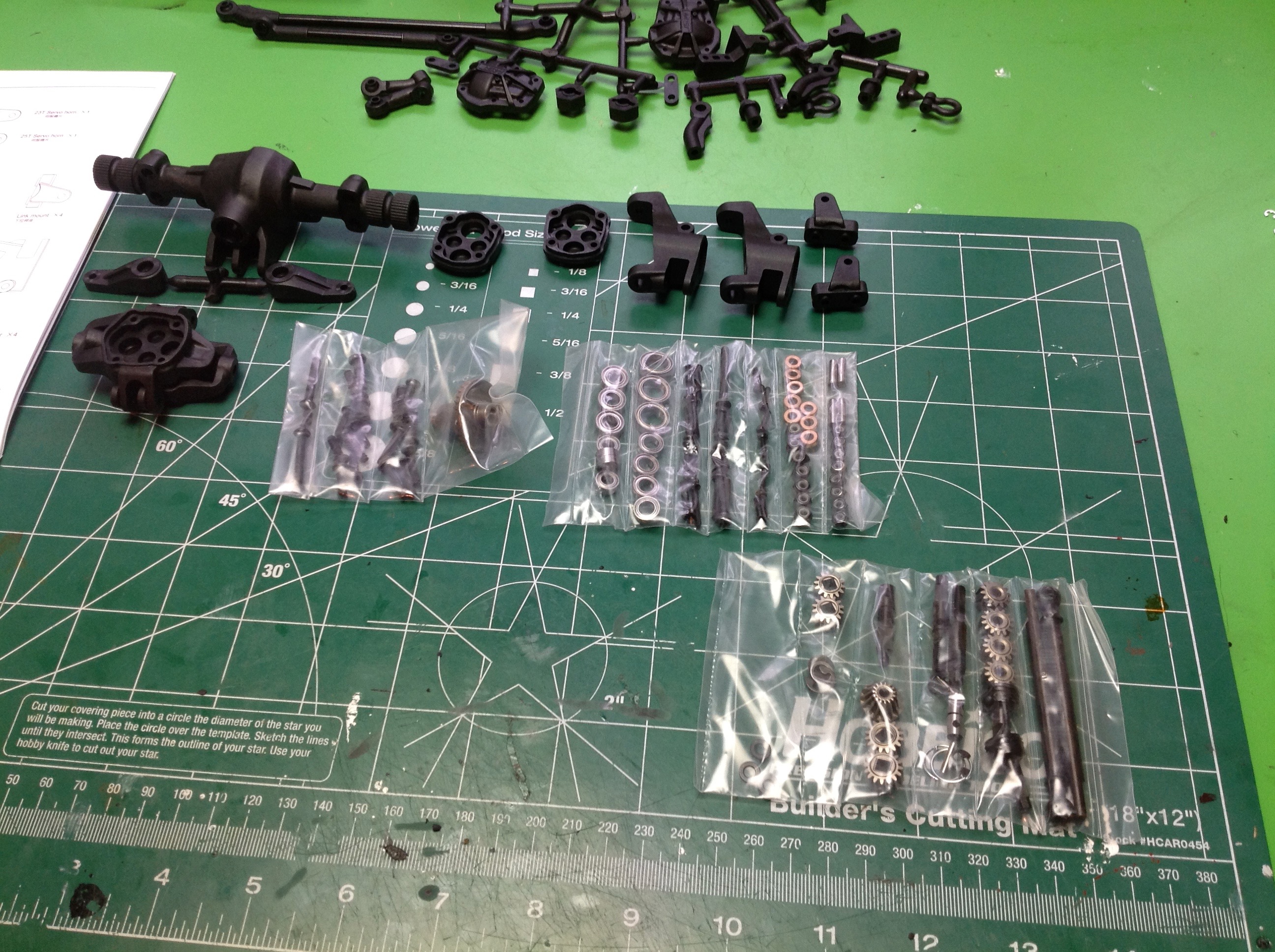
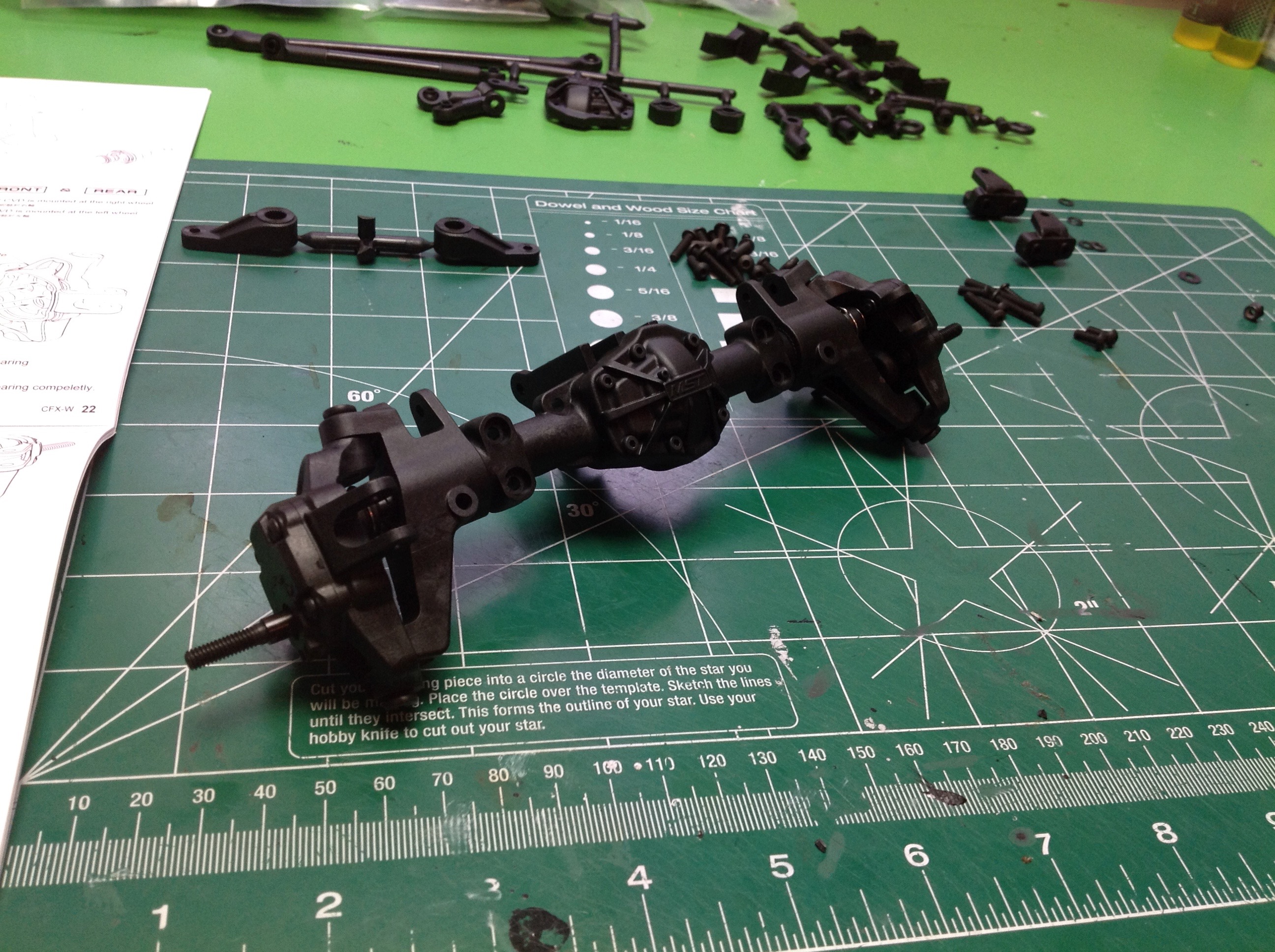
Step 6 builds the axles and requires the parts from bags 7, 8, 9, and
10. There are a LOT of parts there for just axles. Look at
all those bearings and gears! The pile of parts you see there are
just for a single axle, but the front and rear axle are exactly the same
so we get to build it twice.
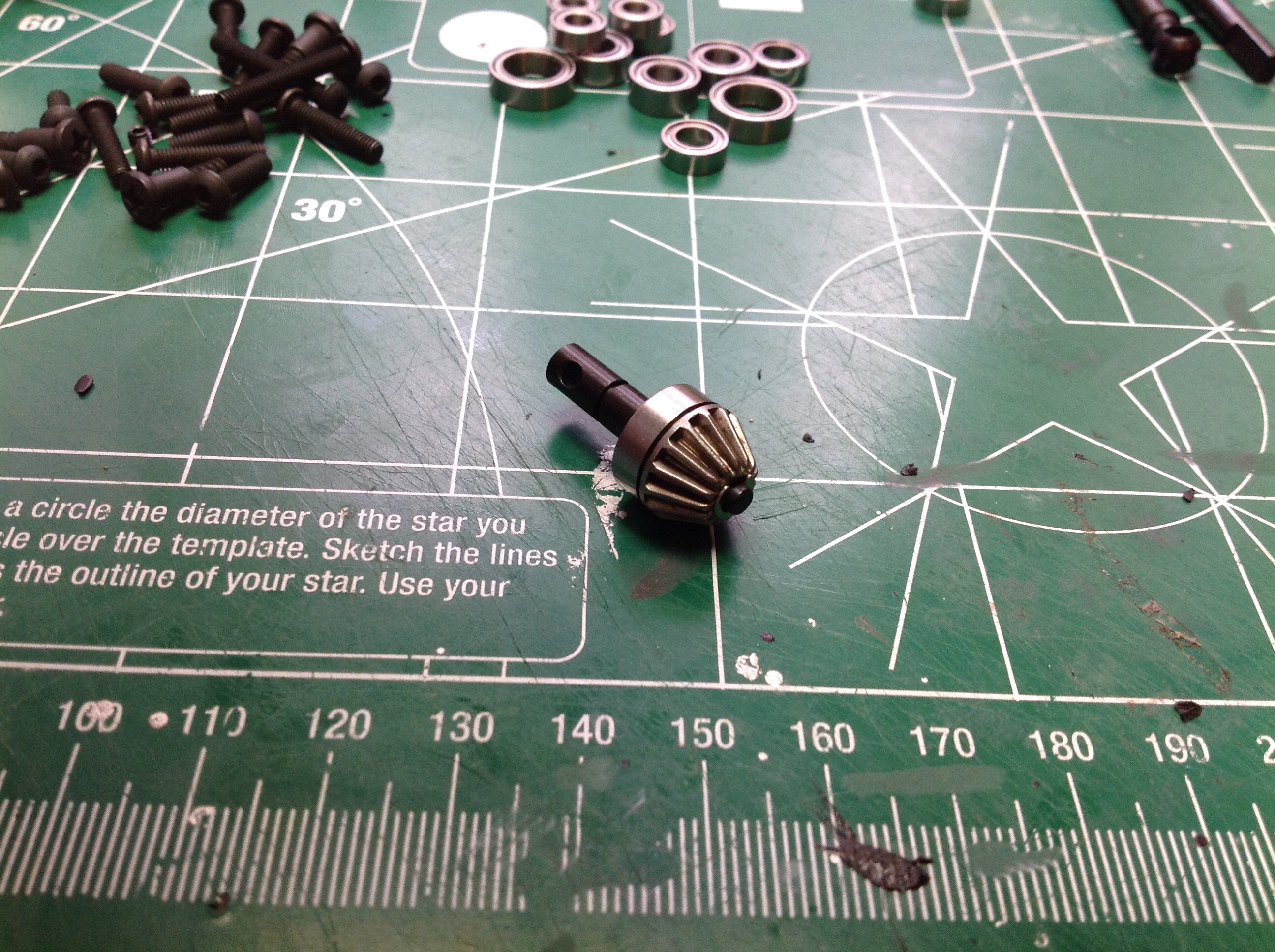
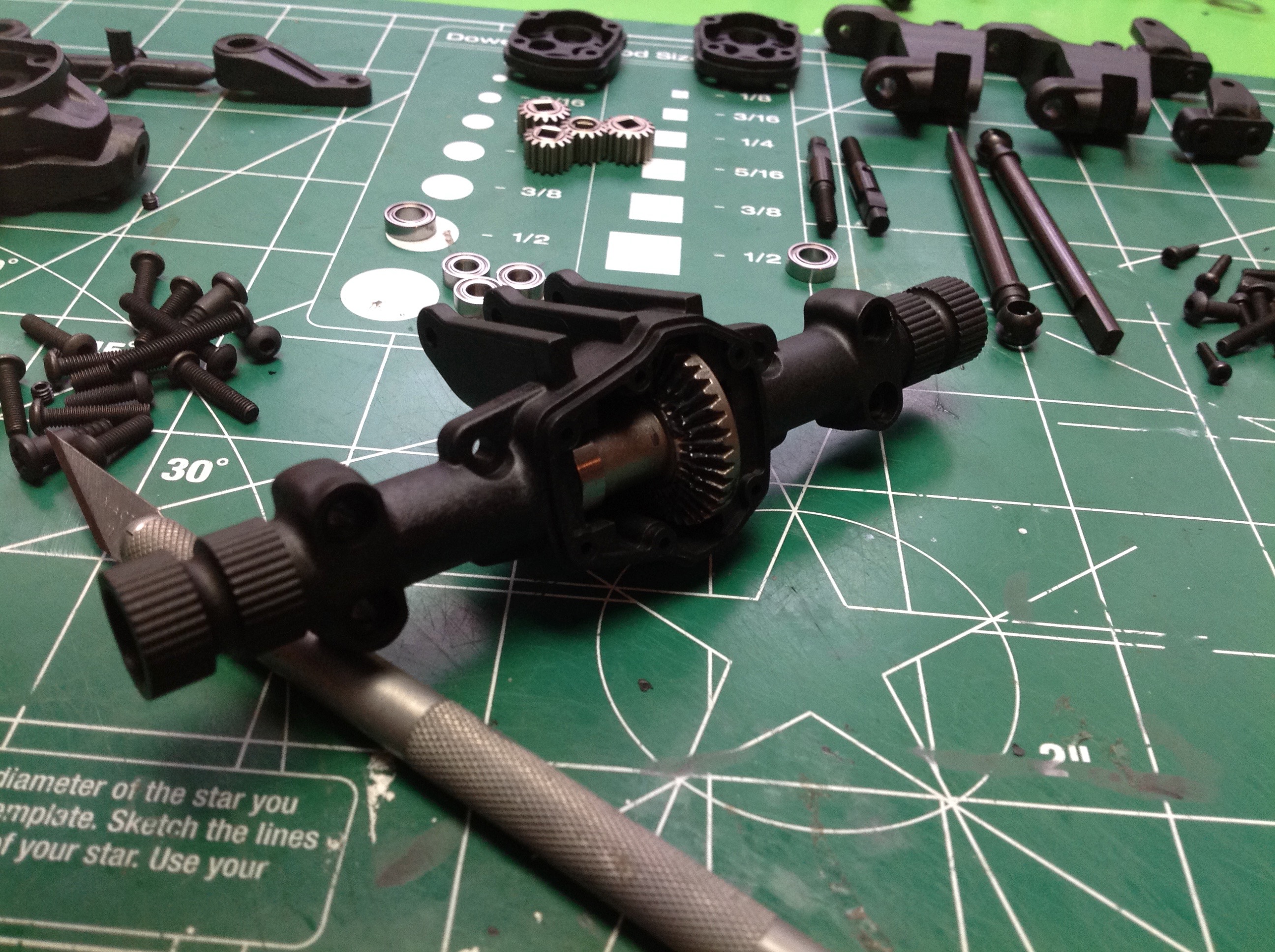
We start with the differential which isn't really a differential at all
since it is locked. The ring and pinion are straight cut bevel
gears of 36 and 15 teeth, respectively. This results in a 2.4:1 reduction.
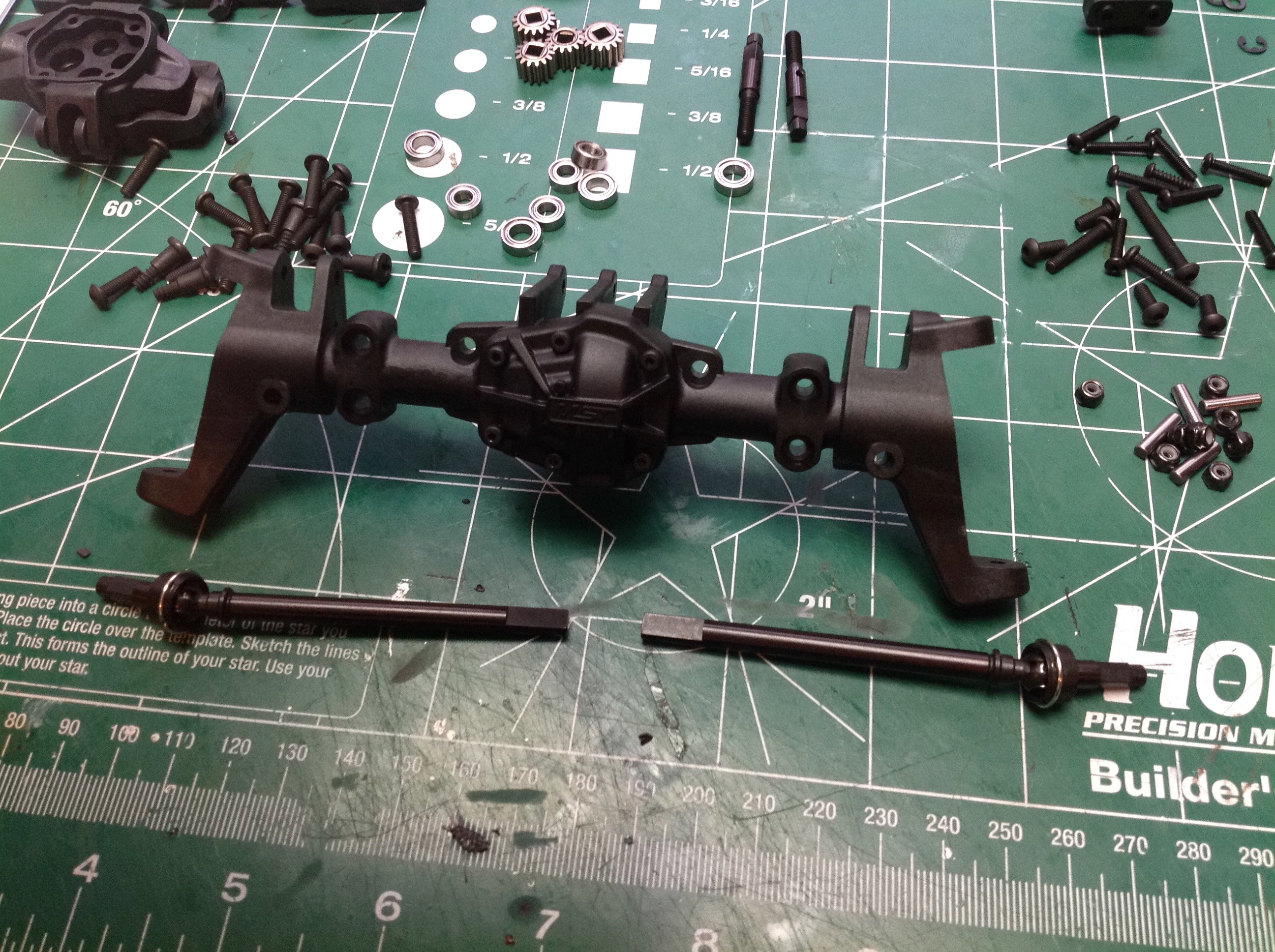
Now the nice CVD axles are built and inserted. Here's something
that shows the designers were using their heads. The
CVDs are built left and right. The difference is the direction you
install the spiral clips which retain the cross pins. You want the
axle
to rotate in the direction that tends to keep the clip in place, not
the direction that would tend to pop them off so they are build as
mirror images. Just don't back up too much! The C-hubs can
be installed with various kingpin inclinations. The stock setting
is 10 degrees, but you can reduce it to 0 or increase it to 20.
The inclination on the rear axle is meaningless since it does not steer.
A typical portal axle has only two gears: a driver and a follower.
This usually results in some significant gear reduction in the
hub. In the CFX-W there is very little reduction: just 16:14 =
1.14:1. It includes a set of idler gears to generate an even
larger offset between the wheel axle and the drive axle.
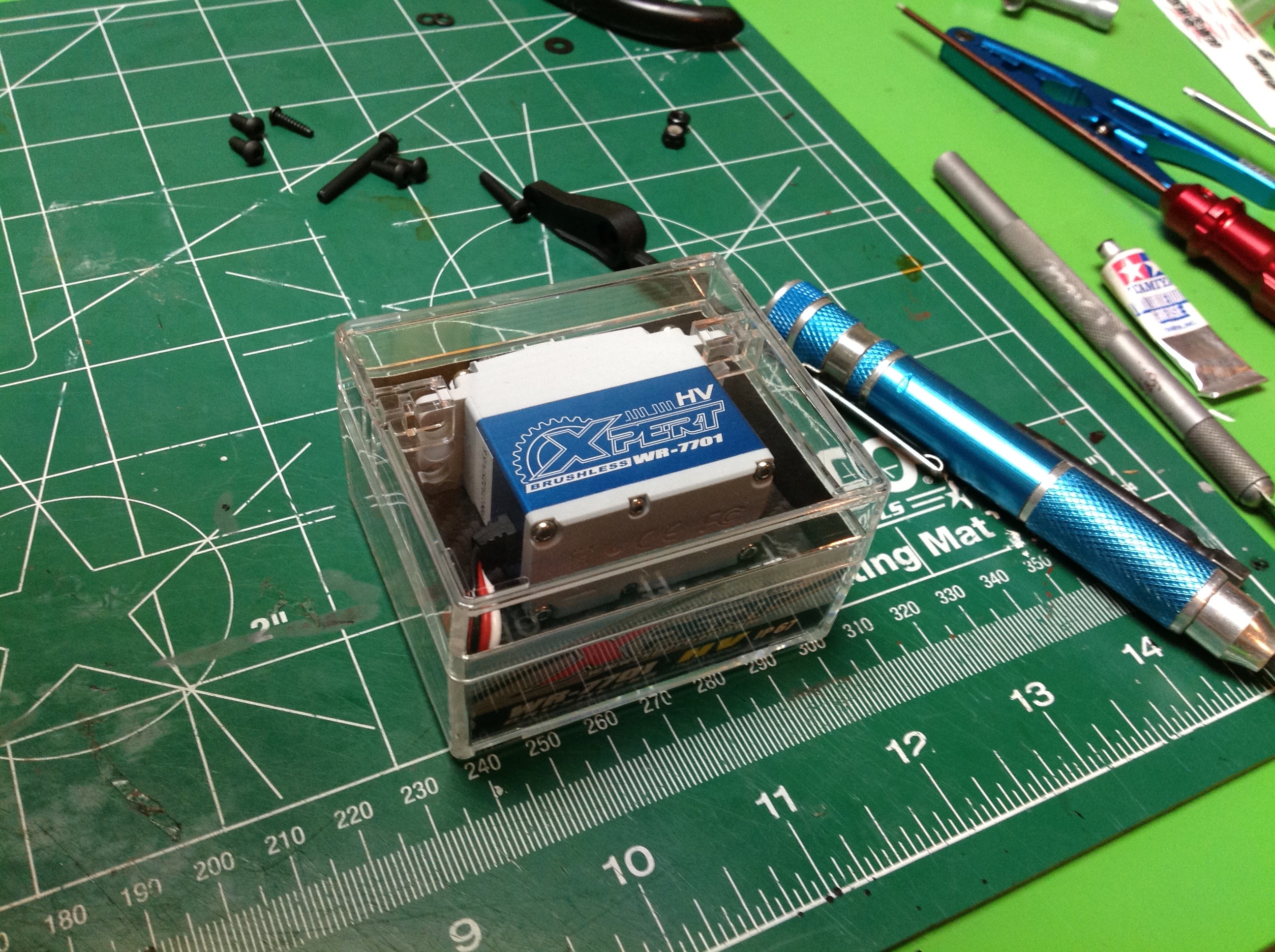
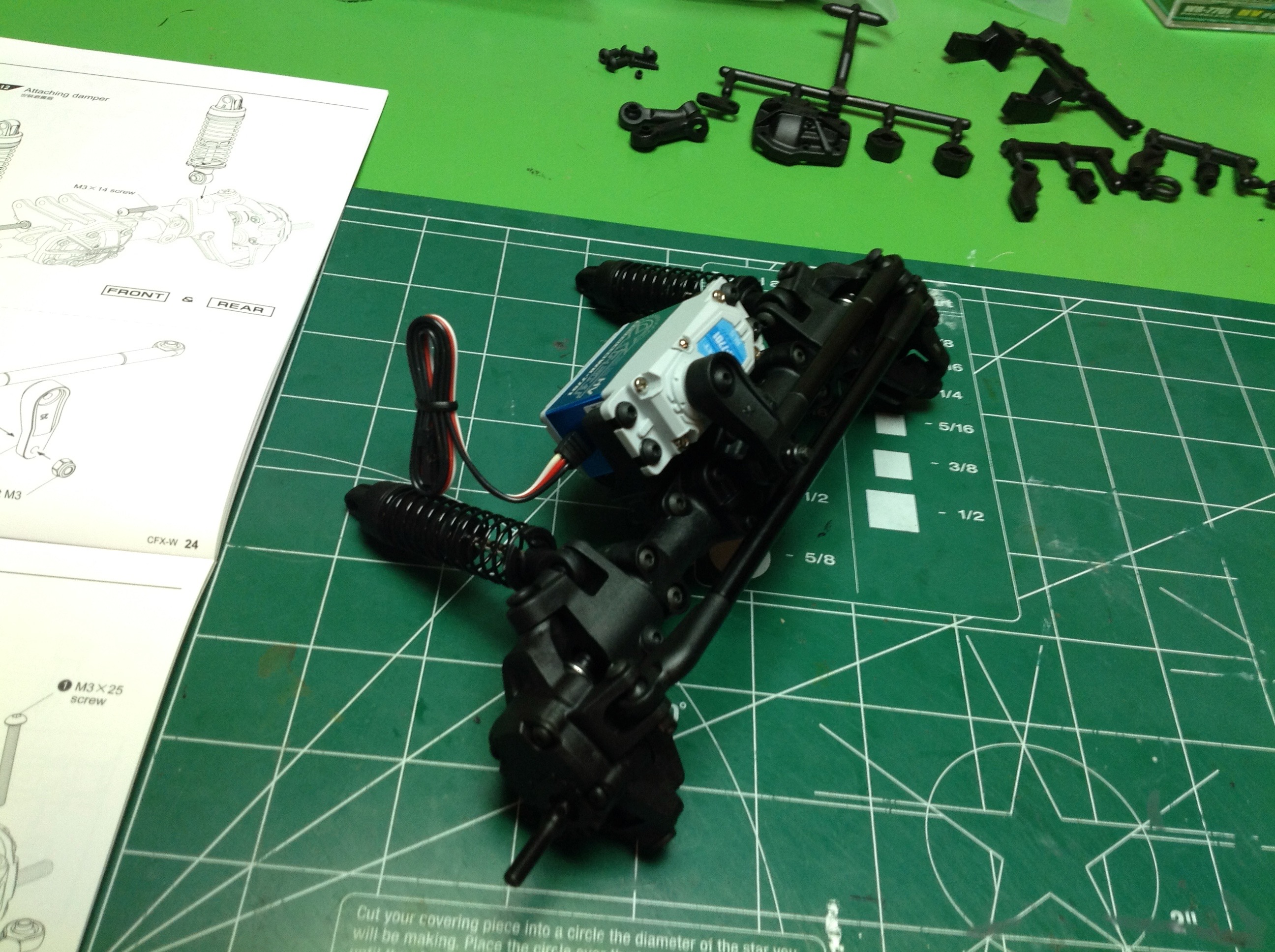
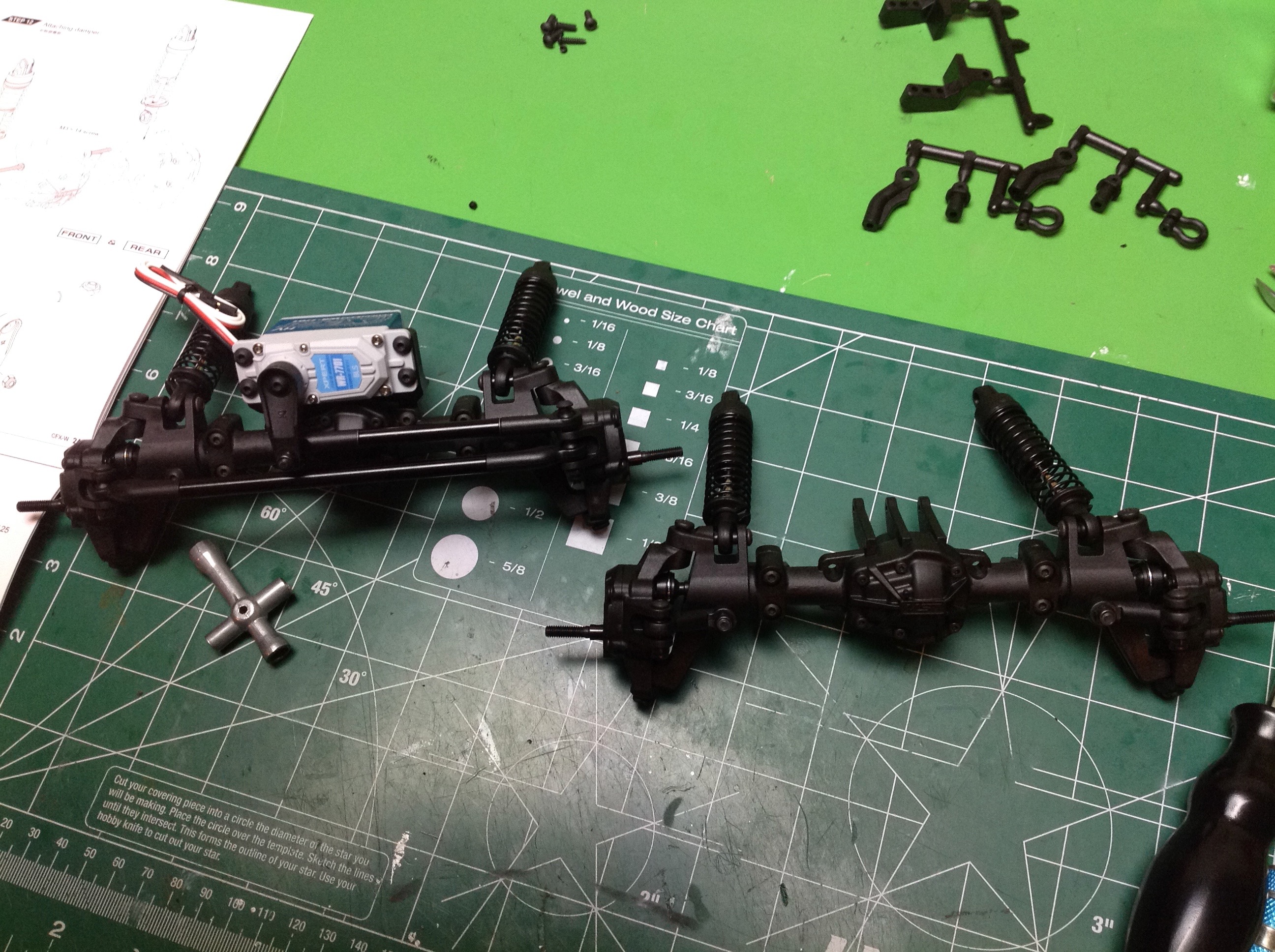
Time to install the steering servo which is mounted to the axle. I
decided to try out an Xpert servo. I'd never heard of them, but
the specs were impressive and the price was right. This is a high
torque, waterproof, metal gear servo. So far it has performed very
well indeed and I've used it on more than one vehicle since. The
right hand image shows the servo installed along with the tie rods and
shocks.
Here are the completed front and rear axles. Those little diagonal
braces from earlier are used to lock the steering angle on the rear
axle. If you wanted to, nothing is stopping you from making this
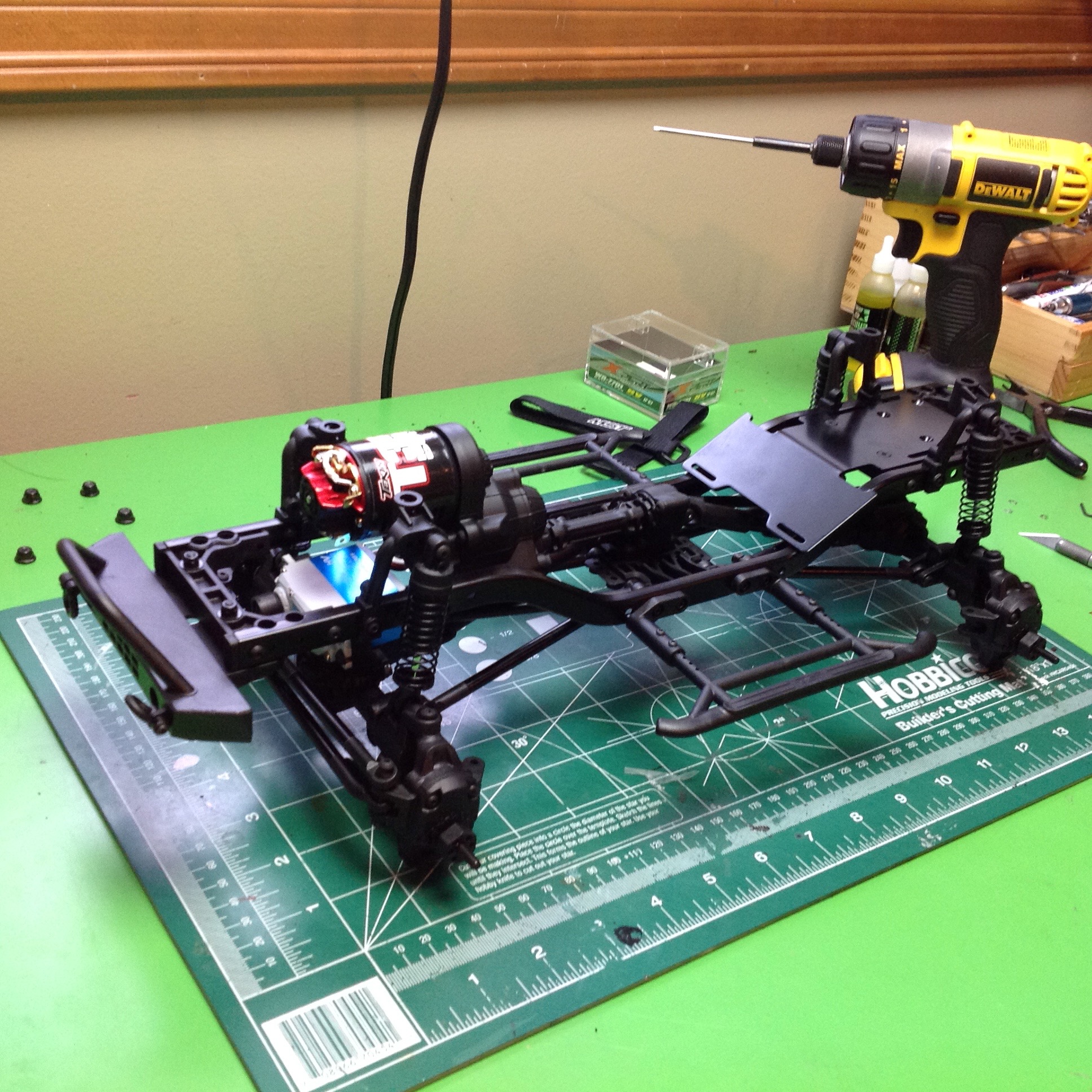
4-wheel steering. Step 7 uses parts bag 11 to build the drive
shafts which are splined plastic telescoping units with universal
joints. Now the axles can be attached to the links, the shocks to
the shock hoops, and we have a chassis! I've also installed the
bumpers from Step 8, although I will be removing them later when I put
on the body. You can also see the battery tray behind the transfer
case.
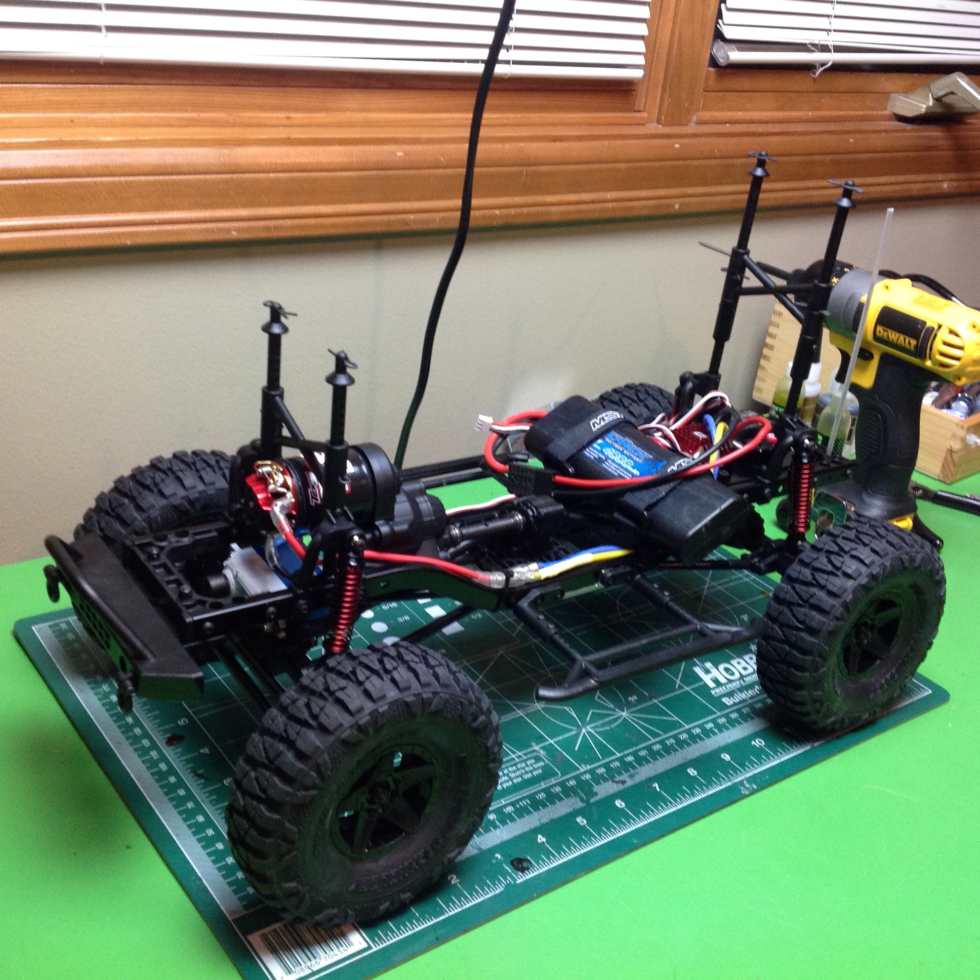
Step 9 builds the wheels and tires. These are plastic wheels which
are not beadlocks. I knew I was going to change them so I didn't
bother gluing them. The tires are actually really nice. This
final image shows the installation of the electronics and factory body
mounts. I used a Hobbywing crawler controller which I
really like. There are also some upgrades visible here which I'll
talk about on the next page.
©2018 Eric Albrecht