Tamiya Clod Buster Project
Page 1: Stock Assembly
I did a terrible job of documenting the build of
this iconic truck. Luckily, I later returned to build the Black
Edition of the same truck and did a much better job the second time
around. The chassis are identical apart from the color, so take a
look at that page for a lot more build detail.
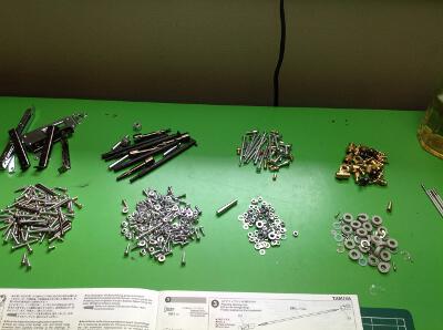

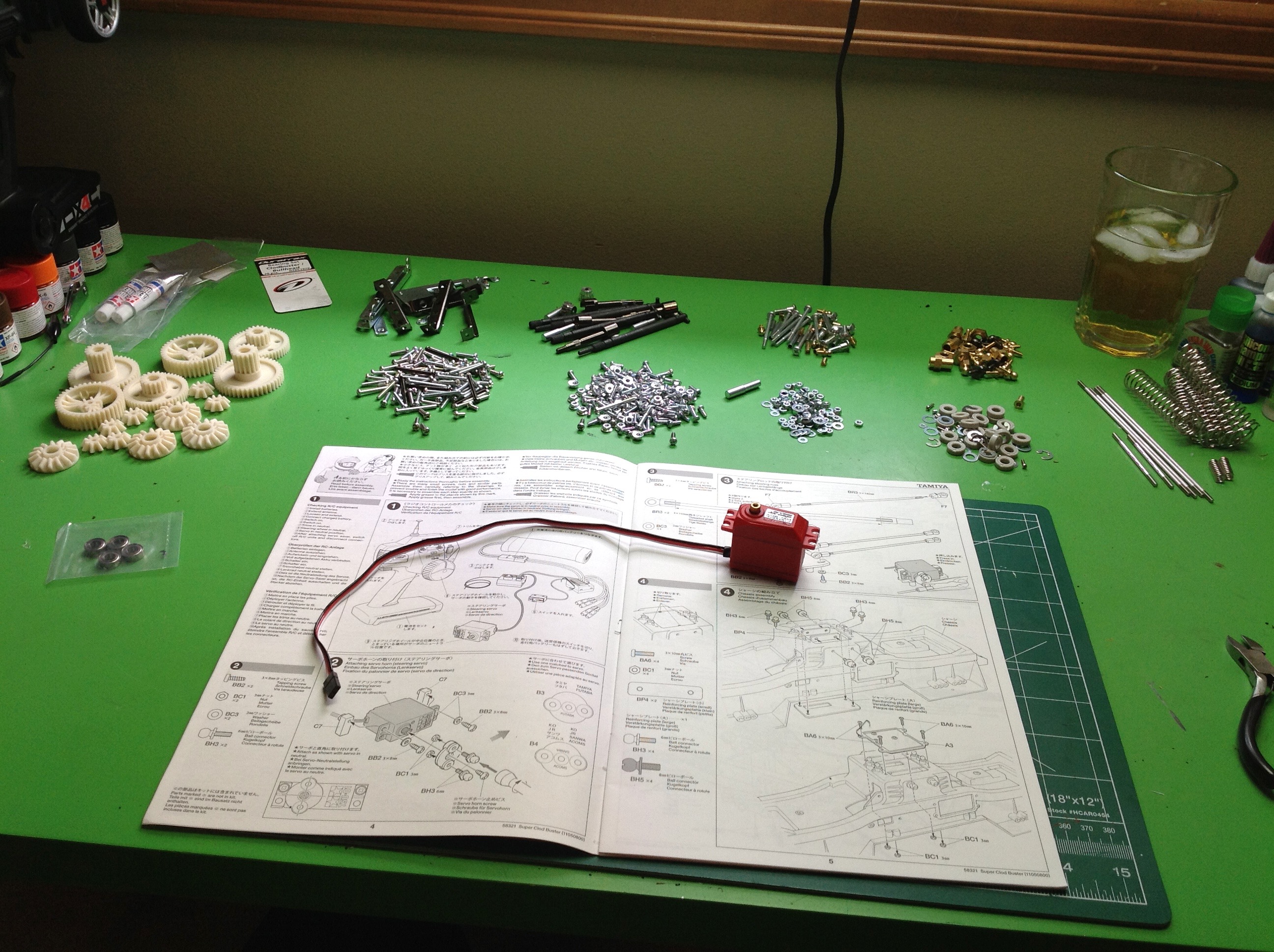
The Clod Buster has a LOT of hardware and it is really heavy. The
first photo shows an assortment of some of it. There are actually a
fairly small number of types of screws making it easy to find what you
are looking for. The build starts off immediately with the
electronics and the steering servo comes first. Although this
model has 4 wheel steering, it only uses a single chassis mounted
servo. For this reason you need to use one with plenty of
torque. This is an ARRMA 15 kg (208 oz-in) waterproof servo with
metal gears. Even with all the torque, the steering isn't very
good because most of the torque is lost in the servo savers on the
axles.
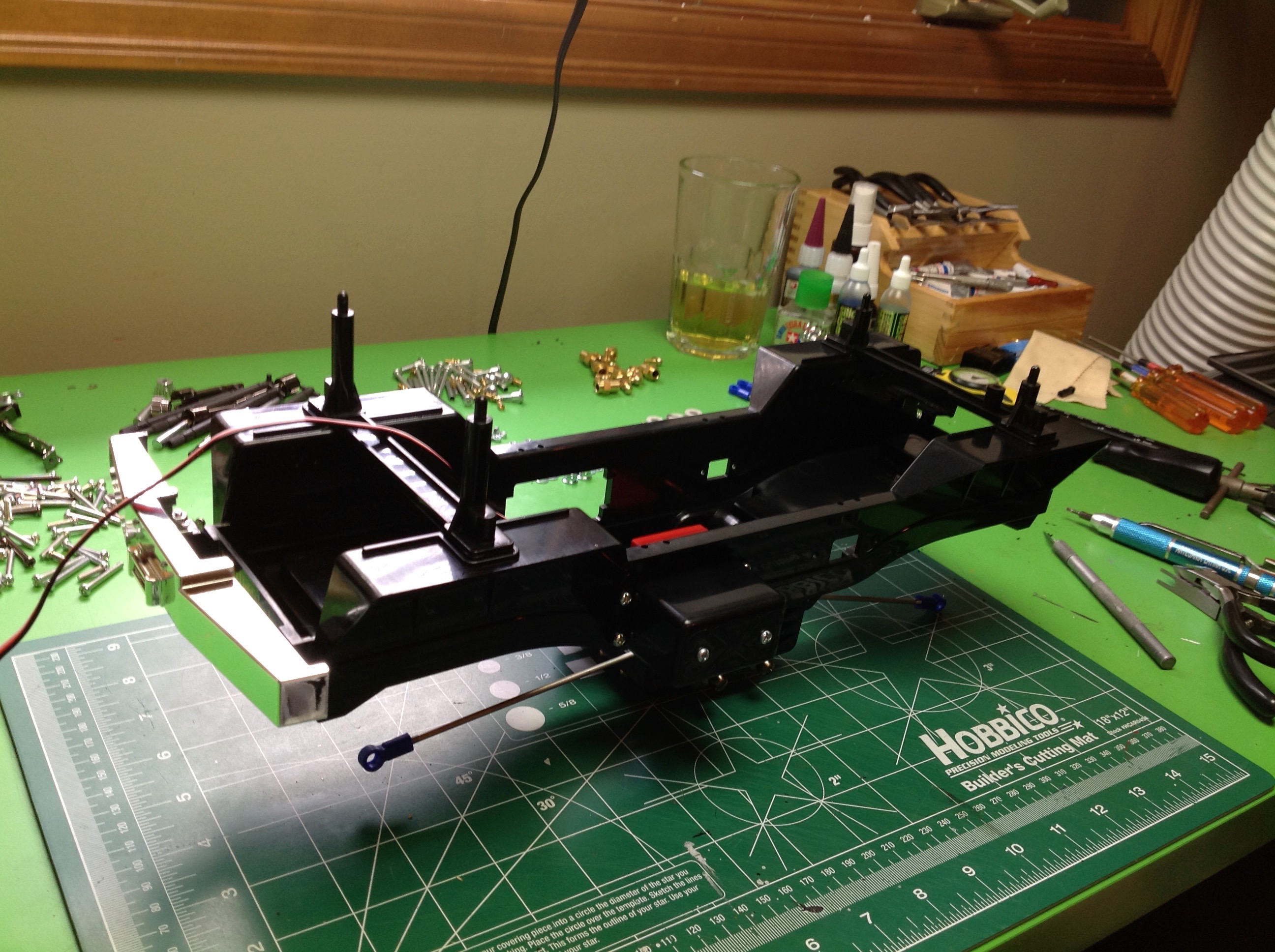
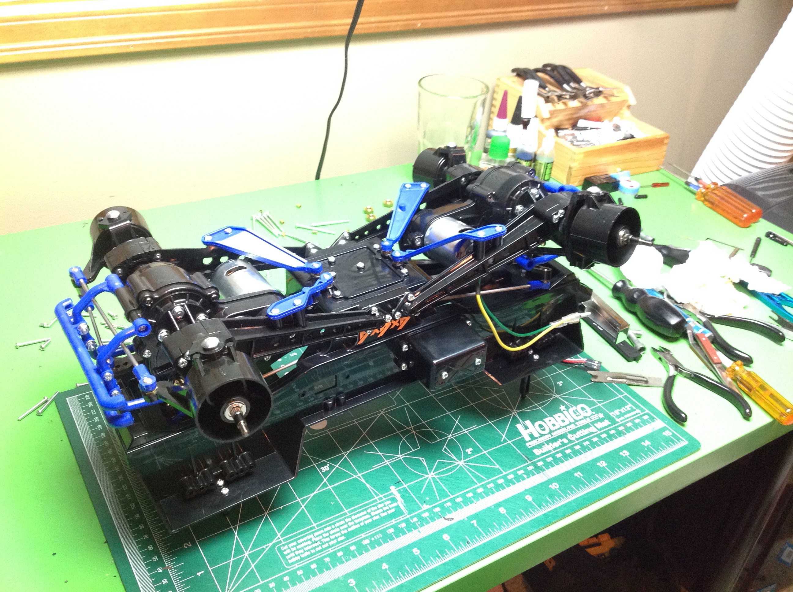
The main chassis tub is all one piece but it is reinforced and stiffened
with a few metal inserts where the suspension links attach. The
steering rods run along the length of the body in either direction.
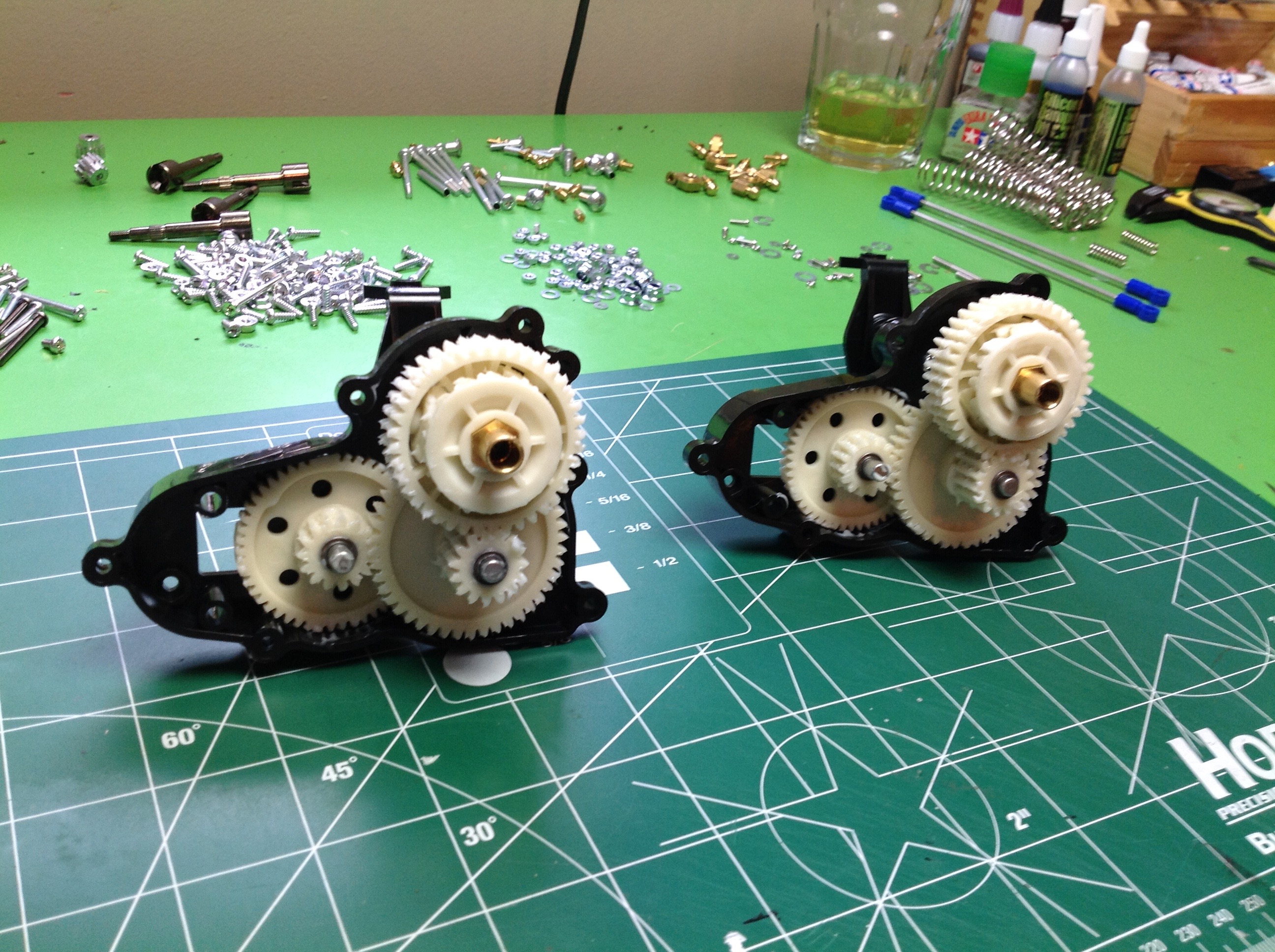
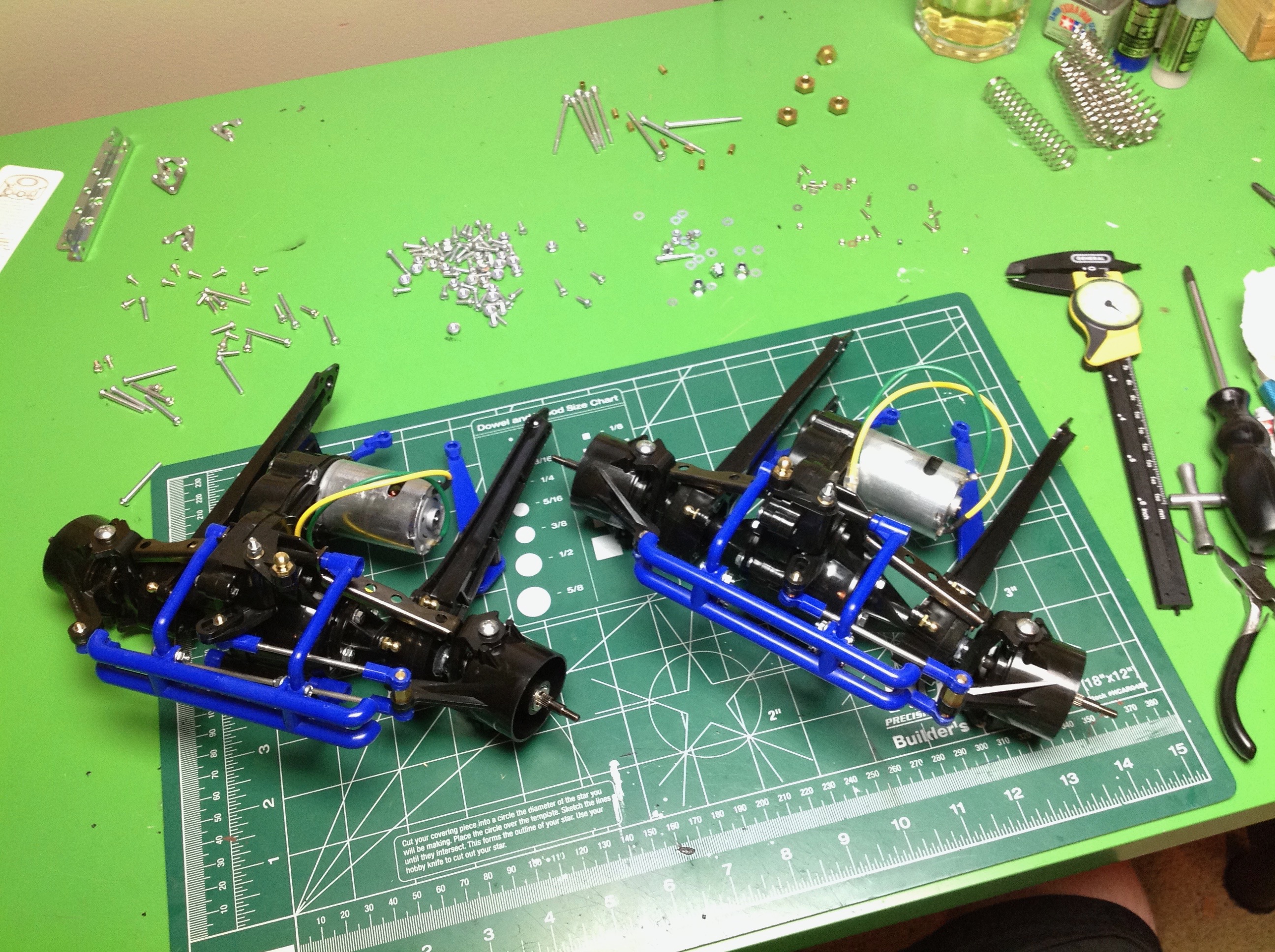
There is no central gearbox or transfer case in the Clod. Since
the motors are mounted on the axles, the gearboxes must also be on the
axles. You build two identical powered axles, and each contains an
integral gear differential. The gears are HUGE! You will
not be stripping any of these gears any time soon. The
differentials cannot be locked, but you can make them tighter with some
anti-wear grease.
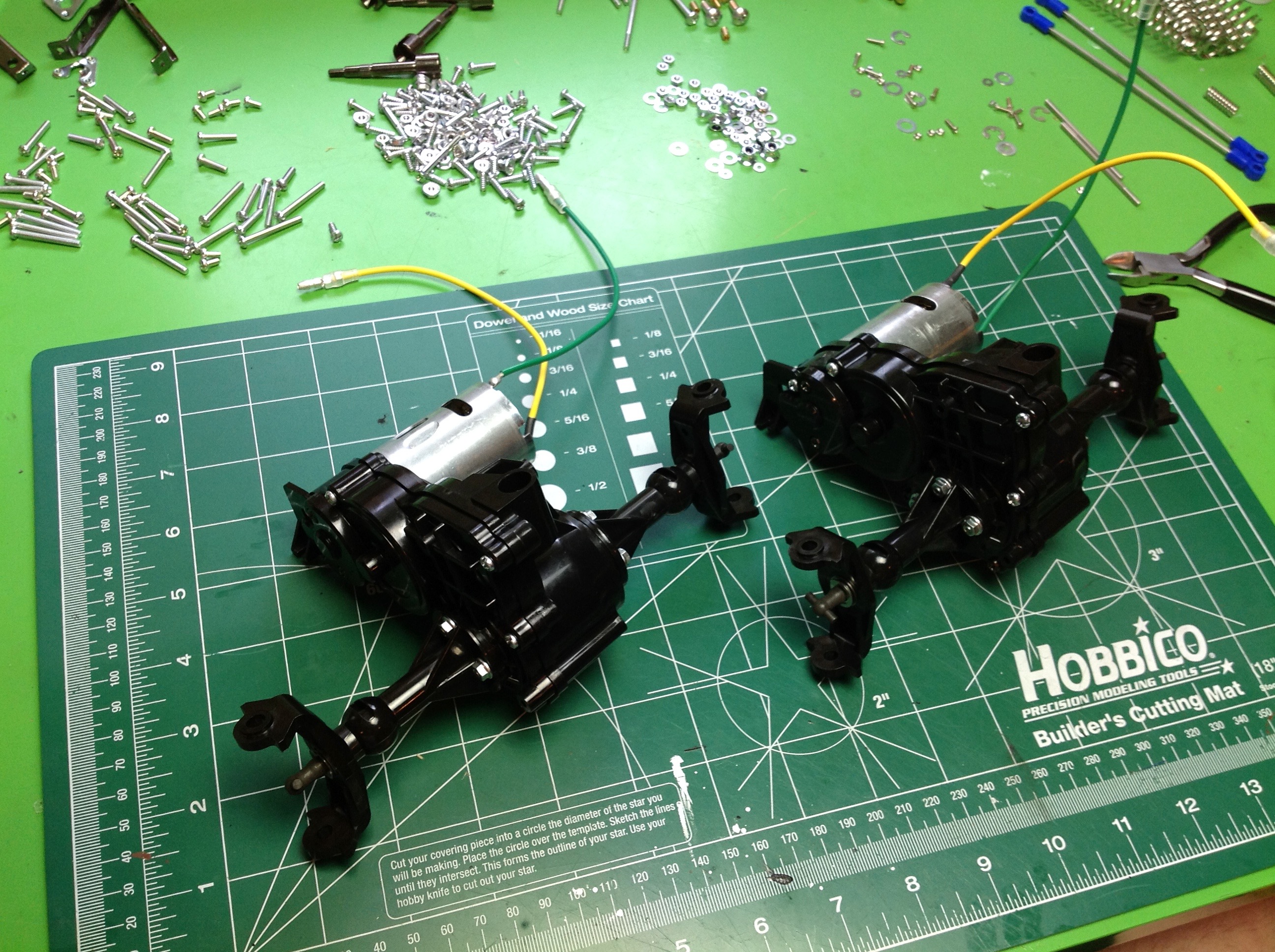
The front and rear axles are no longer quite the same. They both
use the same bumper and suspension links, but the servo savers are
assembled a little differently. Because both steering rods are on
the same side of the chassis but one of the axles is installed
backwards, you need to build the servo saver with the crank facing the
other way. I also adjusted the position of the ball stud so that
the rear steering would have less travel than the front. The
suspension links are a bit unusual because they are not just rods but
actual profiles. The blue lower links are a soft flexible plastic
and must actually bend because they mount in 3 places. The black
links connect to a ball joint on the side of the chassis. All of
the rod ends are a really tight fit on the balls so it is not easy to
remove them to make adjustments. Try to get it right the first
time. I did not follow this advice.
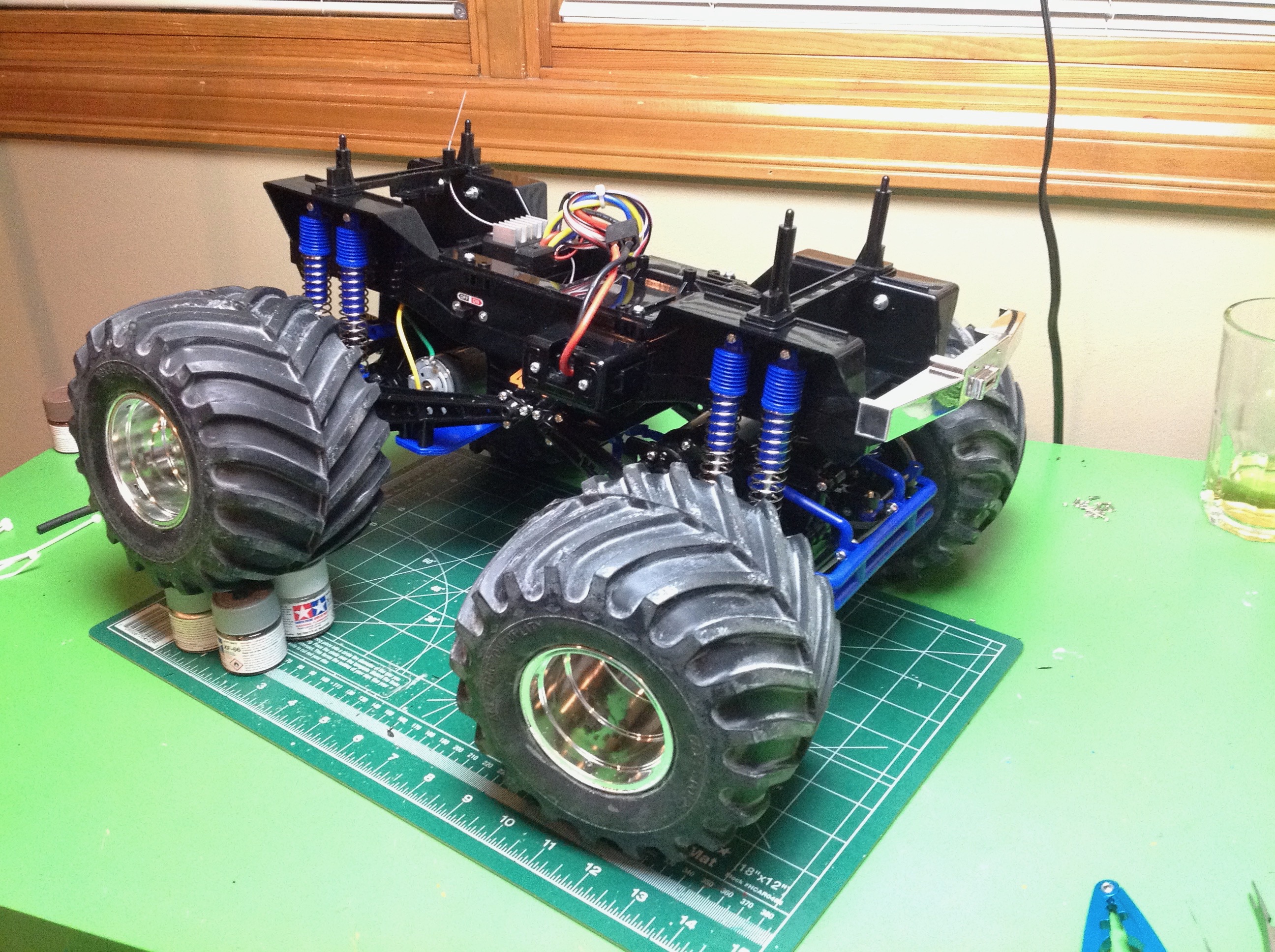
The completed chassis. The shocks are "friction damper" type which
means they have no oil. In fact, they have no damping
either. These are as simple as shocks can get, just rods in a
can. In practice, the tires are so bouncy that the shocks probably
don't do much. Despite the long length of the shocks, they also
have very little travel. This is just as well because the servo
saver bottoms out on the chassis tub quite easily. The battery is
mounted in a slot accessed from the side of the chassis. I really
like this because it means you don't have to remove the body to change
the battery.
I used a Tamiya TEU-106BK speed controller which can control two
parallel bushed motors. You only need a two channel radio since
the four wheel steering uses one servo.
©2017 Eric Albrecht