Tamiya Clod Buster Project
Page 2: Upgrades!
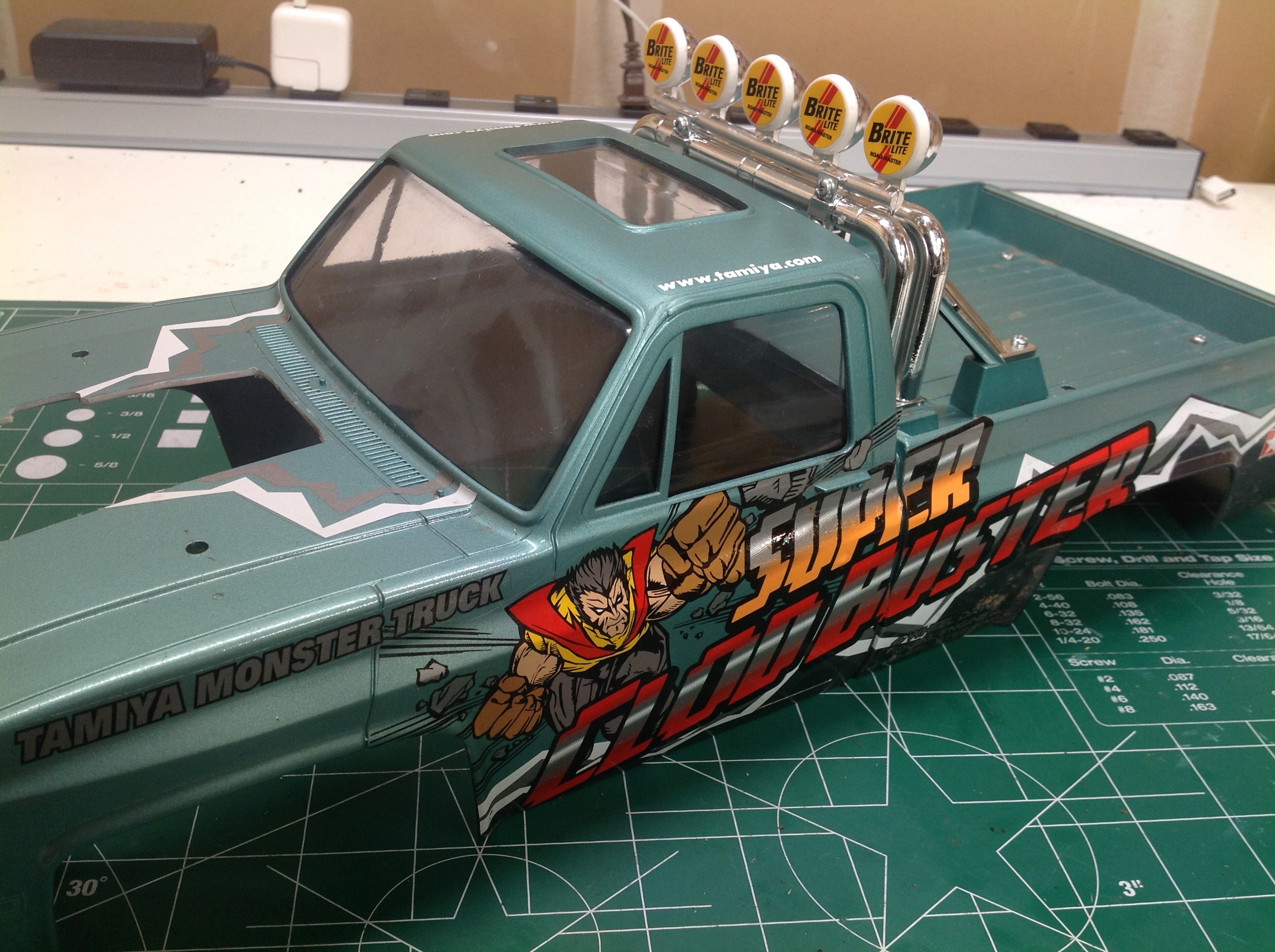
Let's get something out of the way right from the start. The
Clod Buster is not a high performance truck. Adding high
performance parts to it pretty much just makes it worse. This is
an old design truck made for bouncing around the lawn, and it does that
job just fine. The upgrades I made were mostly just for fun, and
in most cases I had to make additional mods just to restore the original
performance.
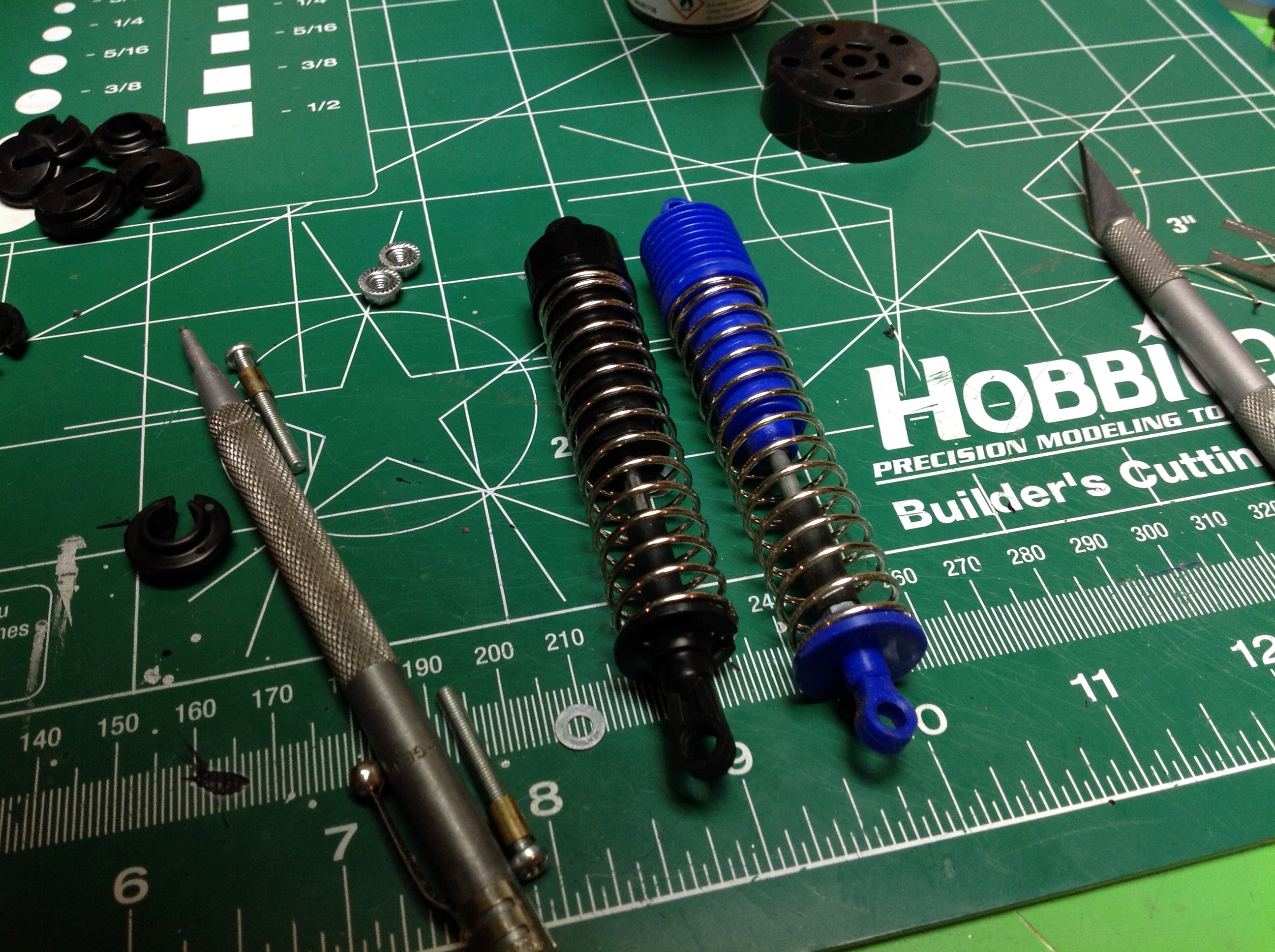
The friction dampers are adequate for this truck, but it still bothers
me to have "shocks" which are so low-tech. I happened to have 8
extra oil shocks from my TXT-2 because I upgraded that truck to aluminum
shocks. They are not quite the same length, but if you put the
longer rod ends on the oil shocks they are pretty close. I can't
claim to have actually noticed any performance difference after
installing these shocks, but they do make me feel better somehow.
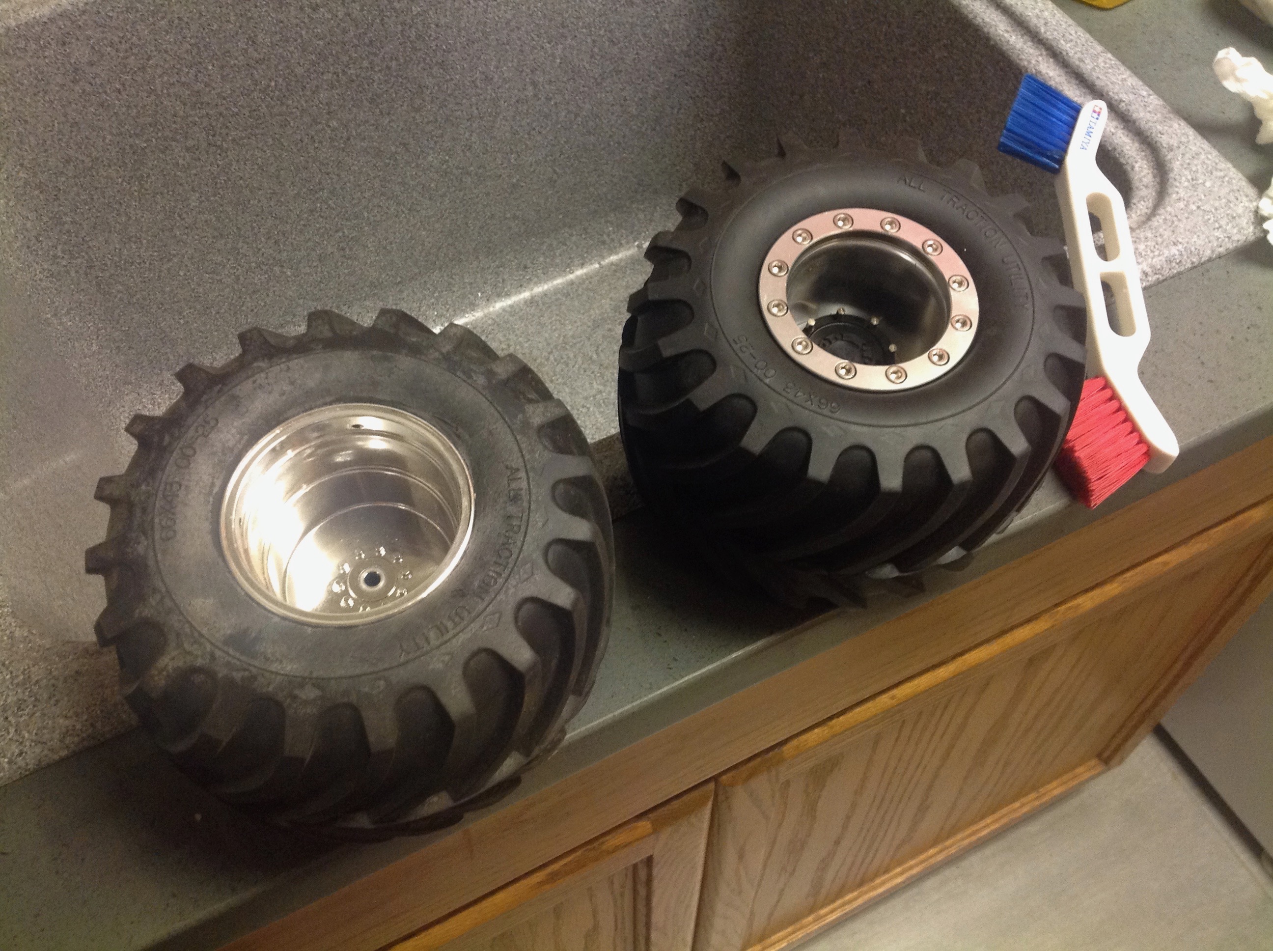
RC4WD offers aluminum beadlock wheels for the Clod Buster, and I thought
they were so cool that I ordered them before even building the
model. You also need an adapter to fit the hex size of your
particular model, in this case that's 12mm. In the pictures you
can see the stock plastic wheel compared to the aluminum wheel, front
and back. In the first photo you can also see the white mold
release agent that was present on the tires out of the box. It
took me a lot of scrubbing with my official Tamiya brush to get them to
look smooth and clean on the right.
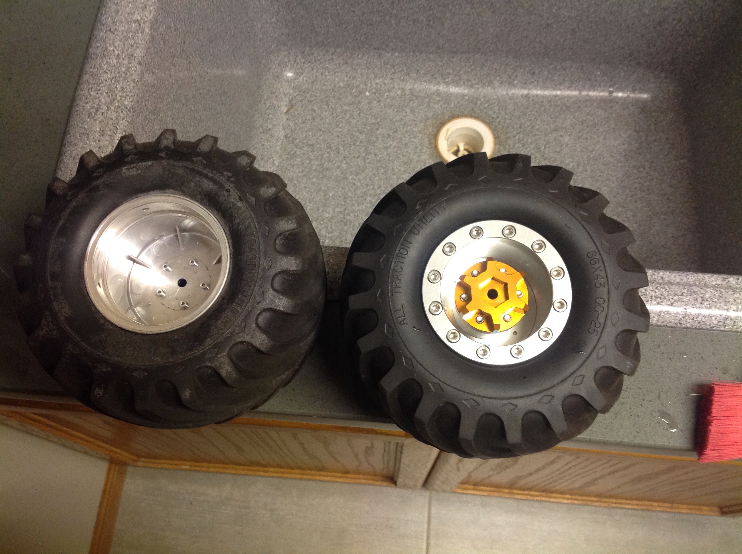
As cool as these new wheels are, they are a big problem. First of
all,
the Clod Buster steering system is terrible right out of the box.
All of the servo force is lost in the servo saver, and the steering
geometry is all wrong. The Ackerman angle is backwards and so is
the caster. The result is that the front wheels basically don't
steer at all and the back wheels steer a lot so it drives like a
forklift. The aluminum wheels
do not have the same offset as the stock wheels which results in the
track width increasing by almost two inches. While this might be
good for stability, it makes the steering completely unusable and it
doesn't look right either. To solve the problem, I decided to
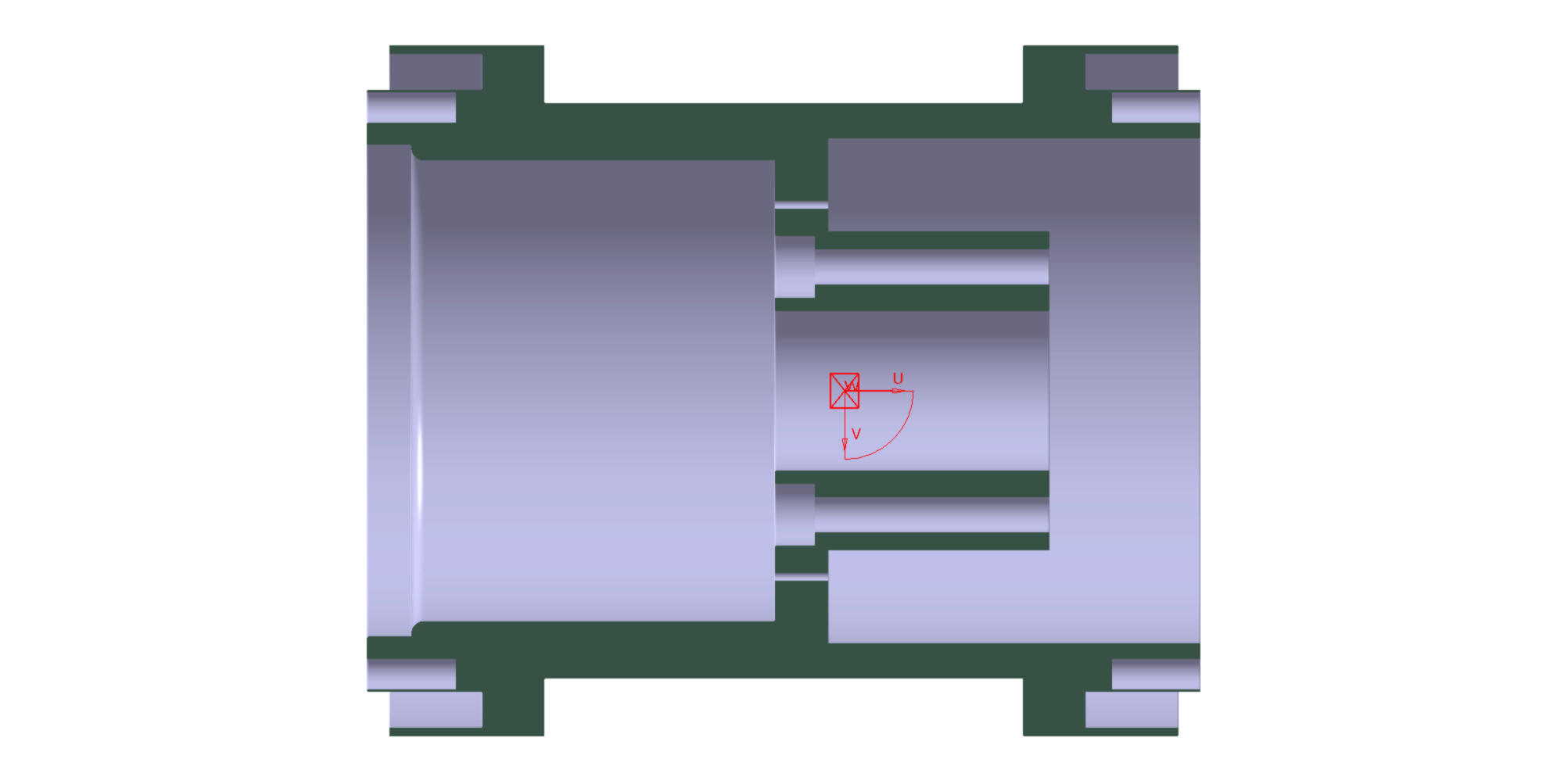
modify the wheels to decrease the offset. The pictures above show
the CAD model I made of the wheels. On the left is the aluminum
wheel as it comes from RC4WD. Once the adapter is on, the mounting
face is essentially flush with the edge of the wheel. I wanted to
the mount to be deep inside the wheel, so I decided to remove 23mm of
aluminum which I accomplished on a friend's mill. This is a pretty
major modification and I screwed up some of the dimensions despite all
my preparations which required that I build a spacer to install the
final wheels, but in the end it worked. The difference is
incredible. It drives so much better now. Note that I also
replaced the servo horn with a much longer version to give the steering
rods more travel and tightened the servo savers almost to the
stops. There are aftermarket companies which offer conversions to
move the steering servo to the axles, but I didn't want to do this since
it ruins the scale appearance.
For reference, I did try swapping the wheels and tires with the
TXT-2. This worked OK for the Clod Buster, but the TXT-2 couldn't
handle the heavy aluminum wheels either so I switched back.
Phase 2:
Those aluminum wheels and oil shocks were nice, but I was always unhappy
with the performance of the Clod. Part of it was all the extra
weight I added, but in particular the steering was just terrible. I
resisted any kind of servo-on-axle steering because I wanted it to stay
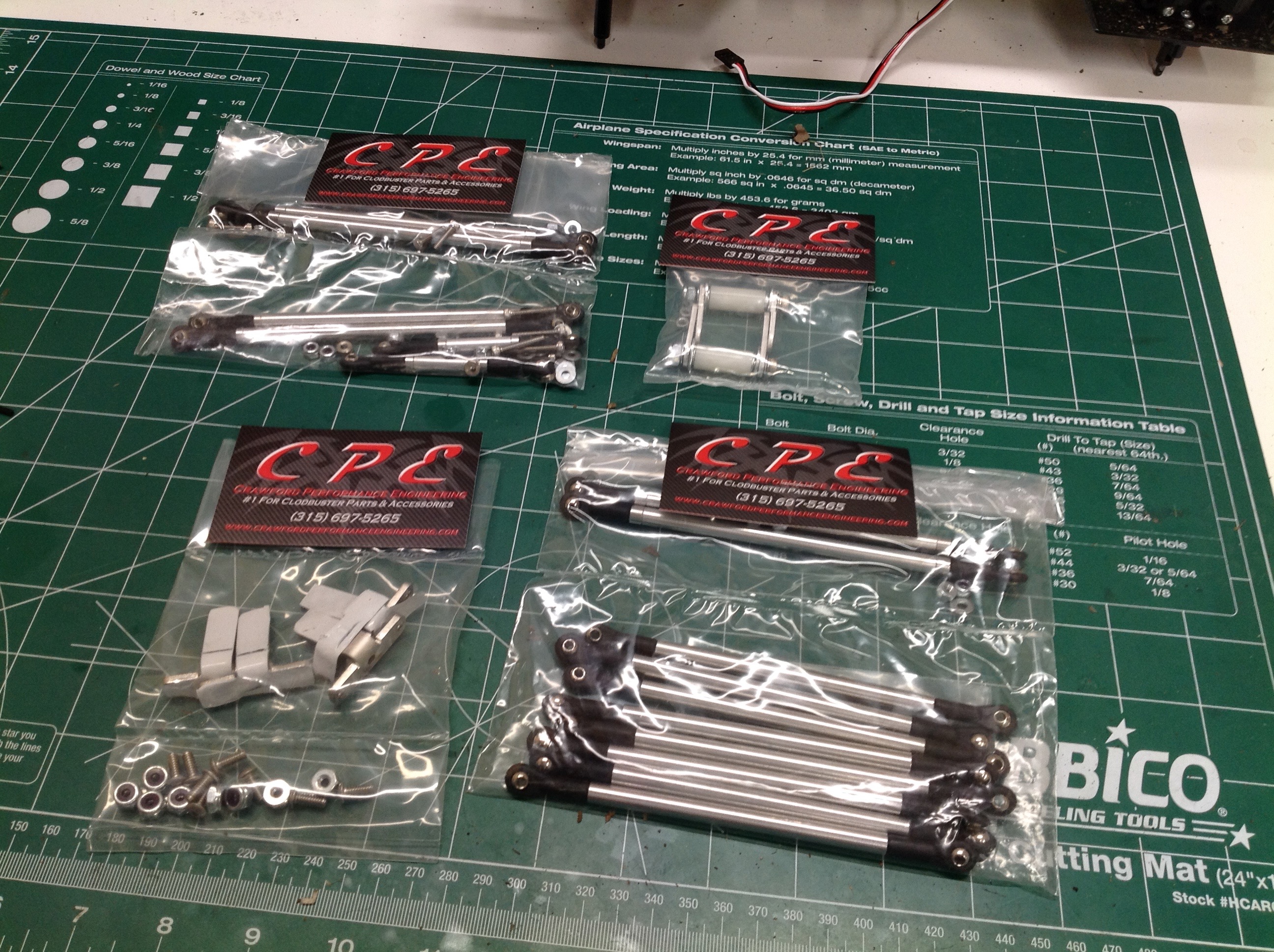
a Clod, but I finally found some parts at CPE (Crawford Performance
Engineering) that I thought kept it close enough to stock while
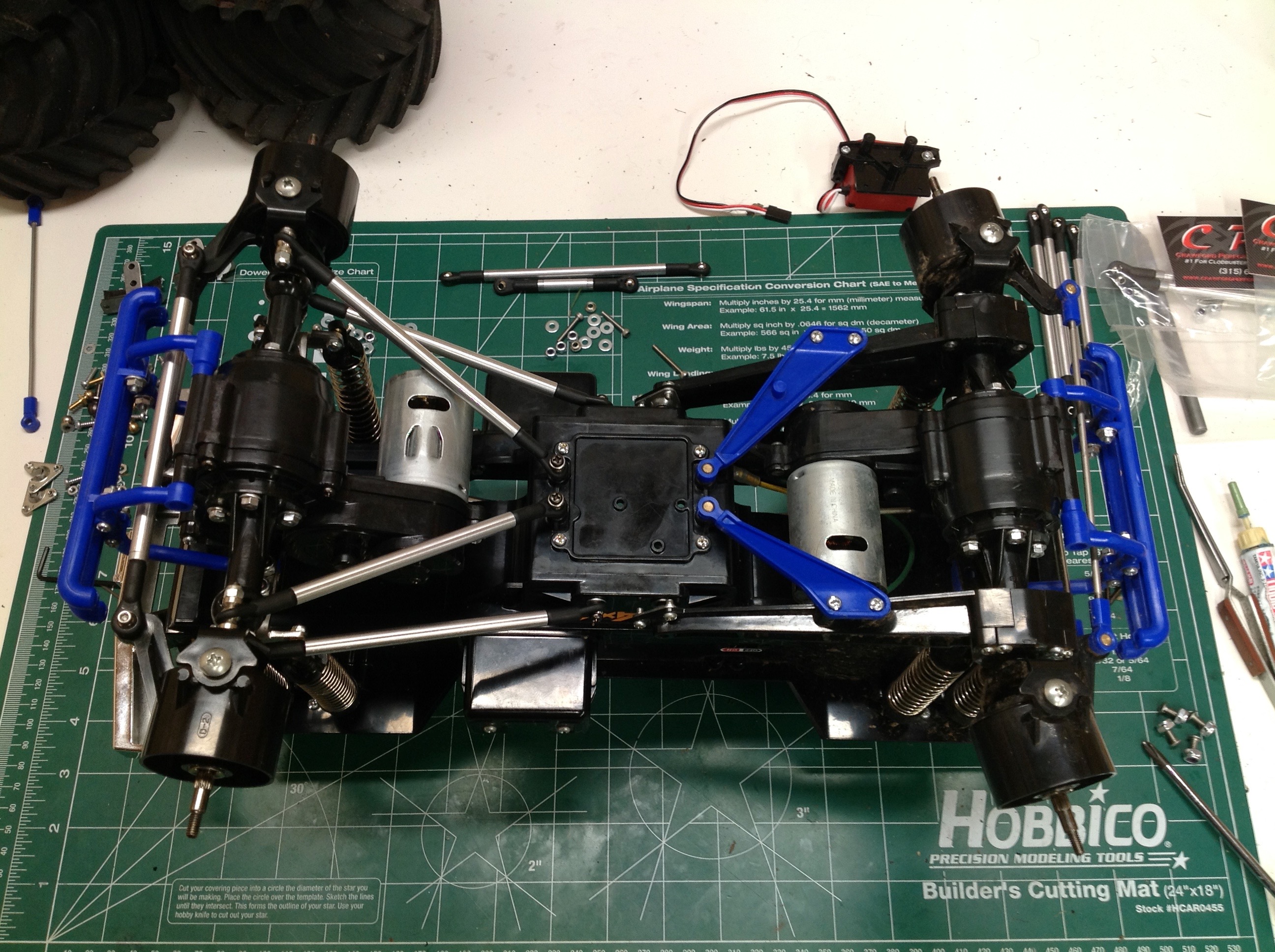
addressing some of the more serious issues. The picture above just
looks like a pile of links, but there is a lot more going on here.
This step took me several hours. I tore off the original plastic
suspension links and replaced them with a real 4-link suspension. I
also replaced the steering tie rod and servo link with much stronger
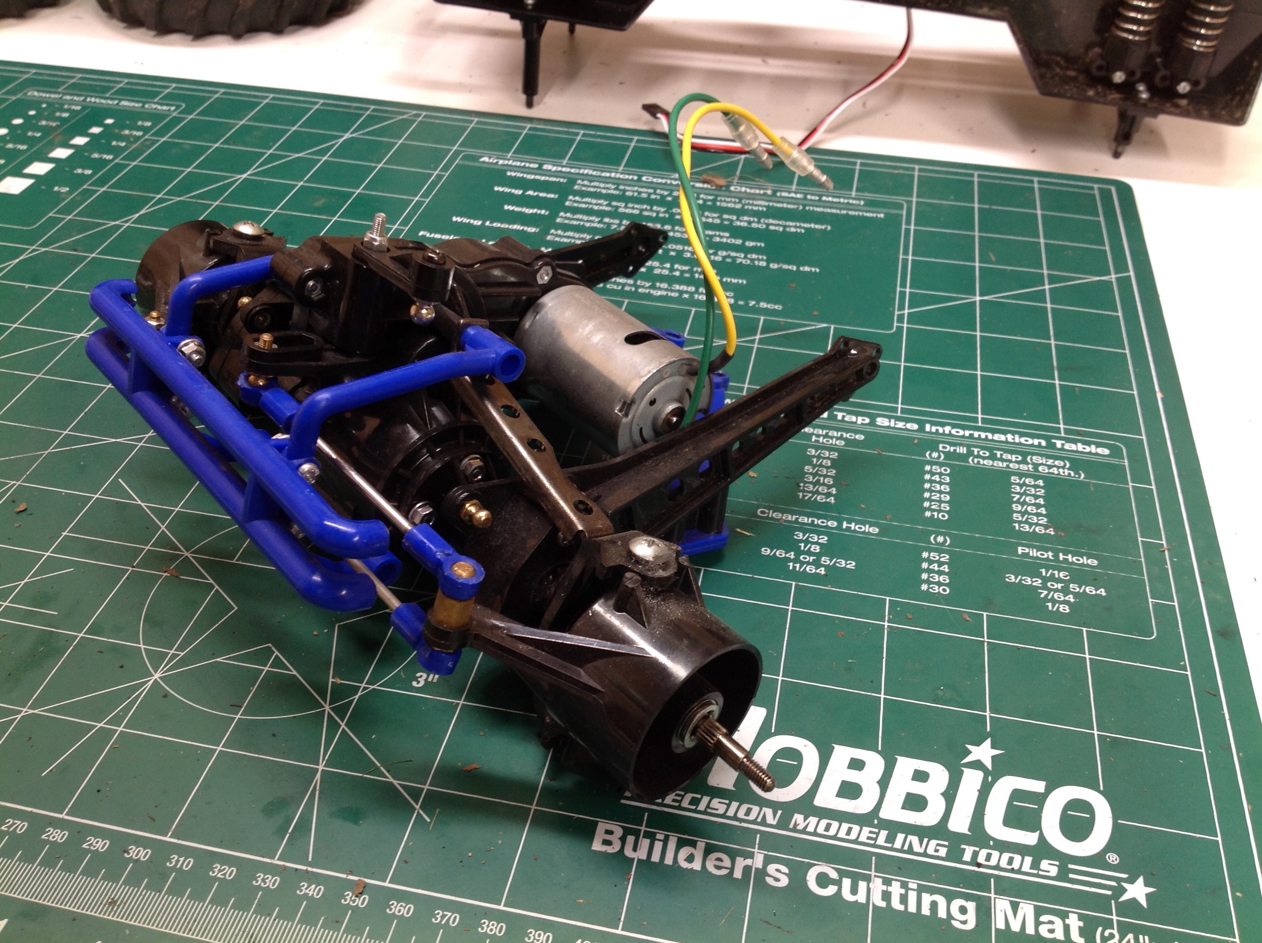
versions. But most importantly I replaced the mushy servo saver
with an aluminum version. This system has no springs. Rather
it is a solid connection, but it is only kept solid with friction so it
can slip if enough pressure is applied. It needs to be quite
tight to steer these heavy wheels. You can also see the new
shock mounts which are quite a bit higher than the old versions which
were connected to the lower link. This give some welcome extra
clearance to the servo links.
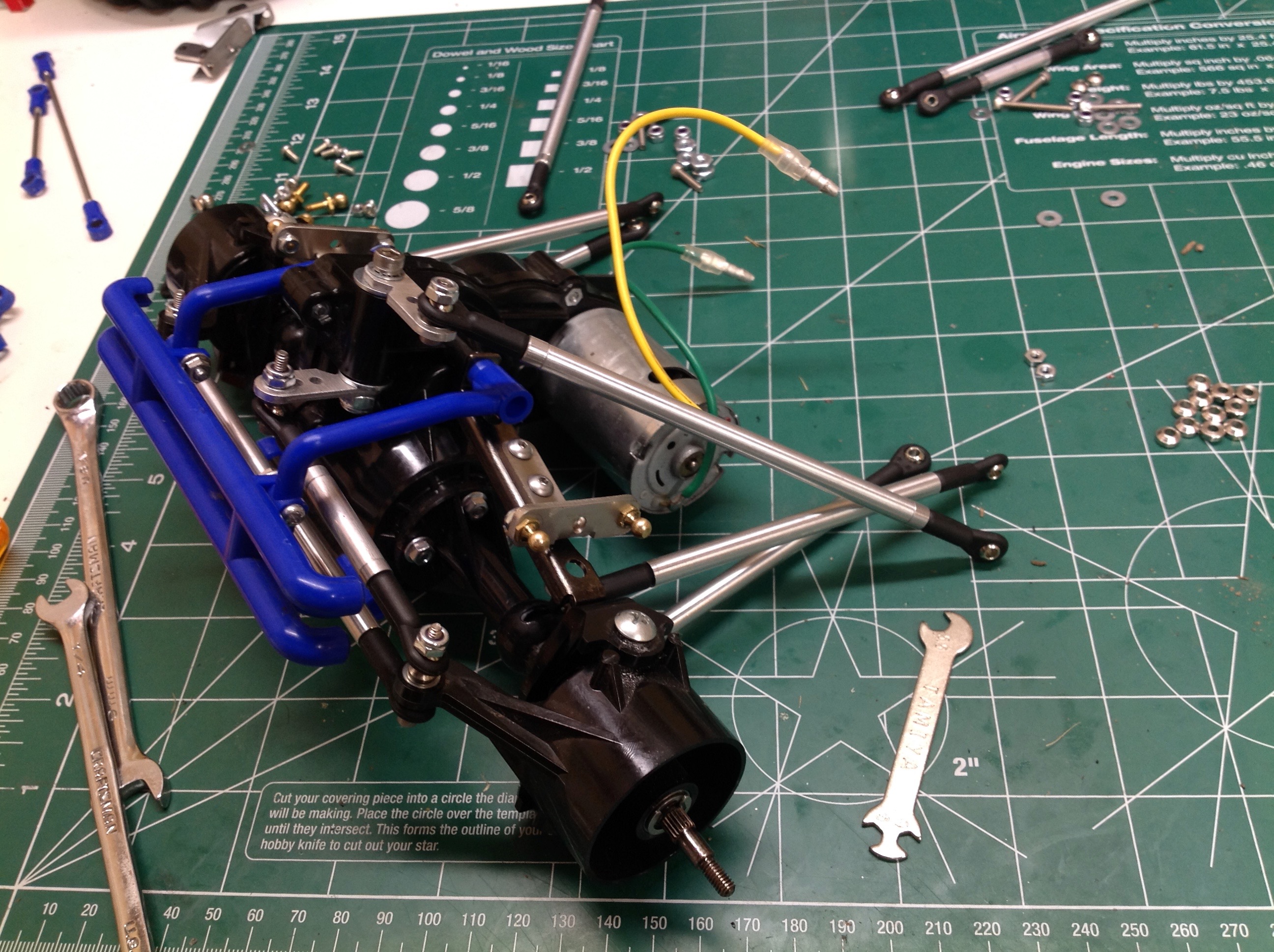
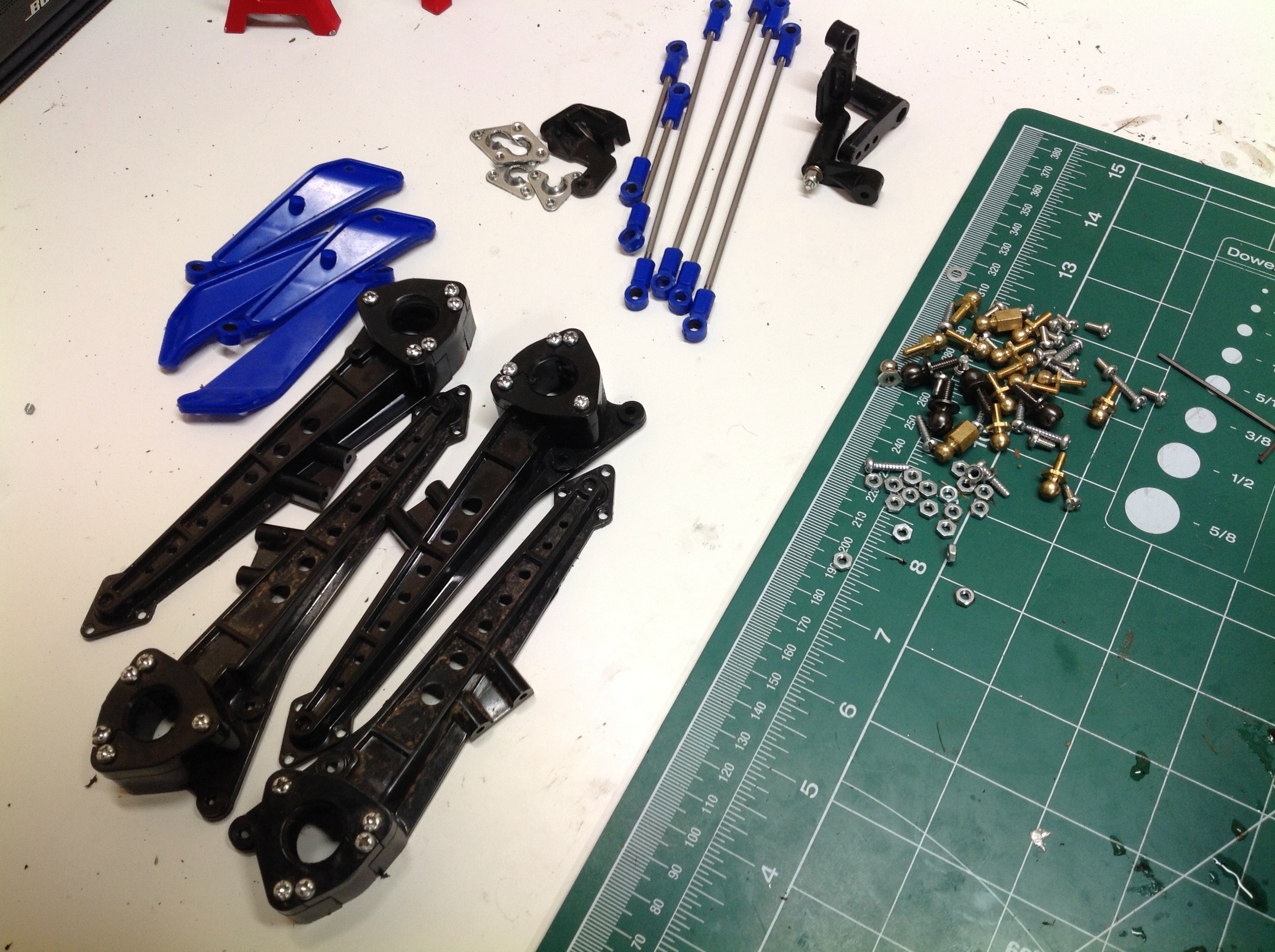
Here we can see the new system installed on the front with the old
system on the back. The difference is substantial. The
original suspension is not a true 4-link because the lower links are not
independent. Instead they attach to the middle of the upper links
and provide lateral support. The new system is a real 4-link
which allows more motion. The right hand image shows all the
replaced parts.
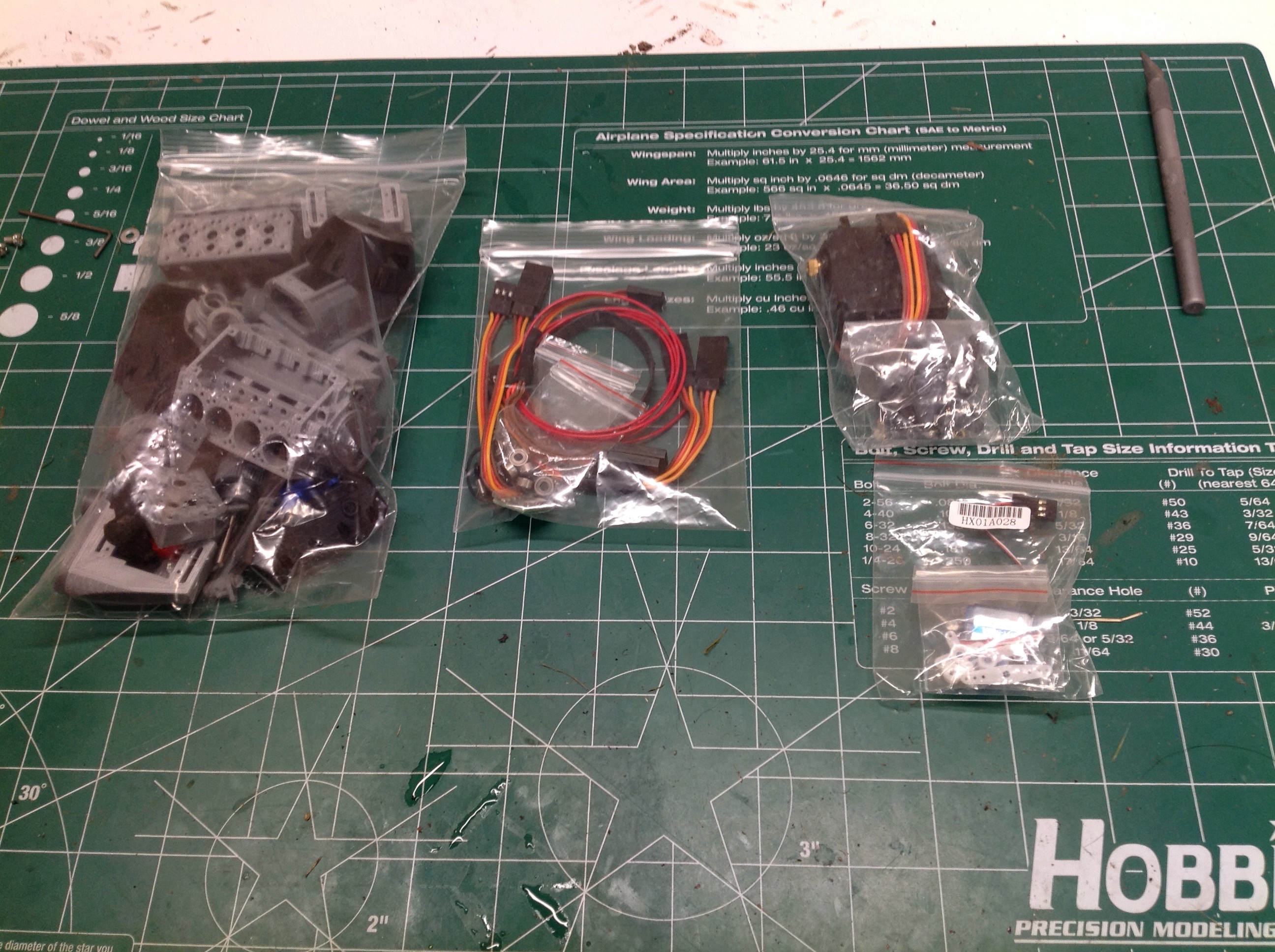
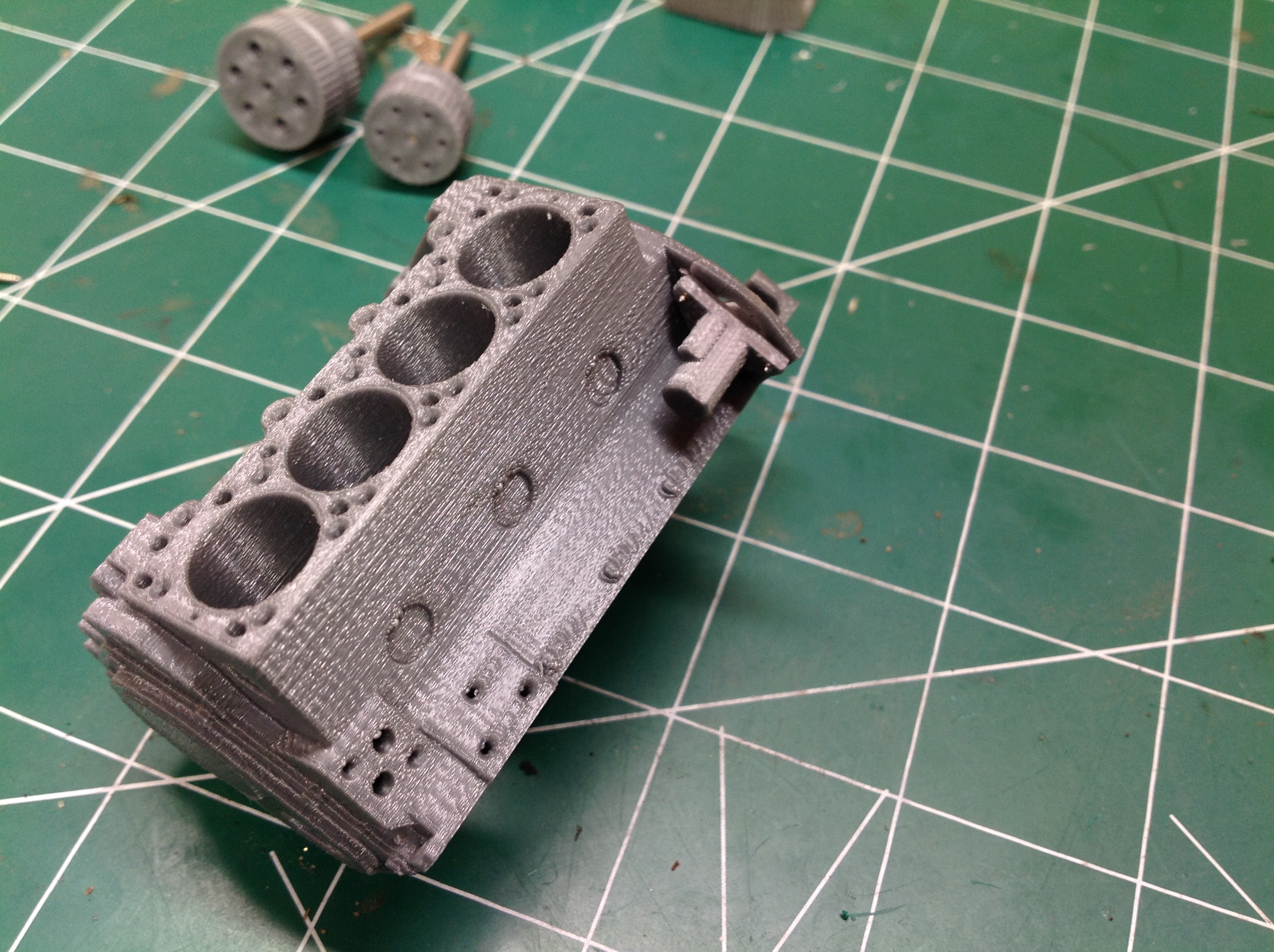
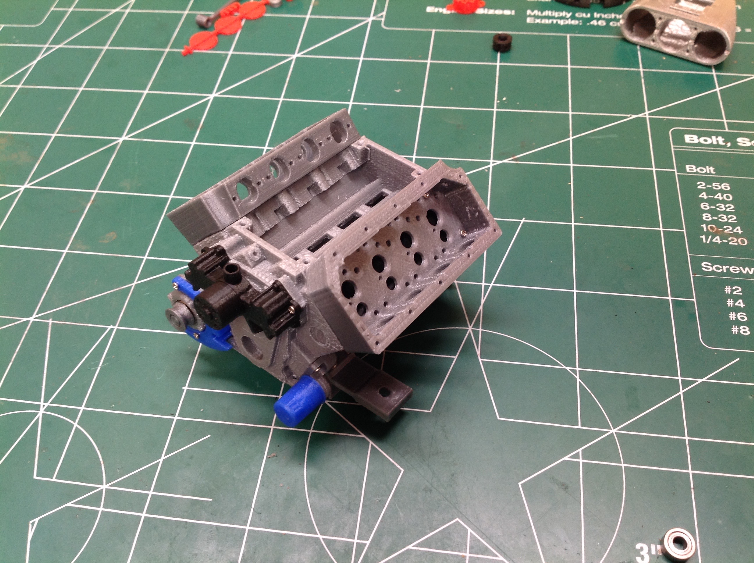
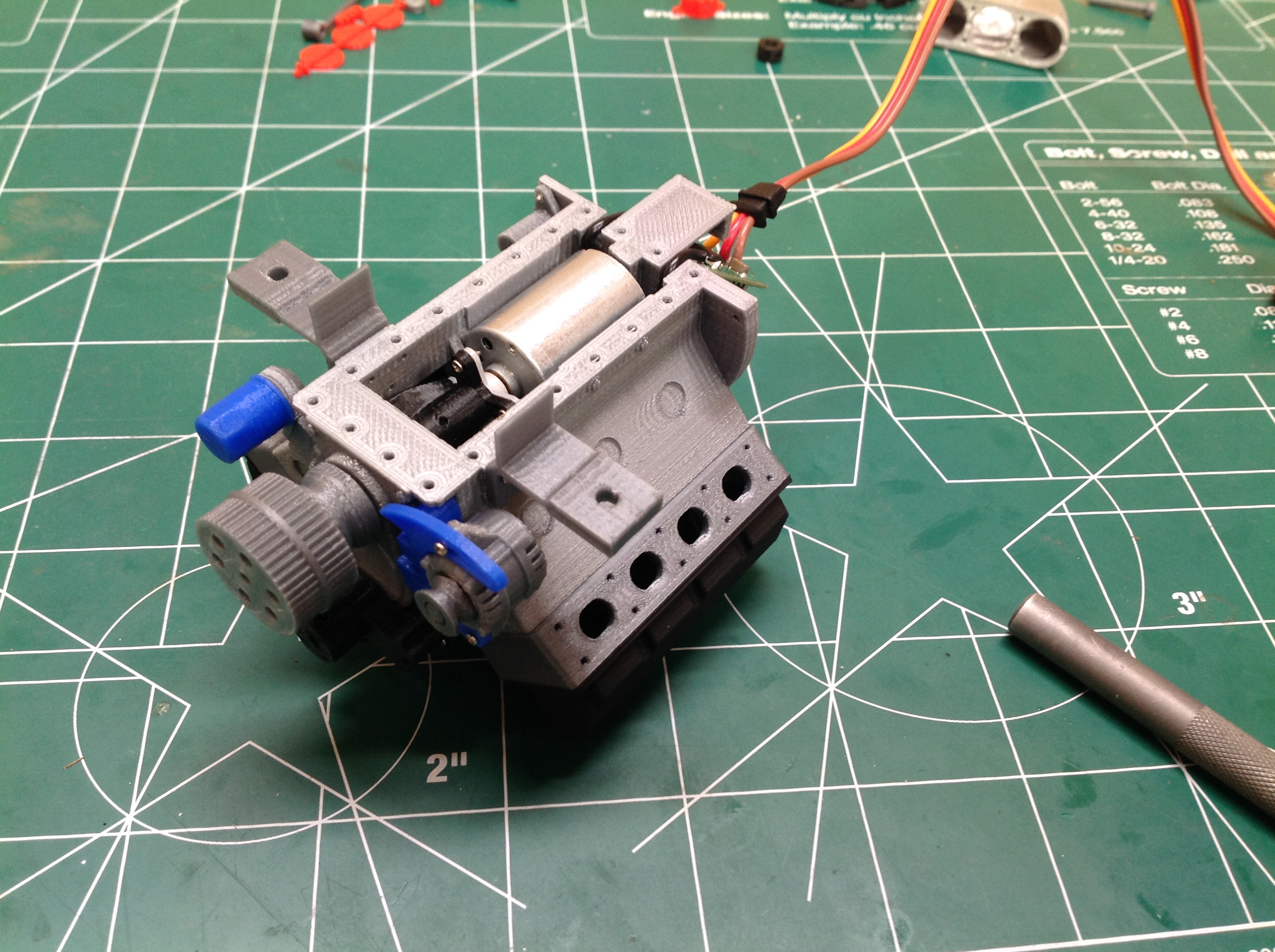
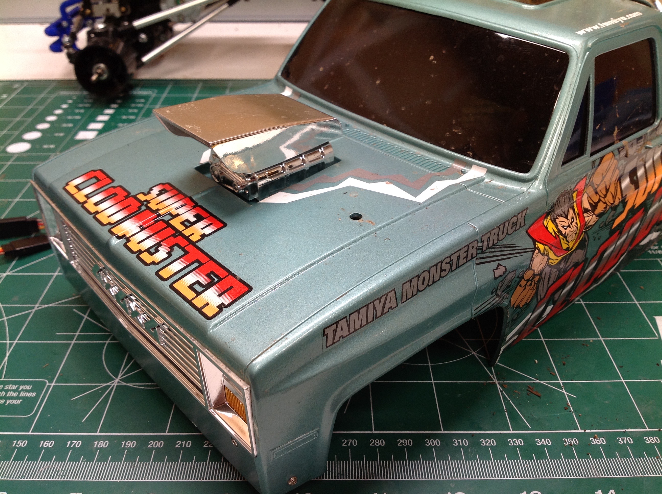
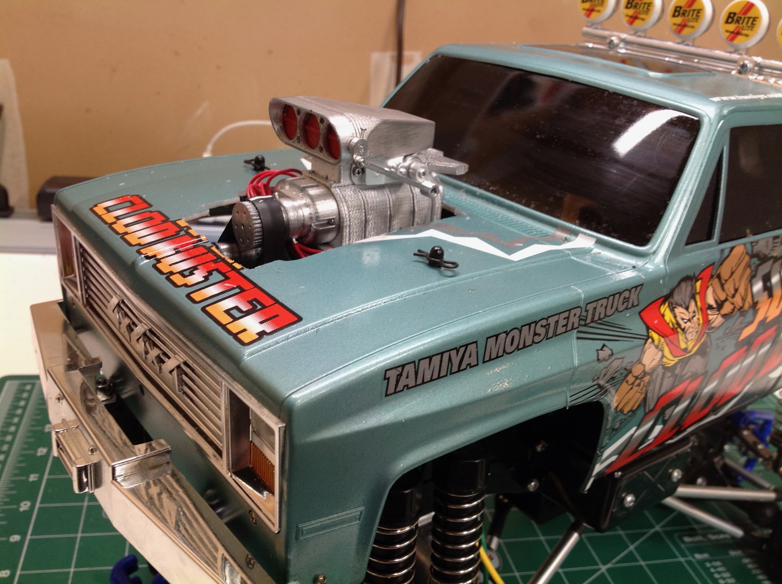
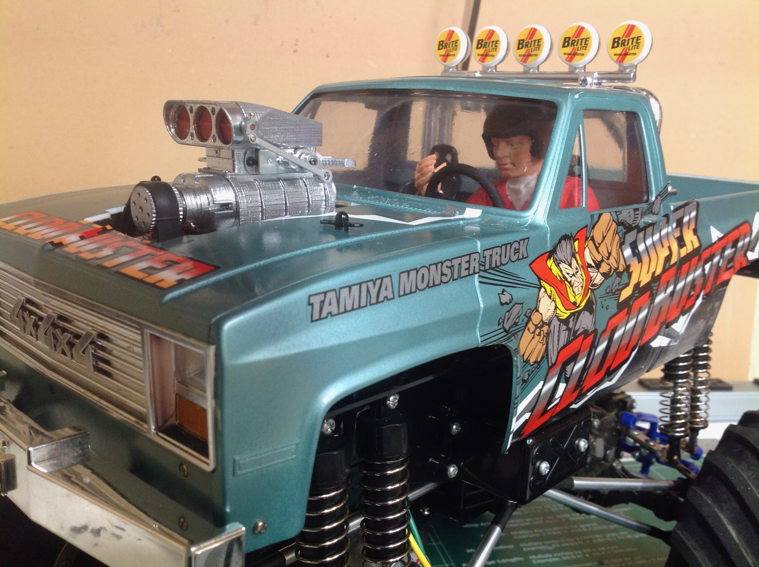
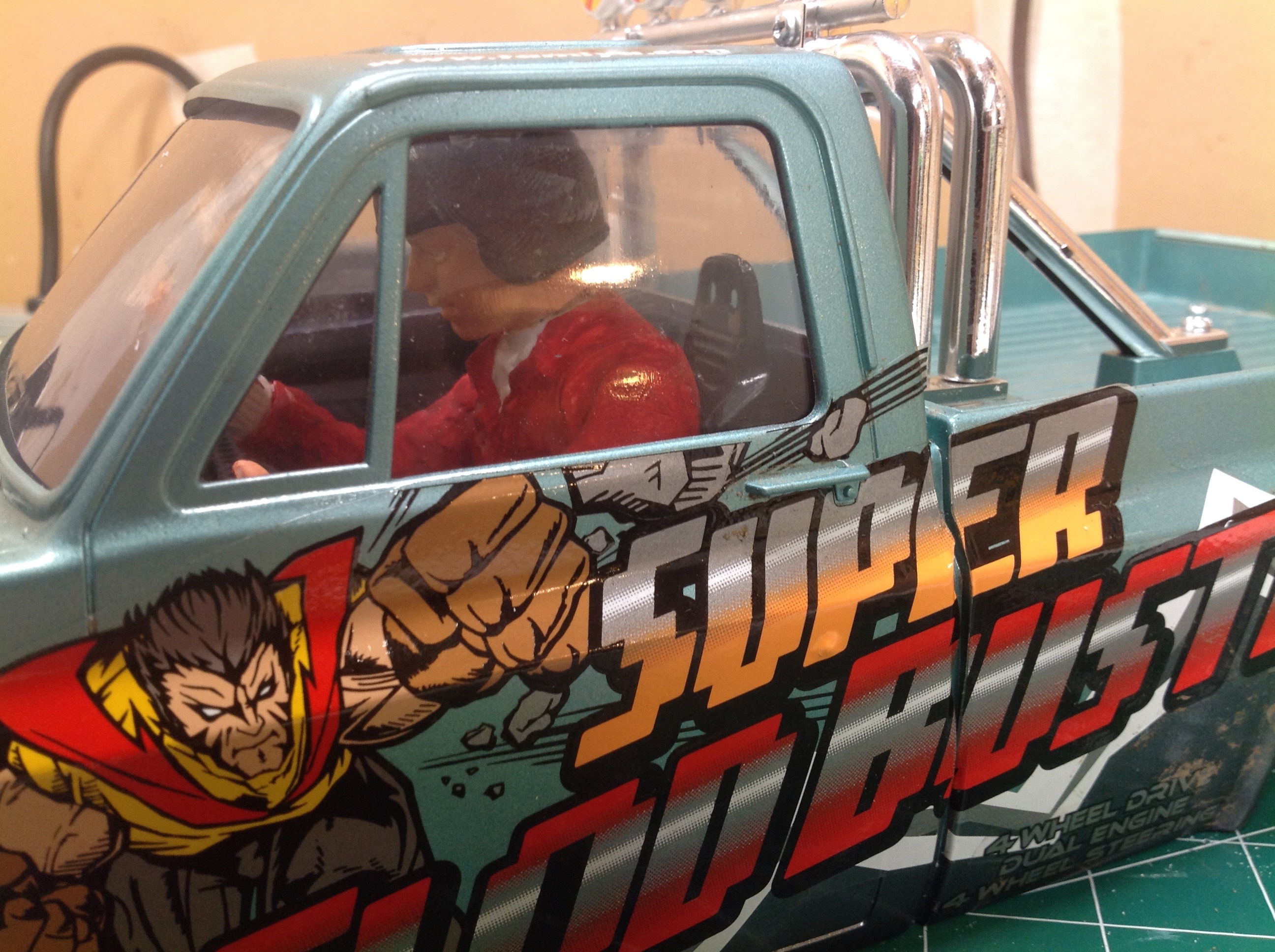
Next up is a 3D printed supercharged V-8. I bought this a while
ago off of eBay because it was so cool and I had been trying to find a
home for it. The Clod Buster already has a fake blower sticking
out of the hood and plenty of room in the front of the chassis so it
seemed like a good home. I can't believe how much cool stuff comes
in this kit. Dozens of 3D printed parts, a bag of hardware, and 2
servos. Everything you need to built a (fake) working V8.
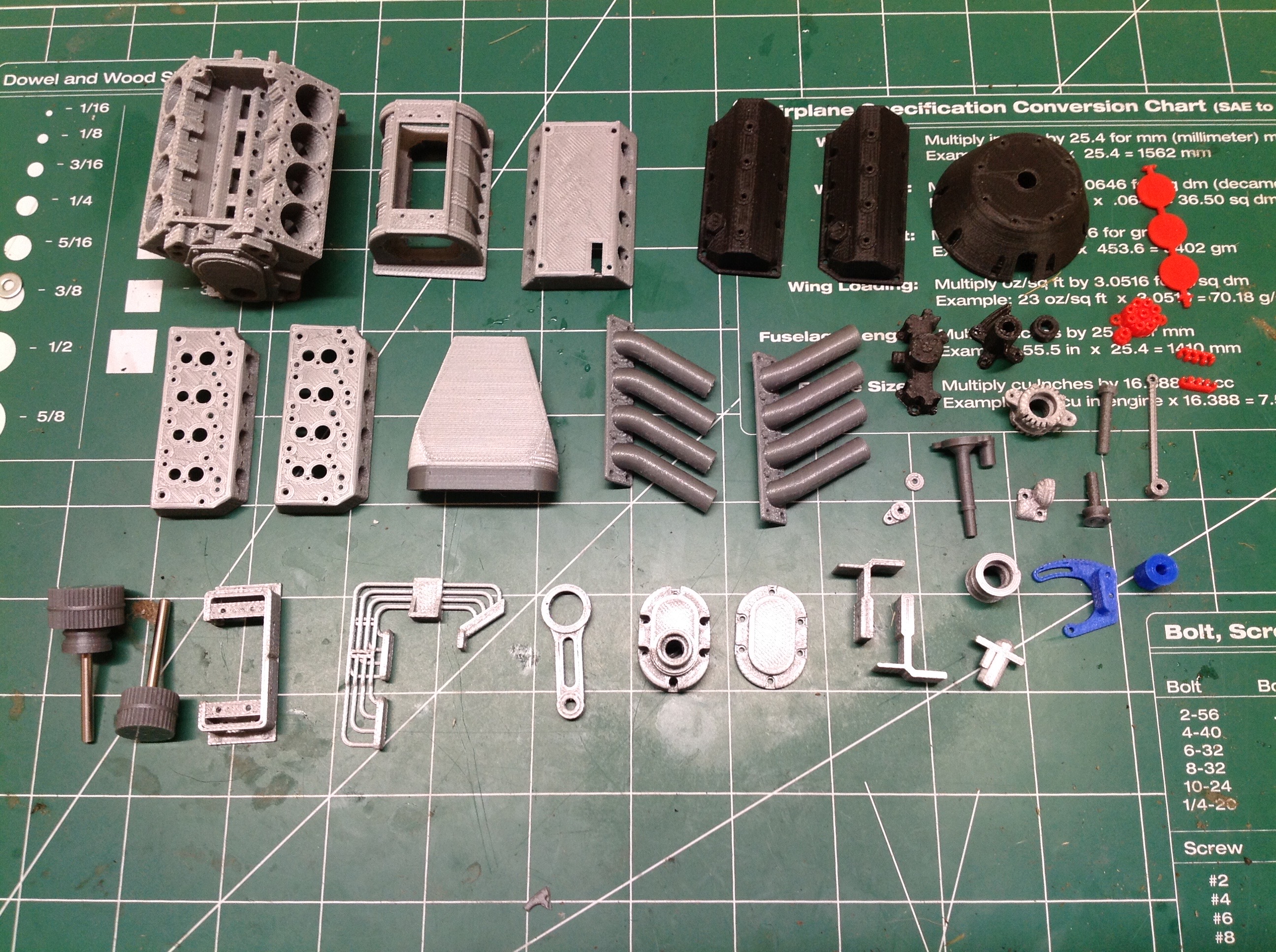
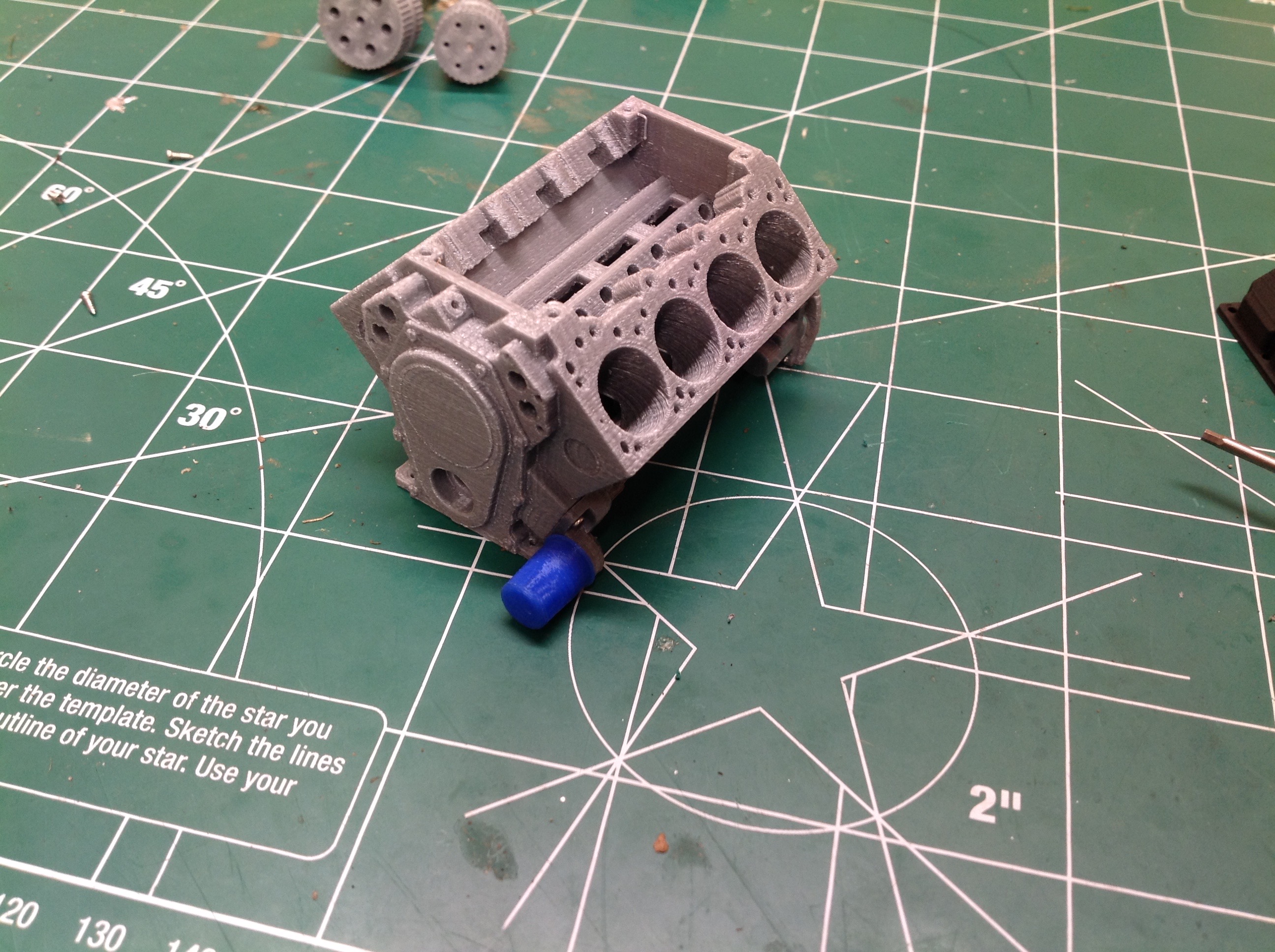
First step is to attach the starter to the block. Yes, this thing
is detailed enough to have a starter. Next step is the oil pump
and filter. Note that the cylinder bores are purely ornamental;
nothing will go into them. There are no pistons.
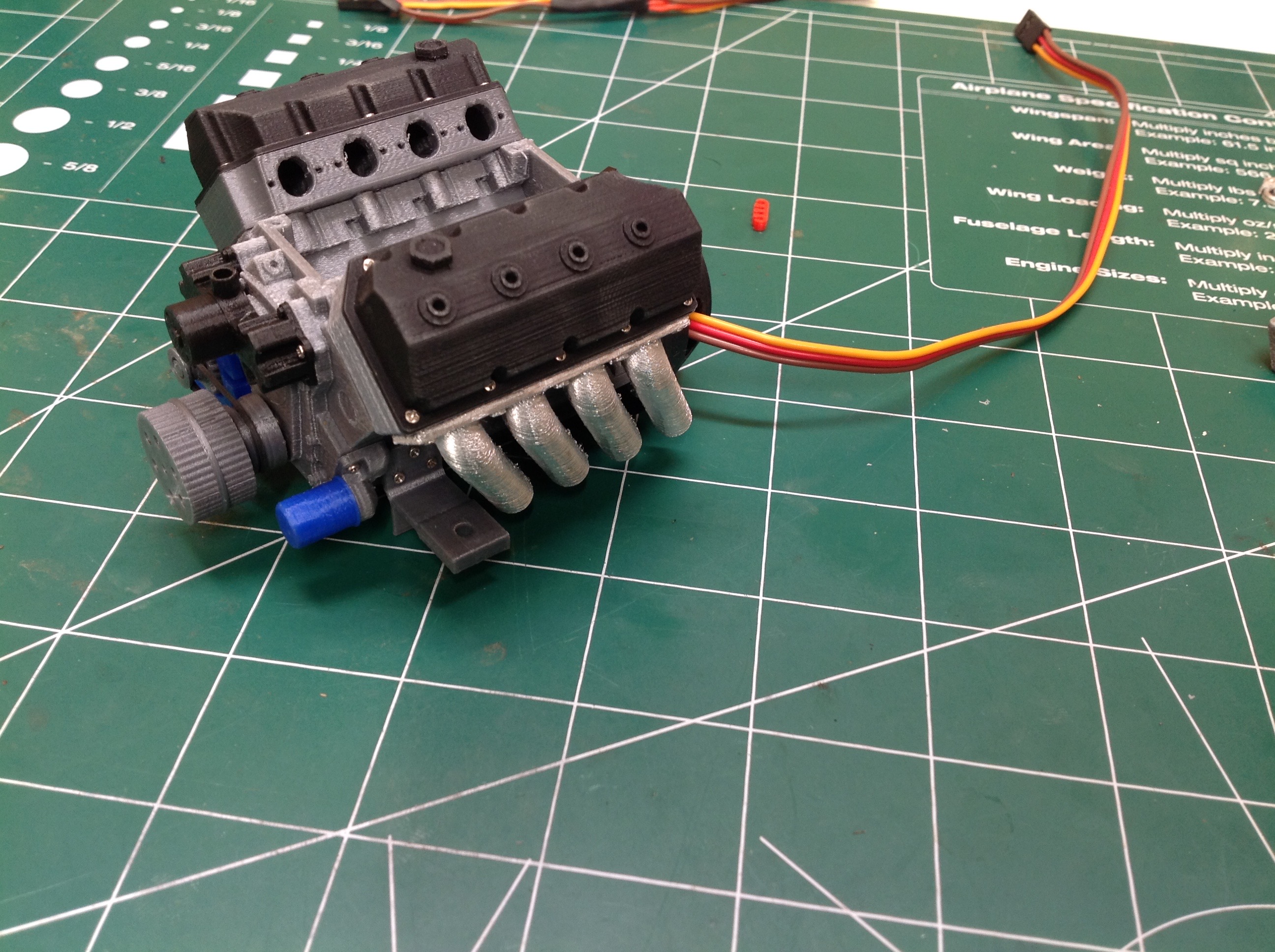
Now I attach the water pump to the front of the block followed by the
alternator and its support bracket. There is no timing chain.
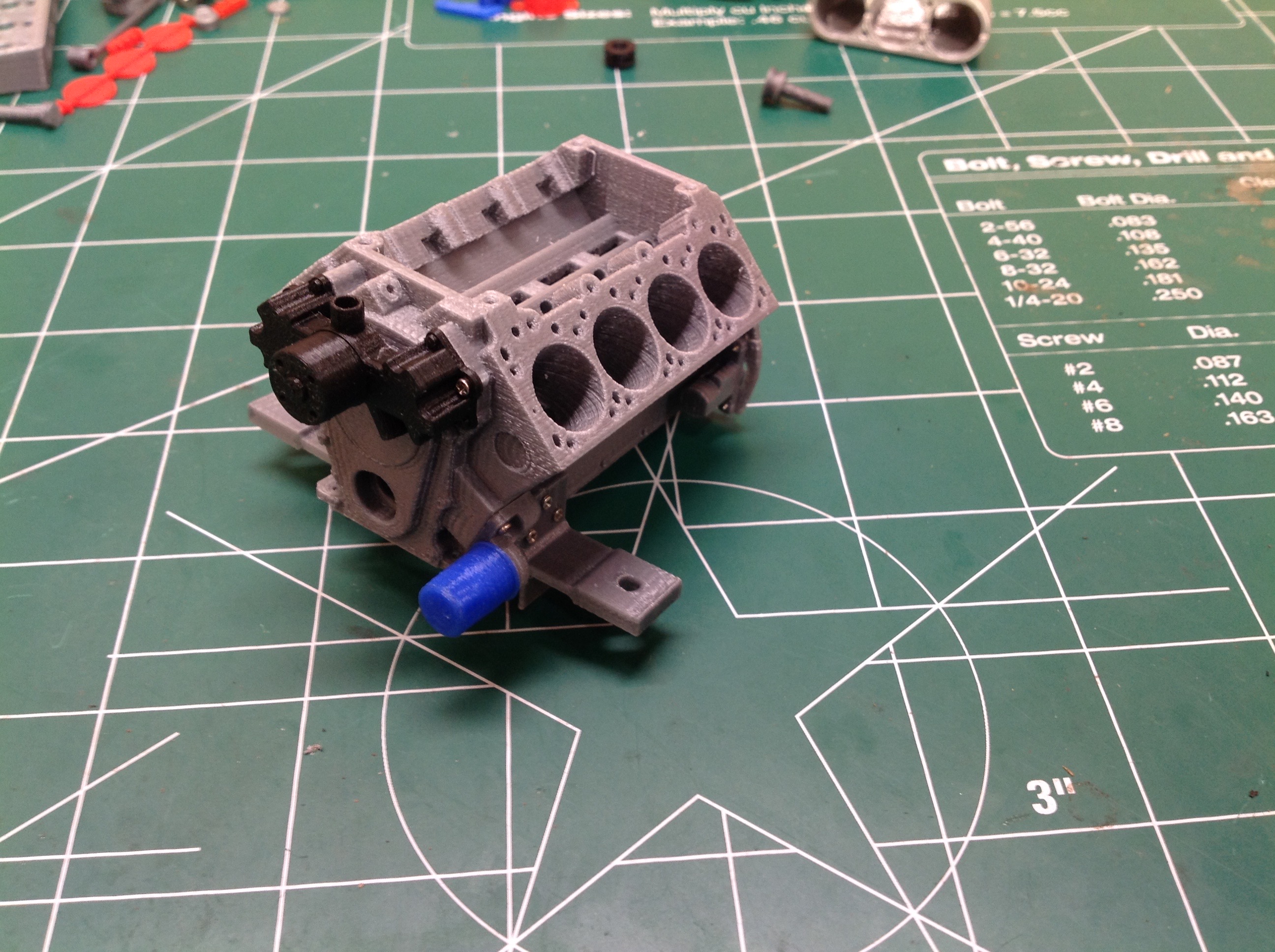
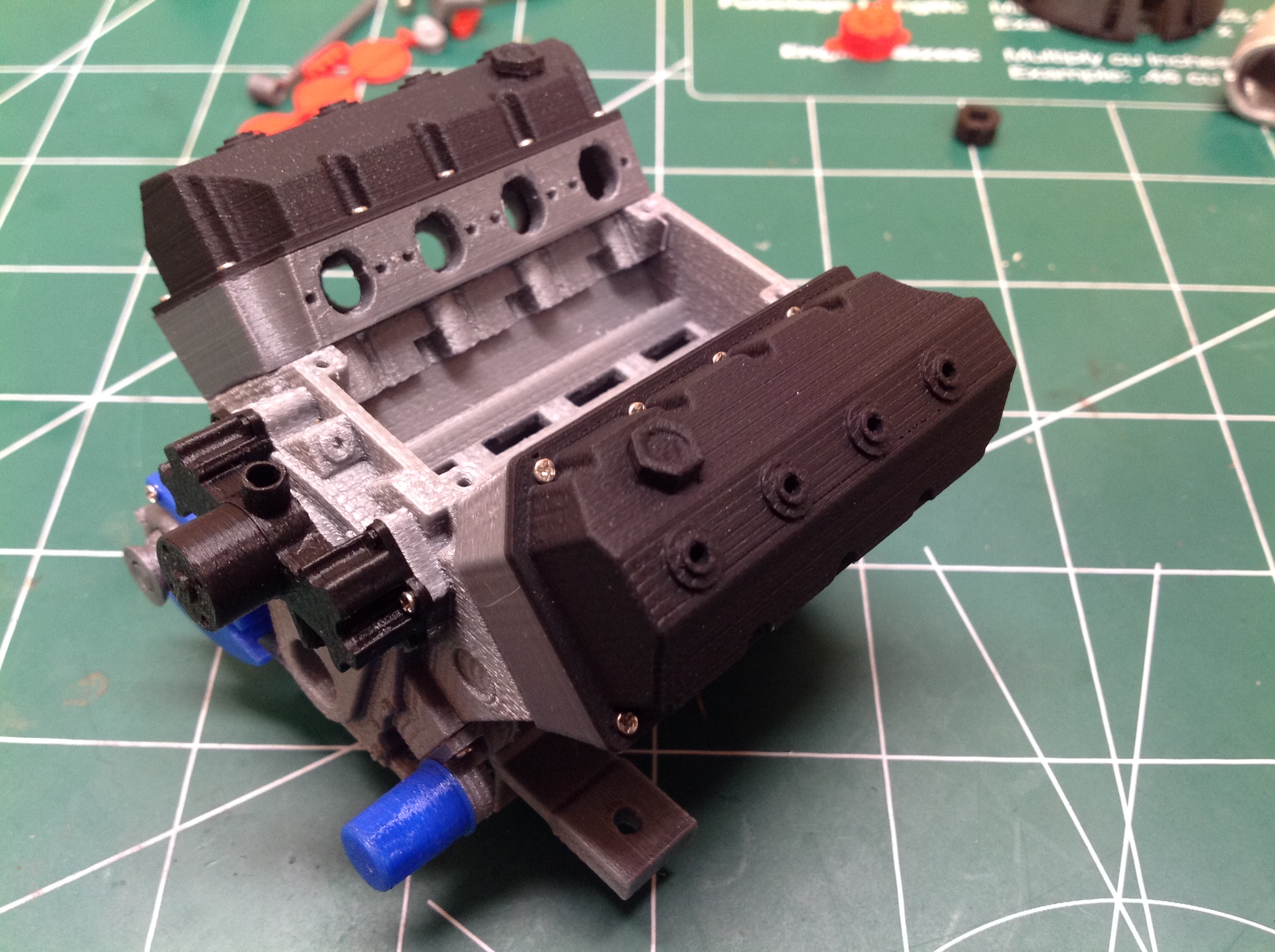
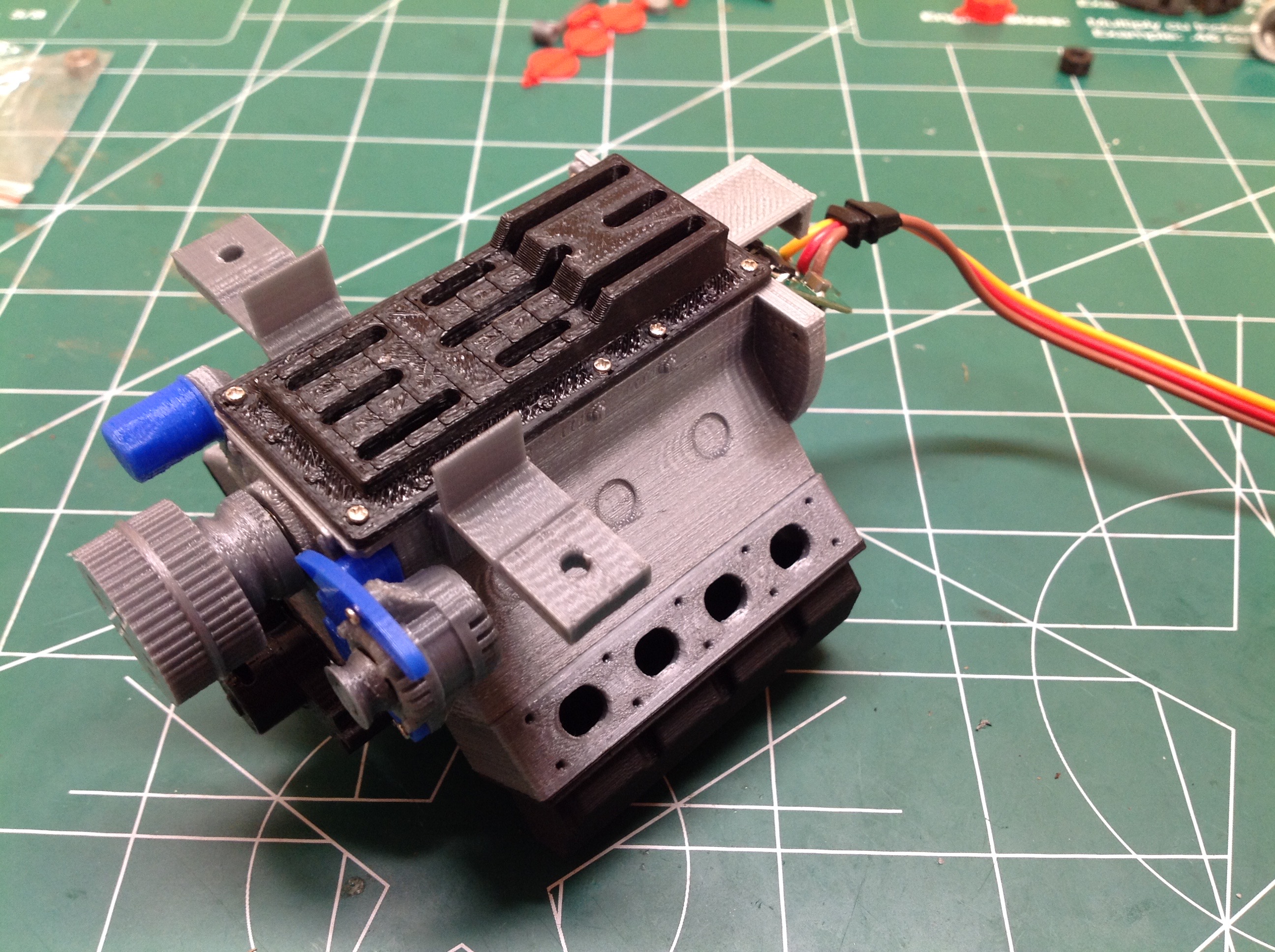
Next up is the heads and then the valve covers. This is certainly starting to look like an engine.
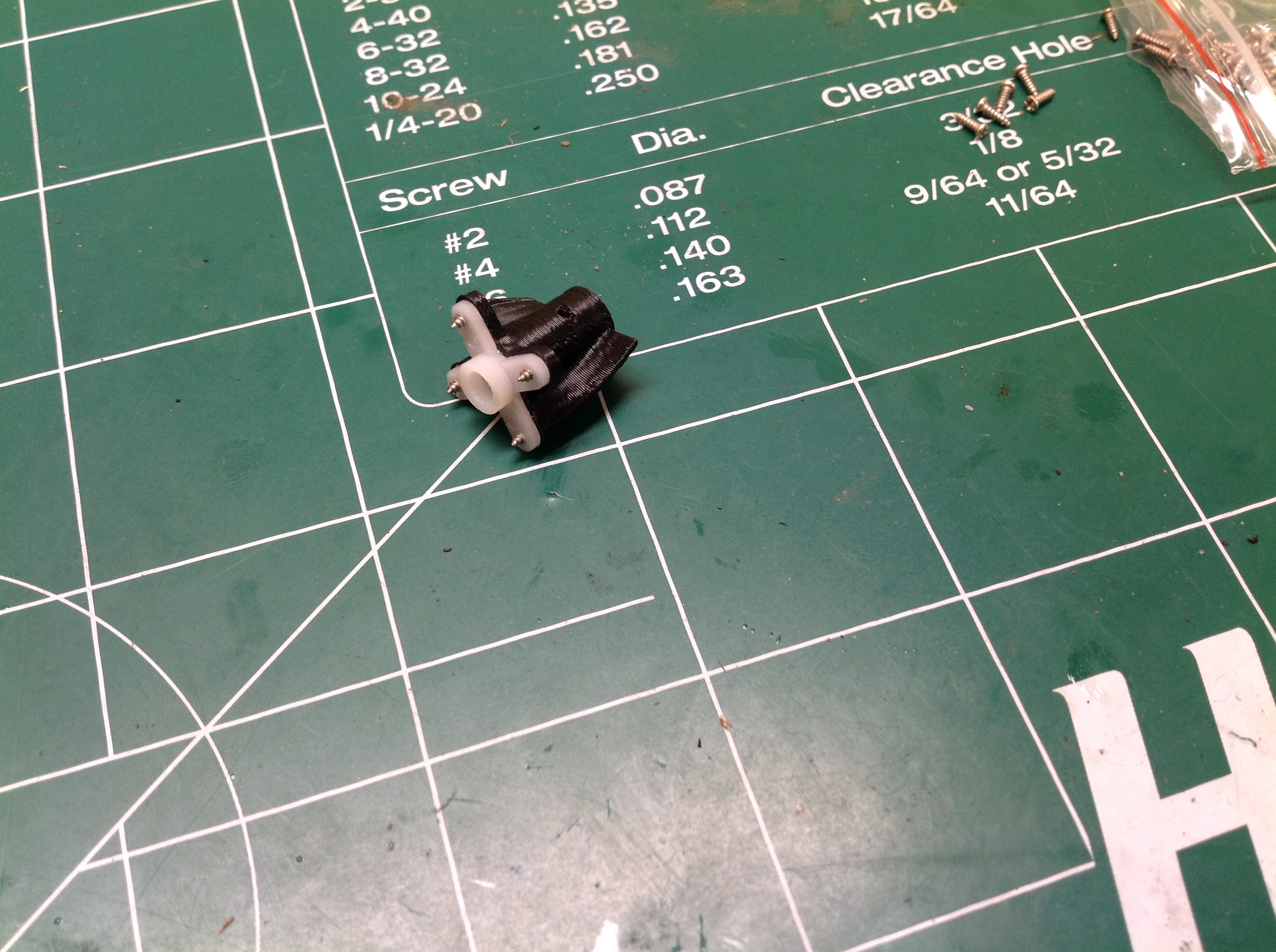
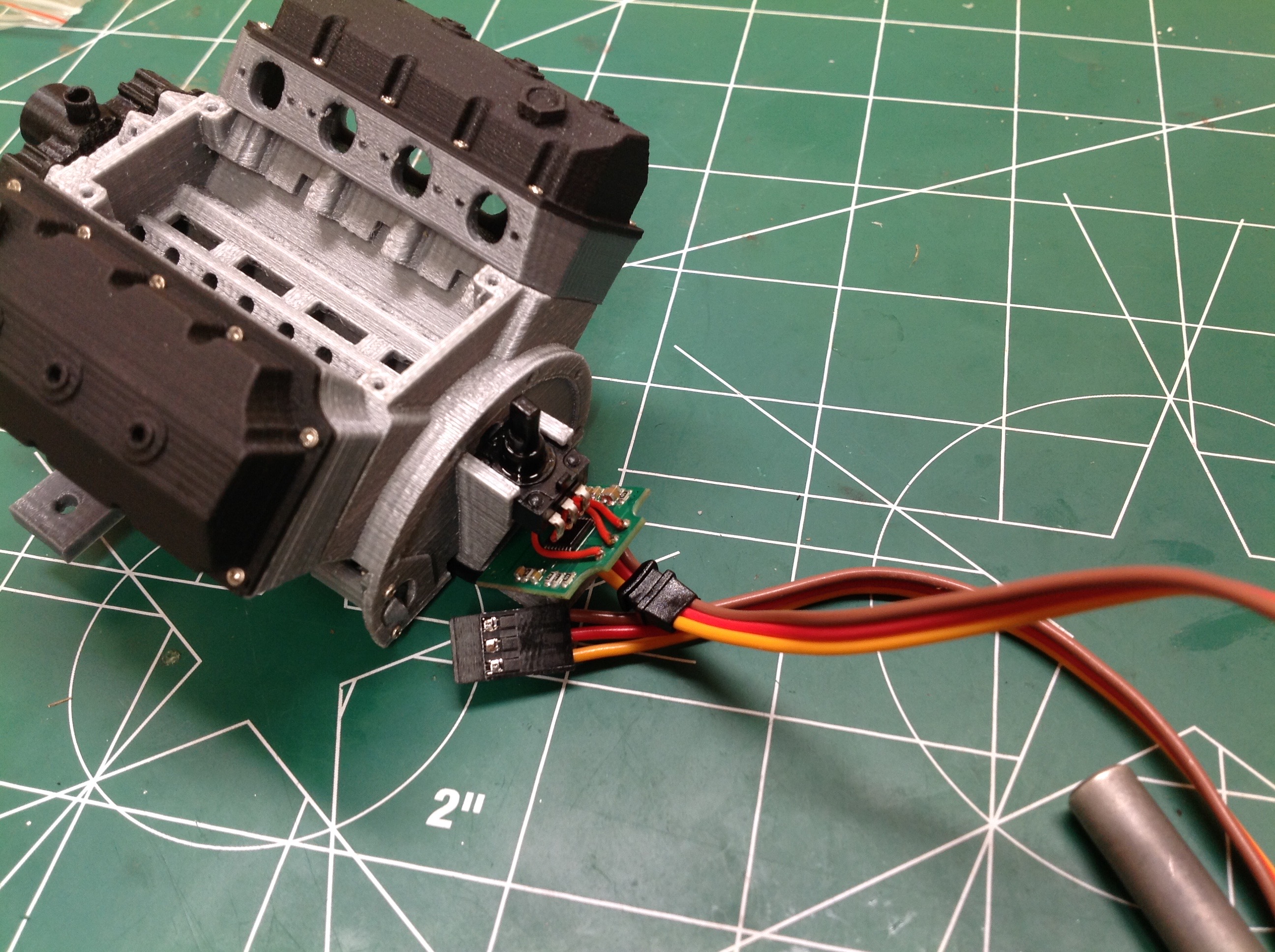
Now we'll start to put some electronics inside. At first I thought
this was a supercharger impeller, but it is actually a little fan to
cool the motor. The motor is extracted from a full size
servo. The potentiometer is used to set the idle speed by telling
the servo it is a little bit off center. The throttle can then be
used to rev up to full speed. A very clever solution. The
4-sided control horn from the micro servo is re-used as a connector for
the fan and then pushes onto the gear of the servo motor.
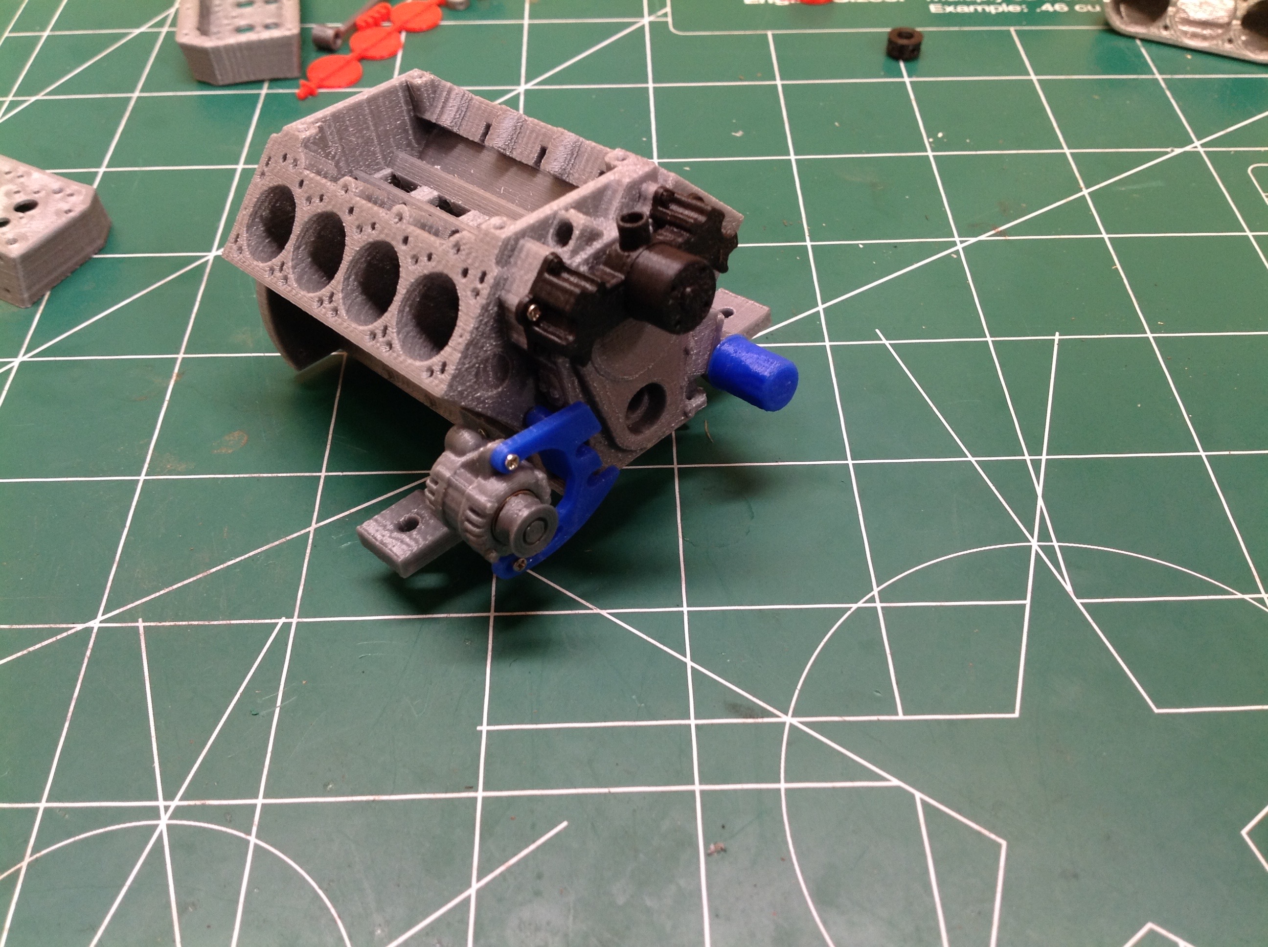
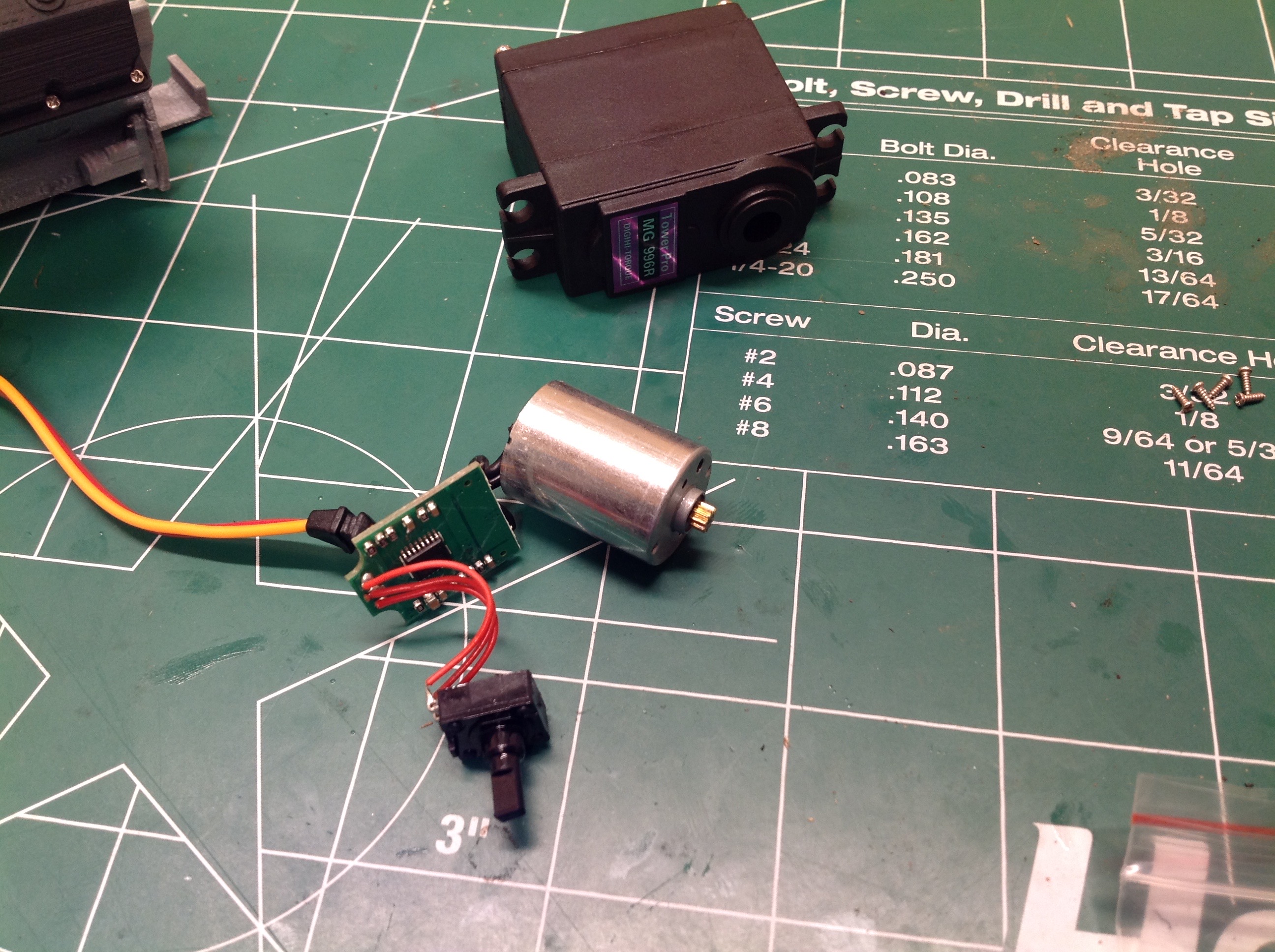
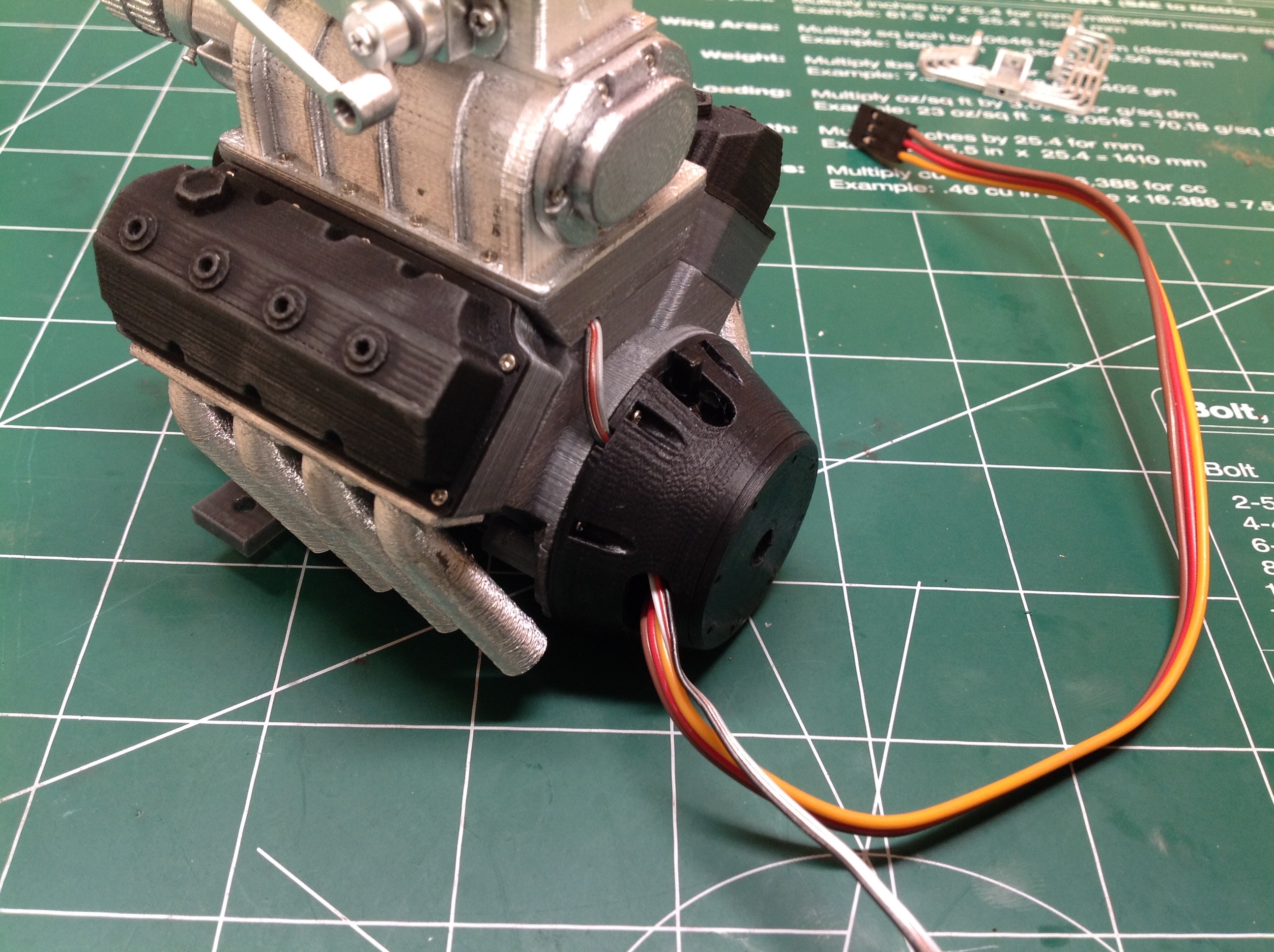
From the bottom you can see how the servo motor directly drives the
lower pulley which would be the crankshaft connection. We then add
some motor mounts and an oil pan which is slotted to allow cooling the
motor. Servo motors are not really designed to run continually,
and I don't know how this one is going to hold up.
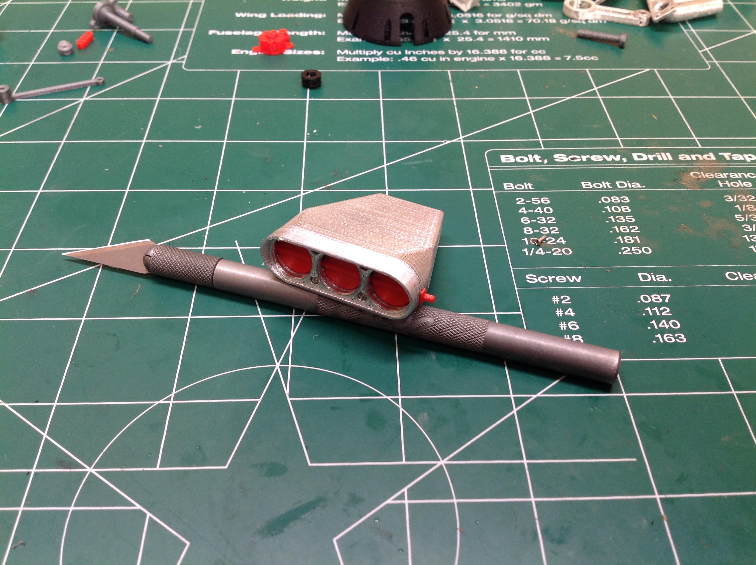
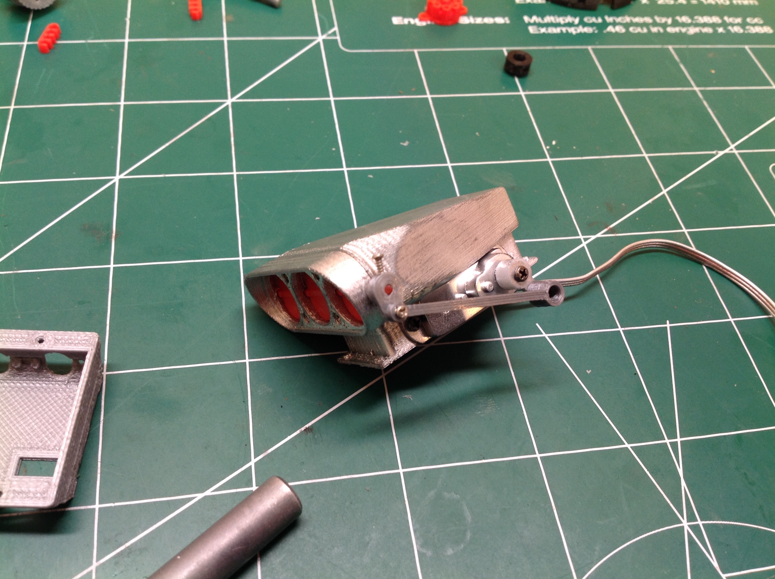
Here's the air intake for the supercharger. The butterfly valves
can pivot to open and close. A micro servo (here painted chrome)
is installed on the bottom with a small servo horn protruding.
A tiny arm connects the servo horn to the butterfly valve which allows
it to open and close. At idle it will be closed and it will flare
open as a function of throttle position. The upper drive pulley
has also been installed to the intake manifold.
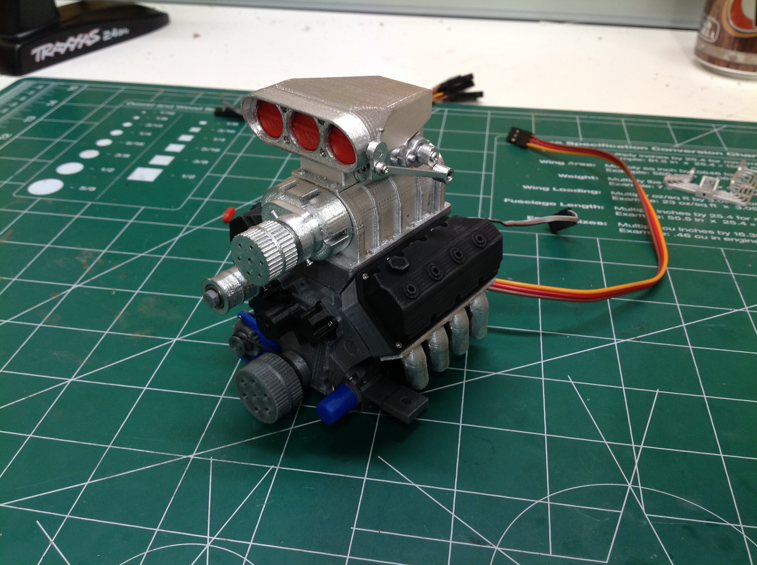
Now the exhaust manifolds have been installed. There are several
styles available. I chose these because I didn't want to cut so
big a hole in the hood to allow vertical pipes. In the right hand
image the intake is installed.
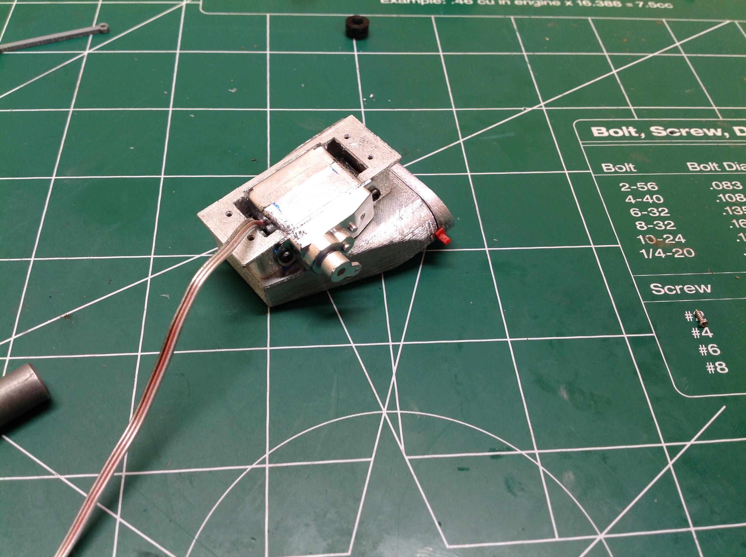
From the back of the engine you can see where the pot sits and how the
PCB is tucked away. Once the bell housing is installed all of this
is hidden but you can still access the pot to control the idle speed.
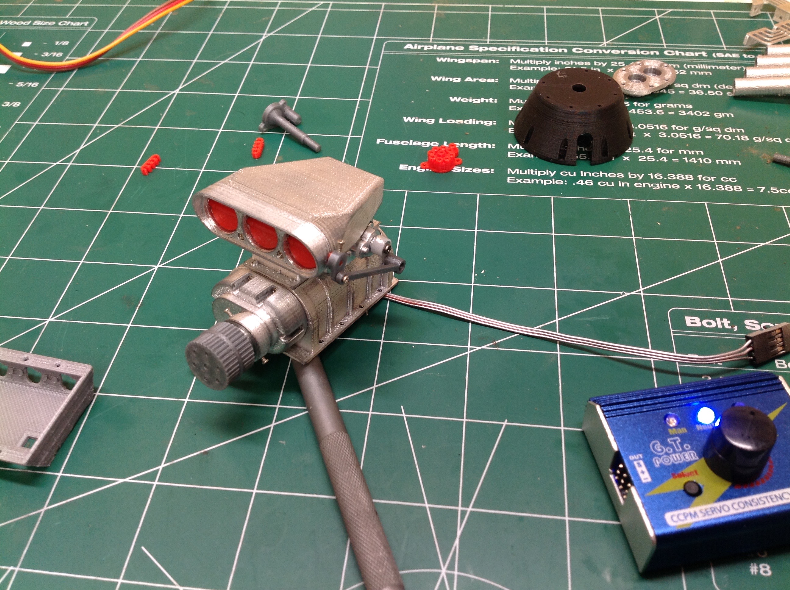
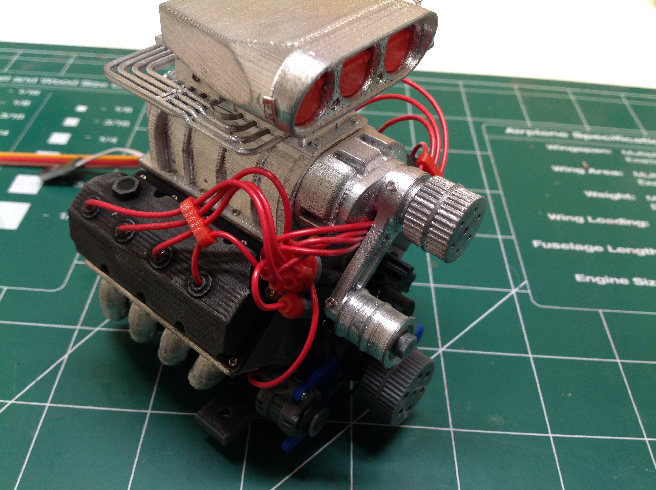
Now the fiddly bits: the spark plug wires. I actually found
installing these kind of relaxing. The instructional video made it
all quite clear, and I love how neat they look once the wire looms are
installed. The image doesn't show the alternator belt or
supercharger belt, but you can see them in the following image. To
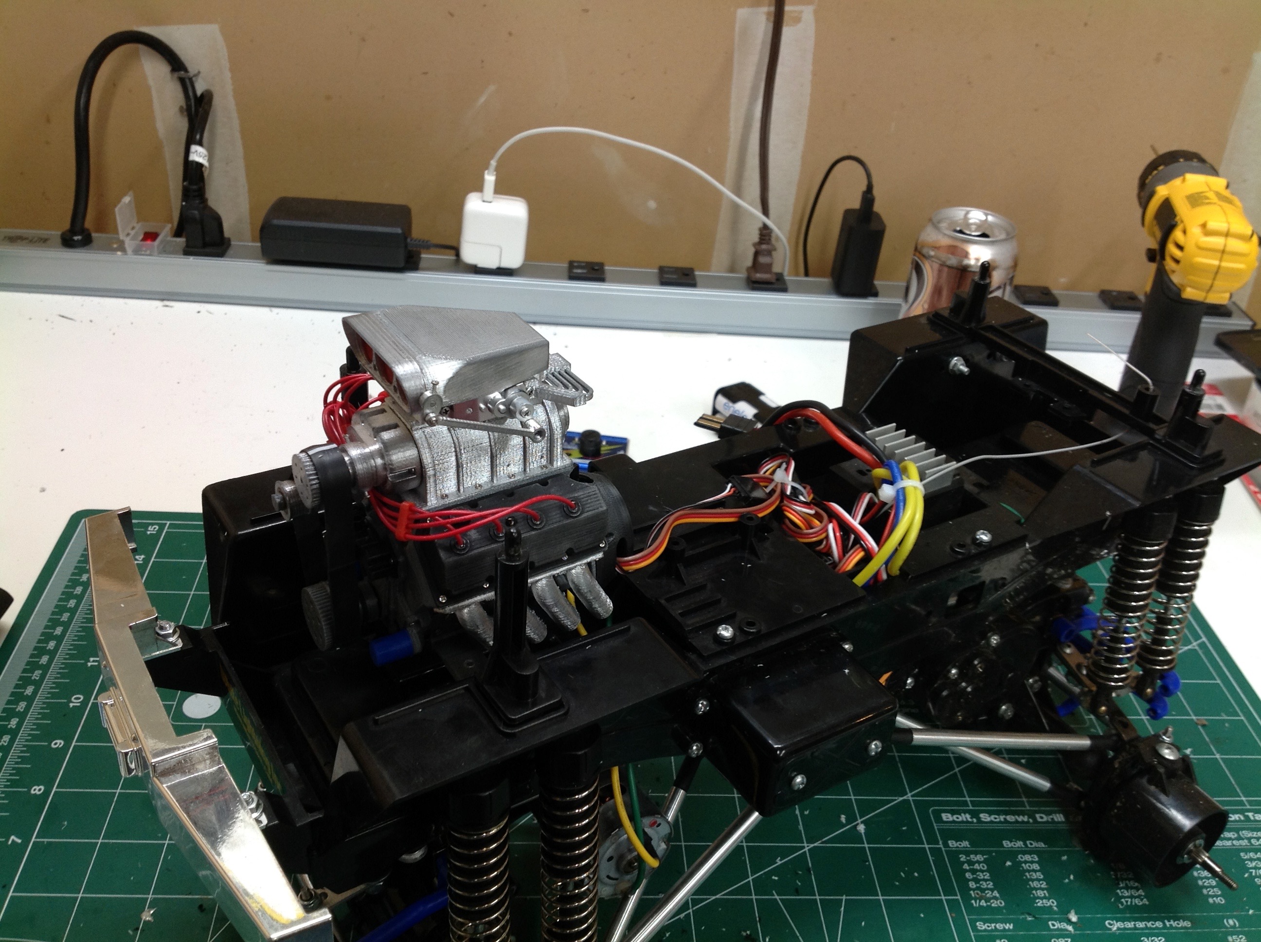
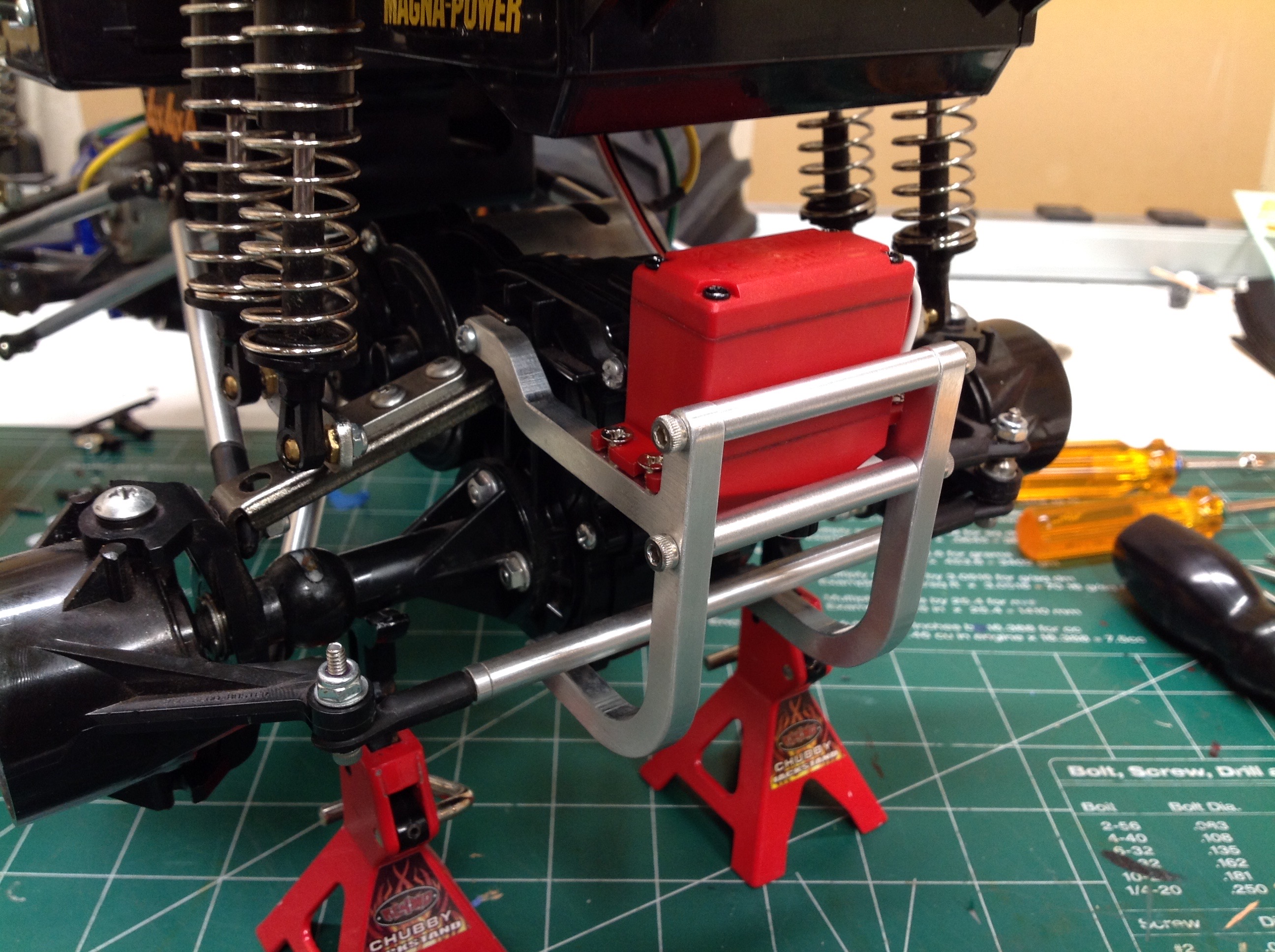
install in the Clod I had to do some thinking. I cut the cross
brace between the shock supports and attached the engine using tall
standoffs from below. I added another small support in the rear so
it wouldn't wobble since this truck is quite bouncy.
Here's the truck before and after the update. The old blower just
sat on top of the hood in a small recess. I had to cut a large
irregular hole to make room for the new engine, but it looks
great. So far I've found that the system draws a lot of power and
keeps cutting out even after I added a BEC. I probably have too
much friction somewhere so it deserves a close look.
Phase 3:
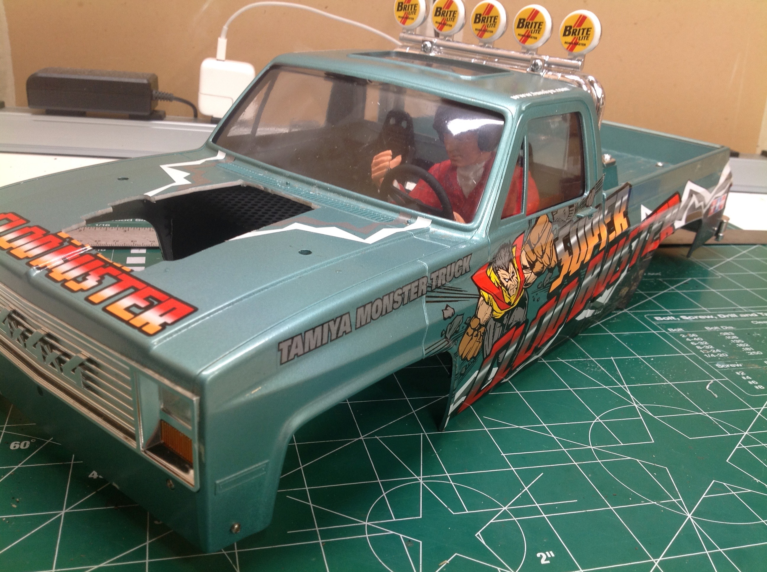
I really wanted a simple interior in this truck including a driver, and
that meant swapping out the stock tinted plastic window with a clear
polycarbonate version. Luckily I found just the thing at RC4WD.
The installation couldn't really be any easier. Unscrew the old
one piece window and screw in the new one. Because the new version
is flexible it doesn't fit quite as snugly, but it looks good.
See before and after above.
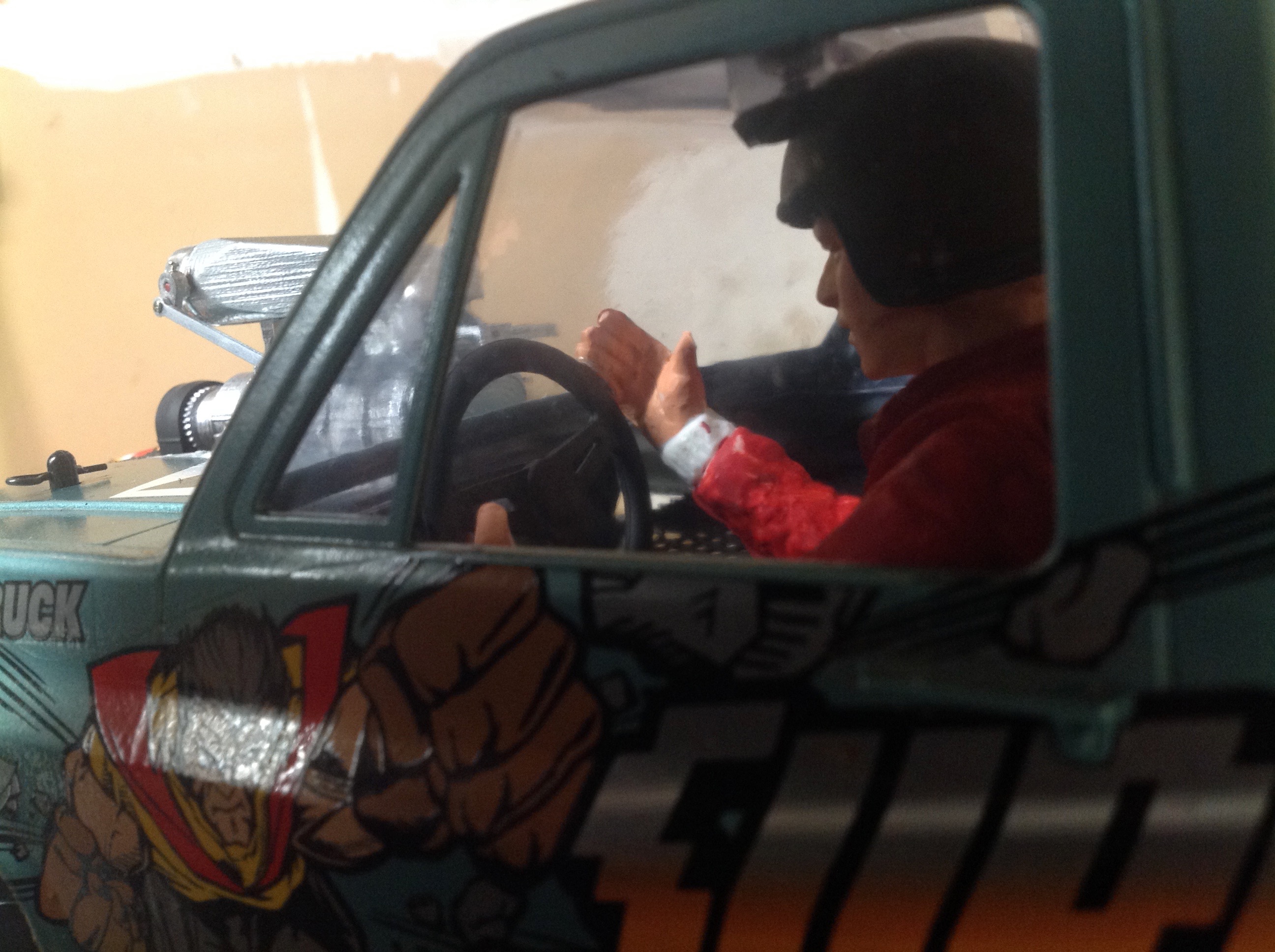
Next up is the driver. I used a Tamiya 1/10 scale figure. He
seems a little large for this model, but it was as close as I could
get. I had to saw off his legs to get him to fit while still
keeping room for the electronics beneath. I chose the head with
the helmet since that seemed appropriate for a monster truck.
Behind him I put a pair of bucket seat backs.
A couple of final shots of the driver.
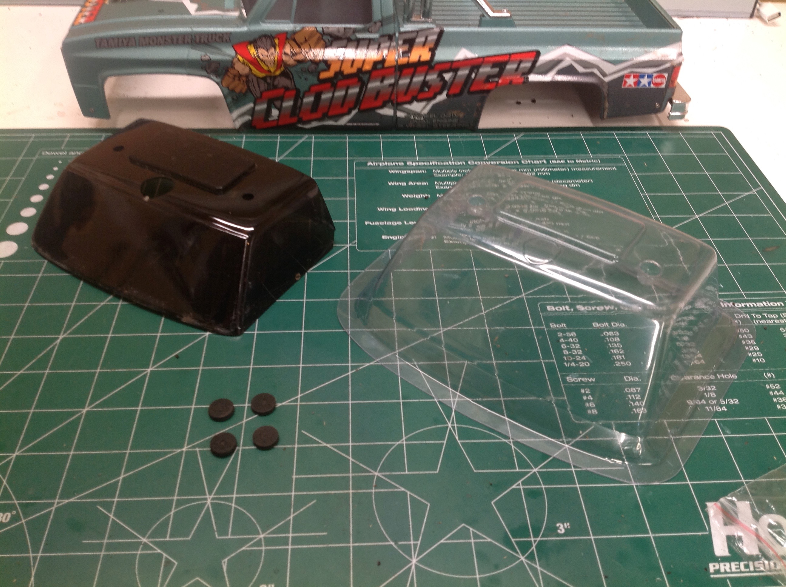
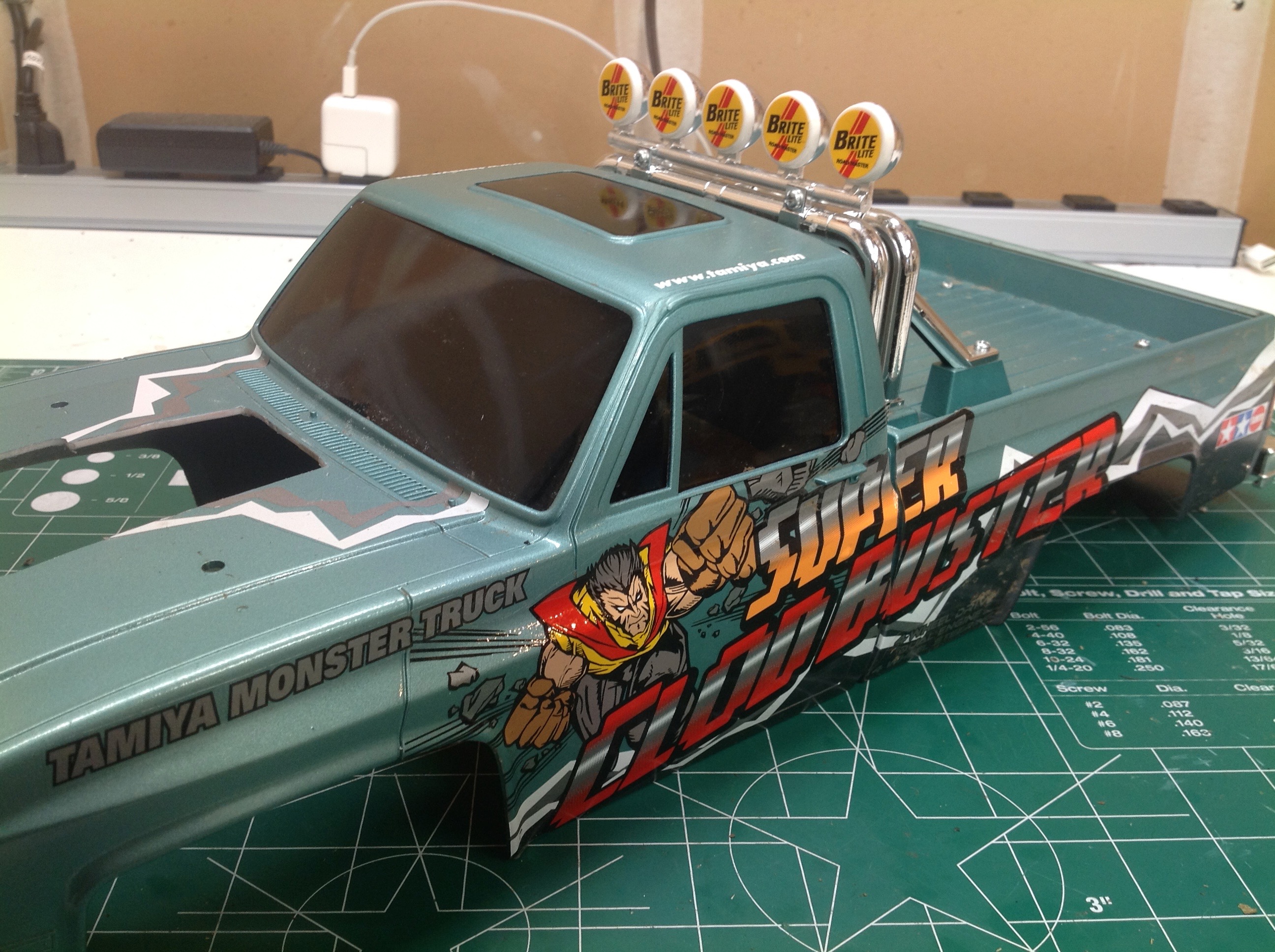
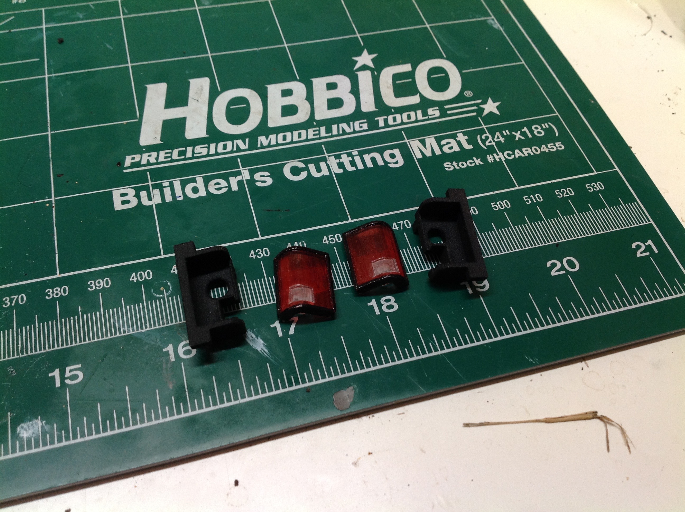
The last thing to do is improve the lighting. I got these tail
light lenses and housings 3D printed from AMPro Engineering and then
painted the lenses as shown.
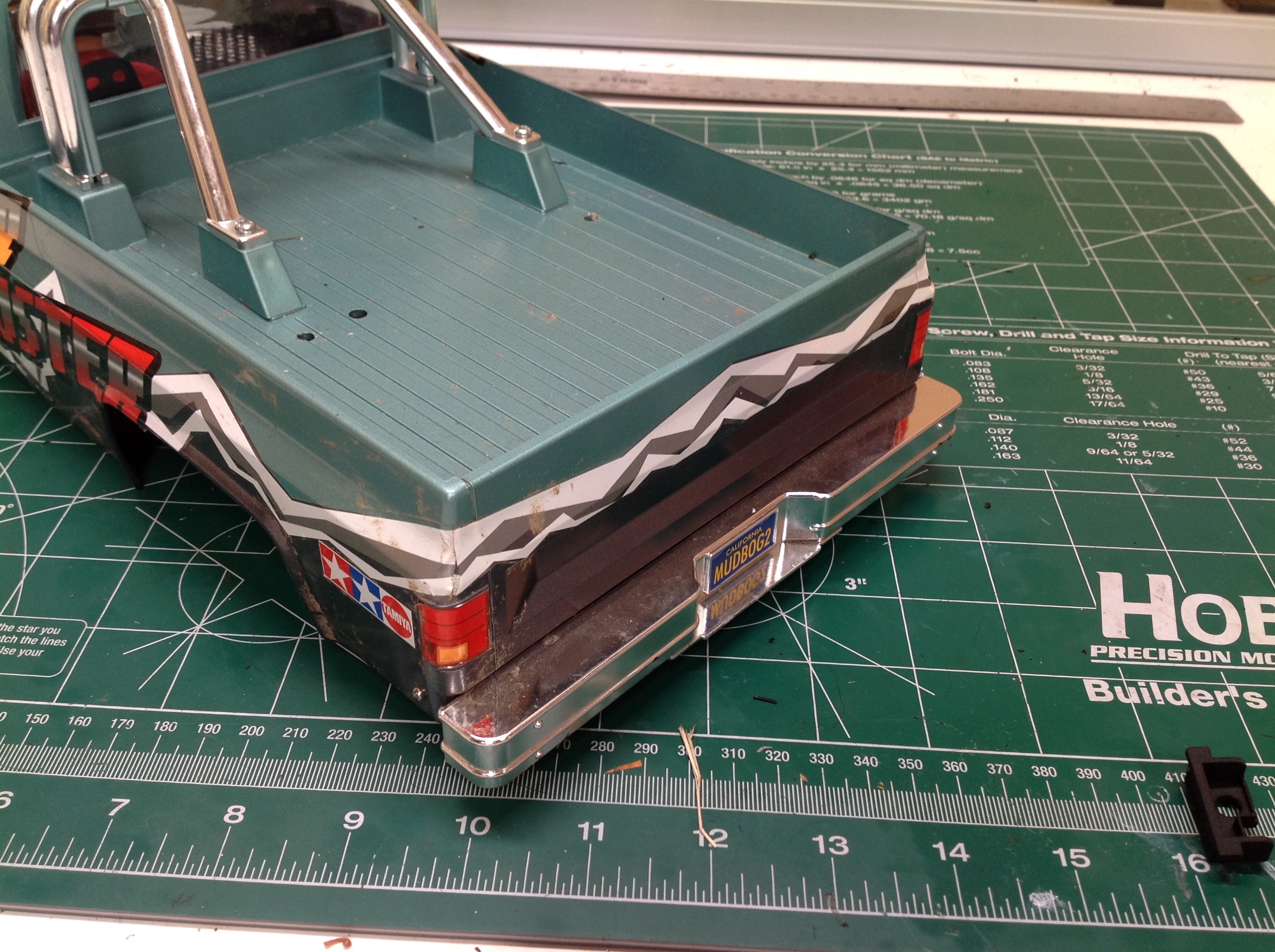
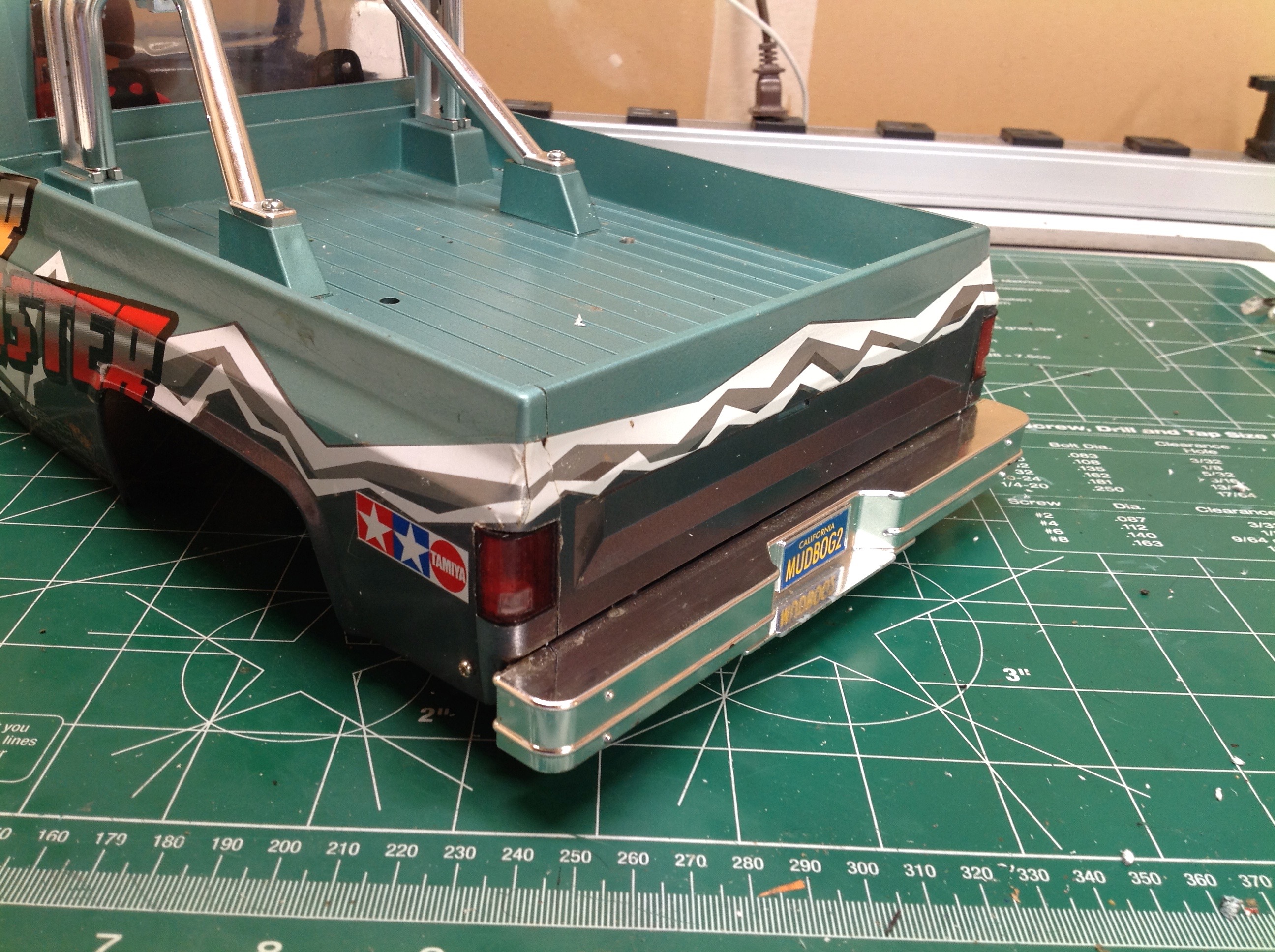
Here is the rear end before and after. The stock tail lights are
just stickers. I used a drill, a Dremel, and a file to hollow out a
spot for the lenses and then glued them in. There are red LEDs in
back and halogen LEDs up front controlled by a Tamiya light box.
Phase 4:
Another summer arrived and I found that I wasn't really driving my Clod
because the steering was so bad. I finally decided to cave in and
go to dual axle mounted servos instead of the single standard chassis
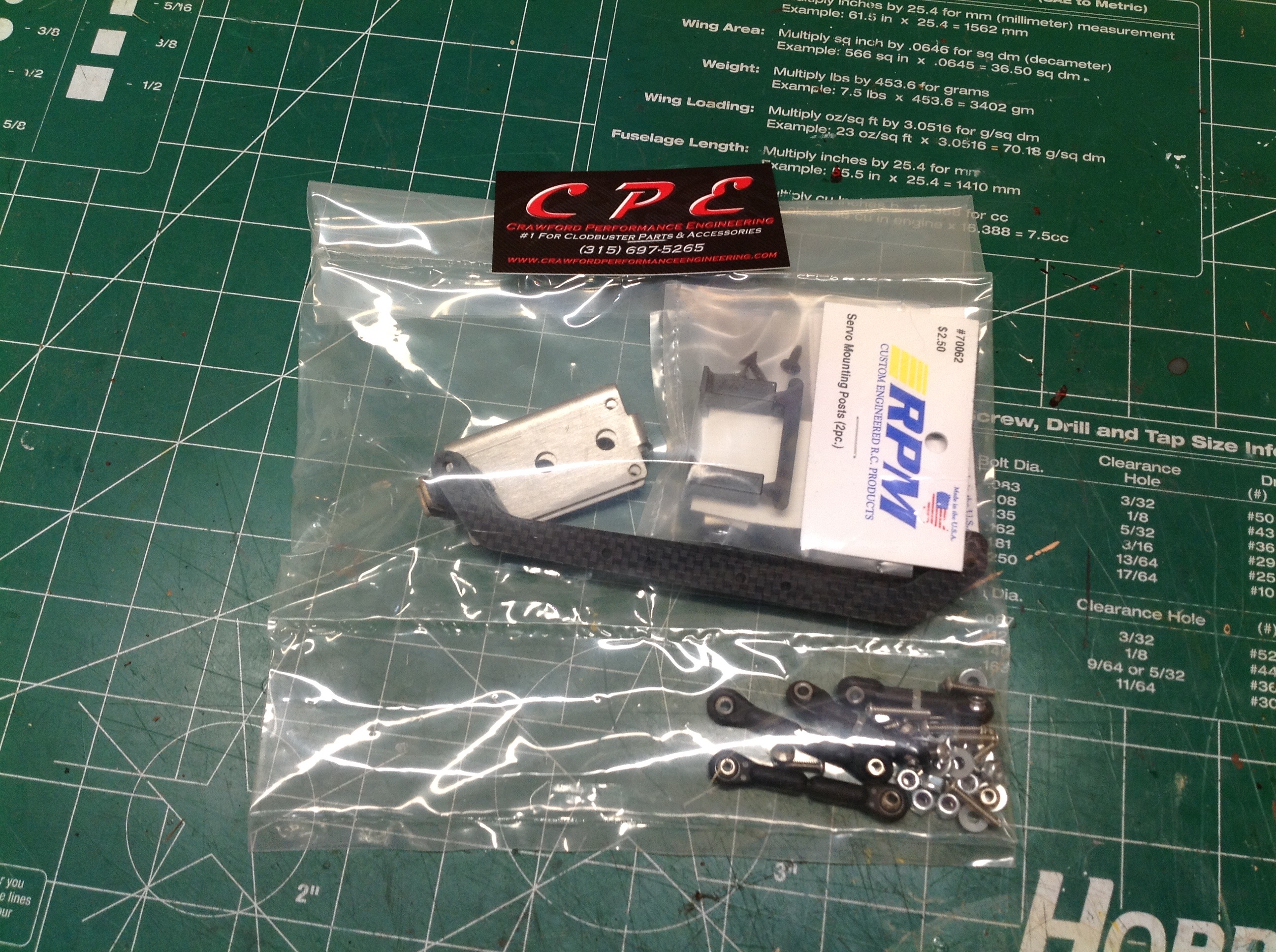
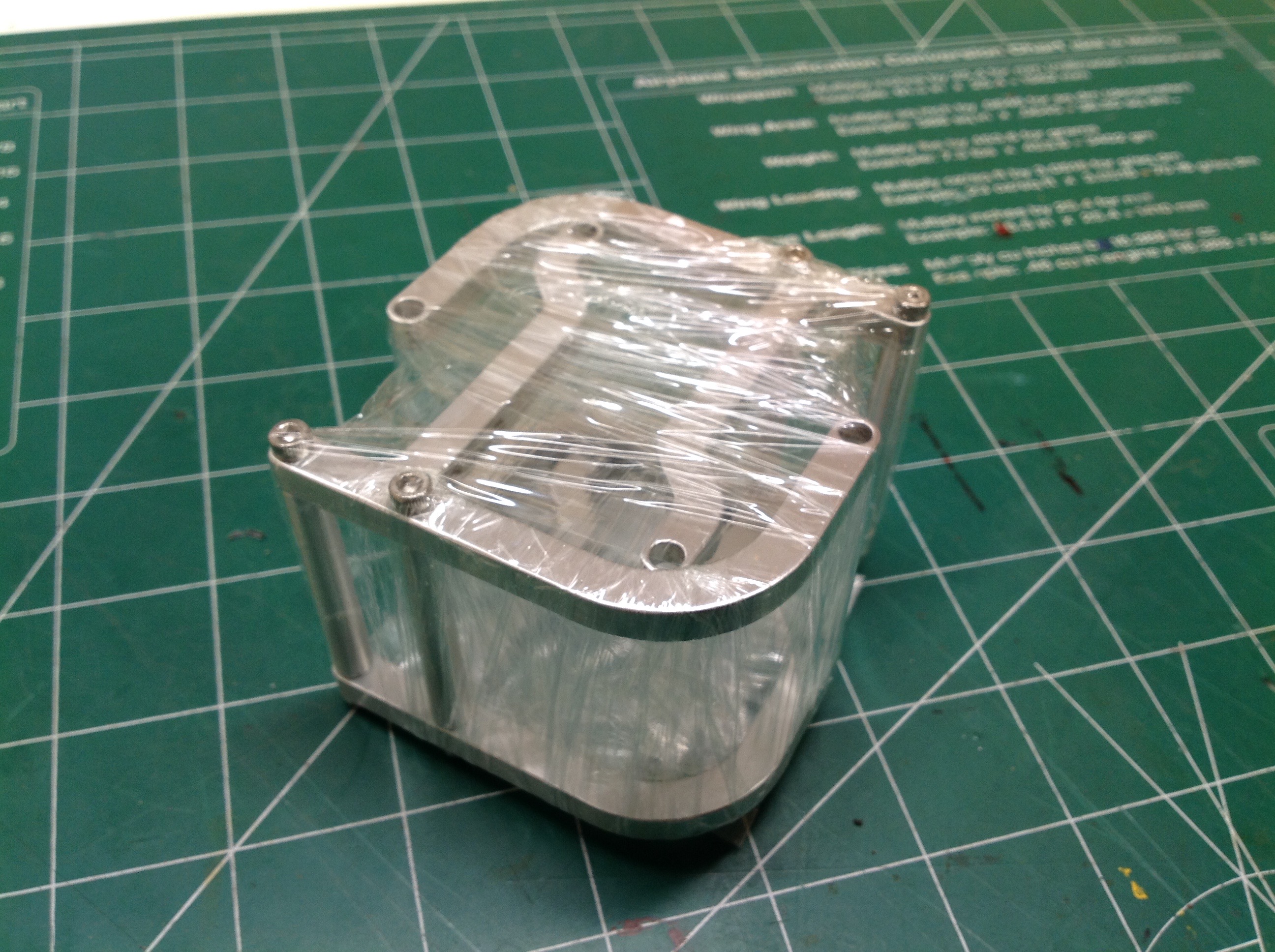
mounted servo. I started by ordering the nice BTA (Behind the
Axle) servo mount and link set from CPE shown on the left , but it
didn't
work. The servo mount interferes with the shock mounts so it
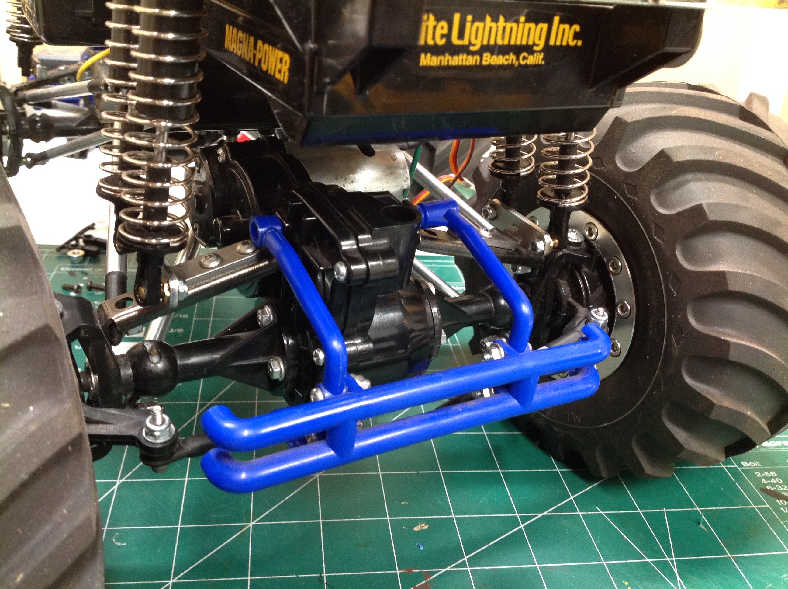
can't be used. Instead I found a set of aluminum front bumpers
with an integrated servo mount on eBay.
Here are some pictures of the front axle before and after the
upgrade. The changes are pretty obvious. The original blue
plastic front bumper has been replaced with aluminum and now I have dual
steering servos. It made all the difference in the world.
The Clod now handles like it should and is actually fun to drive.
©2018 Eric Albrecht