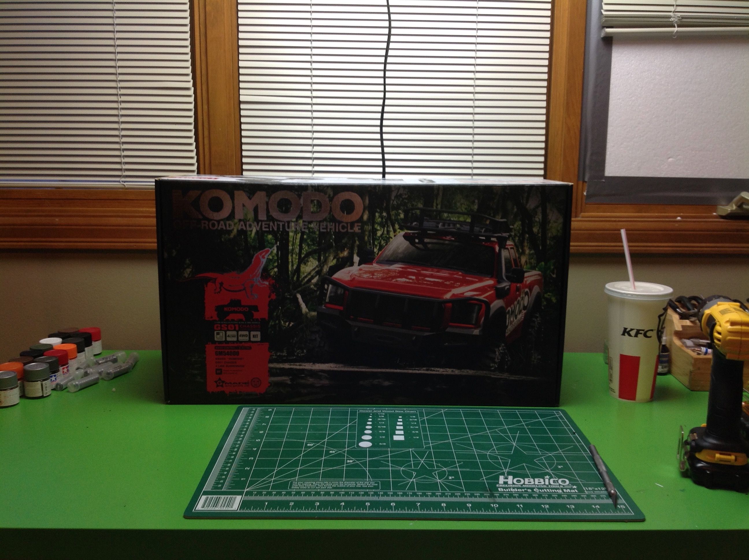
The Komodo is not that easy to find in the USA. I
have never seen them at a local store, but I managed to find one
domestically on the Internet. The box is nicely colored and looks
like quality. At this point I really had no idea what to expect given my total lack of familiarity with the company.
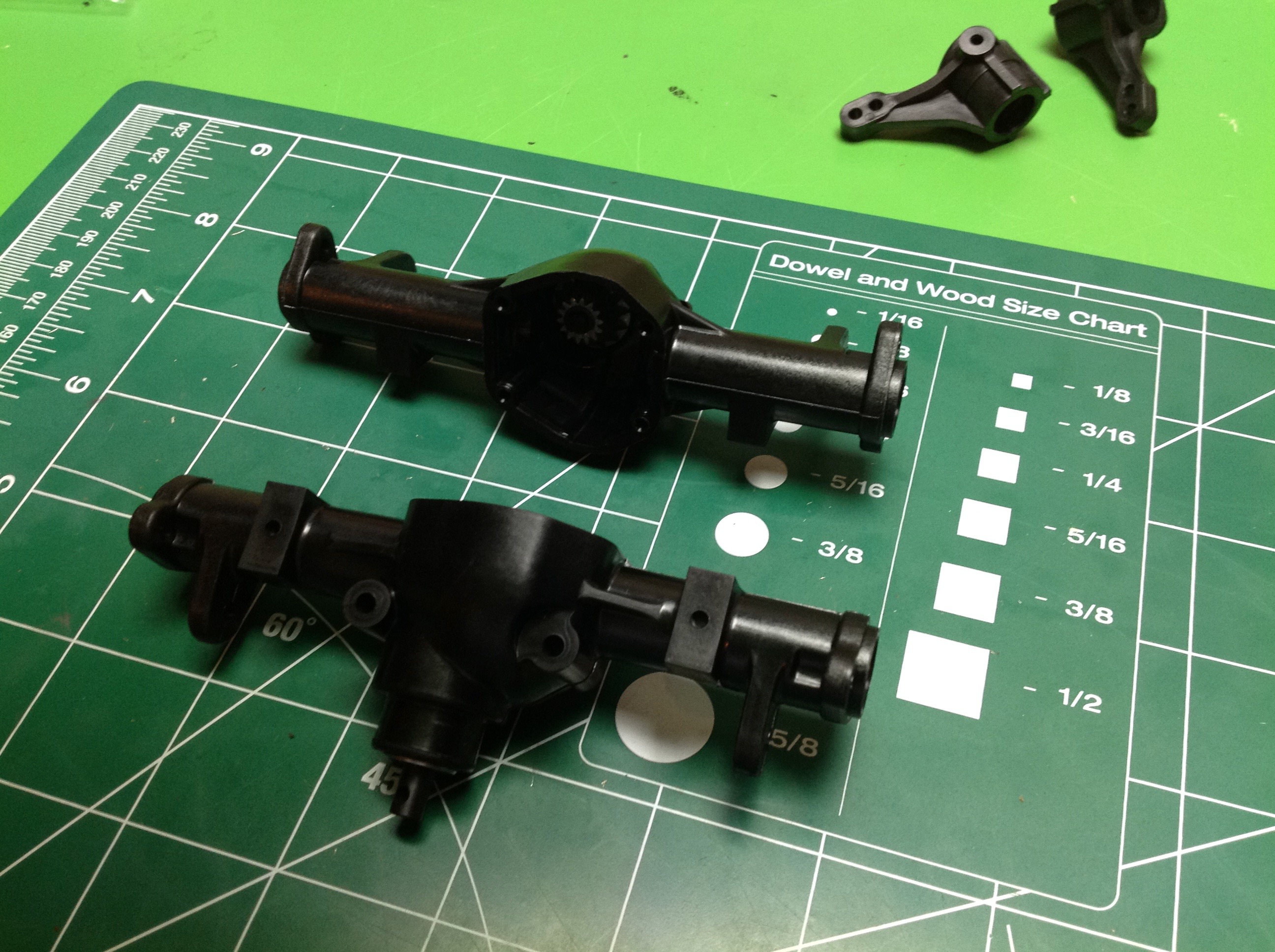
First thing to do is push the included ball bearings
into the axle housings along with the differential pinion gear.
The diff gears appear to be cast metal, the axle housings plastic.
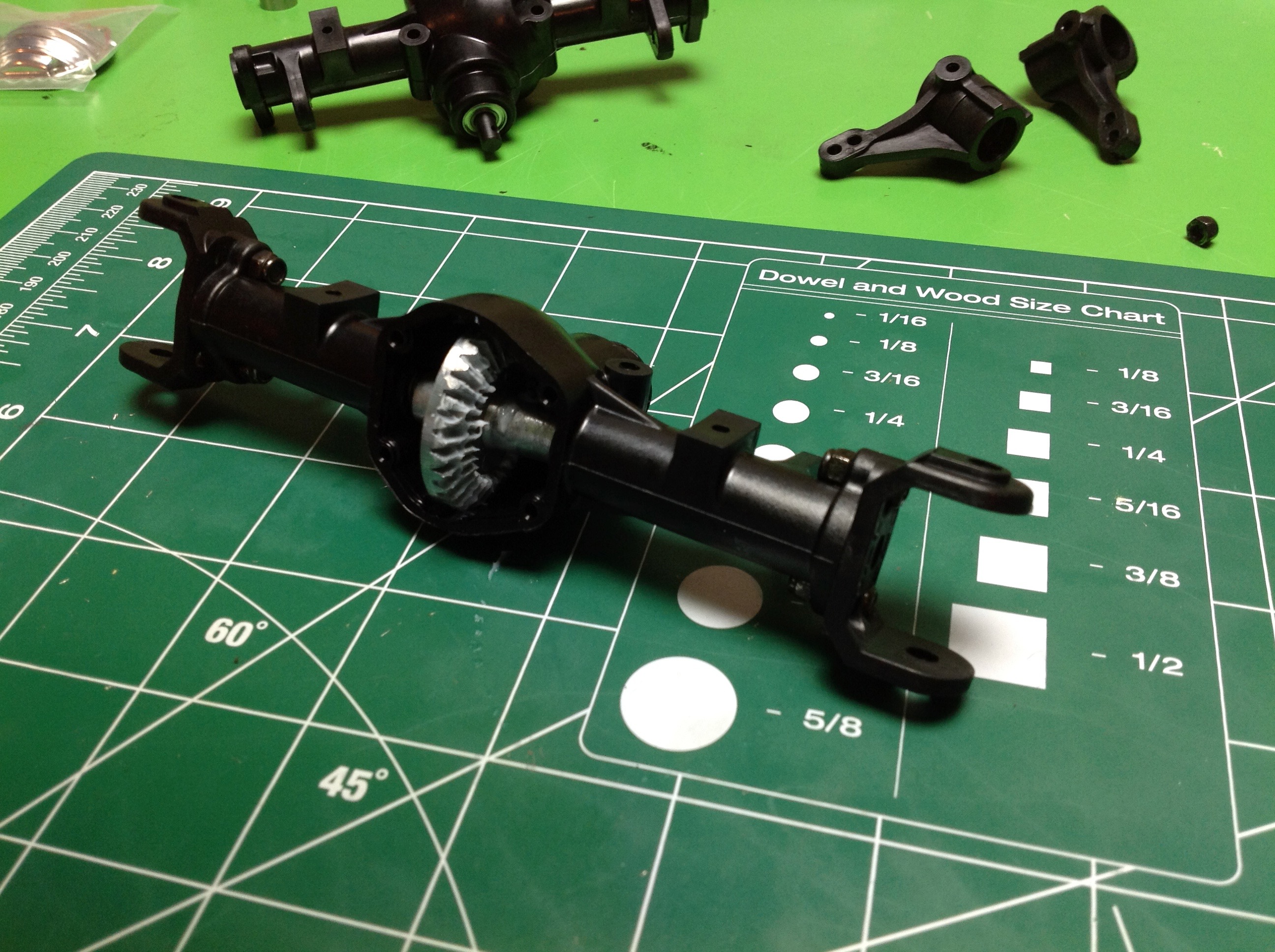
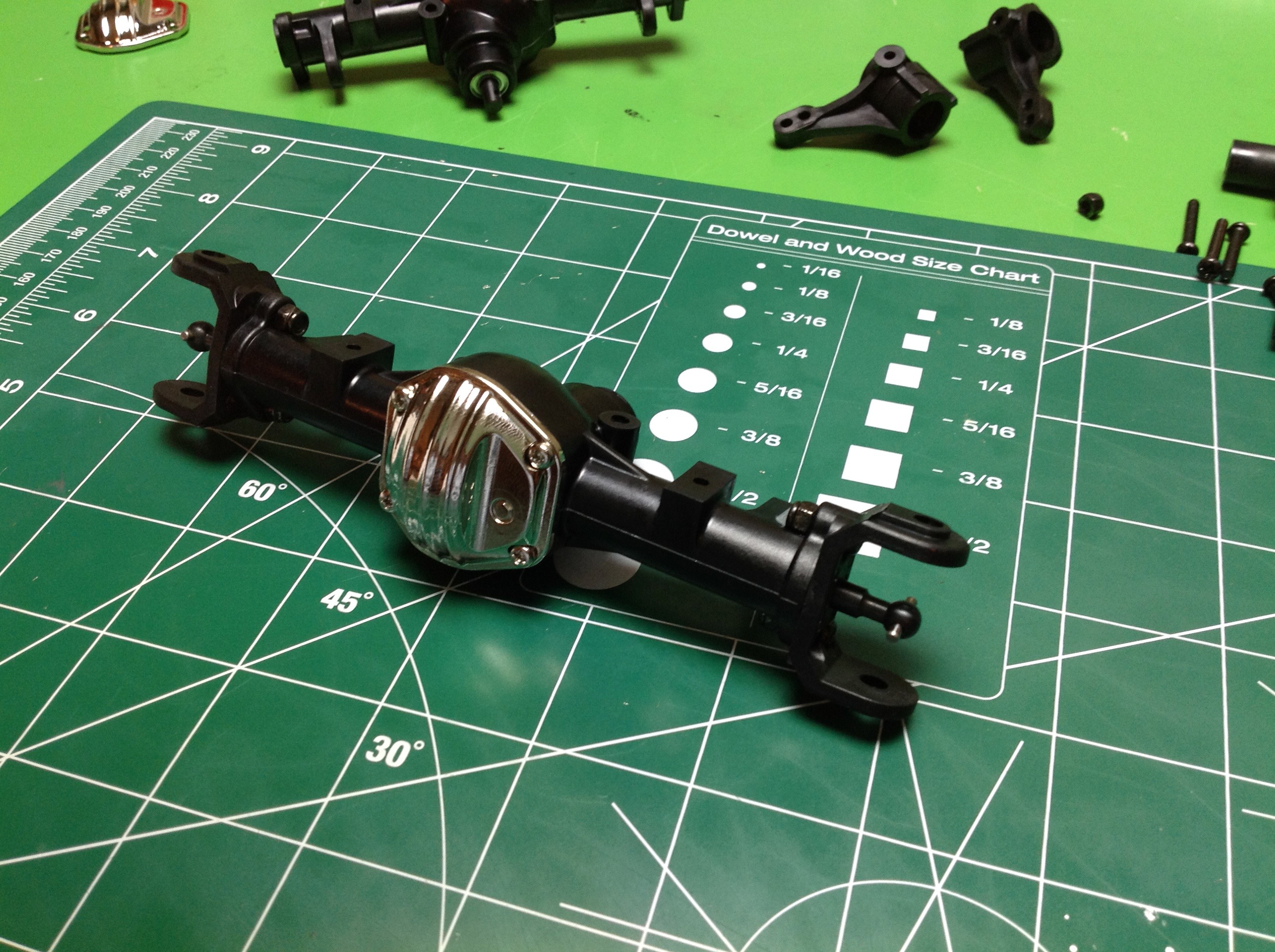
Next you drop in the ring gear for the solid
differential. The diff cover is nice plated metal and the axle
dogbones seem to be steel. So far the quality is quite good.
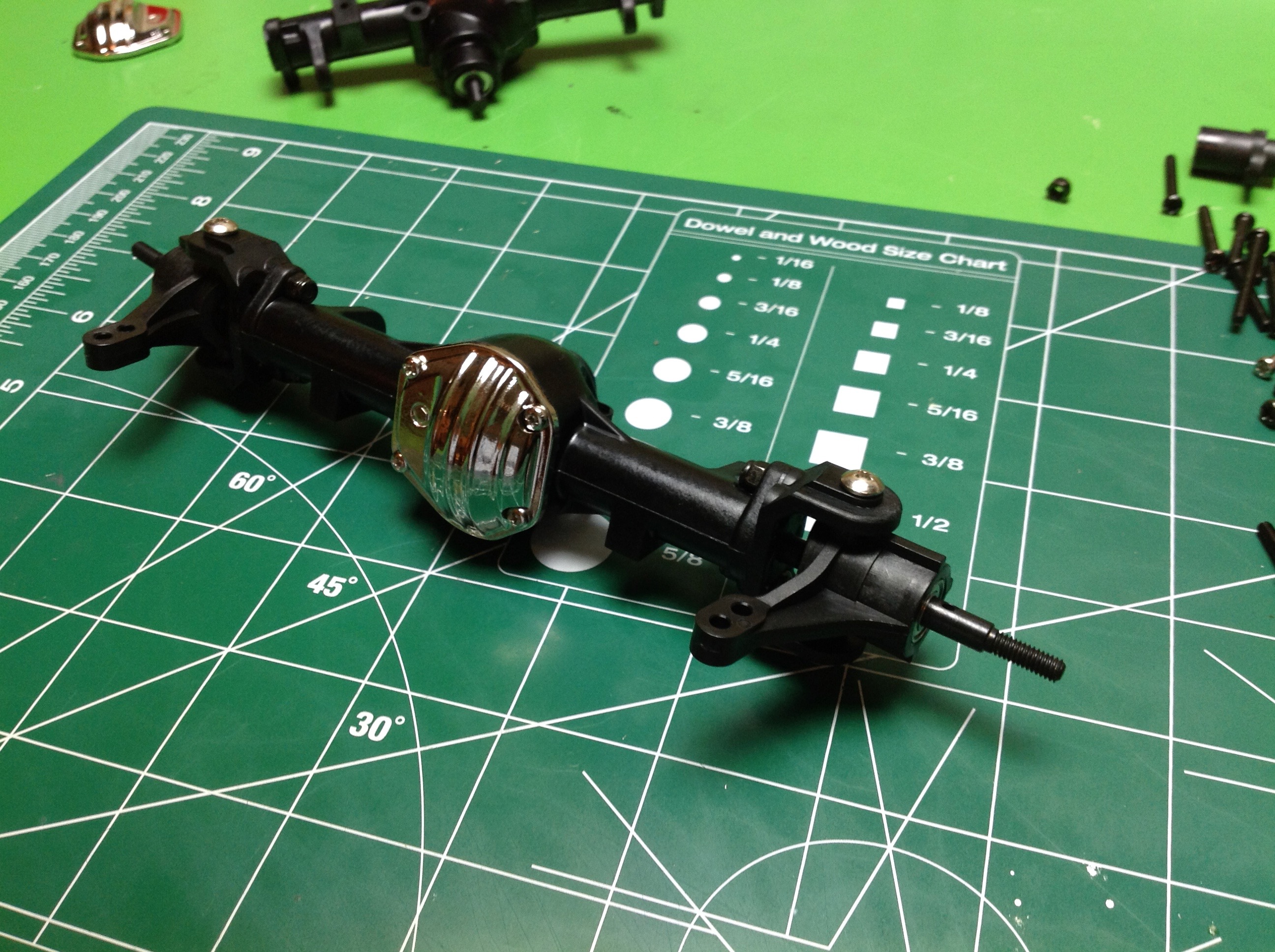
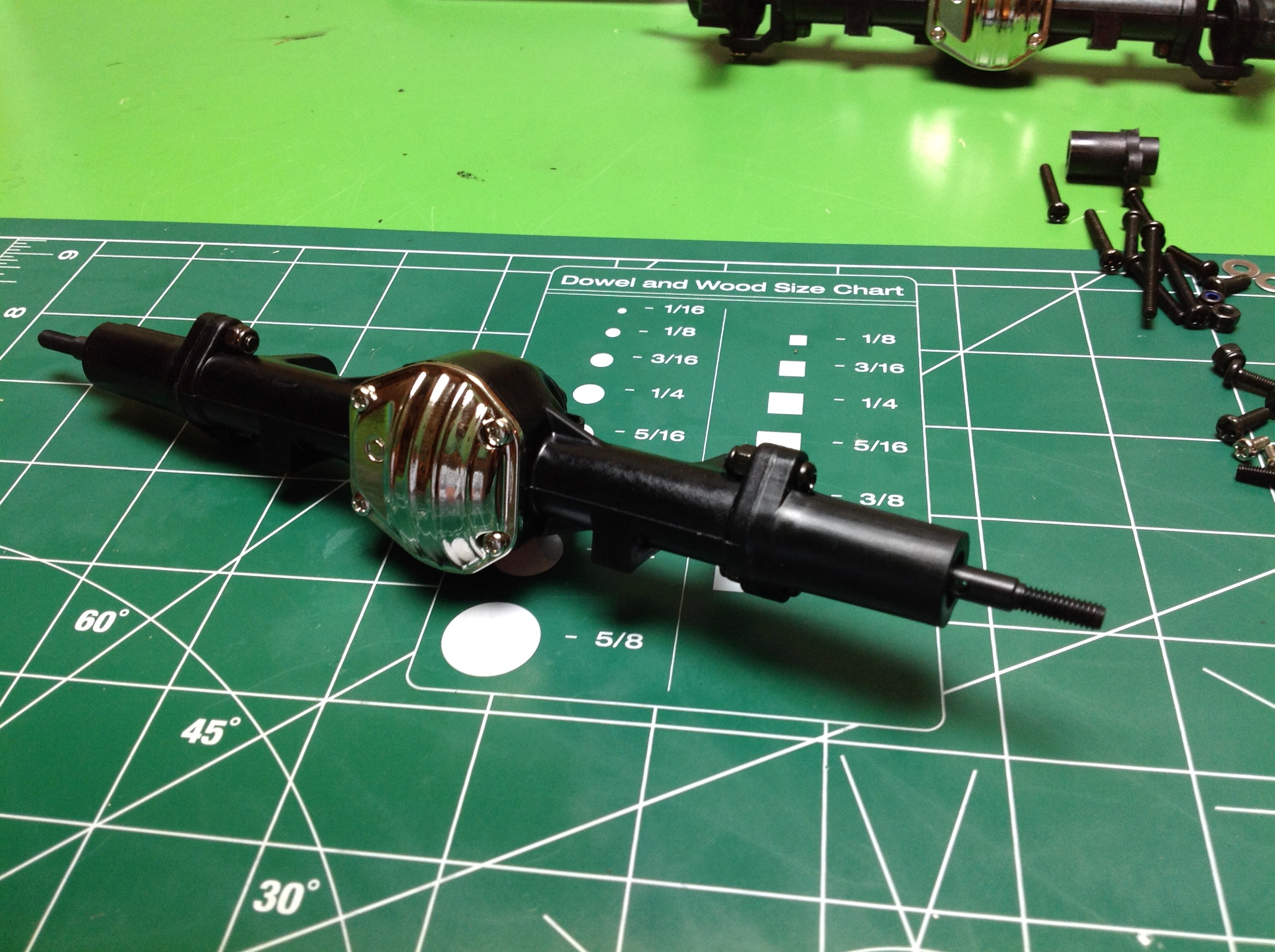
The front and rear axles use the same center section
but then have different ends bolted on. The front end gets a pair
of C-hubs for the steering knuckles and the rear end gets straight axle
caps. In both cases, the screws that attach the ends do not thread
into the plastic but have a nut of the far side. This is good for
strength but a big pain for assembly because there is no way to get a
standard hex wrench around the nut with no clearance. You need to
use an open end wrench or a needle nose pliers. The left and right
C-hubs need to be installed in a particular orientation to accommodate
the kingpin inclination. This is a good place to mention that
Gmade instructions do not use part numbers. There is a number for
the tree that the part is on, but no number for the part itself.
This means when parts look similar you just have to figure it out.
Not great for beginners.
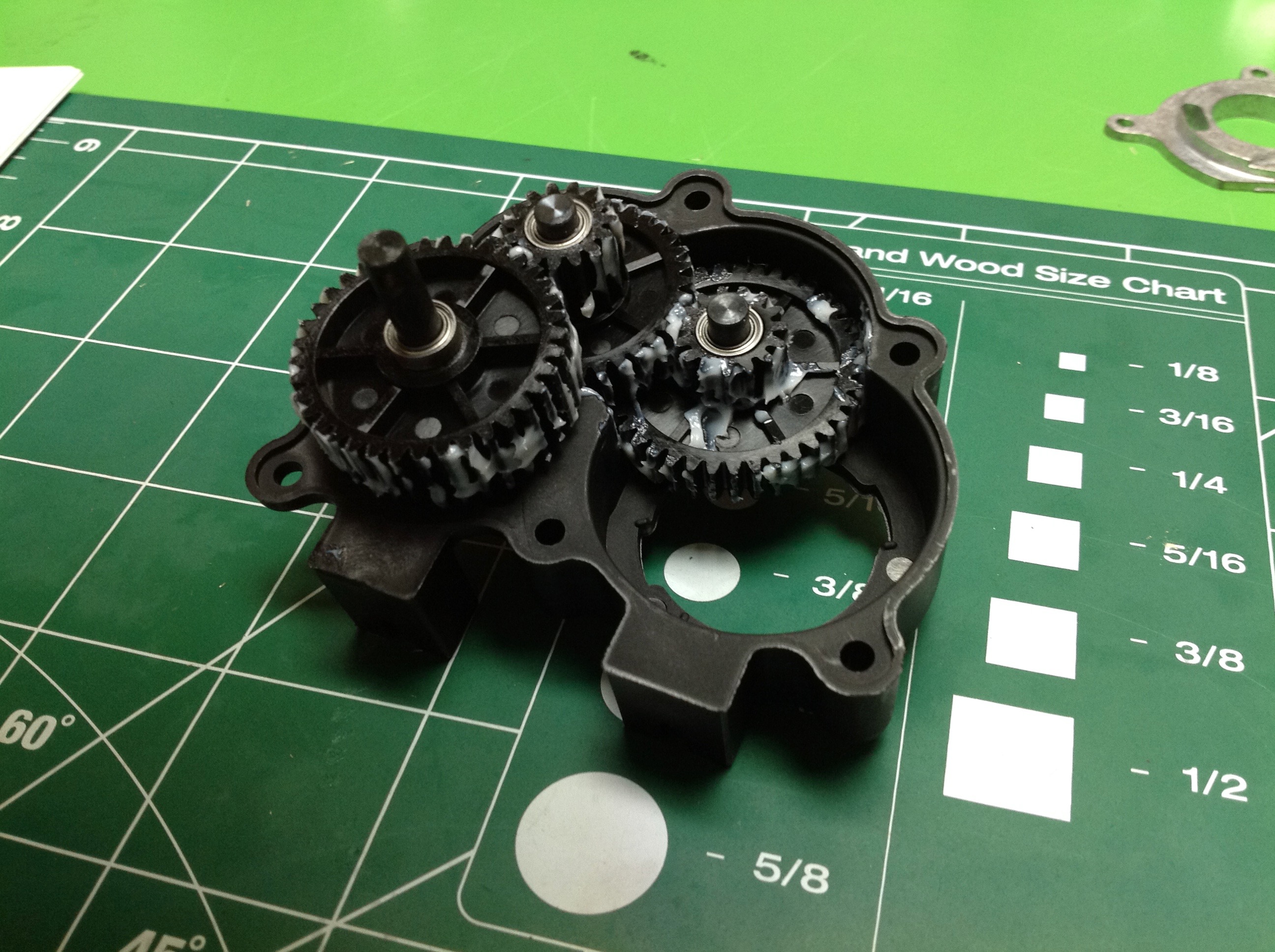
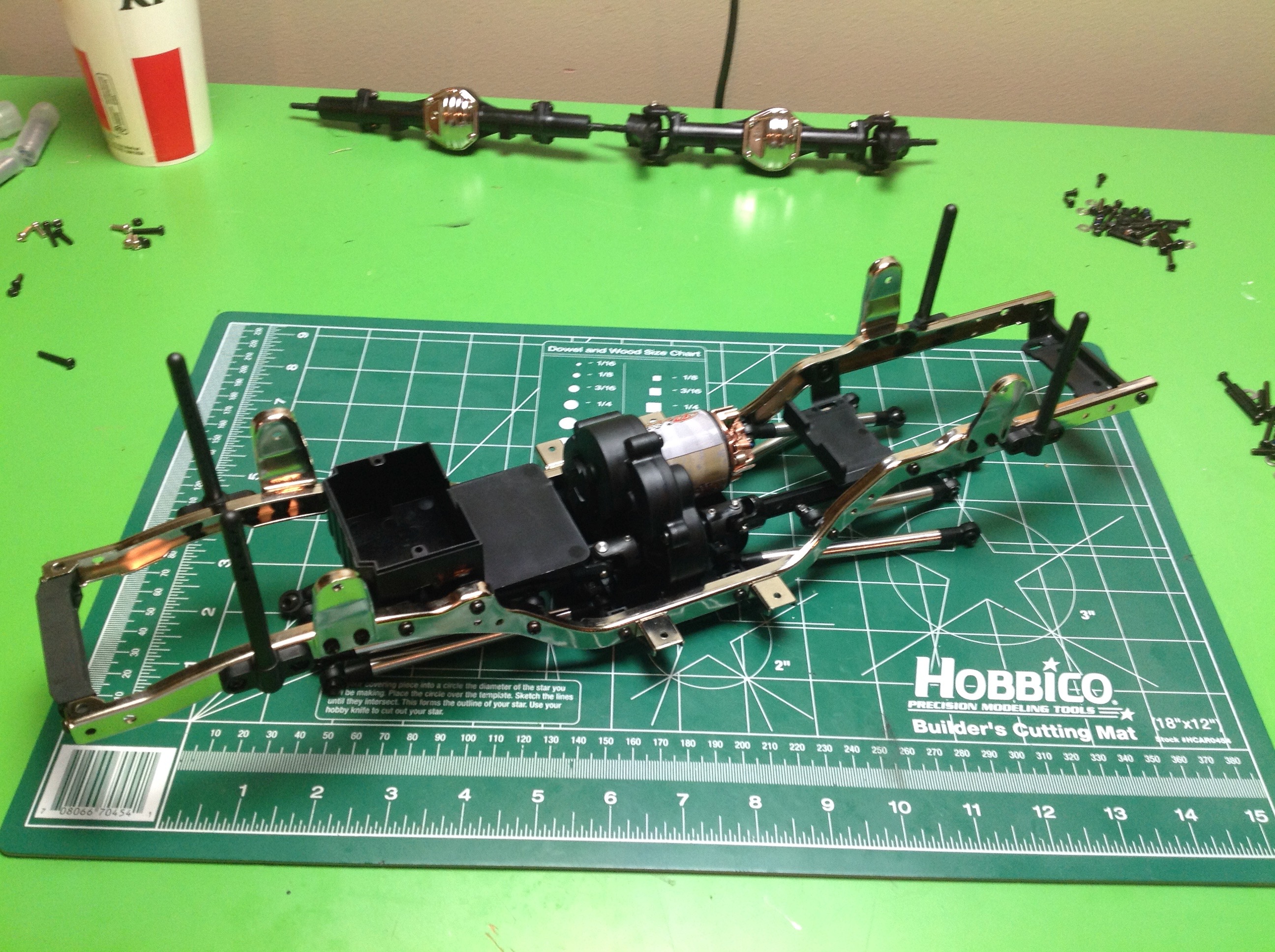
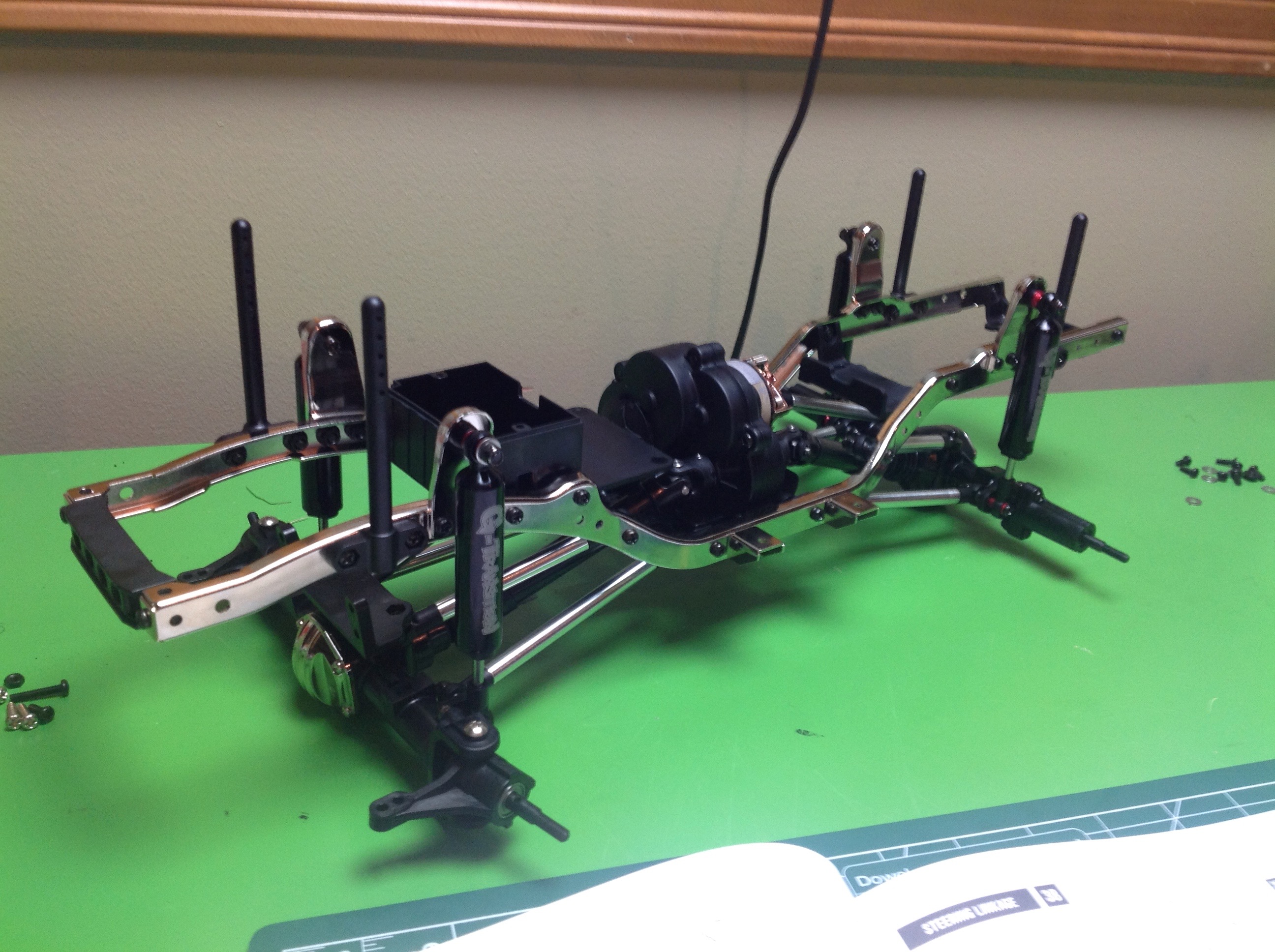
Next comes the transmission with its large plastic
gears. Make sure to apply plenty of grease here. I found
that the gears did not turn smoothly so I took the gearbox apart a
couple of times to try to fix it, but apparently the gears are just not
that finely made. They made a lot of noise for a long time until
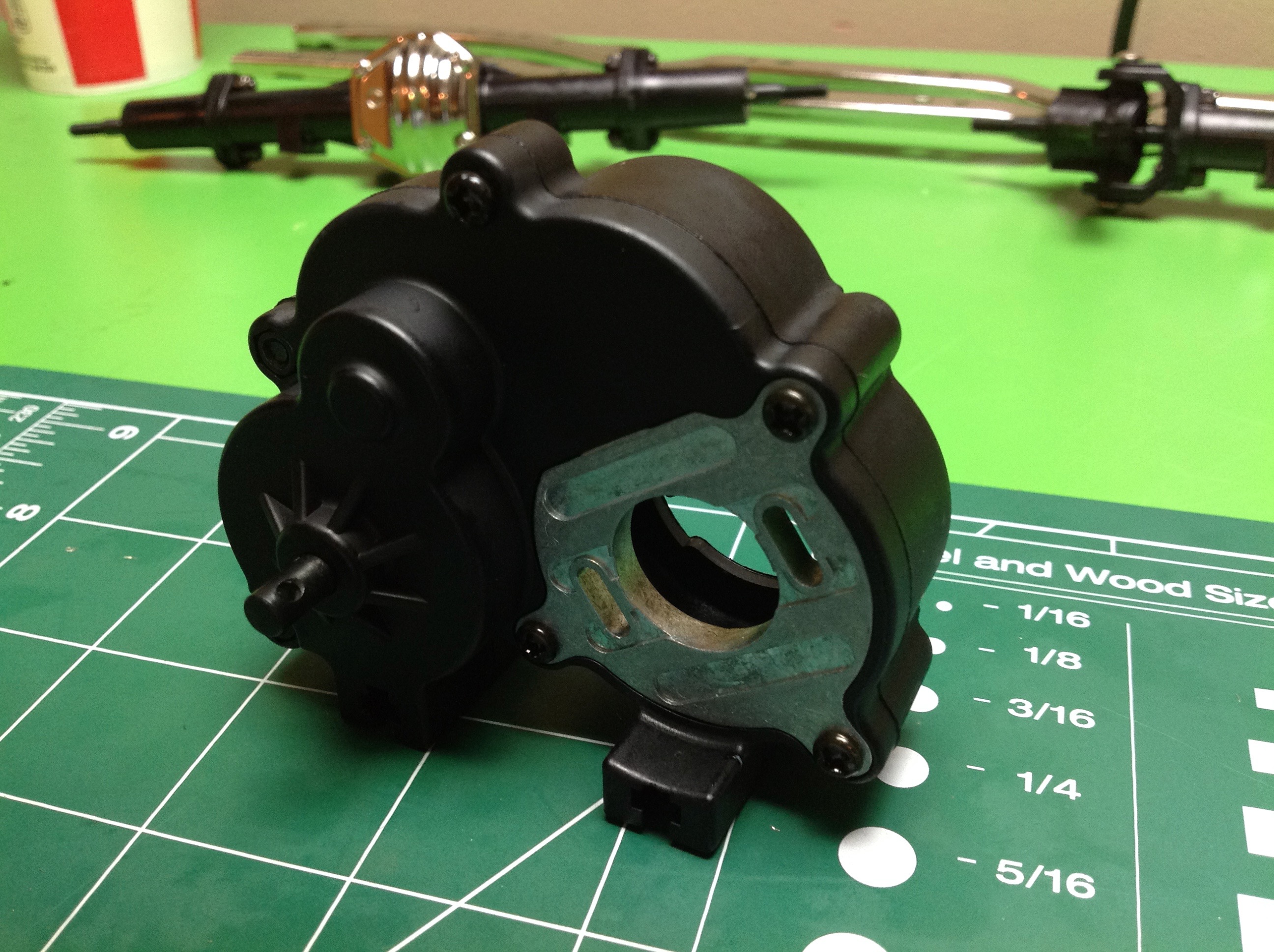
they wore in. In the second photo you can see the metal motor
mount.
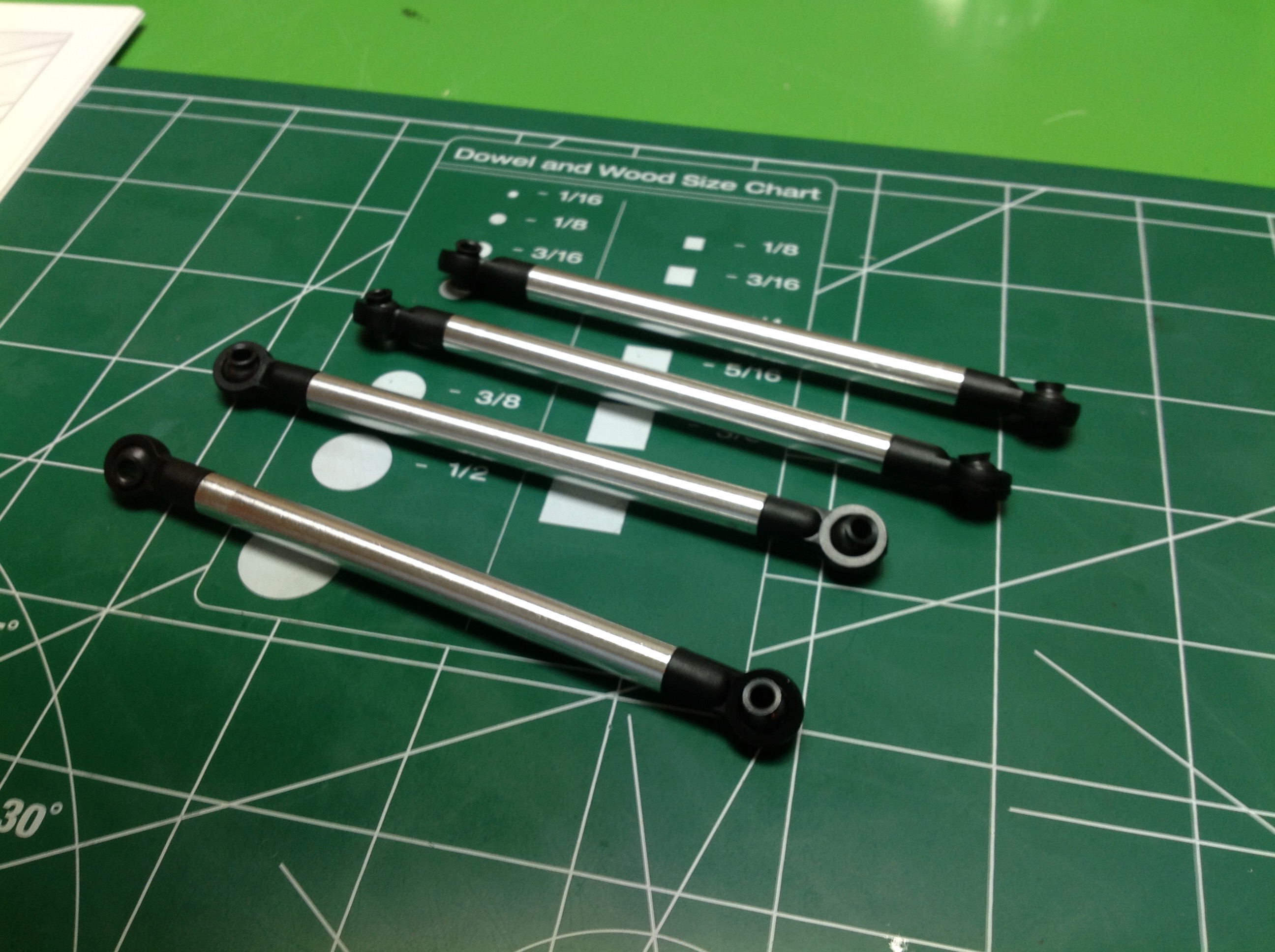
The kit uses very nice aluminum links with plastic rod
ends and steel balls. All four are the same length so you can't
screw it up.
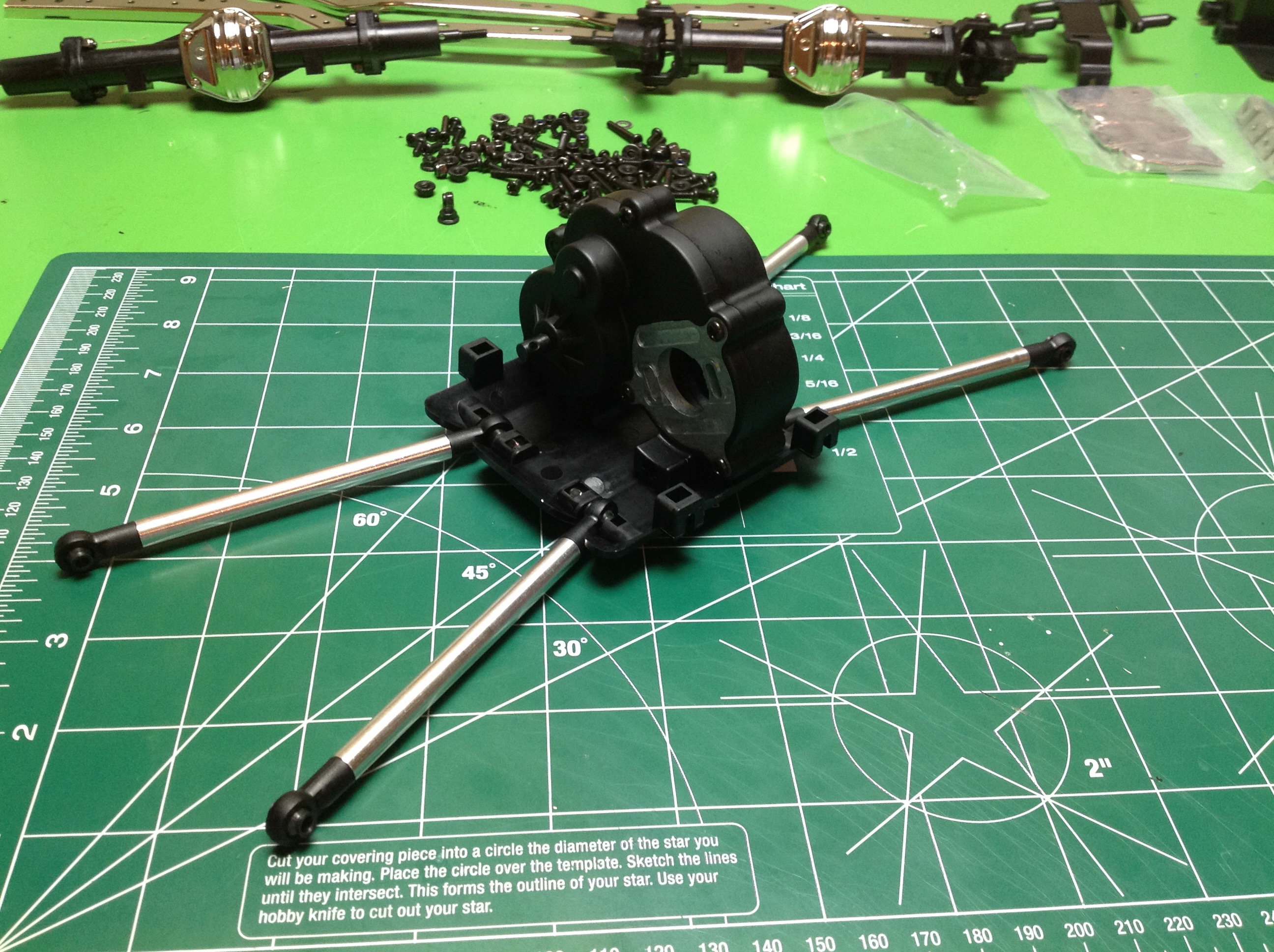
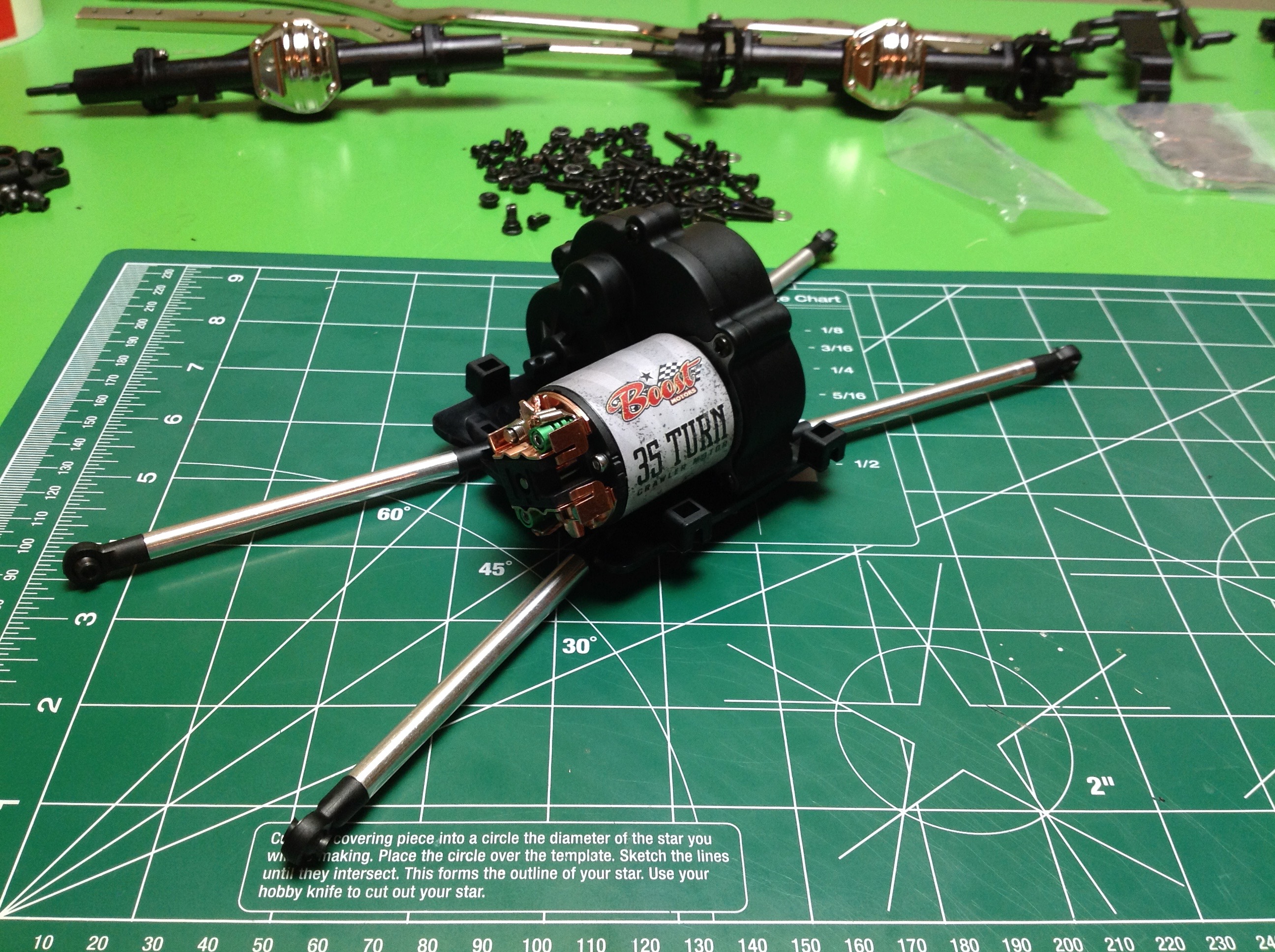
The gearbox gets attached to a slider plate which also
houses the inner ends of the links. I installed a 35 turn brushed
motor from RC4WD and the kit supplied pinion.
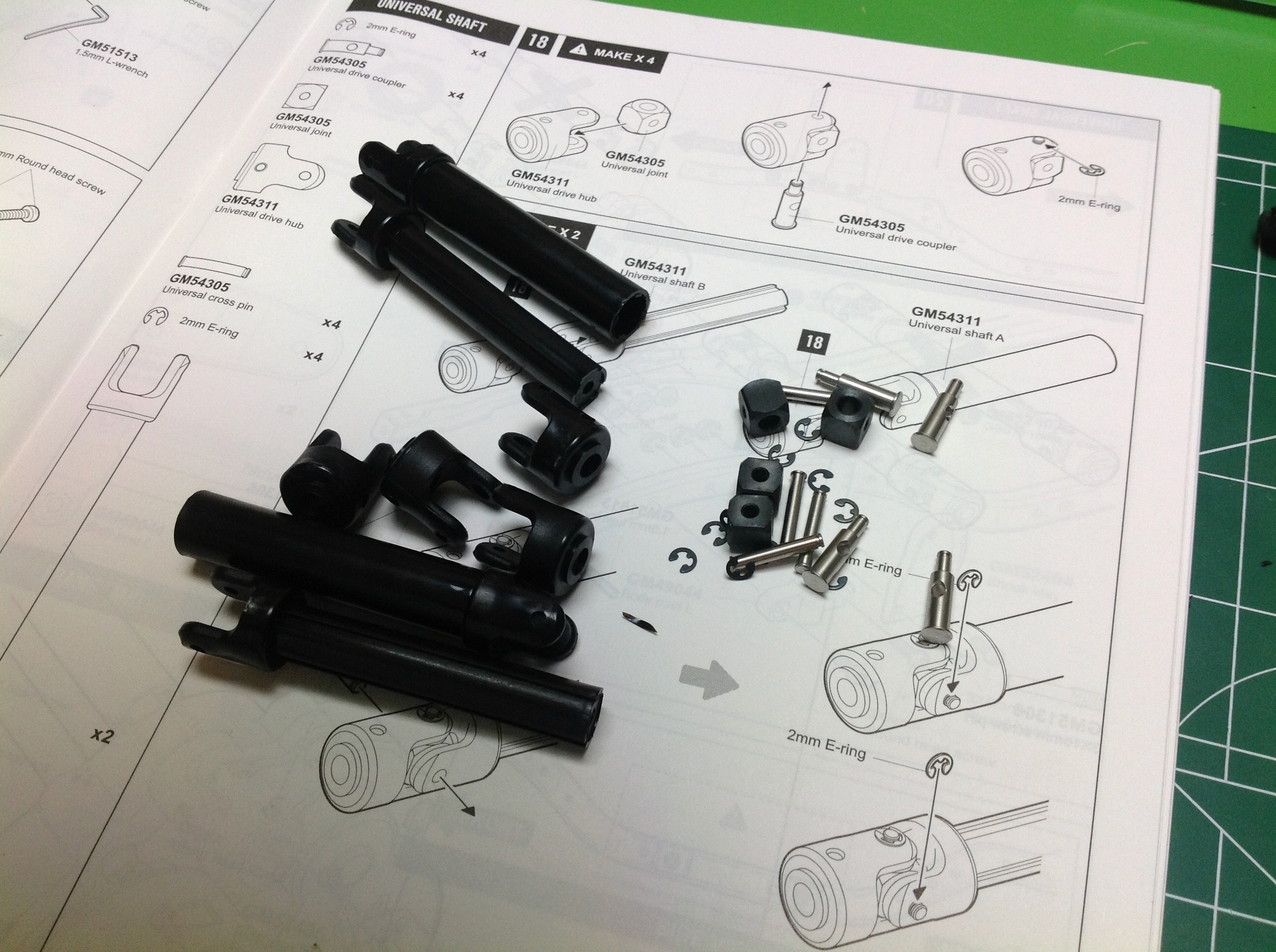
The universal joints need to be built up from scratch
which was a new one for me, but kind of fun. The cross bars are
retained with E-clips. The shafts use a telescoping configuration
with keyed (rather than splined) connections.
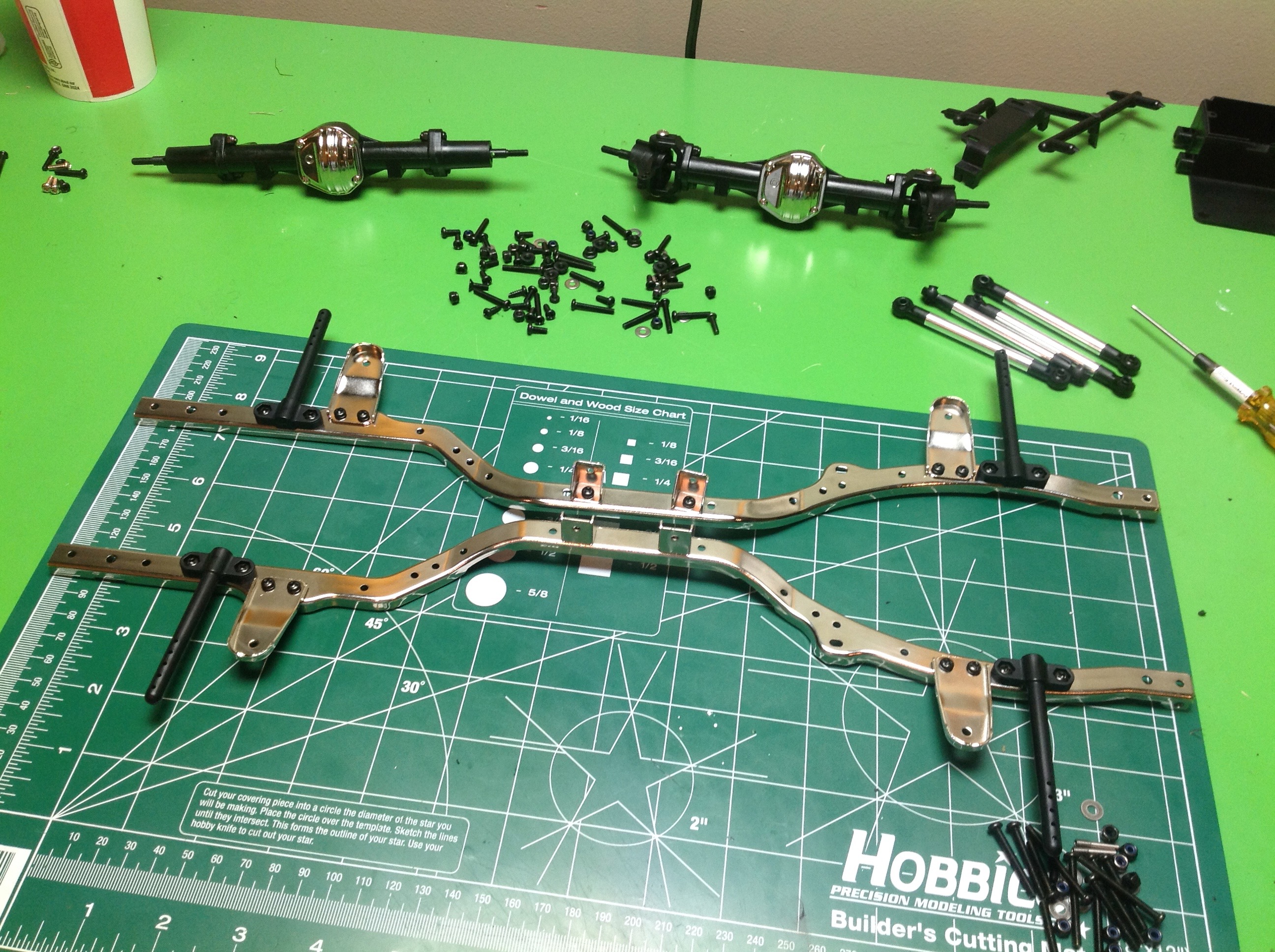
The metal chassis rails are a lovely polished nickel
finish which I really like but is probably not scale accurate.
Onto this attach the body posts, shock mounts, and side brackets.
Three cross members, the transmission, and a radio box tie the rails
together. 4 more links are built which attach directly to the chassis rails.
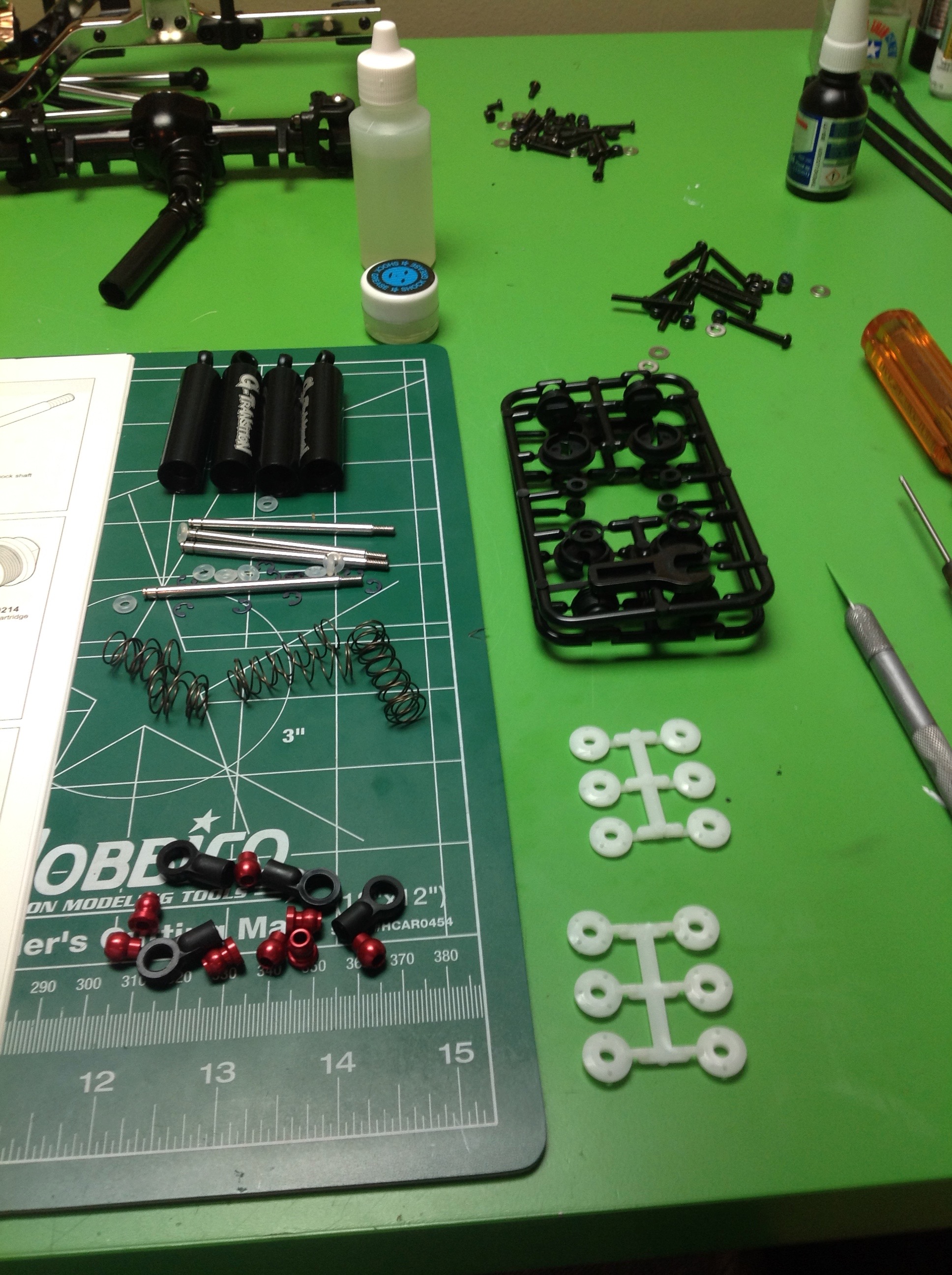
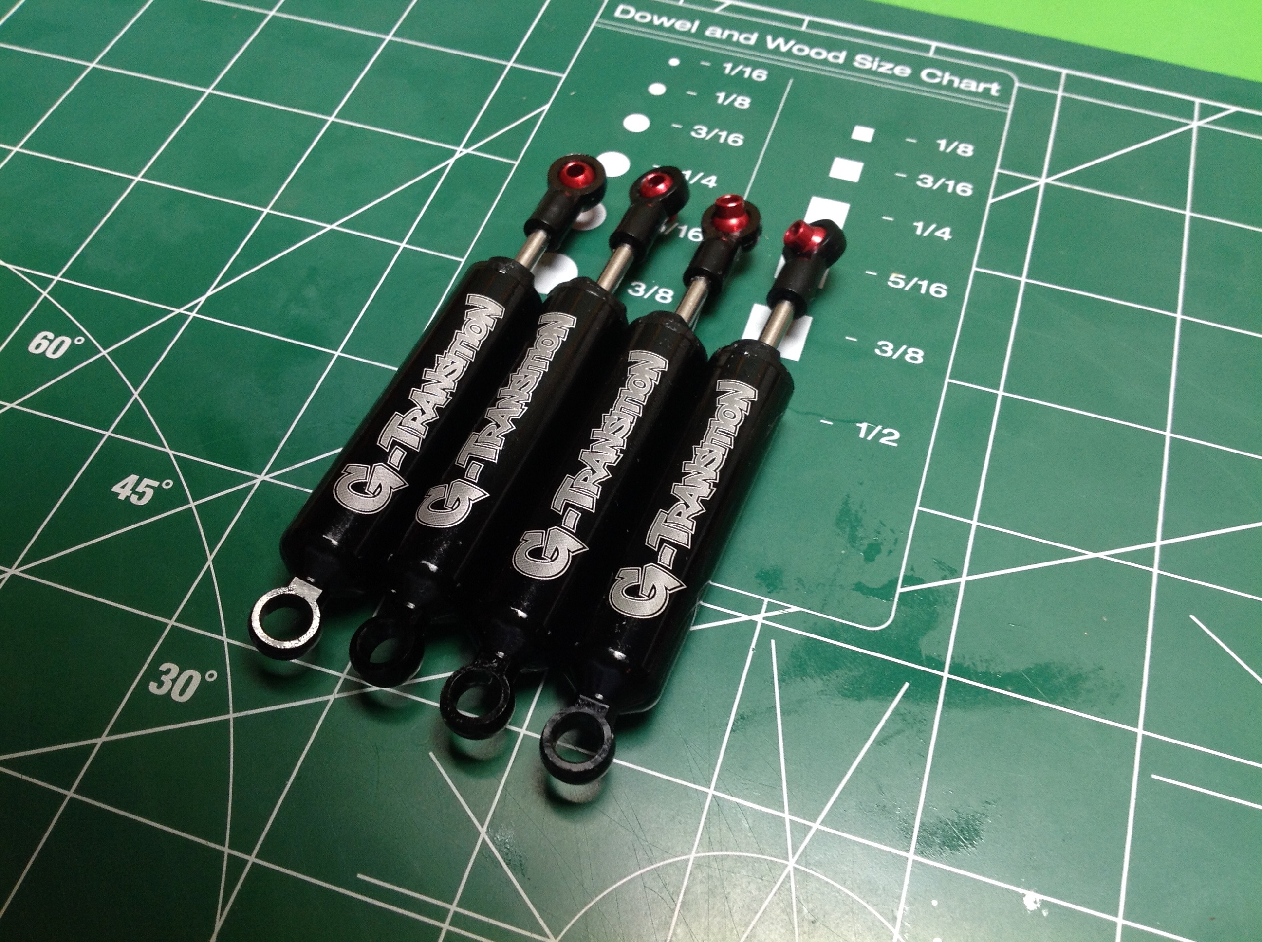
Time to build the shocks. I've built a lot of
shocks, and these are fairly unusual for a couple of reasons.
Firstly, the springs are internal so there is no typical coil-over
appearance. Second, there are two springs inside each shock, one
on either side of the piston. The result of this is that the
unloaded state of the shock is an interim length, not a fully extended
length. I initially found this odd, but I love the way it works
out. This helps drop an wheel down into a hole when you encounter a
low spot, and also ensures a ride height which is not fully jacked
up. There is not a lot of fluid volume in these shocks, but
there's plenty of damping for a slow model.
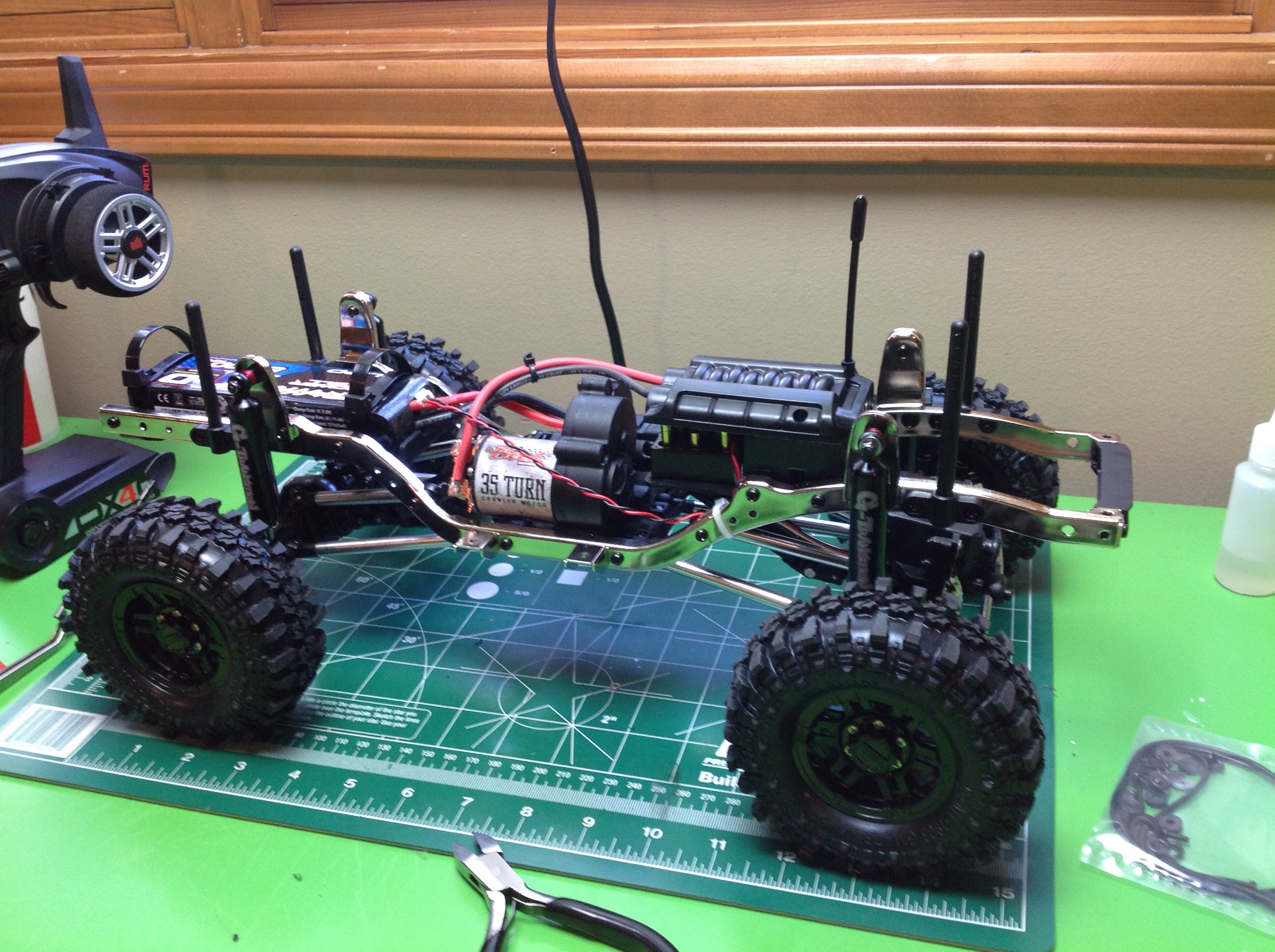
With the shocks installed, we can put the axles on the
chassis. The steering knuckles point forward which means that the
Ackerman angle is backward. Not sure why they chose to do
this. The battery installs in the back with removable zip ties
which I actually like. The radio box looks a bit like an intake
manifold. The disadvantage to this is that the ESC has to fit
under the end of the cover. My tallish Castle Sidewinder was a
very tight fit so I had to bend the wires at a pretty steep angle.
The loose wire you see is to connect the LED control box. The
radio box is not really waterproof since the slot where the wires come
out is open, but it will certainly protect against splashes.
The wheels are plastic bead locks. You'll be tempted to use a power driver on the approximately 1 million screws. I did. Be careful because they strip out easily.
The wheels are plastic bead locks. You'll be tempted to use a power driver on the approximately 1 million screws. I did. Be careful because they strip out easily.