Gmade Buffalo Project
Page 1: Chassis Assembly
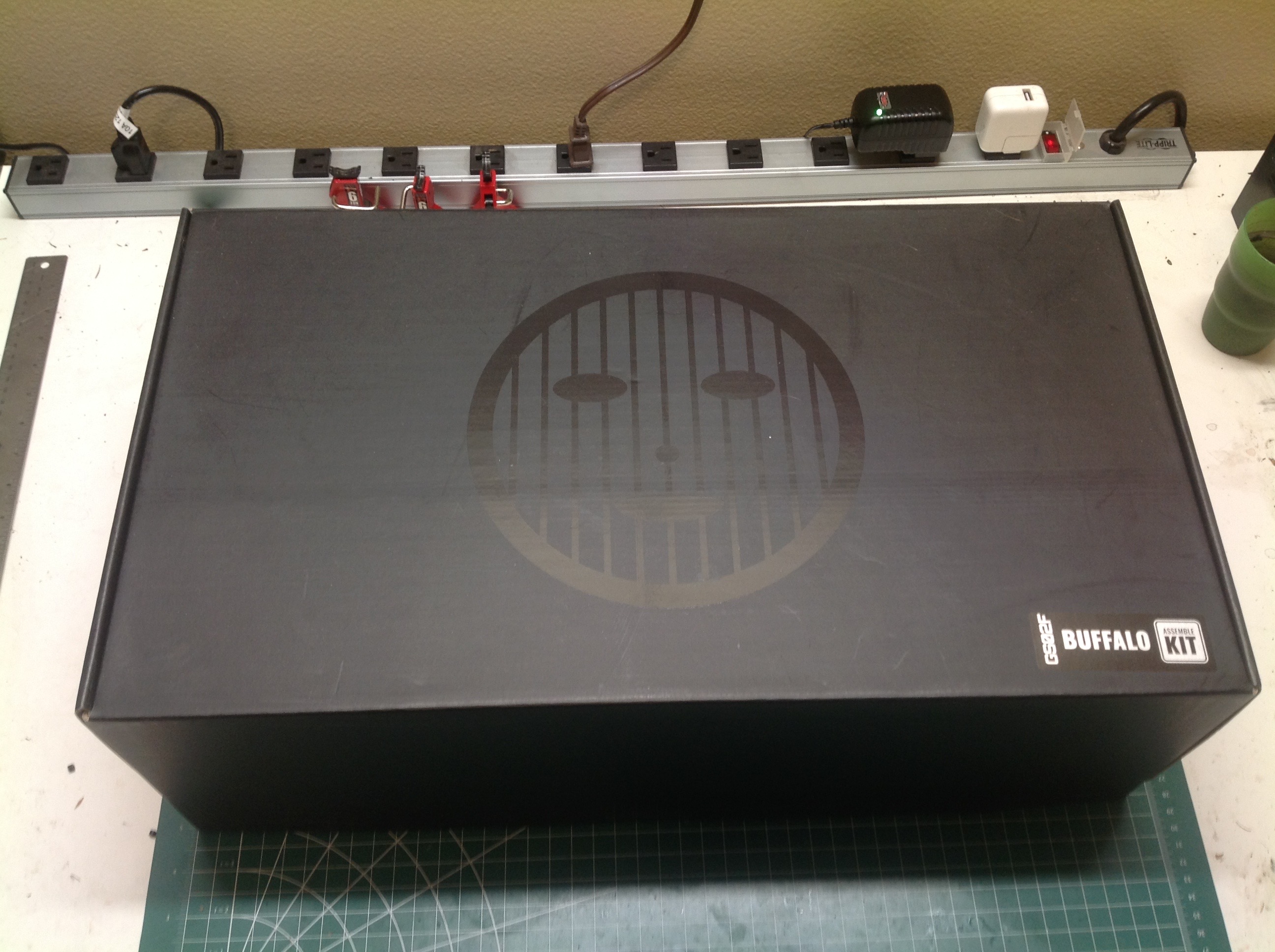
For such a good looking kit, the packaging is very plain. The box
is black with a mildly highlighted black Gmade logo but no pictures of
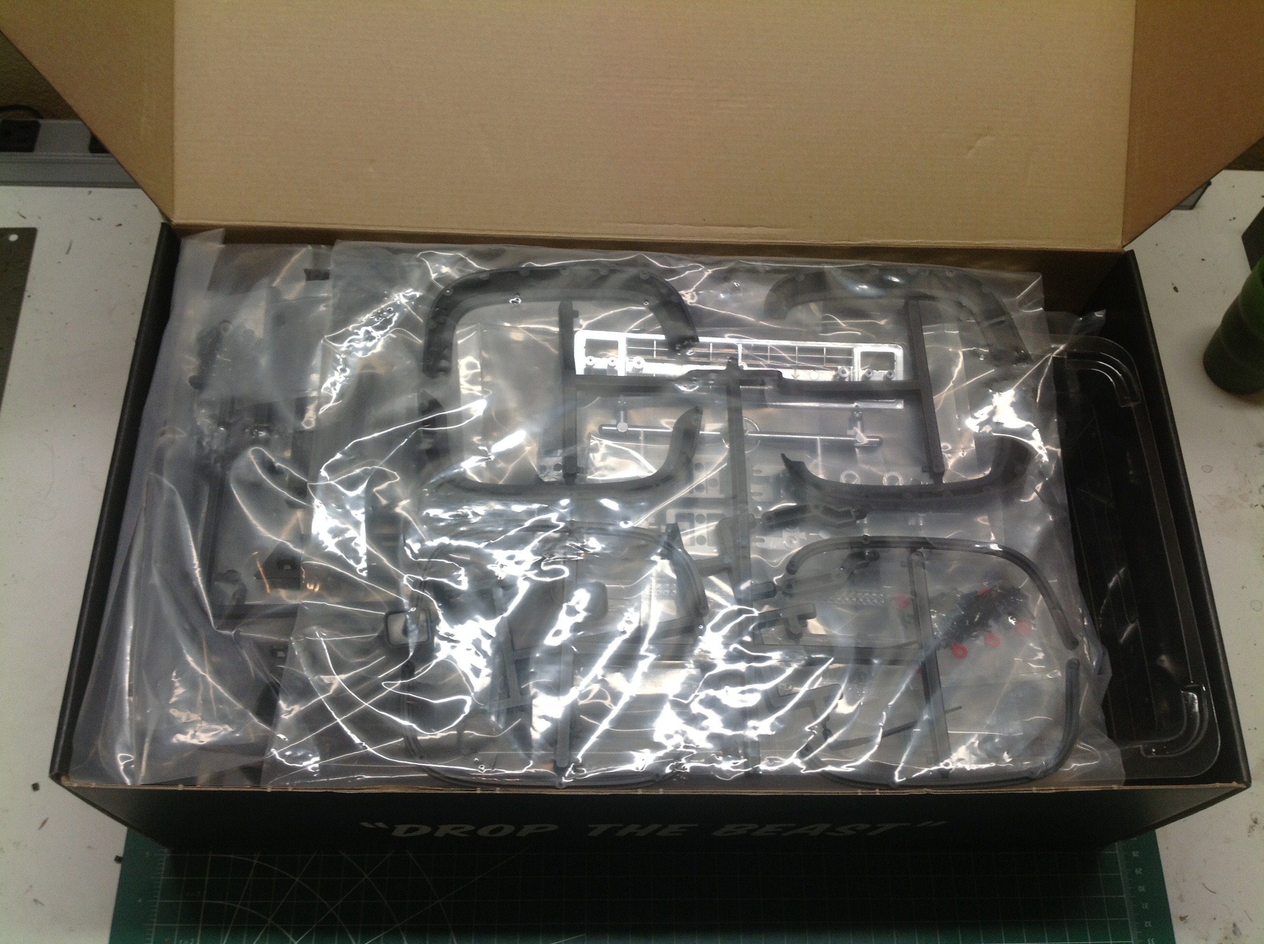
the model or any kind of list of features. The inside isn't very
interesting either. The parts are nicely separated and bagged, but
there is no special presentation.
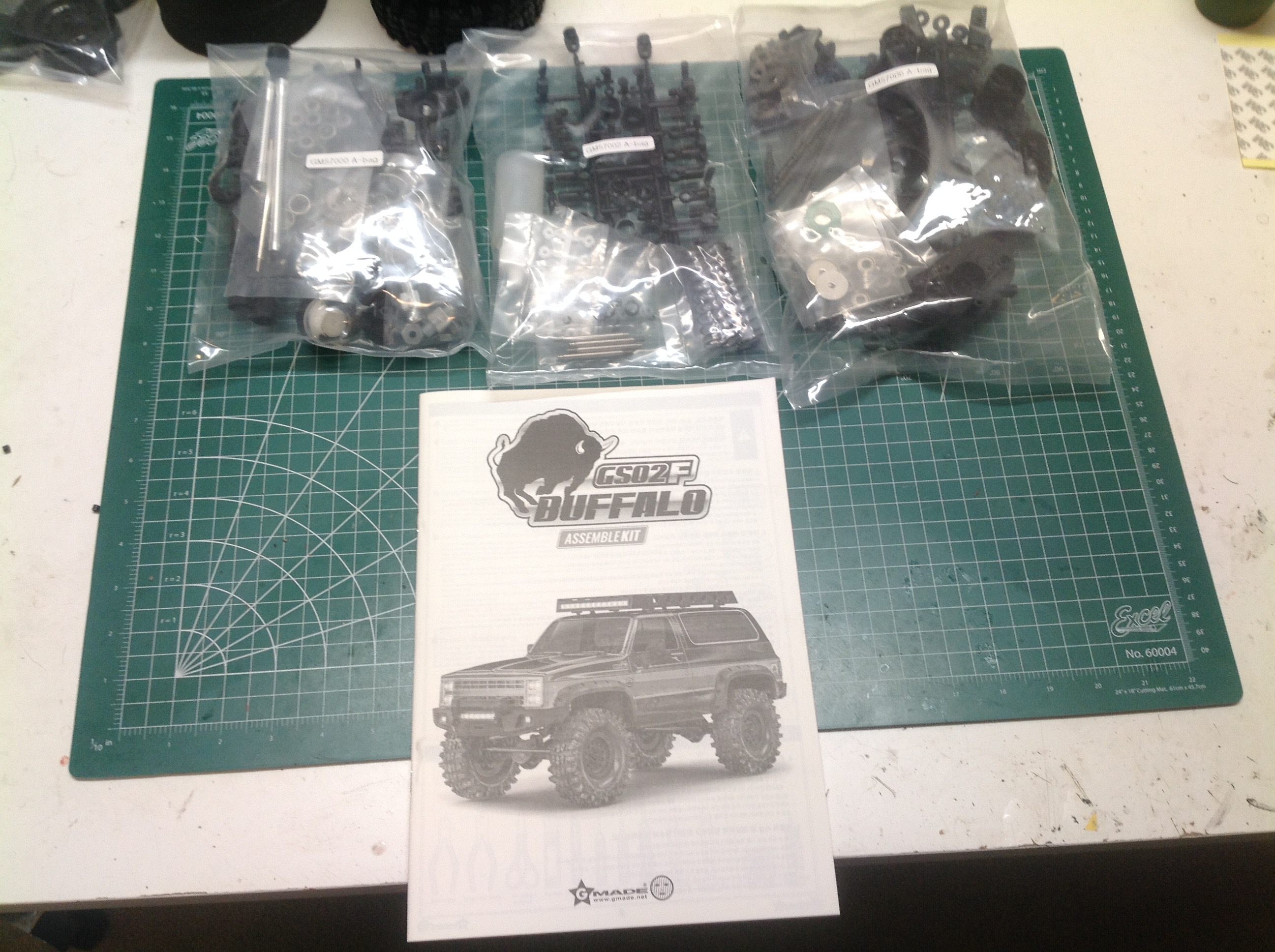
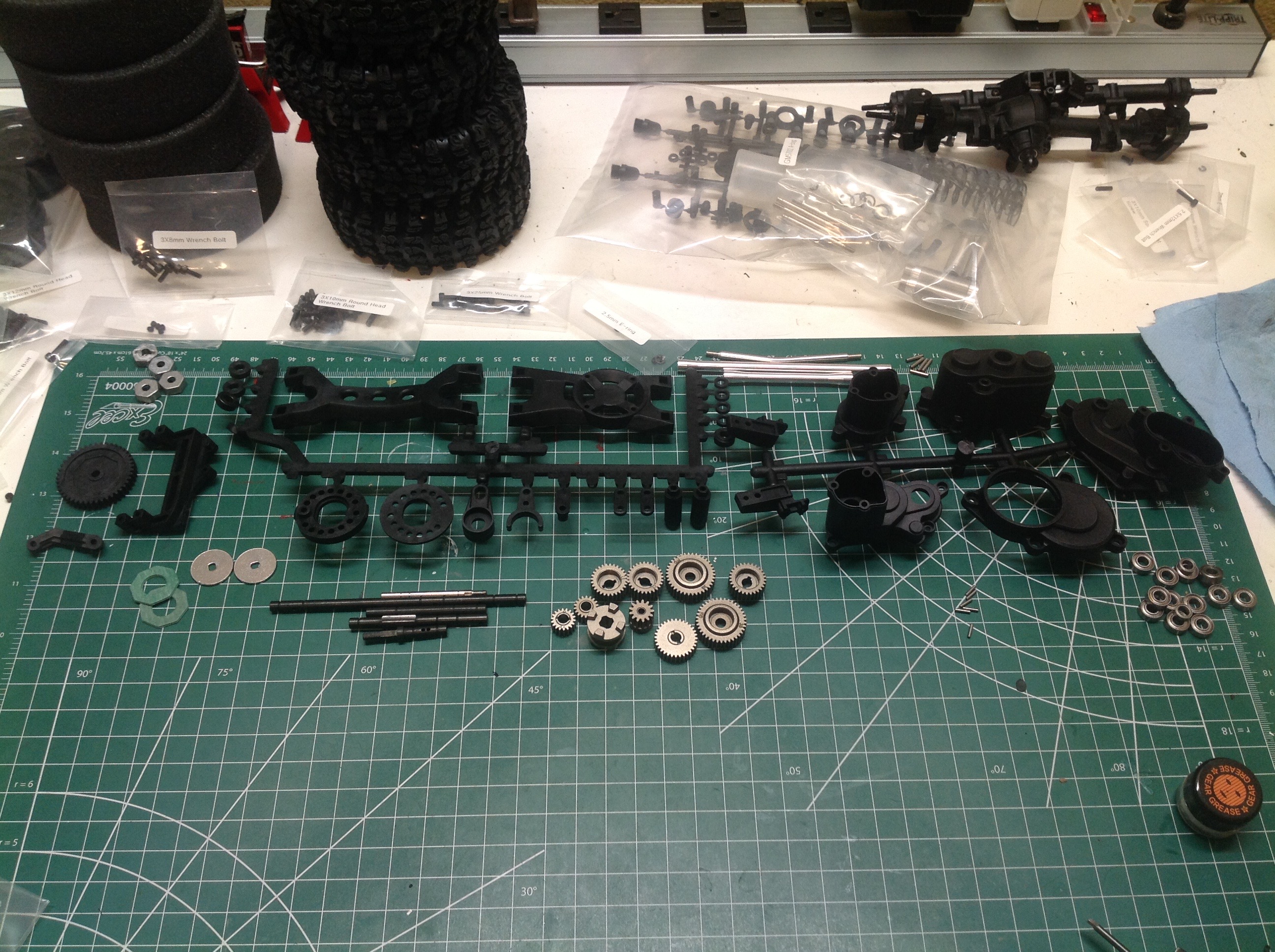
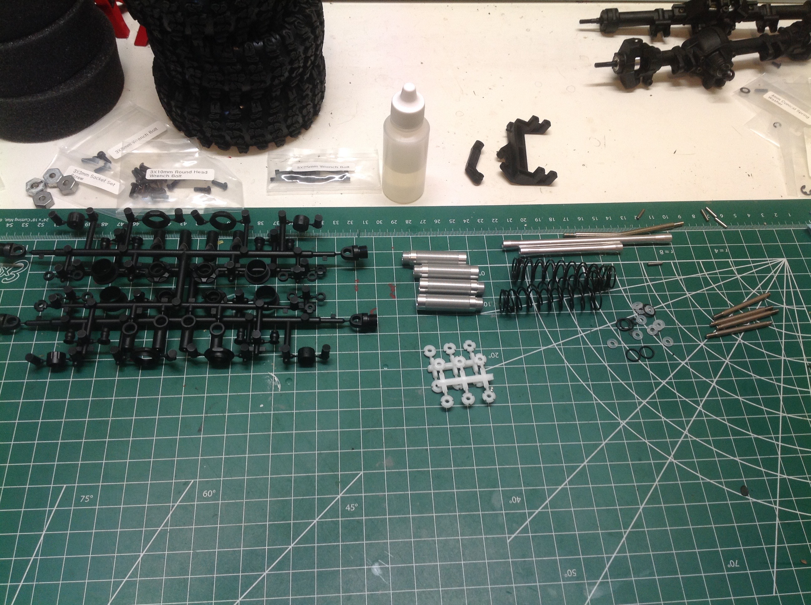
Here I've laid out some of the parts bags on the table along with the instruction manual. The manual is very good.
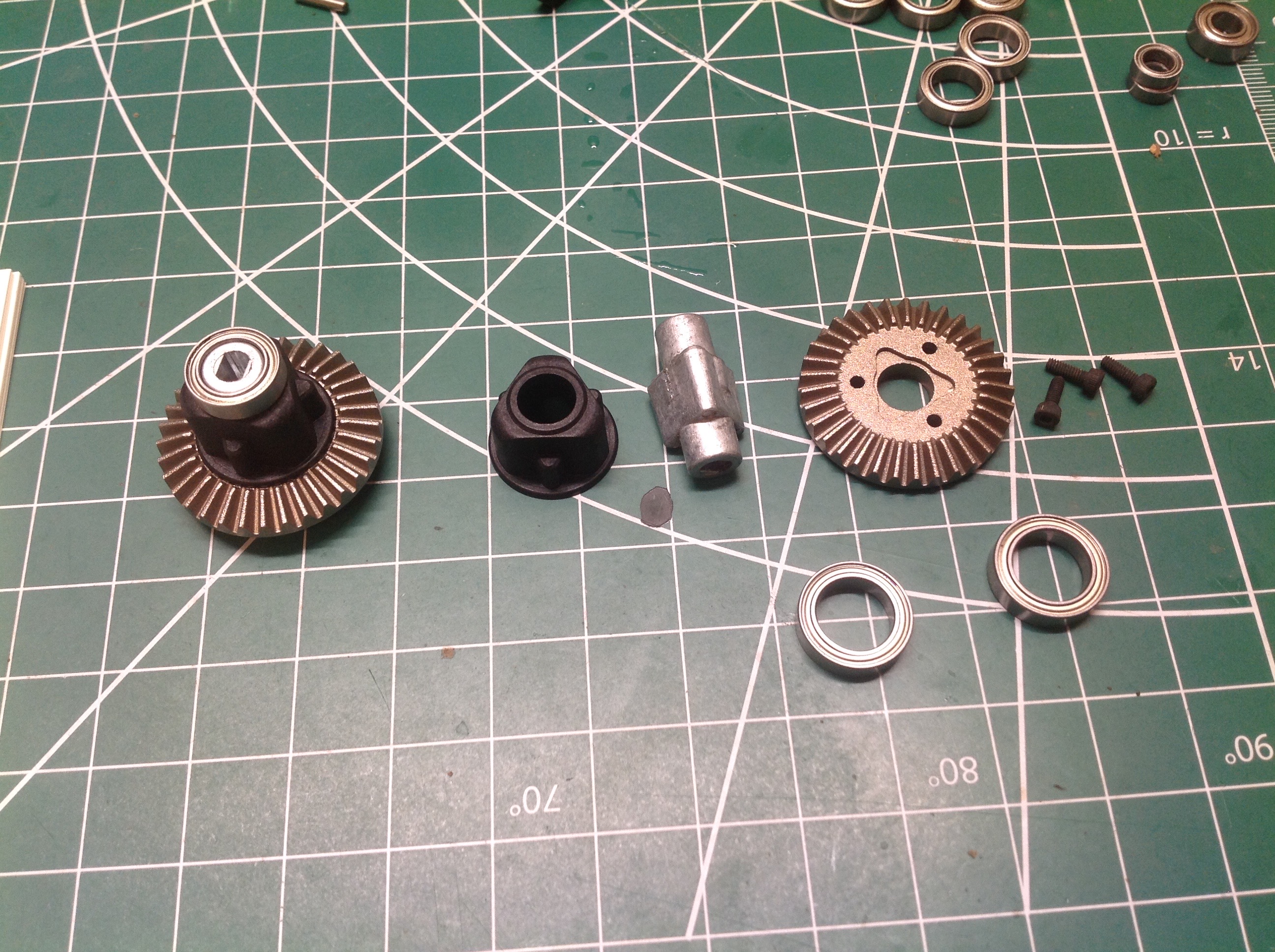
The parts are divided into different bags which roughly correspond to
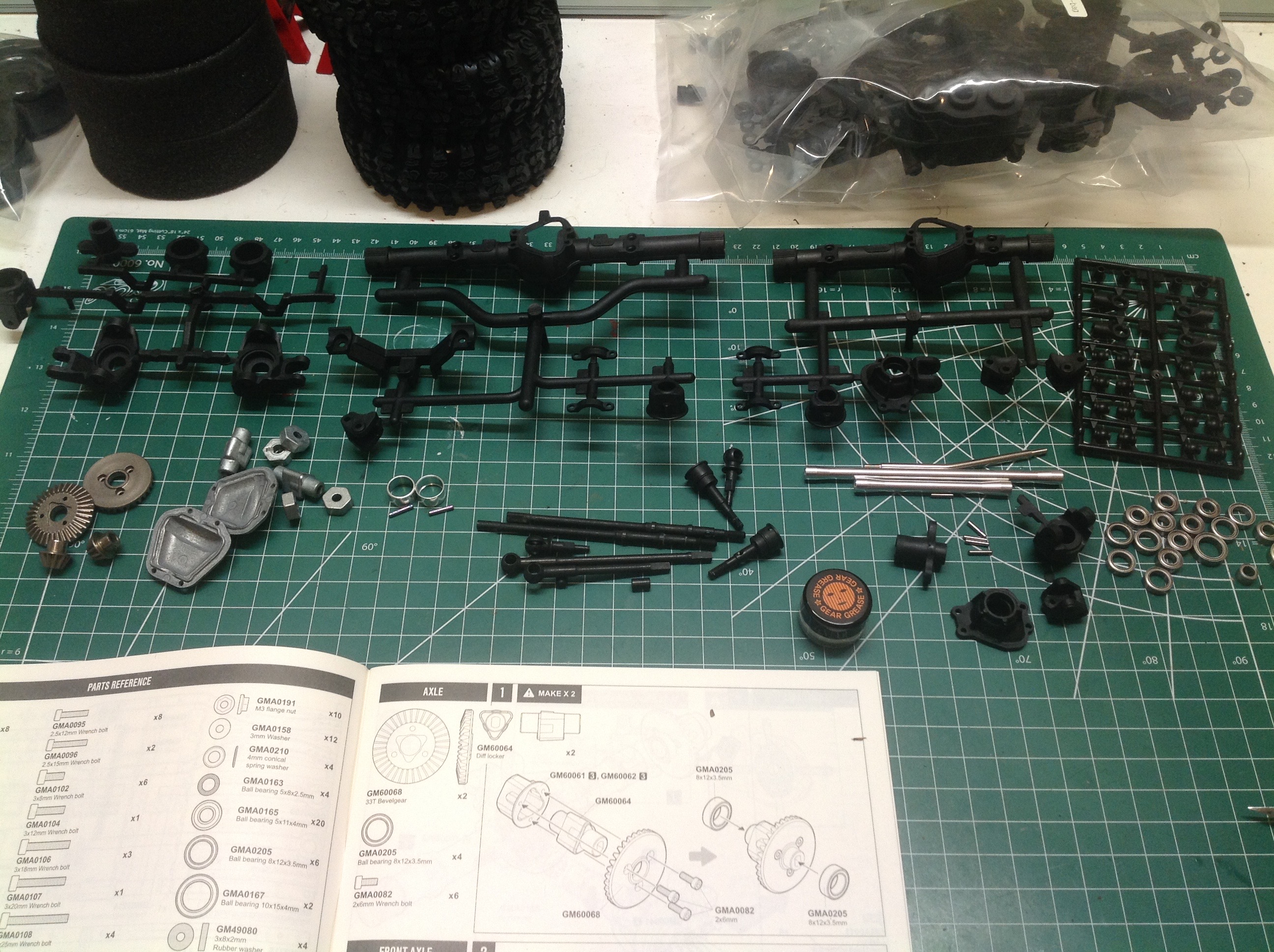
sections of the build manual. The first bag contains the parts
shown which will build the axles. Note the metal gears,
differential covers, and ball bearings.
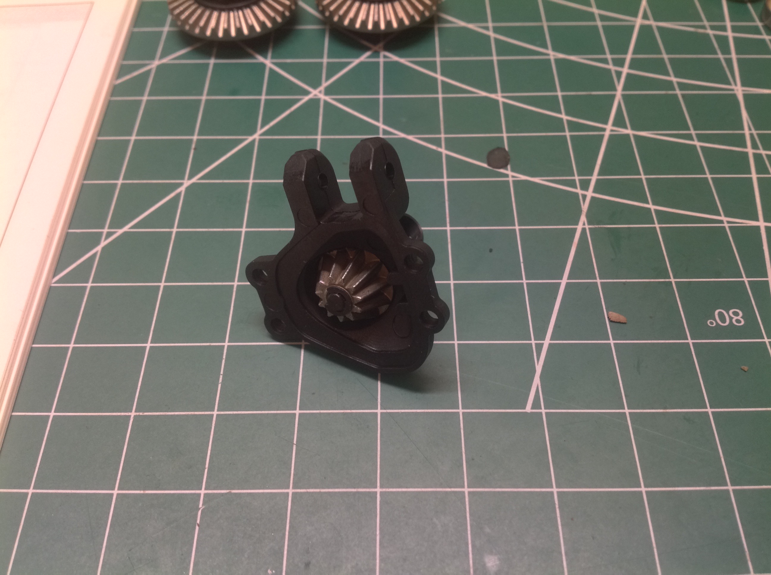
This model uses front and rear lockers which are assembled as shown on
the left. The metal locker slides into a plastic housing which
bolts to the steel ring gear. There is no difference between front
and rear. On the right you can see the pinion gear installed into
the third member which doubles as a link mount.
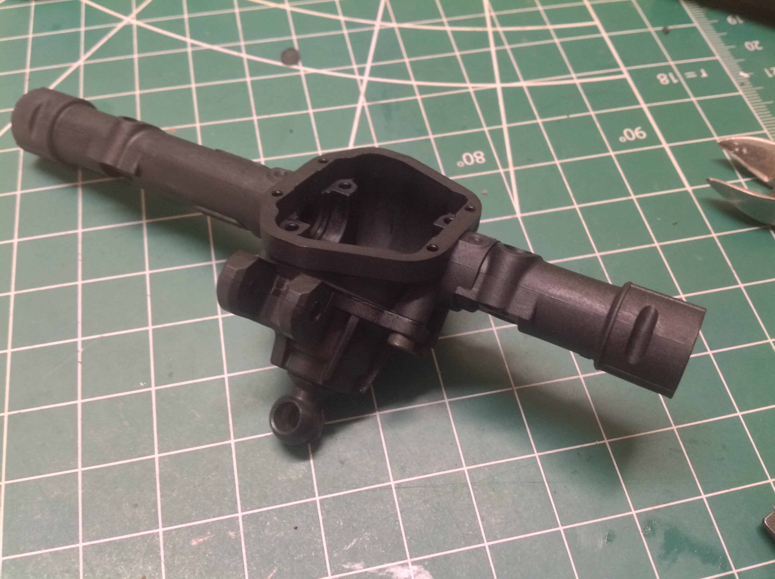
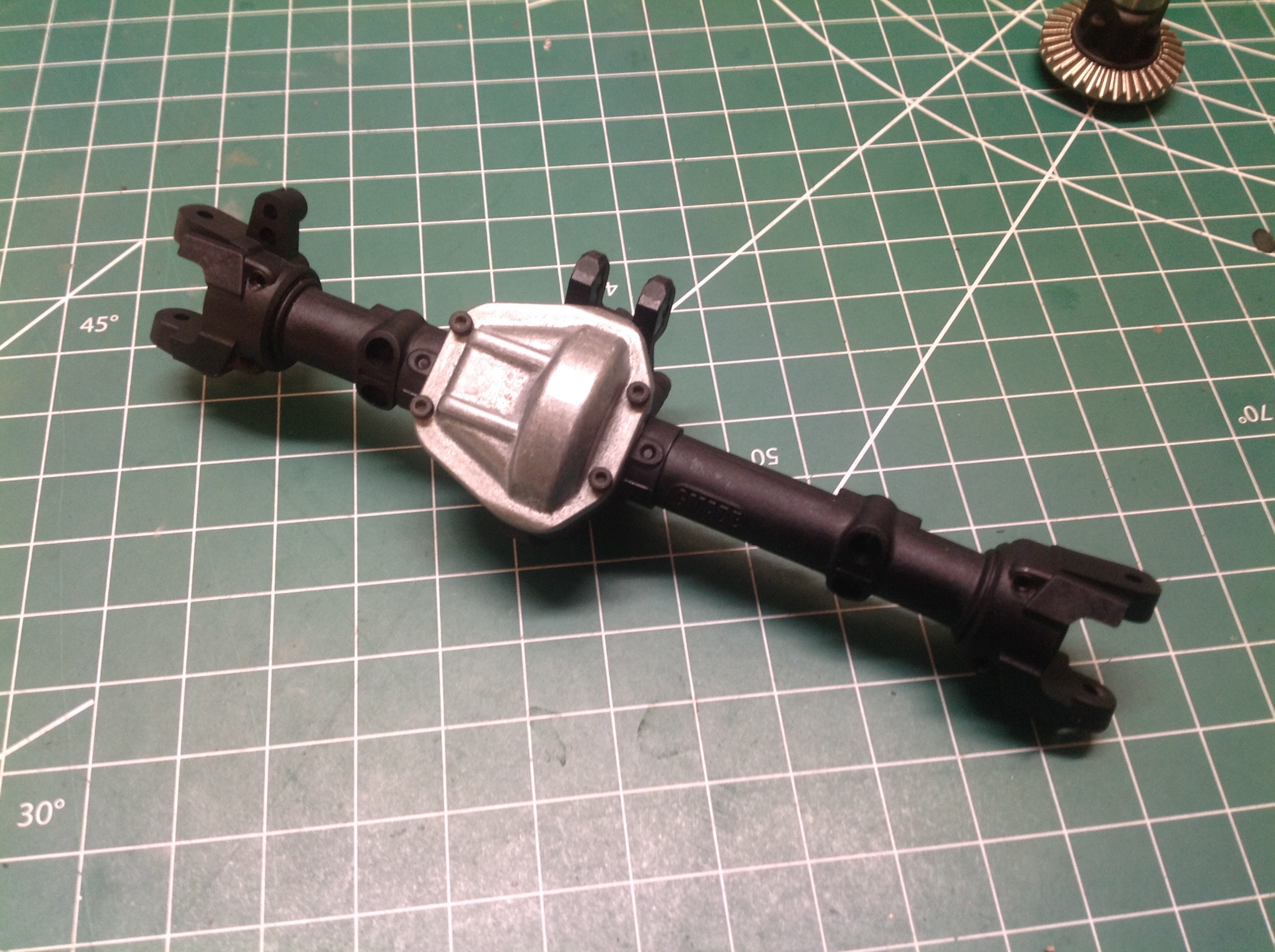
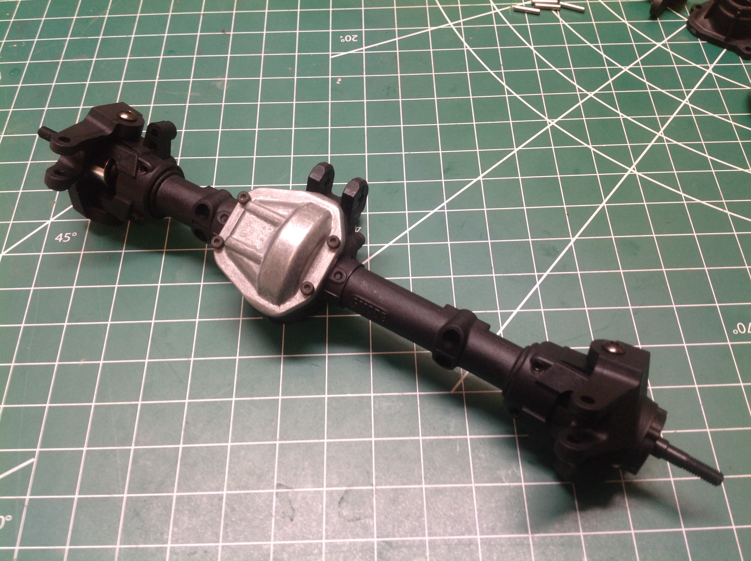
Now the locker can be installed into the axle housings. The
housings are strong, glass reinforced plastic. The third member
bolts on first, then the locker is installed, and finally the cast metal
differential cover is installed. The front axle assembly is
shown. Note that the pumpkin is off center.
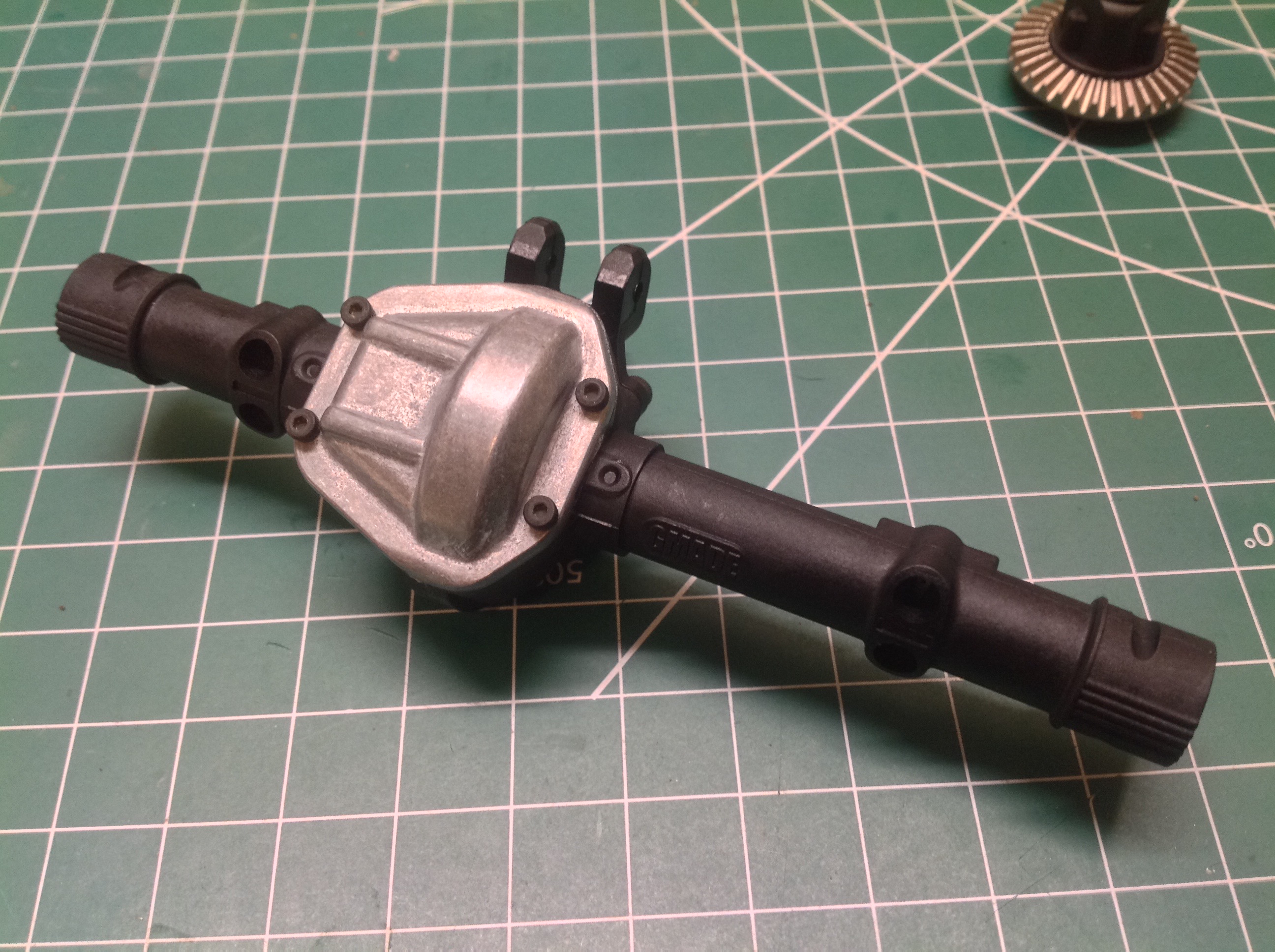
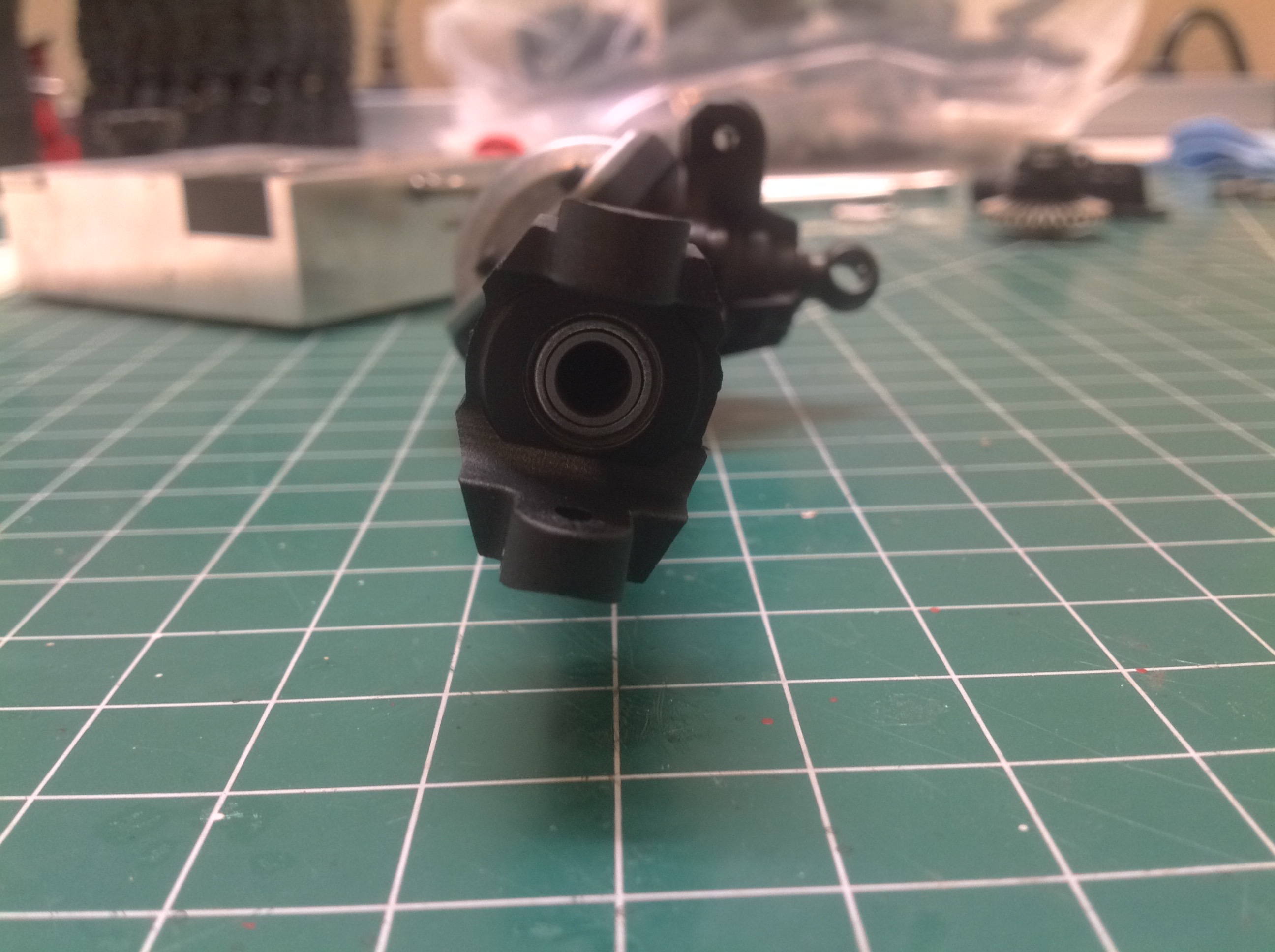
Now the C-hubs can be installed onto the axle housings. On the
right you can see the caster angle of the hubs. Note also that the
diff cover does not point straight forward but is actually angled
upward which should help it avoid contacting obstacles.
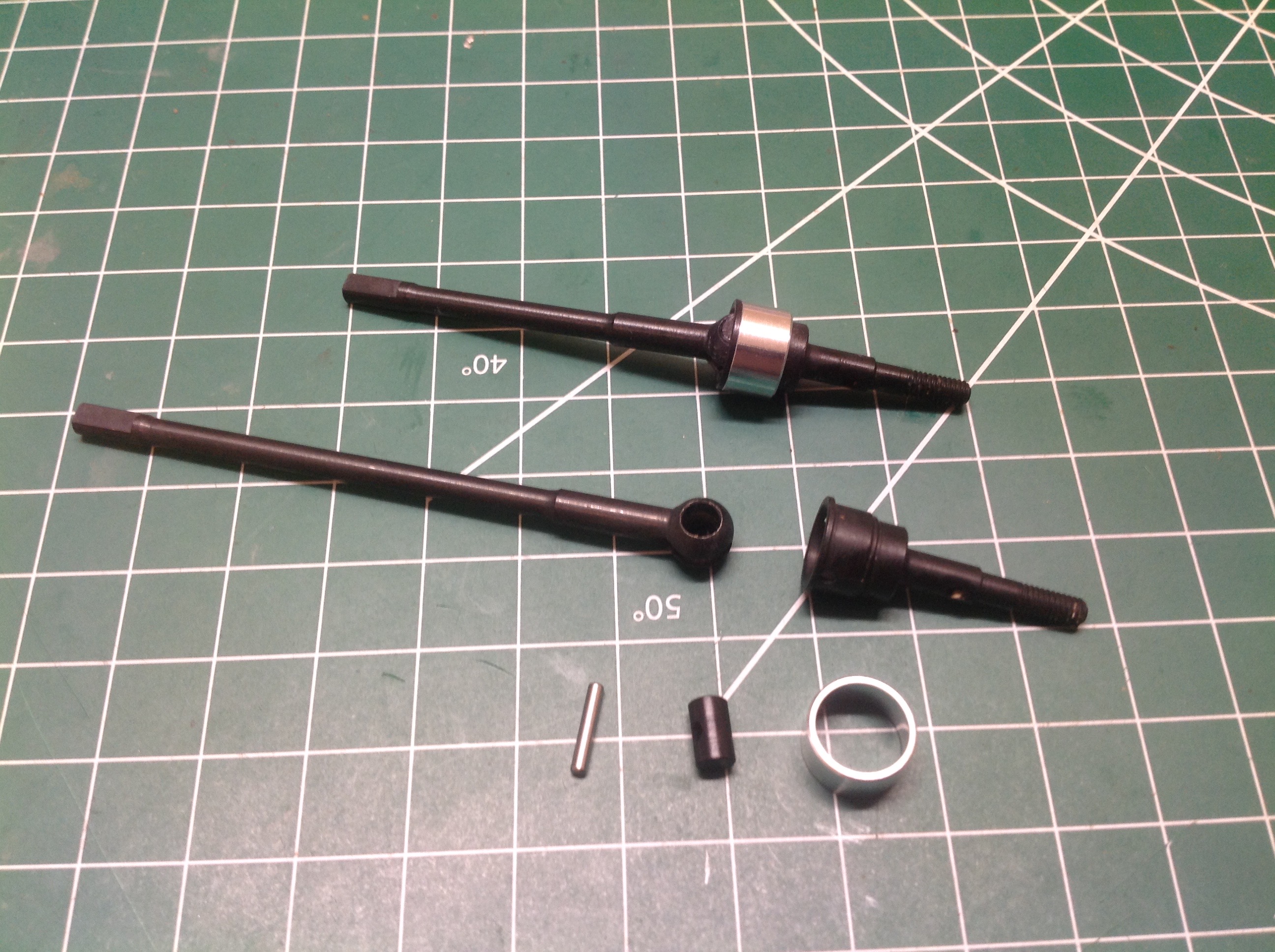
The steel axles have CVD ends for steering and are assembled as
shown. I really like the quality of these parts. The axles
are inserted into the housing from the outside and slide into the diff
locker with flattened ends.
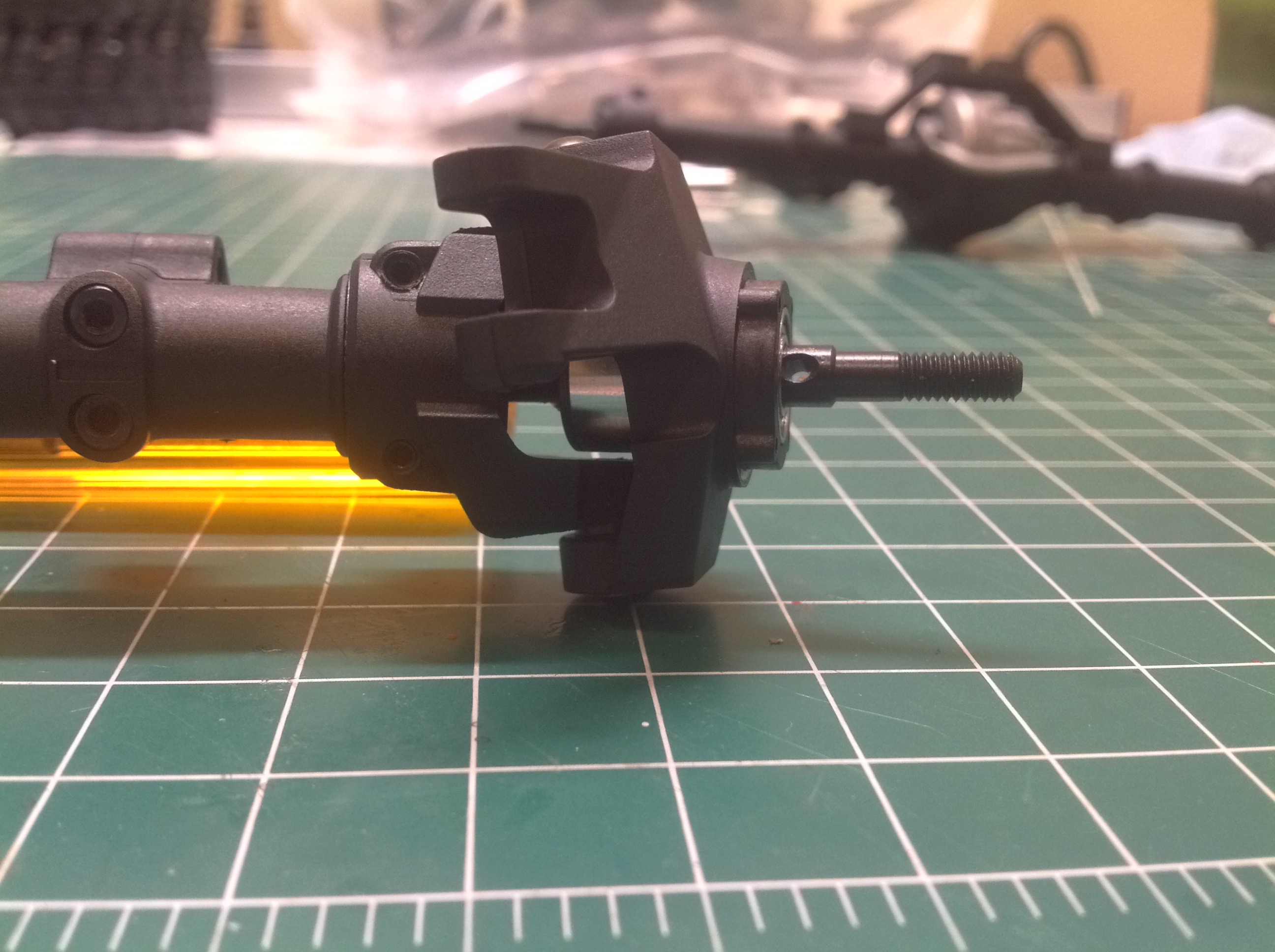
Now the steering knuckles can be installed. These are beefy
plastic parts with integral bearings. The picture on the right
highlights the kingpin inclination.
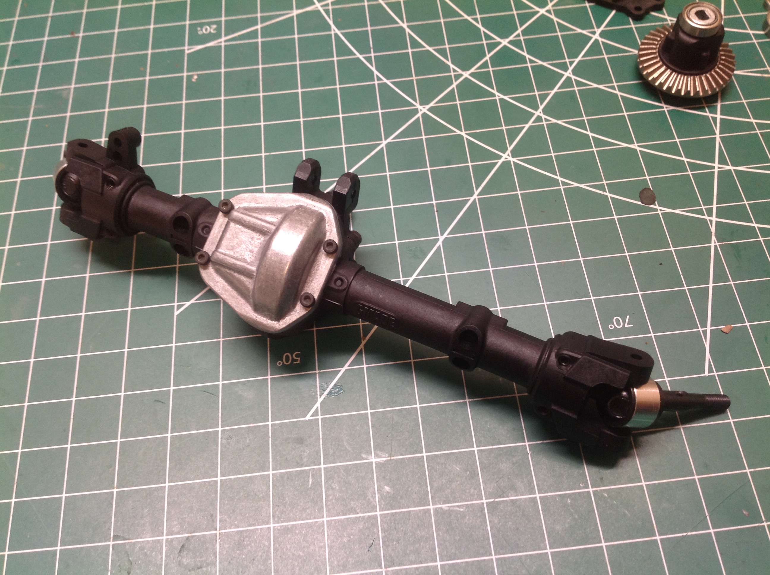
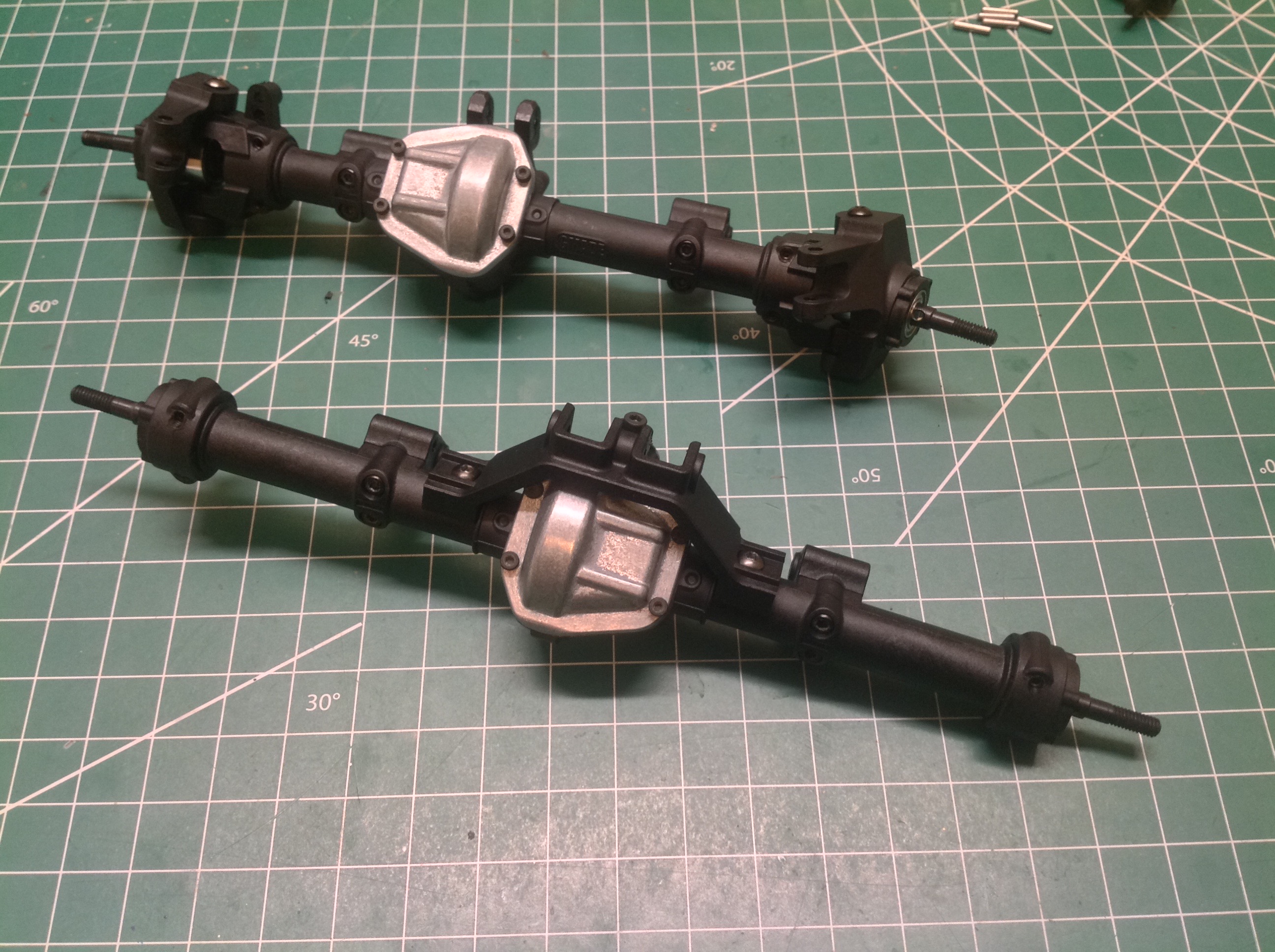
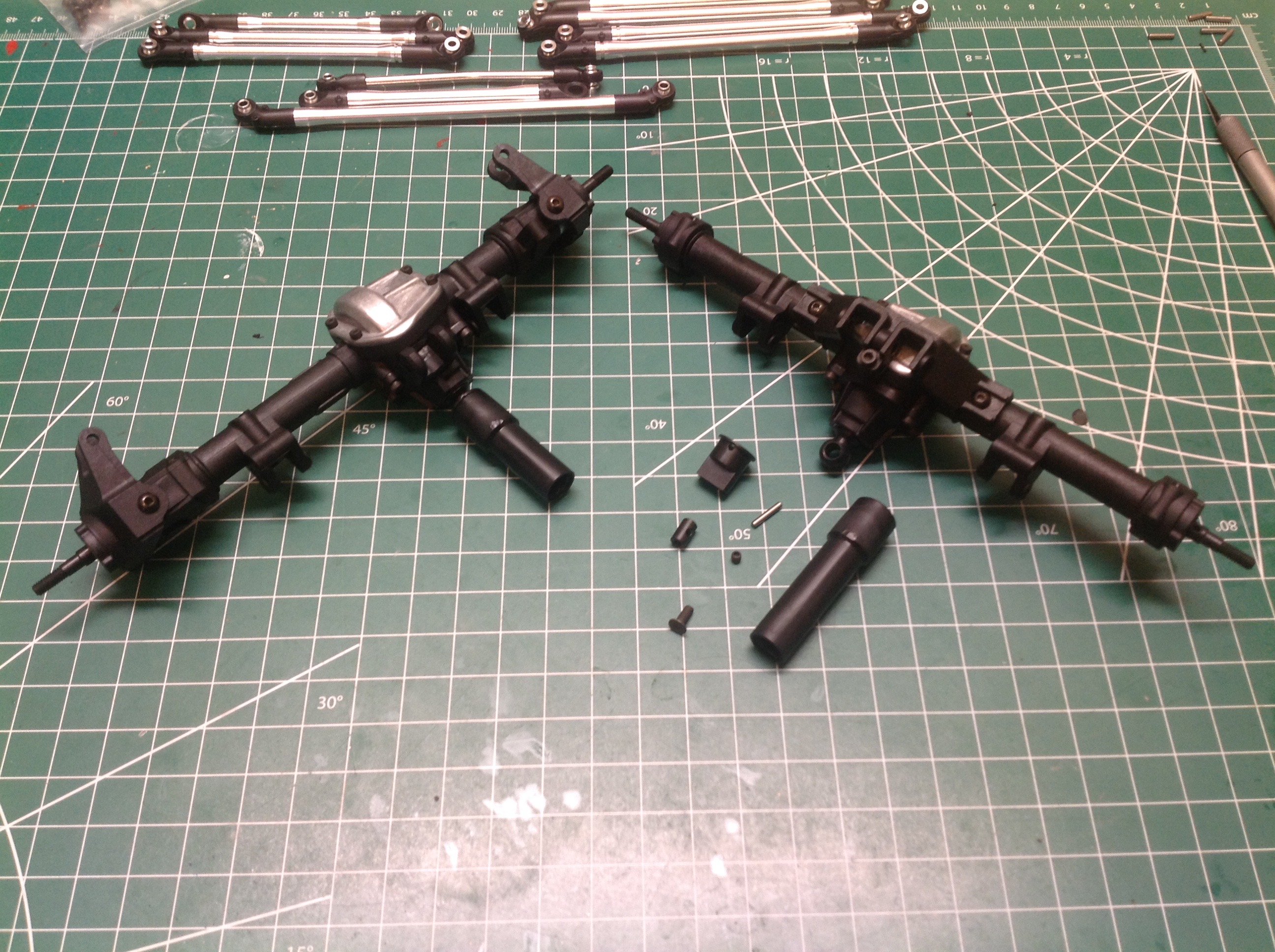
The completed front and rear axles are shown here. They have much
in common, but the pumpkin of the rear axle is centered and it has
straight hubs instead of steering knuckles. The rear axle also
sports a truss for upper link support. The front will have only a
single upper link since it uses a panhard bar.
The second bag contains the parts for the transmission. There are a lot of metal gears here along with ball bearings and a slipper clutch.
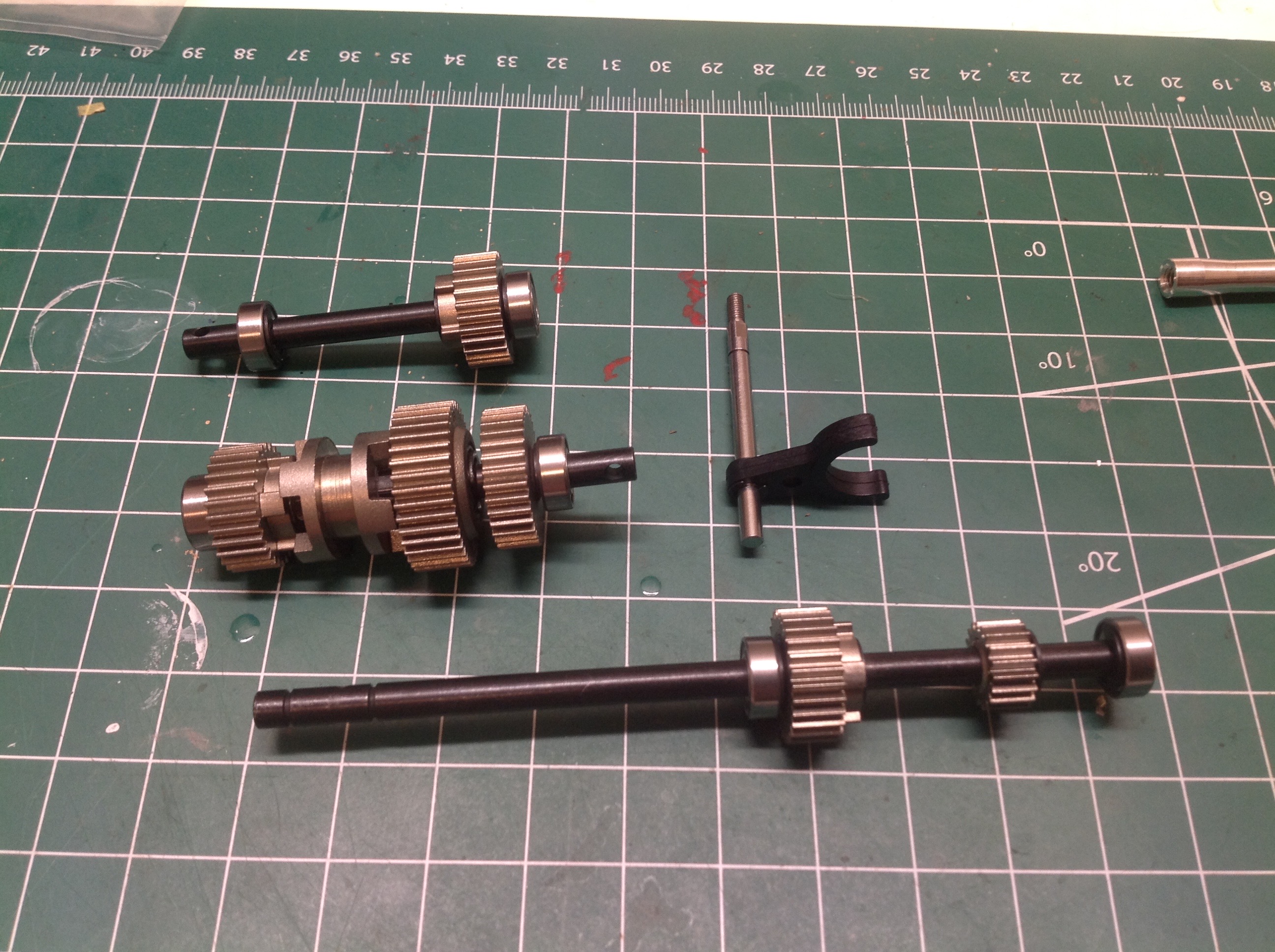
Here are three of the main transmission shafts. The lower shaft on
the left will be the input from the motor. Both gears are locked
to this shaft and will drive the two speed transmission. The
middle shaft meshes with the input shaft in two places. Both of
these gears rotate freely on the shaft. The central shifting ring
is locked to the shaft and can be slid forward or back to engage one
speed or the other. The third gear on the shaft (far right of the
central shaft) is the output to the next stage. The upper shaft is
the output to the front drive shaft. The central shaft outputs to
the rear drive shaft. The fact that the front and rear outputs
are on different shafts has a couple of effects. One is that the
outputs are offset which drives the need for an off-center front
pumpkin. The front and rear drive shafts also rotate in opposite
directions which helps minimize torque roll. Finally, the front
and rear have different gear ratios resulting in a mild front
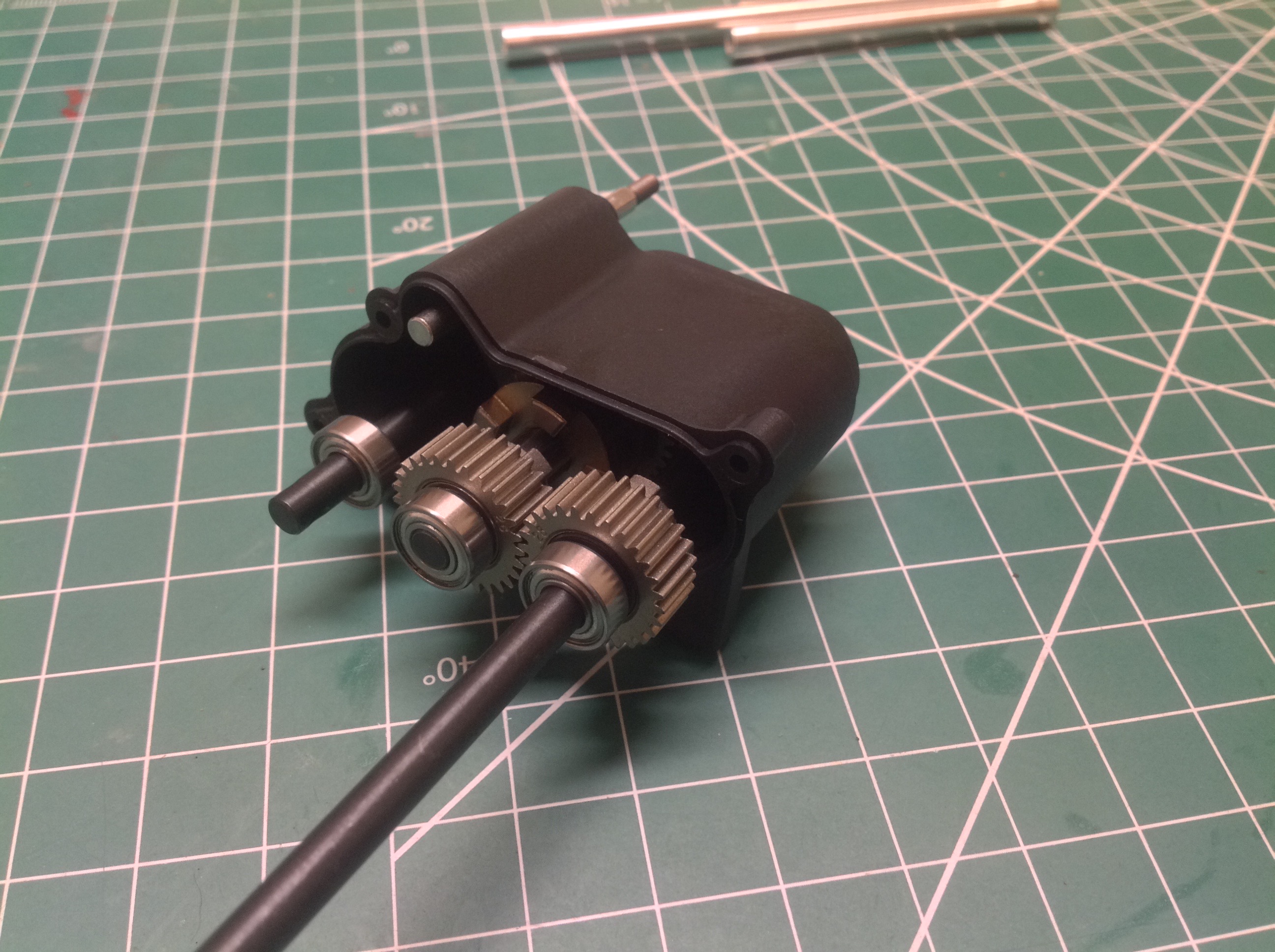
overdrive. The right hand image shows these shafts installed into
the first transmission housing.
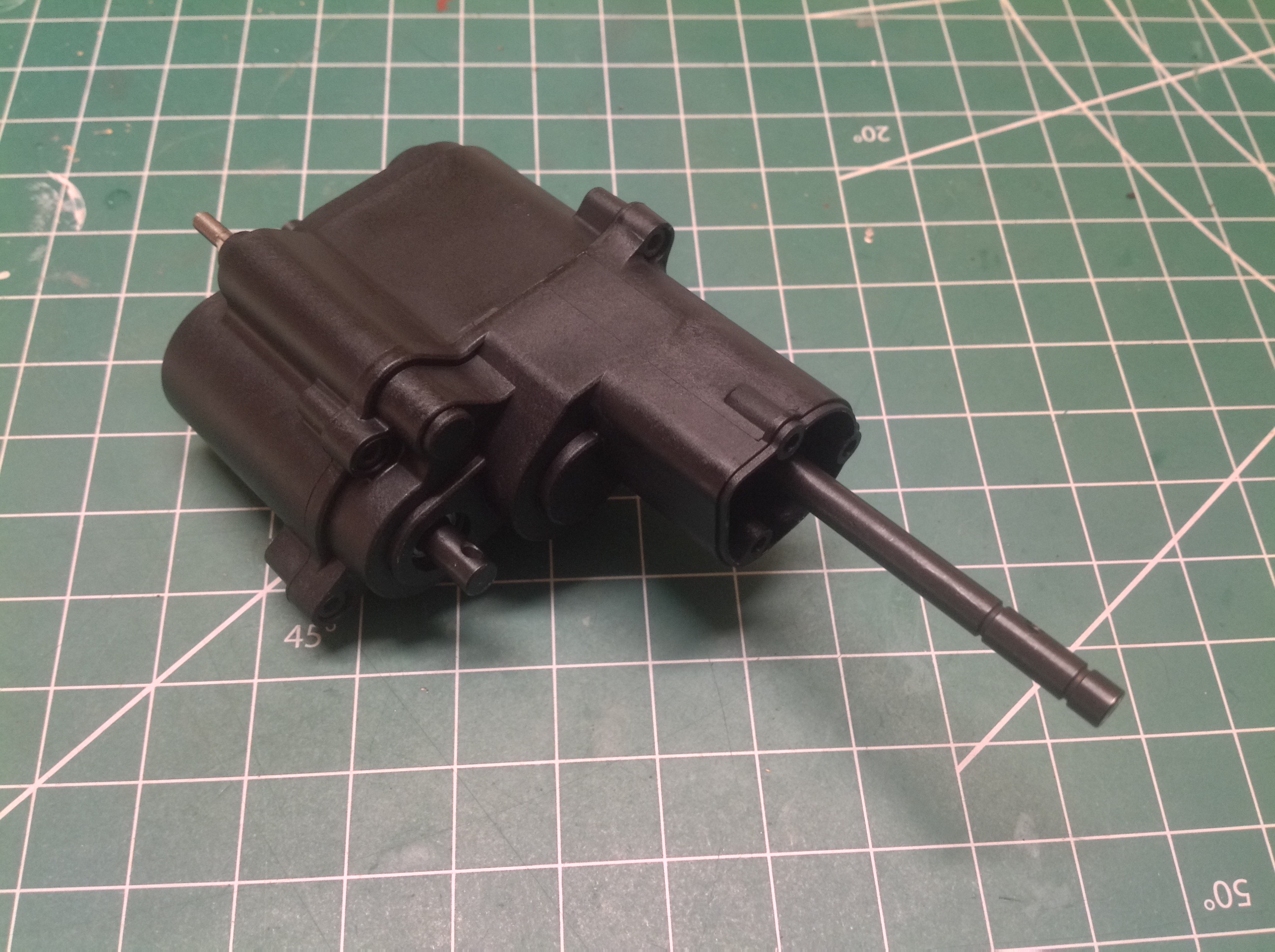
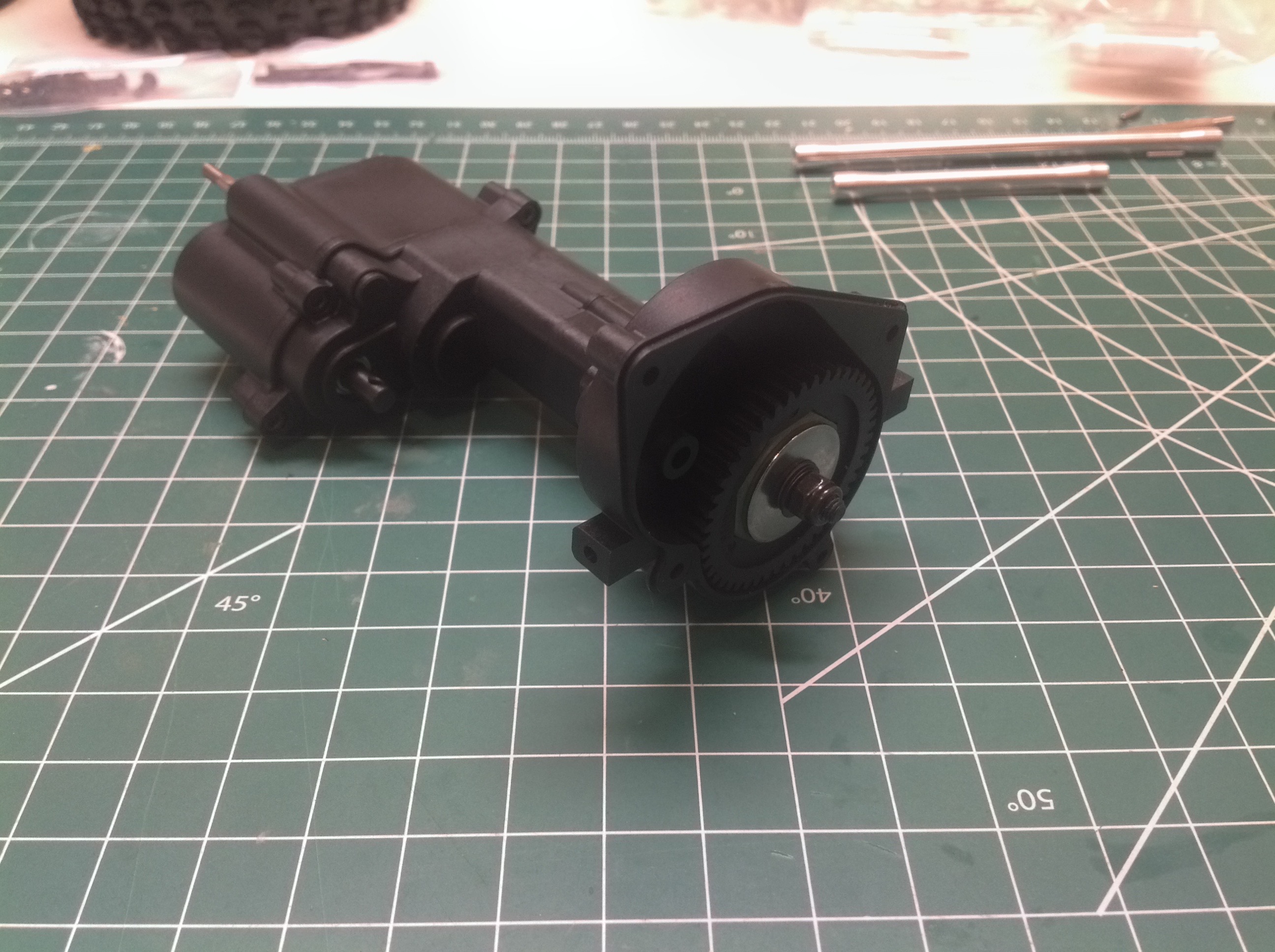
Now a couple of additional housings are installed which extend the
transmission far forward. The gears you see on the right are an
additional reduction prior to reaching the motor. The left hand
shaft with the smaller gear) will have the spur attached to it.
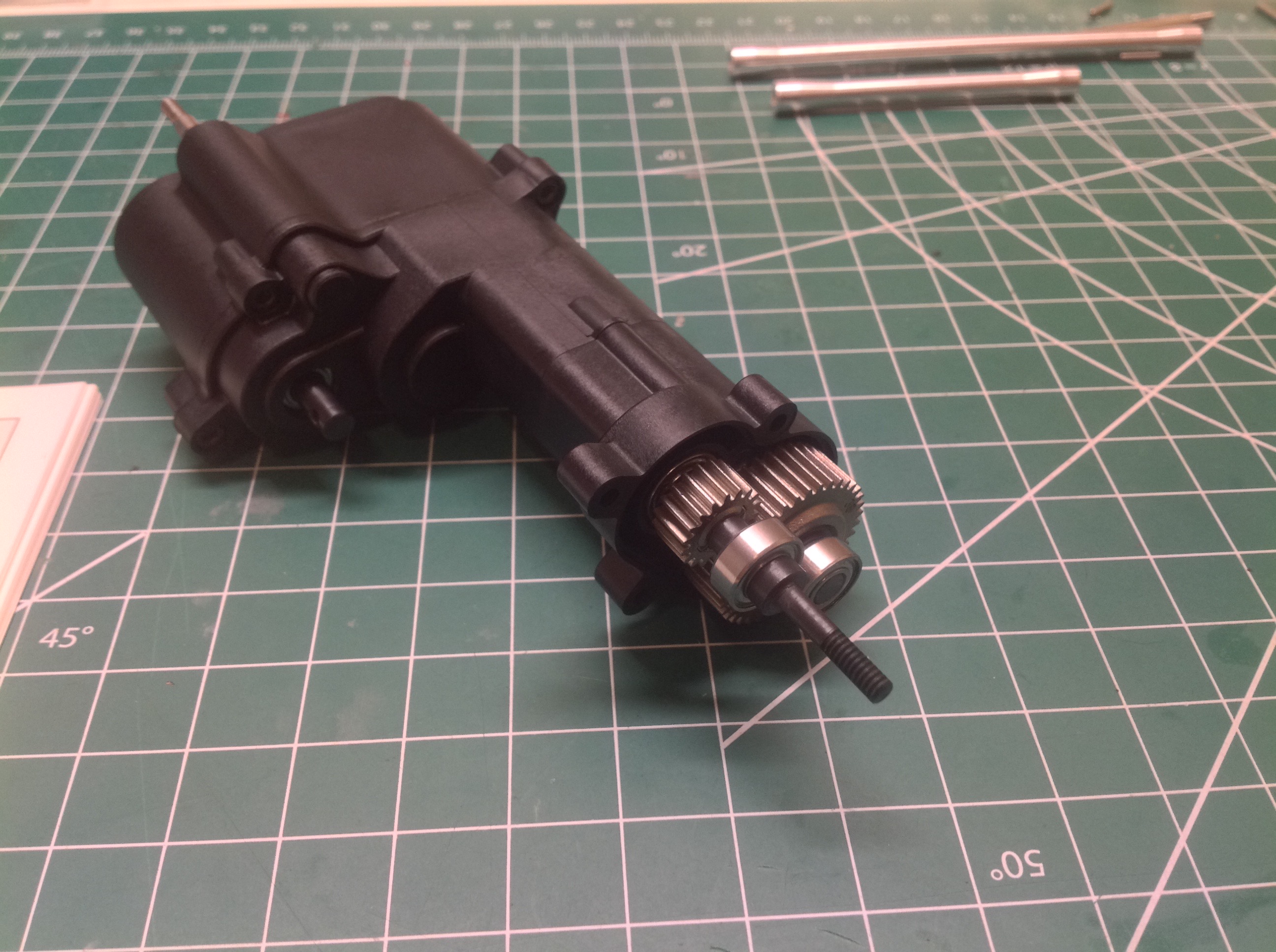
This picture shows the slipper clutch which is built into the spur
gear. It is not particularly easy to access later so it is
important to get the setting right now.
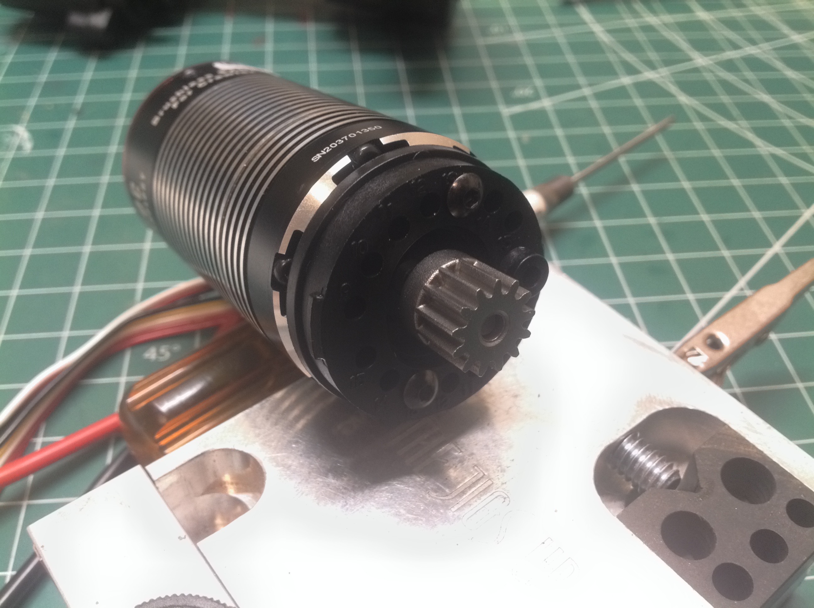
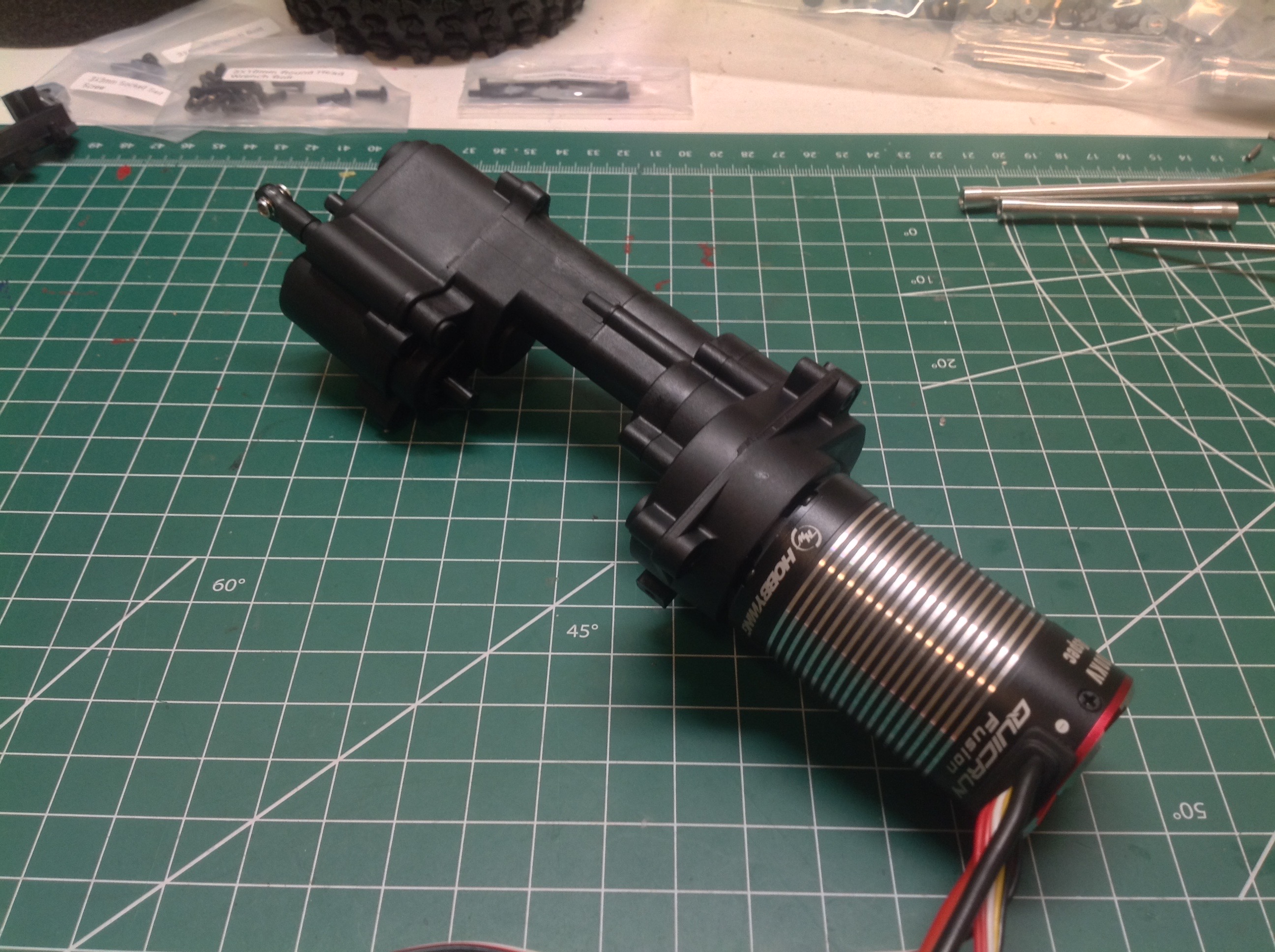
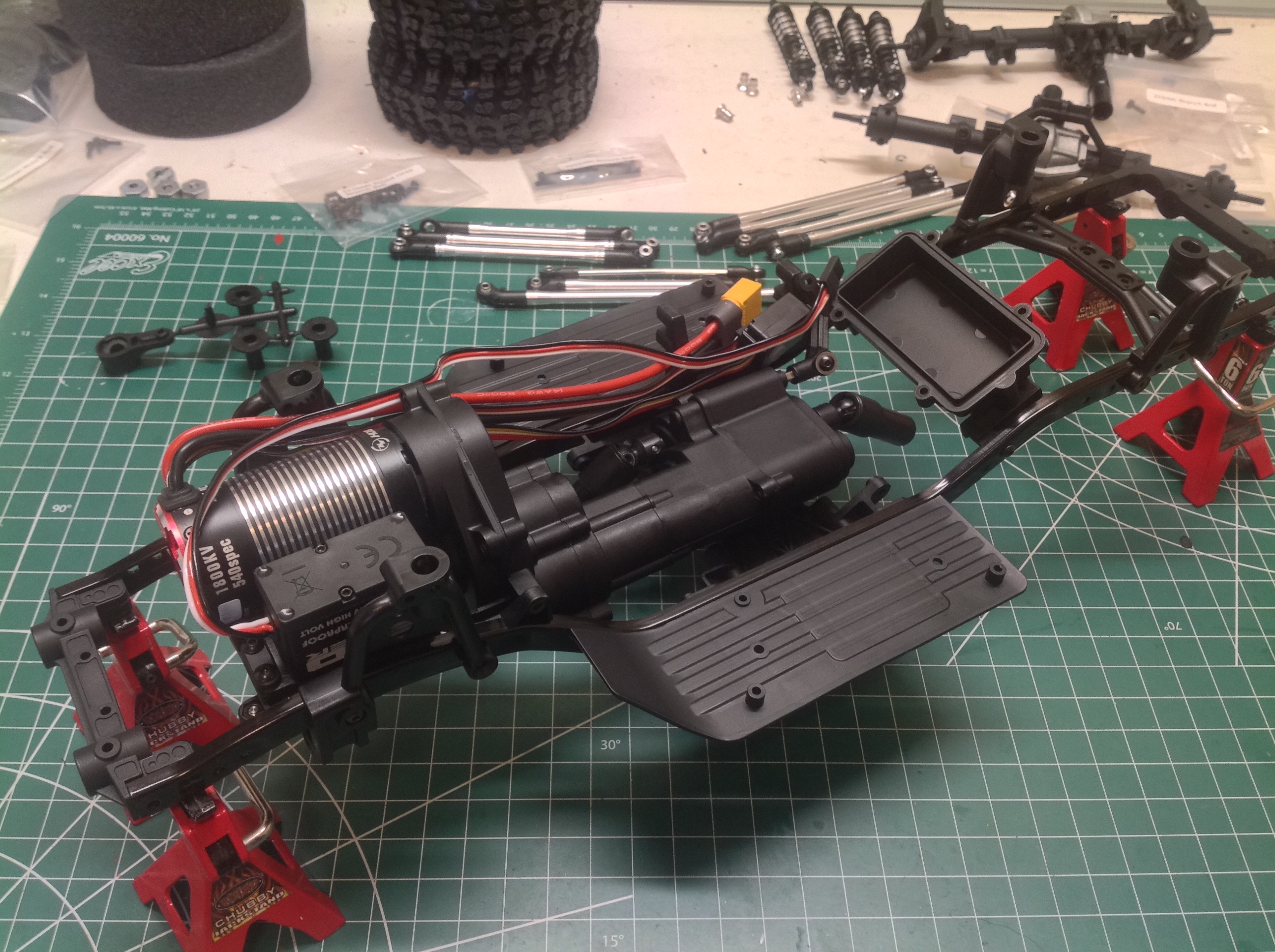
Now the motor can be installed. I used a Hobbywing Fusion system
with the ESC built into the motor. This makes for a long motor,
but otherwise saves on electronic space. The motor mount has a
determinant assembly with different mounting holes for different sized
pinions. A 13T pinion comes with the kit which is what I
used. The final assembly is very heavy.
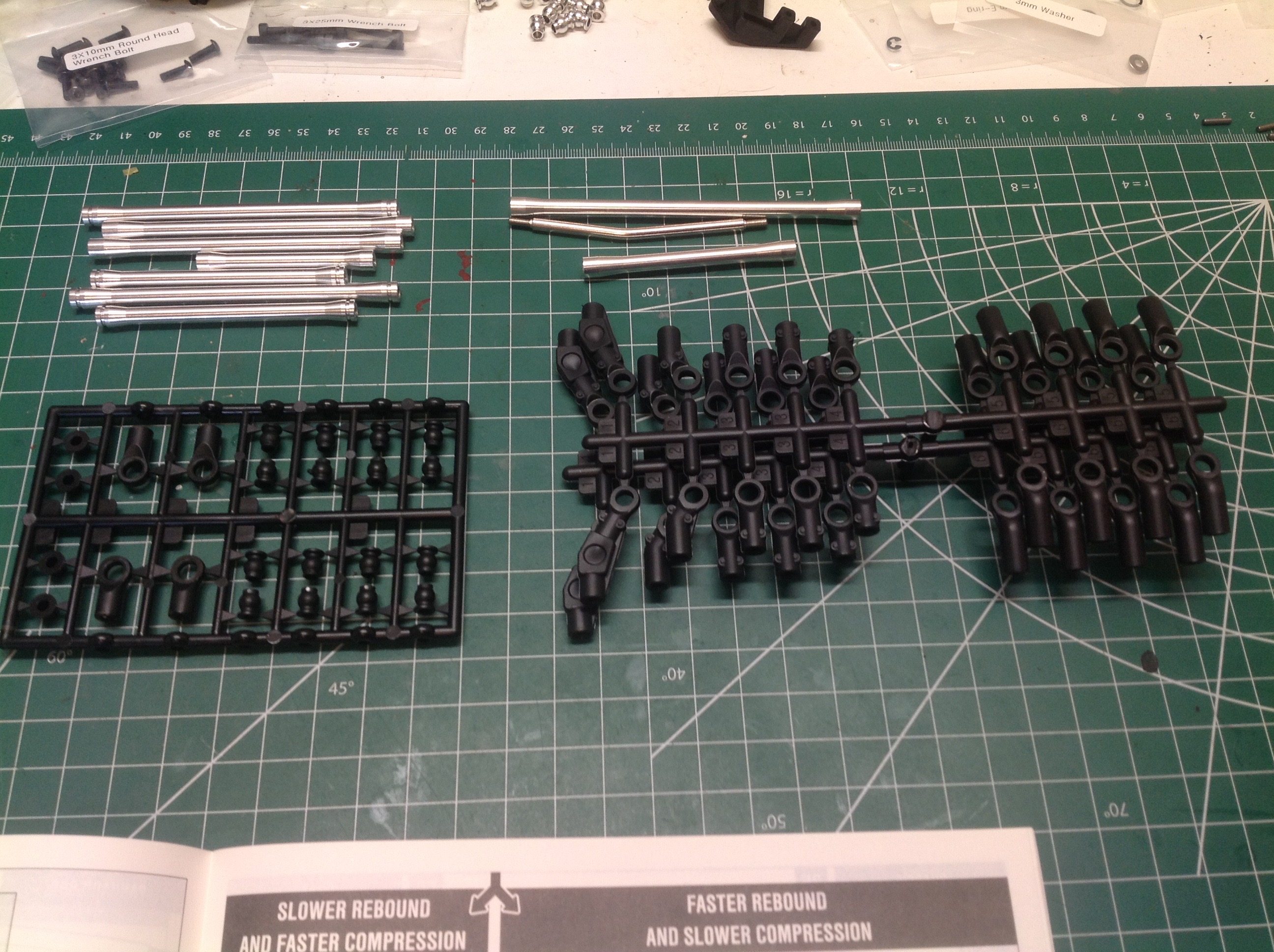
This bag contains the parts for the ten metal links that require
assembly. This part is always pretty tedious. It is
important to keep the links organized because there are subtle
differences between them.
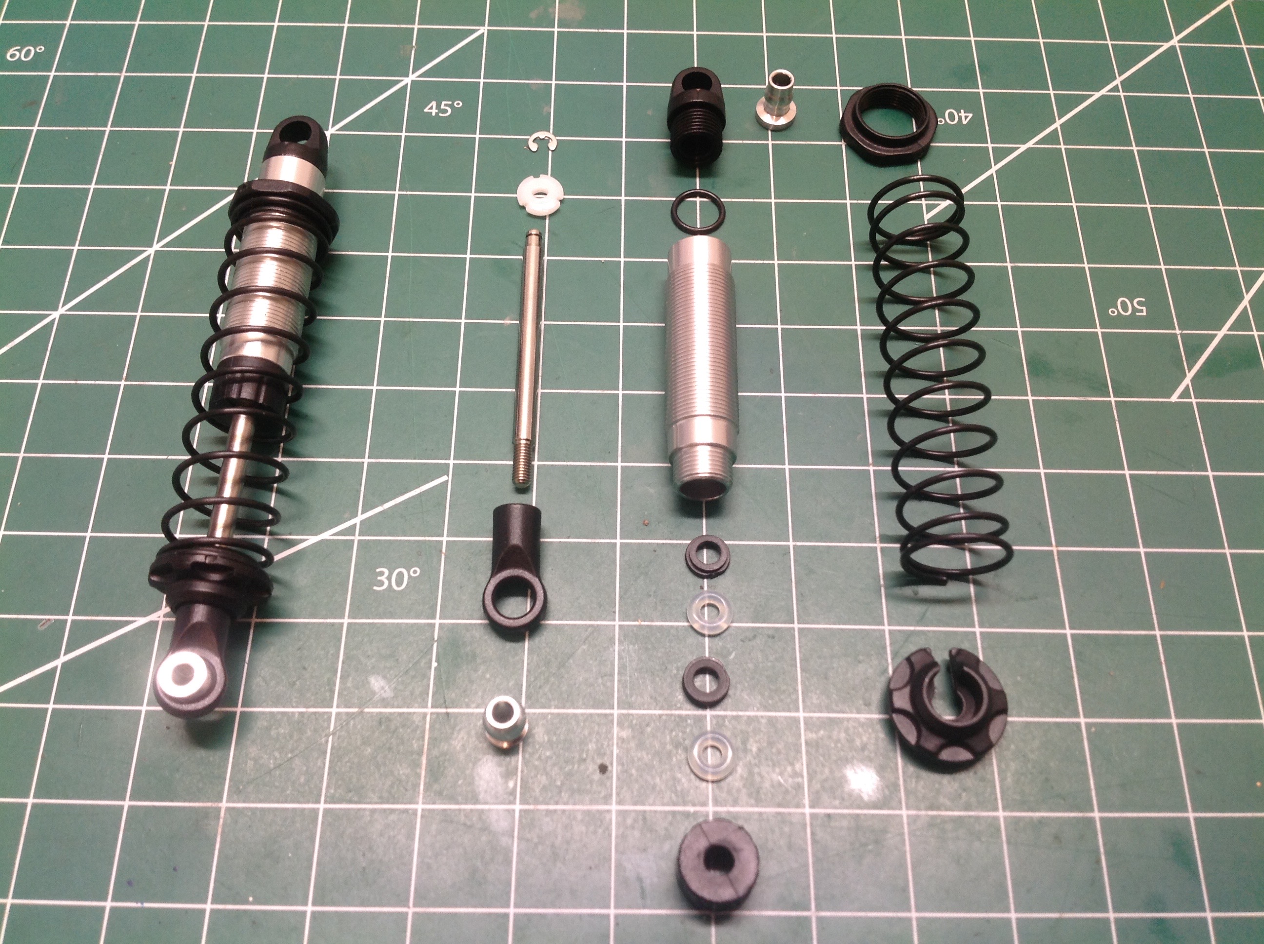
The next set of parts builds the coilover shocks. All four are the same
and use aluminum shock bodies. I'm not sure what weight the kit
supplied oil is, but it is pretty thin.
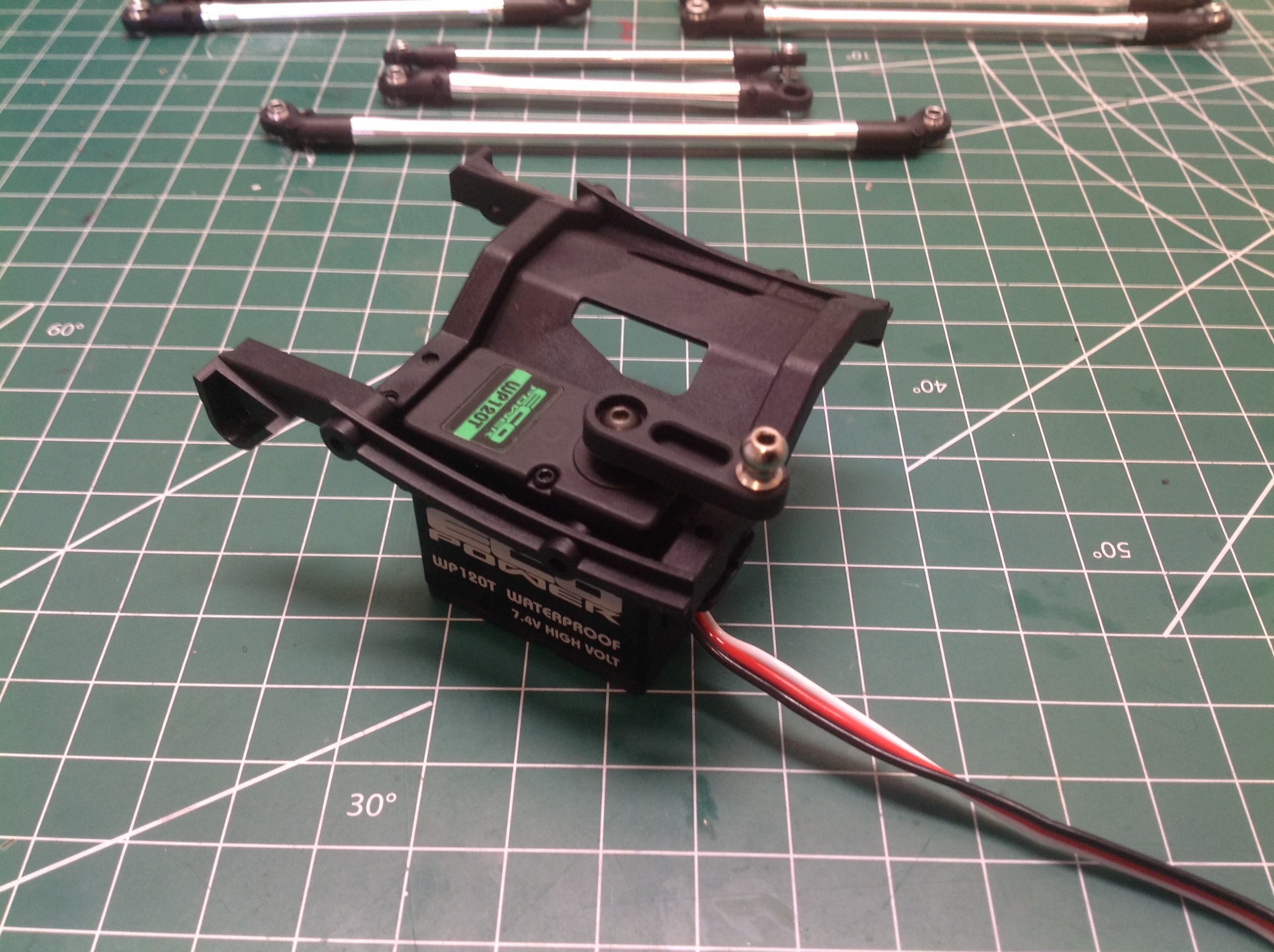
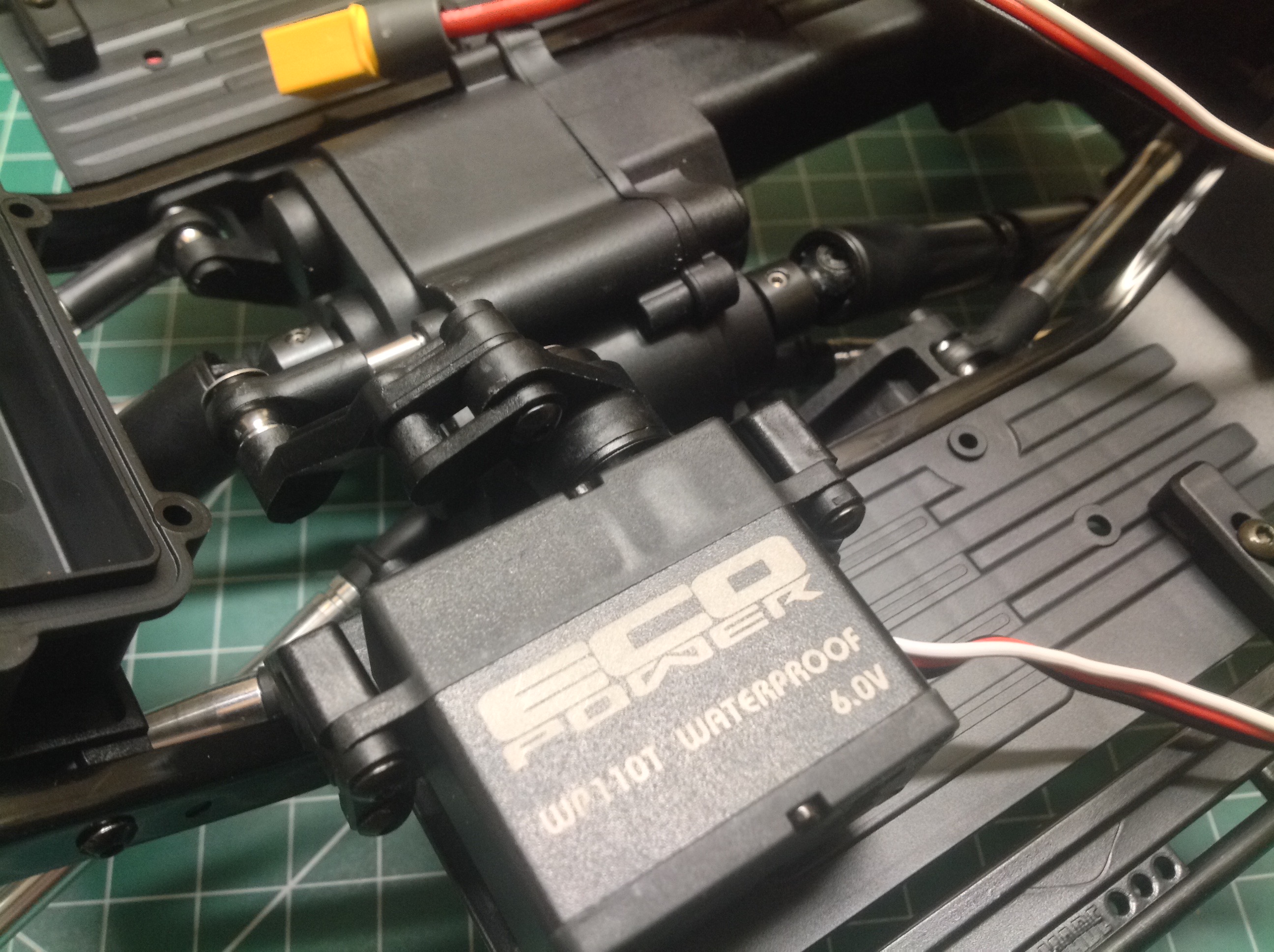
Here is the frame cross member which houses the chassis mounted steering
servo. I chose an Eco-power waterproof digital servo with
adequately high torque. The kit includes a solid plastic servo
horn.
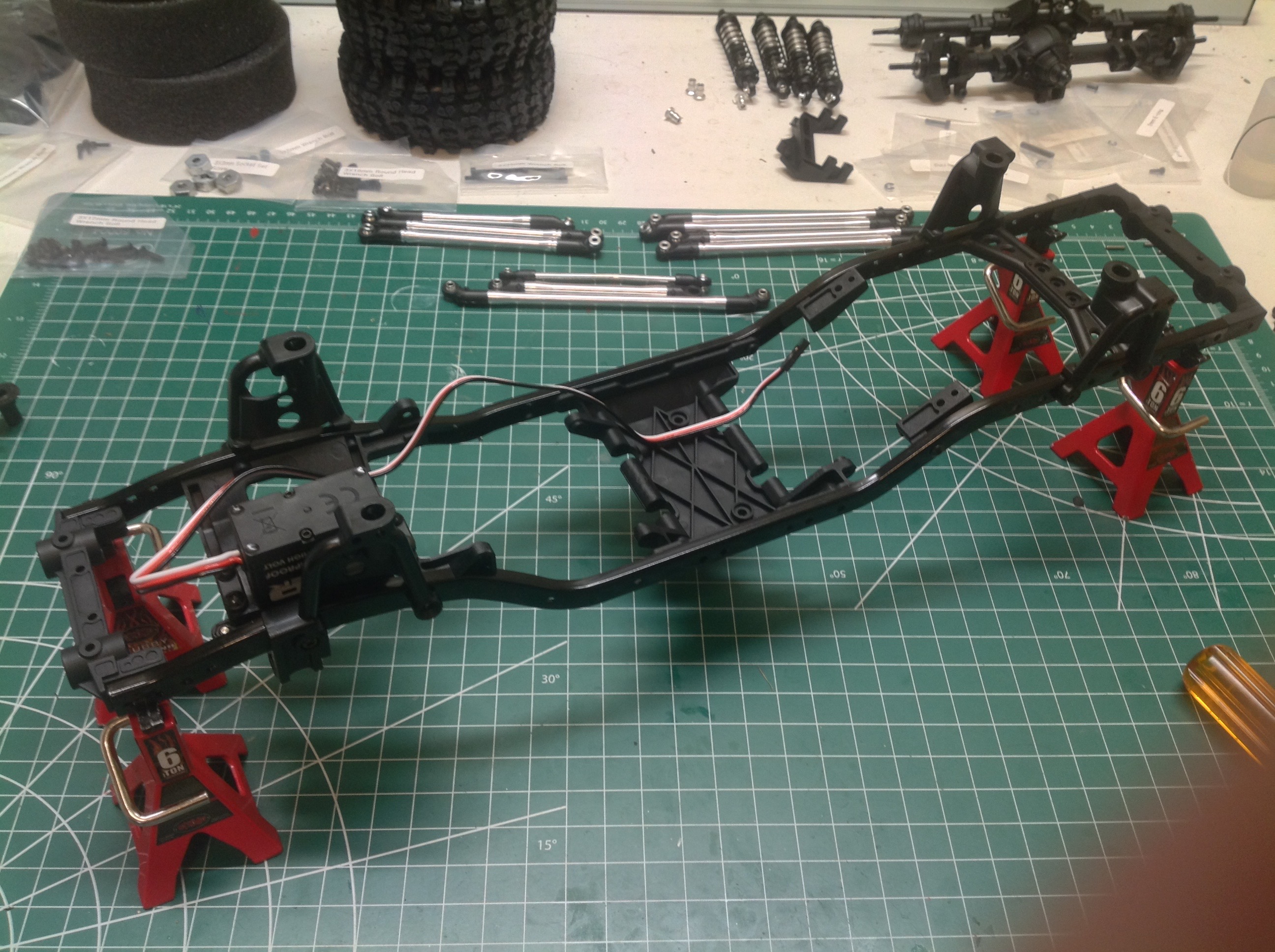
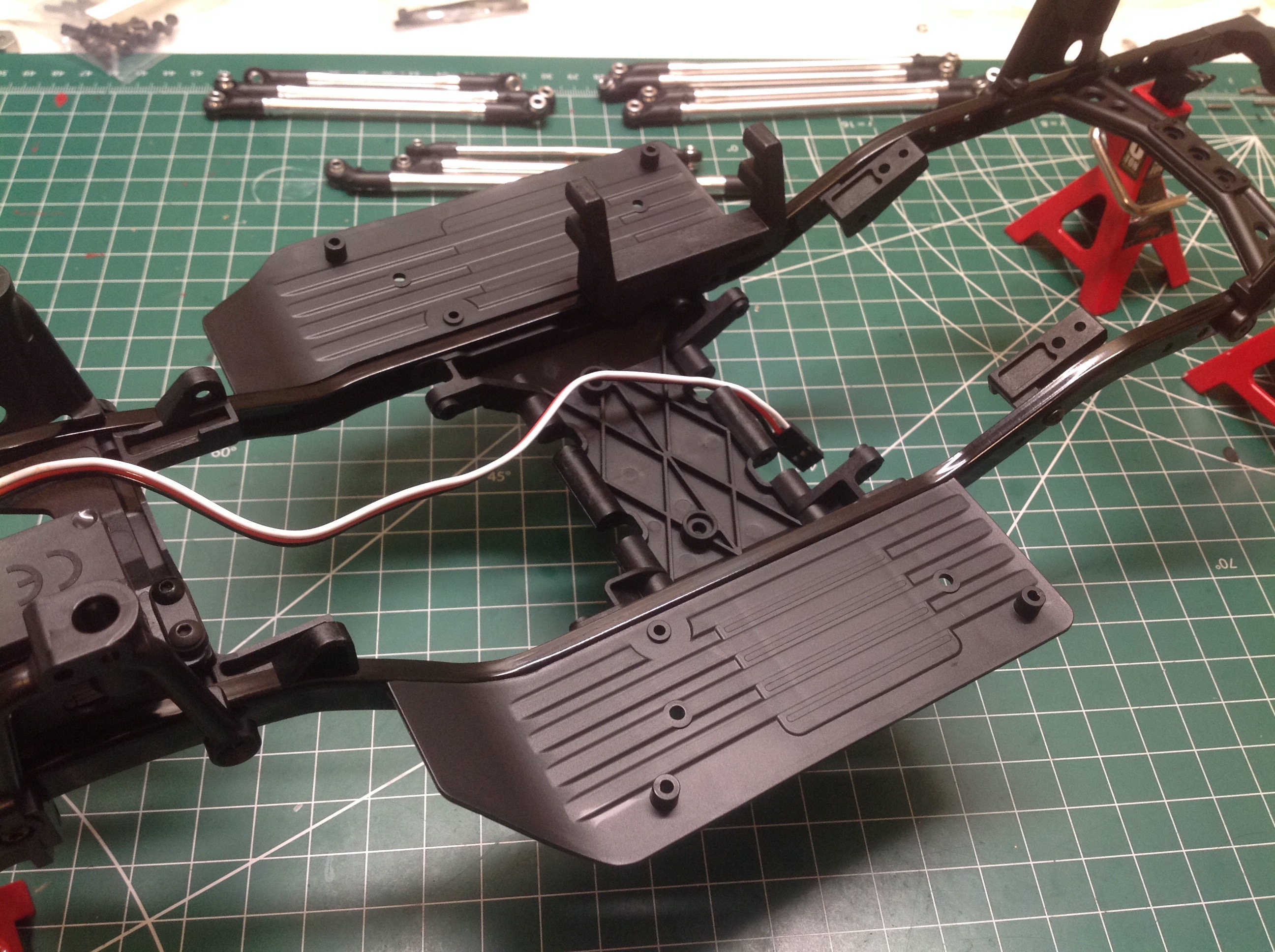
Now the frame can be assembled starting with the formed metal rails and
plastic cross members as shown on the left. The shock hoops are
also installed at this point. On the right you can see the ridge
floorboards which provide a lot of space for electronics.
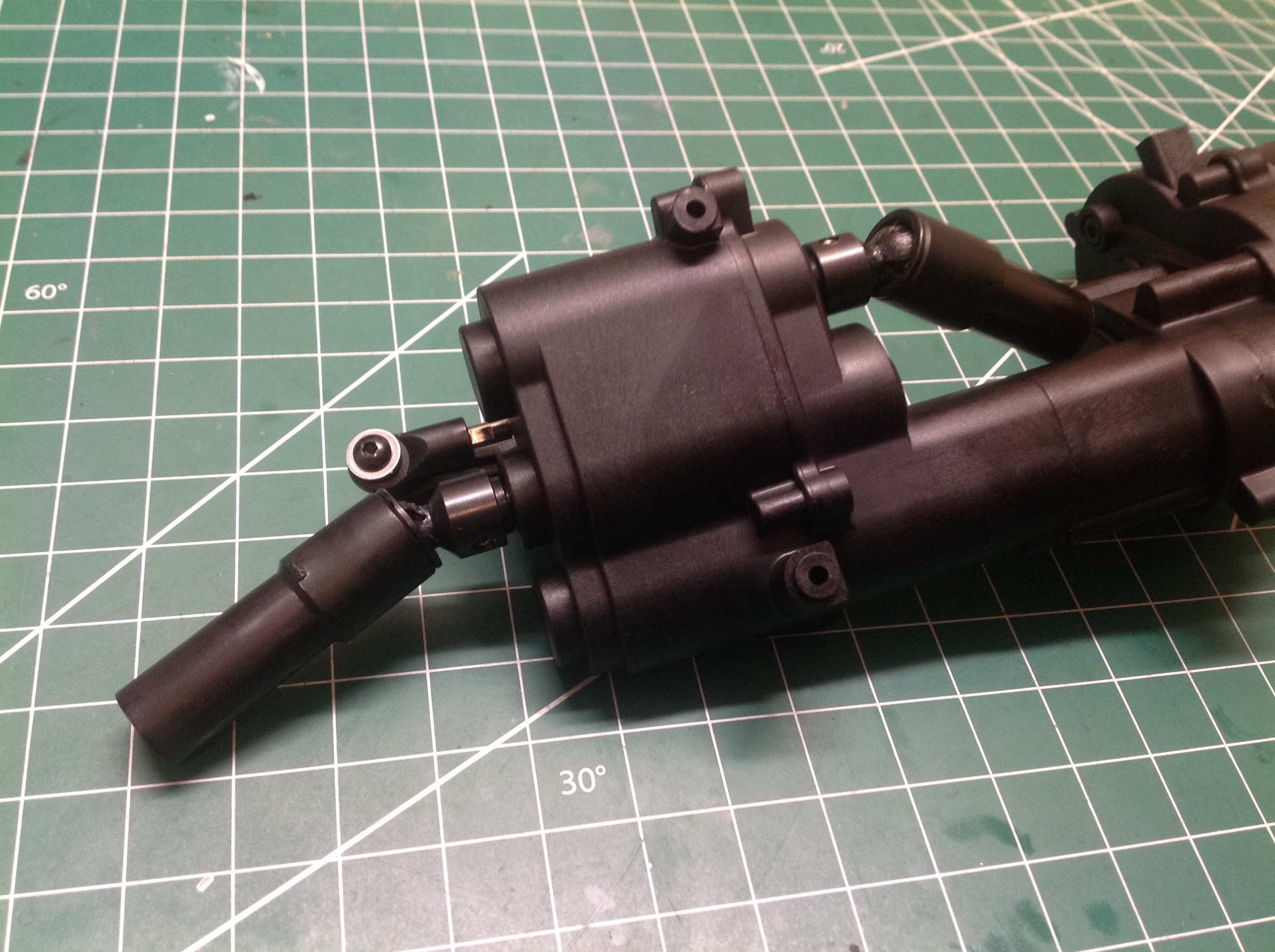
The drive shafts must be assembled manually. The CVD ends are
metal which are connected to plastic internally splined shafts. On
the left you can see one end of the shafts connected to the axles while
the other ends are connected to the transmission as shown on the right.
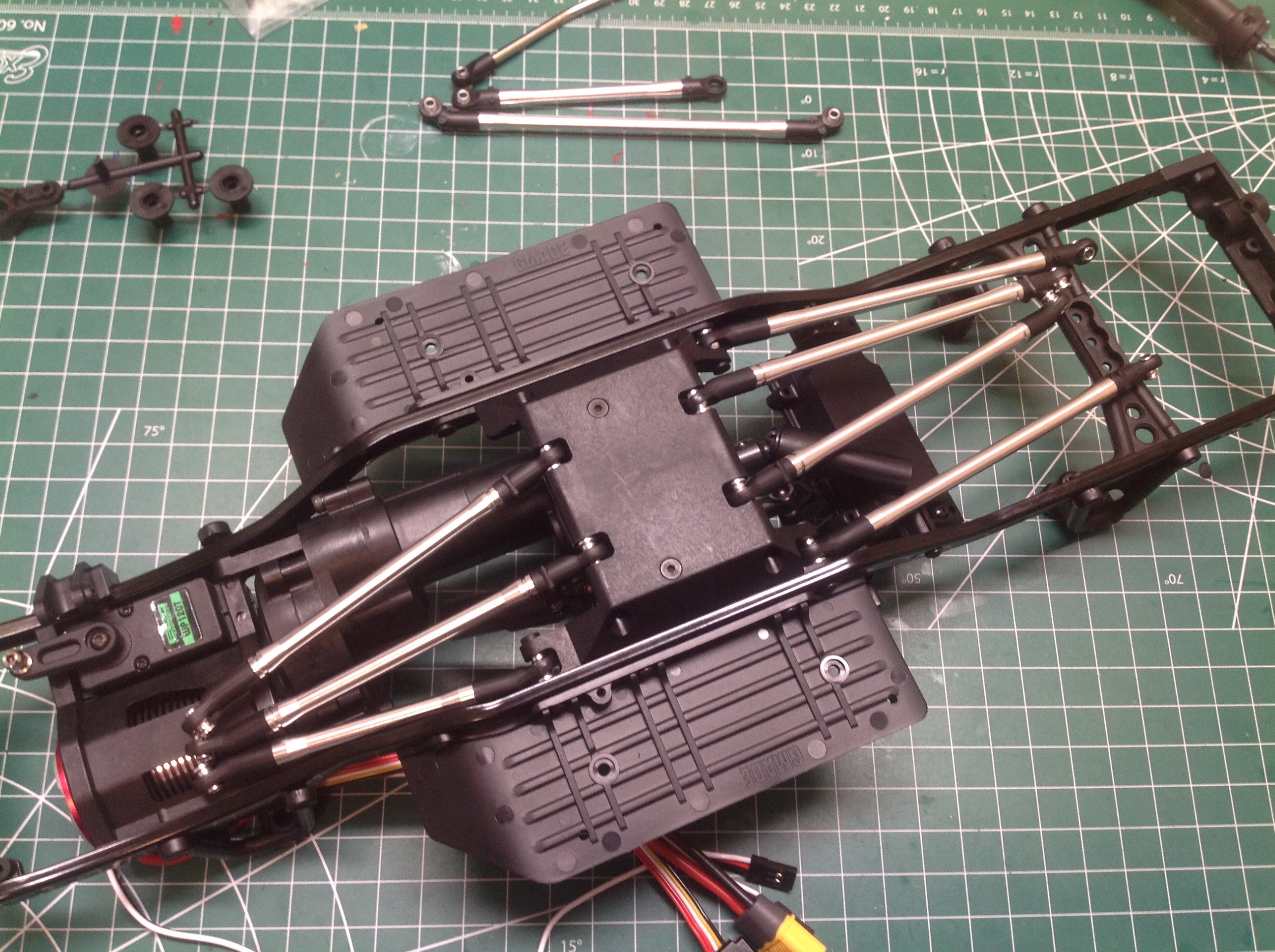
Now the transmission is bolted onto the skid plate and balanced at the
front of the chassis as shown on the left. On the right you can
see the links attached to the inverted chassis. Note the smooth
bottom to the skid plate. Note also the the rear suspension has
four links while the front has three. The box you see near the
back is intended for the radio, but I ended up moving this forward
later.
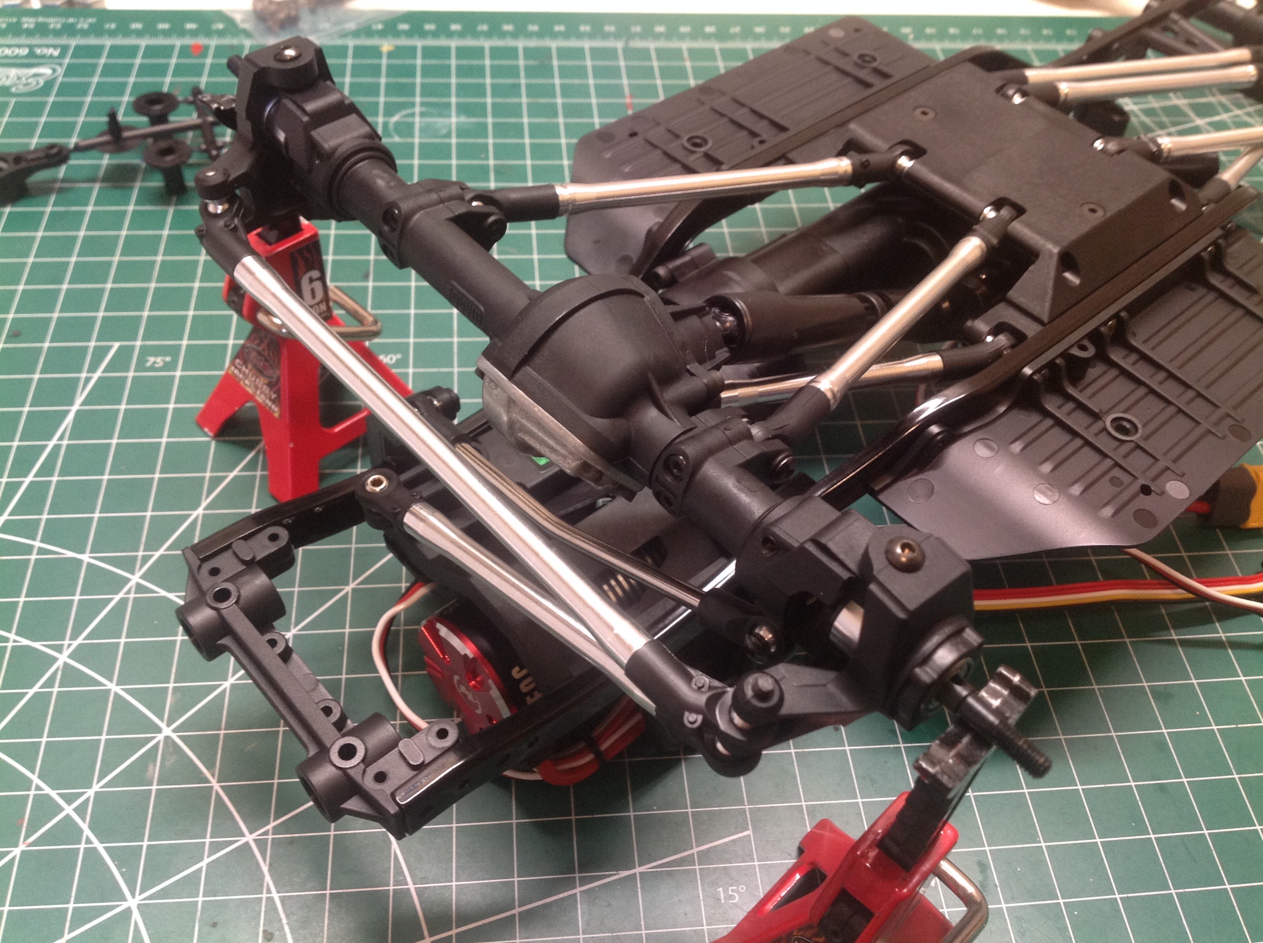
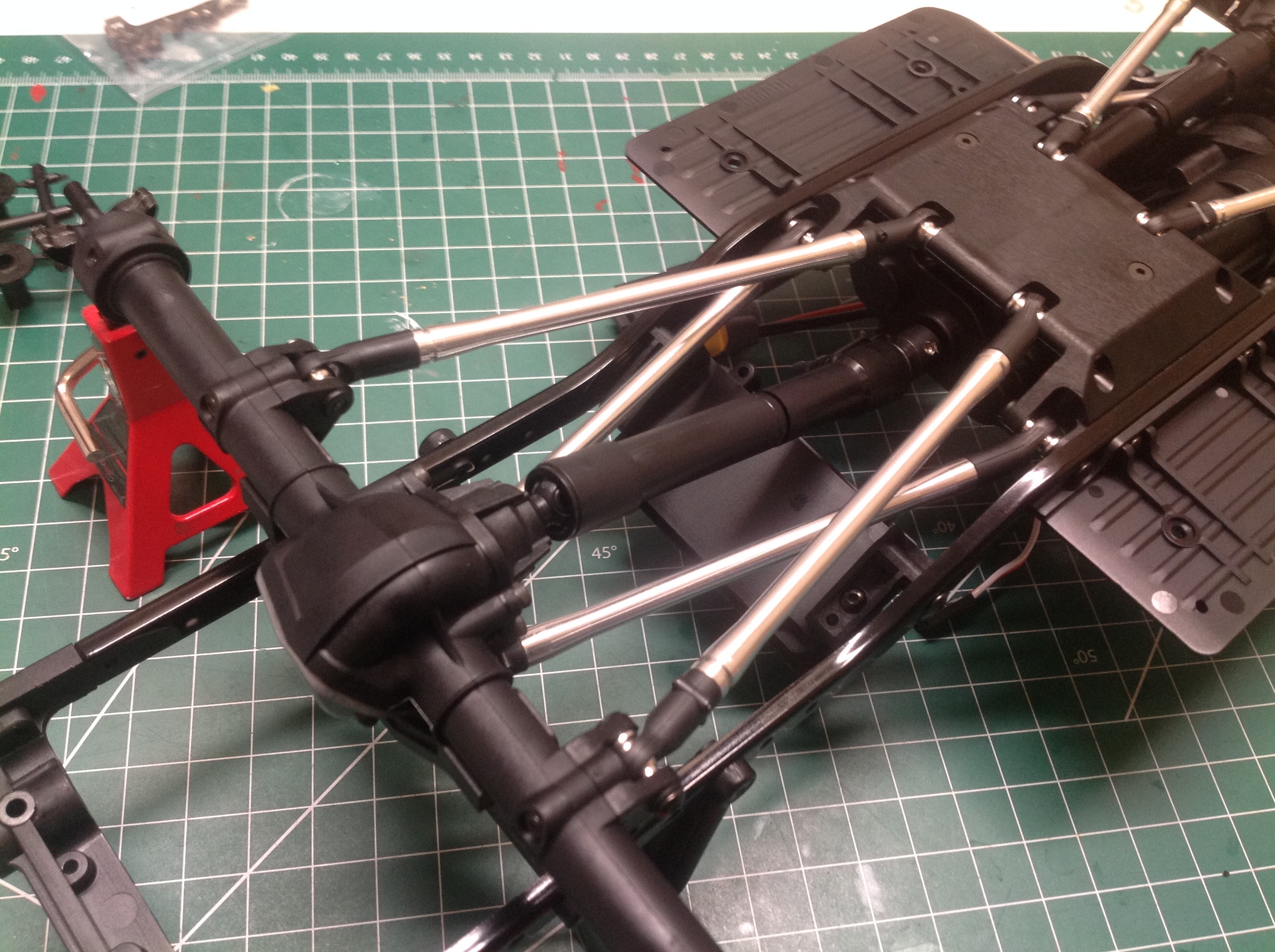
Here we can see how the axles are attached from bottom views. The
left hand image shows the front axle including the panhard bar.
The somewhat hidden kinked bar is the steering link. The right
hand image shows the simpler rear suspension.
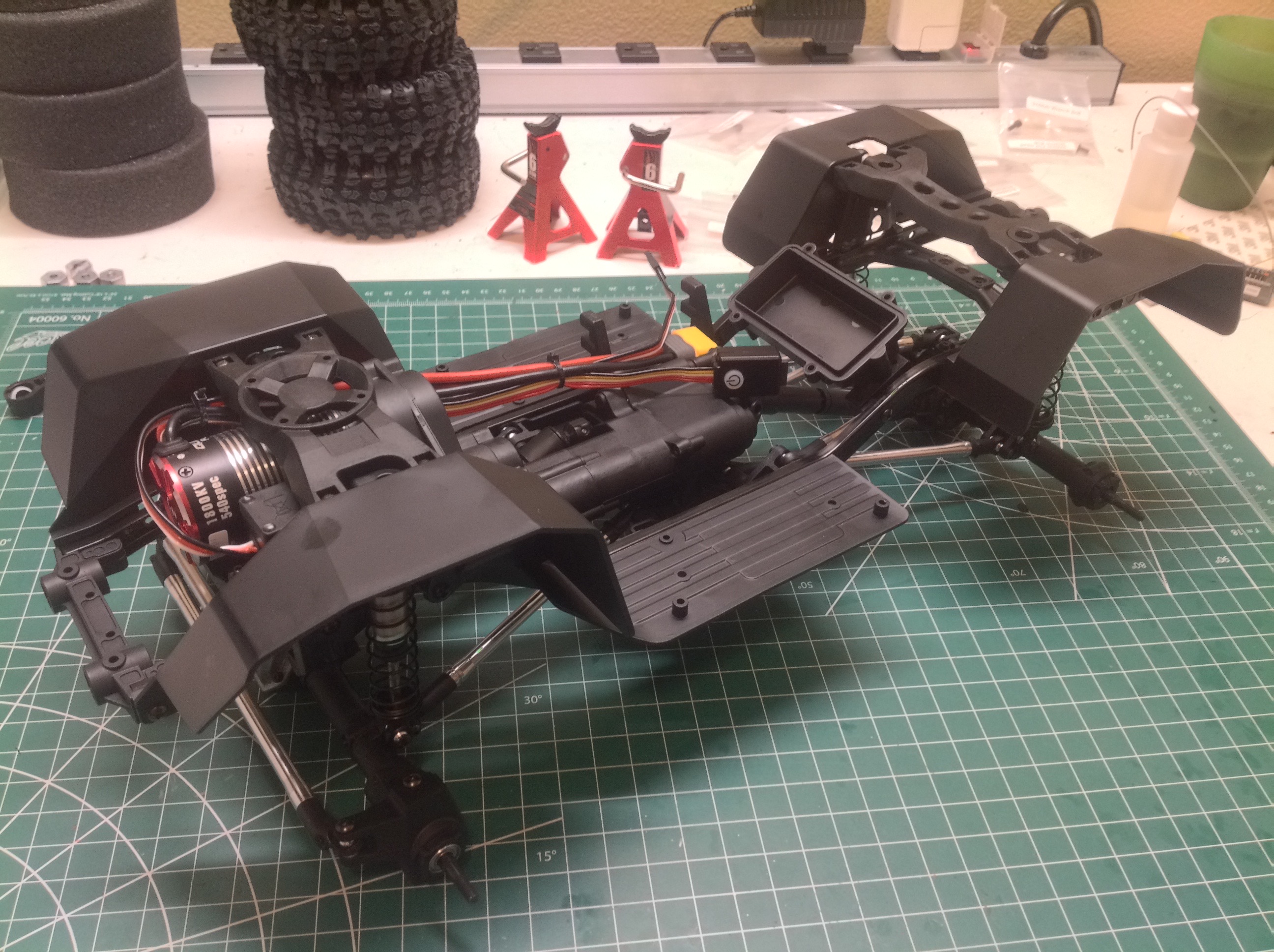
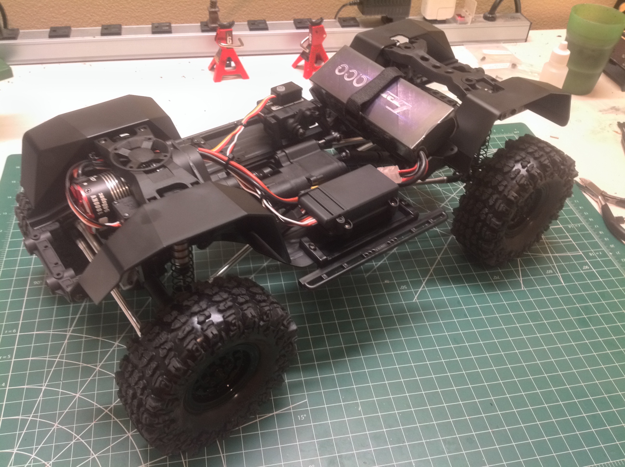
Attaching the shocks completes the suspension. After that the
inner fenders can be installed which are nice molded parts that really
fill out the chassis. There are also upper cross members that span
the fenders and serve to stiffen the shock supports. The front
cross member has a faux fan, but a real fan could be attached here to
cool the motor. On the right you can see the installation of the
shifting servo.
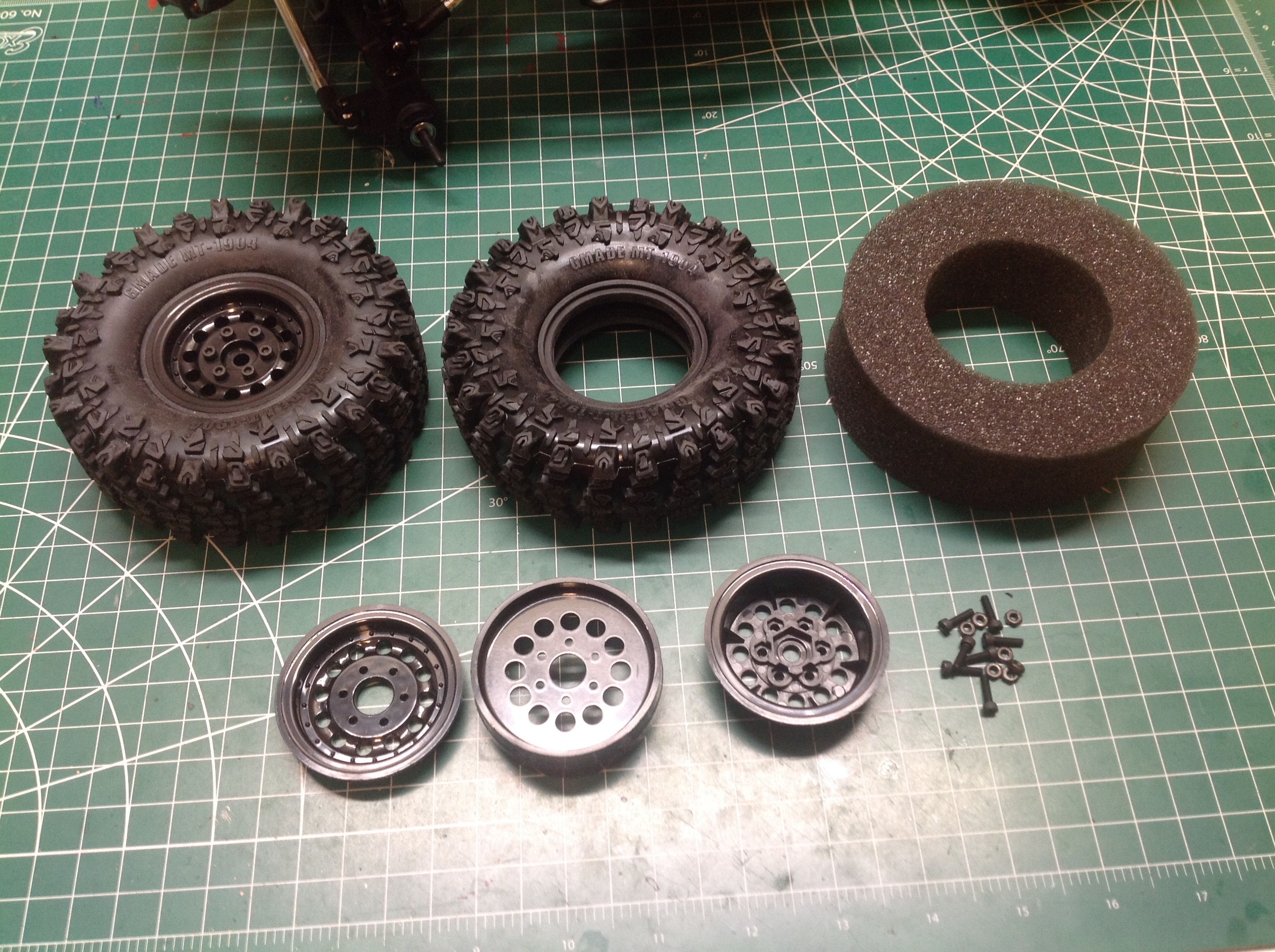
The wheels might be plastic, but they are good looking beadlocks and the
tires are nice and soft. They went together easily. The
right hand image shows the completed rolling chassis. Note that
I've moved the radio box forward and put the battery crosswise in the
rear. The battery can optionally be installed across the
transmission, but I wanted it further back to leave room for a future
interior.
©2021 Eric Albrecht