Tamiya F-350 Highlift Project
Page 2: Installing the MFC
The MFC-02 Multi-Function Control Unit is an electronic system which
adds sounds, lights, and vibration to any of the High Lift truck
kits. It is very similar in principle to the MFC-01 system for
1/14 scale tractor trucks, but with slightly different features and
sounds targeted at pick-up trucks. The system takes the place of
an ESC and includes 21 lights, a vibration motor unit, a speaker, a
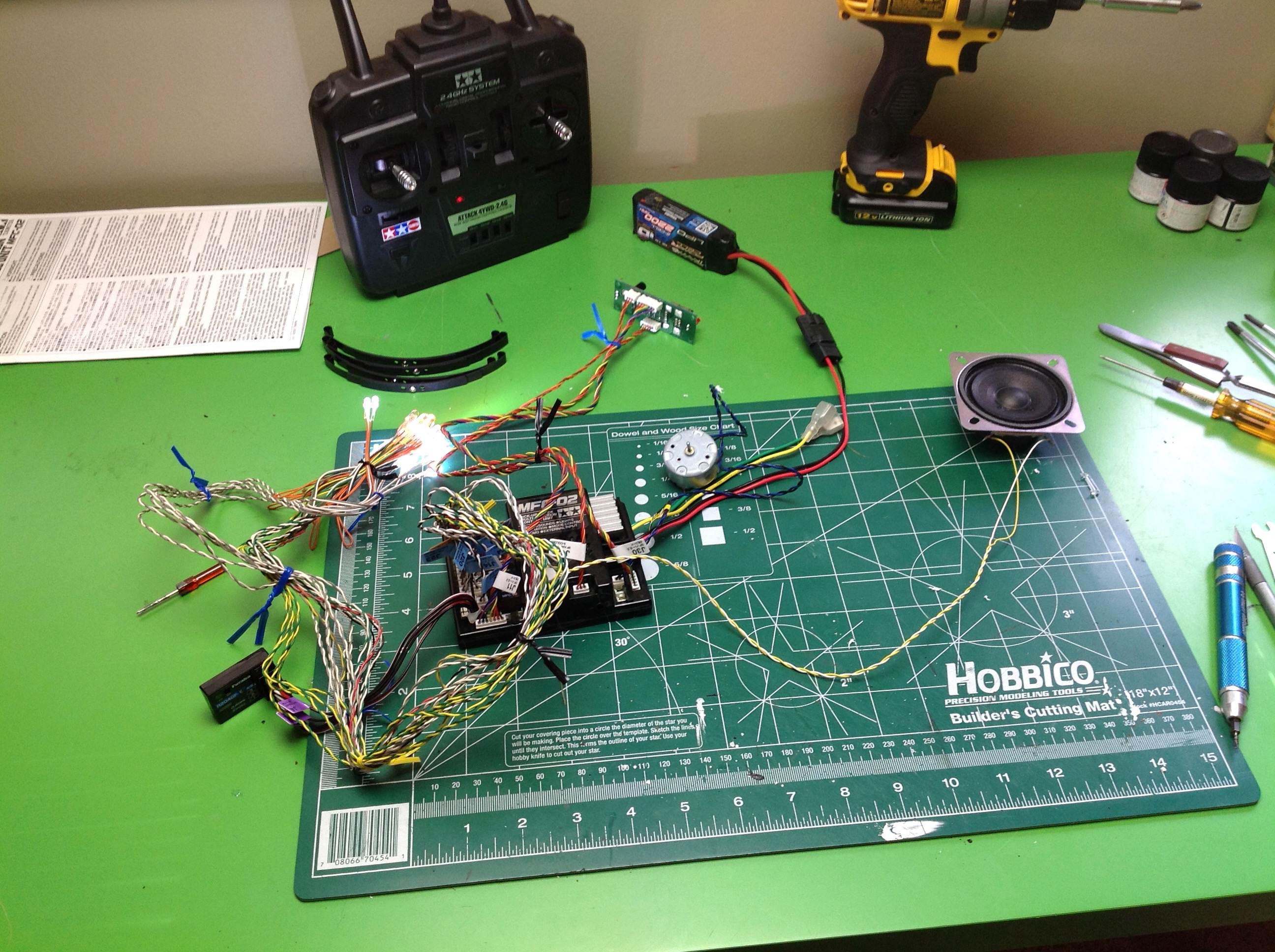
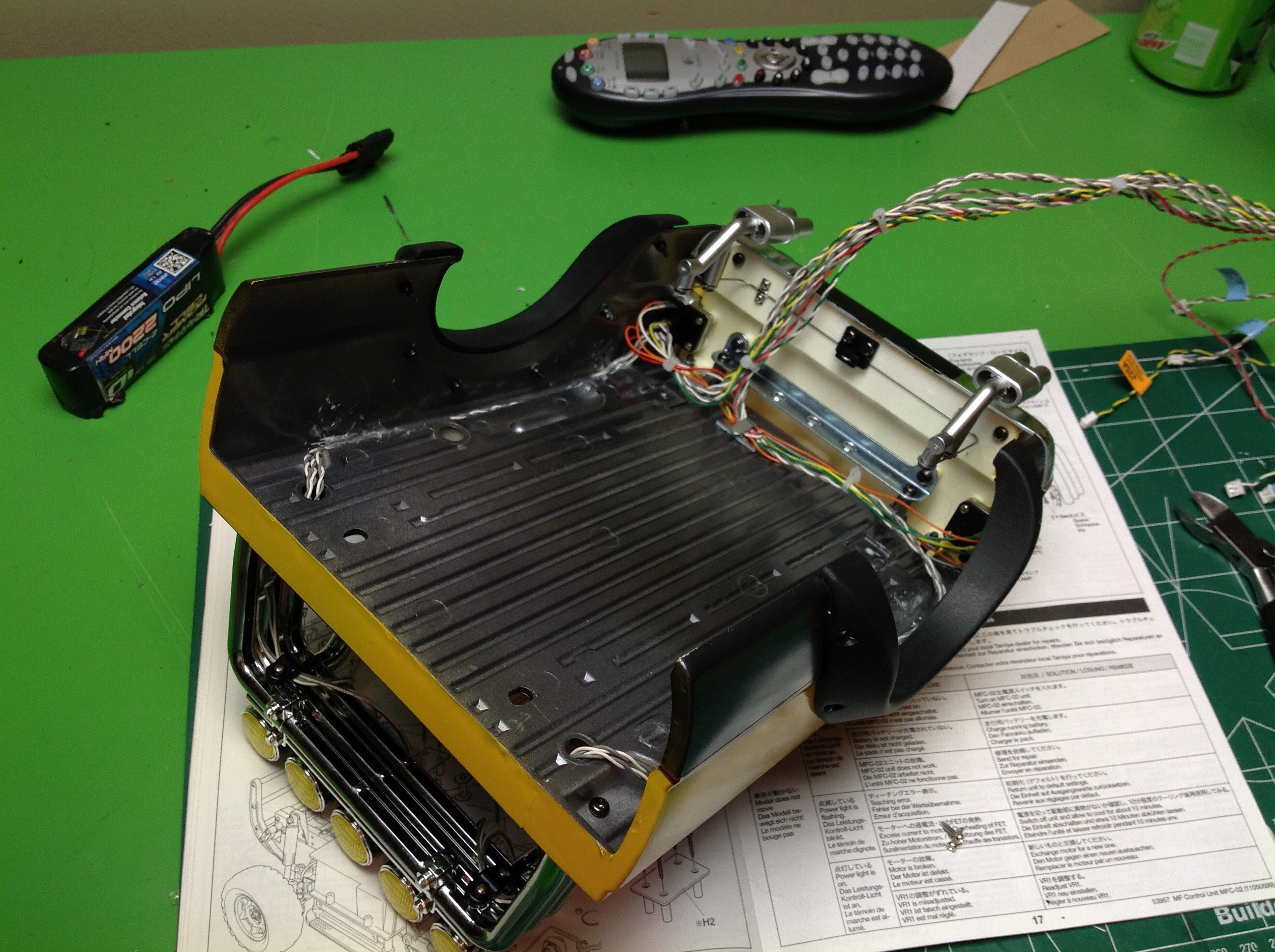
control unit, and a control panel. The first picture shows
everything hooked up for testing. It looks like quite a mess and
it is hard to imagine how it would all fit, but when cleaned up it is
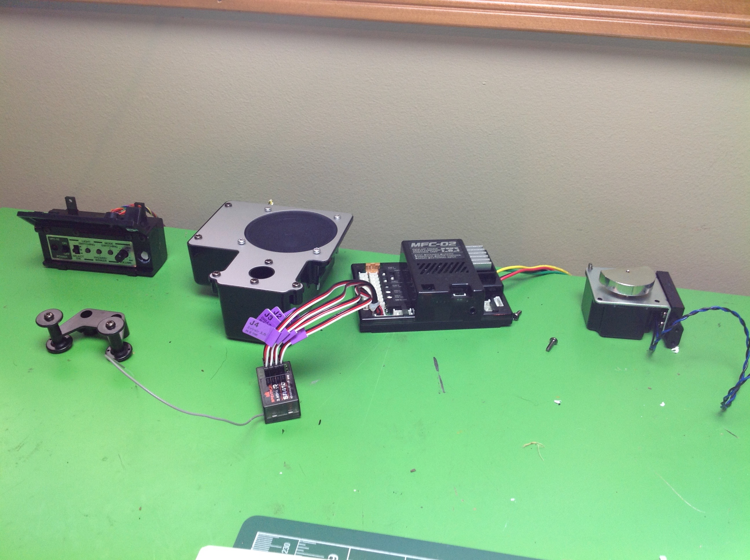
not so bad. The picture on the right shows the built enclosures
for the control panel, speaker, control unit, and vibration motor (left
to right). In the front row are a post tower for bundling the
wires and a 4 channel receiver. All of the plastic bits for these
boxes are included in the MFC kit along with the electronics. 4
receiver
channels must be connected to the control unit, then the steering and
shifting servos can be attached to it as well. You must supply
your own 4 channel receiver. You can drive the truck with only 3
channels, but you can't access all the MFC functions.
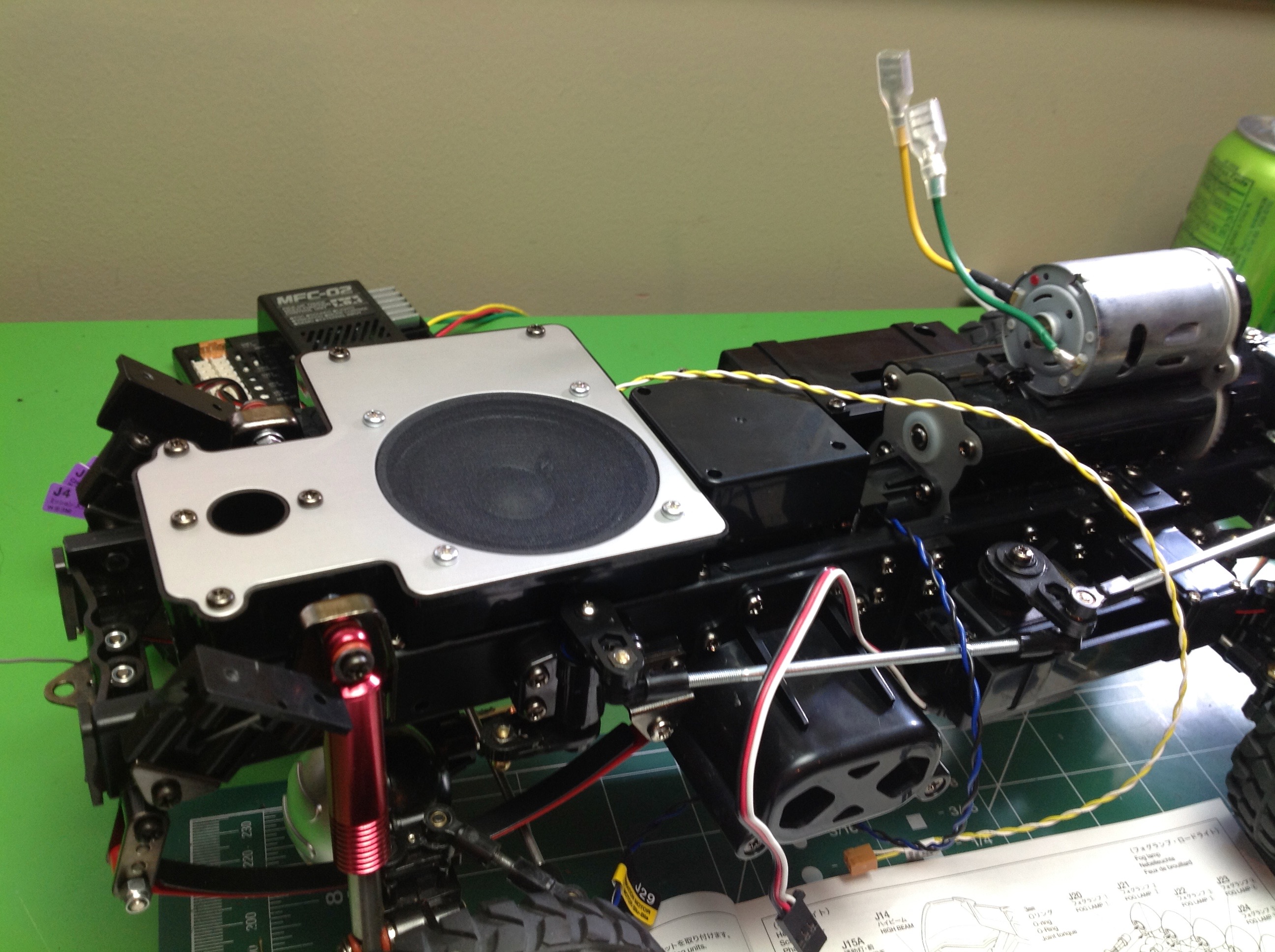
The speaker unit sits in the back between the frame rails and under the
bed. The kit is already provisioned for it so it is very easy to
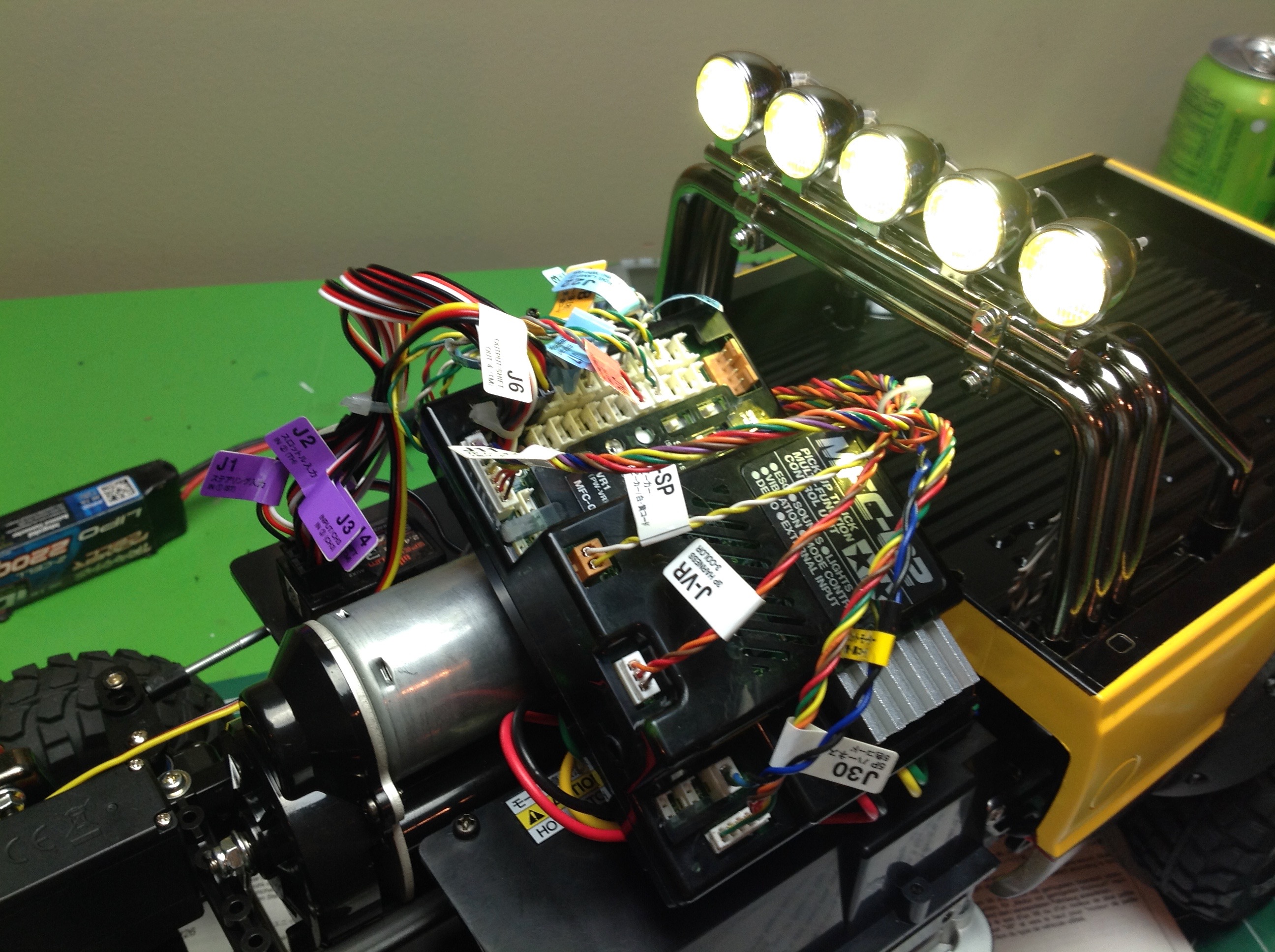
install. Immediately ahead of that goes the box for the vibration
motor which works by spinning a small offset weight. The MFC
itself sits in the cab, but that space is already occupied by the motor
so it needs to be mounted on a bracket at an angle (right image).
There is still
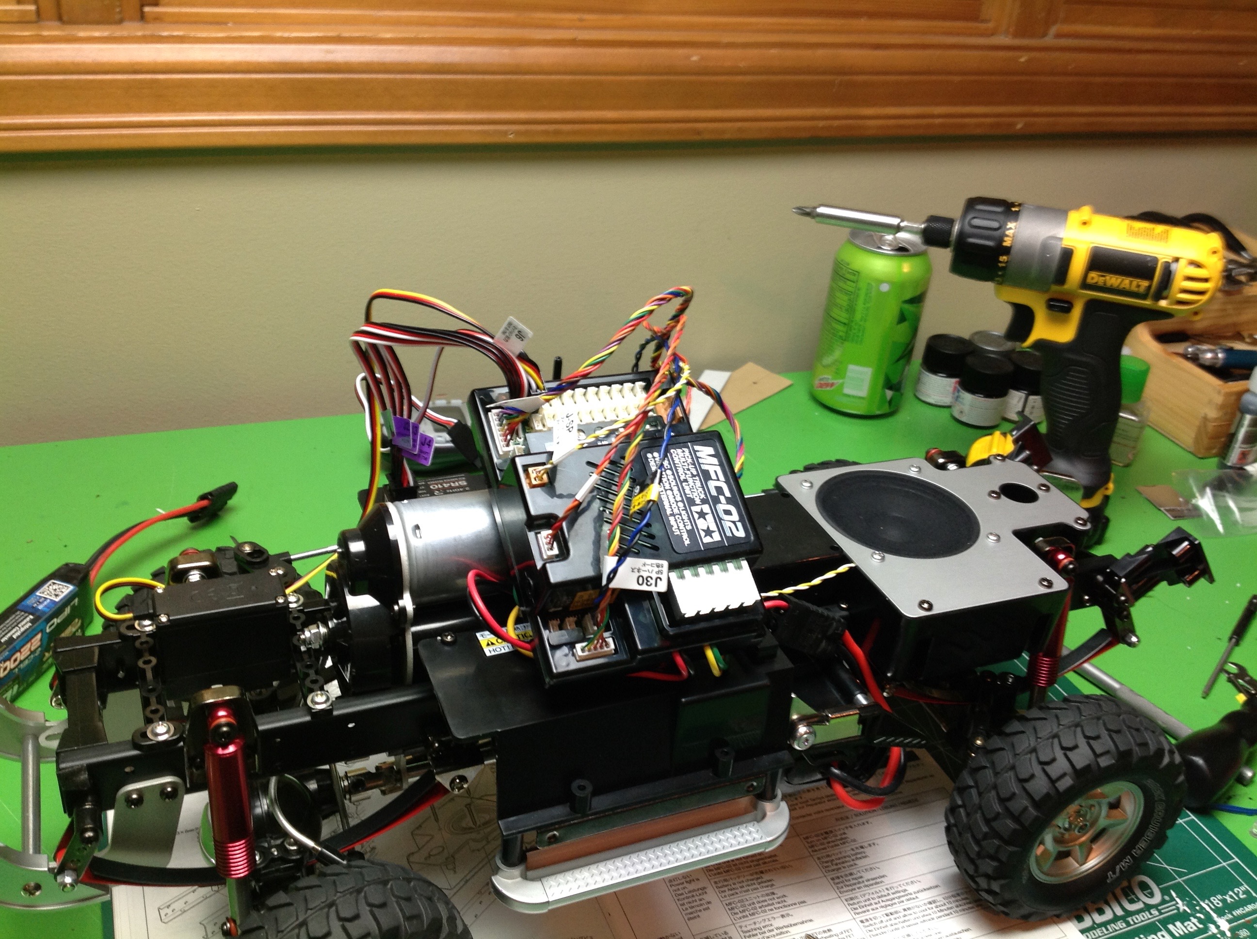
plenty of room for the receiver. The control panel fits in the
box under the MFC and above the running board on the left side. It
can be easily accessed from below even with the body on. At this
point all the control wires are installed and only light wires remain.
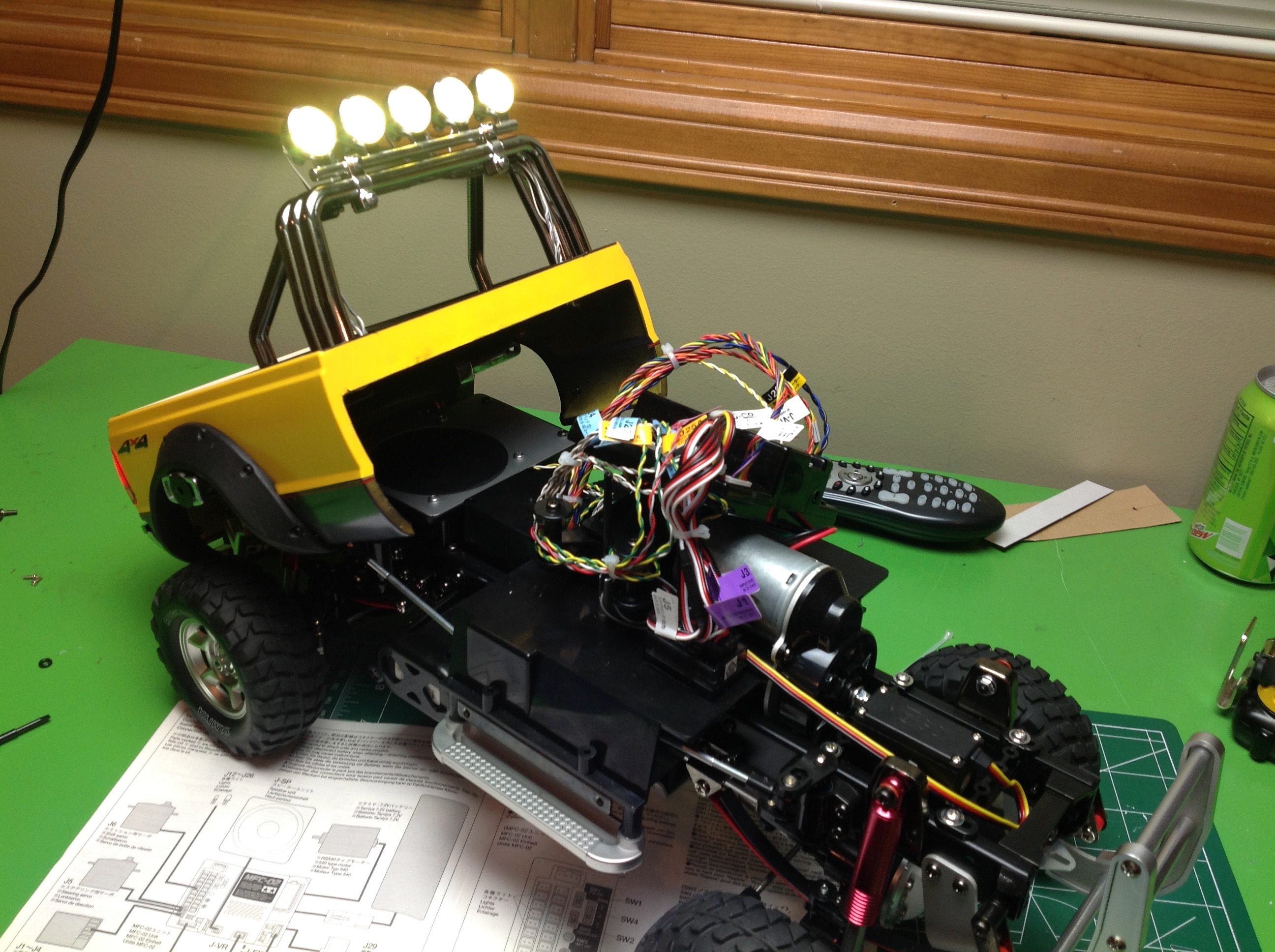
Now all of the lights need to be mounted. There are 5 lights on
the roll bar. Each of them has its own circuit because they can do
interesting sequential patterns in demo mode. In regular mode,
they all light up together. The LEDs are white but the lenses are
yellow. The tail lights consists of a red brake light, an amber
turn signal, and a white reverse light on each side. The wires all
need to be routed to the back so they do not pull when the bed is
hinged open for battery access. You can also see how the exhaust
pipes hang down from wires so that they shake when the vibration motor
is turning.
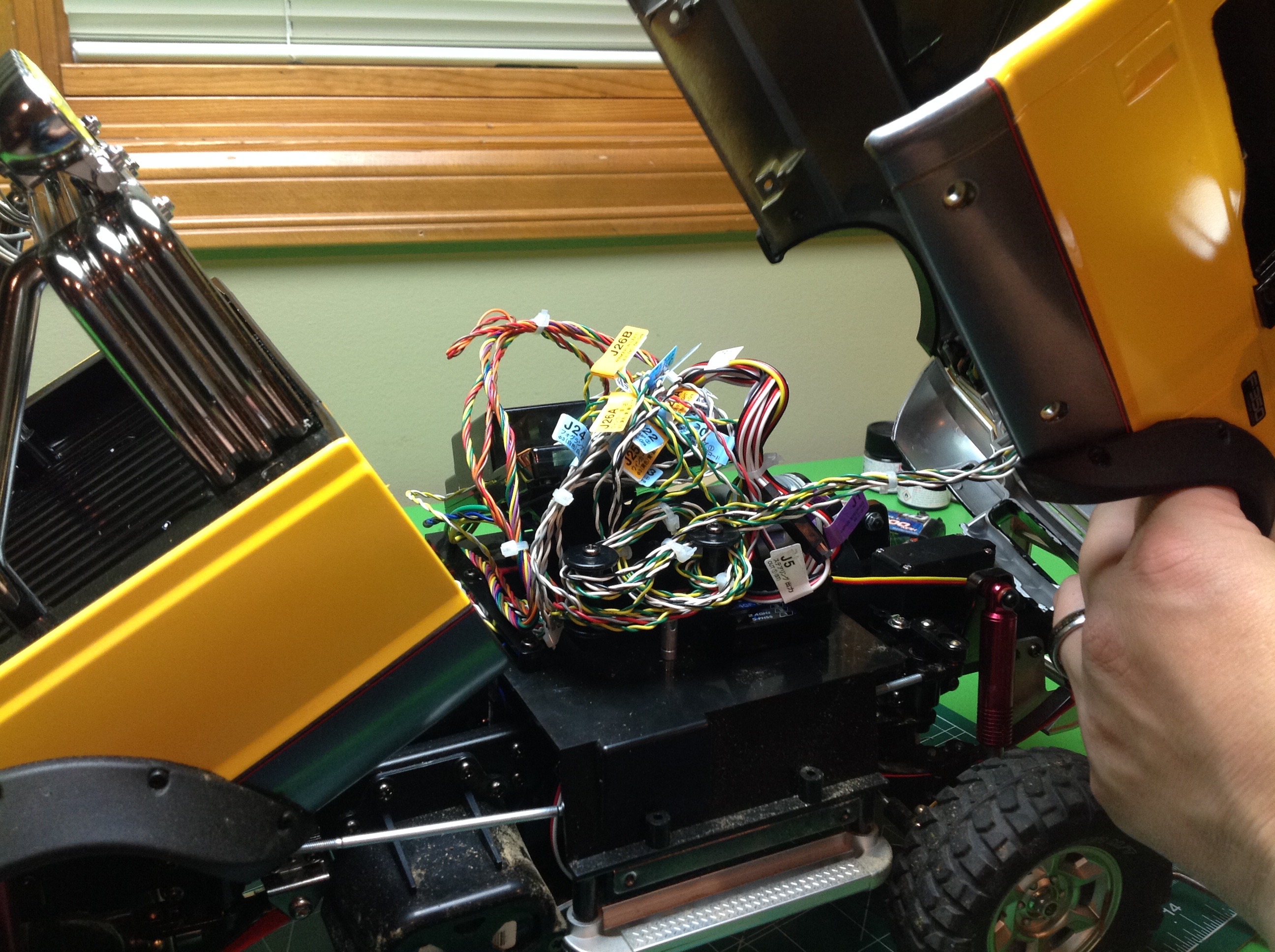
Once the bed is attached to the vehicle I routed the wires to the
MFC. I tried to run them behind and under the speaker so they
would not tangle on anything when the bed opened, and also so they would
be protected from obstacles. Plugging them into the MFC is an
easy matter if you remembered to label them all with the included
stickers. Just follow the diagram in the instructions to see where everything goes.
The front of the body has headlights, passing lights, marker lights, and
turn signals on each side. The right photo shows everything
connected. The extra wires wrap around a set of posts to get out
of the way. Once the front is screwed on, you shouldn't need to
open it again.
The F-350 uses 19 lights which is not everything that comes with the
kit. The lighting configuration on the Toyota kits is slightly
different with fog lights on the bumper. The instructions also
indicate that there are features which support a number of "games", but
there is no information on what these games are and I found nothing on
the Internet either. I guess this was an optional future feature
that they never released. There are several demo modes which run
through all the features without any user input, and some include some
really mesmerizing light effects including "Knight Rider" type
sequential movement of the fog lights.
©2017 Eric Albrecht