Capo JK Max Project
Page 1: Building the Engine
I have rarely been so excited waiting for a package to show up.
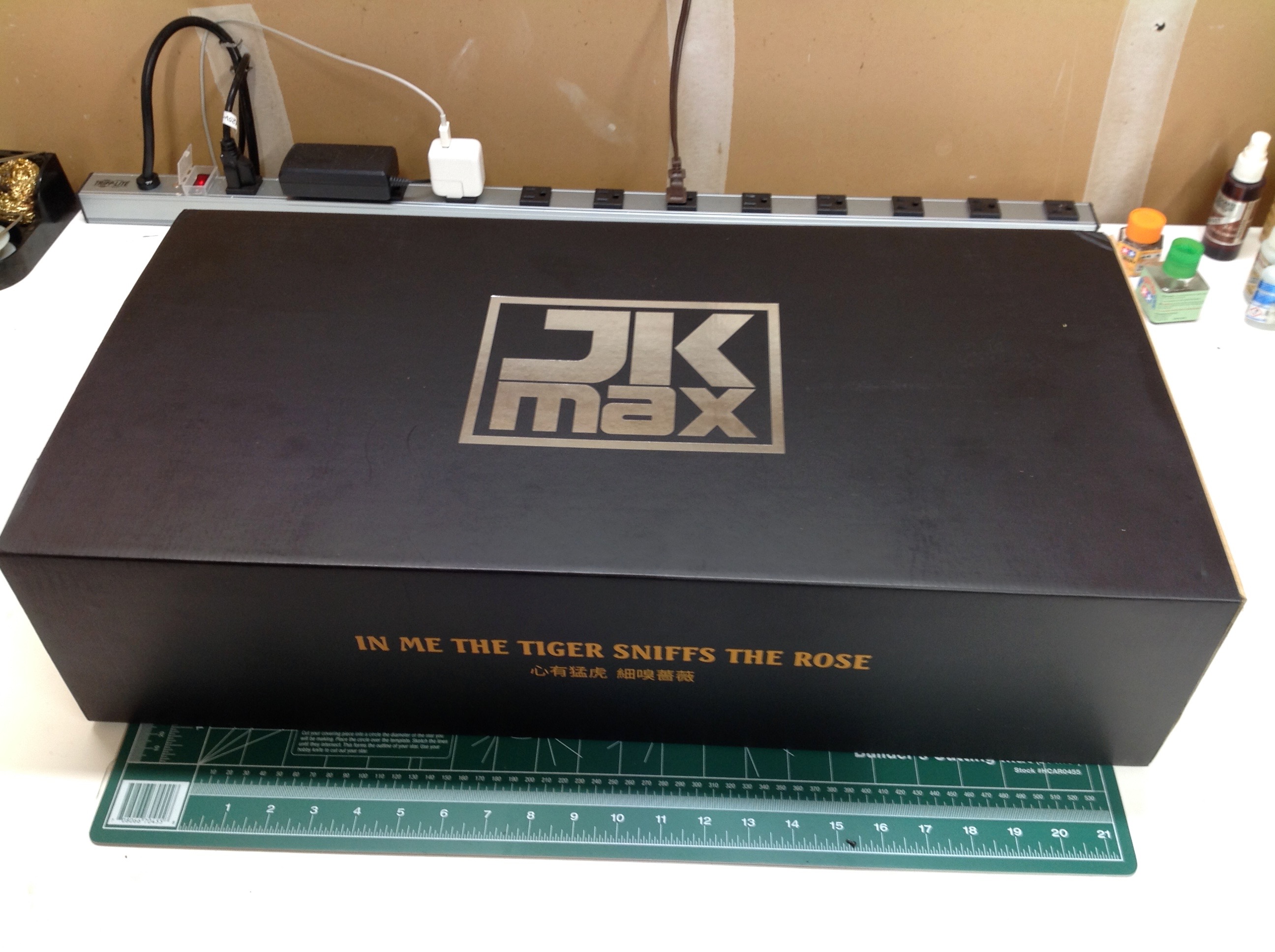
The box is actually smaller than you'd expect and there are no pictures
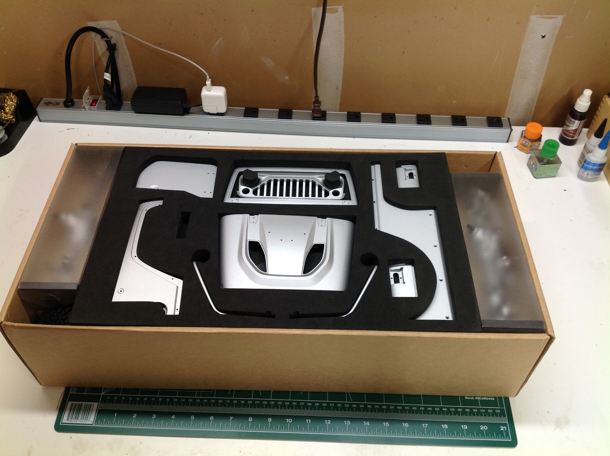
on the outside to tell you what's inside. Once you open the box
you are greeted by a foam insert laying out all the primary metal body
panels with the prebuilt axles to either side. Beneath the foam is
a smaller box containing all the piece parts. The small empty
slot you see in the foam is where the USB flash drive was which contains
the video instructions.
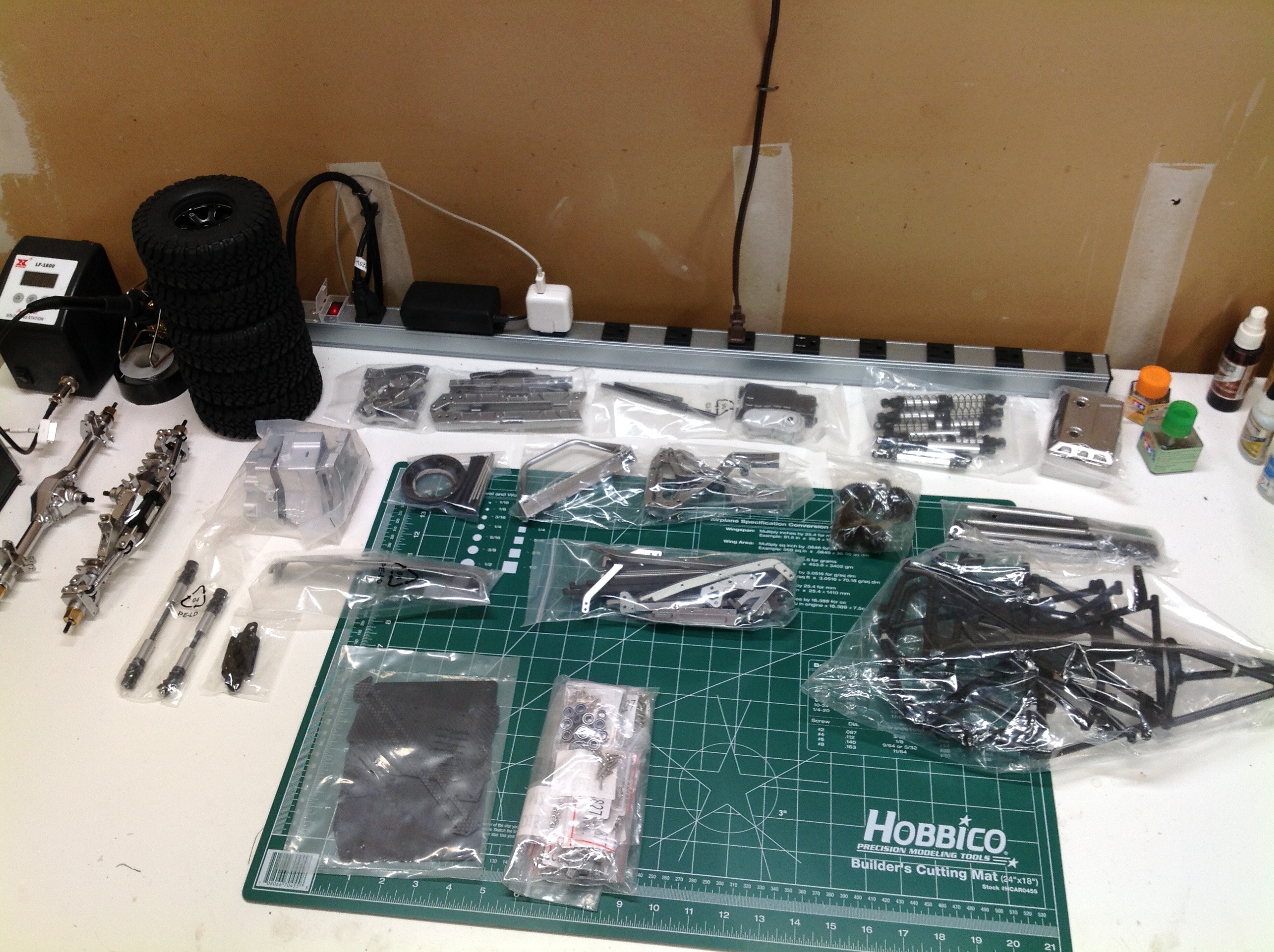
Here is everything that was under the foam. There are 5 tires
(including the spare) and many bags of metal parts. There are only
a couple of plastic parts trees. In the right hand image you can
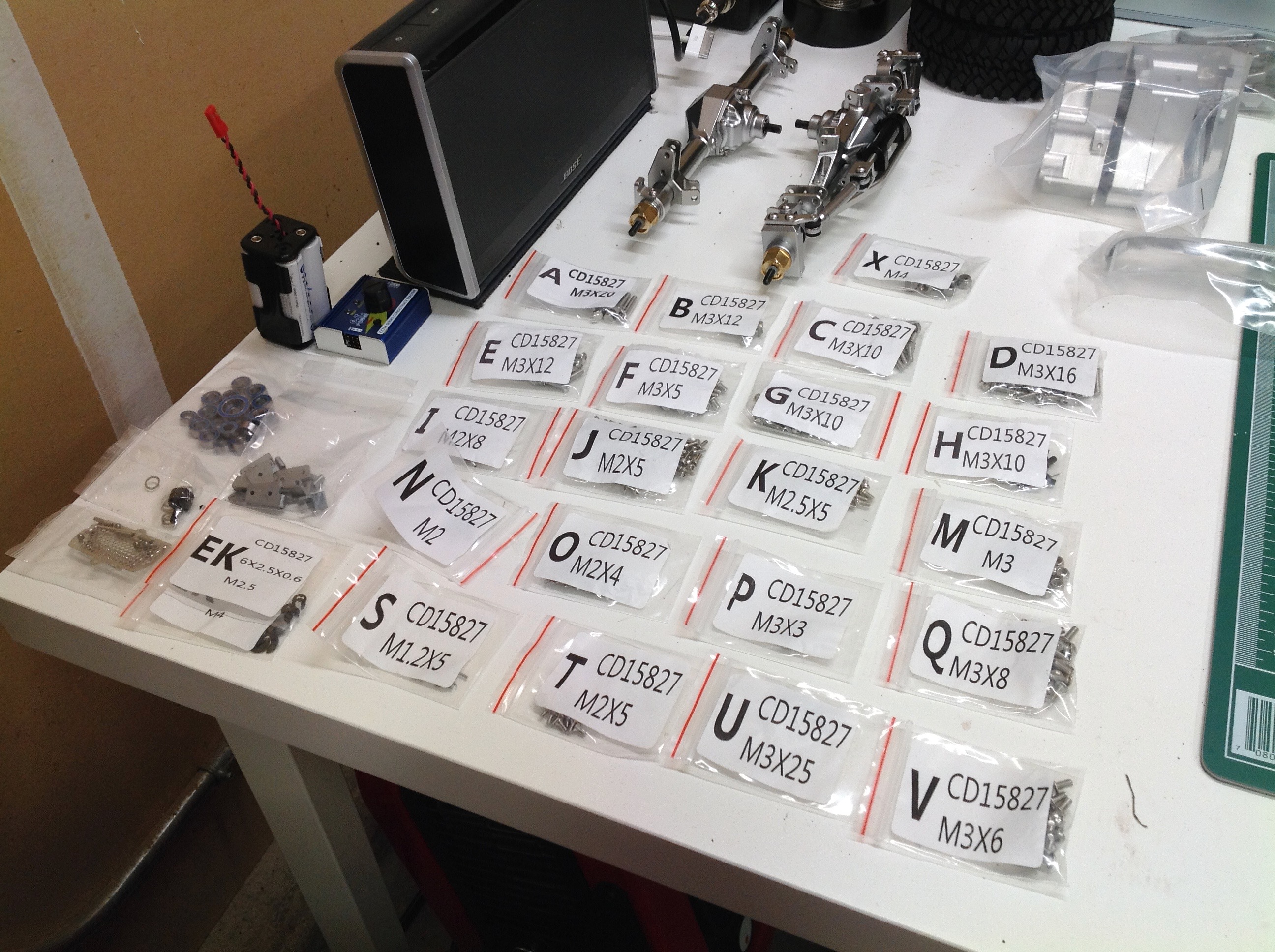
see the large number of individually bagged hardware types.
Everything appears to be stainless which is good for threading into
aluminum. Since nearly every screw and bolt threads into metal, it
is really important to use thread lock everywhere or this thing will
just fall apart.
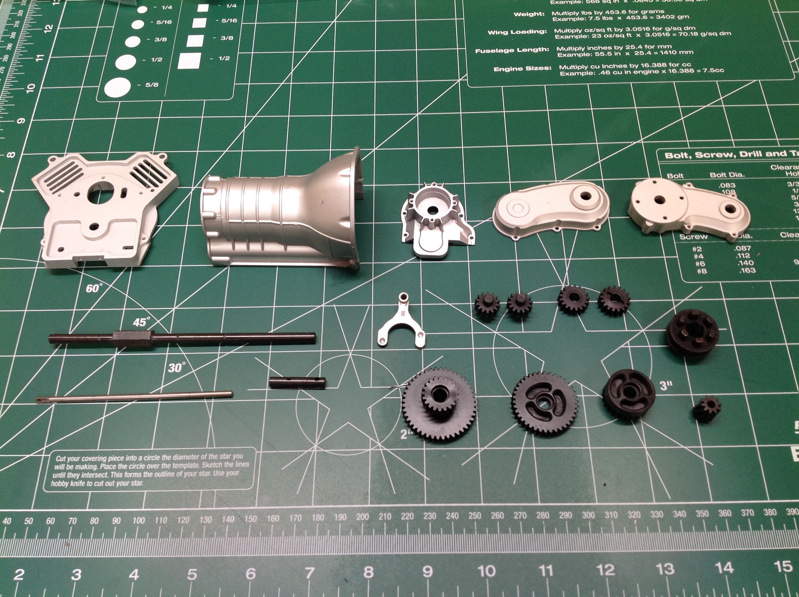
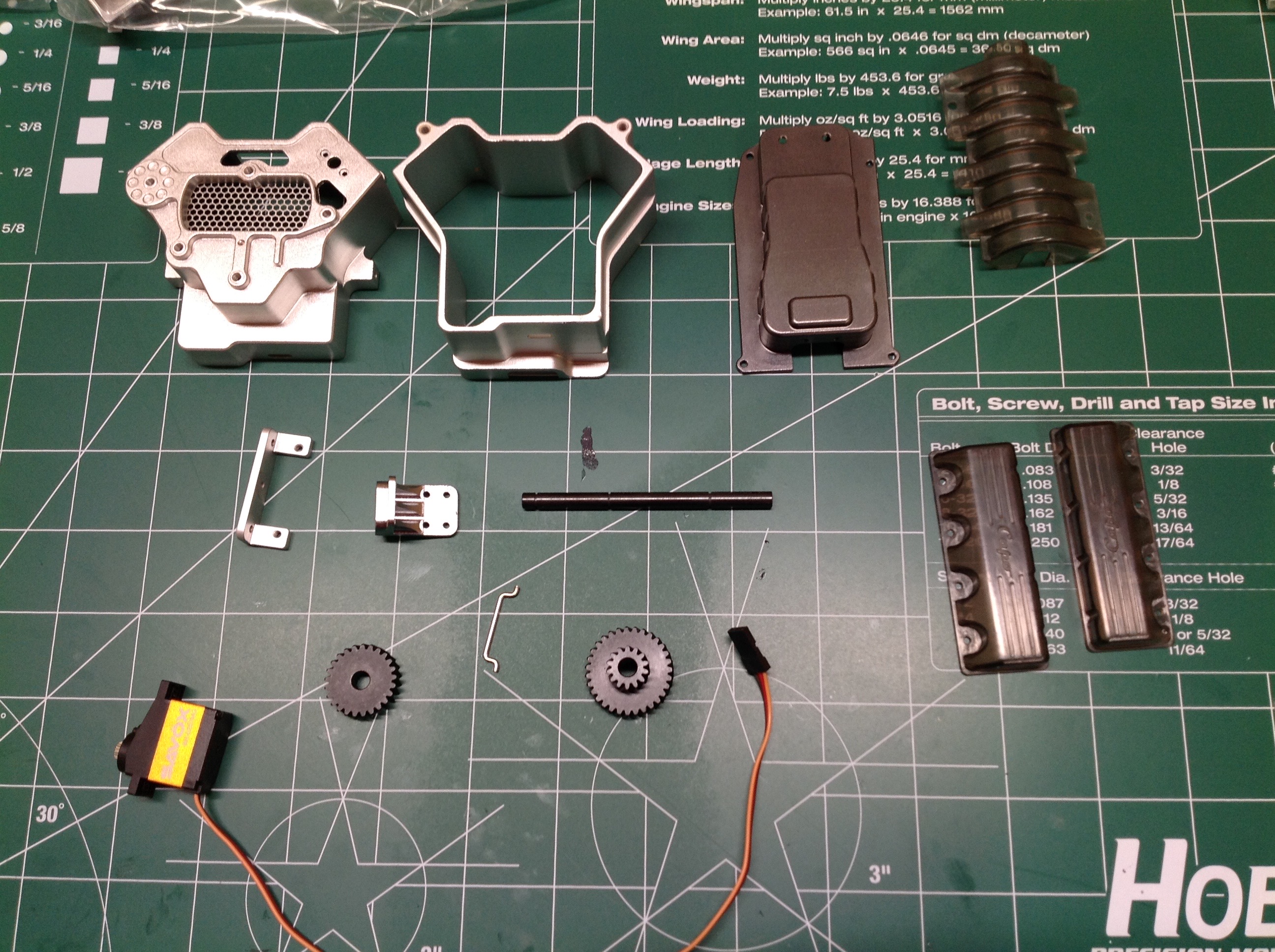
Here are the parts laid out for Step 1 which involves starting the
construction of the 2-speed transmission. Everything you see is
metal. The bell housing and transfer case housings appear to be
cast aluminum. The shafts and gears are steel. The
transmission gears are all helical. This includes the pinion gear
which you can see on the right. I've never seen a helical pinion
before. Capo's marketing material indicates that mating gear pairs
are made from different types of steel. This is exactly how it is
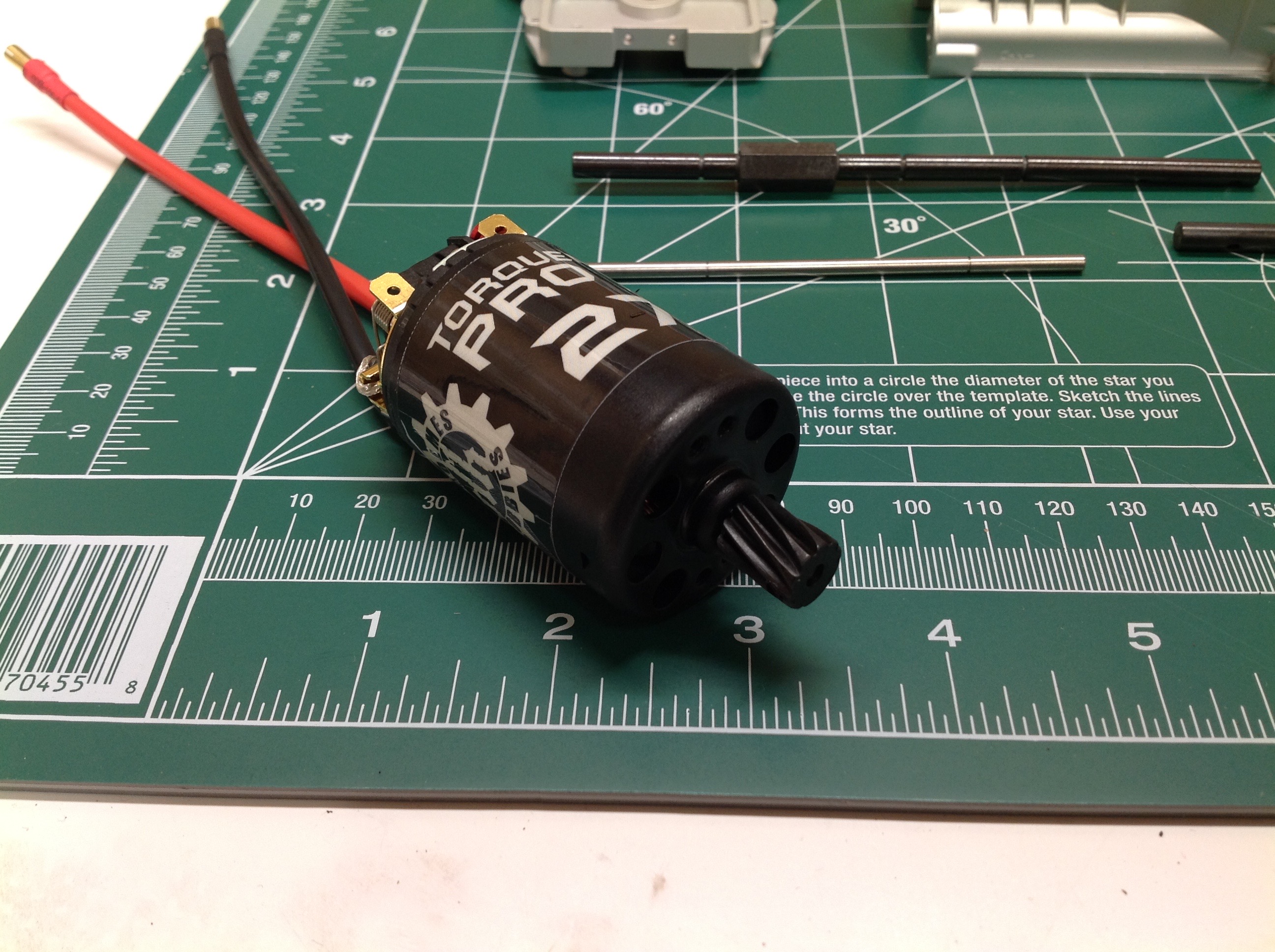
done in industry to prevent too much tooth wear. I chose a Holmes
Hobbies brushed motor which has really showed me how good it is
possible for a brushed motor to be. For trail trucks and crawlers,
I still prefer brushed over brushless for the feel. Even sensored
motors don't come close.
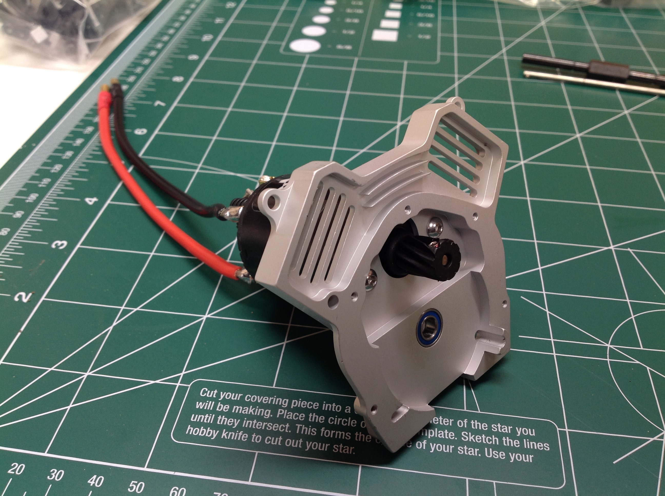
The motor is installed to the rear cover of the engine block. The
front cover has a mesh screen to allow airflow through the otherwise
closed block for cooling the motor.
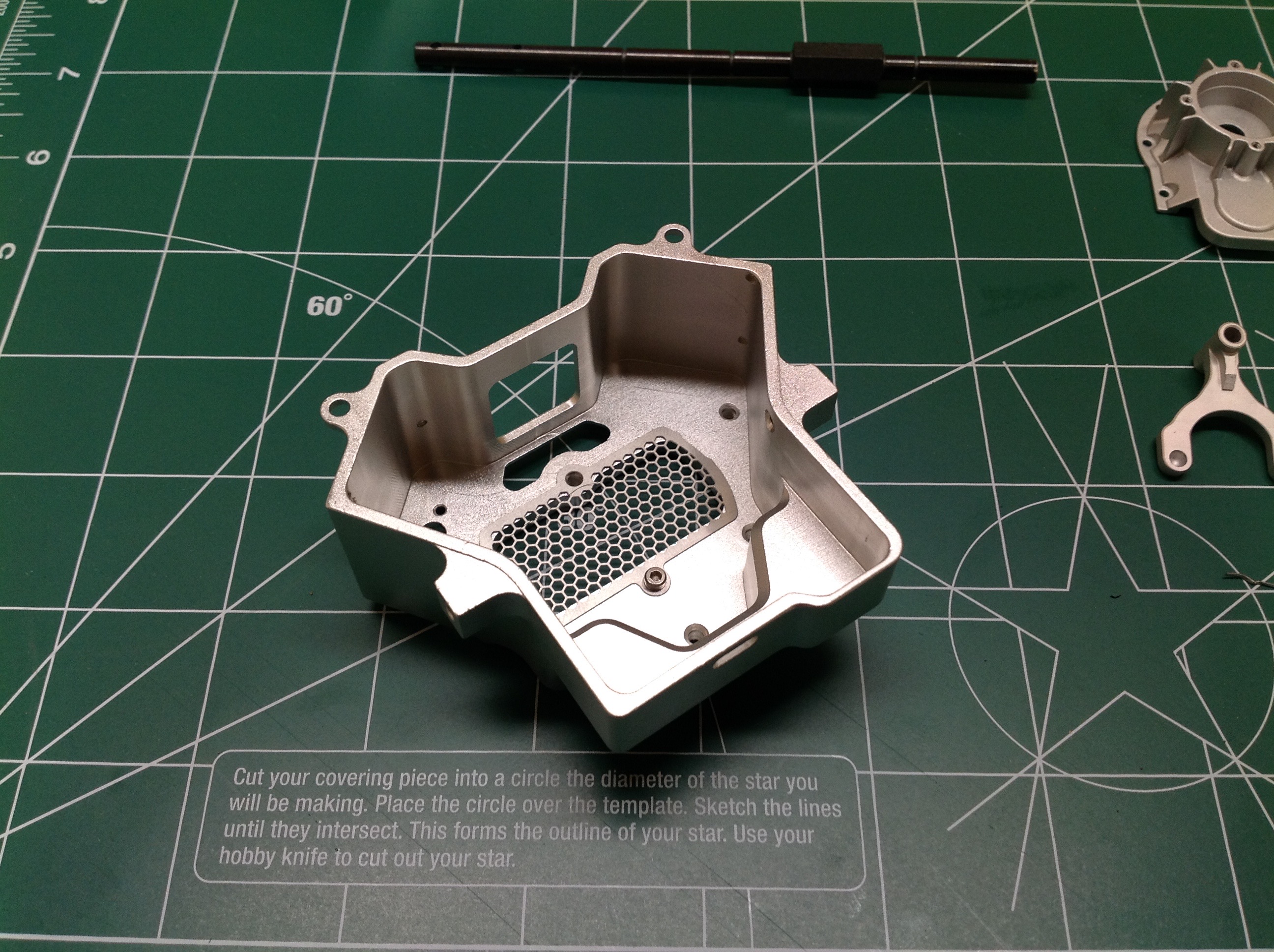
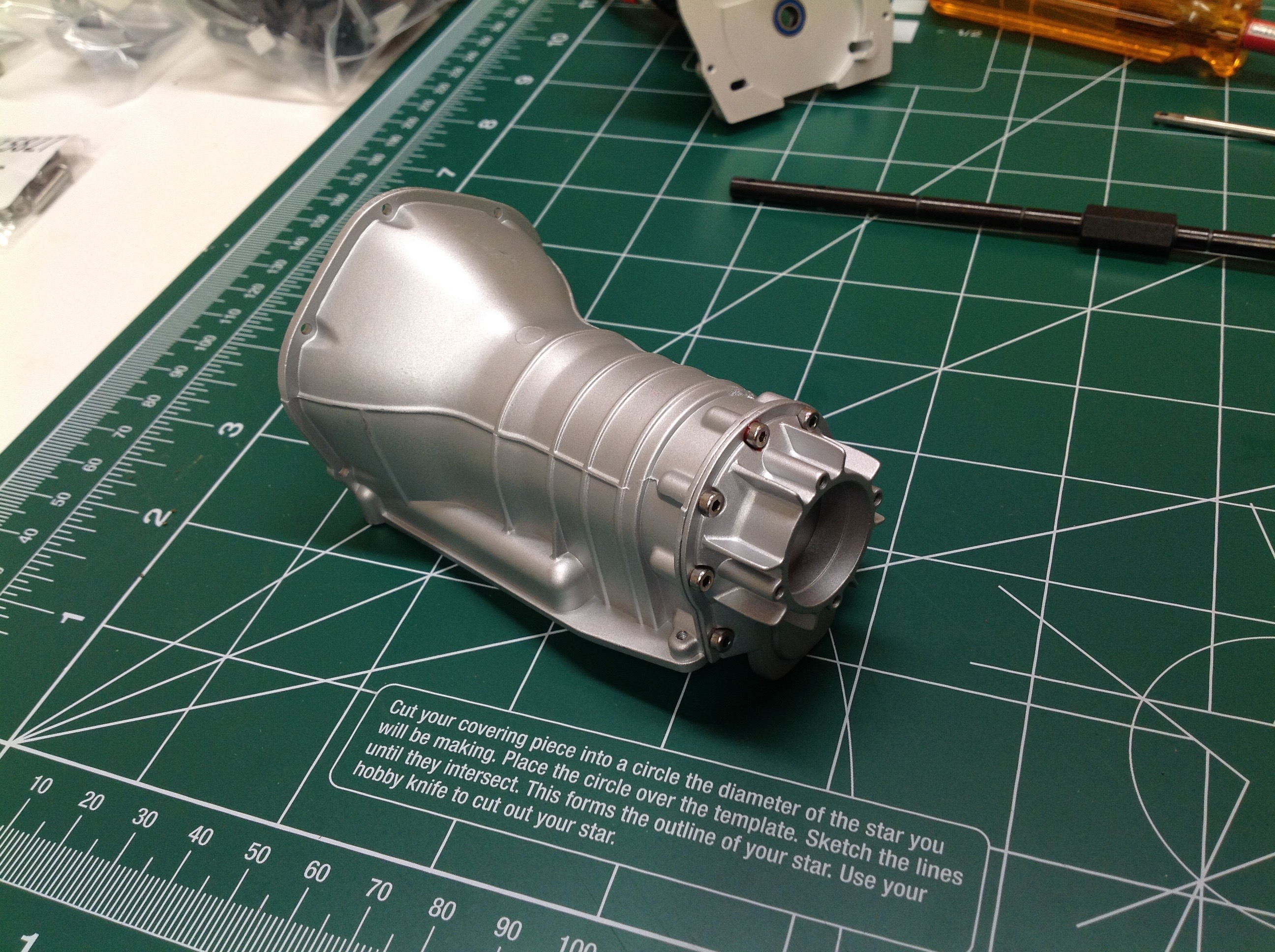
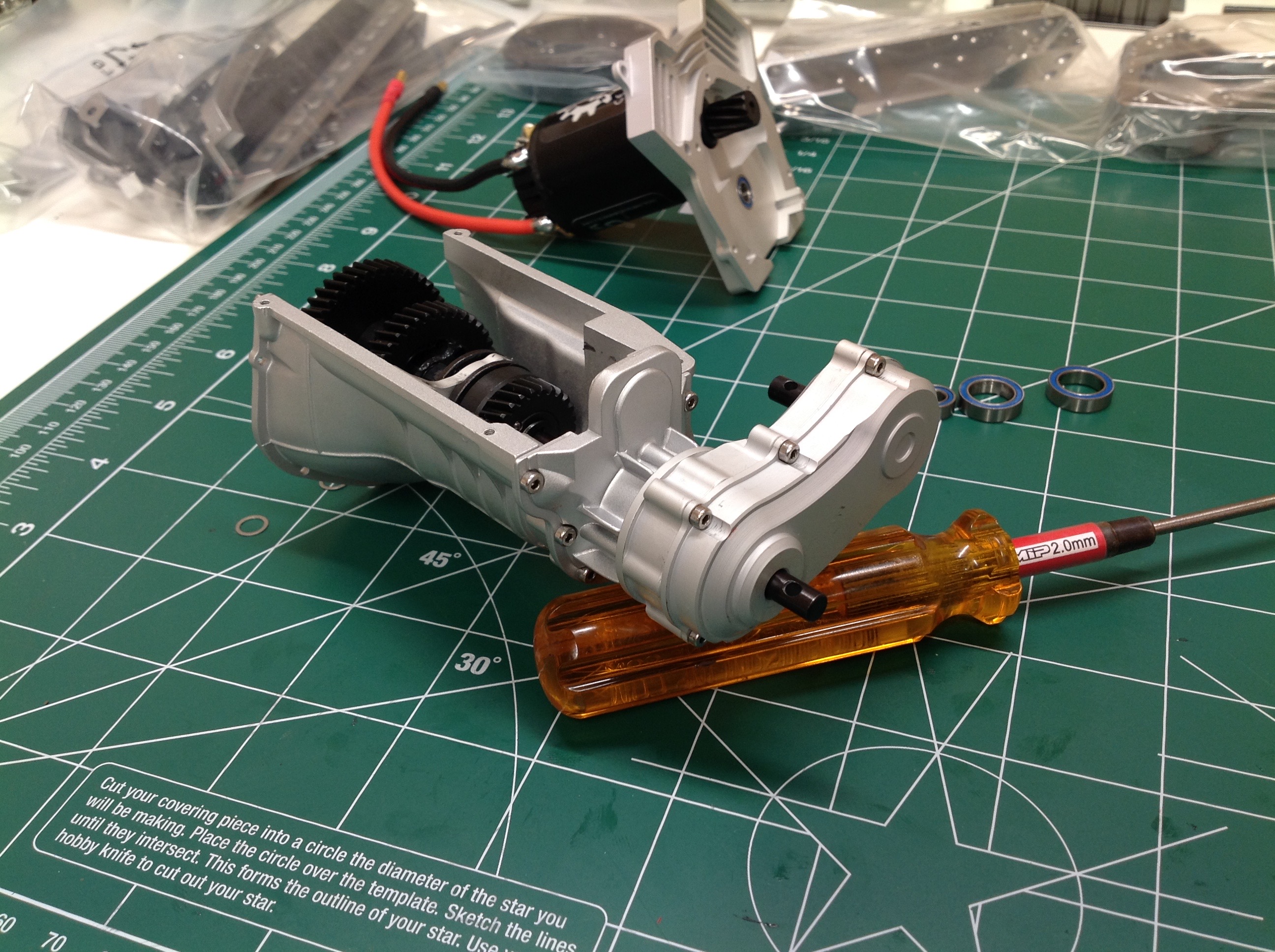
Now we build the transmission housing which is a thing of pure
beauty. It looks just like a full scale version. First you
install the rear cover to the bell housing and then the t-case front
cover is installed. In this photo I actually installed the t-case
backwards; it should be facing to the left. I didn't figure it out
until I tried to install the engine later.
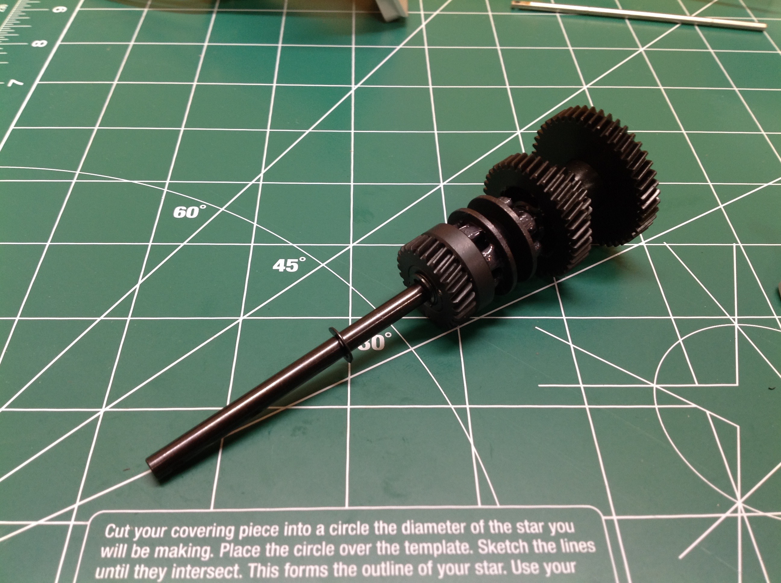
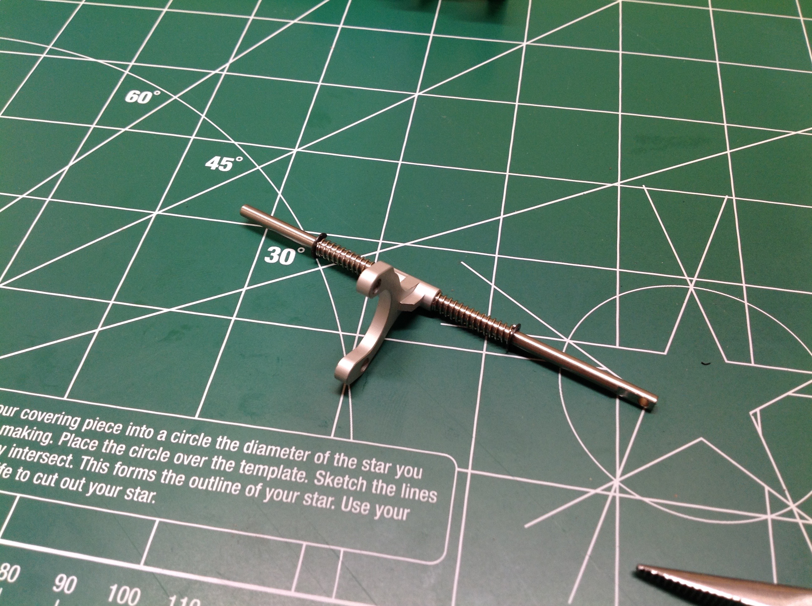
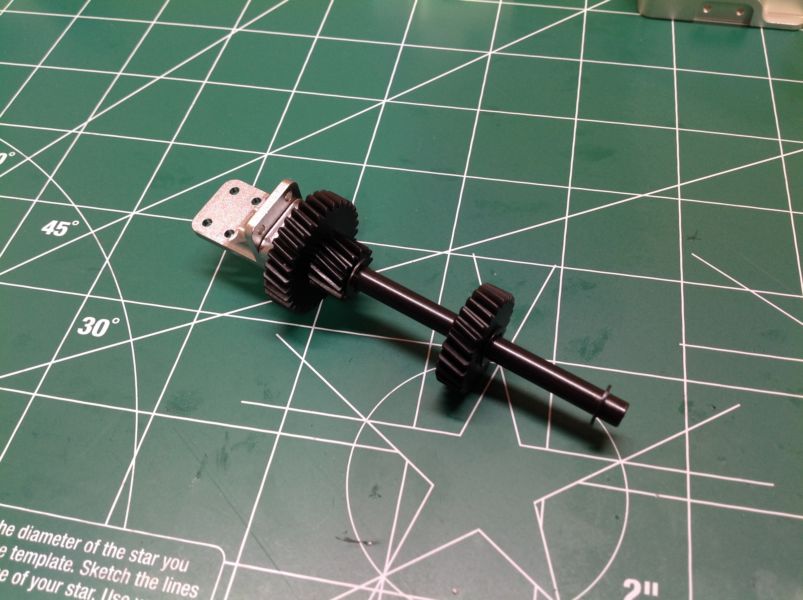
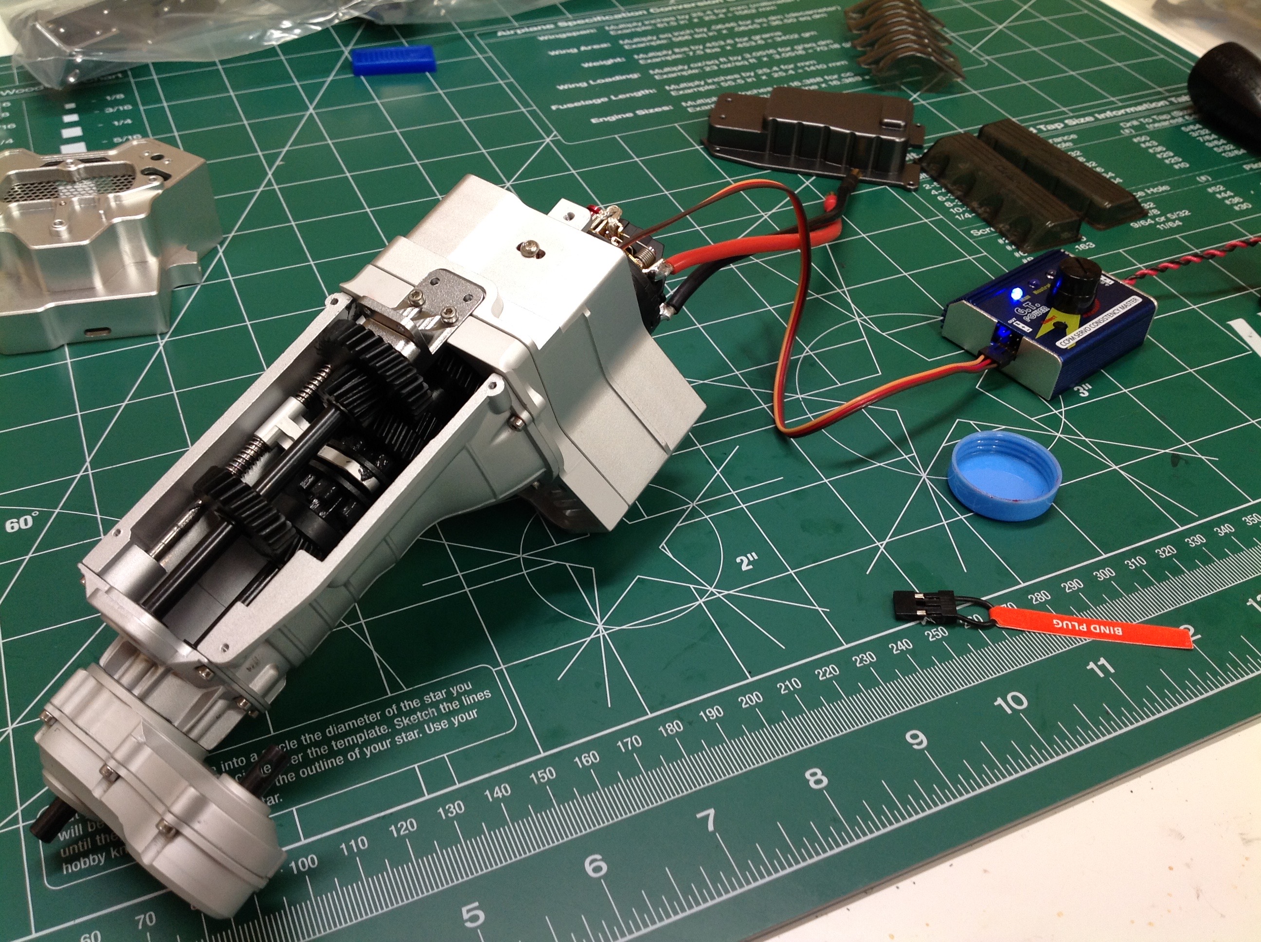
Here's the primary shaft. The driving ring is in the middle and
uses drive dogs to engage the gears on either side. You can see
the helical profile of the teeth in these images.
This is the shift fork which engages the driving ring to shift
gears. It slides back and forth using external servo input.
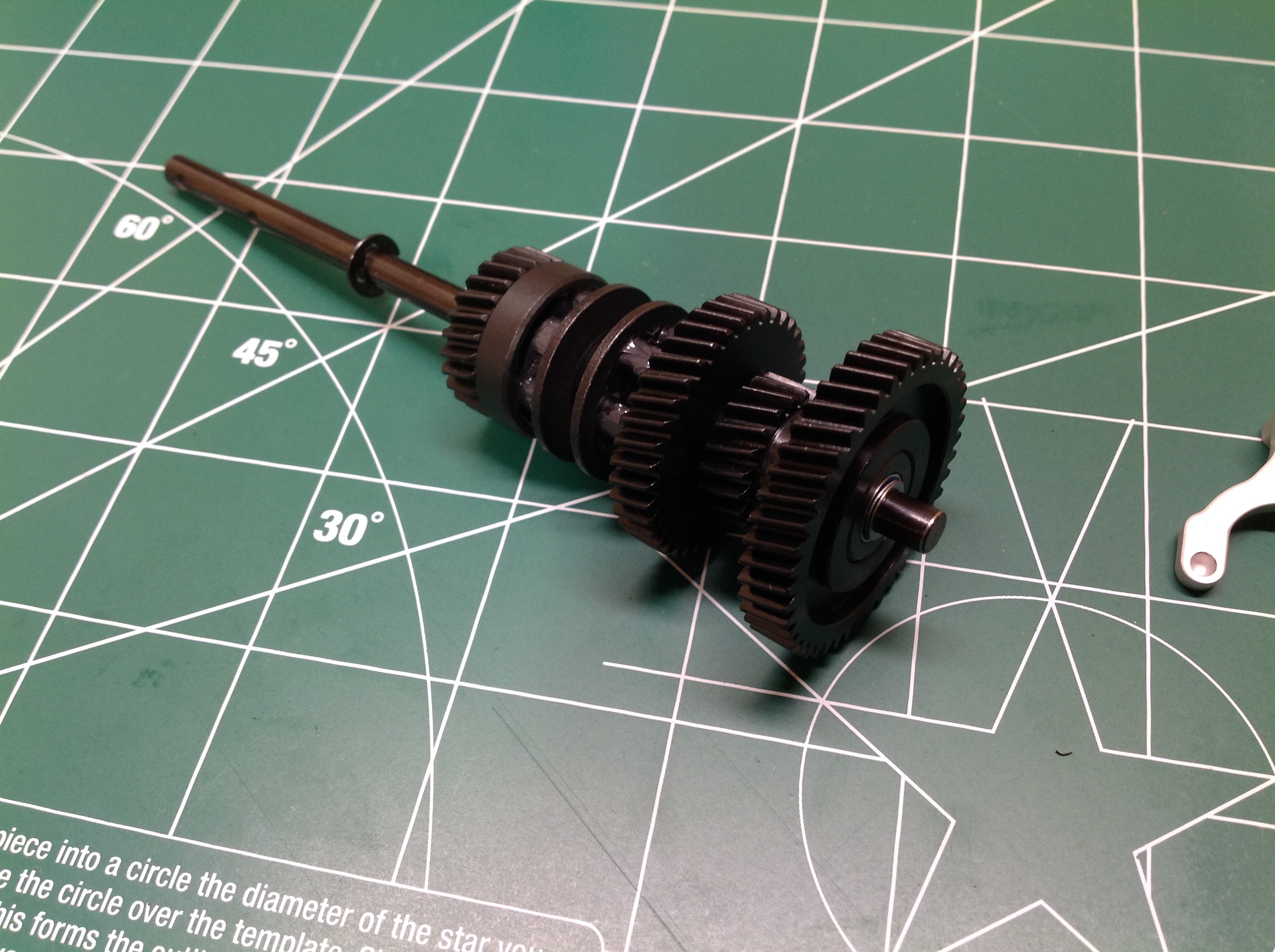
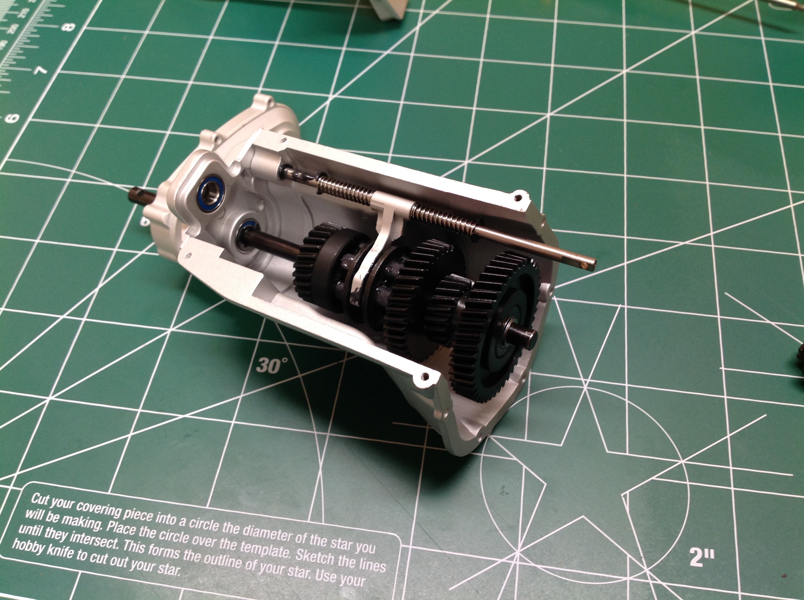
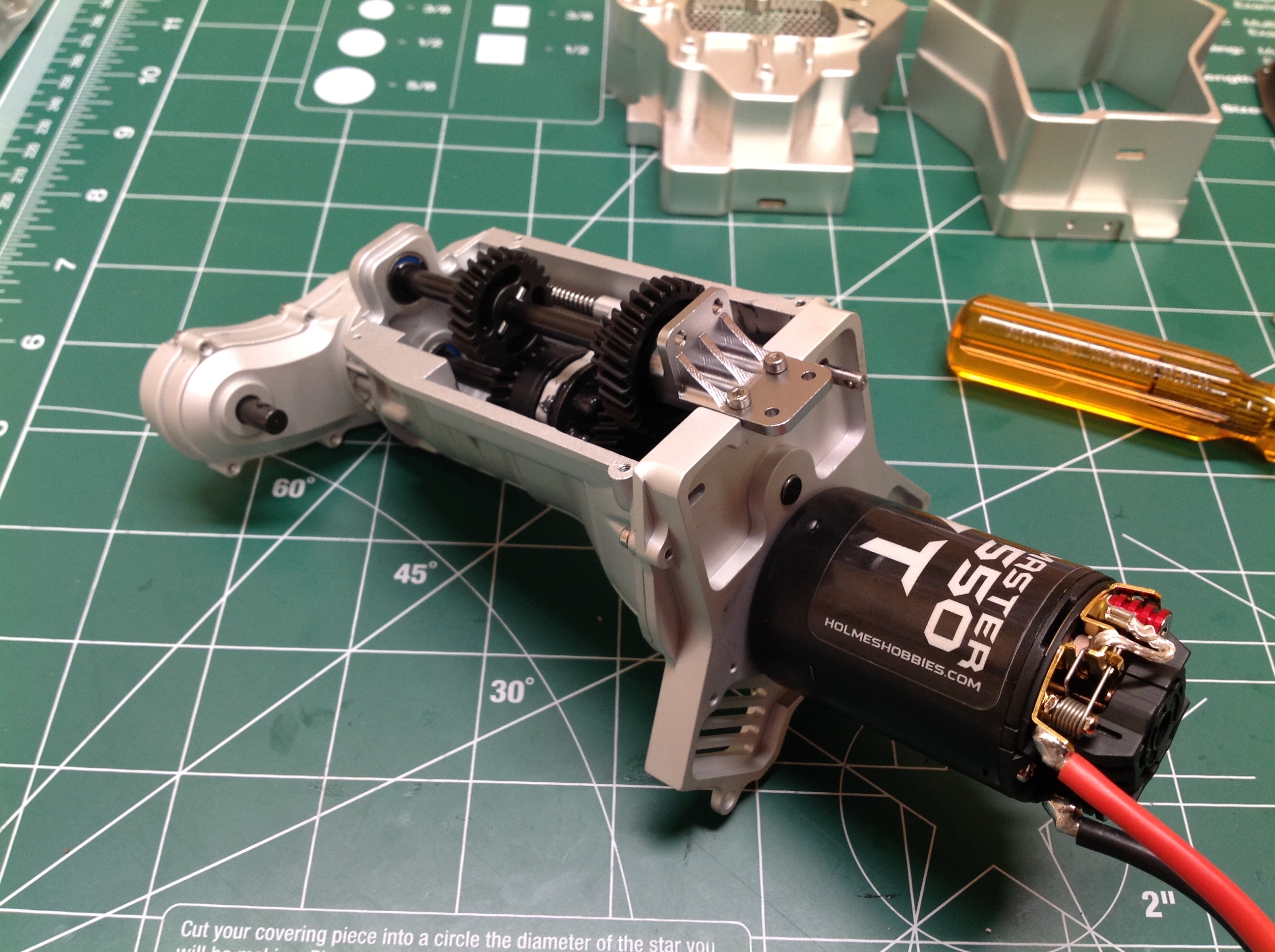
On the right the primary shaft and shift fork are installed into the
housing. I have not greased anything yet at this point. This
is an unusual gearbox design in that the primary shaft is also the
output shaft. The gear you see on the far right is the spur gear
which will mate with the motor pinion. This gear rolls freely on
the main shaft as do all the other gears. The smaller gear just to
the left of the spur is integral to it. It interfaces with the
secondary shaft which spins at a constant rate relative to the
motor. The two output gears on the secondary shaft transfer torque
back to the main shaft gears which then rotates at one of two ratios
depending on which gear is engaged. The driving ring is the only
thing locked to the main (output) shaft so that whatever it engages
drives the output. Clever!
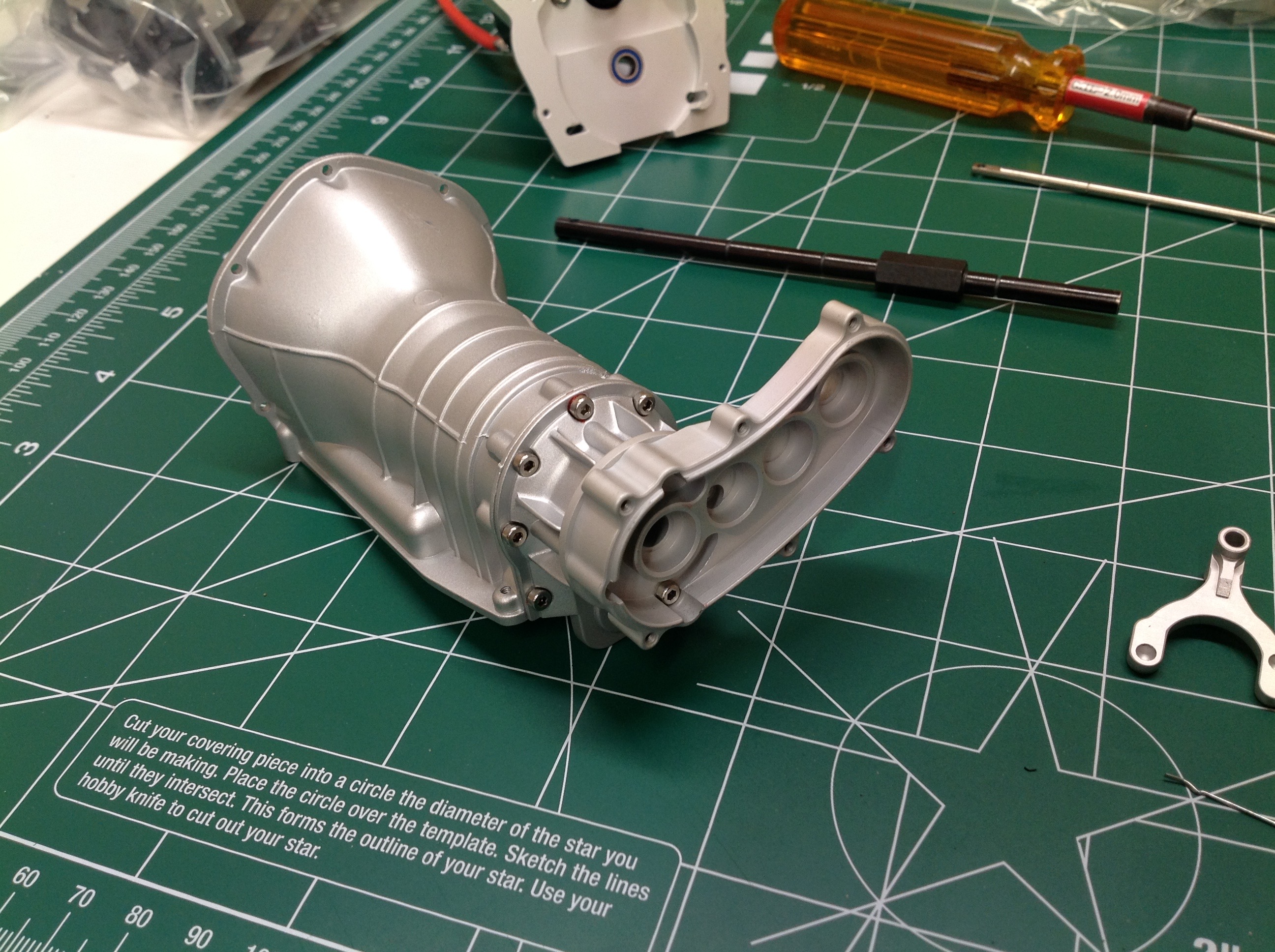
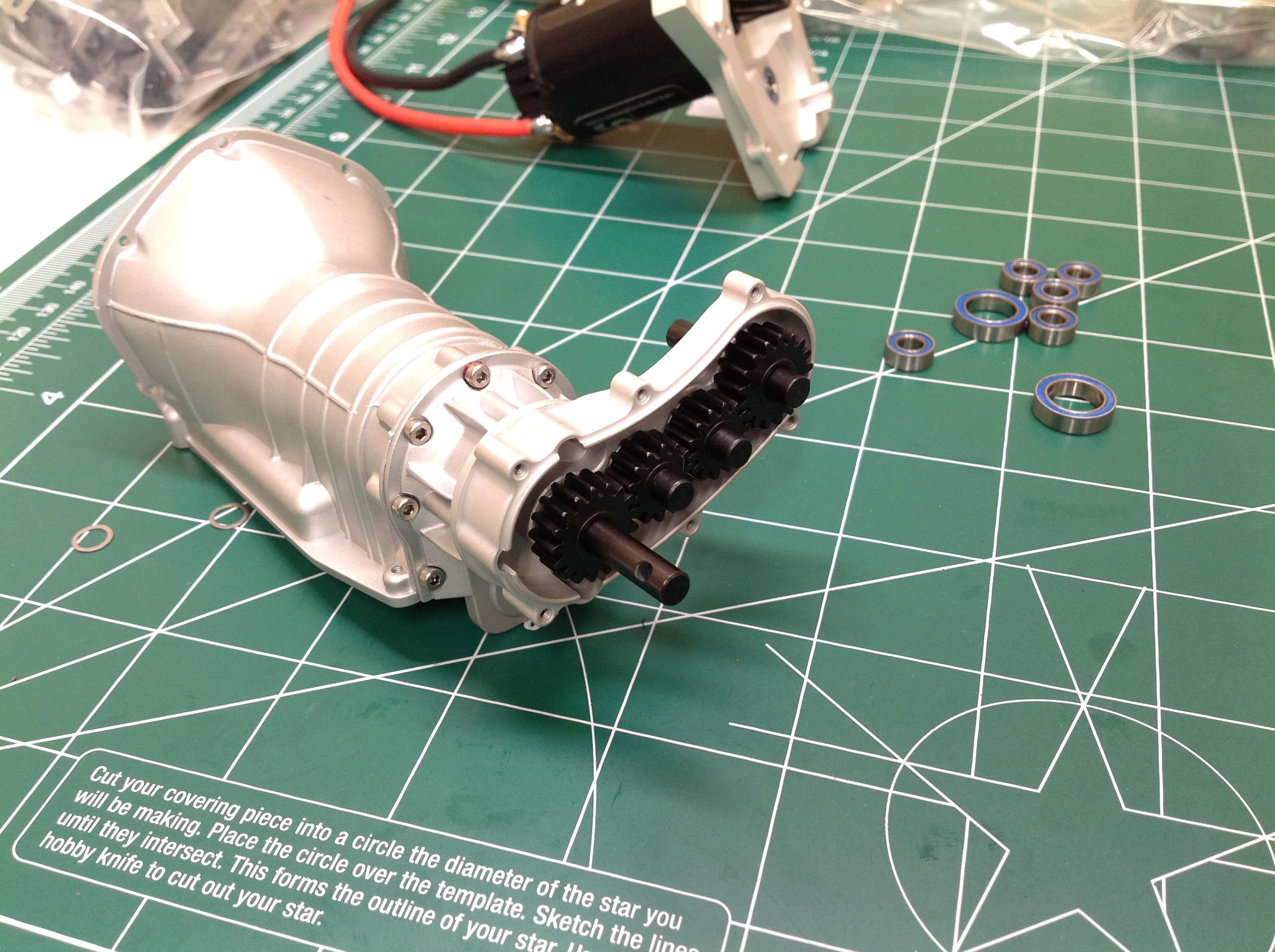
Now we install the straight cut gears in the transfer case. Since
there are an even number of gears, the forward and rear drive shafts
rotate in opposite directions which prevents torque roll. In the
right hand image I have finally noticed that I installed the t-case
backwards and have corrected it. This completes Step 1.
Step 2 adds a bunch more parts to the engine to button everything
up. In the picture on the left you can see the first plastic parts
which include the valve covers and the intake manifold. On the
right you can see the transmission secondary shaft.
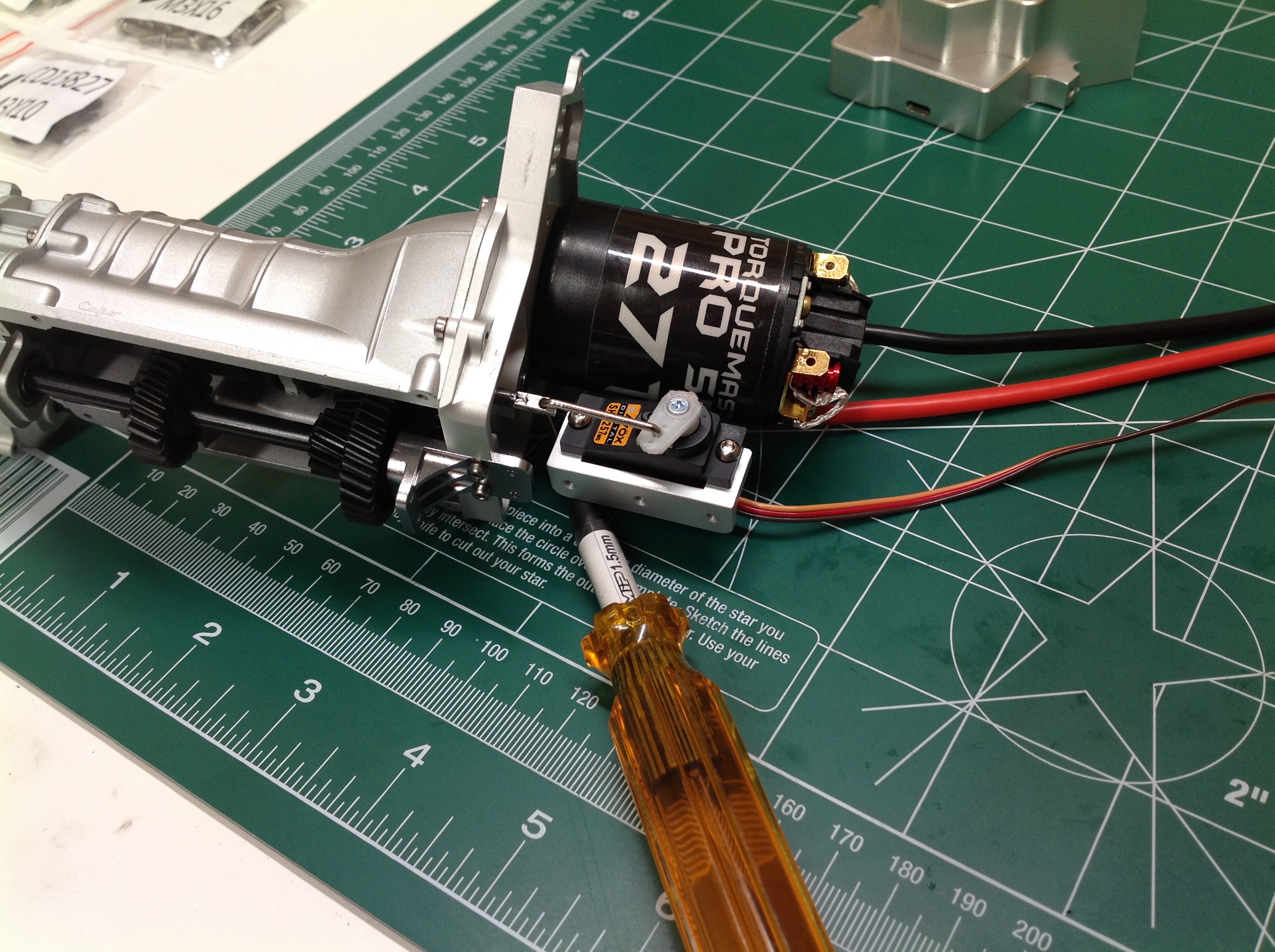
The secondary shaft inserts into a bearing on the far end and is
supported by a bracket housing another bearing on the other. The
next thing to do is install the shift servo. The shifting system
uses a micro servo which is housed inside the engine case so it won't be
seen. It takes a little fiddling to get it adjusted. You
want to get it right now because it will be very difficult to access
later.
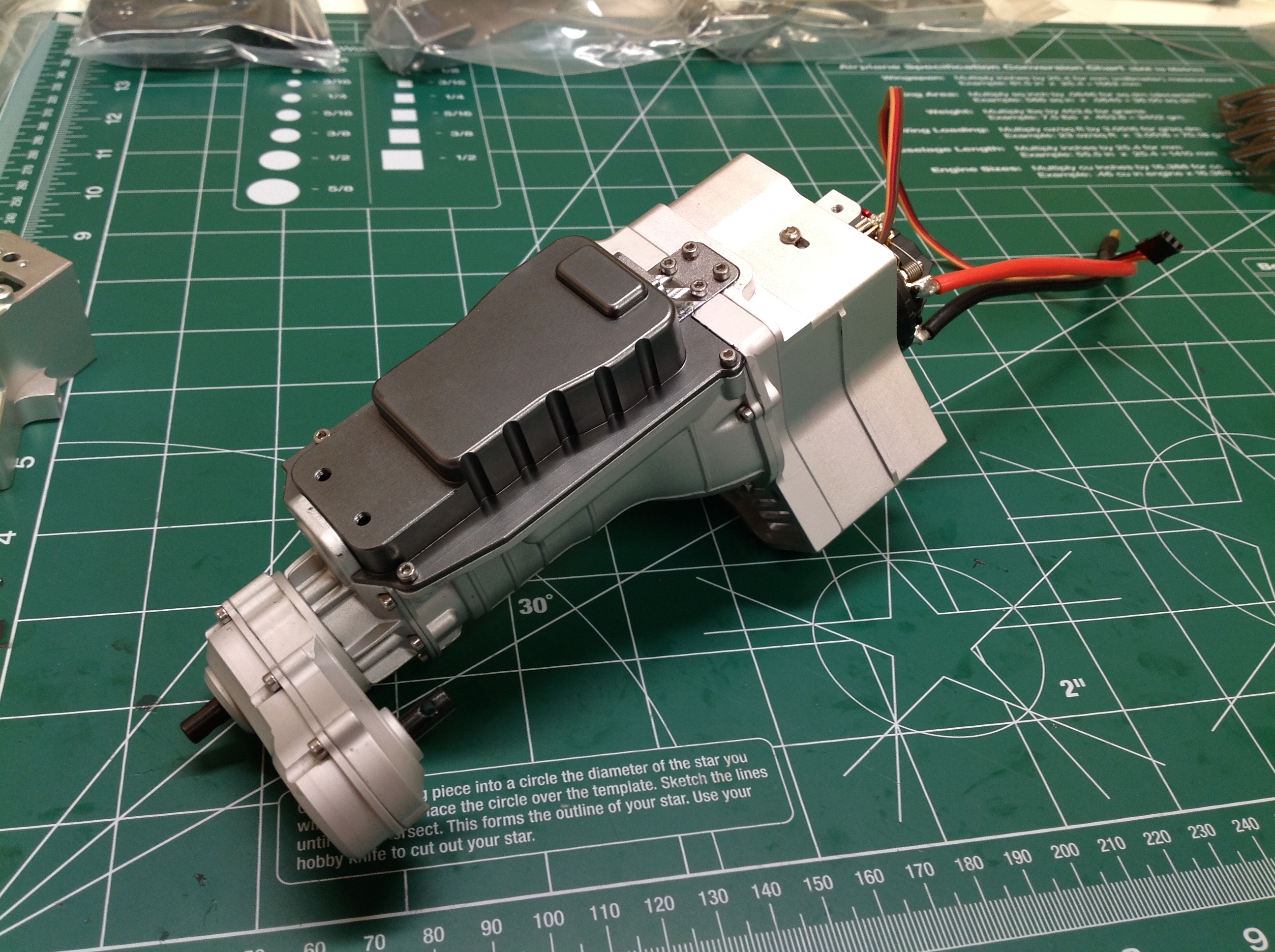
From the bottom you can see both transmission shafts and the shift fork
mechanism. I've also added the first engine block section which
covers most of the motor and shift servo. From the bottom I then
install the oil pan which is also metal.
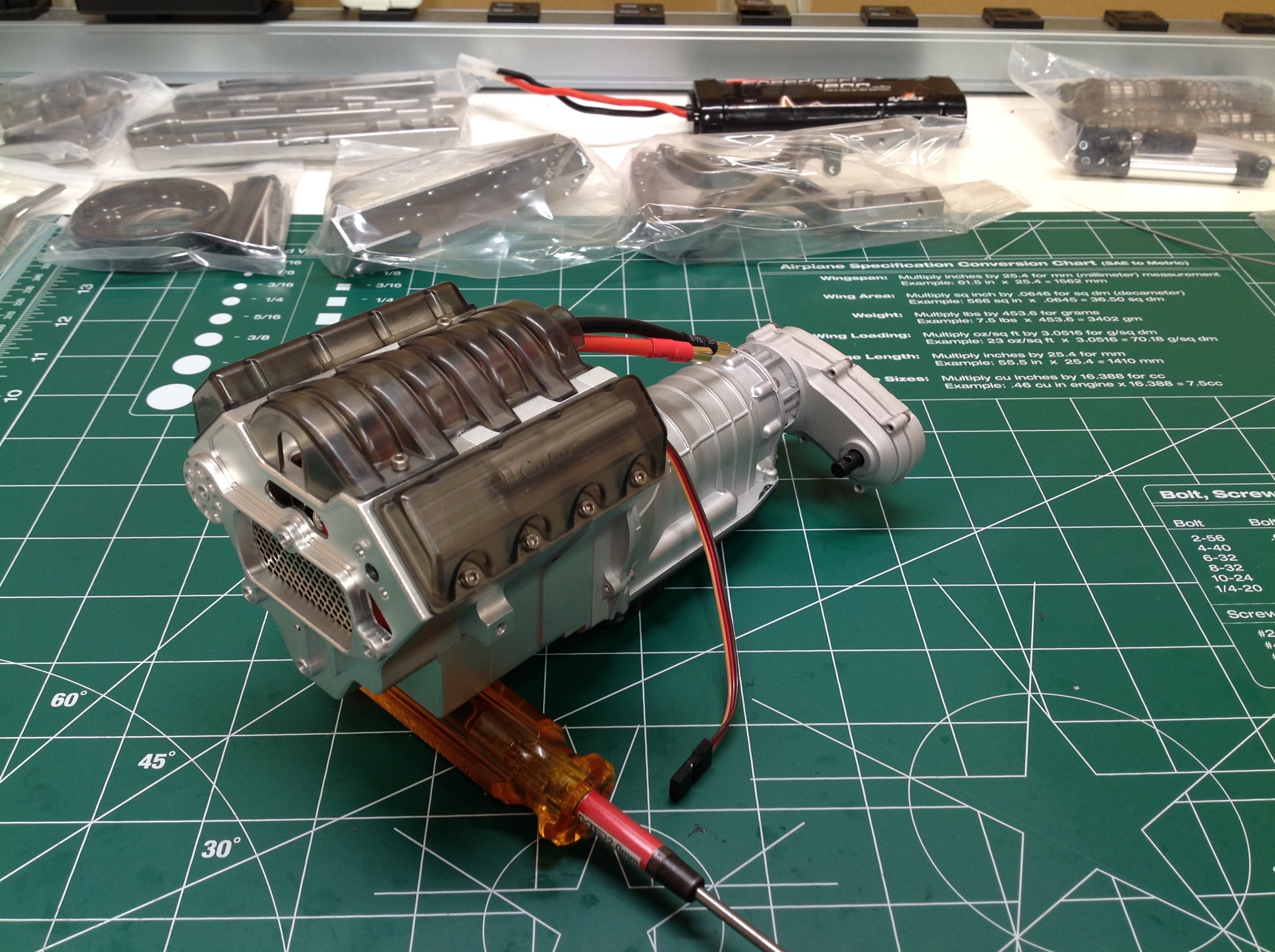
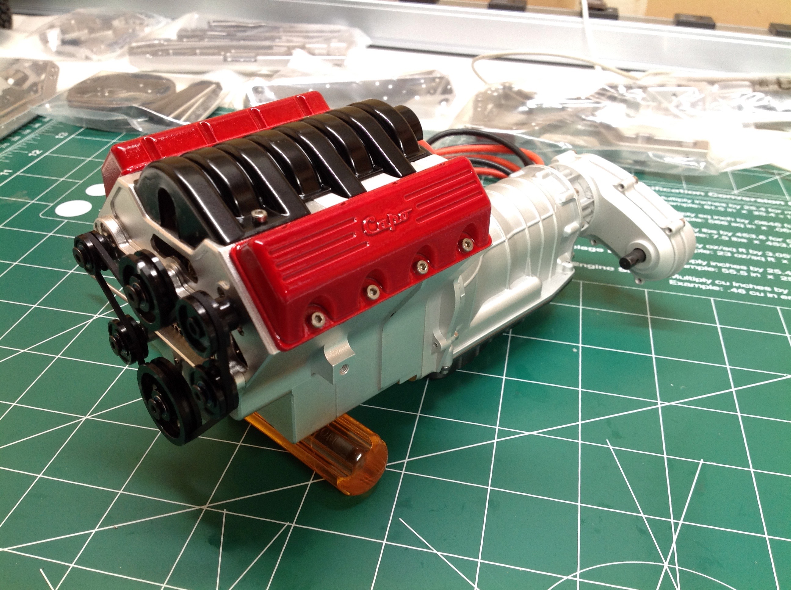
To finish up the engine I need to add the front block section and then
the plastic top bits. I painted the valve covers in the same color
as I'll later paint the body, and the intake manifold is flat
black. The last picture also shows the optional pulley system
which I'll talk about later in the upgrade section. I wanted to
add it now because it is much easier to install when the engine is apart
anyway. The final completed engine has quite a few wires sticking
out the back including those for the motor, the shift servo, and the
pulley motor.
©2018 Eric Albrecht