Capo JK Max Project
Page 2: Building the Chassis
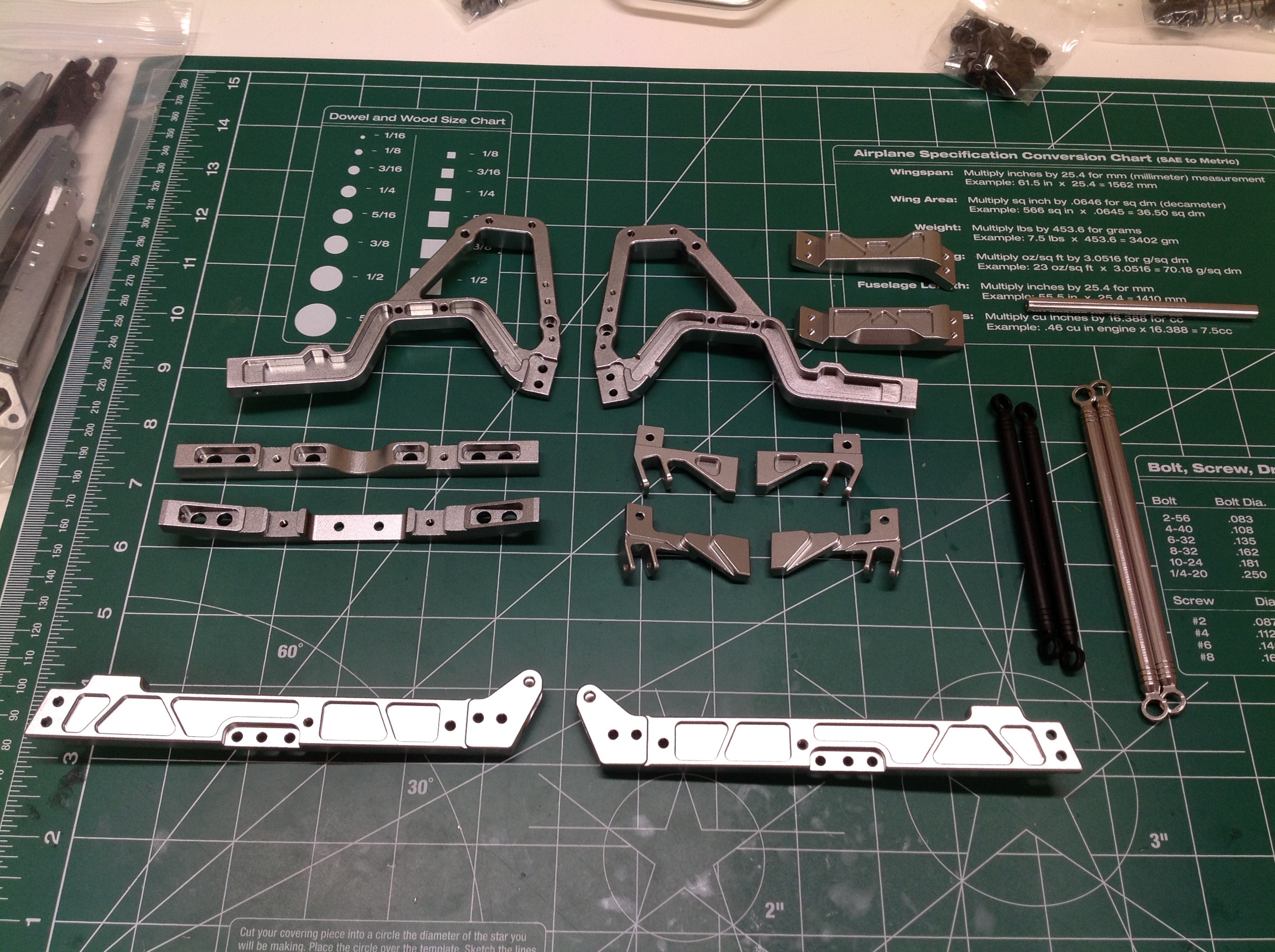
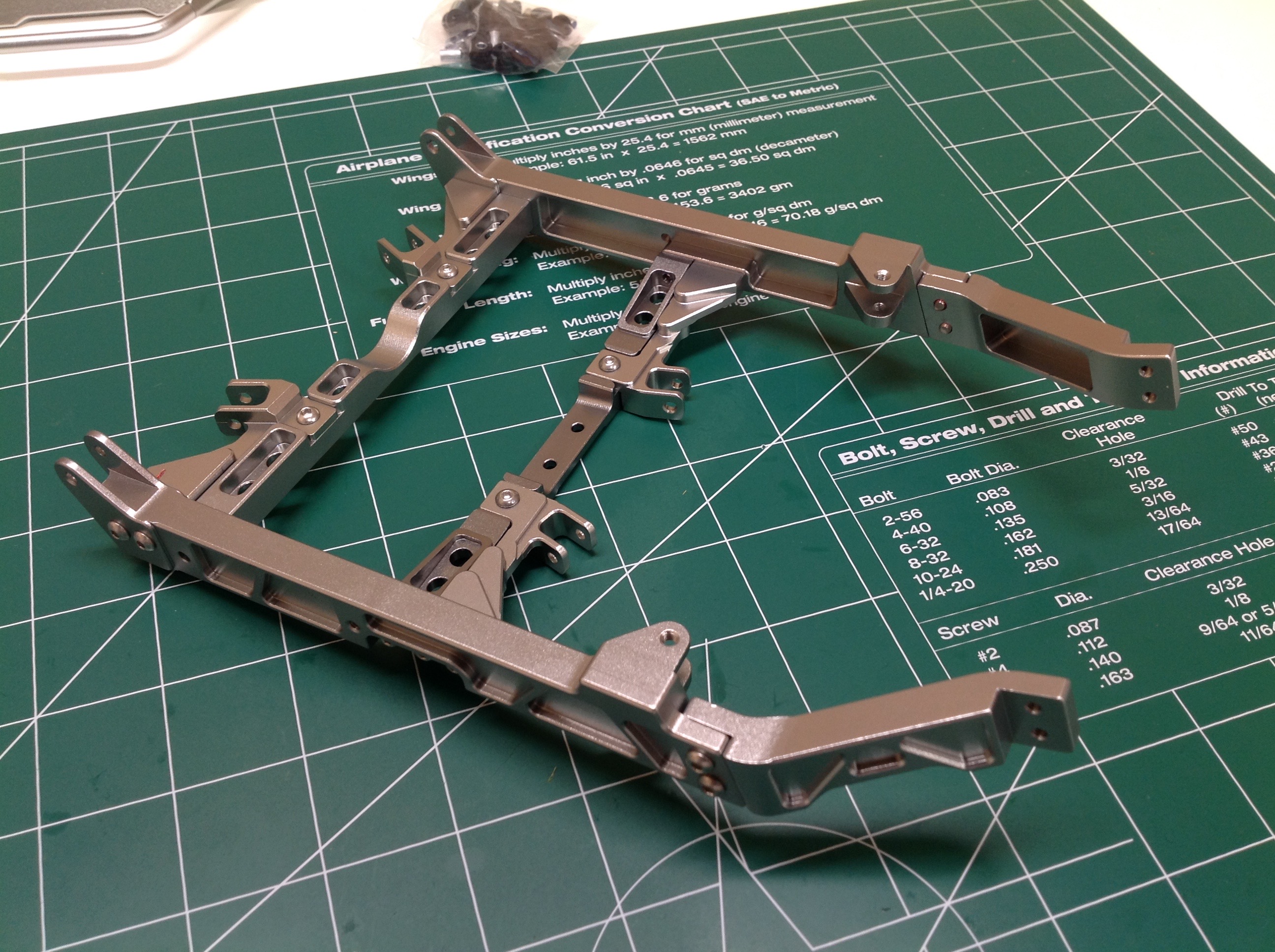
With the engine done we can get started on the frame. The pile of
milled aluminum above may not look like traditional frame parts because
the rails are not the length of the chassis. We'll see why as the
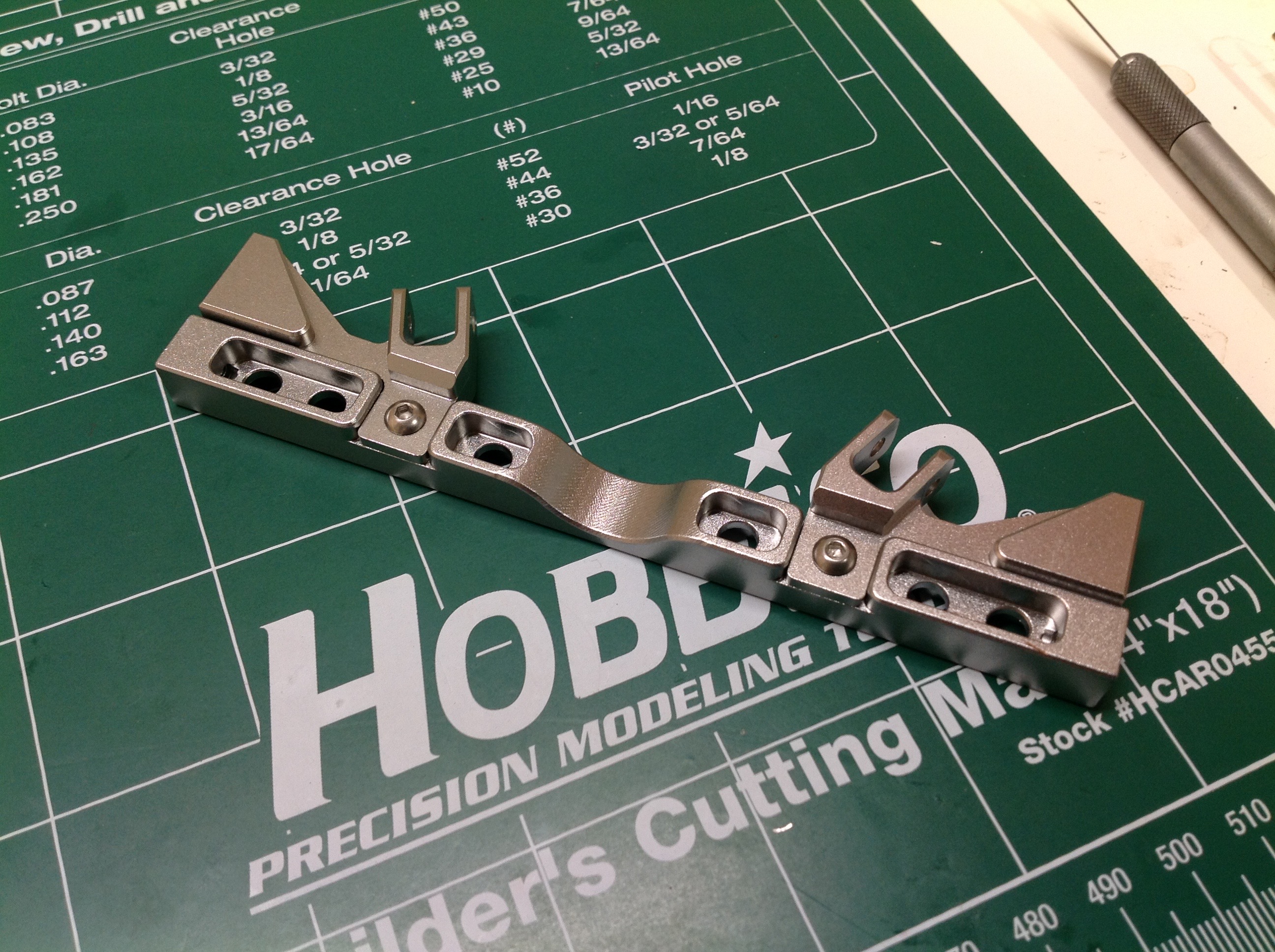
build progresses. I'll start by attaching the link supports to the
first cross member. Note that they are made with a built in angle
to point the links in the right direction without requiring a big
rotation on the ball end.
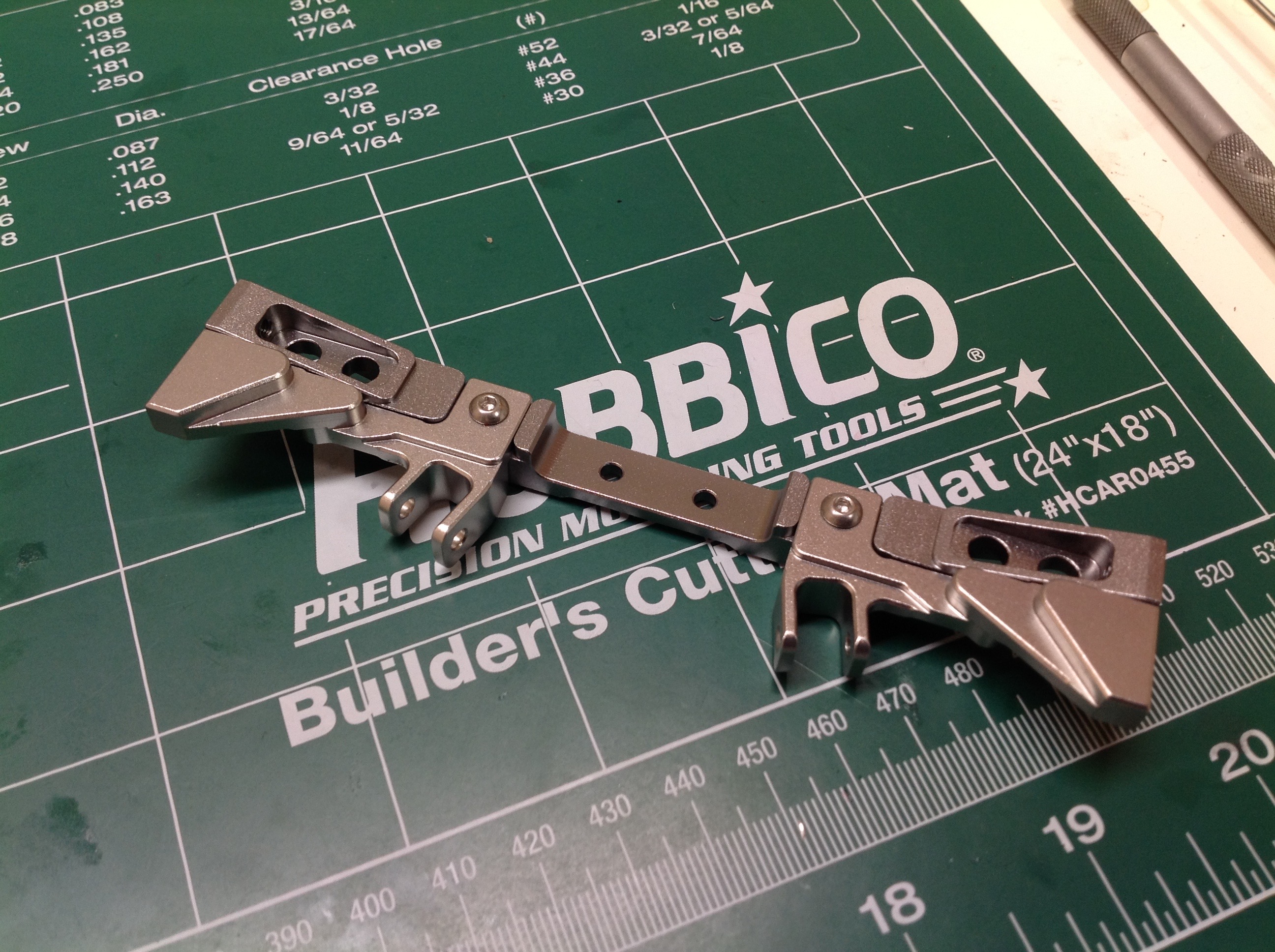
The second cross member looks much the same but isn't which means you
need to be careful to use the right parts and not confuse them.
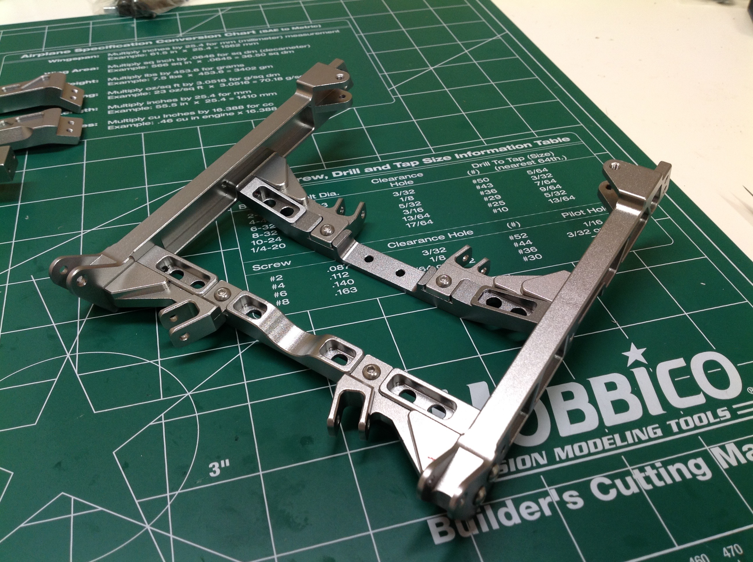
The right hand image shows both cross members attached to the frame
rails. This is a glorious chassis taking shape.
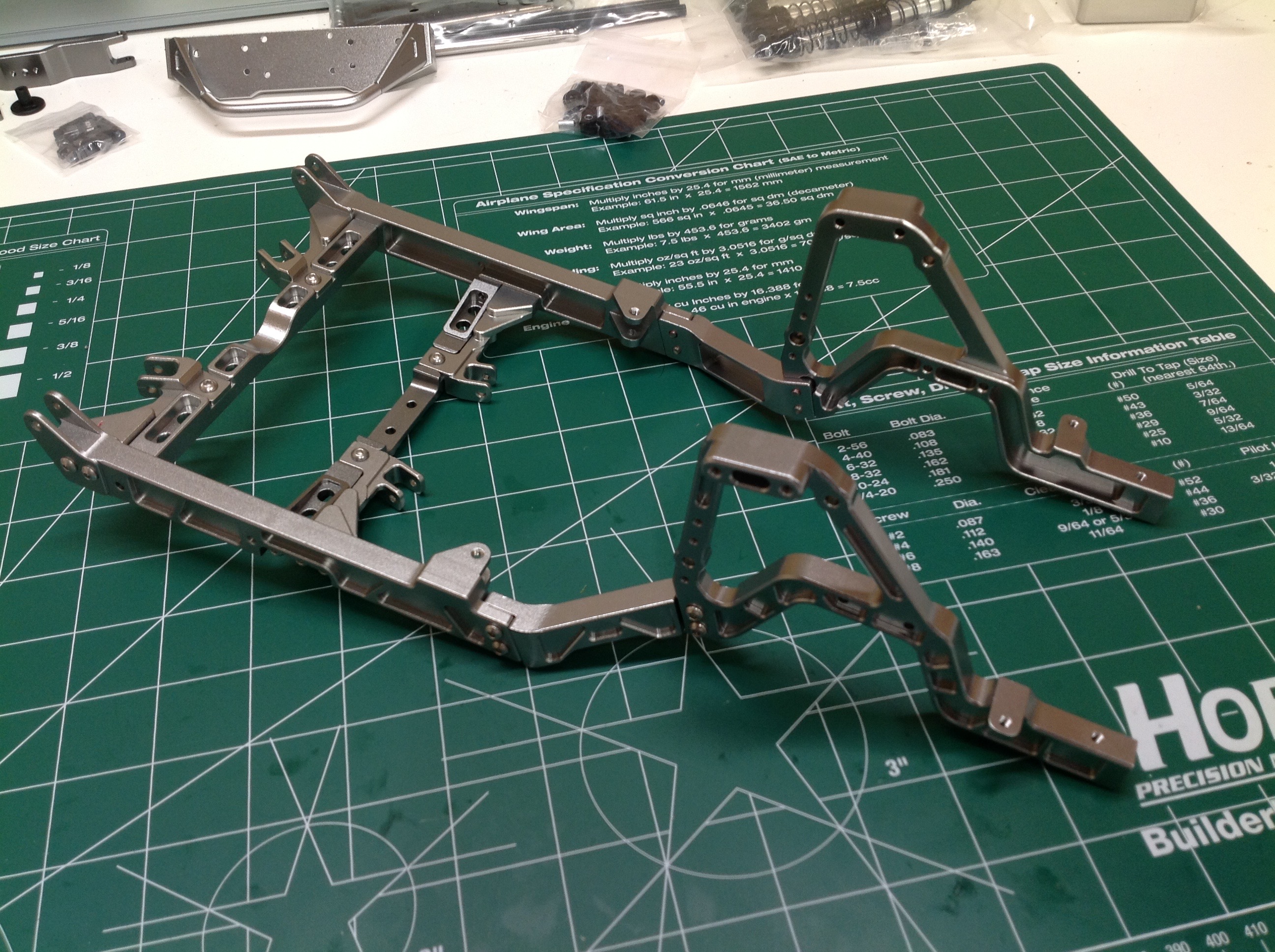
Now we'll start attaching the rail extensions for the wheel arches
followed by the huge shock hoops. The shock hoops both support the
shocks and also enclose the engine bay. Everything you see here
is milled aluminum.
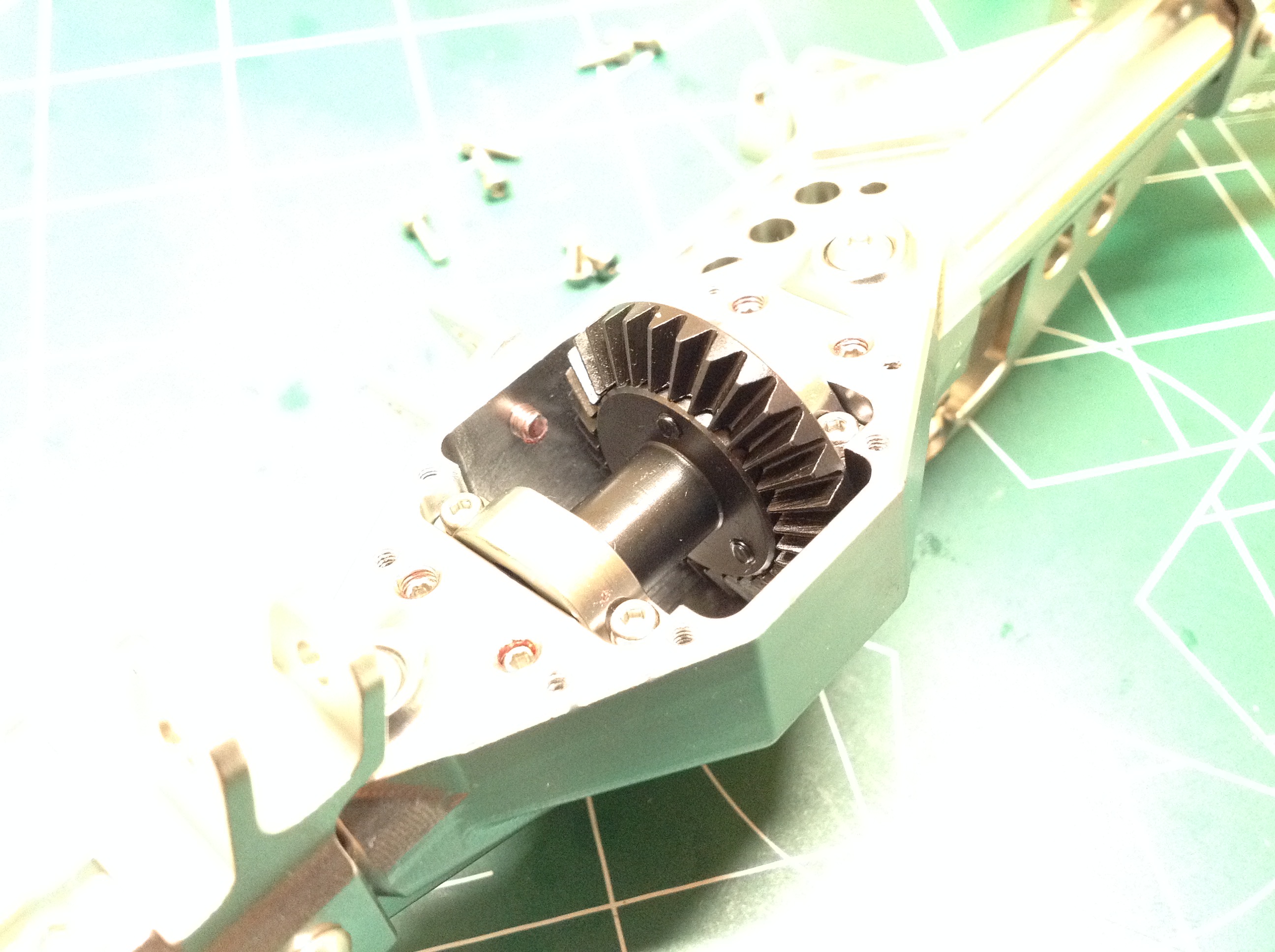
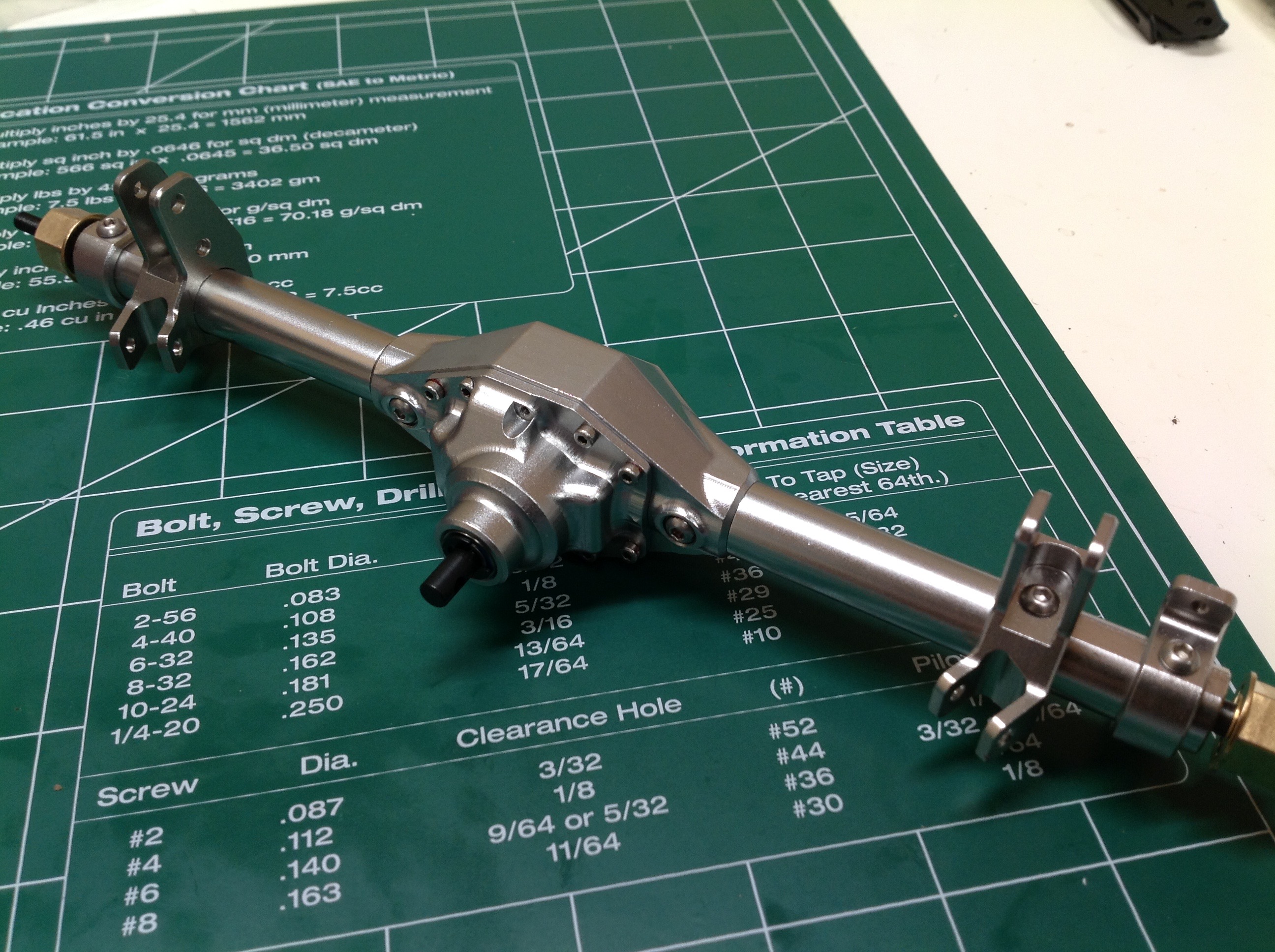
The axles come pre-assembled, but you really need to tear them down to
grease the gears and add thread lock to all the screws. There are
an amazingly large number of screws for an axle assembly. This is
the front axle. Both front and rear have a locked spool with
straight cut gears for strength. You can see the pillow blocks on
either side of the differential for bearing support. The steel
axles have CVD ends.
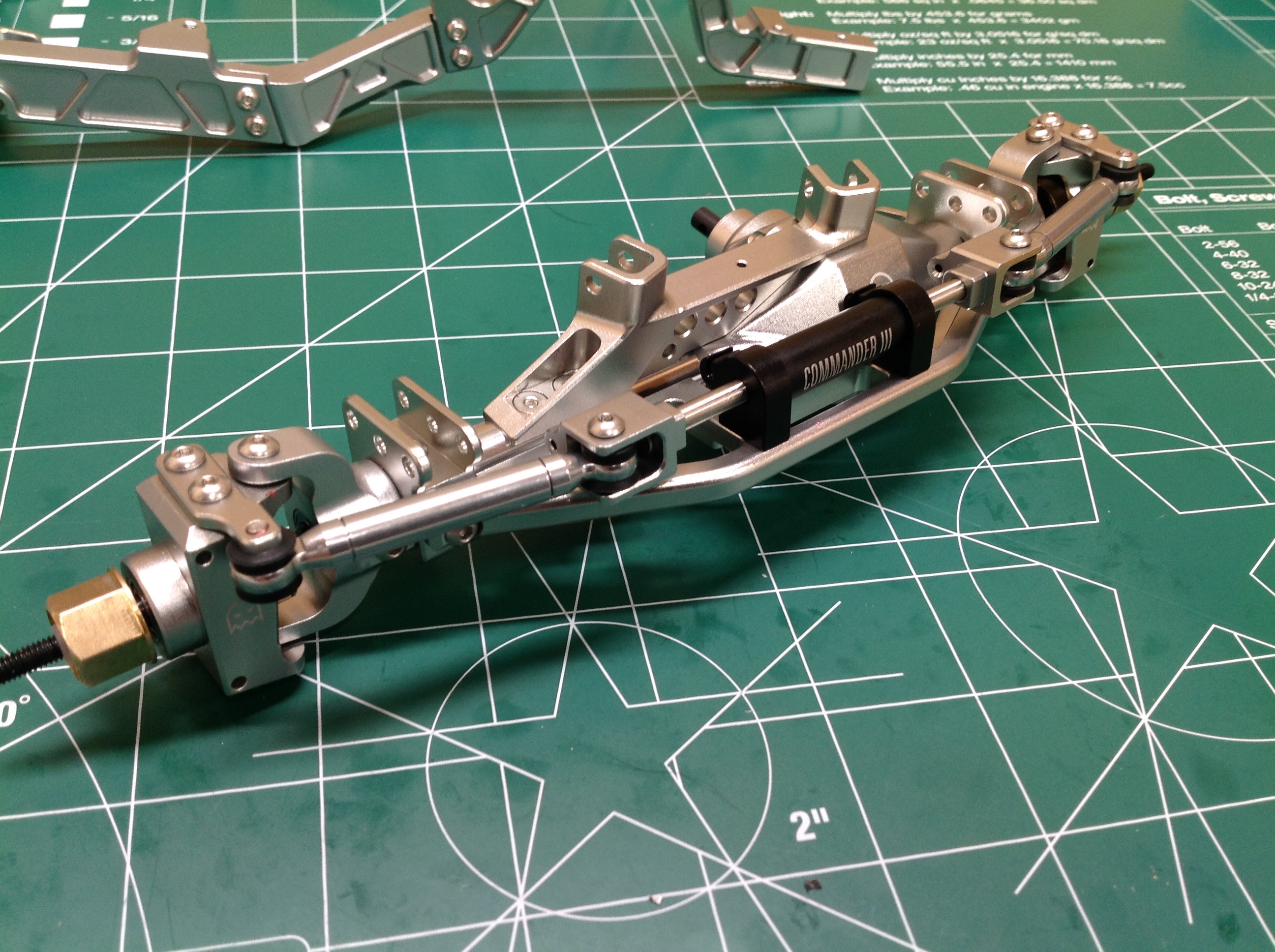
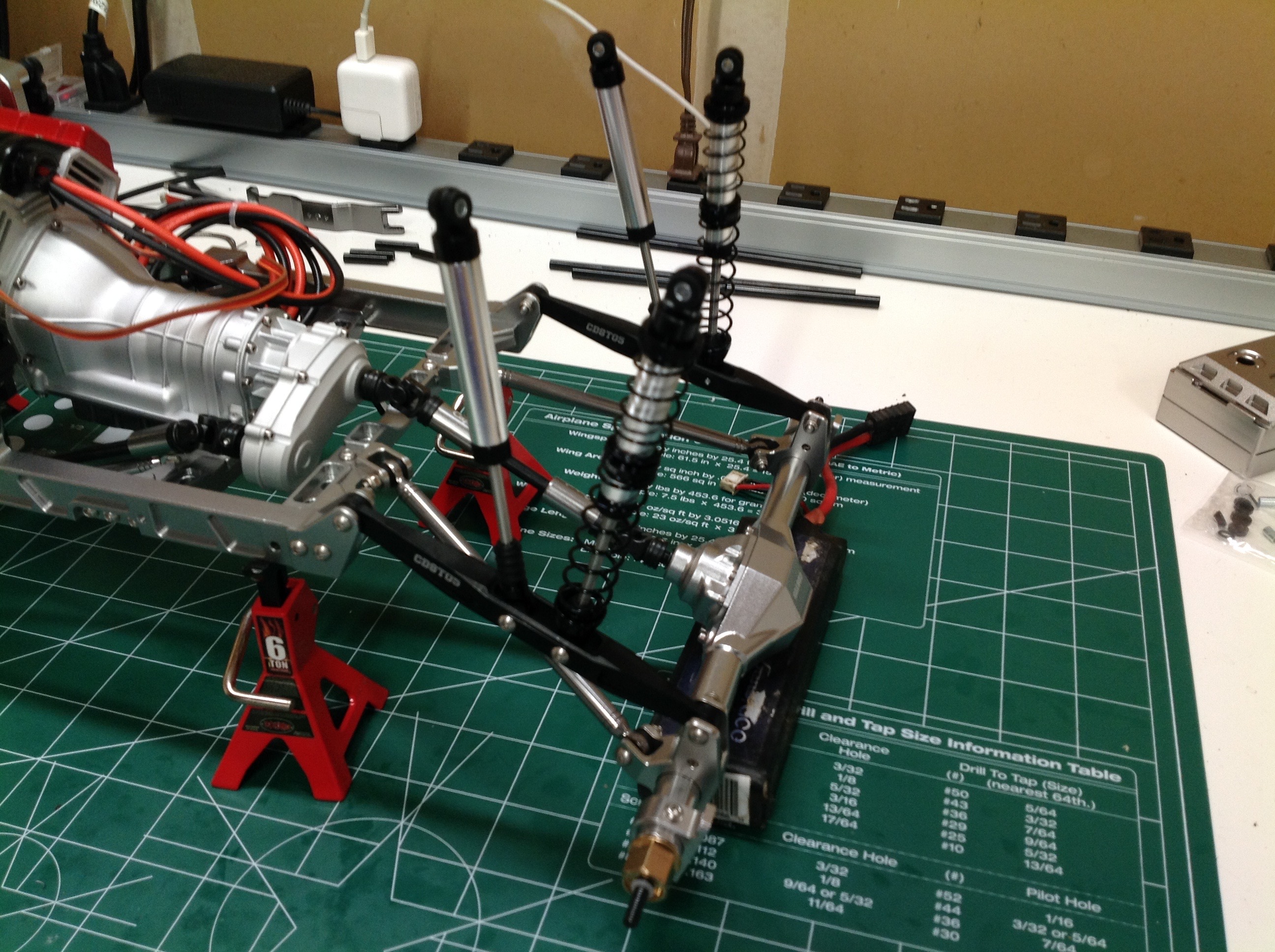
That's got to be the most beautiful front axle I've ever seen. The
steering tie rod is not just a straight link. Instead it passes
through the "Commander" steering stabilizer unit in the center.
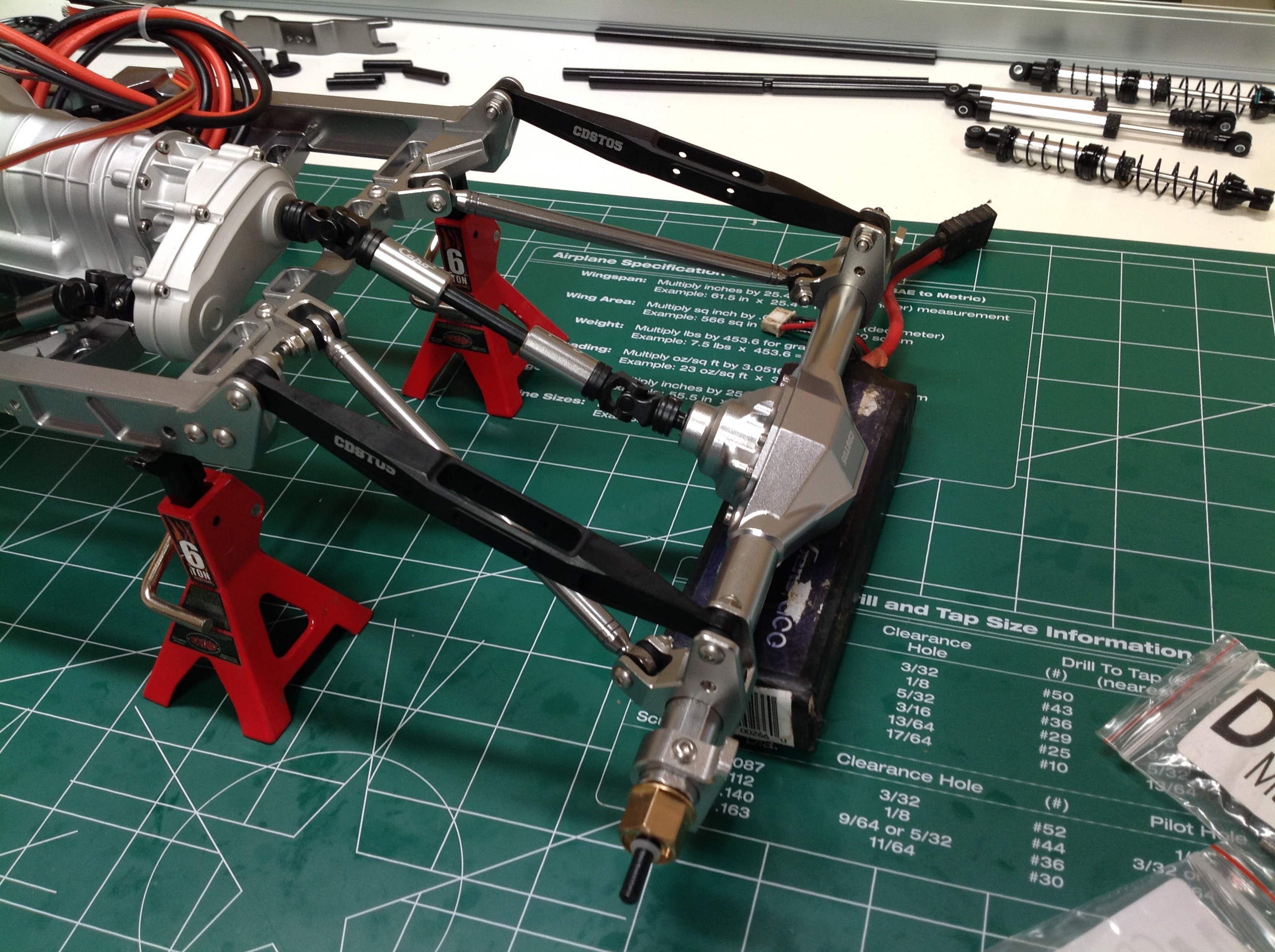
The hubs have geometry for Ackerman correction. The right hand
image shows the front axle installed on the frame. The longer
lower links are silver and the upper links are black. All the
links are milled one-piece units and therefore the rod ends can never
back out. There are rubber bushings on all the ball joints,
including the steering.
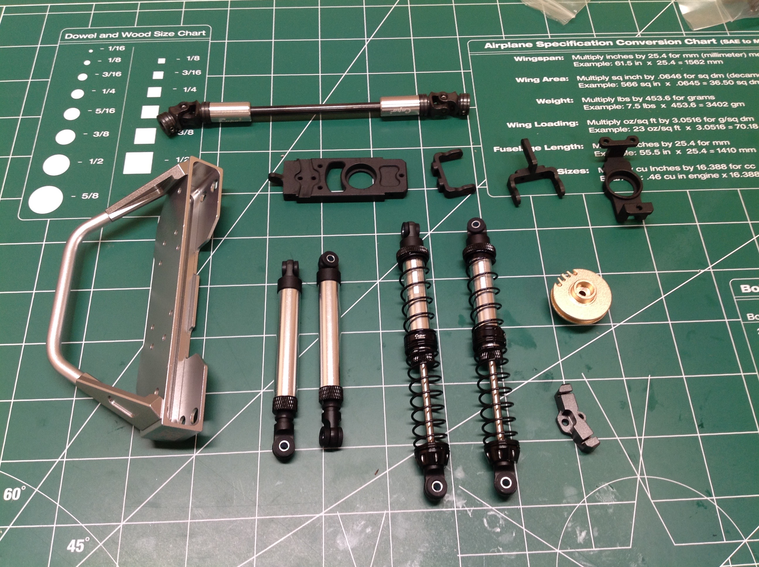
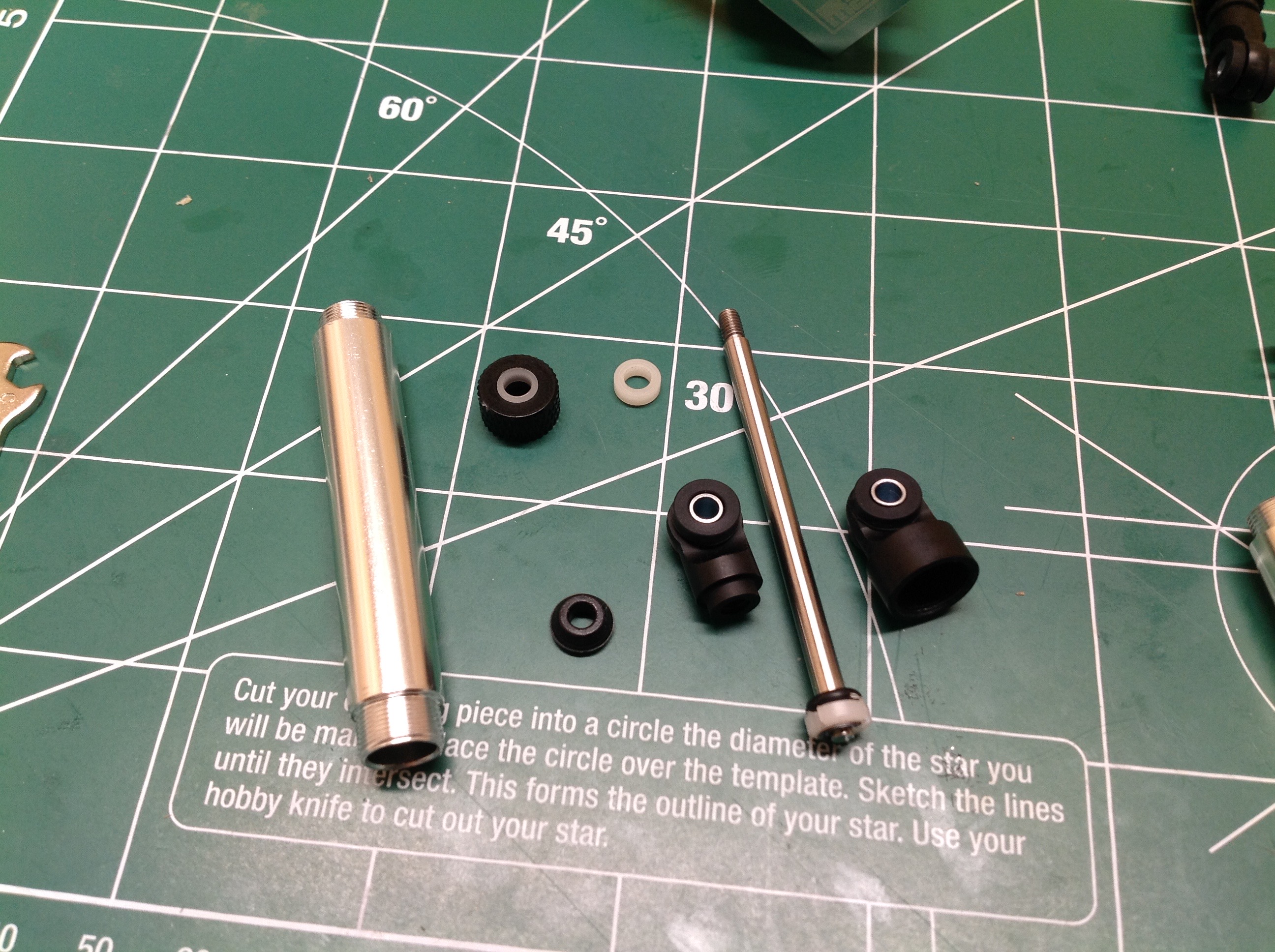
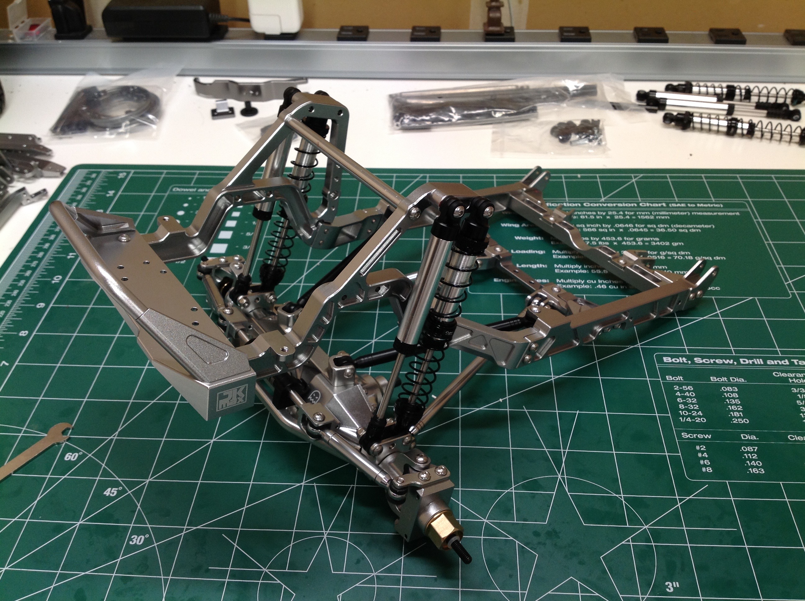
Here are the parts for Step 4 which includes the shocks, the front drive
shaft, the steering, and the front bumper. The shocks appear to
be pre-assembled, but you actually have to tear them down before using
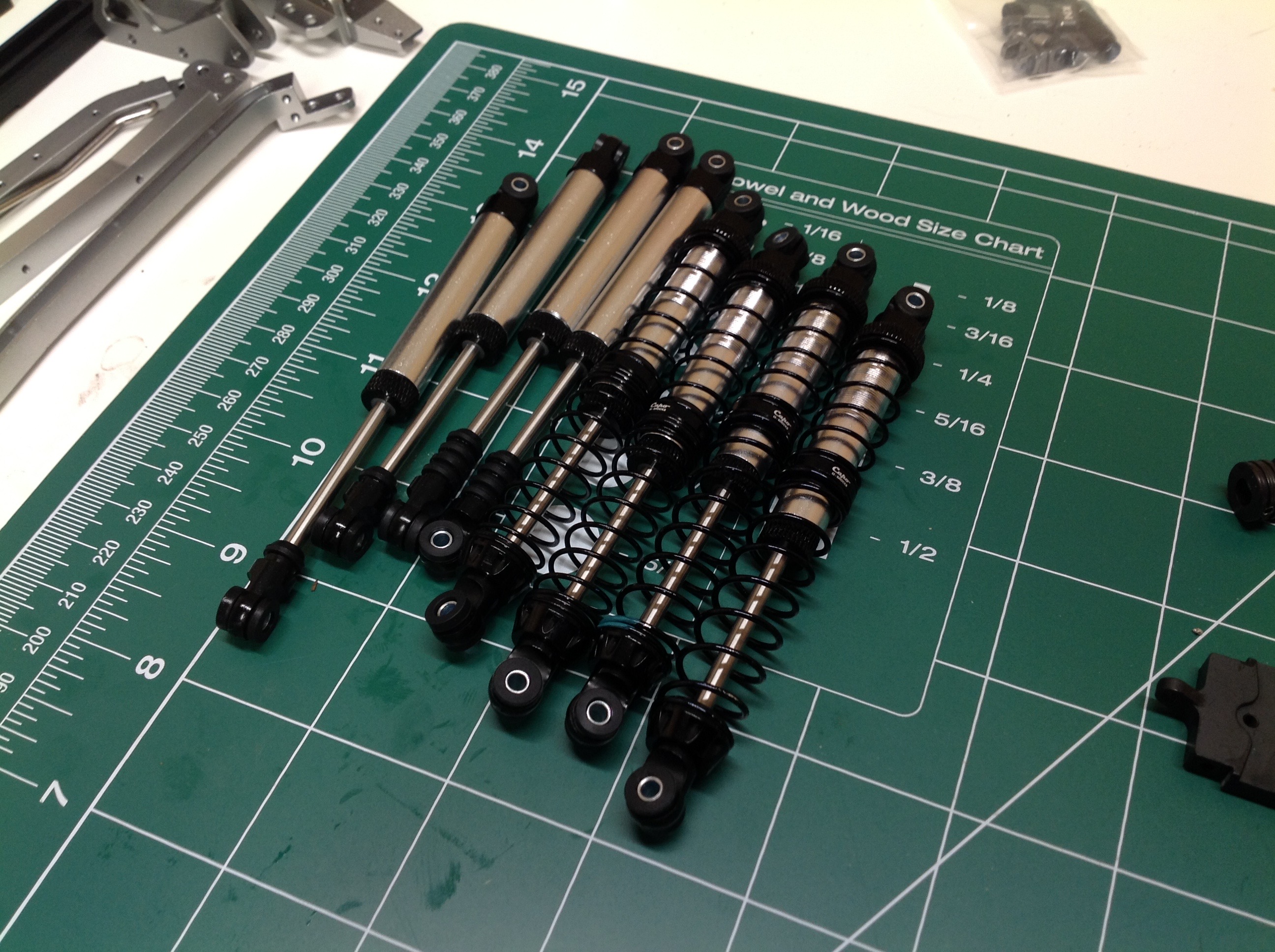
them. There are a total of eight shocks, two on each corner.
Each pair includes both a sprung shock and a pure damper. The
sprung shock has two springs in series with a floating piston in the
middle to allow a progressive rate. The damper has no external
springs.
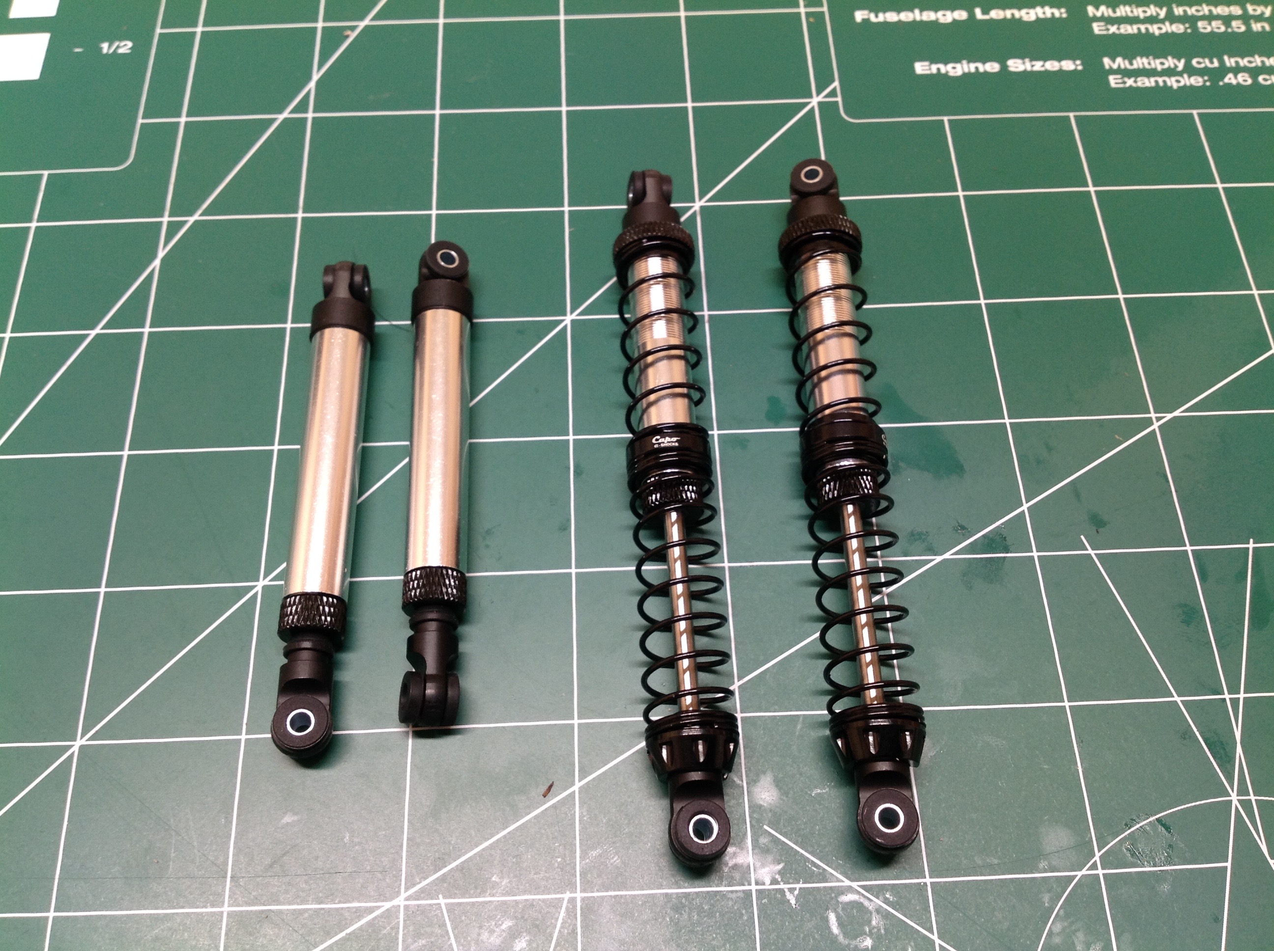
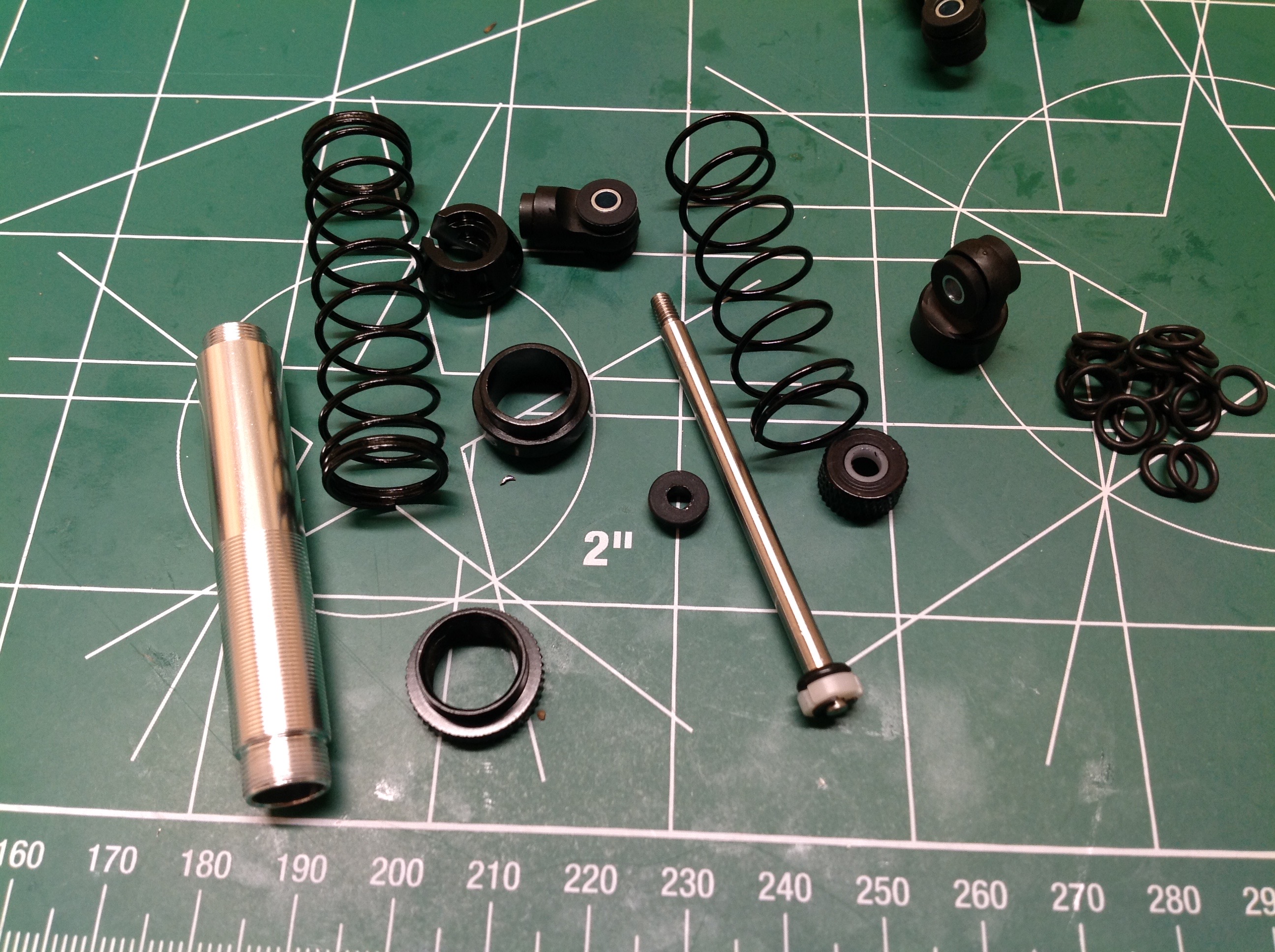
The left hand image shows a damper. There's not really anything to
adjust here, you just need to fill it with oil. On the right you see the sprung shock which
is similar but with external coil springs.
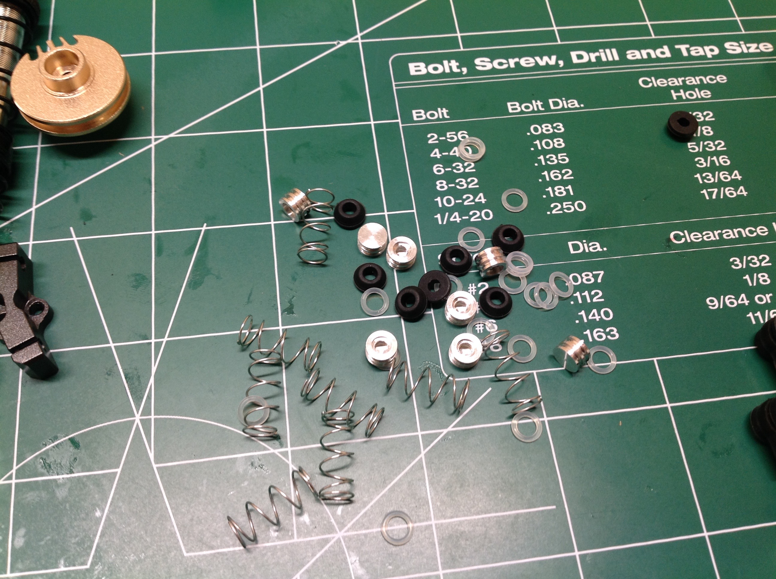
These shocks have an internal floating piston for volume compensation
with a small spring above the piston. You need to be careful not to
overfill or you get an internal lock. Capo sent out a set of the black o-rings shown to replace the white
rings that came in the shocks. I only used the new versions so I
can't say which is better, but the shocks are fairly leaky and quite
sticky. By than I mean it is hard to get them moving if they have
been sitting for a while. Once they break free, they move very
smoothly and their spring rate is just right for this truck.
Despite the apparent pre-assembled shocks, I probably spent 4 hours
getting them right.
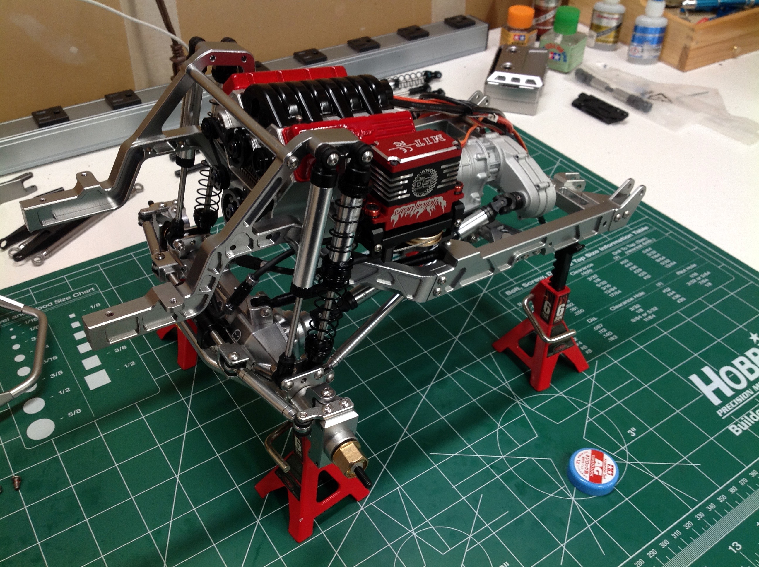
Once the four front shocks are installed it is hard to stop admiring
this thing. It looks absolutely nothing like anything else I've
ever built. Everything is metal and heavy.
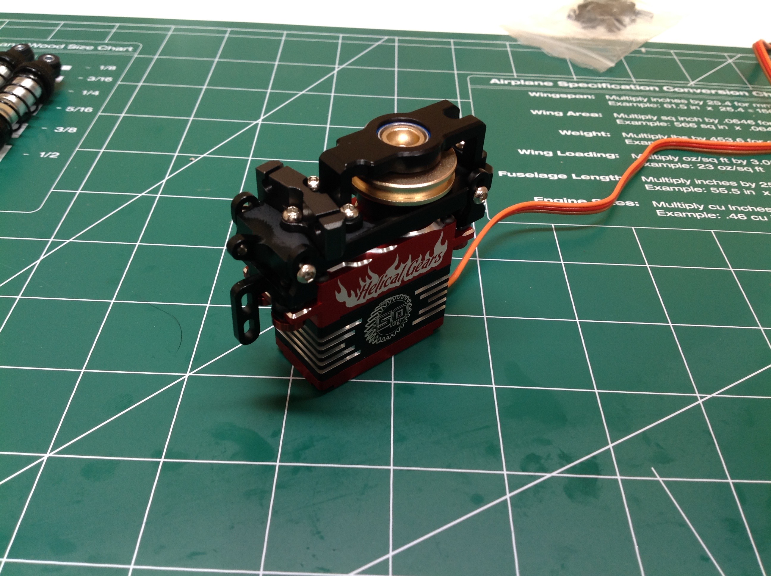
Capo likes to use cable driven steering and this is something I was
worried about because I know people have had trouble with it. With
the heavy vehicle and tires, you need a very capable servo. This
all-metal unit from Blue Bird has 50 kg-cm (800 oz-in) of torque, by far
the most I've ever seen, so it seemed like a good choice. I also
liked that the red would fit with my color scheme. You build a
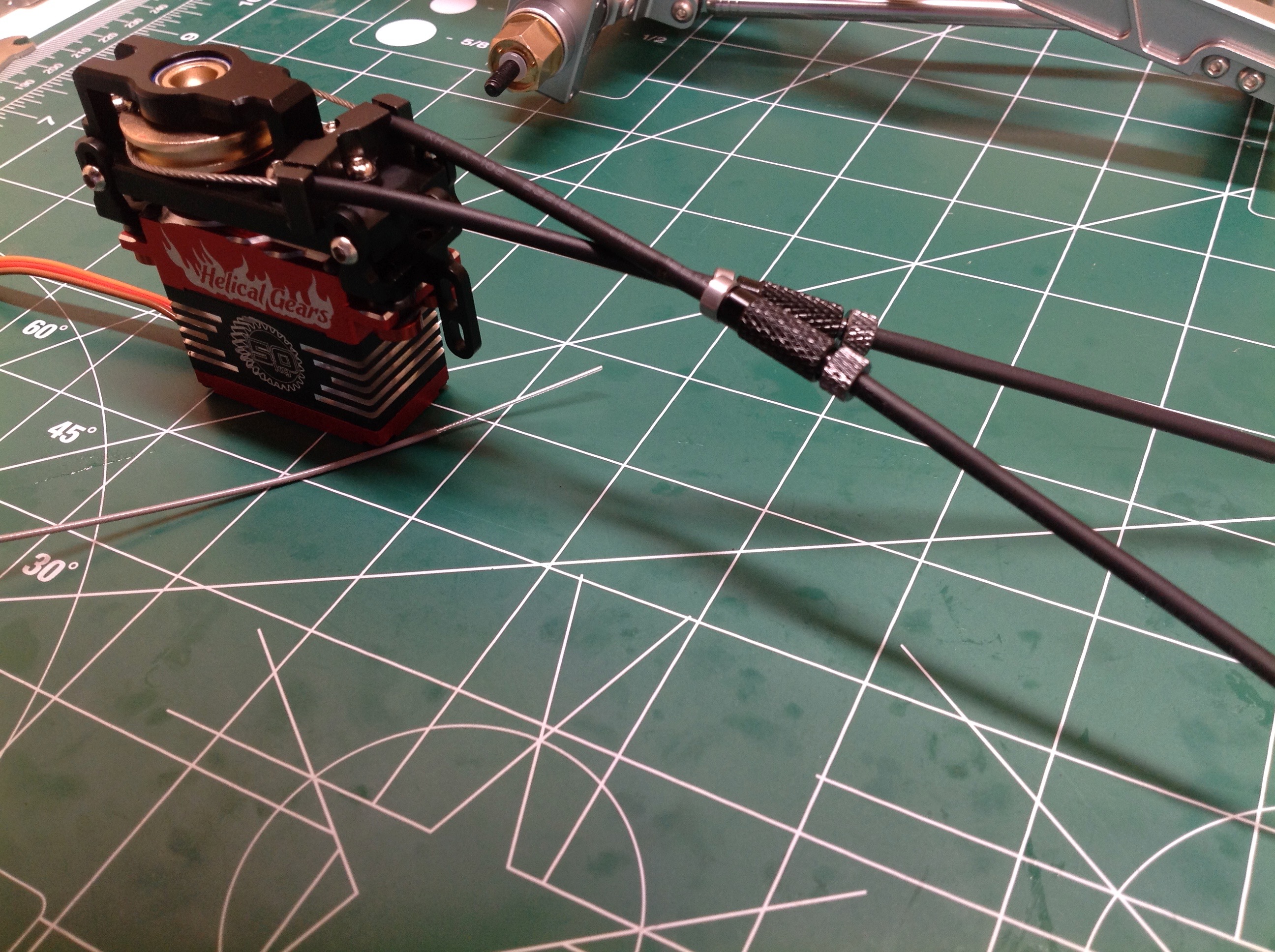
large metal enclosure over the top of the servo that houses the brass
pulley. The cable is then locked to the pulley and routed through a
set of cable sleeves. Those bits you see in the middle are
tensioners which are used to stretch the cable once installed.
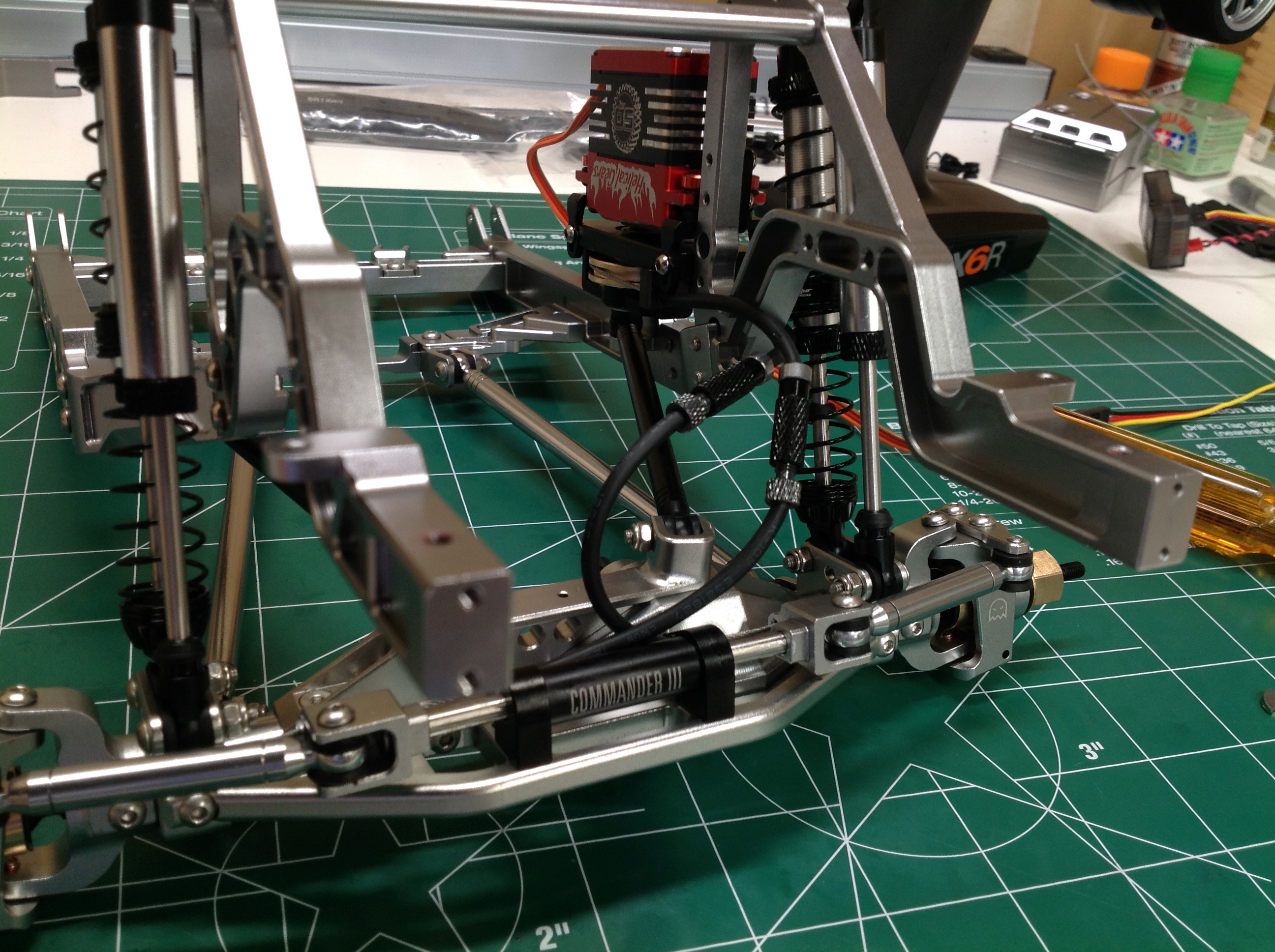
Now the servo has been installed in the chassis. The ends of the
cables attach to the steering stabilizer at either end which allows them
to pull the steering in either direction. This is a pull-pull
system (a closed loop) so you are never pushing on a cable. I
needn't have worried about the steering. Once I got the cables
tensioned properly this thing has been trouble free. It has
the huge scale advantage of getting the steering servo completely out of
sight.
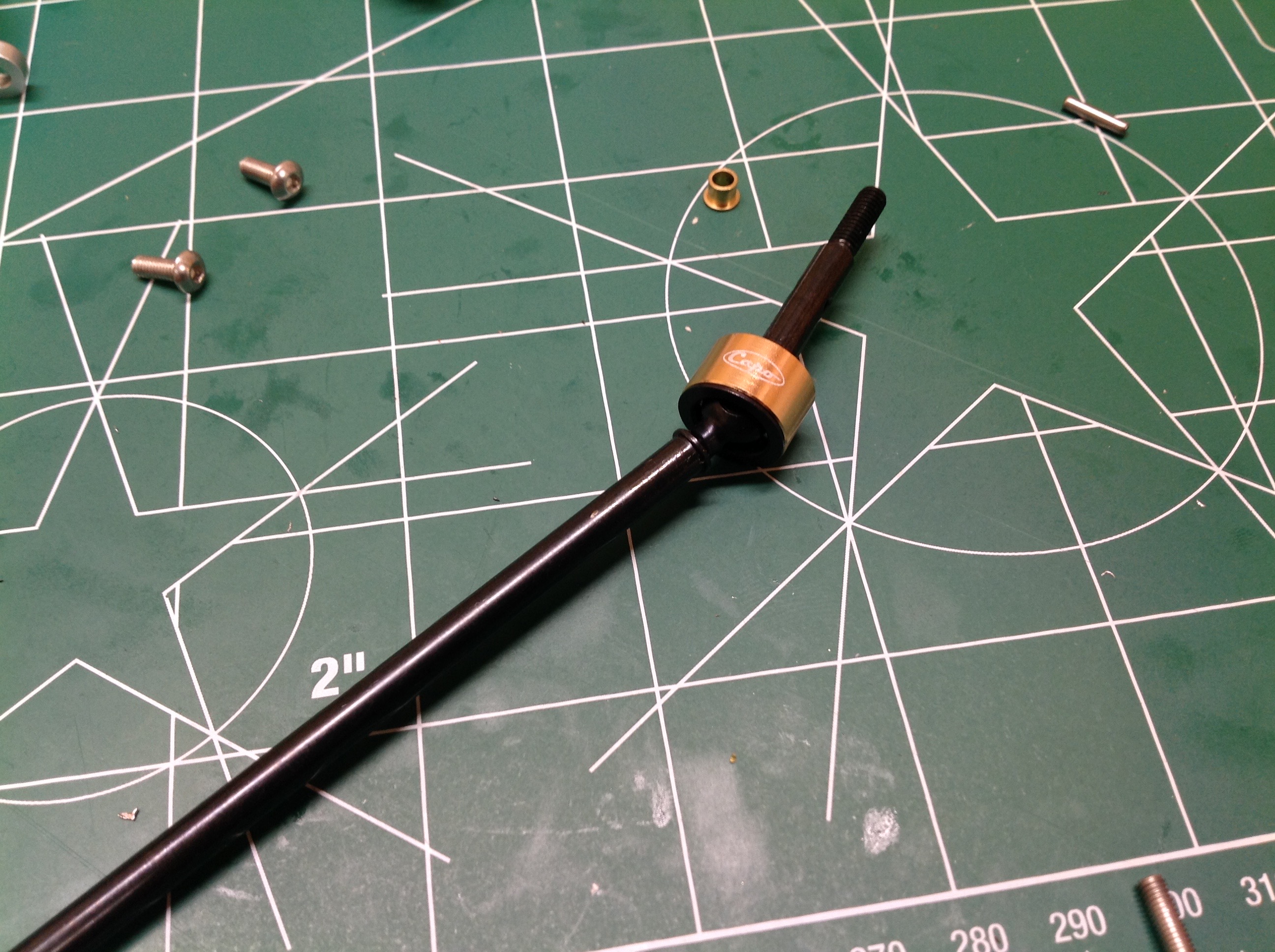
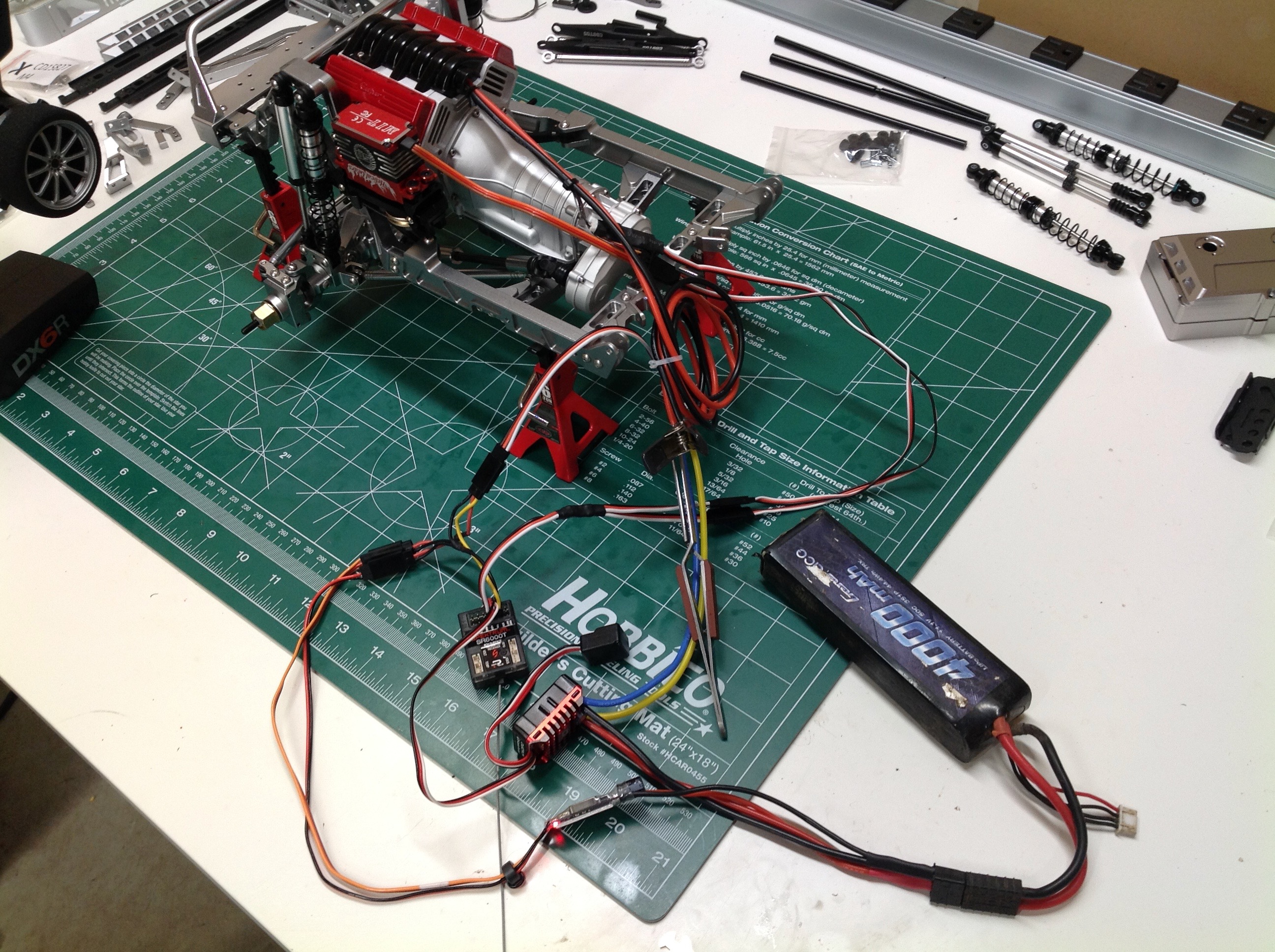
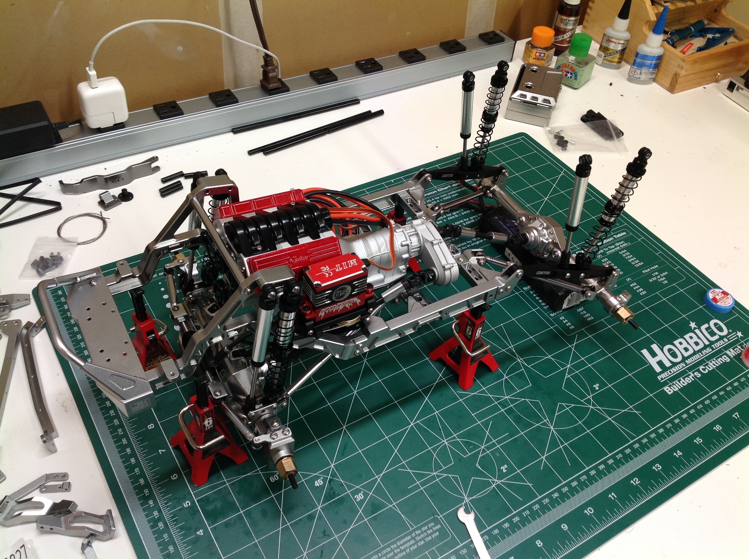
With the steering done we can now install the engine. This is just
a matter or dropping it in and screwing it down. The front drive
shaft must also be installed at this time. Although it is not time
to do the electronics yet, since the front is mechanically complete
there was nothing preventing me from cobbling the wires together and
firing up the motor. It was good to see how everything works,
check the shifting in the transmission, and make sure the steering was
working properly and free from binding or slop.
The rear axle is a simpler version of the front. It still has a
locked spool and 4-link connections but no steering
accommodations. The upper links are a lot different though.
Instead of being plain rods they are profiled tubs into which the rear
shocks can attach. The rear driveshaft is also installed. At
this point the whole rear assembly just flops around because it has no
upper attachment.
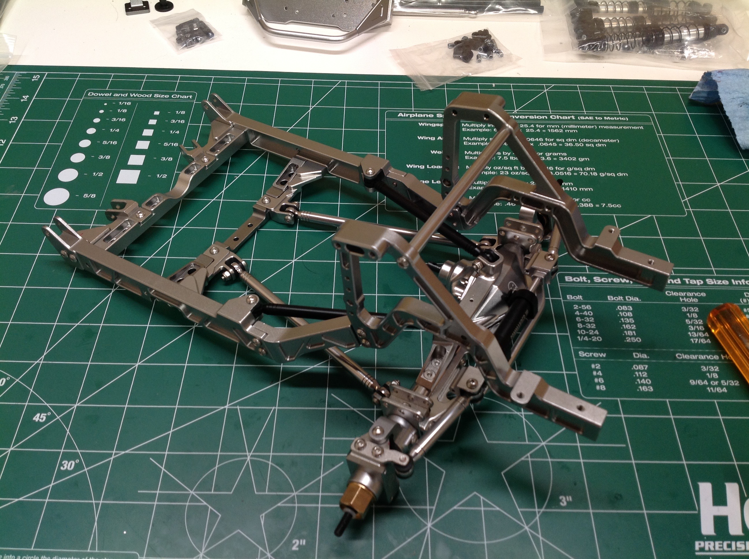
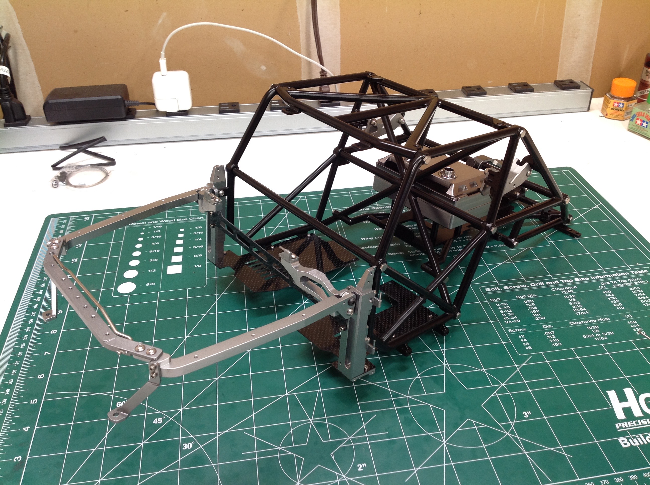
The four rear shocks connect into the upper links and then the frame is
done. But wait, isn't something missing? Yes, this is not a
self-contained frame. The cage will become an integral structural
part of the chassis to which the rear shocks will attach. That
right hand picture might be my favorite.
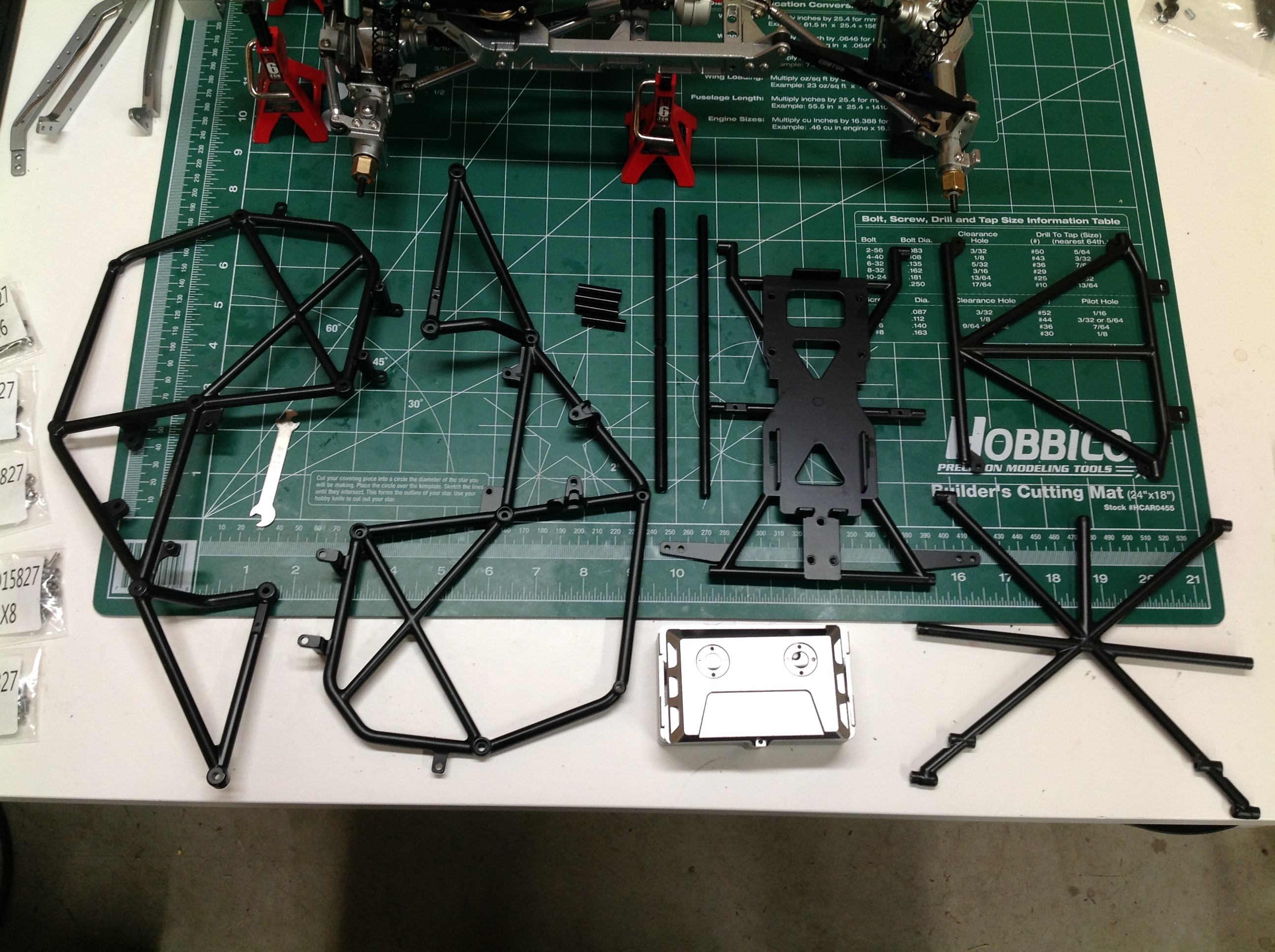
The cage is made from welded tube assemblies which have apparently been
powder coated. These are seriously thick, heavy, and strong.
In a way this can be a problem because if anything doesn't line up
properly it will not bend into position. It is important to get
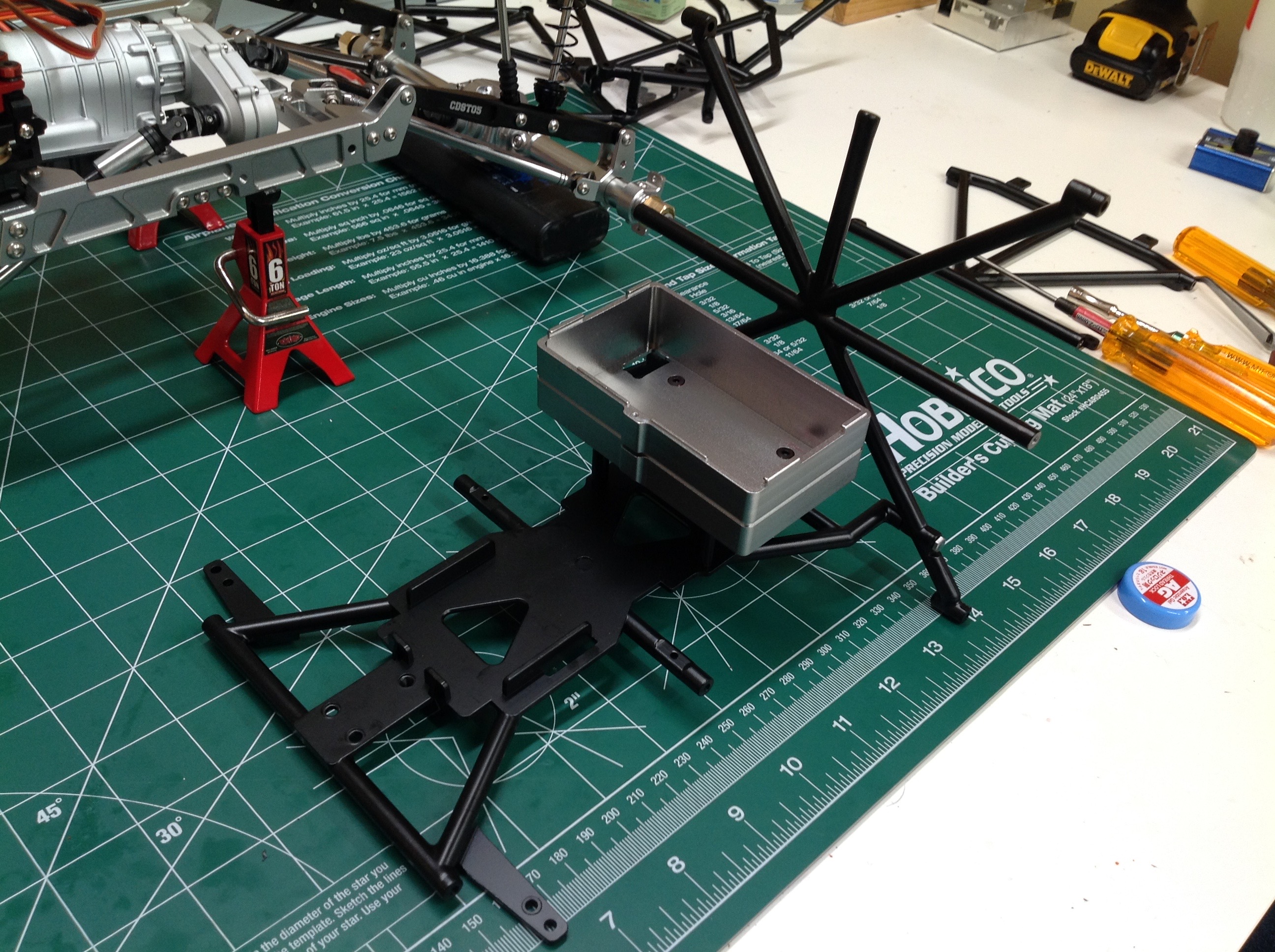
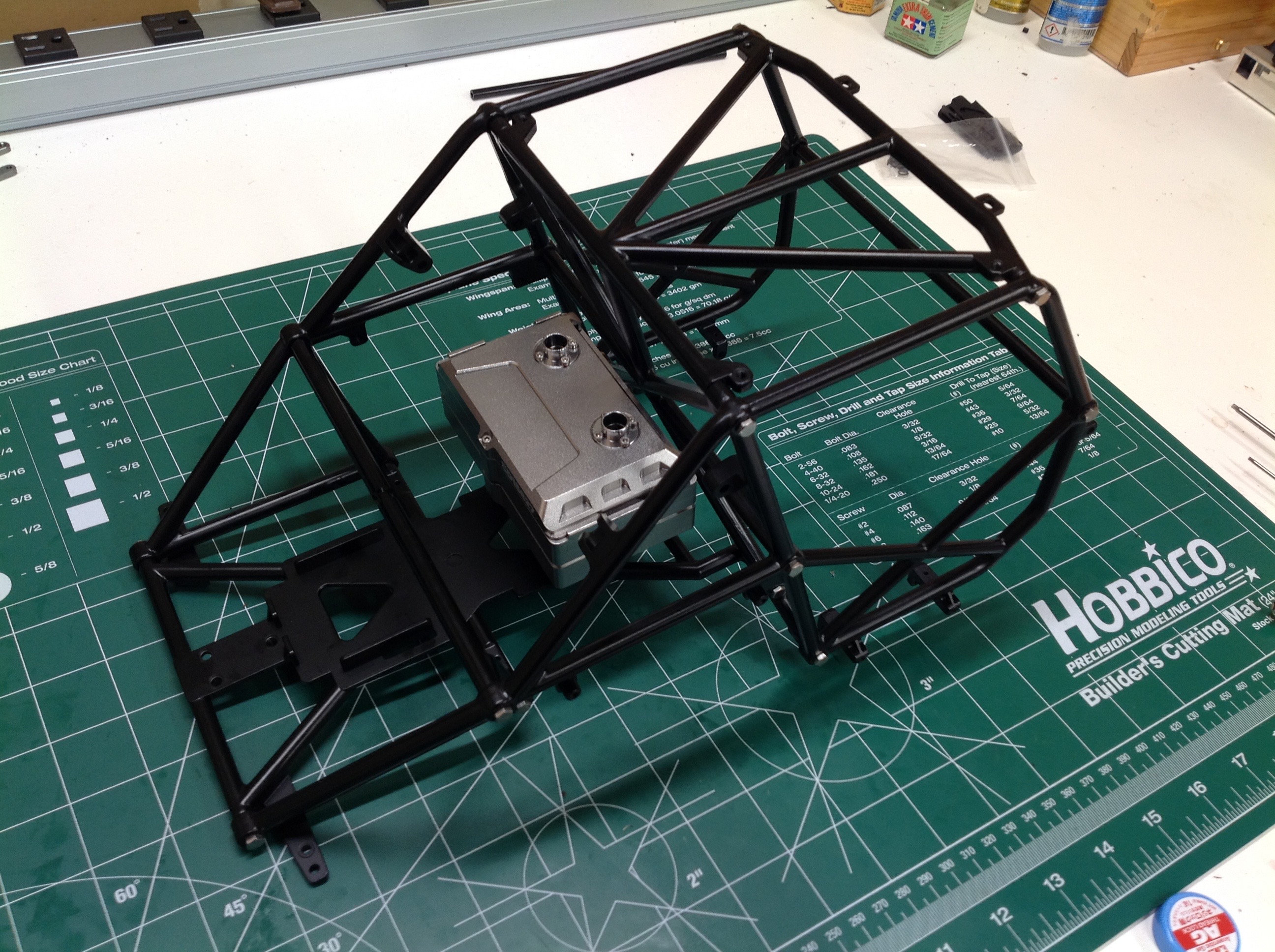
all the screws started before you tighten anything. The right hand
image shows the bottom plate, the rear cross, and the aluminum
electronics box (which looks like a fuel cell). The plate under
the box is where the battery goes.
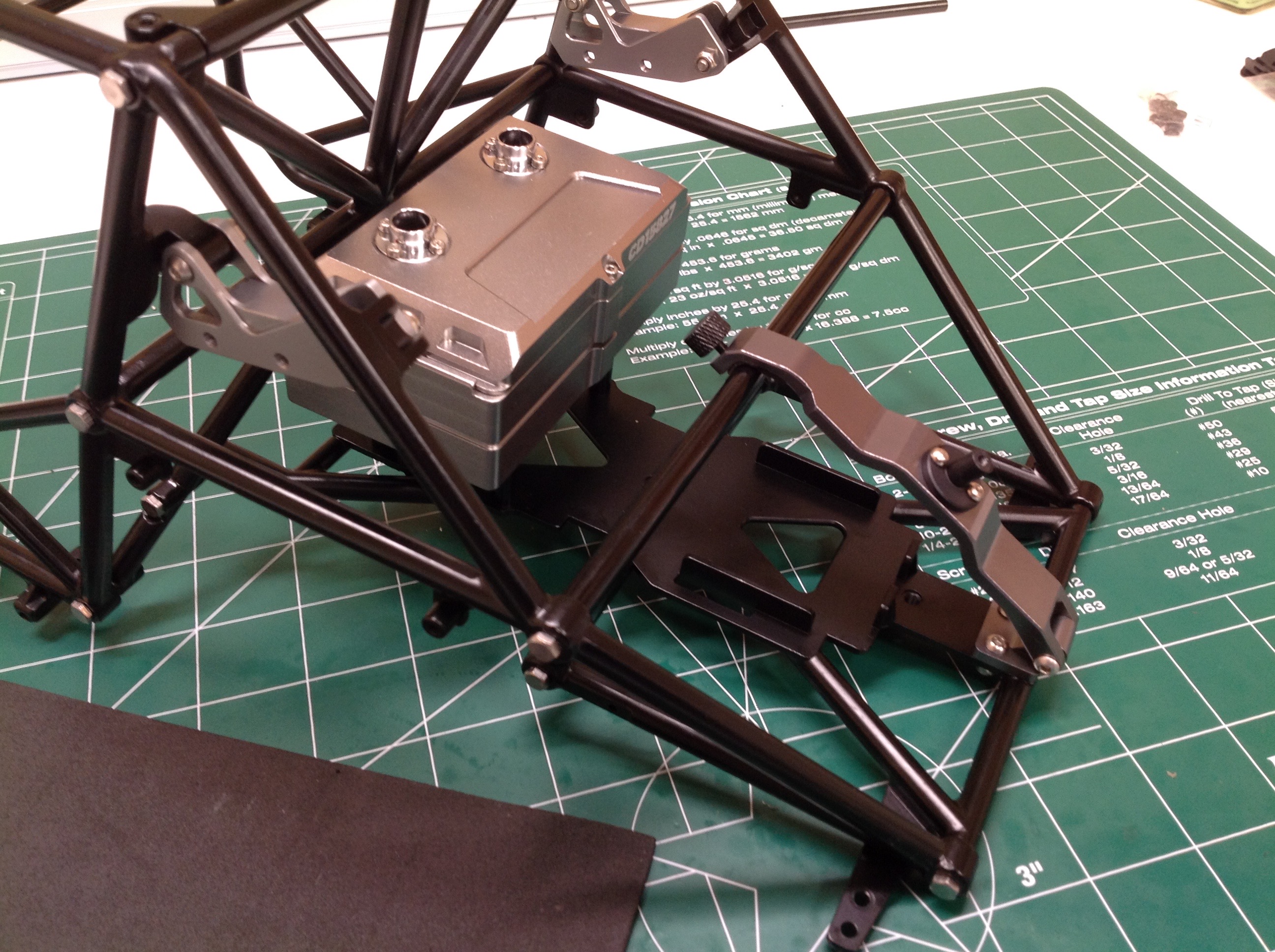
The completed cage is a beast. Note that the hardware is not just
cap screws. Capo used hex bolts because these will be visible and
hex is much more scale. That bracket you see in the back is for
the spare tire. The rear upper shock mounts are integrated into
the cage.
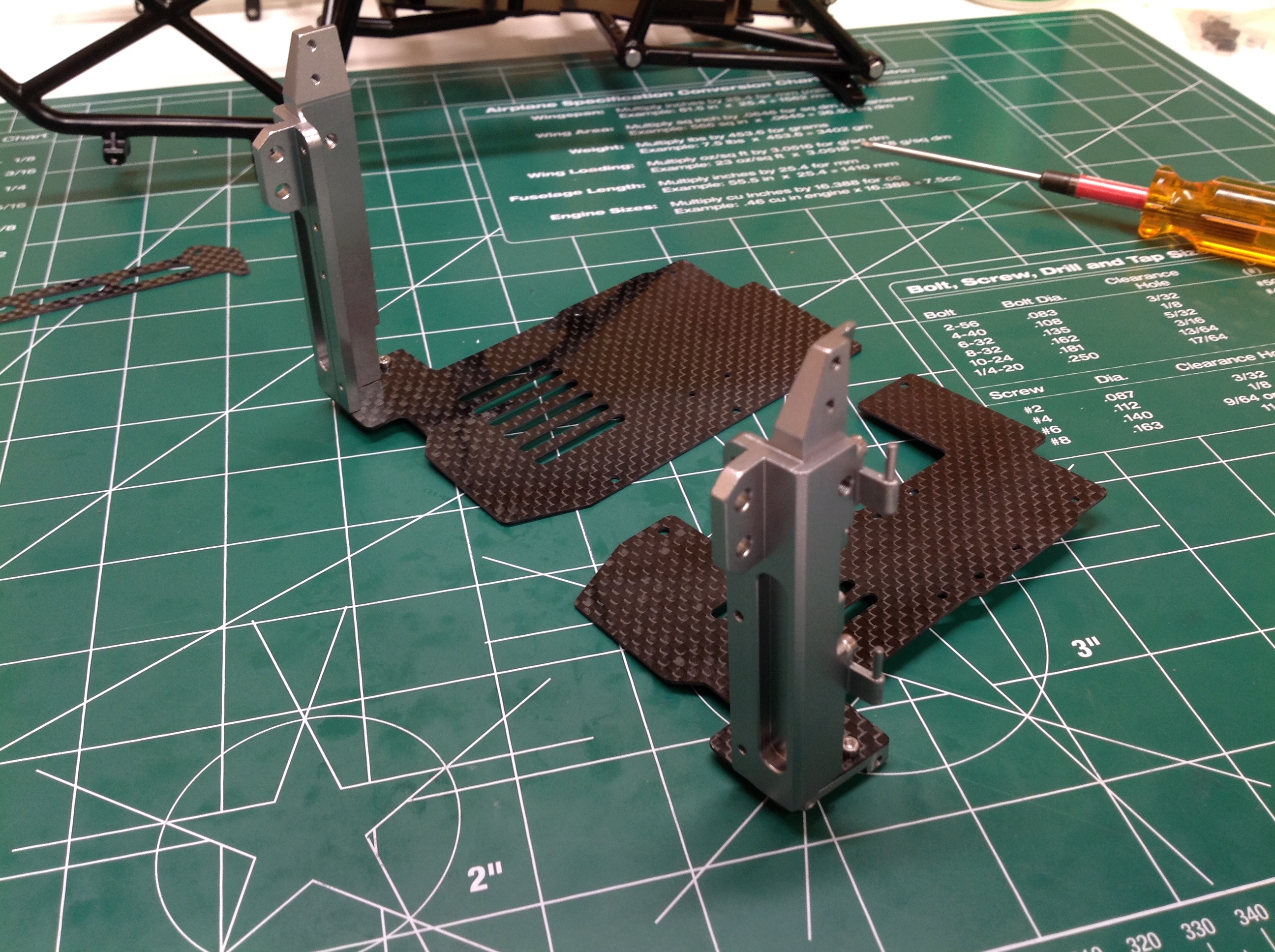
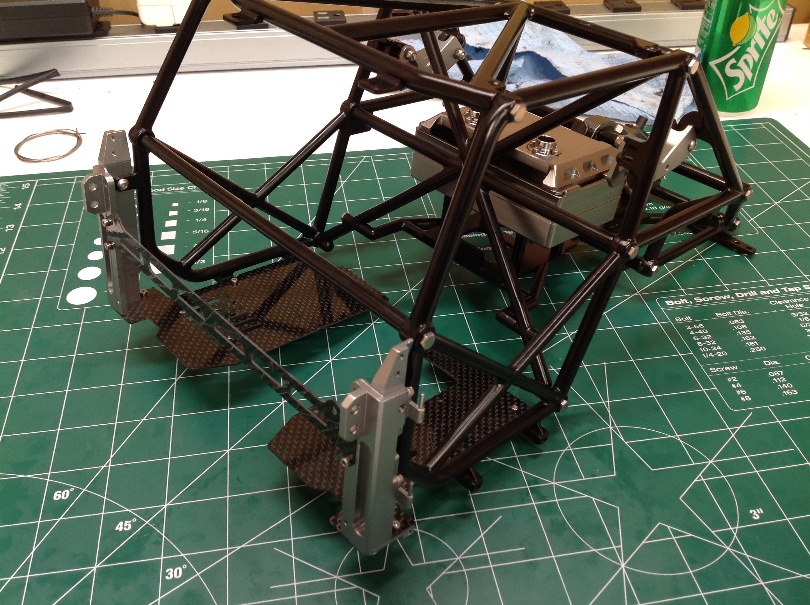
The floor of the cabin doesn't really serve any structural function so
it could have been made of anything. Capo therefore decided to use
carbon fiber sheet! Completely unnecessary but awesome. The
vertical pillars attached to the floor pans will support the door
hinges.
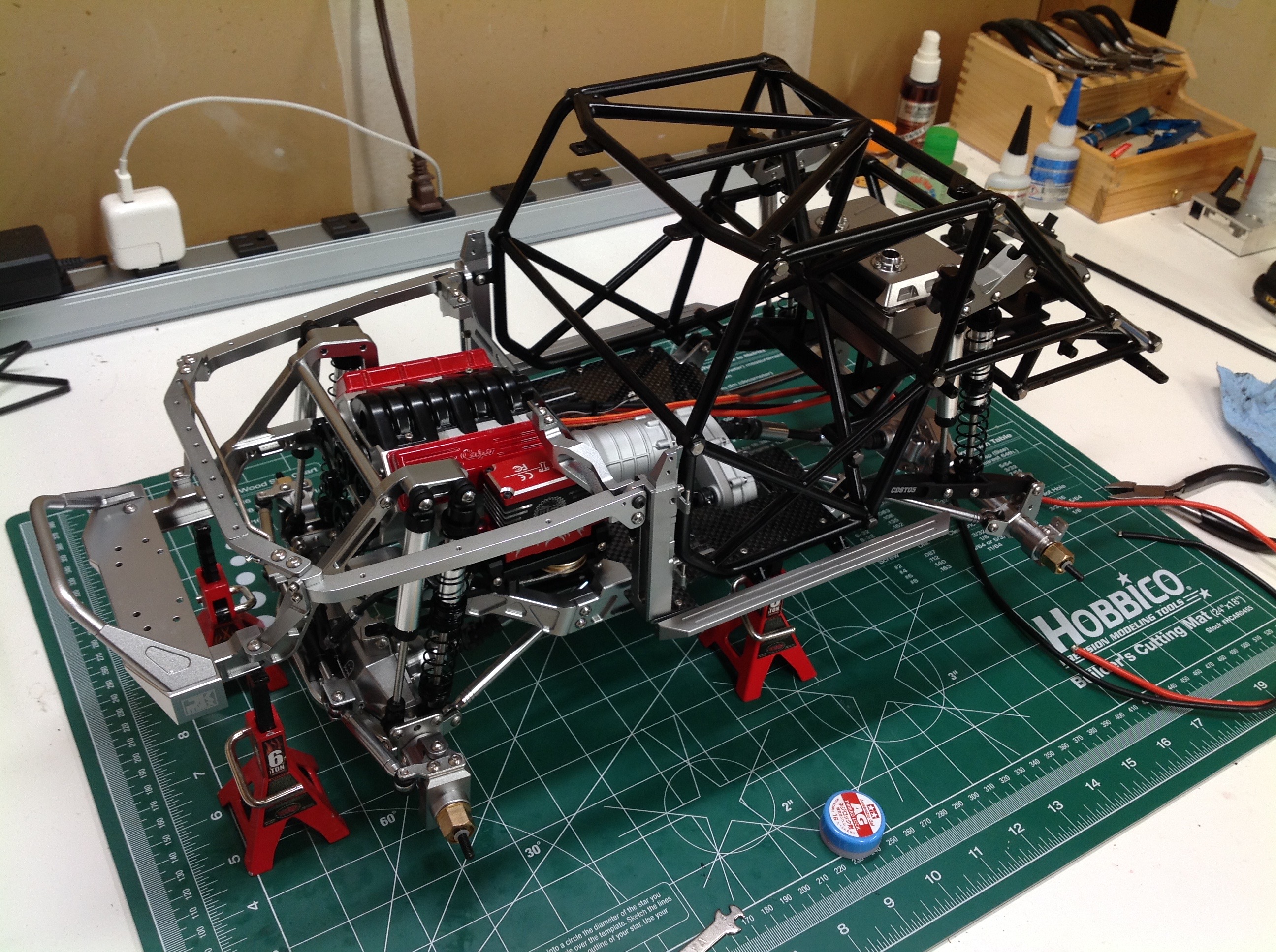
Next up is the frame around the engine bay. These bits serve to
support the hood and grille but also to stiffen the entire chassis
because they serve to link the cage to the forward frame. In the
right hand image both large sub-assemblies have been married
together. Now the full structure of the vehicle is complete.
Everything else is just cosmetic.
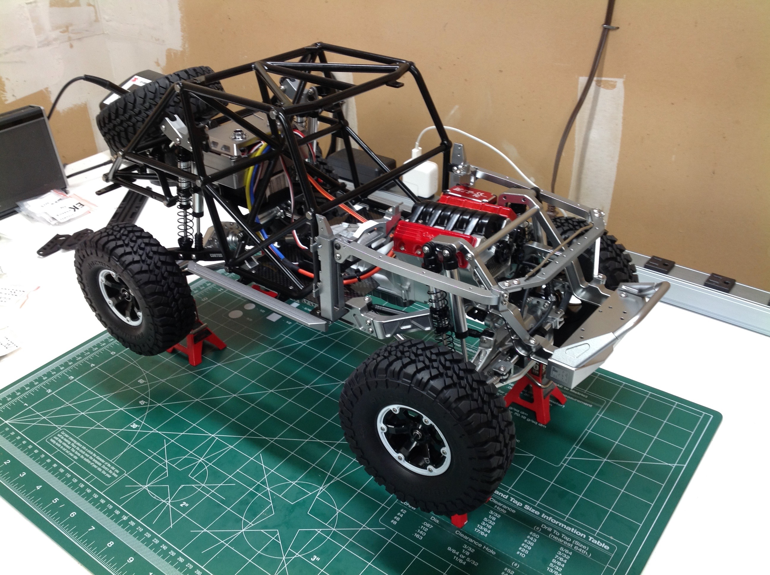
I always get a rolling chassis running before I bother with the
body. In this case that means attaching the tires and then wiring
everything up. I didn't need to do the complete wiring job just to
try it out.
©2018 Eric Albrecht