Kyosho Javelin Project
Page 1: Stock Assembly
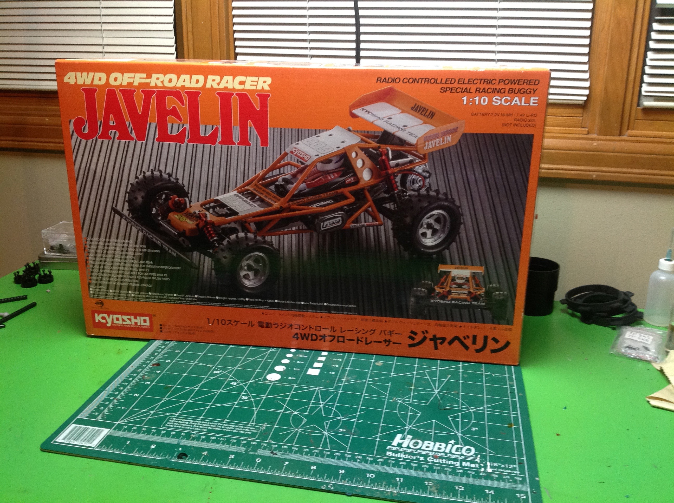
The box is quite classic looking with a photograph that appears old (but
is actually new) along with period lettering and art. Inside the
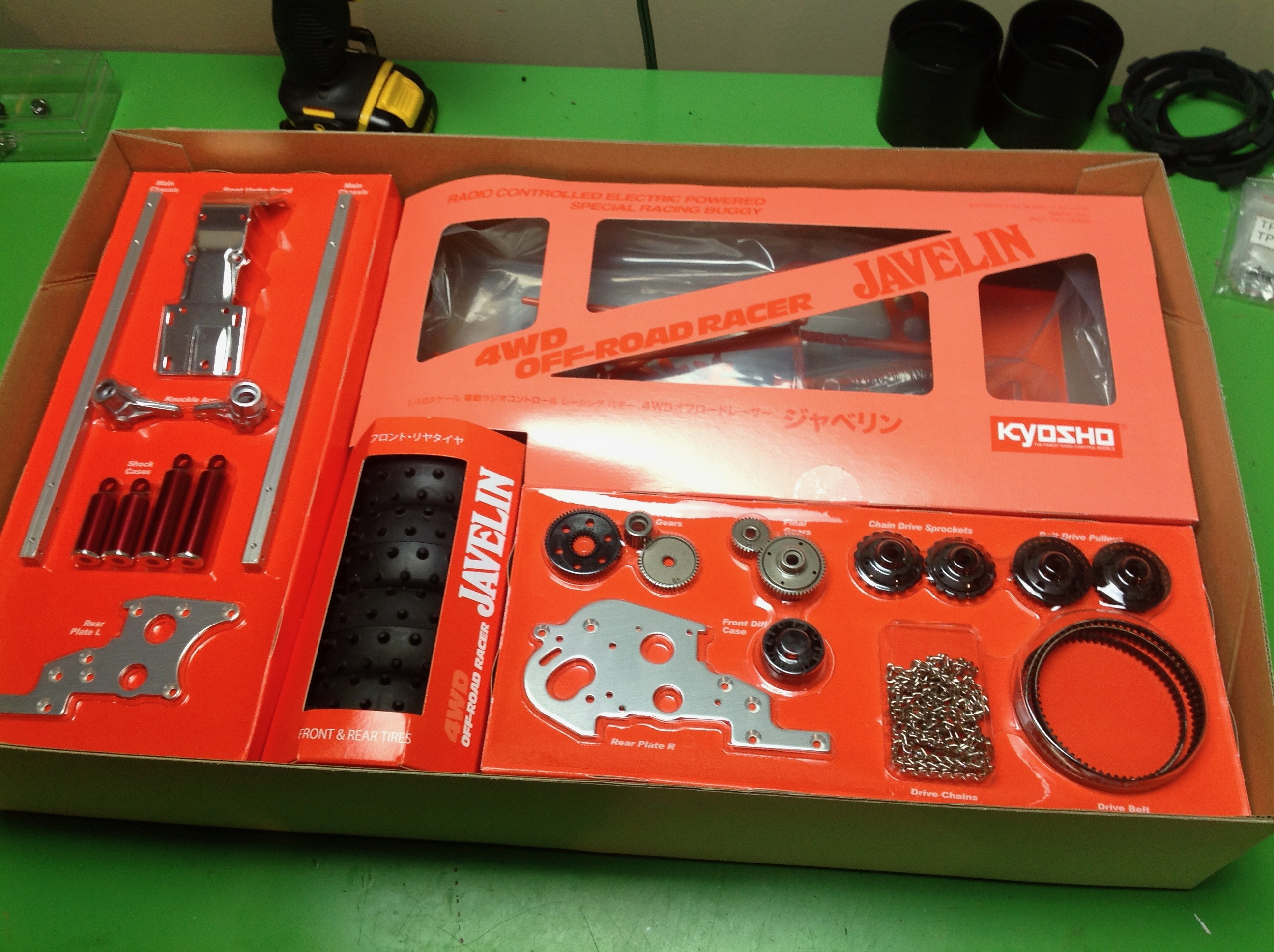
box you'll find a couple of blister packs displaying the more remarkable
parts in the set as well as a slotted box displaying the tires.
The right hand lower blister contains both the original chain and the
optional belt.
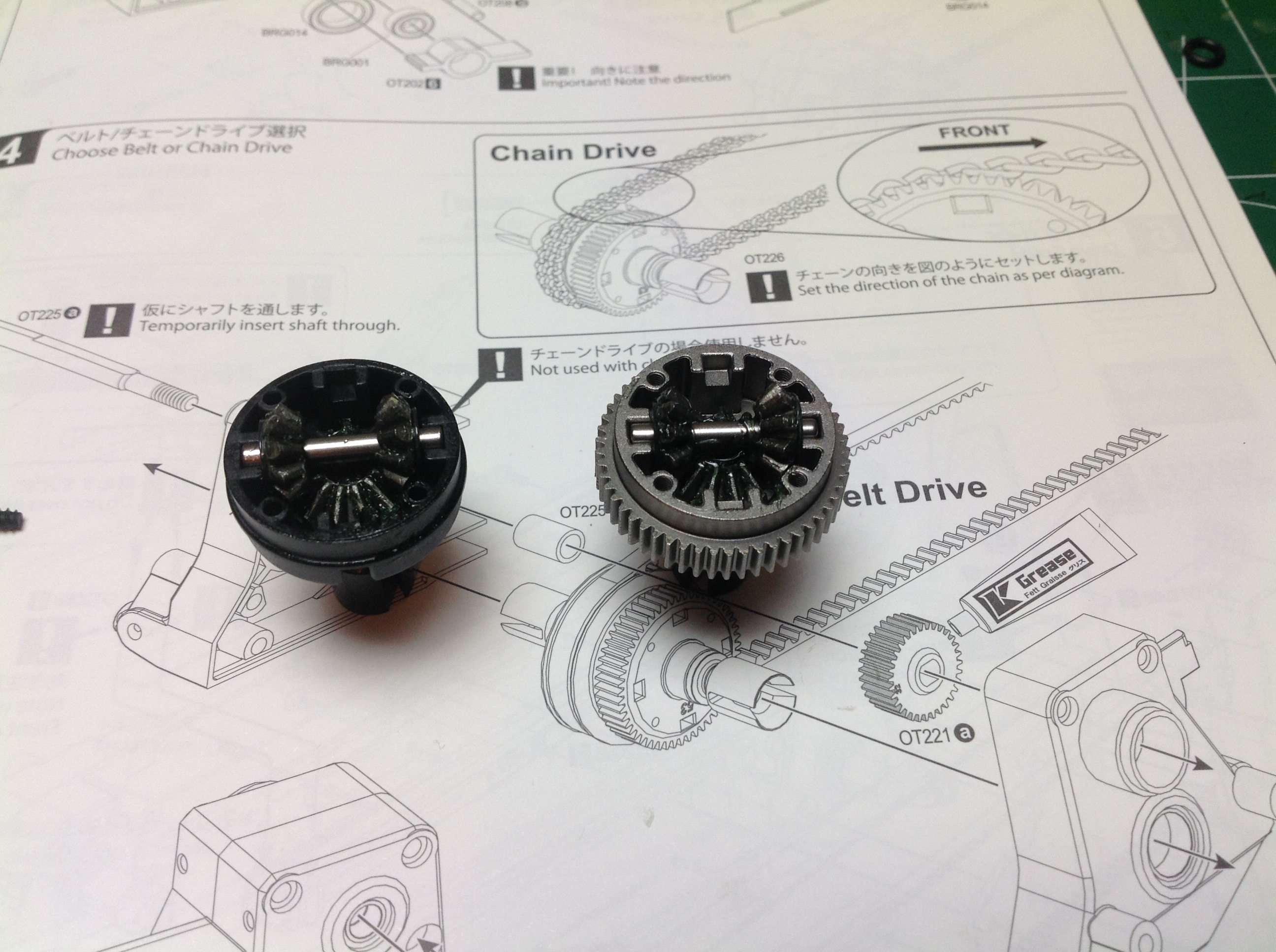
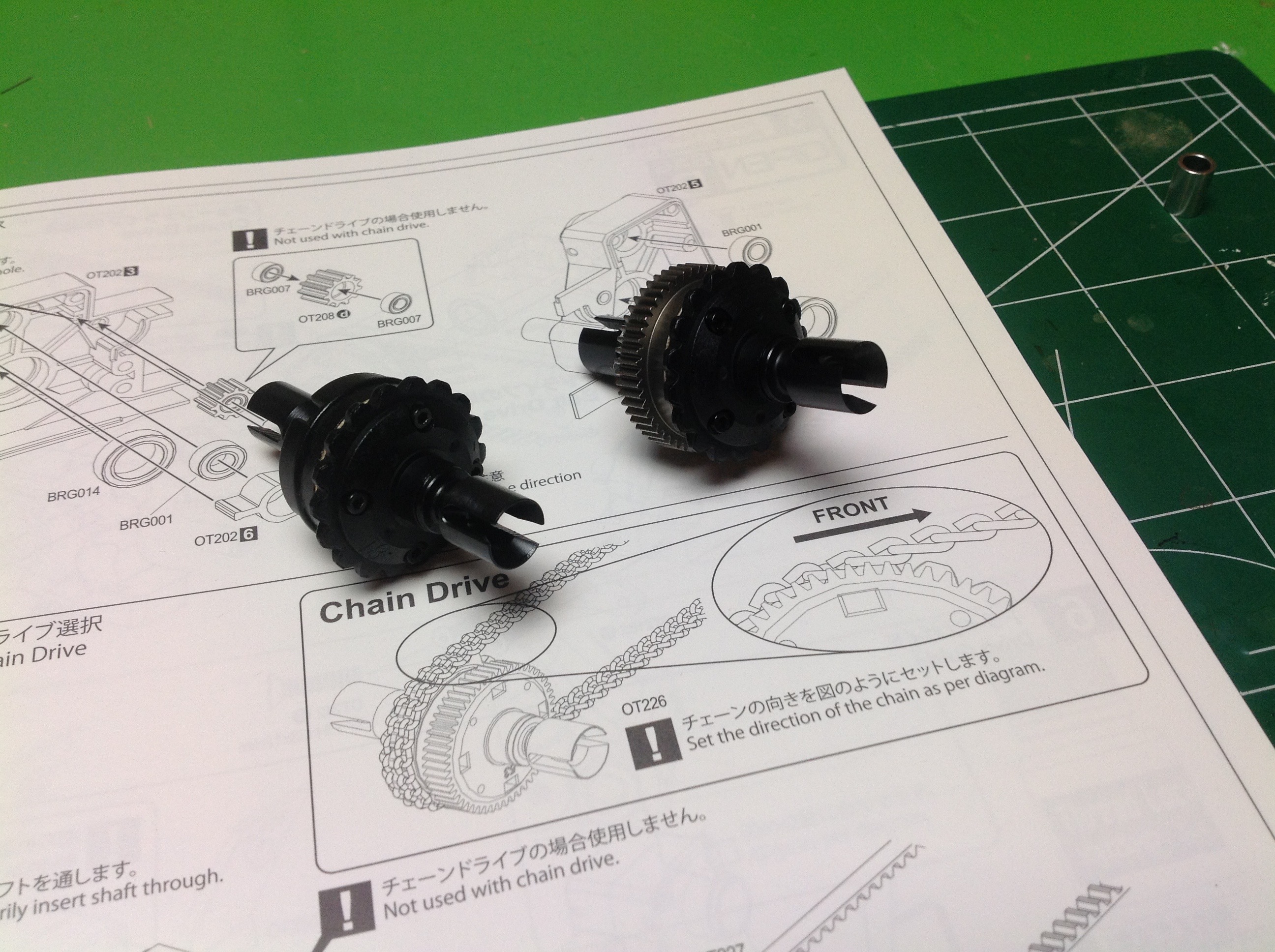
Construction begins with assembly of the open gear differentials.
Both front and rear contain a sprocket for the chain (if you are
building with that option), but the rear also adds a spur gear.
These are sealed differentials, but they are not filled with oil.
Instead you apply grease included with the kit per the instructions.
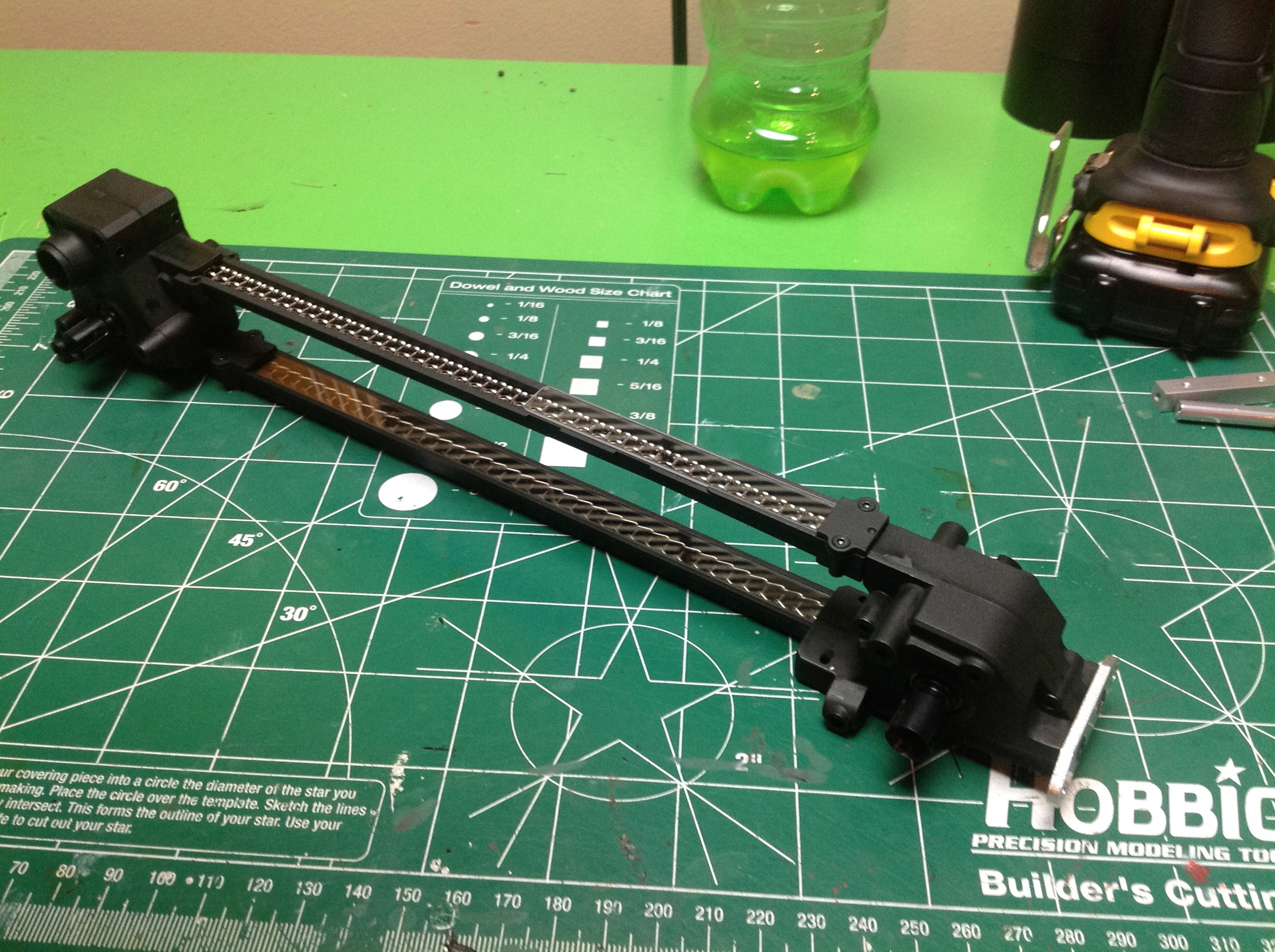
The left hand image shows the installation of the rear differential in
its bulkhead. The chain must be wrapped at this time since it will
not be accessible later. The transmission drive gear is also
installed here. The right hand image shows the unusual structural
arrangement of the chassis. Rather than having a flat, solid base
plate, this model makes a structural core from the drive system.
The chain is enclosed in a longitudinal tunnel with viewing windows so
the splendor of the chain is not hidden.
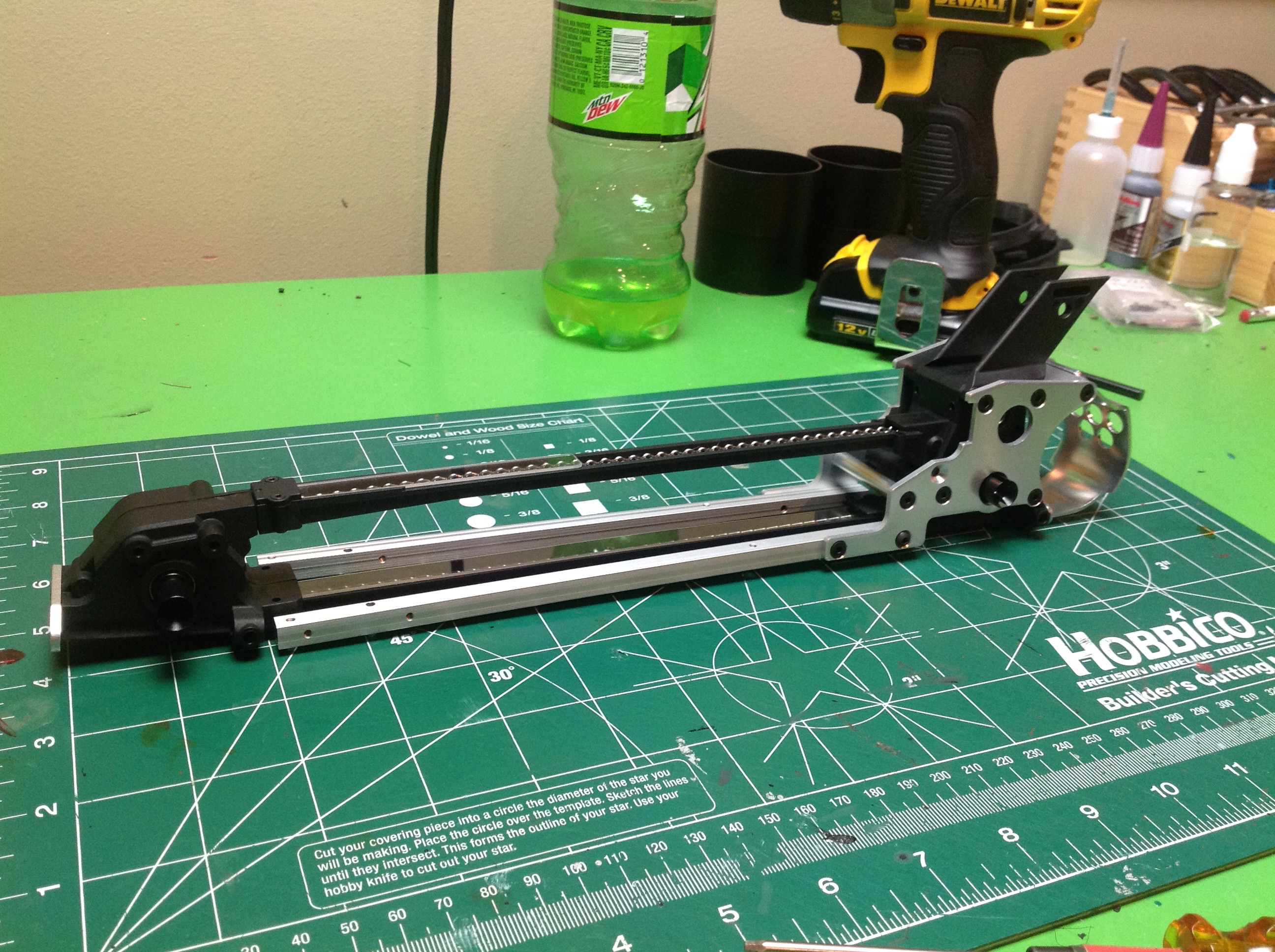
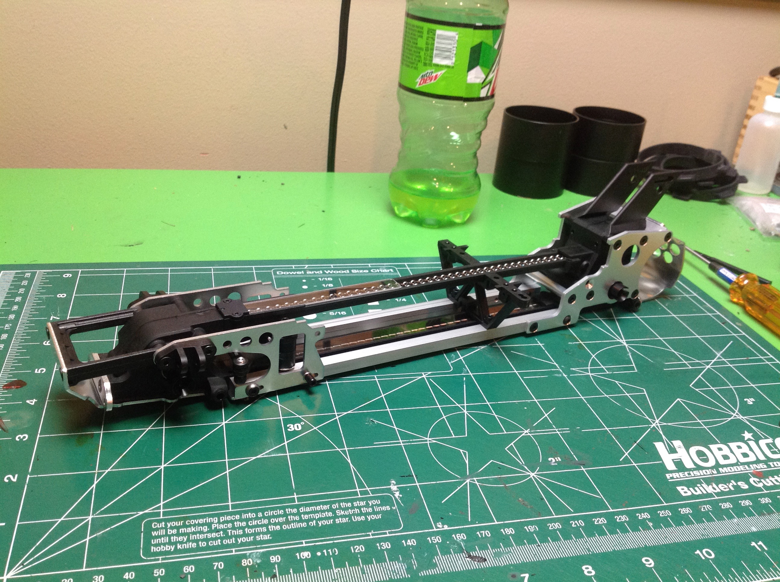
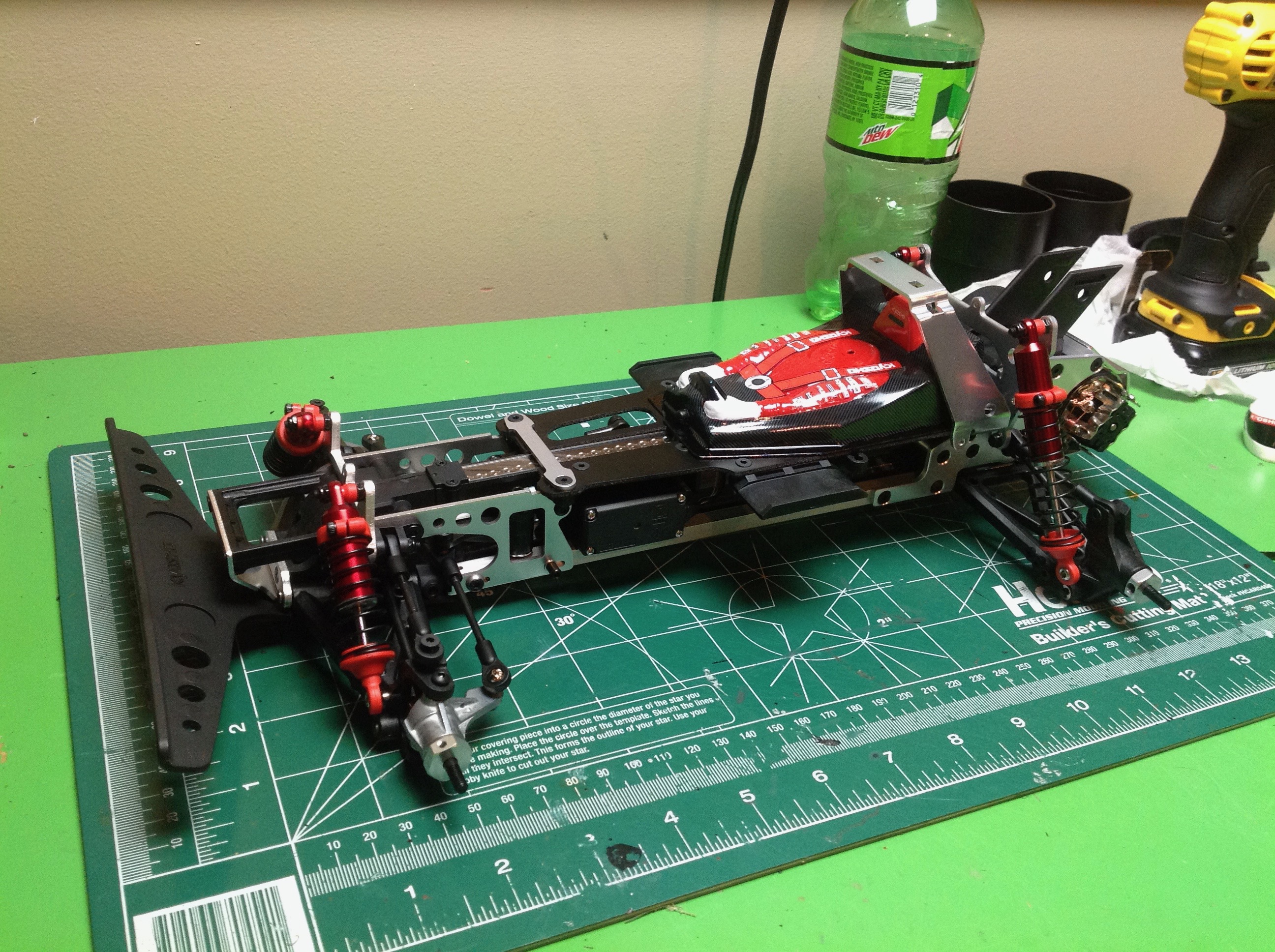
The central core is now strengthened with extruded aluminum rails
affixed along the bottom. The fins seen on the top of the rear
bulkhead will be used to support the wing. The right hand image
shows additional vertical stiffeners and aluminum side plates which lock
everything into a very rigid assembly.
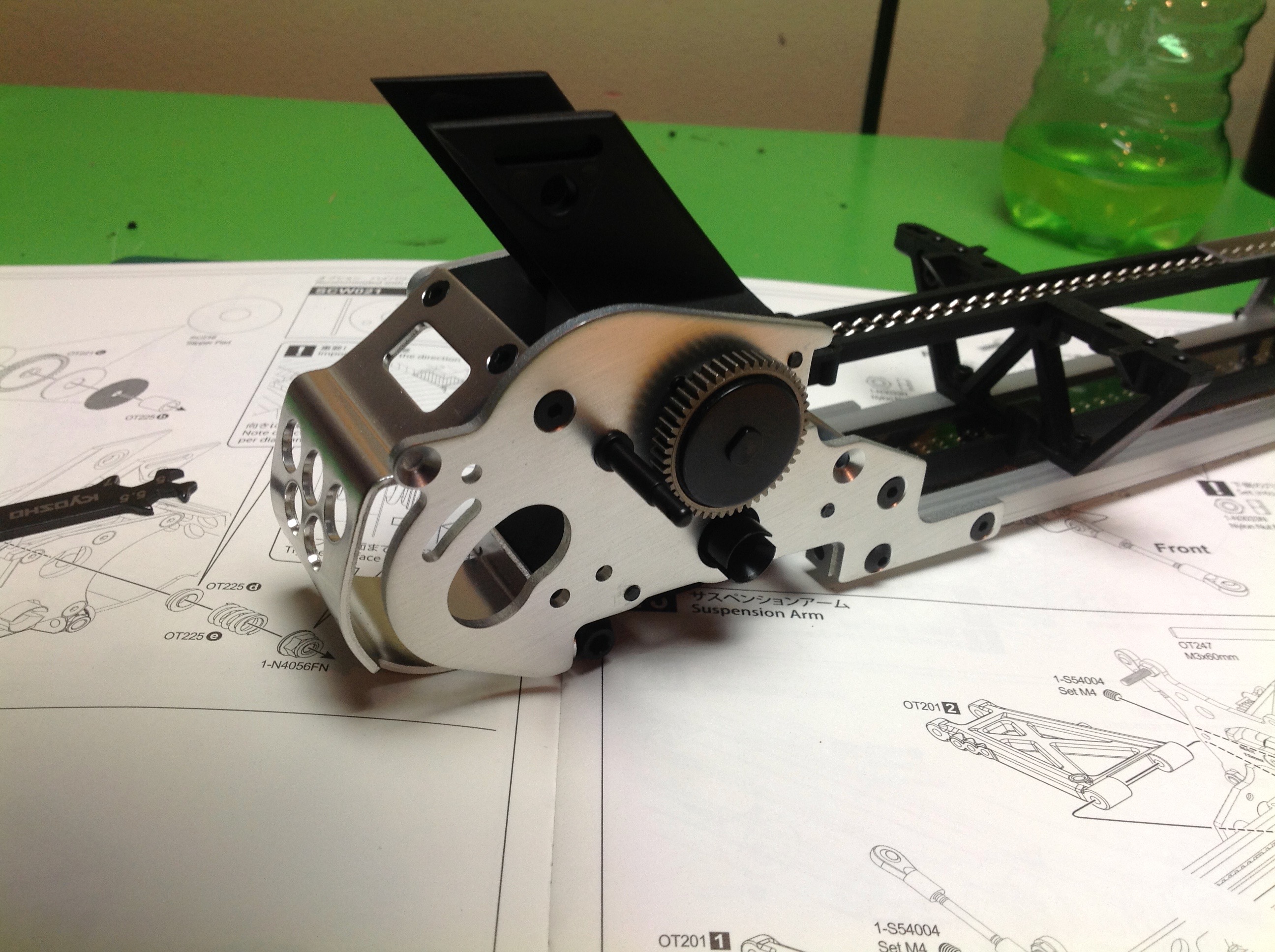
The upper gear shaft of the transmission connects to an external slipper clutch which houses a metal gear as shown.
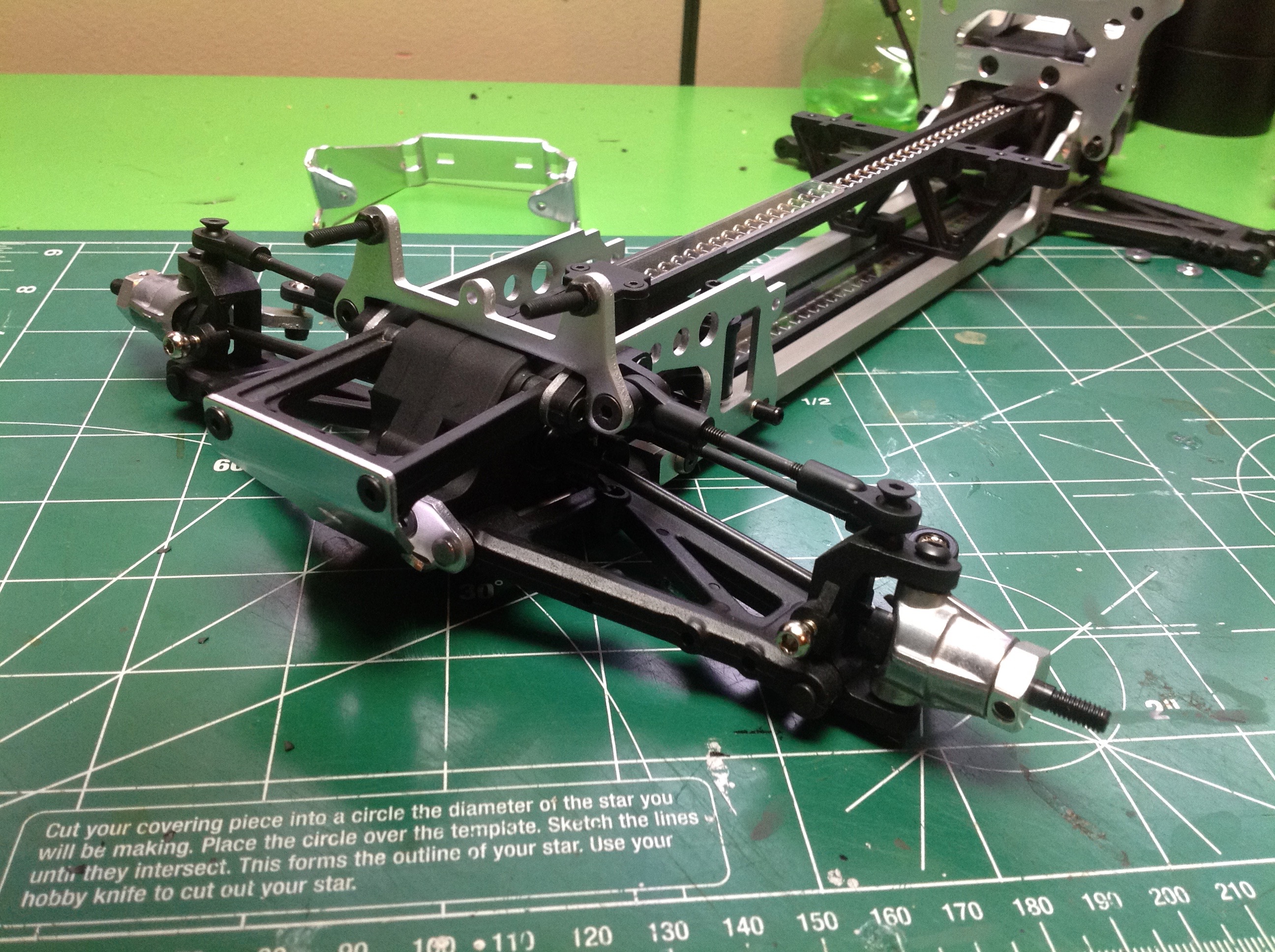
Time to build the suspension. Both front (left) and rear (right)
are double wishbone type independent suspension with adjustable upper
rods. Steering uses C-hubs and aluminum knuckles. The drive
system uses dog bones on all four axles.
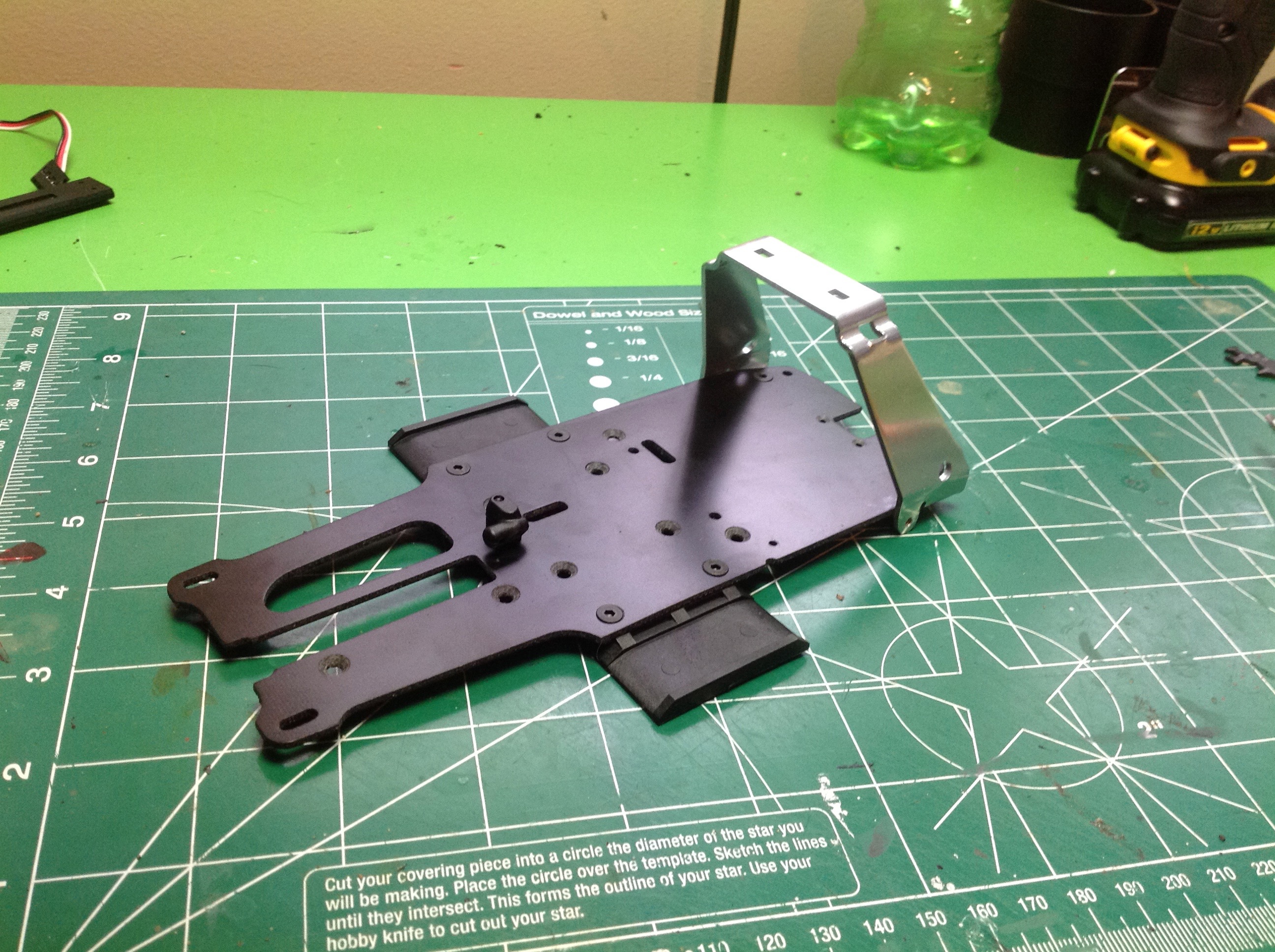
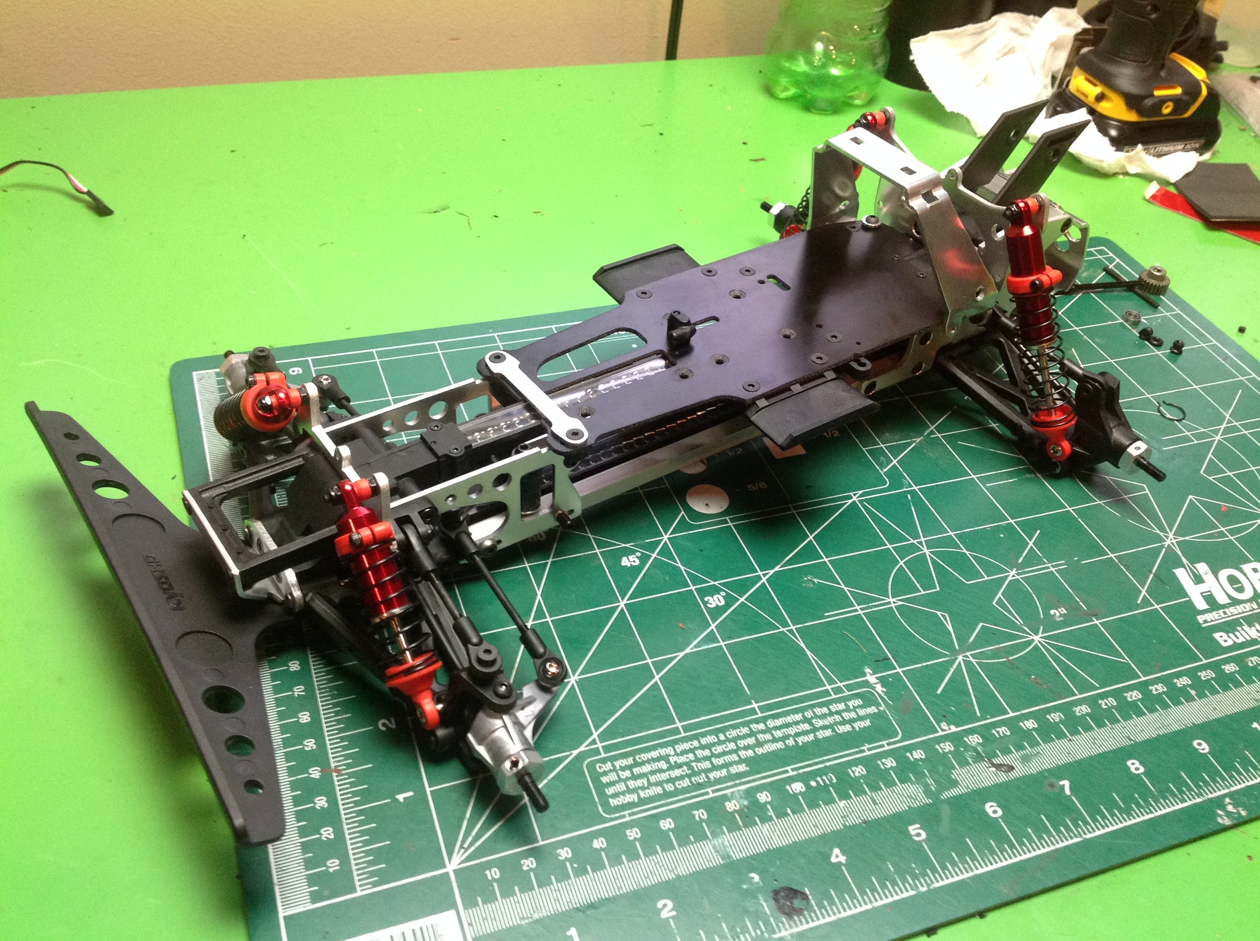
To further stiffen the chassis, a fiberglass plate is added to the top
of the rails. This will provide a stable platform for the
electronics and hide the battery which attaches laterally beneath.
A thick aluminum bar provides rollover protection. Every
direction of this assembly has been thoroughly braced for maximum
rigidity.
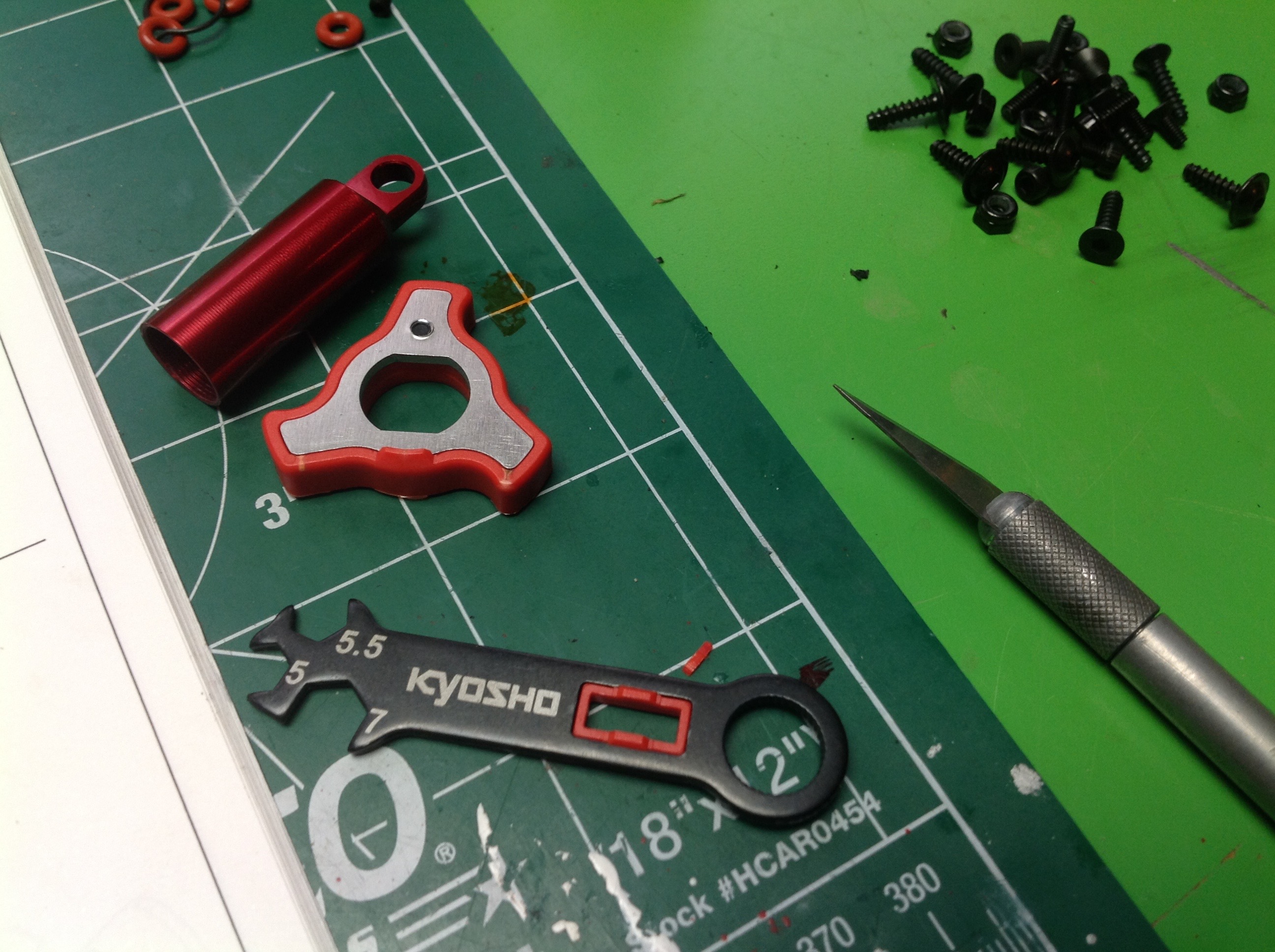
The kit includes a couple of tools custom made for assembling and
adjusting the shocks. The wrench has a slot which fits of the rod
ends of the shock, and the 3-bladed star acts as a wrench for the end
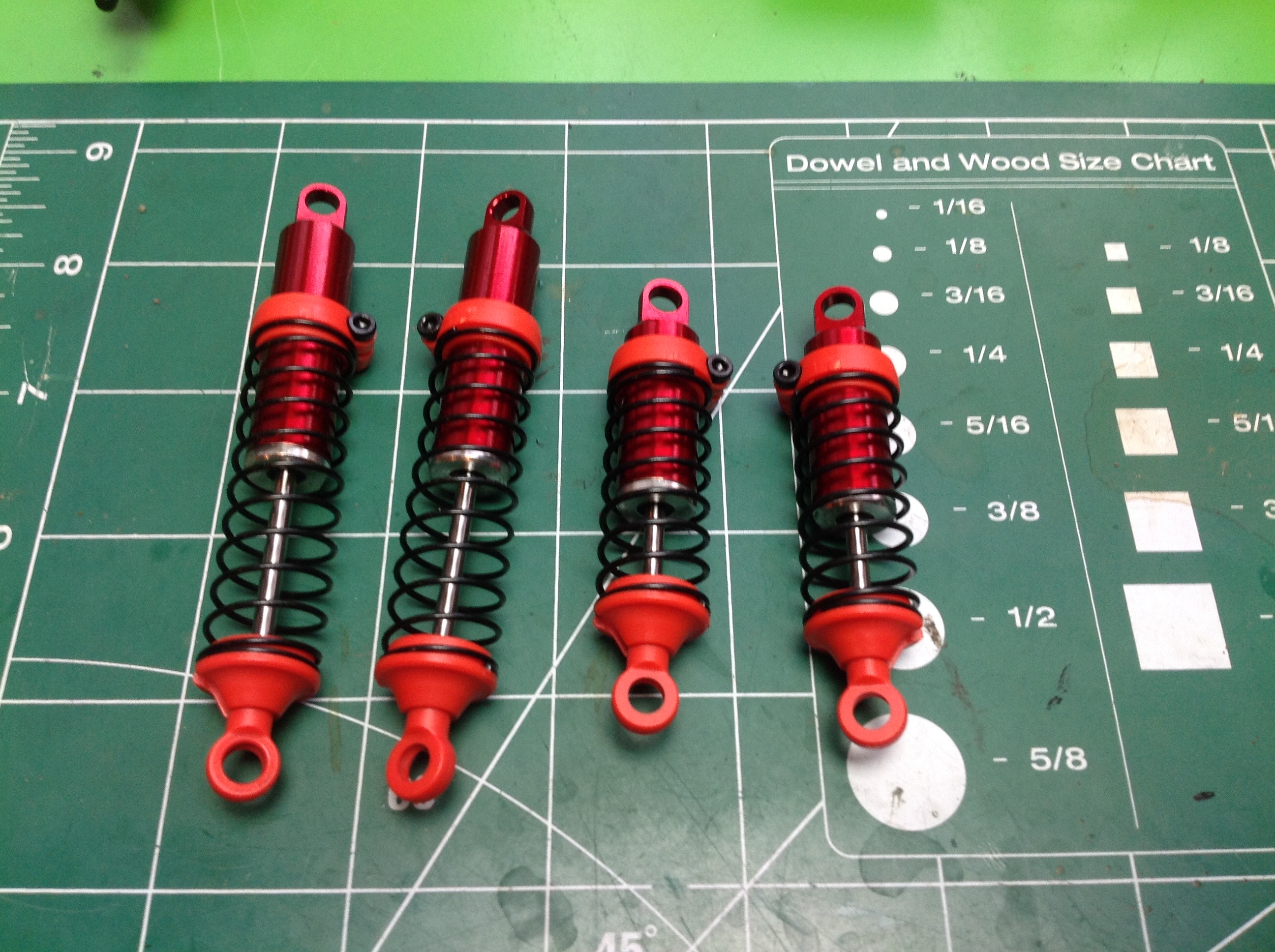
gland. The shock bodies are aluminum but are not externally
threaded for ride height adjustment. Instead, the spring collars
are clamped and can be slid along the outer diameter of the cylinders.
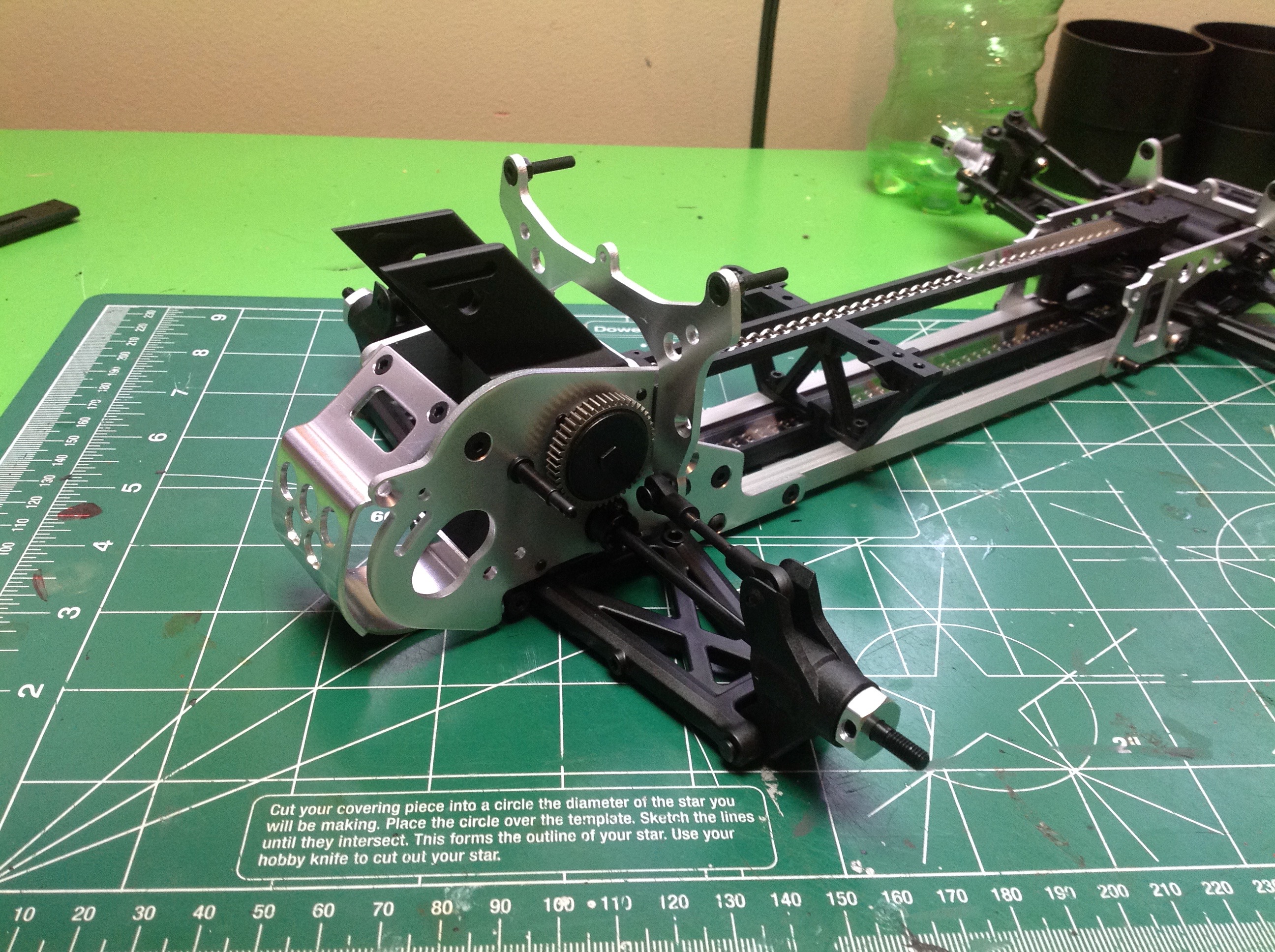
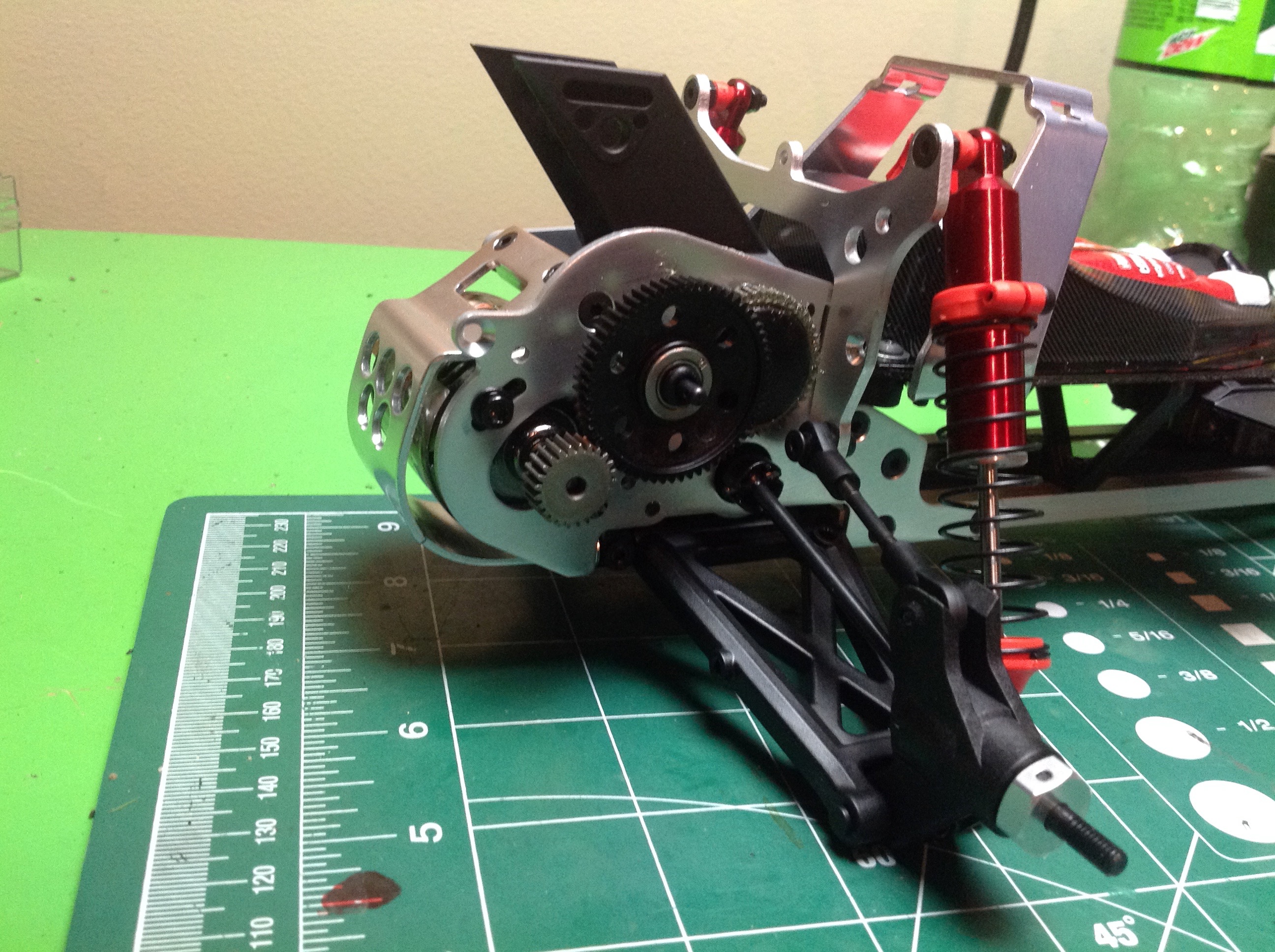
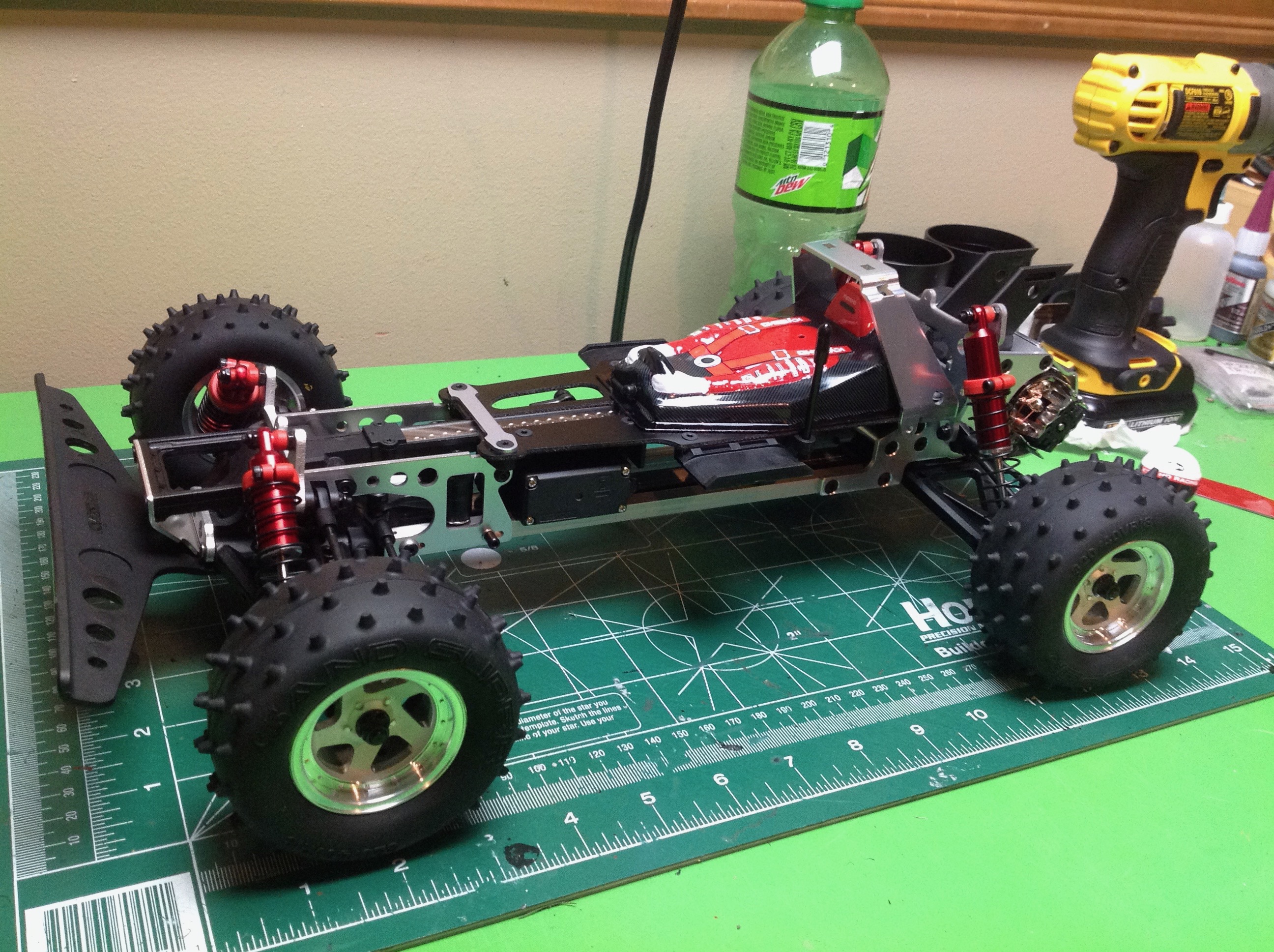
Once the shocks are installed the chassis looks nearly complete, but
there are still some external gears to install. The spur gear
rides on a fixed axle and connects the motor to the slipper with 2 stage
reduction (another stage being inside the bulkhead.) The motor
sits inside a protected shell behind the rear axle. I chose a
20-turn brushed motor from Orion which is the maximum speed recommended
for this model.
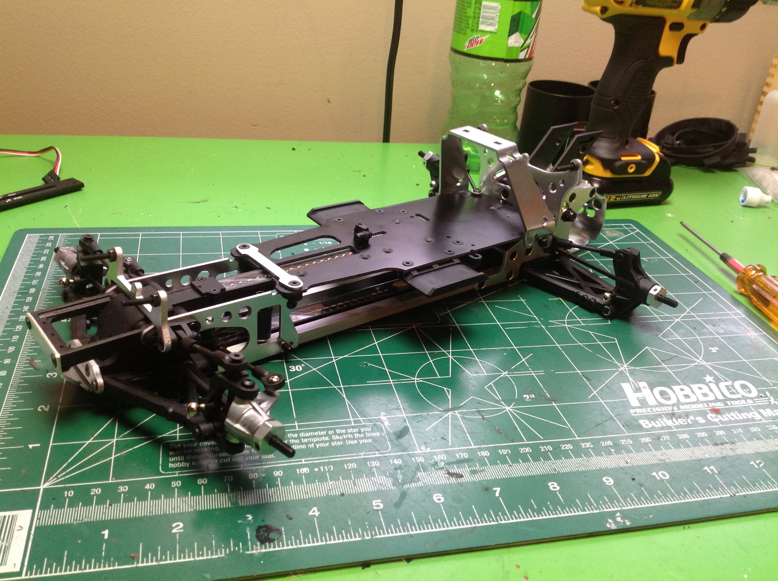
The steering servo can be seen peering out from under the upper plate
and is connected to a double bellcrank system. The driver shell
conceals the receiver. The ESC is less well contained and must
hang below the upper plate on the opposite side with minimal
space. I actually had to switch to a different speed controller to
fit the space. The wheels are handed; the left and right side are
different. This is that the spoke pattern appears to swirl
forward. The this point the structure is complete.
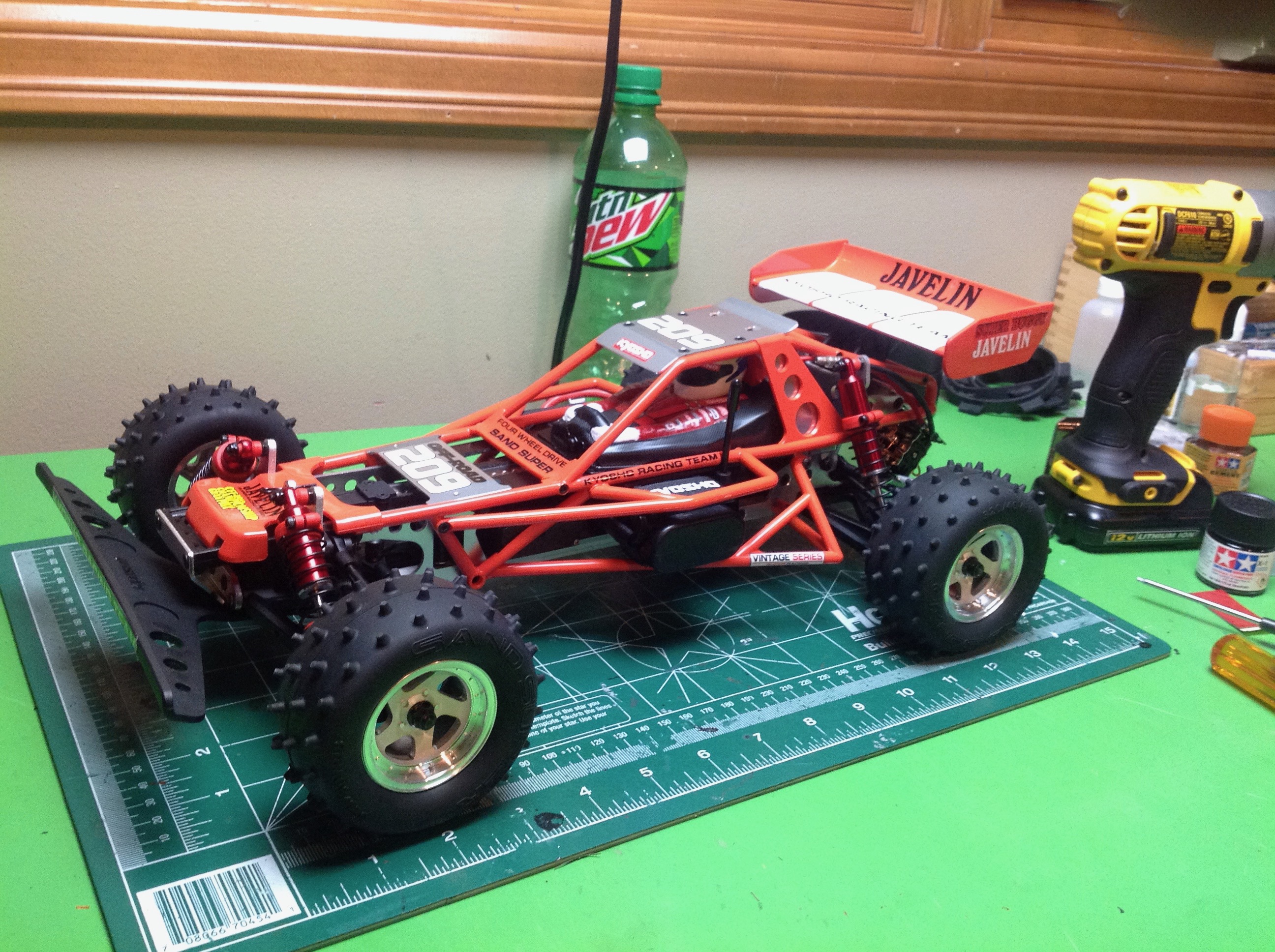
The cage is not really structural but mostly cosmetic, although I'm sure
it adds some stiffness. It bolts on in several places and does
not need to be removed to change the battery or do most
maintenance. The cage is assembled from multiple plastic pieces
and installed in three chunks: top, right, and left. The
sides are screwed into place but the top is affixed with body clips.
©2018 Eric Albrecht