Tamiya Hing Hauler Project
Page 6: Building the body
At this point all the mechanical and electrical construction is done
and it is time to do the detail work and painting of the body.
This is a whole different kind of work, and I like that this model
combines both in the same project.
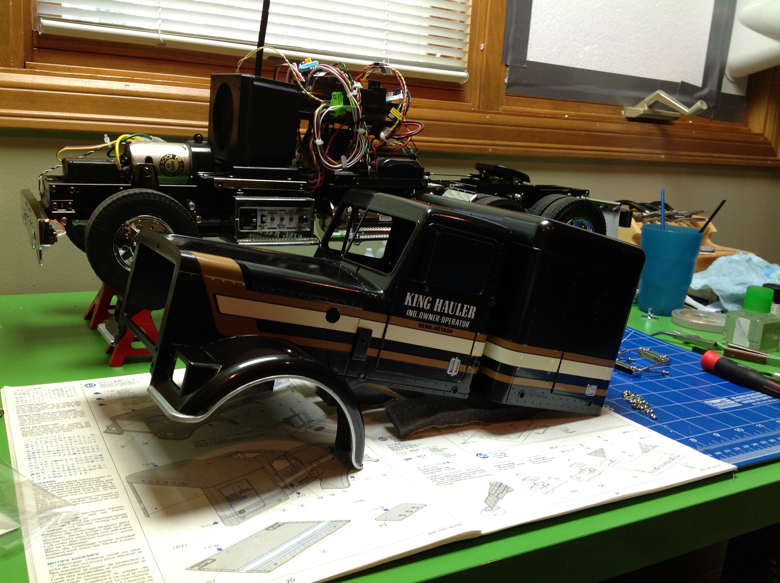
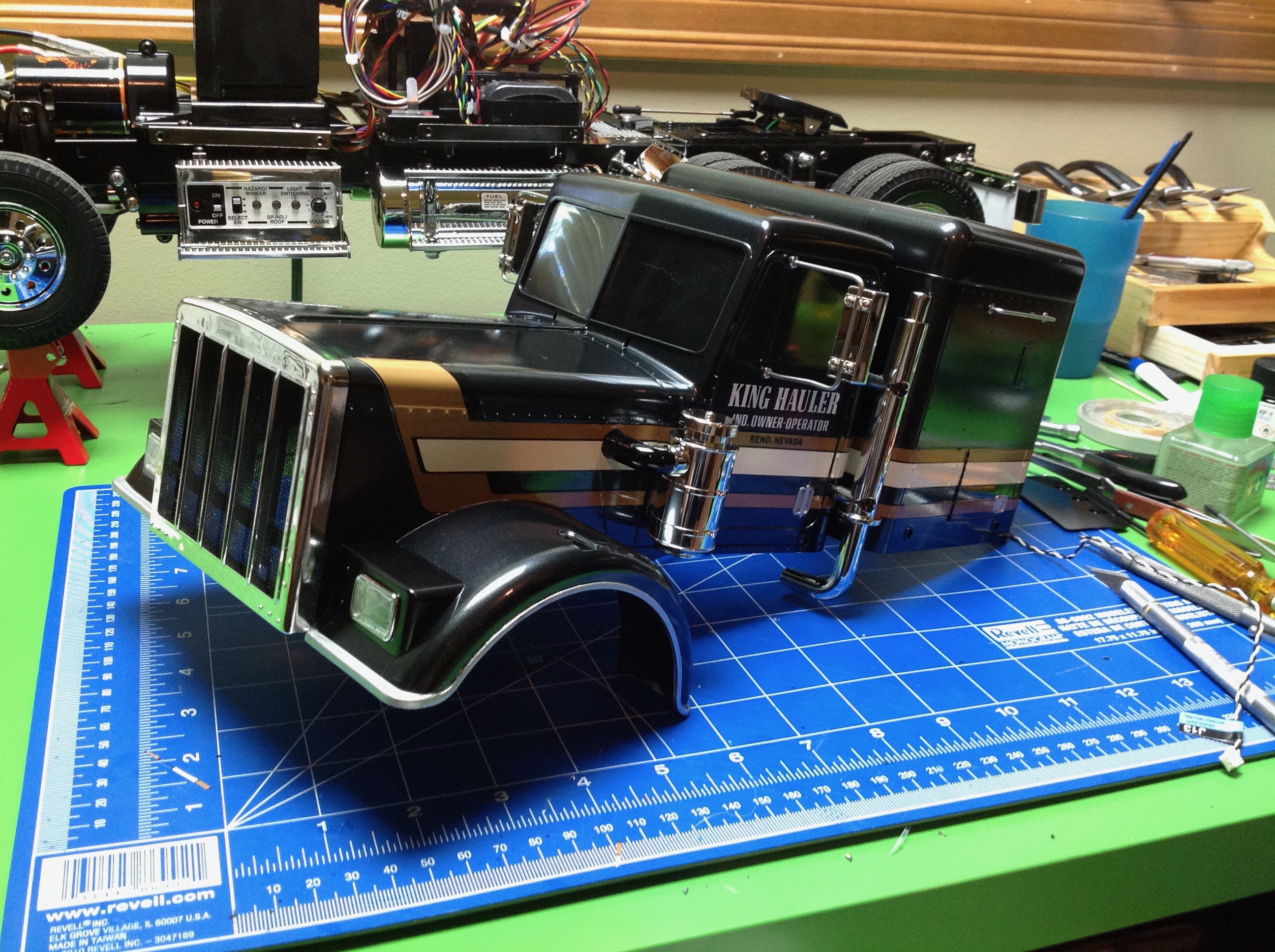
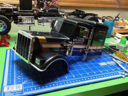
Step 42 takes longer than any other step in the instructions because
it involves painting and decorating the entire body. The body
comes as one part and the "black edition" that I'm using is pre-painted
in metallic black. The quality of the paint is really good: no
orange peel or dog hairs like when I do it myself. I had to
manually paint the silver around the wheel arches with a brush as well
as the door and storage handles. I wasn't sure whether the decals
were water slide or sticker, but it turns out they are stickers.
With big stickers, it is tricky to get them straight without any
wrinkles or bubbles. I spent a lot of time getting these just
right. The stickers are not pre-cut so you need to trim them with
an X-Acto knife or scissors. The closer you can get to the edges without leaving any
transparent film, the better it looks. As long as you don't go
over. I thought it looked a little strange to have the striped stickers
going over the door hinges, so I carefully trimmed them away in this
area.
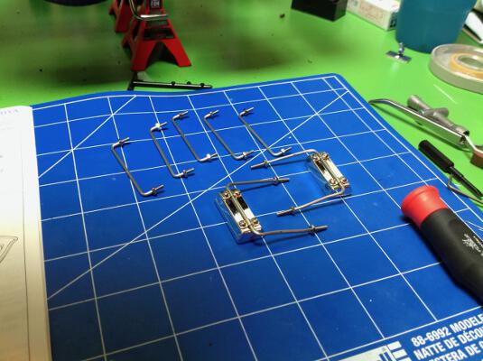
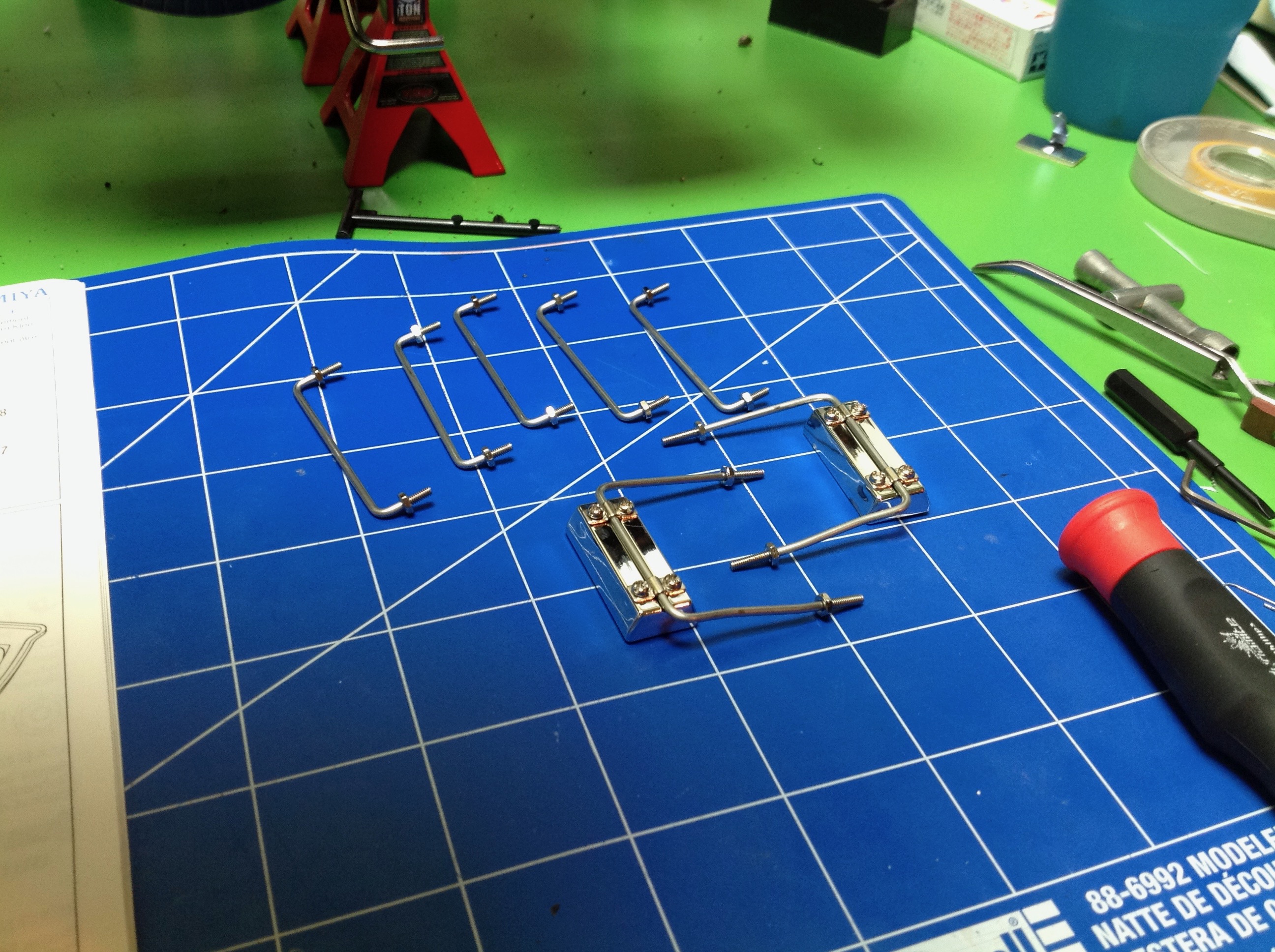
Step 43 is the side mirrors. The supports are threaded metal wire
but the mirror bucket is plastic. There are also 5 metal rails
here.

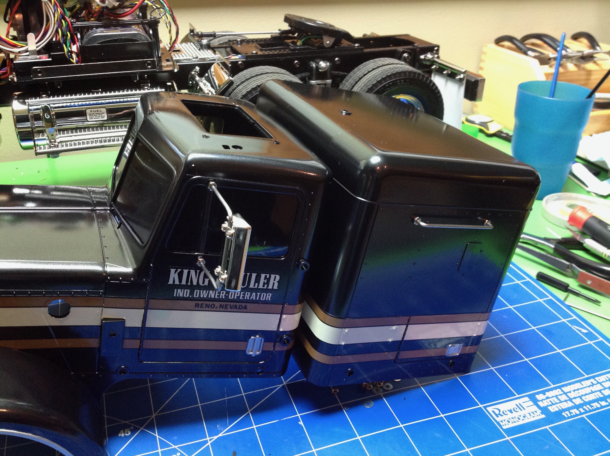
Step 44 installs the mirrors and handles to the body and also inserts
the darkened windows. In this picture they look pure black, but in
good lighting it is easy to see that they are translucent.
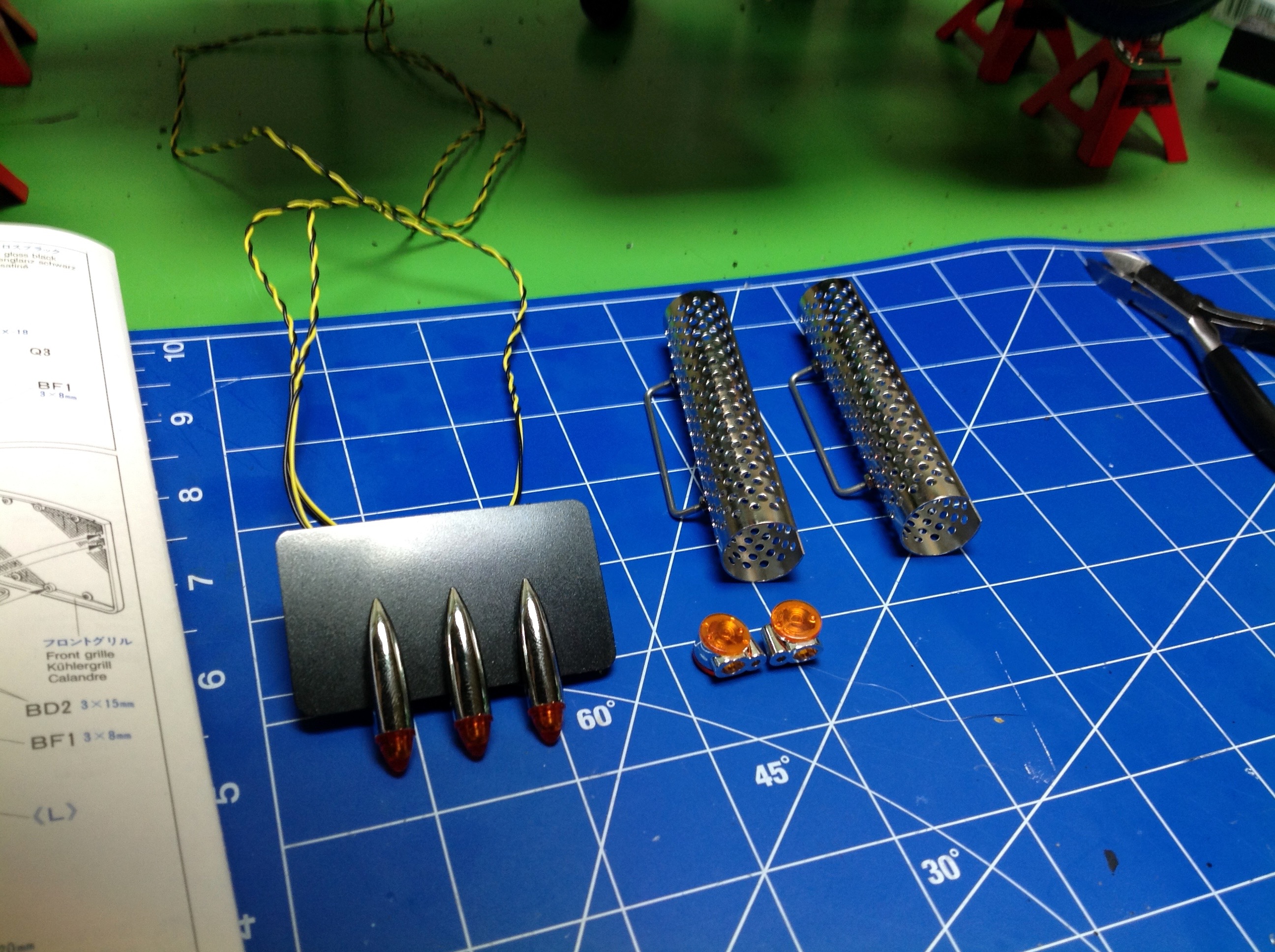
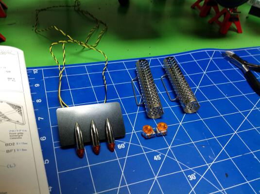
Step 45 builds the grille. Although it doesn't show up very well
in this photo, there is a photo etched black metal part representing the
radiator behind the chrome face. You can also see the chrome
light buckets which will make up the headlights. Each has a 5mm
white LED installed.

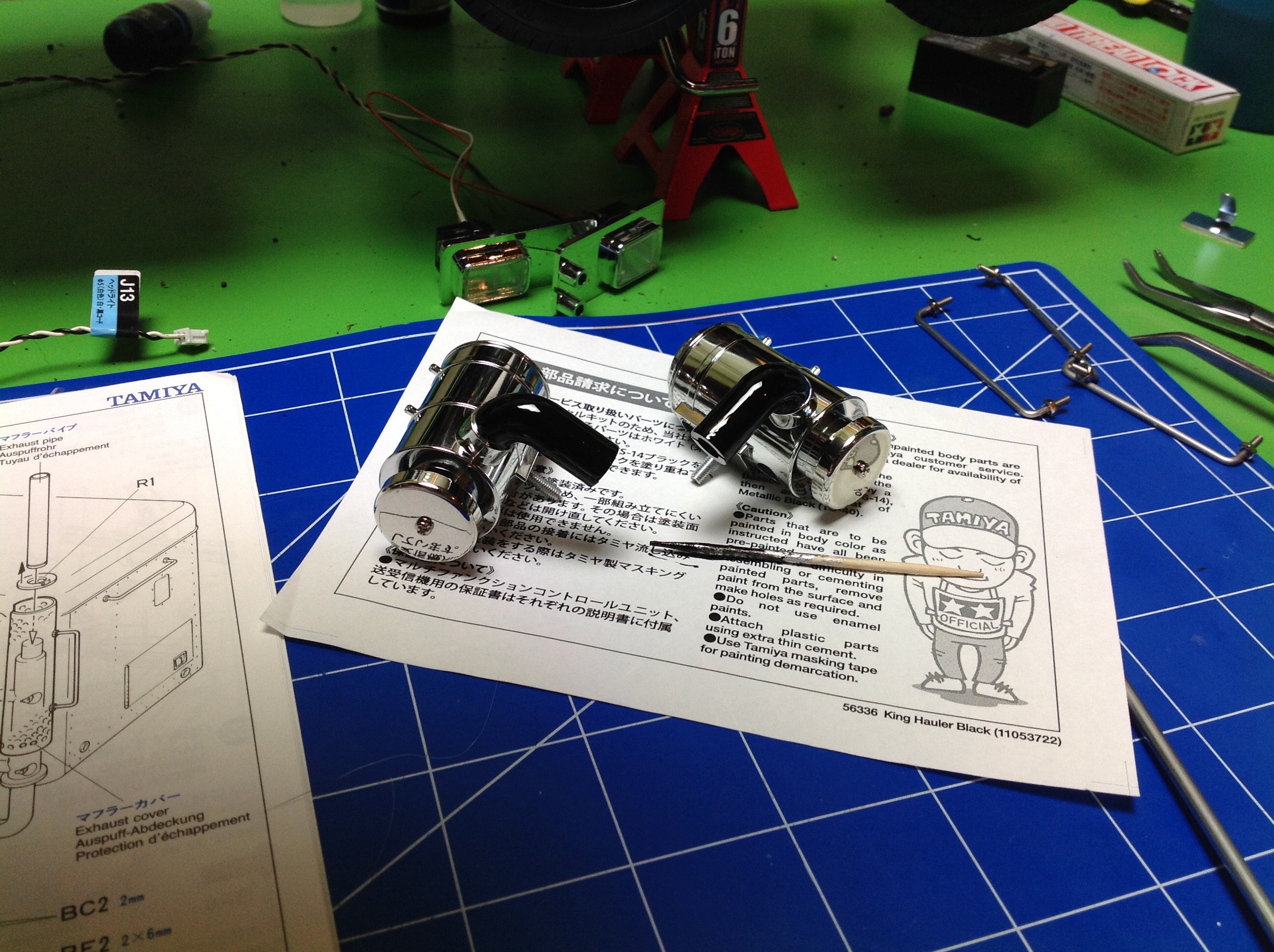
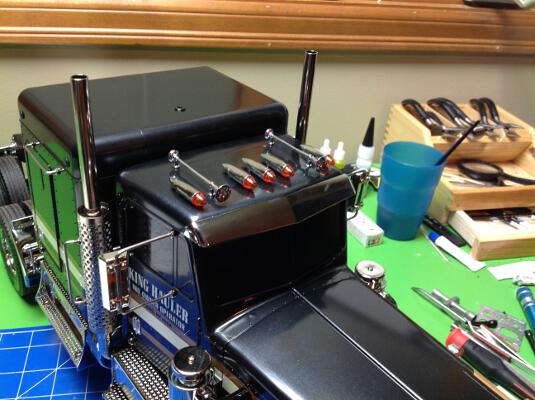
Step 46 involves the side air filters. The parts are chrome plastic, but I've painted the hoses black.
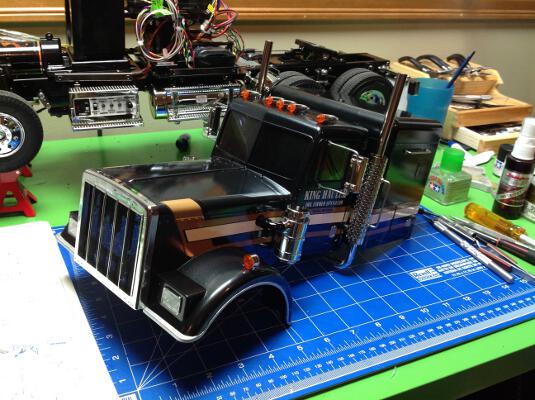
Now the filters, grille, headlights, and exhaust stacks are installed
onto the body in Step 47. From the side, the body looks pretty well
complete but we still have to work on the top.
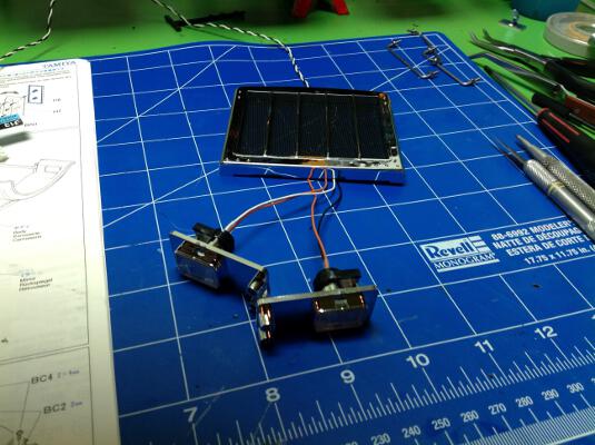
The roof has 5ea 3mm amber LEDs. The 2 on the outside light up any
time lights are on, but the 3 in the middle are special. Depending
on which lighting mode you have enabled, these 3 lights can visually
indicate which gear the transmission is in. You can also see the
blinkers which will mount to the fenders and the metal baffles for the
exhaust stacks. All these bits are made in Step 48.
Step 49 installs everything from the previous step. We'll be
skipping Steps 50-52 because they involve the dash, the seats and the
antenna which we aren't using. The dash and seats were replaced by
the speaker of the MFC, and the old style metal antenna is no longer
needed with modern 2.4 GHz radios.
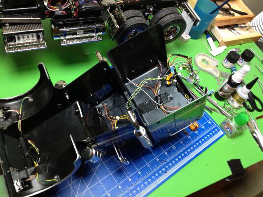

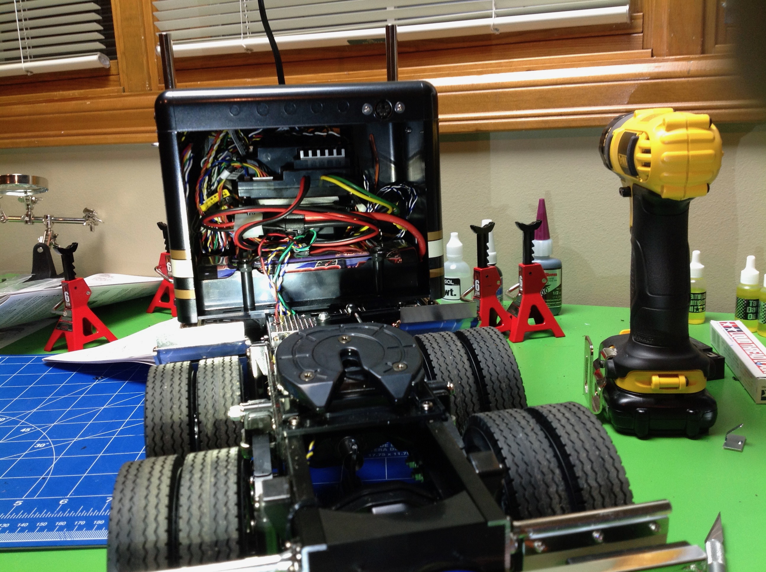
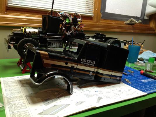
I took a couple of photos to show my attempts to organize the mess of
wiring. Of the 21 lights included with the MFC system, the King
Hauler doesn't use 6 of them. Among these are 4 AUX lights and 2
reverse lights. I couldn't very well just not use lights that I
had lying around, so I added some custom spots for them. The AUX
lights I installed two on either side of the sleeper as marker
lights. The reverse lights couldn't be accommodated on the rear
bumper so I put them on the back of the sleeper which actually works
really well for illuminating the trailer while hooking up in the dark.
I used black duct tape to secure the wires to the underside of the body
and group them. I separated them into 3 bundles which need to be
attached to the MFC when the body is installed. Reaching inside
the body from the back to attach all these wires in the right place
while installing the body is really hard. There is either no room
for my hand or no visibility of the ports. When I
realized how difficult it was going to be to attach the body, I resolved
not to have to do it again. With that in mind, I installed the
port for the trailer lights (upper right of second photo) and an
extension for the 4th servo which will later be used to control the
later legs.
Of course, I ended up removing the body again anyway because the AUX
lights turned out to be white which looked all wrong. I ordered
some amber lights and retrofitted them a couple of weeks later when they
arrived. Much better. At some point in the future I plan to
replace the pure white headlights with the more realistic halogen
colored versions which have recently become available.
Step 53 is the horns and the sun visor. Not sure why these weren't
attached before installing the body, but this is how the instructions
are sequenced.

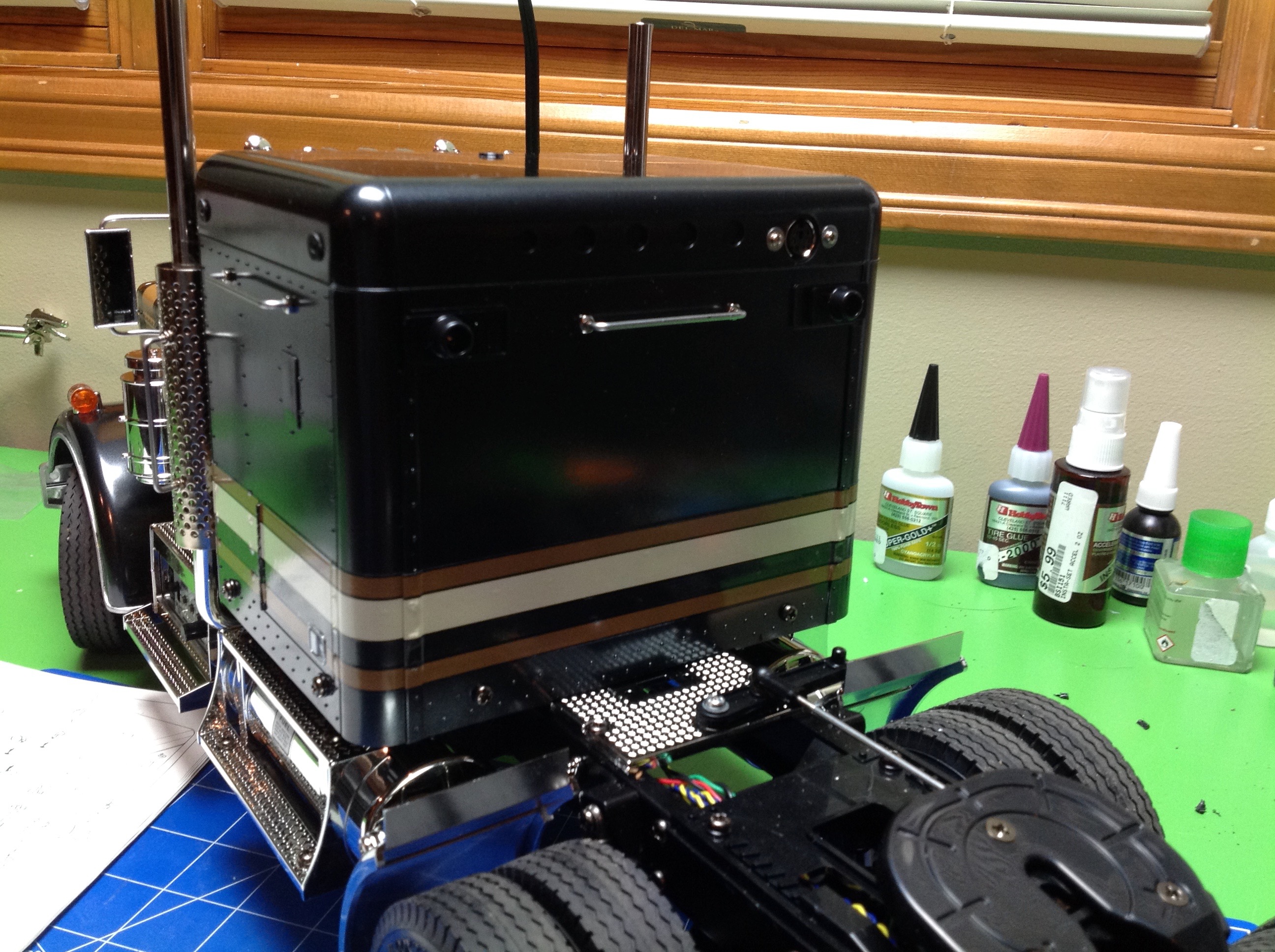
Step 54 is the final step of primary assembly and installs the rear
cover of the sleeper. This panel is removable to access the
battery compartment for charging. My 5000 mAh battery lasts a long time, but not forever.

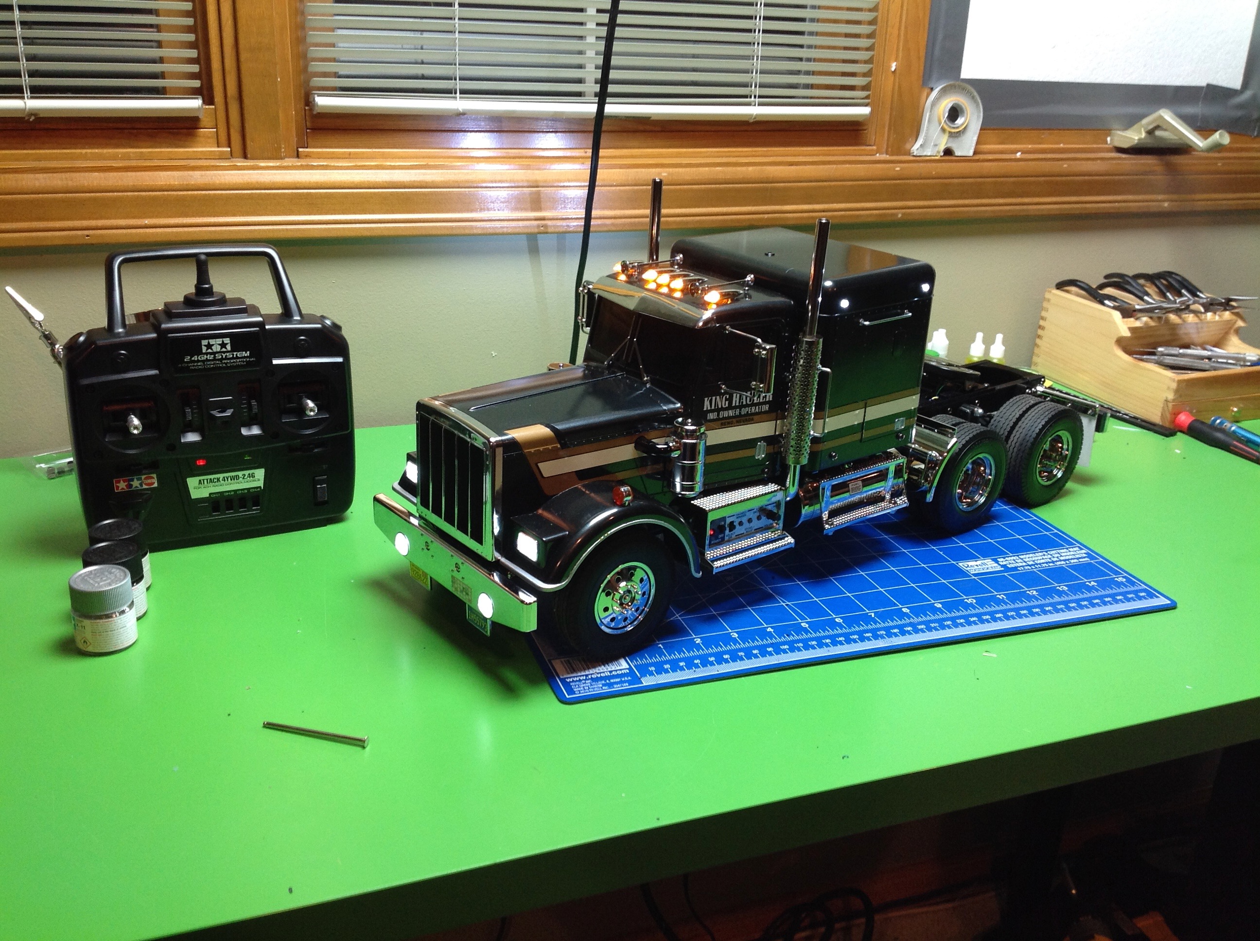
Done! Well, kind of. I still need to build the trailer and make
some mods to control the motorized legs, but at this point the truck is
ready to be driven. The MFC only works well with an older style 2
stick radio with analog trims. It can control more than 4
functions with only 4 channels by using small inputs from the trims for
some functions and large inputs from the sticks for others. The
sticks control throttle, steering, shifting, and coupling.
The trims control all kinds of light modes and sounds including a horn,
blinkers, flashers, reverse beep, and engine revving. You can rev
the engine in neutral without driving to hear the sound and watch the
vibrations. Reverse lights and sounds are automatic, but blinkers
are manual.
Both the throttle and the shifting are on the left stick. You need
to hold the stick left for 1st gear, middle for 2nd, and right for 3rd
all while controlling the throttle in the vertical direction. It
is hard to keep them independent and takes some practice. I would
have preferred a 3 position switch for the transmission. Another
thing I noticed right away to my surprise is that the truck was WAY too
fast for scale, even in 1st gear. I thought the single 540 sized
27-turn motor would be working pretty hard, but on pavement it moves
right along. I felt the speed was too far out of scale to leave
alone, so I picked up an Axial 55-turn motor which cuts the speed
roughly in half and looks MUCH better while still having plenty of
power. I didn't document the motor conversion, but you can see the
black motor at the edge of this picture.
There was virtually no glue involved in this entire project; everything
is mechanically fastened and therefore can be disassembled and
repaired. One spot there should have been glue was on the
headlight lenses. The first time I took this out driving I got
back to the garage only to find that the fog light lenses were
gone! They had rattled out. I had to order a replacement
transparent parts tree from Tamiya and replace them. This time I
used some thin cement. Don't use CA because it will fog the lenses as
it cures.
It looks strange for the desk to be clean and free of loose parts!
©2017 Eric Albrecht