Tamiya Leopard 2A6 Project
Page 3: Building the Suspension
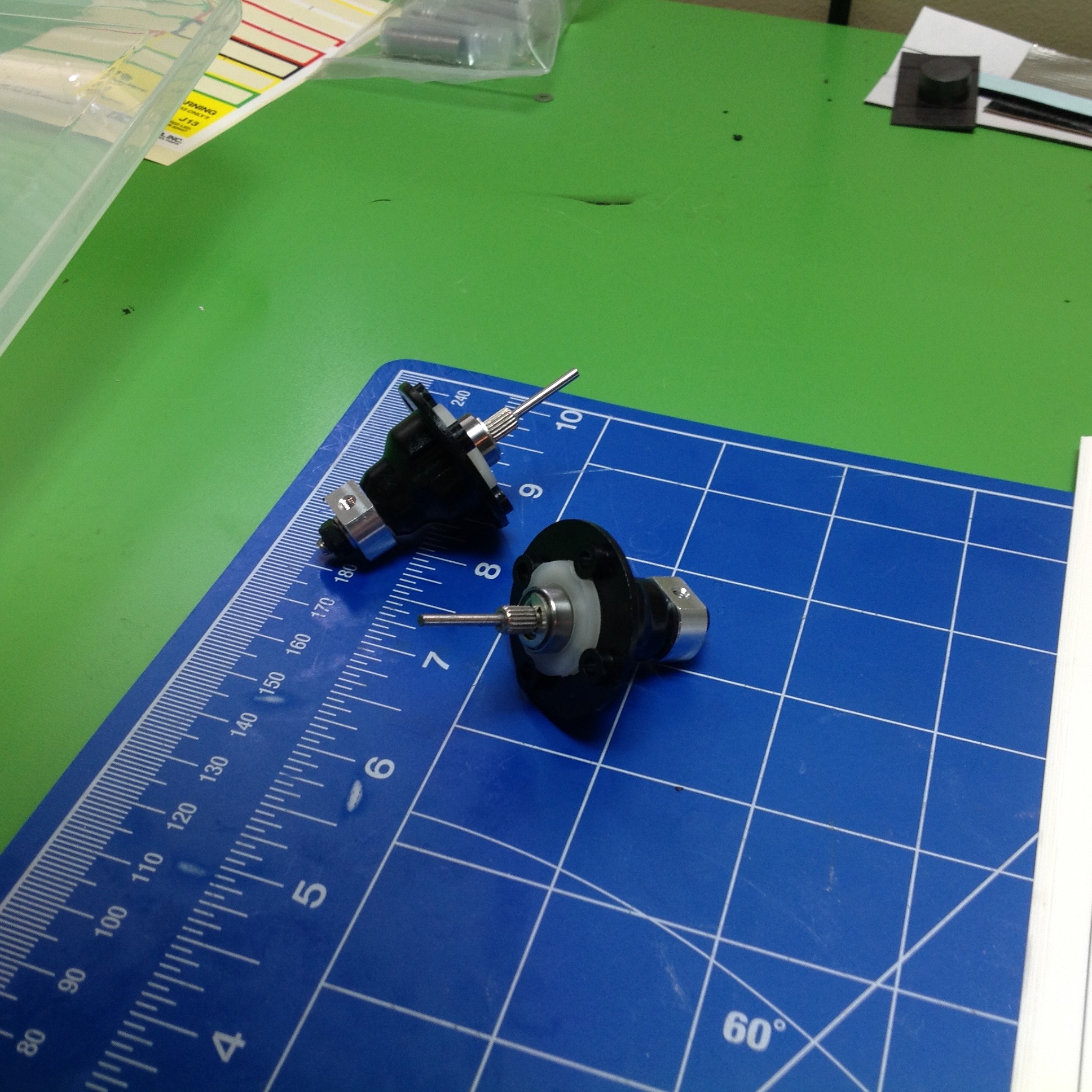
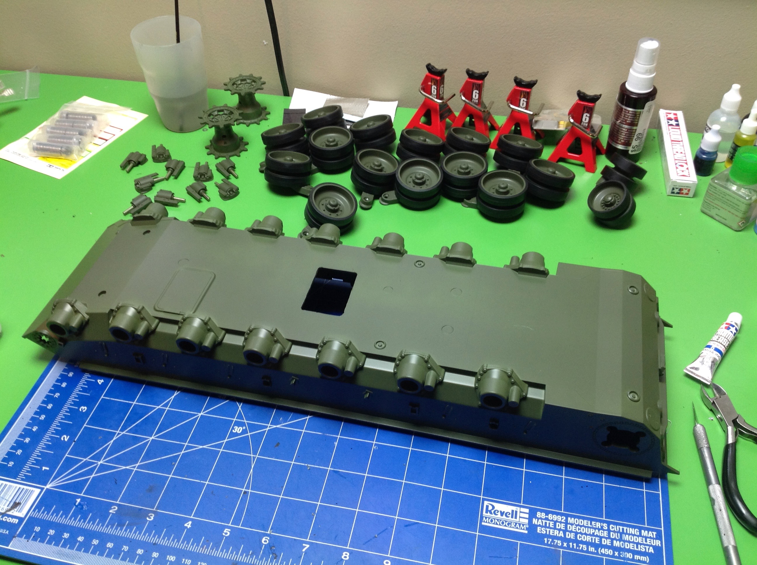
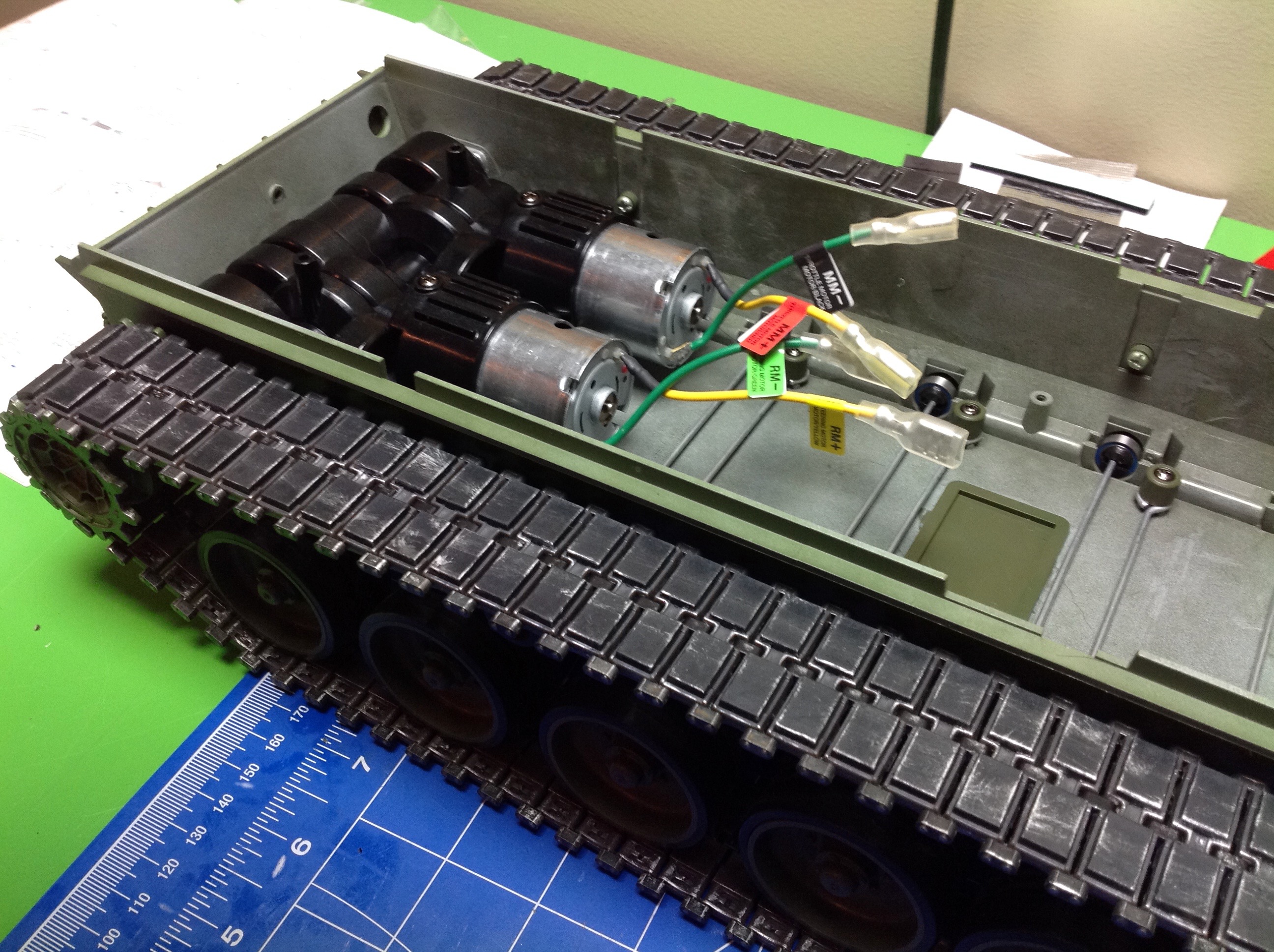
Step 11 begins construction of the driving mechanism of the hull.
We start with the drive shafts. These come directly out of the
gearbox and feed the sprockets. The thin shafts you see don't
carry torque, they just center the shaft in the differential.
Torque is carried between the spline and the hub.
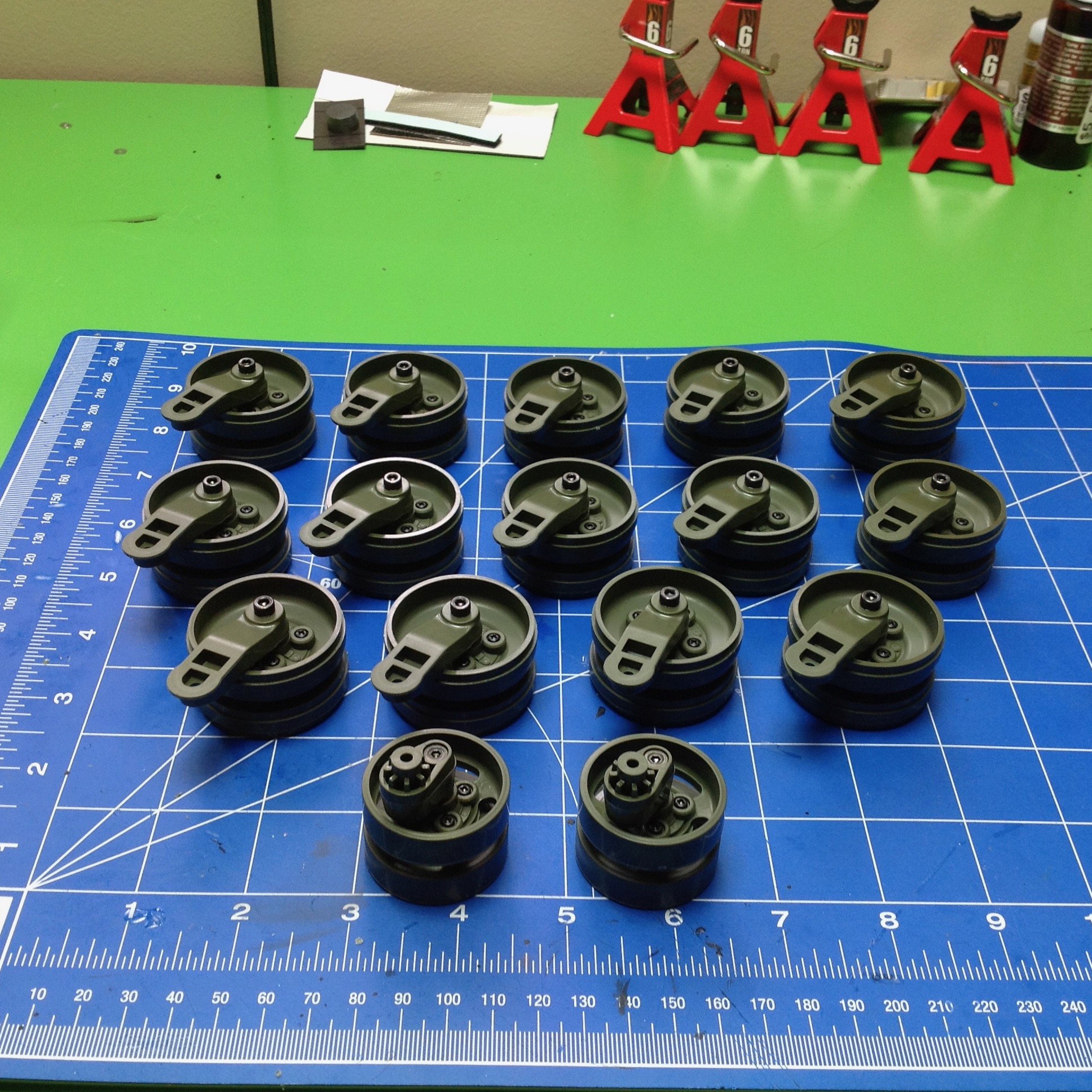
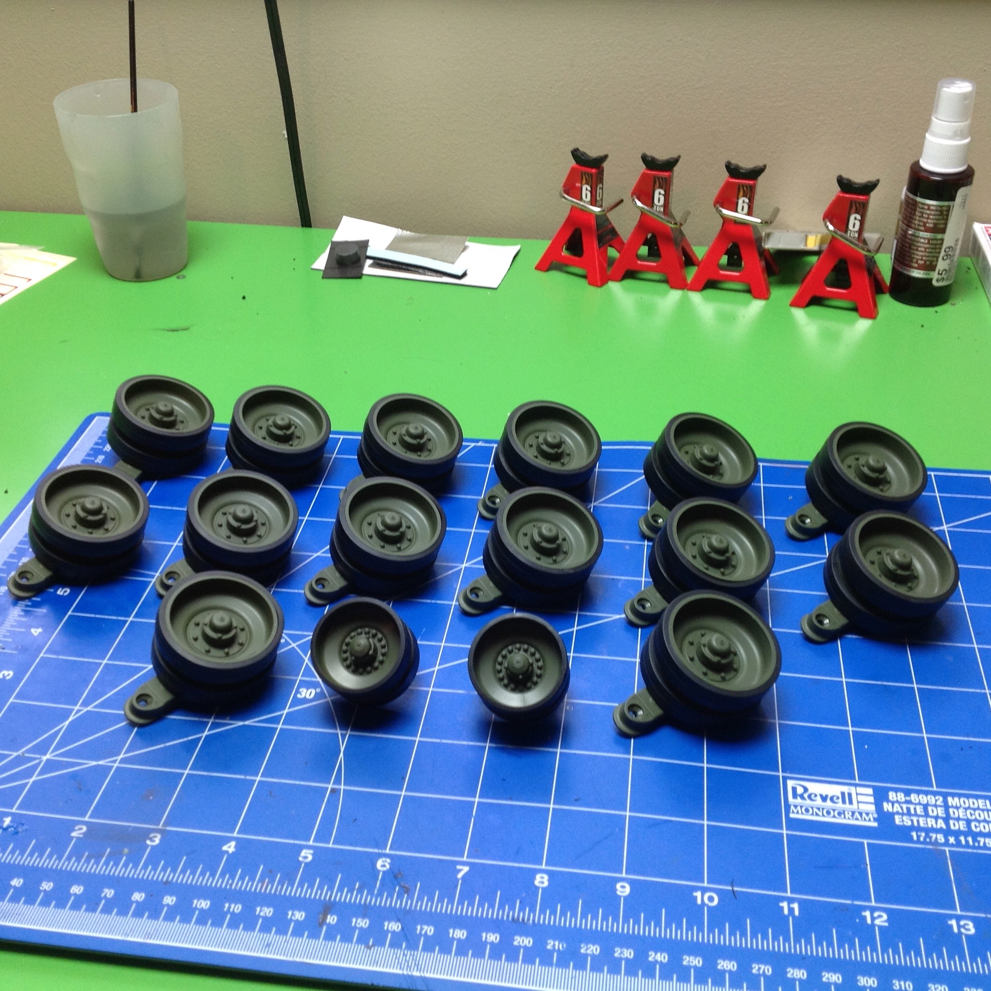
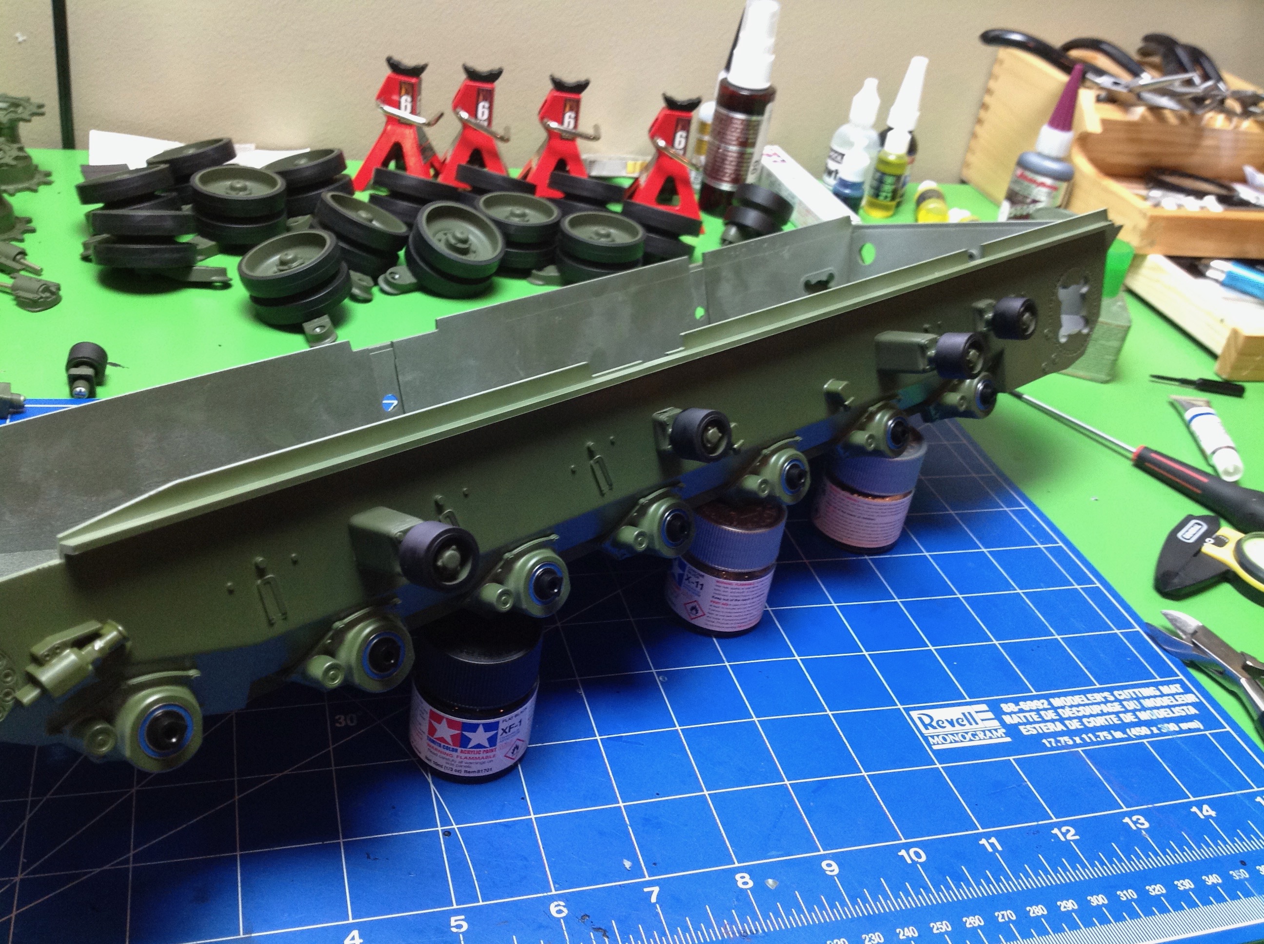
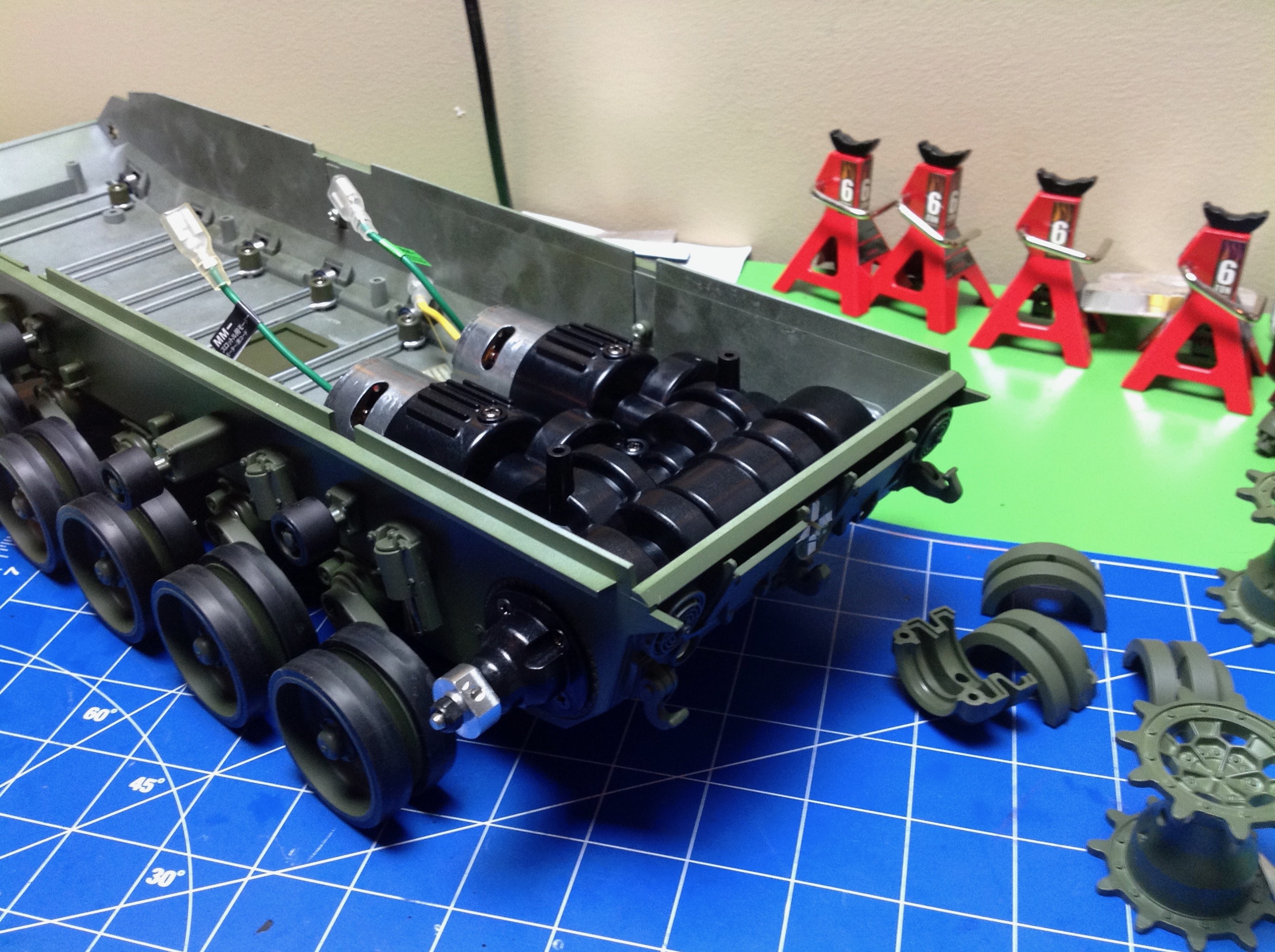
Next come the 14 road wheels in Step 12. You see 16 in the picture
but the bottom two are different. These are the tensioning
sprockets which go at the front of the track. I first sprayed all
the parts in NATO Green, then assembled them. After the paint was
dry, I attached the rubber tires over the road wheels as you can see in
the second image.
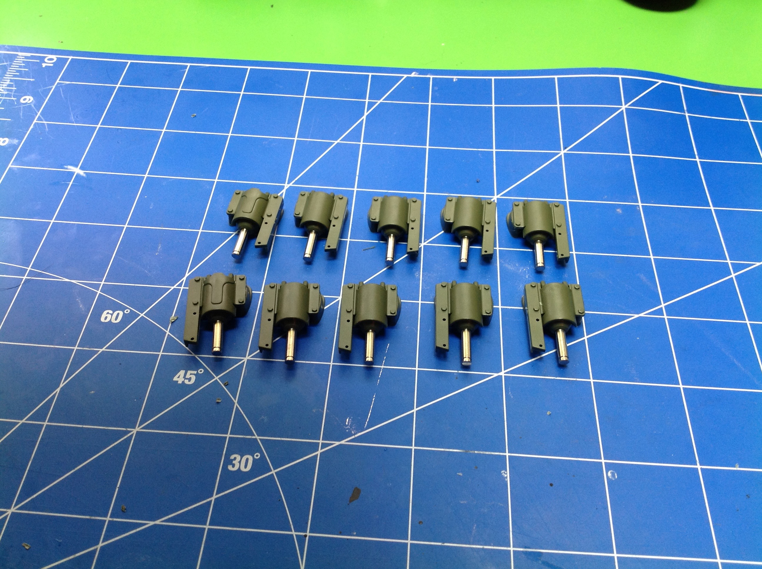
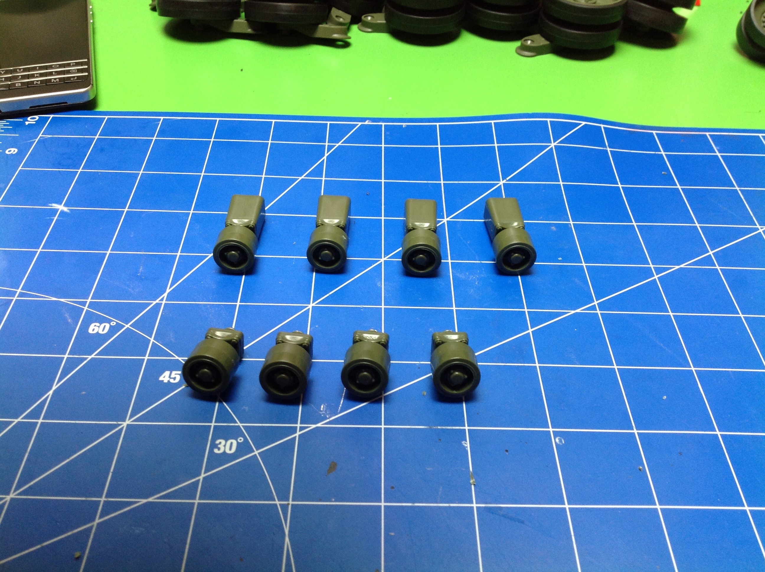
Next up come the 10 shock absorbers in Step 13. There are
actually 4 types. Left and right are mirrors of each other and the
two at the left end have a slightly different pattern on the can.
Although there are springs inside, these serve only as scale details
and don't add anything to the suspension of the model. They soften
the impact of the swing arms against the stops in the event the torsion
rods bottom out.
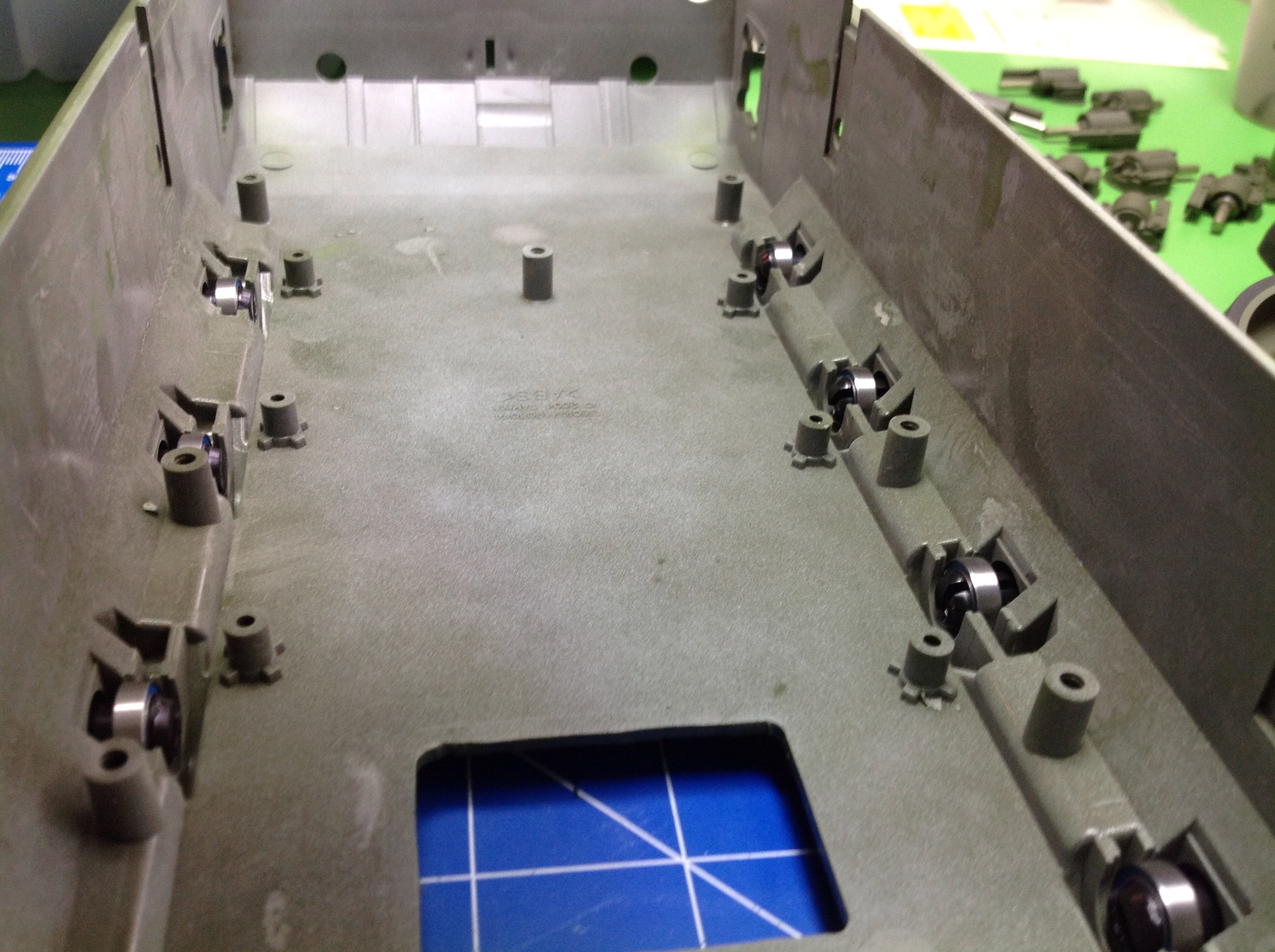
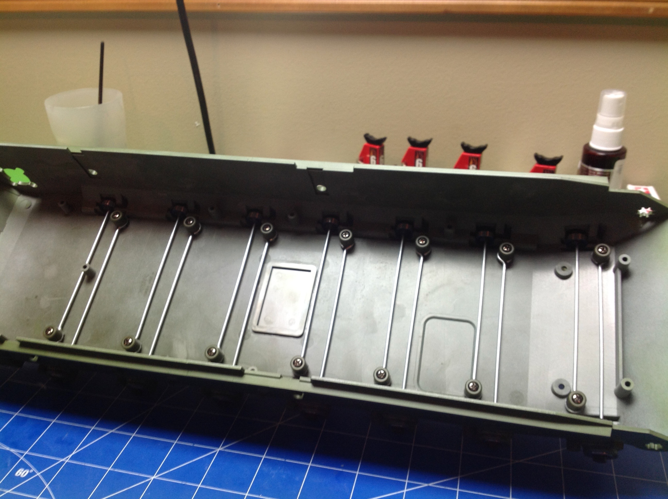
Step 14 installs the bearings and axles for the torsion bar
suspension. The kit comes with metal bushings here. I had
already ordered ball bearings to replace all the bushings in the set,
but it turns out I could have saved myself some money here. These
are not high speed rotating shafts, these are just suspension
joints. One could argue the bushings are actually better because
they will resist ingress of dirt and water better. However, I
already had the bearings so I went ahead and installed them (24
bearings).
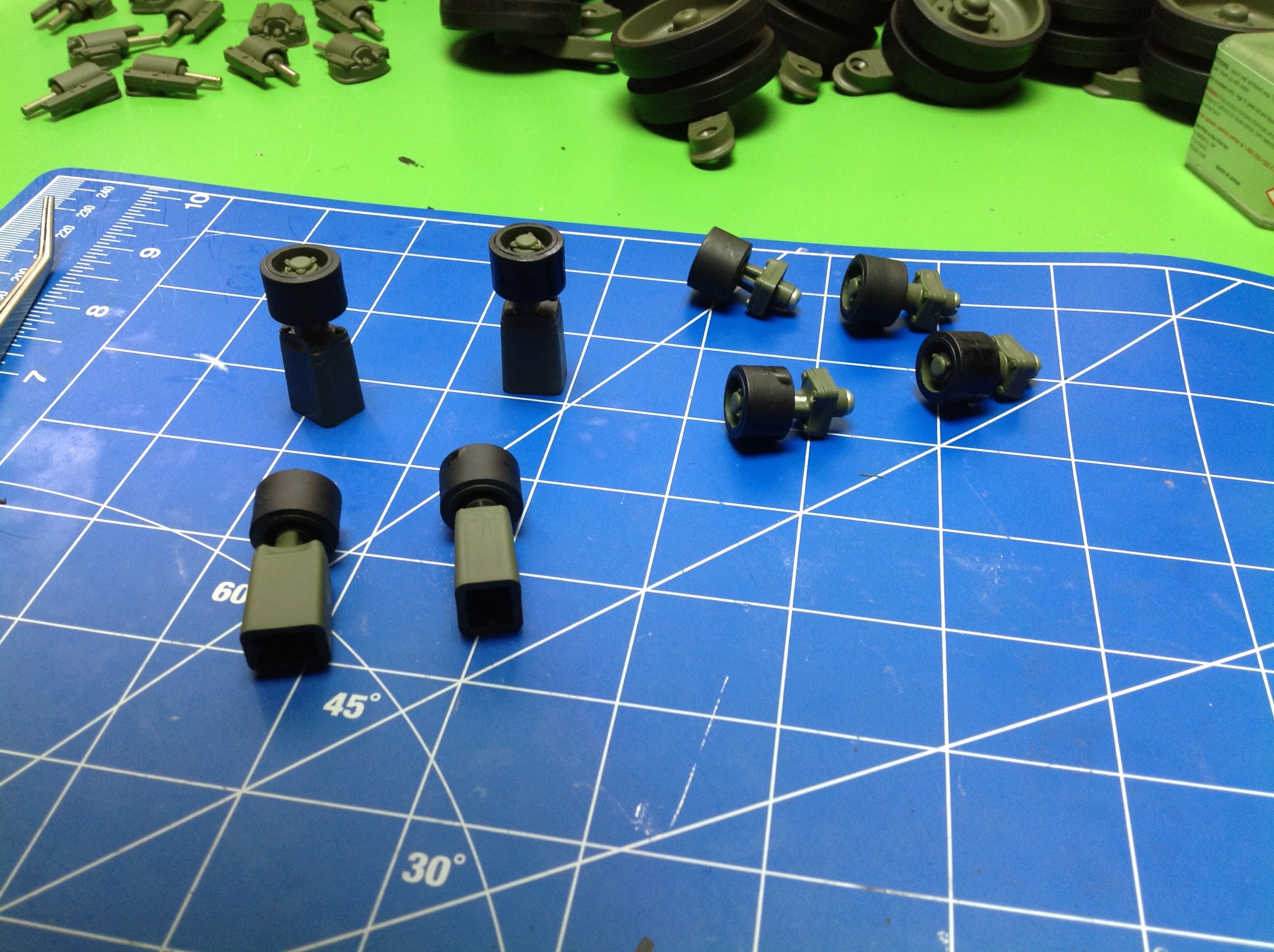
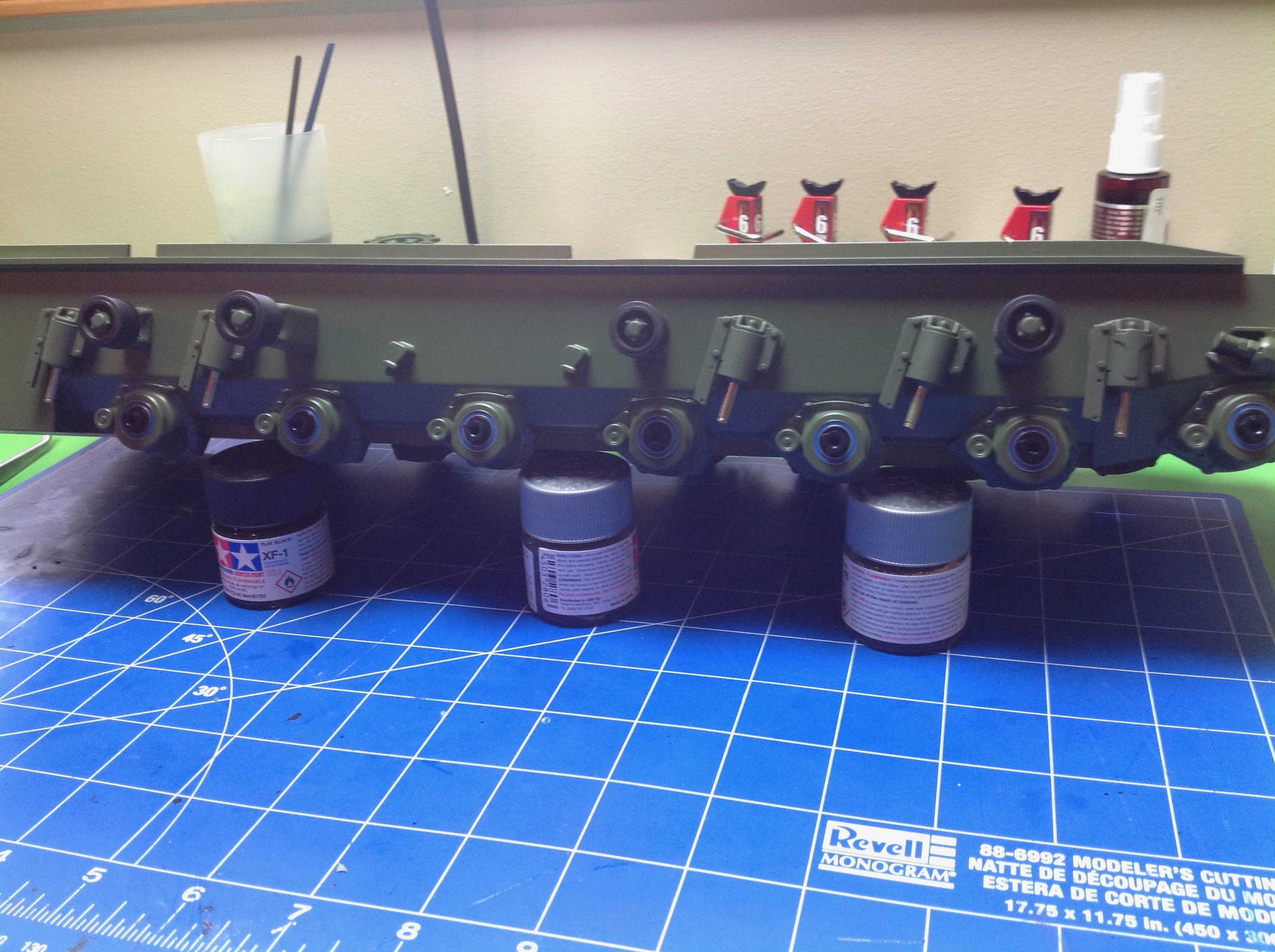
Step 15 is the return rollers. These serve only to hold the track
up on its journey from the tensioning sprocket back to the drive
sprocket. I first painted and assembled them and then painted the
tires flat black. Unlike the road wheels, there are no rubber
tires provided here so paint will have to provide the illusion.
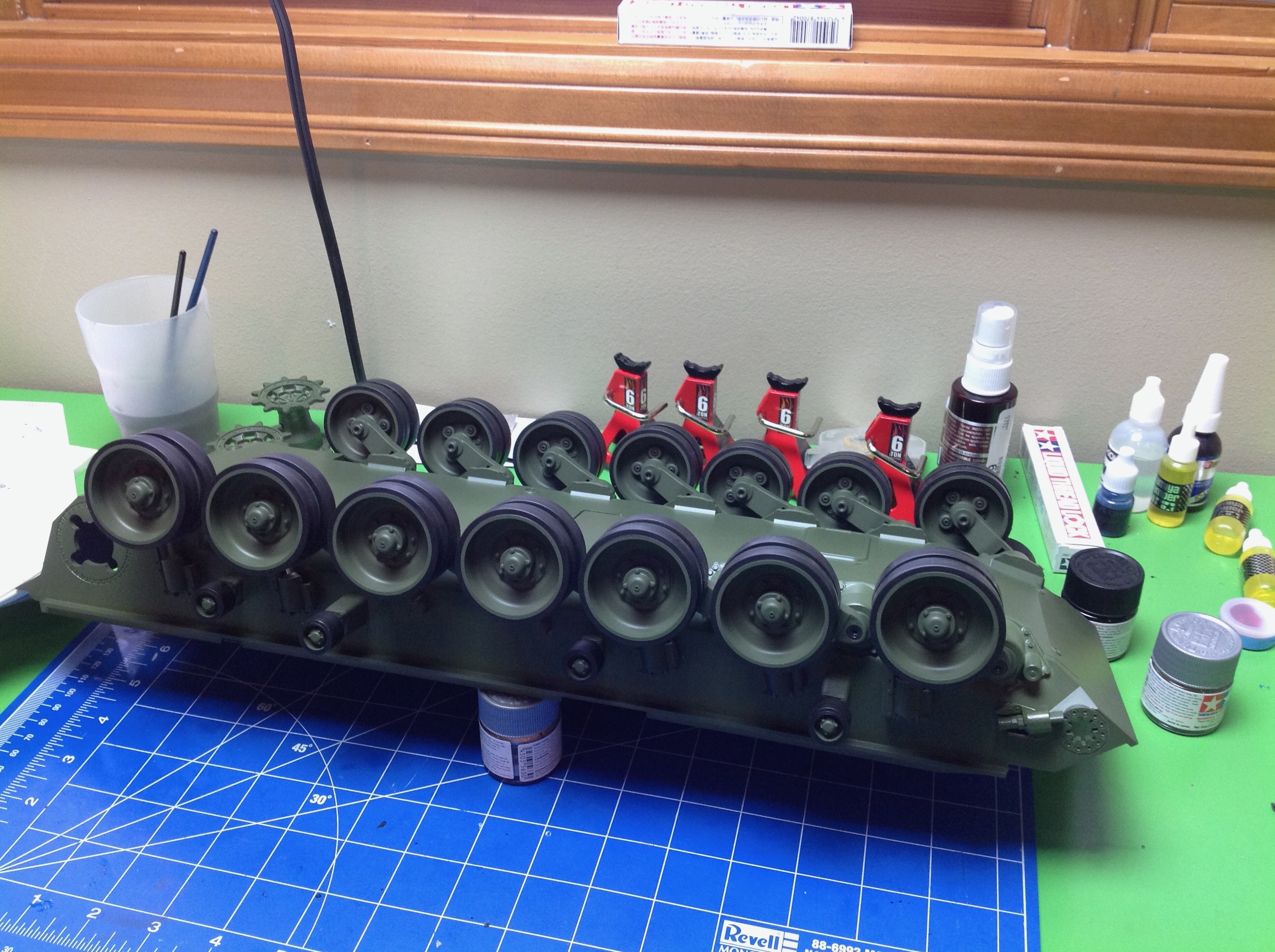
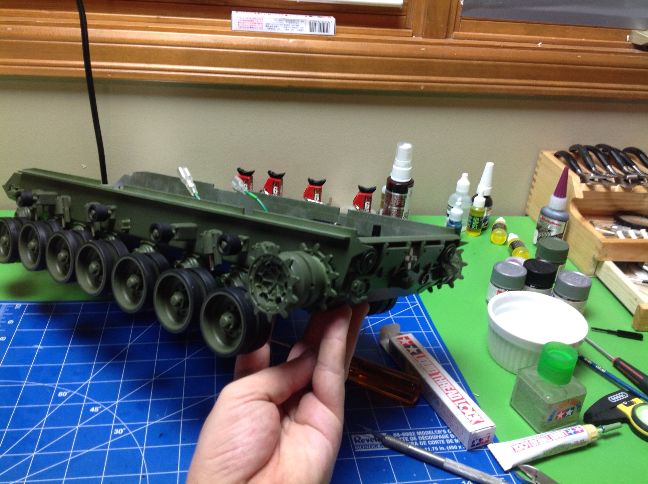
Now the torsion bars and return rollers are installed. The torsion
bars travel the width of the hull and are attached to the road wheel
axles at one end and anchored to the hull at the other. These
twist up to about 30 degrees under wheel loading and seem to be very
durable. The spring rate seems to be also about right for the
weight of the vehicle. As a consequence of the offset torsion
bars, the wheels on the right and left of the hull are not aligned but
are offset about 1 cm.
MUCH later I discovered that I had used the wrong screws in this step
when I did not have the correct number left for another step in the
turret. I had to tear the whole model apart down the this hull
base to
extract them.
The return rollers are glued to the hull and cantilever quite a long
distance. For this reason they are pretty fragile so you need to
be careful not to put too much weight on them.
Step 17 glues on the shock absorbers. This is a very simple
step. There is an index mark to show where each goes on the hull.
Step 28 attaches the road wheels. Every one of these 14 assemblies
is the same so you can't screw it up. You only need to make sure
that each swing arm is angled back. Now you can set the tank on
its wheels and try out the suspension. At this point the model is
still very light so the suspension doesn't feel right.
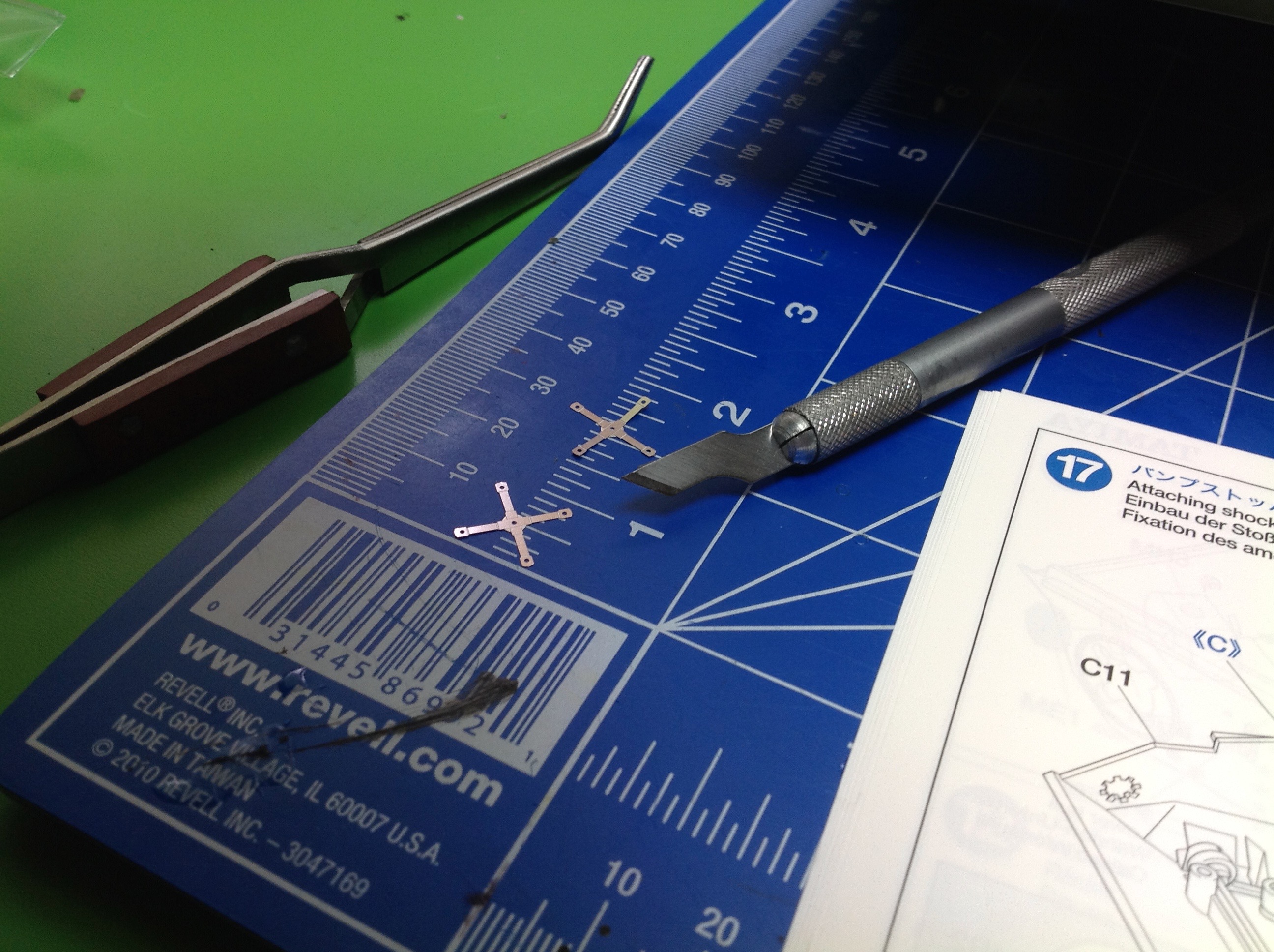
Step 19 tells you how to cut out photo etched parts. This is
fairly important because this is very thin sheet metal and some of the
parts are tiny and all are fragile. You don't want to twist them
to remove them from the tree or they will get warped. The photo
shows how small the smallest is.
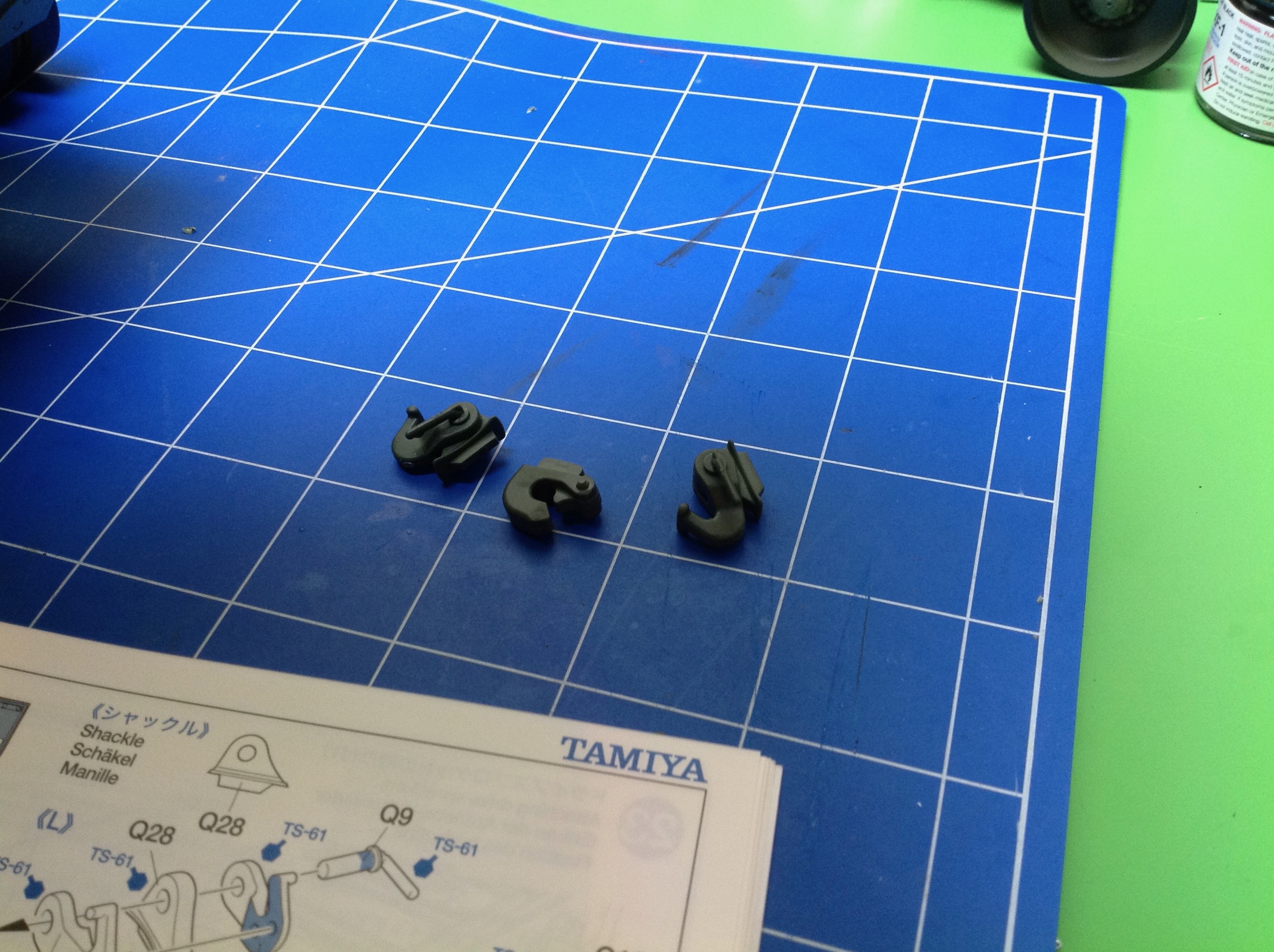
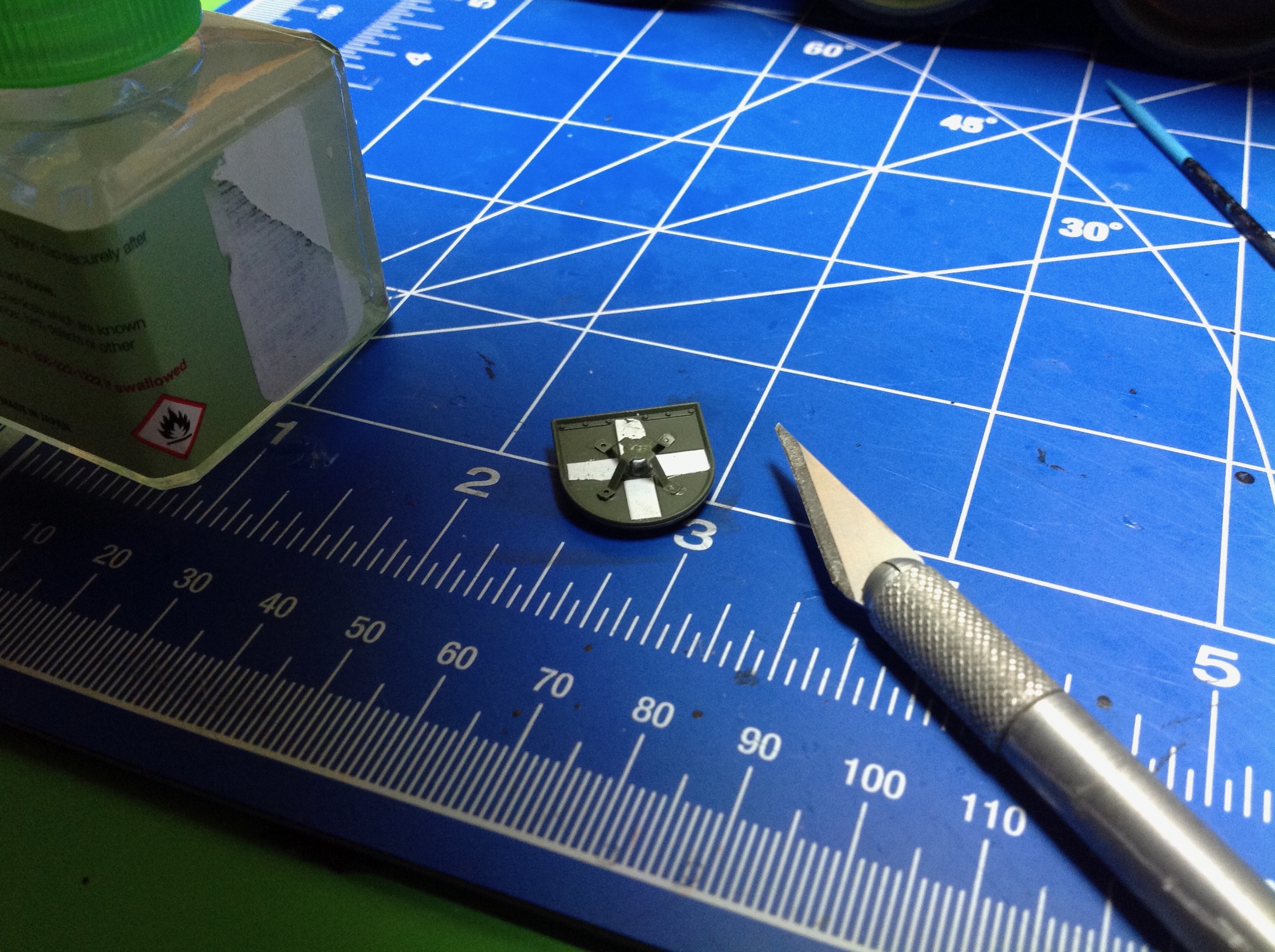
Step 20 builds some accessories for the rear of the hull including a
pintle hook, a couple of shackles, and a convoy marker. The convoy
marker is shown in the right hand image. The tiny metal photo
etched part needed to be bent into the small tower in the middle, and
beneath is a clear cone for light. The white stripes are decals:
the first in the model. The whole thing is only 1 cm wide. I
didn't expect to be dealing with such small parts in such a big model.
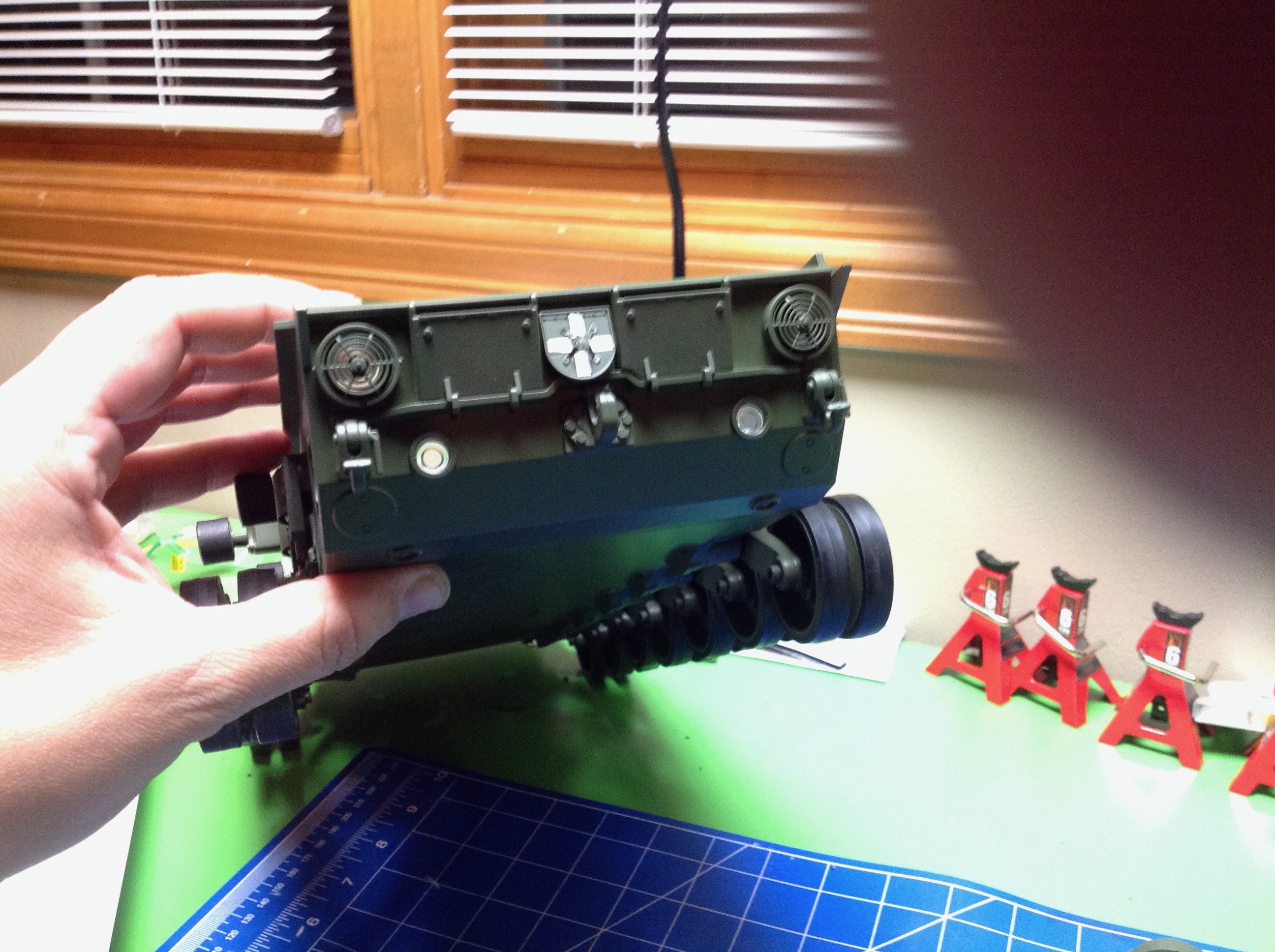
Step 21 installs a bunch of bits to the rear of the hull including the
assemblies from Step 20 and some exhaust ports, tail light lenses, and
panels. At this point I still need to paint those lenses
transparent red. I didn't have any such paint yet and the hobby
store was closed so I just kept building. Of course, the very next
step blocks access to these so disassembly was required the next day to
paint them. Once I am on a roll building, I can't stop.
Step 22 installs the transmission and output axles into the hull.
The assembly order means that if you ever want to remove the
transmission for maintenance (or access) later, you first need to remove
the tracks and the axles which insert from the outside.
The main drive sprockets are the first cast metal parts. These needed to be primed and painted prior to assembly.
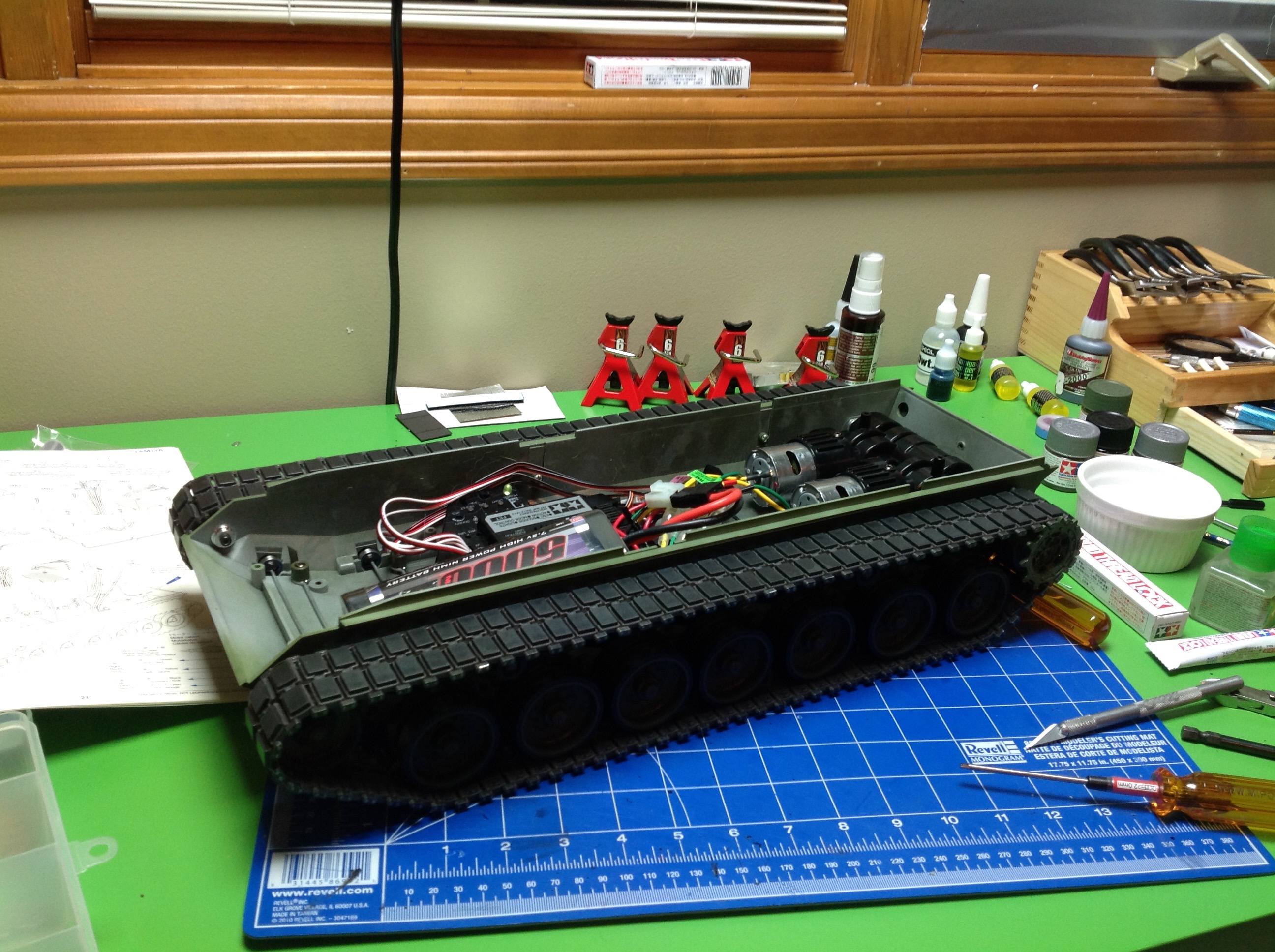
And now the tracks! The tracks come pre-assembled as a single
piece and are tensioned by rotating the forward sprocket. Of
course I threw in a battery and drove the hull around at this
point. I was surprised by how fast it is. In the right hand
image you can see the results of a dry brushing technique I used to
weather the tracks and make them looked like scratched metal.
Although it looks good, this was folly for two reasons. First, all
the paint wore off the first time I drove the tank. This kind of
detailing only works on static models. Second, the real Leopard
tank has rubber pads on the track just like the model, so these would
never look like worn metal anyway. Some rust on the areas
underneath would not be amiss though.
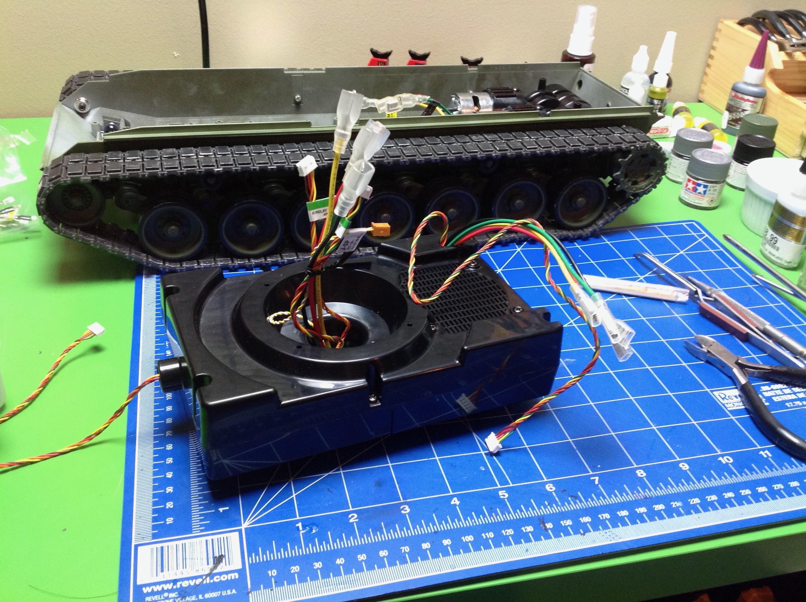
Step 25 is the speaker box. The speaker is screwed down into the
box and various wires for the hull are routed through it. The box
makes an effective acoustic chamber and really amplifies the apparent
volume of the speaker. The fact that wires will be passing from
the hull to the turret means that the turret will not be able to rotate
360 degrees without fouling the wires.
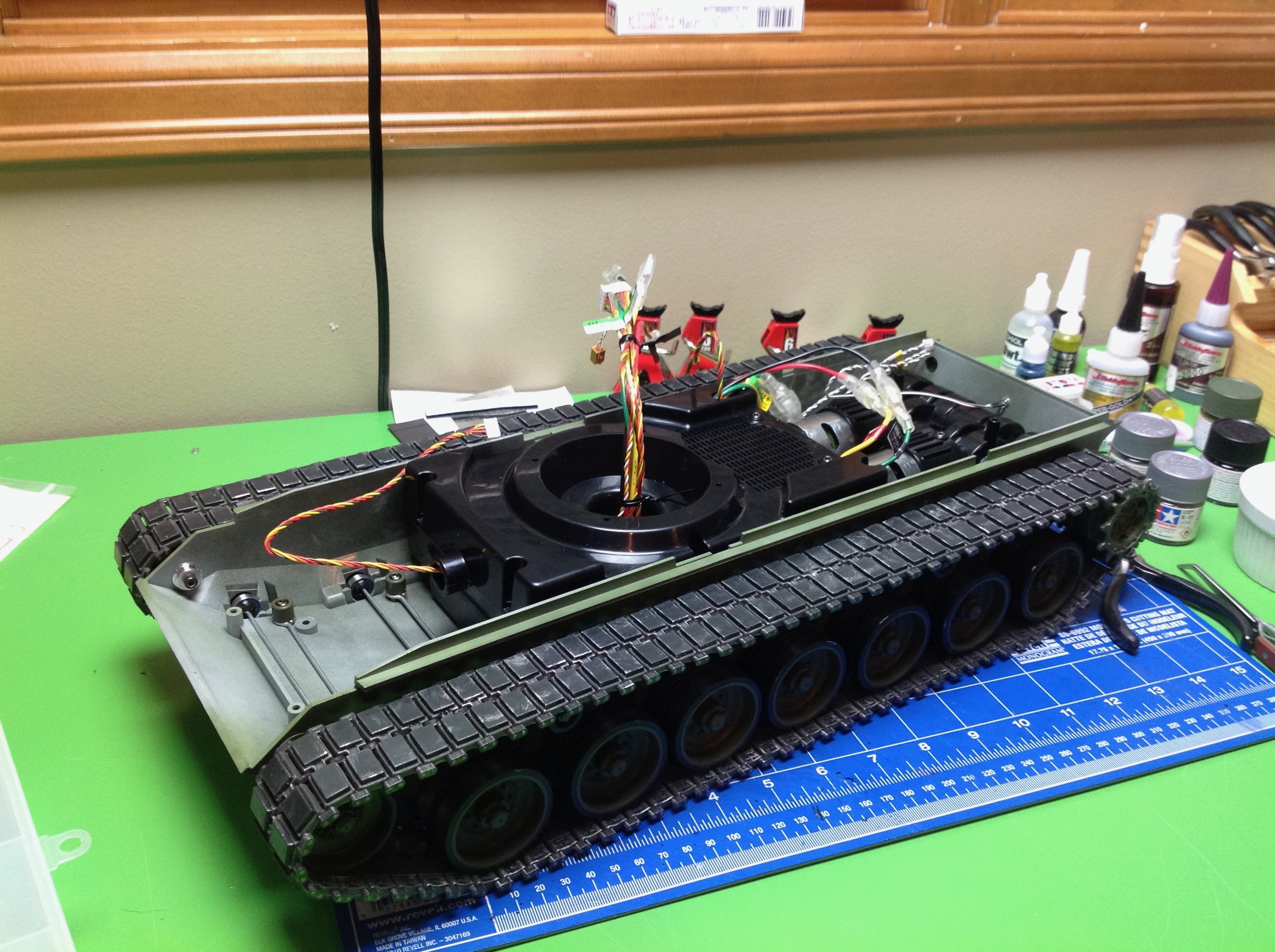
To complete the hull, the speaker box is installed in Step 26.
Oddly, it is not actually fastened down. It just sits on a couple
of studs.
©2017 Eric Albrecht